EP3466458B1 - Intra-aortale ballonvorrichtung und unterstützungsvorrichtungen zur verbesserung von fluss, gegenpulsation und hämodynamik - Google Patents
Intra-aortale ballonvorrichtung und unterstützungsvorrichtungen zur verbesserung von fluss, gegenpulsation und hämodynamik Download PDFInfo
- Publication number
- EP3466458B1 EP3466458B1 EP18204523.7A EP18204523A EP3466458B1 EP 3466458 B1 EP3466458 B1 EP 3466458B1 EP 18204523 A EP18204523 A EP 18204523A EP 3466458 B1 EP3466458 B1 EP 3466458B1
- Authority
- EP
- European Patent Office
- Prior art keywords
- balloon
- expandable frame
- flow
- check valve
- pumping
- Prior art date
- Legal status (The legal status is an assumption and is not a legal conclusion. Google has not performed a legal analysis and makes no representation as to the accuracy of the status listed.)
- Active
Links
- 230000001435 haemodynamic effect Effects 0.000 title 1
- 238000005086 pumping Methods 0.000 claims description 134
- 210000000709 aorta Anatomy 0.000 claims description 55
- 230000002093 peripheral effect Effects 0.000 claims description 18
- 230000006870 function Effects 0.000 claims description 8
- 238000000465 moulding Methods 0.000 claims description 5
- 238000004026 adhesive bonding Methods 0.000 claims 2
- 238000009958 sewing Methods 0.000 claims 2
- 239000008280 blood Substances 0.000 description 44
- 210000004369 blood Anatomy 0.000 description 44
- 230000000694 effects Effects 0.000 description 36
- 210000002254 renal artery Anatomy 0.000 description 36
- 238000000034 method Methods 0.000 description 30
- 230000004087 circulation Effects 0.000 description 29
- 238000011144 upstream manufacturing Methods 0.000 description 24
- 238000003780 insertion Methods 0.000 description 21
- 230000037431 insertion Effects 0.000 description 21
- 210000002376 aorta thoracic Anatomy 0.000 description 20
- 210000004556 brain Anatomy 0.000 description 18
- 210000005240 left ventricle Anatomy 0.000 description 17
- 210000001367 artery Anatomy 0.000 description 16
- 230000003416 augmentation Effects 0.000 description 16
- 230000000903 blocking effect Effects 0.000 description 16
- 230000017531 blood circulation Effects 0.000 description 16
- 229920003023 plastic Polymers 0.000 description 15
- 239000004033 plastic Substances 0.000 description 15
- 239000000463 material Substances 0.000 description 13
- 210000001765 aortic valve Anatomy 0.000 description 12
- 230000010412 perfusion Effects 0.000 description 12
- -1 polyethylene Polymers 0.000 description 12
- 208000014674 injury Diseases 0.000 description 11
- 230000008733 trauma Effects 0.000 description 11
- 230000000747 cardiac effect Effects 0.000 description 10
- 210000001105 femoral artery Anatomy 0.000 description 9
- 238000005304 joining Methods 0.000 description 8
- 230000033001 locomotion Effects 0.000 description 8
- 239000012528 membrane Substances 0.000 description 8
- 239000002184 metal Substances 0.000 description 8
- 210000000056 organ Anatomy 0.000 description 8
- 239000004698 Polyethylene Substances 0.000 description 7
- 229920000573 polyethylene Polymers 0.000 description 7
- 239000002699 waste material Substances 0.000 description 7
- 230000008901 benefit Effects 0.000 description 6
- 238000006073 displacement reaction Methods 0.000 description 6
- 210000003141 lower extremity Anatomy 0.000 description 6
- 229920002635 polyurethane Polymers 0.000 description 6
- 239000004814 polyurethane Substances 0.000 description 6
- 238000011176 pooling Methods 0.000 description 6
- 208000001647 Renal Insufficiency Diseases 0.000 description 5
- 238000013459 approach Methods 0.000 description 5
- 230000036772 blood pressure Effects 0.000 description 5
- 230000007423 decrease Effects 0.000 description 5
- 201000006370 kidney failure Diseases 0.000 description 5
- HLXZNVUGXRDIFK-UHFFFAOYSA-N nickel titanium Chemical compound [Ti].[Ti].[Ti].[Ti].[Ti].[Ti].[Ti].[Ti].[Ti].[Ti].[Ti].[Ni].[Ni].[Ni].[Ni].[Ni].[Ni].[Ni].[Ni].[Ni].[Ni].[Ni].[Ni].[Ni].[Ni] HLXZNVUGXRDIFK-UHFFFAOYSA-N 0.000 description 5
- 229910001000 nickel titanium Inorganic materials 0.000 description 5
- 239000004800 polyvinyl chloride Substances 0.000 description 5
- 238000003466 welding Methods 0.000 description 5
- 239000004743 Polypropylene Substances 0.000 description 4
- 230000000740 bleeding effect Effects 0.000 description 4
- 230000002612 cardiopulmonary effect Effects 0.000 description 4
- 239000005020 polyethylene terephthalate Substances 0.000 description 4
- 229920001155 polypropylene Polymers 0.000 description 4
- 229920001296 polysiloxane Polymers 0.000 description 4
- 229920000915 polyvinyl chloride Polymers 0.000 description 4
- 208000010496 Heart Arrest Diseases 0.000 description 3
- 208000032382 Ischaemic stroke Diseases 0.000 description 3
- 239000004677 Nylon Substances 0.000 description 3
- 239000004793 Polystyrene Substances 0.000 description 3
- 206010063900 Steal syndrome Diseases 0.000 description 3
- 208000006011 Stroke Diseases 0.000 description 3
- 229910045601 alloy Inorganic materials 0.000 description 3
- 239000000956 alloy Substances 0.000 description 3
- 230000003190 augmentative effect Effects 0.000 description 3
- 239000000560 biocompatible material Substances 0.000 description 3
- 238000013461 design Methods 0.000 description 3
- 239000003292 glue Substances 0.000 description 3
- 239000001307 helium Substances 0.000 description 3
- 229910052734 helium Inorganic materials 0.000 description 3
- SWQJXJOGLNCZEY-UHFFFAOYSA-N helium atom Chemical compound [He] SWQJXJOGLNCZEY-UHFFFAOYSA-N 0.000 description 3
- 230000000302 ischemic effect Effects 0.000 description 3
- 229920001778 nylon Polymers 0.000 description 3
- 229920002223 polystyrene Polymers 0.000 description 3
- 230000002265 prevention Effects 0.000 description 3
- 230000002966 stenotic effect Effects 0.000 description 3
- 210000003270 subclavian artery Anatomy 0.000 description 3
- 230000001052 transient effect Effects 0.000 description 3
- 230000002485 urinary effect Effects 0.000 description 3
- 201000006474 Brain Ischemia Diseases 0.000 description 2
- 229920004934 Dacron® Polymers 0.000 description 2
- 244000043261 Hevea brasiliensis Species 0.000 description 2
- 208000009378 Low Cardiac Output Diseases 0.000 description 2
- 239000004952 Polyamide Substances 0.000 description 2
- 206010072370 Prerenal failure Diseases 0.000 description 2
- 239000004809 Teflon Substances 0.000 description 2
- 229920006362 Teflon® Polymers 0.000 description 2
- 230000003187 abdominal effect Effects 0.000 description 2
- 239000000853 adhesive Substances 0.000 description 2
- 230000001070 adhesive effect Effects 0.000 description 2
- 230000036586 afterload Effects 0.000 description 2
- 230000003466 anti-cipated effect Effects 0.000 description 2
- 230000002785 anti-thrombosis Effects 0.000 description 2
- 210000000702 aorta abdominal Anatomy 0.000 description 2
- 210000001124 body fluid Anatomy 0.000 description 2
- 210000001168 carotid artery common Anatomy 0.000 description 2
- 230000001010 compromised effect Effects 0.000 description 2
- 238000010276 construction Methods 0.000 description 2
- 238000002788 crimping Methods 0.000 description 2
- 239000012530 fluid Substances 0.000 description 2
- 238000002594 fluoroscopy Methods 0.000 description 2
- 238000002513 implantation Methods 0.000 description 2
- 238000011065 in-situ storage Methods 0.000 description 2
- 238000002347 injection Methods 0.000 description 2
- 239000007924 injection Substances 0.000 description 2
- 208000028867 ischemia Diseases 0.000 description 2
- 210000004731 jugular vein Anatomy 0.000 description 2
- 230000001926 lymphatic effect Effects 0.000 description 2
- 229920003052 natural elastomer Polymers 0.000 description 2
- 229920001194 natural rubber Polymers 0.000 description 2
- 230000007170 pathology Effects 0.000 description 2
- 229920002647 polyamide Polymers 0.000 description 2
- 229920000139 polyethylene terephthalate Polymers 0.000 description 2
- 230000008327 renal blood flow Effects 0.000 description 2
- 230000002441 reversible effect Effects 0.000 description 2
- 229920003051 synthetic elastomer Polymers 0.000 description 2
- 239000005061 synthetic rubber Substances 0.000 description 2
- BFKJFAAPBSQJPD-UHFFFAOYSA-N tetrafluoroethene Chemical compound FC(F)=C(F)F BFKJFAAPBSQJPD-UHFFFAOYSA-N 0.000 description 2
- 229920002725 thermoplastic elastomer Polymers 0.000 description 2
- 229920001187 thermosetting polymer Polymers 0.000 description 2
- 238000002604 ultrasonography Methods 0.000 description 2
- 230000002792 vascular Effects 0.000 description 2
- 208000036763 Acute prerenal failure Diseases 0.000 description 1
- 201000001320 Atherosclerosis Diseases 0.000 description 1
- 206010025282 Lymphoedema Diseases 0.000 description 1
- 206010030113 Oedema Diseases 0.000 description 1
- 208000031481 Pathologic Constriction Diseases 0.000 description 1
- 208000032109 Transient ischaemic attack Diseases 0.000 description 1
- 206010046406 Ureteric obstruction Diseases 0.000 description 1
- 206010046996 Varicose vein Diseases 0.000 description 1
- 238000010521 absorption reaction Methods 0.000 description 1
- 229920000122 acrylonitrile butadiene styrene Polymers 0.000 description 1
- 230000001154 acute effect Effects 0.000 description 1
- 238000002266 amputation Methods 0.000 description 1
- 238000002399 angioplasty Methods 0.000 description 1
- 238000010009 beating Methods 0.000 description 1
- 238000005452 bending Methods 0.000 description 1
- 230000005540 biological transmission Effects 0.000 description 1
- 230000036770 blood supply Effects 0.000 description 1
- 230000008344 brain blood flow Effects 0.000 description 1
- 238000005219 brazing Methods 0.000 description 1
- 238000007675 cardiac surgery Methods 0.000 description 1
- 210000002434 celiac artery Anatomy 0.000 description 1
- 210000001627 cerebral artery Anatomy 0.000 description 1
- 239000011248 coating agent Substances 0.000 description 1
- 238000000576 coating method Methods 0.000 description 1
- 239000002872 contrast media Substances 0.000 description 1
- 208000029078 coronary artery disease Diseases 0.000 description 1
- 210000004351 coronary vessel Anatomy 0.000 description 1
- 229920003020 cross-linked polyethylene Polymers 0.000 description 1
- 239000004703 cross-linked polyethylene Substances 0.000 description 1
- 230000006378 damage Effects 0.000 description 1
- 230000001934 delay Effects 0.000 description 1
- 230000001419 dependent effect Effects 0.000 description 1
- 230000001627 detrimental effect Effects 0.000 description 1
- 206010012601 diabetes mellitus Diseases 0.000 description 1
- 230000000916 dilatatory effect Effects 0.000 description 1
- 239000013013 elastic material Substances 0.000 description 1
- 238000005530 etching Methods 0.000 description 1
- 238000002474 experimental method Methods 0.000 description 1
- 210000003191 femoral vein Anatomy 0.000 description 1
- 239000007789 gas Substances 0.000 description 1
- 230000004217 heart function Effects 0.000 description 1
- 210000003090 iliac artery Anatomy 0.000 description 1
- 238000010348 incorporation Methods 0.000 description 1
- 238000007917 intracranial administration Methods 0.000 description 1
- 210000003734 kidney Anatomy 0.000 description 1
- 208000002502 lymphedema Diseases 0.000 description 1
- 238000004519 manufacturing process Methods 0.000 description 1
- 229910001092 metal group alloy Inorganic materials 0.000 description 1
- 239000007769 metal material Substances 0.000 description 1
- 238000012986 modification Methods 0.000 description 1
- 230000004048 modification Effects 0.000 description 1
- 208000031225 myocardial ischemia Diseases 0.000 description 1
- 230000017074 necrotic cell death Effects 0.000 description 1
- 238000005192 partition Methods 0.000 description 1
- 230000009736 peripheral venous congestion Effects 0.000 description 1
- 229920000515 polycarbonate Polymers 0.000 description 1
- 239000004417 polycarbonate Substances 0.000 description 1
- 230000002980 postoperative effect Effects 0.000 description 1
- 230000000750 progressive effect Effects 0.000 description 1
- 230000000541 pulsatile effect Effects 0.000 description 1
- 230000003252 repetitive effect Effects 0.000 description 1
- 210000005245 right atrium Anatomy 0.000 description 1
- 230000035939 shock Effects 0.000 description 1
- 238000004904 shortening Methods 0.000 description 1
- 229910000679 solder Inorganic materials 0.000 description 1
- 229920002994 synthetic fiber Polymers 0.000 description 1
- 210000000115 thoracic cavity Anatomy 0.000 description 1
- 238000012546 transfer Methods 0.000 description 1
- 201000010875 transient cerebral ischemia Diseases 0.000 description 1
- 230000000472 traumatic effect Effects 0.000 description 1
- 210000001364 upper extremity Anatomy 0.000 description 1
- 150000003673 urethanes Chemical class 0.000 description 1
- 208000027185 varicose disease Diseases 0.000 description 1
- 210000005166 vasculature Anatomy 0.000 description 1
- 210000003462 vein Anatomy 0.000 description 1
- 201000002282 venous insufficiency Diseases 0.000 description 1
- 230000002861 ventricular Effects 0.000 description 1
- 238000005303 weighing Methods 0.000 description 1
Images


Classifications
-
- A—HUMAN NECESSITIES
- A61—MEDICAL OR VETERINARY SCIENCE; HYGIENE
- A61M—DEVICES FOR INTRODUCING MEDIA INTO, OR ONTO, THE BODY; DEVICES FOR TRANSDUCING BODY MEDIA OR FOR TAKING MEDIA FROM THE BODY; DEVICES FOR PRODUCING OR ENDING SLEEP OR STUPOR
- A61M60/00—Blood pumps; Devices for mechanical circulatory actuation; Balloon pumps for circulatory assistance
- A61M60/80—Constructional details other than related to driving
- A61M60/855—Constructional details other than related to driving of implantable pumps or pumping devices
- A61M60/89—Valves
- A61M60/894—Passive valves, i.e. valves actuated by the blood
- A61M60/896—Passive valves, i.e. valves actuated by the blood having flexible or resilient parts, e.g. flap valves
-
- A—HUMAN NECESSITIES
- A61—MEDICAL OR VETERINARY SCIENCE; HYGIENE
- A61M—DEVICES FOR INTRODUCING MEDIA INTO, OR ONTO, THE BODY; DEVICES FOR TRANSDUCING BODY MEDIA OR FOR TAKING MEDIA FROM THE BODY; DEVICES FOR PRODUCING OR ENDING SLEEP OR STUPOR
- A61M60/00—Blood pumps; Devices for mechanical circulatory actuation; Balloon pumps for circulatory assistance
- A61M60/10—Location thereof with respect to the patient's body
- A61M60/122—Implantable pumps or pumping devices, i.e. the blood being pumped inside the patient's body
- A61M60/126—Implantable pumps or pumping devices, i.e. the blood being pumped inside the patient's body implantable via, into, inside, in line, branching on, or around a blood vessel
- A61M60/13—Implantable pumps or pumping devices, i.e. the blood being pumped inside the patient's body implantable via, into, inside, in line, branching on, or around a blood vessel by means of a catheter allowing explantation, e.g. catheter pumps temporarily introduced via the vascular system
-
- A—HUMAN NECESSITIES
- A61—MEDICAL OR VETERINARY SCIENCE; HYGIENE
- A61M—DEVICES FOR INTRODUCING MEDIA INTO, OR ONTO, THE BODY; DEVICES FOR TRANSDUCING BODY MEDIA OR FOR TAKING MEDIA FROM THE BODY; DEVICES FOR PRODUCING OR ENDING SLEEP OR STUPOR
- A61M60/00—Blood pumps; Devices for mechanical circulatory actuation; Balloon pumps for circulatory assistance
- A61M60/10—Location thereof with respect to the patient's body
- A61M60/122—Implantable pumps or pumping devices, i.e. the blood being pumped inside the patient's body
- A61M60/126—Implantable pumps or pumping devices, i.e. the blood being pumped inside the patient's body implantable via, into, inside, in line, branching on, or around a blood vessel
- A61M60/135—Implantable pumps or pumping devices, i.e. the blood being pumped inside the patient's body implantable via, into, inside, in line, branching on, or around a blood vessel inside a blood vessel, e.g. using grafting
- A61M60/139—Implantable pumps or pumping devices, i.e. the blood being pumped inside the patient's body implantable via, into, inside, in line, branching on, or around a blood vessel inside a blood vessel, e.g. using grafting inside the aorta, e.g. intra-aortic balloon pumps
-
- A—HUMAN NECESSITIES
- A61—MEDICAL OR VETERINARY SCIENCE; HYGIENE
- A61M—DEVICES FOR INTRODUCING MEDIA INTO, OR ONTO, THE BODY; DEVICES FOR TRANSDUCING BODY MEDIA OR FOR TAKING MEDIA FROM THE BODY; DEVICES FOR PRODUCING OR ENDING SLEEP OR STUPOR
- A61M60/00—Blood pumps; Devices for mechanical circulatory actuation; Balloon pumps for circulatory assistance
- A61M60/20—Type thereof
- A61M60/295—Balloon pumps for circulatory assistance
-
- A—HUMAN NECESSITIES
- A61—MEDICAL OR VETERINARY SCIENCE; HYGIENE
- A61M—DEVICES FOR INTRODUCING MEDIA INTO, OR ONTO, THE BODY; DEVICES FOR TRANSDUCING BODY MEDIA OR FOR TAKING MEDIA FROM THE BODY; DEVICES FOR PRODUCING OR ENDING SLEEP OR STUPOR
- A61M60/00—Blood pumps; Devices for mechanical circulatory actuation; Balloon pumps for circulatory assistance
- A61M60/30—Medical purposes thereof other than the enhancement of the cardiac output
- A61M60/31—Medical purposes thereof other than the enhancement of the cardiac output for enhancement of in vivo organ perfusion, e.g. retroperfusion
- A61M60/33—Medical purposes thereof other than the enhancement of the cardiac output for enhancement of in vivo organ perfusion, e.g. retroperfusion of kidneys
-
- A—HUMAN NECESSITIES
- A61—MEDICAL OR VETERINARY SCIENCE; HYGIENE
- A61M—DEVICES FOR INTRODUCING MEDIA INTO, OR ONTO, THE BODY; DEVICES FOR TRANSDUCING BODY MEDIA OR FOR TAKING MEDIA FROM THE BODY; DEVICES FOR PRODUCING OR ENDING SLEEP OR STUPOR
- A61M60/00—Blood pumps; Devices for mechanical circulatory actuation; Balloon pumps for circulatory assistance
- A61M60/40—Details relating to driving
- A61M60/497—Details relating to driving for balloon pumps for circulatory assistance
-
- A—HUMAN NECESSITIES
- A61—MEDICAL OR VETERINARY SCIENCE; HYGIENE
- A61M—DEVICES FOR INTRODUCING MEDIA INTO, OR ONTO, THE BODY; DEVICES FOR TRANSDUCING BODY MEDIA OR FOR TAKING MEDIA FROM THE BODY; DEVICES FOR PRODUCING OR ENDING SLEEP OR STUPOR
- A61M60/00—Blood pumps; Devices for mechanical circulatory actuation; Balloon pumps for circulatory assistance
- A61M60/80—Constructional details other than related to driving
- A61M60/841—Constructional details other than related to driving of balloon pumps for circulatory assistance
- A61M60/843—Balloon aspects, e.g. shapes or materials
-
- A—HUMAN NECESSITIES
- A61—MEDICAL OR VETERINARY SCIENCE; HYGIENE
- A61M—DEVICES FOR INTRODUCING MEDIA INTO, OR ONTO, THE BODY; DEVICES FOR TRANSDUCING BODY MEDIA OR FOR TAKING MEDIA FROM THE BODY; DEVICES FOR PRODUCING OR ENDING SLEEP OR STUPOR
- A61M60/00—Blood pumps; Devices for mechanical circulatory actuation; Balloon pumps for circulatory assistance
- A61M60/80—Constructional details other than related to driving
- A61M60/855—Constructional details other than related to driving of implantable pumps or pumping devices
- A61M60/861—Connections or anchorings for connecting or anchoring pumps or pumping devices to parts of the patient's body
-
- A—HUMAN NECESSITIES
- A61—MEDICAL OR VETERINARY SCIENCE; HYGIENE
- A61M—DEVICES FOR INTRODUCING MEDIA INTO, OR ONTO, THE BODY; DEVICES FOR TRANSDUCING BODY MEDIA OR FOR TAKING MEDIA FROM THE BODY; DEVICES FOR PRODUCING OR ENDING SLEEP OR STUPOR
- A61M60/00—Blood pumps; Devices for mechanical circulatory actuation; Balloon pumps for circulatory assistance
- A61M60/80—Constructional details other than related to driving
- A61M60/855—Constructional details other than related to driving of implantable pumps or pumping devices
- A61M60/865—Devices for guiding or inserting pumps or pumping devices into the patient's body
-
- A—HUMAN NECESSITIES
- A61—MEDICAL OR VETERINARY SCIENCE; HYGIENE
- A61M—DEVICES FOR INTRODUCING MEDIA INTO, OR ONTO, THE BODY; DEVICES FOR TRANSDUCING BODY MEDIA OR FOR TAKING MEDIA FROM THE BODY; DEVICES FOR PRODUCING OR ENDING SLEEP OR STUPOR
- A61M60/00—Blood pumps; Devices for mechanical circulatory actuation; Balloon pumps for circulatory assistance
- A61M60/10—Location thereof with respect to the patient's body
- A61M60/122—Implantable pumps or pumping devices, i.e. the blood being pumped inside the patient's body
- A61M60/126—Implantable pumps or pumping devices, i.e. the blood being pumped inside the patient's body implantable via, into, inside, in line, branching on, or around a blood vessel
- A61M60/148—Implantable pumps or pumping devices, i.e. the blood being pumped inside the patient's body implantable via, into, inside, in line, branching on, or around a blood vessel in line with a blood vessel using resection or like techniques, e.g. permanent endovascular heart assist devices
-
- A—HUMAN NECESSITIES
- A61—MEDICAL OR VETERINARY SCIENCE; HYGIENE
- A61M—DEVICES FOR INTRODUCING MEDIA INTO, OR ONTO, THE BODY; DEVICES FOR TRANSDUCING BODY MEDIA OR FOR TAKING MEDIA FROM THE BODY; DEVICES FOR PRODUCING OR ENDING SLEEP OR STUPOR
- A61M60/00—Blood pumps; Devices for mechanical circulatory actuation; Balloon pumps for circulatory assistance
- A61M60/20—Type thereof
- A61M60/247—Positive displacement blood pumps
- A61M60/253—Positive displacement blood pumps including a displacement member directly acting on the blood
- A61M60/268—Positive displacement blood pumps including a displacement member directly acting on the blood the displacement member being flexible, e.g. membranes, diaphragms or bladders
- A61M60/274—Positive displacement blood pumps including a displacement member directly acting on the blood the displacement member being flexible, e.g. membranes, diaphragms or bladders the inlet and outlet being the same, e.g. para-aortic counter-pulsation blood pumps
Definitions
- Intra-Aortic balloon (IAB) assist devices are devices used to assist the pumping function of a failing heart. In their simpler application they are comprised of a pneumatic pump system inflating and deflating a balloon periodically. The balloon is positioned in the aorta and gated with the failing heart in counterpulsation mode. Gating is such that balloon deflates when the heart is in systole, and inflates when the heart is in diastole.
- the principle behind counterpulsation relies on the following facts:
- the IAB is percutaneously inserted as a folded structure through an incision in a major peripheral artery, such as the femoral artery, measuring 4-7 mm .
- the IAB is connected to a helium pump through a balloon catheter which cyclically supplies helium into and vacuums helium from the IAB during inflation and deflation.
- the diameter of the catheter doesn't usually exceed 2.5-3 mm due to the associated arterial trauma and the compromise of femoral circulation from the space occupied by the balloon catheter. It is therefore obvious that although large balloon volumes could be accomplished with a bigger balloon catheter size, this is limited by the arterial diameter at the insertion site.
- IAB is yet able to assist cardiac pumping function, improve cardiac output, and increase coronary blood supply to the heart.
- CPB Cardiopulmonary By Pass
- the present invention is defined by independent claim 1.
- the present disclosure relates to a system that achieves complete circulatory compartmentalization, and better circulatory assist, with smaller balloon volumes and smaller catheter size overcoming the drawbacks of the prior art mentioned above.
- a pumping balloon deflates, this creates 'empty space' and generates flow towards the balloon.
- This 'vacuum effect' is particularly useful in the case where a congested and failing heart is unable to pump blood towards the aorta, thereby providing less blood to the brain and other vital organs.
- the system eliminates retrograde flow towards the balloon. This is mainly accomplished by combining the expandable frame portion with a unidirectional flow control or check valve which prevents flow from the downstream circulation towards the balloon, but allows downstream flow generation from the balloon.
- the system is a transcutaneous flow assist system that is easily inserted and may be used to selectively augment, induce, or create flow in any branch of the circulation.
- Low flow conditions may occur in any part of the circulation, e.g., the arterial, venous, lymphatic, cerebrospinal, urinary, and biliary circulation.
- low arterial flow is encountered in the clinical states of coronary artery disease and ischemic bowel.
- Low venous flow is encountered in varicose veins and lymphedema.
- Low urinary flow is seen in ureter obstruction.
- the system can be applied to all low flow conditions. However in the interest of simplicity, it will be described with reference to the arterial circulation and in particular the aorta, which is the most demanding system in terms of flows and pressure differentials that need to be met.
- Another aim is to provide a simple circulatory assist system suitable for cases where there is a very specific demand for higher flows and pressures in a certain part of the circulation compared to others, such as in the renal arteries versus the femoral arteries. This is mainly accomplished by using an expandable valve system which operates in association with the pumping balloon and compartmentalizes the pressure and flow effect on demand.
- the present disclosure describes an advanced balloon pumping system that is able to provide one-way axial flow as well as circulatory compartmentalization and pressure differential in any circulatory lumen. It relies on the deployment of expandable centering frame (also referred to also as a stent) with valve members mounted thereupon.
- expandable centering frame also referred to also as a stent
- the term circulatory lumen refers mainly to the arterial system, the aorta and any peripheral vessel (such as the carotids) where flow augmentation may be demanded.
- the system can be used (without a demand for a gated counterpulsation function) in any other part of bodily fluid circulation, where either a one-way pumping system or a one-way 'draining system' is necessary (any arterial, any venous, biliary, urinary, lymphatic, or cerebrospinal circulatory lumen).
- a one-way pumping system or a one-way 'draining system' is necessary (any arterial, any venous, biliary, urinary, lymphatic, or cerebrospinal circulatory lumen).
- the balloon pumping system is specifically described with reference to the aorta.
- the implanted portion is introduced percutaneously in the desired circulatory lumen using the Seldinger technique.
- the desired vessel or cavity is punctured with a sharp hollow needle, with ultrasound guidance if necessary.
- a round-tipped guidewire is then advanced through the lumen of the needle and directed actinoscopically to the desired site within the vessel or cavity.
- a hollow catheter continuously accessible from its proximal end incorporating one or more wrapped around balloons positioned proximate the expandable centering frame and/or valve members fitting the diameter and length of the target circulatory lumen, is passed over the guidewire and advanced into the cavity or vessel until its desired position is confirmed via fluoroscopy.
- Sleeve tubes and other operating means described herein may be used to deploy, collapse, manoeuvre and allocate the device to the desired position. Injection of radiocontrast may be used to visualize organs and the device's relative placement.
- the guidewire is withdrawn and the balloon catheter is connected to an external balloon pump operating in phased relationship to the body channel's flow stream.
- the balloon system provides efficient flow to a desired distal site or to a specific compartment of the vasculature due to its capacity upon deployment to separate completely one vascular chamber from the next. It integrates radially expandable frame or stent members having valve members mounted thereon, and is able to create alternating input and output flow by respectively alternating pressure differentials induced by the balloon's inflation and deflation.
- the radially expandable members are constructed in such way so as to achieve accurate, generally central balloon spacing to prevent balloon/vessel wall contact, eliminating whipping effects (during inflation) and passive movement of the vessel wall towards the collapsing balloon (during deflation). This allows placement into small vessels as well as longer balloon structures. As a result, the balloon's diameter and displacement volume can be larger compared to previous balloon pumping systems, and thereby capable of creating respectively higher pressure gradients during its operation.
- non-flow occlusive, and preferably reversibly collapsible, expandable frames are integrated on the balloon catheter.
- the expandable frames may be used simultaneously.
- each frame may be constructed so as to provide either certain expansion to a predetermined final diameter, or a progressive, controlled radial expansion, dependent on the elastic resistance of the surrounding circulatory lumen. In the latter the dilatation may be interrupted and resumed to reach a variety of diameters. It is desirable for the expanding system to maintain efficient valvular function in any intermediate diameter.
- An impedance measuring mechanism may also be provided that may be connected to an electronic interface for continuous display.
- the dilating element of the balloon system may additionally act as a prosthesis or stent to maintain the diameter of the circulatory lumen above a desired size.
- the pumping balloon includes a catheter-mounted balloon, made of non-stretchable plastic material, having a distal tip and a proximal end.
- the balloon may be made of the same plastic material from which angioplasty balloons and/or intra-aortic balloons are manufactured, i.e., PVC, nylon, polyurethane, polyethylene, polyethylene terephthalate (PET), cross linked polyethylene, or the like.
- PVC plastic material from which angioplasty balloons and/or intra-aortic balloons are manufactured
- PET polyethylene terephthalate
- the selection of the material depends upon the size of the balloon. Bigger balloons demand higher pressures of operation and accordingly a more resistant material.
- the diameter range is typically from 6 mm up to 30 mm and may reach 100% of the circulation lumen's rest diameter if frame-restrained (contained within a frame or stent structure). If not restrained, the diameter shouldn't exceed 90% of the vessel's diameter in order to avoid wall trauma during the
- the catheter tube has a distal end joined via a traditional technique (e.g. welded, molded or adhered with adhesive, or any other method suitable for joining the edges of two plastic portions) to the balloon's proximal end, and a proximal end extending freely outside of the body, connected to an external balloon pump and receiving positive and negative pressure pulses for the balloon's inflation and deflation.
- the catheter tube is preferably made of polyethylene, although any other biocompatible material used for medical tubes, i.e., PVC, urethanes, polypropylene, polycarbonate, silicone, ABS, Pebax TM , Hytrel TM , C-Flex TM , Texin TM , Tecoflex TM can be used. Alternatively a superelastic metal alloy, such as nitinol, may be used.
- the catheter tube may have a single lumen (operating one balloon), or multiple lumens (based upon the number of balloons and pressure sensors used).
- the expandable centering frame described above comprises at least one (not claimed), and preferably a plurality of, malecot-type frame or stent members.
- Each such member may comprise a collapsible, radially expandable member, having a proximal and a distal portion connected to a slidable tubular shaft as well as a middle portion which distorts outward upon selective movement of the slidable shaft (either proximal movement of a distal shaft portion connected to the distal member portion, or distal movement of a proximal shaft portion connected to the proximal member portion).
- the distal portion, proximal portion, and middle portion comprise a series of living hinges causing the member to expand outwardly in a predetermined manner.
- the member is at least partially pretreated to obtain such a configuration upon expansion, adapted to fit, and at least partially conforming to the generally cylindrical shape of said circulatory lumen and its asymmetric portions or path, if any.
- the expandable frame may alternately comprise a slit tube, a tubular braid, a mesh or a twist of superelastic filaments (wires or tubes) or any combinations thereof.
- a proximal, non-expandable tubular shaft portion supplies at least one radially expandable member, such as a frame arm , strut, stent arm, etc. which diverges at its origin in the proximal shaft portion and converges again at its end in a distal shaft portion to reform a distallyextending, non-expandable tubular shaft portion.
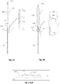
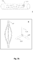
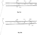
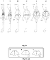
- FIG. 2a depicts exemplary lateral and superior views of slit tubes having 3 (ii) , 4 (iii) and 6 (iv) radially expandable members 1.31, 1.32, 1.33, 1.34, etc.
- Different heat-set tooling can produce any kind of three dimensional structure (e.g., Fig. 2 sub i), ellipsoidal, ellipsoid hyperboloid, ovoid, trapezoid, spherical, disciform or any combination thereof, depending on the interior of the surface that needs to be conformed with.
- ellipsoid paraboloidal is particularly useful in cases where a stent member needs to conform to a central smaller diameter.
- the members need to be more compliant this can be achieved by a number of methods: smaller member thickness in certain areas ( Fig. 2a , 2 . 1 ), smaller slits or larger member widths in certain areas ( Fig. 2b , 2.2 ), localized electropolishing, localized etching or by using more elastic filaments in some areas compared to others.
- the longitudinal member sizes, strengths and lengths are selected so as to able to sustain and if necessary oppose the elastic recoil applied on the frame or stent from the surrounding tissue. They may have the same length in order to be able to collapse completely and expand symmetrically.
- the members of multi-part frames or stents may be attached by adhesive, solder, spot welding, brazing, crimping, welding or any other joining method suitable for joining the edges of an intravascular stent.
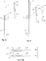
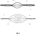
- Wire twists, braids and mesh combinations need not to have a low flow profile upon expansion in order to allow the bodily fluid to flow through. But as a general rule the members (strips, wires or tubes) have a low flow profile between the points of the minimum and maximum diameter of the device, i.e., between the diameters of collapsed and fully deployed stages. Fig.
- FIG. 2c shows two exemplary stent members (i) and (ii) comprising wire twists in deployment status.
- the monofilaments comprising the struts remain perplexed as they diverge from their proximal tubular portion 2.3, split into single filaments 2.4 or smaller filament groups 2.5 to form the middle (or expandable) portion, and converge again to reform or connect to the distal tubular portions 2.3.
- Fig. 2c (i) and (ii) show exemplary wire twist stent members.
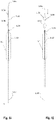
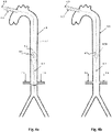
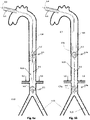
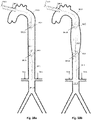
- Figs. 1a through 1o show non-claimed illustrative examples in which frames 1.3 are expanded in conjunction with deployment of a pumping balloon 1.1 carried by the balloon catheter 1.20.
- the frames will be described in relation to the balloon 1.1 as proximal if they are positioned more toward the catheter end extending freely outside of the body, and distal if they are positioned more toward the catheter end positioned within the circulation limen. They are further divided to upper (more distal) and lower (more proximal), when more than one proximal or distal stent members are described.
- a proximal expandable frame 1.3 is delivered in a collapsed state, mounted on an elongated shaft 1.2.
- the expandable frame 1.3 comprises the distal portion of the shaft, which is advanced through the balloon's insertion site and operated from out of the body, surrounding the balloon catheter 1.20.
- the shaft is inserted separately to the balloon and pushed against a stopping element 1.86 that surrounds the balloon catheter 1.20; the expandable frame 1.3 is pretreated, heat set, and biased to obtain an ellipsoid configuration upon expansion, and thus longitudinal sliding 1.4 is transformed to radial expansion ( Fig. 1b ).
- the stopping element 1.86 may be as simple as a widened balloon catheter portion with a diameter slightly larger to the outer surface of the shaft 1.2 or a small caliber, hollow tube fixed onto the desired position of the balloon catheter 1.20.
- the shaft may comprise a hollow tube made from a reasonably flexible biocompatible plastic material or a metal superelastic material such as Nitinol alloy S. Examples of such plastic materials are biocompatible polypropylene, polyethylene, PVC, silicone, polyurethane, polystyrene and combinations thereof.
- a sleeve tube ( Fig 1 sub i, 1.87) having an inner diameter larger than the outer diameter of the expandable frame 1.3, may be used to reduce the flow profile of the shaft and stent member during insertion.
- the applied force/longitudinal shortening (F/dL) relationship curve may be continuously monitored using an electronic interface connected to an external control handle and a potentiometer applying the force to the proximal portion for the sliding of the shaft 1.2.
- the interface may display continuously in a graphical or numerical manner the applied force for a given longitudinal motion, and the zero point may be the moment the shaft 1.2 reaches the stopping element 1.86.
- the inventors have determined that there is a curve point where more force is needed to achieve more expansion and this is may be different for each stent member size and circulation lumen.
- An electronic automatic system may be used to apply longitudinal force and detect substantial deviation from the relationship curve indicating contact between the expandable frame and the walls of the vessel or cavity, allowing expansion up to contact or a maximum desired diameter.
- gradation markers and indices reflecting the actual diameter of the stent member may be printed upon the balloon catheter portion 1.20, where the proximal portion of the shaft is rested outside of the body, so that the operator may be aware of the expanded diameter.
- manual opening up to a predetermined diameter may be used in cases where the circulation lumen wall is able to sustain small expansion forces without significant risk for perforation.
- the balloon tip 1.23 is here shown to include a lumen 1.22 that runs through the balloon's entire length.
- This lumen which is often described a pressure sensor tube, is known to those familiar with the art.
- the standard design of an IAB incorporates a balloon catheter 1.20 that carries gas in and out of a balloon 1.1 attached to it at a proximal junction point 1.21.
- Within the balloon catheter 1.20 there is usually a second lumen (shown as 1.22) that originates at the proximal end of the balloon catheter, courses the entire length of the balloon catheter and actual balloon up to the balloon tip 1.23.
- this second lumen 1.22 gains access to the circulation.
- this second lumen is commonly referred to as "pressure line” or “pressure sensor line” or “pressure tube”.
- this second lumen is also routinely used to thread a guiding wire.
- a lumen like a pressure-sensor lumen is still provided to support the balloon 1.1 along its length and prevent longitudinal folding of the balloon during inflation/deflation, as well as to provide a path for a guiding wire.
- both lumens as intra-balloon lumens 1.22, where pressure sensing may or may not be provided in some implementations of the apparatus.
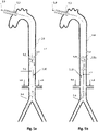
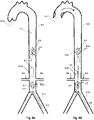
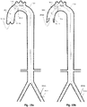
- Figs. 1c and d show a variation of the system shown in Figs. 1a and 1b .
- the expandable frame 1.3 has its distal shaft portion 1.77 joined to the exterior of the balloon catheter 1.20 at a desired position. Preferred joining methods are welding, molding, adherence with glue, or any other method suitable for joining the edges of two plastic portions or plastic/metal portions, or metal portions.
- the expandable frame 1.3 is pretreated, heat set, biased to obtain an ellipsoid configuration upon expansion, conforming the interior of the body channel.
- the final diameter may be either achieved passively, automatically upon release of the shaft 1.2, being the natural heat set position upon release of the shaft, or be subsequent to active longitudinal sliding of the shaft.
- Fig. 1 sub ii corresponds to the addition of a sleeve tube 1.87 that may be used to keep the expandable frame restrained to reduce the device's profile and facilitate insertion.
- the balloon catheter 1.20 incorporates a stopping element 1.79 positioned within the expandable frame 1.3 so that it becomes abutted against the proximal shaft portion of the expandable frame 1.3 to prevent excessive travel thereof and limit expansion to a predetermined diameter.
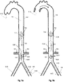
- Figs. 1e and f show another variation of the system.
- the expandable frame 1.3 has its distal shaft portion 1.77 joined to the balloon catheter 1.20 and is heat set to deploy spontaneously to a predetermined diameter, with deployment controlled via operating wire(s) 1.18 attached or joined to the proximal portion thereof.
- An intermediate diameter can be achieved by pulling or releasing the wire.
- the operating wire is ideally run through a lumen of a multi-lumen balloon catheter 1.20, or external hollow tubes attached upon a single lumen balloon catheter, having its proximal end outside the body operated by the user and its distal end attached to the proximal shaft portion of the expandable frame 1.3.
- a variety of intermediate diameters can be produced by pulling or releasing the operating wire(s) 1.18.
- the expandable frame 1.3 is completely expanded when the operating wire 1.18 is inserted (if manually expanded) or released (if self-expanding) and completely collapsed when the operating wire is pulled.
- a sleeve tube 1.87 or a similar sleeve tube not extending over the expandable frame 1.3 may extend outside the body, preferably proximate the proximal end, to create the multi-lumen structure.
- Fig. 1 sub iv and Fig. 1 sub v show the sleeve tube 1.87 and stopping element 1.79 variations mentioned before.
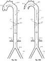
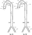
- Figs. 1g and 1h represent another non-claimed illustrative example.
- An expandable frame 1.3 is mounted on a segment 1.24 extending distally from the pumping balloon, e.g. a balloon tip portion 1.23 connected to an intra-balloon lumen 1.22, or an inter-balloon catheter portion (described further below and shown in Figs. 13a, 13b , and 20 .
- Both comprise hollow tube portions (one lumen or multi-lumen), positioned distally in relation to at least one inflatable balloon 1.1, and are structurally similar to the lumen of the balloon catheter 1.20.
- the segment 1.24 has defined proximal and distal end portions, in terms of proximity to the balloon or insertion site, and may accommodate at least one expandable frame 1.3.
- the expandable frame 1.3 has its proximal shaft portion 1.81 joined to the balloon tip 1.23 and/or segment 1.24, with its distal shaft portion 1.77 free to move about and to reversibly slide along the axis of the segment, between a collapsed ( Fig. 1g ) and deployed ( Fig. 1h ) configuration.
- the intra-balloon lumen 1.22 is shown to accommodate a linearly movable operating member 1.18 , with an outer diameter smaller than the inner diameter of the intra-balloon lumen.
- the operating member 1.18 may comprise a linearly movable operating wire or tube ( Fig 1l , 1m ) which may have a widened end forming, or otherwise be joined to, an end-cap 1.17.
- the end cap 1.17 is operatively coupled to the distal end of the expandable frame 1.3 for deployment.
- the operating member 1.18 may be made from a reasonably flexible biocompatible plastic material or a metal elastic material, preferably superelastic such as Nitinol alloy S. Examples of such plastic materials are biocompatible polypropylene, polyethylene, PVC, silicone, polyurethane, polystyrene and combinations thereof.
- the end cap 1.17 is shown to have a diameter larger than the inner diameter of the expandable frame's distal shaft portion 1.77 in order to engage with it and induce expansion upon pulling.
- the operating wire 1.18 may be fixed to the distal shaft portion of the expandable frame.
- Preferred joining methods are welding, molding, adherence with glue, or any other method suitable for joining the edges of two plastic portions or plastic/metal portions or metal portions.
- the incorporation of an expandable frame 1.3 at the distal end of the apparatus poses a challenge to bending during percutaneous insertion.
- a sleeve tube 1.87 ( Fig 1 sub vi) having an inner diameter larger than the outer diameter of the expandable frame 1.3 and collapsed pumping balloon 1.1 may be used to reduce the flow profile of the expandable frame and pumping balloon during insertion.
- FIG. 1 sub vii show the sleeve tube 1.87 and stopping element 1.79 variations mentioned before, however in this and similar embodiments the stopping element is positioned within the expandable frame 1.3 so that it becomes abutted against the distal shaft portion of the expandable frame 1.3 to prevent excessive travel thereof and limit expansion to a predetermined diameter.
- the balloon apparatus is shown being assembled in a step wise manner at the operation site, having its distally positioned, expandable frame 1.3 separate from the balloon 1.1 and balloon catheter 1.20.
- a transcutaneous hollow needle provides access to the circulation lumen, or a channel communicating to it; a guiding wire 1.47 is fed through the needle and advanced to the operation site. The needle is removed whilst the guiding wire remains in situ.
- a hollow elongated shaft 1.45 integrating the expandable frame 1.3 at its distal end, is inserted through the puncture site, advances and slides over the guiding wire until it is delivered to the operation site.
- the pumping balloon 1.1 is positioned by sliding it down the elongated shaft 1.45 after threading the elongated shaft through the intra-balloon lumen 1.22 (and, if the intra-balloon lumen is not contiguous to the outside of the body, with a non-gas-pumping lumen of a multi-lumen balloon catheter 1.20).
- Both the shaft 1.45 integrating the expandable frame 1.3 and the balloon 1.1/balloon catheter 1.20 combination have sufficient lengths so as to be accessible from outside the body.
- the expandable frame 1.3 is expanded.
- This assembly method provides a great advantage: if the expandable frame 1.3 includes a check valve, occlusion device, or other function-enhancing structure, that may increase the diameter of the expandable frame to such an extent that it cannot be threaded through an intra-balloon lumen 1.22. In these cases this method of insertion and assembly is preferable.
- the expandable frame 1.3 Two expansion methods of the expandable frame 1.3, an induced-one and a self-expanding one, will be described.
- the elongate hollow shaft 1.45 integrating the expandable frame 1.3
- a stopping element 1.46 By stopping element in this case is meant a widened end of the guiding wire 1.47 or an end cap joined to the end of the guiding wire.
- the expandable frame 1.3 is pretreated and heat set, to obtain a biased ellipsoid configuration upon expansion.
- the inner diameter of the expandable frame 1.3 is less than the outer diameter of the stopping element 1.46.
- the shaft 1.45 is advanced through the balloon's insertion site, surrounding the guiding wire 1.47, and operated from outside of the body.
- a sleeve tube may be used to facilitate insertion of the shaft 1.45 and to restrain the integrated expandable frame 1.3 from deploying.
- the stopping element 1.46 Upon reaching the stopping element 1.46, further longitudinal sliding toward the stopping element is transformed to radial expansion of the expandable frame 1.3.
- the widened end of the guiding wire 1.47 and the elongate hollow shaft 1.45 may be fixed together at their distal ends and advanced to the operation site as a unit.
- Preferred joint methods are welding, molding, crimping, adherence with glue, or any other method suitable for joining the edges of two plastic portions or plastic/metal portions, or metal portions.
- the hollow shaft 1.45 operated from outside the body, slides freely over the guiding wire 1.47 and the expandable frame 1.3 expands when pushed against the fixed-together ends.
- the expandable frame 1.3 on the elongated hollow shaft is pretreated to deploy to a predetermined desired diameter.
- the distal ends of the hollow shaft 1.45 and guiding wire 1.47 may slide freely to be fixed together.
- An outer sleeve tube 1.87 like that shown in Fig. 1 sub ii, may be manipulated for delivery and deployment control.
- the outer sleeve tube 1.87 has an inner diameter larger than the outer diameter of the expandable frame 1.3 and elongate shaft 1.45 (substituting for the balloon catheter 1.20 of the cited figure).
- the elongate shaft and sleeve tube are hollow structures comprising of a reasonably flexible biocompatible plastic material or a metal material, preferably superelastic Nitinol, such as Nitinol alloy S.
- plastic materials are biocompatible polypropylene, polyethylene, PVC, silicone, polyurethane, polystyrene and combinations thereof.
- the intra-balloon lumen 1.22 has an inner diameter larger than the outer diameter of the expandable frame 1.3 and elongate shaft 1.45, during removal of the balloon apparatus the intra-balloon lumen may be used as a sleeve tube.
- the stopping element 1.46 may again be a widened end of the guiding wire 1.47 or an end cap joined to the end of the guiding wire. In either case, for either of the above methods, the stopping element 1.46 needs to have a sufficiently small diameter to threat through a needle or obturator during percutaneous insertion.
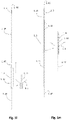
- Figs. 1i and 1j show to a non-claimed illustrative example with two distal expandable frames, 1.3a and 1.3b, fixed on the balloon tip portion 1.23 of a pumping balloon 1.1, following induced expansion.
- the expandable frames are initially in the collapsed state, but pretreated to acquire a biased shape upon expansion.
- Pulling of the guiding wire 1.47 abuts a stopping element 1.46 against the upper or distal-most expandable frame 1.3a, which is induced both to expand and slide towards the balloon tip 1.23.
- the latter longitudinal motion abuts the upper expandable frame 1.3a against the lower expandable frame 1.3b, which is eventually also forced to expand.
- the final diameter of each stent member can be predetermined by incorporating stopping elements 1.79 like those described earlier on the balloon tip portion 1.23.
- Fig 1k depicts an exemplary combination of distal and proximal expandable frames 1.3.
- Each one can be separately controllable as described above, being self-expandable or induced-expandable.
- the proximal expandable frame 1.3c is integrated in a hollow shaft 1.2 and forced to expand due to the longitudinal sliding 1.4 of the shaft with respect to the balloon catheter 1.20.
- the distal expandable frame 1.3d is in an initial collapsed state and forced to expand due to longitudinal pulling 1.42 of the operating member 1.18 or guiding wire 1.47, in accordance with the alternatives described above.
- the distal expandable frame 1.3d is fixed on the balloon's tip 1.23 and traction of the member or wire engages the respective stopping element 1.17 or 1.46 with the distal shaft portion of the expandable frame, forcing it to expand.
- Figs. In and 1o show a preferred controlled expansion combination of two distal expandable frames 1.3a and 1.3b and a proximal expandable frame 1.3c mounted upon a balloon apparatus on either side of a pumping balloon 1.1.
- All stent members 1.3a, 1.3b and 1.3c comprise self-expanding frames predetermined to expand up to a desired diameter. They are delivered in a collapsed state, Fig In, and they are restrained by a sleeve tube 1.51.
- the expandable frames have their proximal portions 1.81 joined to a balloon tip portion 1.24, whereas their distal ends are free to slide along the balloon tip portion 1.24. Controlled and reversible expansion is achieved by withdrawal 1.57 of the surrounding sleeve tube 1.51. Stopping elements 1.79, shown in Fig. 1 sub viii and Fig. 1 sub ix and described above, may be included to limit expansion to desired predetermined diameter.
- Figures 4-20 illustrate various general apparatus configurations and applications. It will be understood that the devices discussed below may include some or all of the features and details discussed above, as claimed, but are being discussed at a high level of generality for the convenience of the now-informed reader.
- the expandable frames discussed may lack any check valve or occlusion device feature, serving only to center adjoining portions of the apparatus, or may include a check valve feature providing unidirectional flow for the purposes described herein, or may include a occlusion device feature serving at least in part to compartmentalize or partition flow and pressure assist as described herein.
- examples like those shown in Figs. 1a through 1o may be used in applications like those shown, e.g., in Figs.
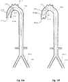
- Figs. 4a and 4b show views of an exemplary IAB combining an IAB including a pumping balloon 4.1 carried by a balloon catheter 4.9 with a proximal expandable frame 4.2 including a distally-opening check valve 4.5. It is inserted through the aortic cannulation site 4.3, into the aorta 4.8, during Cardiopulmonary By-Pass (CPB).
- the IAB may operate either in counterpulsation mode, gated with a pulsatile CPB pump, or non-gated in internal pacing mode, combined with a continuous flow CPB pump, to provide pressure assist to the lower aorta 4.10, the renal arteries 4.6, and other peripheral arterial flows.
- the proximal end of the balloon catheter 4.9 remains outside the body.
- An important advantage of the system is that can be used to increase the blood pressure and flow in any part of the circulation during CPB (celiac arteries, carotids, renal arteries, etc.). In this case it is used to augment pressure and flow in the renal arteries 4.6 through operation of a proximal, passive, and distally-opening unidirectional valve, preventing upstream flow (opposite to CPB flow) as shown.
- the valve 4.5 opens and closes periodically in conjunction with the balloon pumping.
- the valve opens ( Fig. 4b ) when downstream flow originating from the CPB forces the leaflets 4.5a, 4.5b, etc. to open, and vice versa closes ( Fig 4a ) when pressure and upstream flow originating from the balloon's pumping exceeds the blood pressure 4.7 on the proximal side of the valve.
- the exact positioning of the expandable frame 4.2 in relation with the renal arteries 4.6 remains to be ascertained. However it is anticipated that: the best position of the expandable frame 4.5 will be 4-5 cm upstream from the renal arteries, and the best position for the distal end of the balloon is likely 1-2 cm below the renal arteries.. These help both to minimize retrograde flow from the renal arteries during the balloon's deflation, and to optimize blood pooling and flow towards the renal arteries without balloon itself impeding the flow.
- this application is expected to reduce dramatically the size of the balloon 4.1 and subsequently the size of the balloon catheter 4.9 needed to achieve the same pressure effect in the renal arteries in comparison with the current conventional IAB.
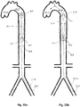
- Figs. 5a and 5b depict another non-claimed illustrative example. It integrates an additional, distal expandable frame 5.4 for better centering and fixing of a 'renal' IAB.
- the distal expandable frame 5.4 when fully expanded, can be used solely to space the balloon 5.1 in the center of the abdominal aorta 5.8, thereby avoiding balloon-to-wall contact.
- the expandable frame 5.3 is shown to integrate occlusion device 5.14, such as a membrane attached to the inner surface 5.13, or any portion thereof, of the frame members.
- This membrane 5.14 is made of a biocompatible material (such us TEFLON, DACRON, polyethylene, polyamide, nylon, polyurethane, natural rubber, synthetic rubber, thermoplastic elastomer or thermoset polymer and the like) with anti-thrombotic properties.
- Expansion of the distal expandable frame 5.4 induces a twofold advantage: 1. a partial downstream flow obstruction which augments retrograde flow to the renal arteries 5.6 and 2. a prevention of retrograde flow from more peripheral sites 5.15 which reduces 'steal phenomenon' from the periphery thereby increasing blood flow in the lower aorta 5.10 between the respective expandable frames 5.2 and 5.4. The latter contribution maximizes the induced pressure and flow effect of the balloon 5.1 in the aortic portion where the renal arteries 5.6 originate.
- distal expandable frame 5.4 could combine with any other occlusion device.
- An inflatable occlusion balloon of a diameter between 0.5-2.5 cm, residing within, below, or above (as claimed) the distal expandable frame 5.4, would occlude partially the downstream flow and serve equally the same purposes of an occlusion device, thereby localizing and maximizing the pressure and flow effect between this valve/balloon and the proximal expandable frame 5.2.
- This same apparatus in a smaller version, is particularly useful in the cases where a cerebral artery is ruptured in the course of a bleeding stroke.
- selective lateral branch augmentation perfusion analogous to selective perfusion of the renal arteries 5.6, is likely warranted to compensate the lack of perfusion via collateral vascular routes.
- the device is fed collapsed and percutaneously inserted to a position upstream of the bleeding area and the occlusion device 5.14 is deployed.
- the pumping balloon 5.1 starts to operate in non-gating mode.
- the upstream (as shown, distal) check valve 5.5 opens and vacuums blood into the lumen surrounding the pumping balloon.
- the upstream check valve 5.5 closes and the blood is ejected towards the lateral branch 5.6a.
- the rate and volume of the balloon inflation cycles determine the desired output.
- a 'renal' IAB is combined with a proximal expandable frame 6.2 including a distally-opening check valve 6.5 and a distal expandable frame 6.2 including a distally-opening check valve 6.5. As in the prior examples it is inserted through the aortic cannulation site 6.3, during Cardiopulmonary By-Pass (CPB).
- CPB Cardiopulmonary By-Pass
- the pumping balloon 6.1 is in deflation, the proximal check valve 6.5 on expandable frame 6.2 is open and allows downstream flow from the LV and upper aorta 6.7, and the distal check valve 6.5 on expandable frame 6.4 is closed to prevent upstream retrograde flow from more peripheral sites 6.15, which again reduces 'steal phenomenon' from the periphery.
- the pumping balloon 6.1 is inflated, the proximal check valve 6.5 on expandable frame 6.2 is closed to prevent upstream retrograde flow from the lower aorta 6.10, and the induced flow is isolated within the lower aorta 6.10 and that way directed towards the renal arteries 6.6.
- Distal check valve 6.5 on expandable frame 6.4 is open and allows downstream flow.
- the distal expandable frame 6.4 could also include a occlusion device such as the membrane 5.15.
- the occlusion device would occlude partially the downstream flow and thereby produce greater pressure assist in the renal arteries 6.6 (while reducing pressure assist to more peripheral sites 6.15).
- a second distal expandable frame, upper or lower with respect to the distal expandable frame 6.4 may provide this feature while simplifying manufacturing of the respective expandable frames.
- Figs. 7a and 7b , 8a and 8b , and 9a and 9b depict other illustrative examples where the entry site of the IAB is the traditional femoral access 7.11, 8.11, and 9.11, respectively, and the IAB is gated with the aortic valve 7.12, 8.12, and 9.12 respectively, in counterpulsation mode.
- the current invention can be used to augment pressure and blood flow in any branches of the lower (abdominal) and upper (thoracic) aorta, an exemplary emphasis will continue to be given to the renal arteries and lower aorta where they originate.
- Figs. 7a and 7b show to views of an IAB, inserted through the femoral artery 7.11, aiming to increase the renal flow in a patient e.g. with pre-renal failure secondary to low cardiac output.
- the pumping balloon 7.1 is combined with a distal expandable frame 7.4 having a proximally-opening unidirectional valve, check valve 7.5, allowing downstream flow only.
- check valve 7.5 proximally-opening unidirectional valve
- Fig. 7b the aortic valve 7.12 is open, the pumping balloon 7.1 is in deflation, and check valve 7.5 is open and allows downstream flow.
- Fig. 7a the aortic valve 7.12 is closed, the pumping balloon 7.1 is inflated, and check valve 7.5 is closed, thereby 'isolating' the pressure augmentation effect in the lower aorta 7.10 below the valve, where the renal arteries 7.6 originate.
- the IAB is combined with a proximal expandable frame 8.2 including a proximally-opening check valve 8.5 and a distal expandable frame 8.4 including a distally-opening check valve 8.5.
- the aortic valve 8.12 is open, the pumping balloon 8.1 is in deflation, the distal check valve 8.5 on expandable frame 8.4 is open and allows downstream flow; and the proximal check valve 8.5 on expandable frame 8.2 is closed, preventing upstream retrograde flow and thereby increasing the 'vacuum effect' and pooling of blood in the lower aorta 8.10 where the renal arteries 8.6 originate.
- aortic valve 8.12 is closed, the balloon pump 8.1 is inflated, the distal check valve 8.5 on the expandable frame 8.2 is closed and prevents upstream flow to any other arteries apart from the ones below that expandable frame, and the proximal check valve 8.5 on the expandable frame 8.4 is open thereby allowing increased pressure and flow towards the lower limbs.
- the IAB is combined with a proximal expandable frame 9.2 including a occlusion device 9.14 and a distal expandable frame 9.4 including a distally-opening check valve 9.5.
- the occlusion device may comprise a membrane 9.14 attached to the inner surface 9.13 of the expandable frame 9.2.
- a similar occlusion device could be an inflated occlusion balloon, positioned at the same level.
- the occlusion device 9.14 provides a twofold advantage: 1. a partial downstream flow obstruction which augments retrograde flow to the renal arteries 9.6 and 2. a prevention of retrograde flow from more peripheral sites 9.15 which reduces 'steal phenomenon' from the periphery thereby increasing blood flow in the lower aorta 9.10 between the respective expandable frames 9.2 and 9.4.
- Figs. 10a and 10b illustrate an exemplary IAB (not claimed) including a pumping balloon 10.1 combined with a single expandable frame 10.2 placed at its proximal end.
- This proximal expandable frame 10.2 shown in an expanded state, is carrying a proximally-opening unidirectional check valve 10.5.
- semi-lunar leaflets 10.5a and 10.5b originating from an annular portion of the expandable frame 10.2 are depicted.
- the leaflets of the check valve are thin, supple and move easily from the completely open position (when the pumping balloon 10.1 inflates) to the closed position (when the pumping balloon 10.1 deflates).
- the aorta 10.8, the aortic valve 10.12, and renal 10.6 and common iliac/femoral arteries 10.11 are shown.
- the exact positioning of the expandable frame 10.2 in relation with the renal arteries 10.6 remains to be ascertained. However it is anticipated that the best position of the expandable frame 10.2 will be 4-5 cm just above the renal arteries. This helps to prevent retrograde flow from the renal arteries during the balloon's deflation, and yet allow downstream flow towards the renal arteries 10.6 without impeding the flow.
- the doctor may evaluate the exact positioning by looking at an image produced by an angiogram with contrast injection performed after the insertion of the system. Ideally, contrast agent injected below the check valve 10.5 of the expandable frame 10.2, shouldn't reach the upper aorta 10.7 above the check valve 10.5.
- Figs. 11a and 11b and 12a to 12c illustrate two other examples related to the apparatus shown in Figs. 10a and 10b , incorporating a femorally inserted 11.11, 12.11 apparatus, upper proximal expandable frames 11.2a and 12.2a, respectively, having proximally-opening check valves 11.5 and 12.5, respectively, and pumping balloons 11.1 and 12.1, respectively, operating in counterpulsation mode, but additionally lower proximal expandable frames 11.2b and 12.2b, respectively, which function as selectively deployable blocking elements.
- Figs. 11a , 11b , 12a , and 12b show the deployed configurations
- Fig. 12c shows the collapsed, 'normal state' configuration.
- the former example, 11.2b integrates a 'complete' blocking element, i.e. a distally-opening unidirectional check valve 11.5, while the letter integrates a occlusion device 12.14 providing partial blocking, such as a continuous membrane mounted thereupon or an inflatable occlusive balloon.
- the lower proximal expandable frame 11.2b, 12.2b is deployed to at least partially block the downstream flow (at 11.9, 12.10). That way the limited cardiac output and the pressure generated from the heart is used momentarily to perfuse the upper part of the body, the brain and the heart, until cardiac output is restored.
- Figs. 13a and 13b depict a preferred embodiment for increasing aortic pressure in a specific compartment of the aorta 13.8, with the embodiment incorporating a pumping balloon 13.1 fluidically connected to more proximal bi-directional valve 13.25 , such as an occlusive balloon, according to the invention as claimed.
- Fluidically connected bi-directional valves specifically assist balloons to IAB
- IAB Fluidically connected bi-directional valves
- this pressure split relies on the proximity of the assisted balloon to the vessel wall. It is easily understood by those familiar with the art that close proximity predisposes to aortic wall trauma. Subsequently there is a fine balance between pressure effect compartmentalization and aortic wall trauma, making it apparently impossible to achieve both.
- proximal expandable frame 13.2 including a distally-opening, unidirectional check valve, proximate the bi-directional valve 13.25 and interposed between the bi-directional valve 13.25 and the pumping balloon 13.1.
- This proximal expandable frame 13.2 conforms precisely the interior of the Aorta and centralizes the bi-directional valve balloon 13.25 within the aorta 13.8.
- the check valve 13.5 on the interposed expandable frame 13.2 closes and prevents retrograde flow.
- the check valve 13.5 on the interposed expandable frame 13.2 would normally open.
- the close proximity of the bi-directional valve balloon 13.25 to the proximal side of the check valve 13.5 compared to the pumping balloon 13.1, creates locally higher pressure which either prevents or delays opening of the interposed check valve.
- a variety of bi-directional valve balloon volumes and distance relationships can be used in order to predetermine the interposed check valve's opening delay. Both the distance and balloon volume determine local pressure augmentation and check valve closure delay/opening timing. It is important to understand that the proximal bi-directional valve 13.25 is an alternative to the lower proximal expandable frame 12.2b shown in Figs 12a and 12b .
- Figs. 14a and 14b , 15a and 15b , and 16a and 16b show non-claimed illustrative examples particularly useful in enforcing pressure and flow in peripheral parts of the circulation.
- the apparatuses will be described in conjunction with methods of venous flow and carotid flow augmentation. Despite that, it must be understood that usage is not restricted to these cases, as the apparatuses and methods have a wider range of clinical applicability in circulatory lumens generally.
- Figs. 14a and 14b show a circulatory assist apparatus including a pumping balloon 14.1 and one proximal expandable frame 14.2 including a distally-opening, unidirectional check valve 14.5.
- This system may be used when pressure increase in a body cavity or vessel is more important compared to axial flow such as the in the cases where stenoses exist in several arterial branches originating from a main artery.
- the flow increase in the main artery doesn't necessarily generate flow increases in all arterial branches given the fact that higher flow will occur mainly in the non-stenotic branches.
- pressure increase is more appropriate means of increased perfusion.
- the pressure drop causes the proximal check valve 14.5 to open and allow flow into the arterial space surrounding the balloon. Subsequently when the pumping balloon 14.1 inflates the proximal check valve 14.5 closes and the pressure and flow increase on the distal side of the check valve 13.5.
- the pressure increase is proportional to the balloon displacement volume.
- Figs. 15a and 15b illustrate a preferred circulatory assist apparatus, inserted through a peripheral artery, incorporating two expandable frames, a proximal expandable frame 15.2 and a distal expandable frame 15.4, each including a distally-opening, unidirectional check valve 15.5, and a pumping balloon 15.1 therebetween.
- the apparatus enhances blood flow towards its distal end, opposite to the insertion site.
- the apparatus could be for instance inserted in the upper portion of the jugular vein and advanced towards the heart.
- the proximal check valve 15.5 on expandable frame 15.2 is open, and the distal check valve 15.5 on expandable frame 15.4 is closed, vacuuming, in the described instance, venous blood from the brain.
- the proximal check valve 15.5 on expandable frame 15.2 closes, the distal check valve 15.5 on expandable frame 15.4 opens, and the blood is ejected, in the described instance, towards the right atrium.
- the apparatus is used to enhance venous flow, gating in counterpulsation is not needed.
- small or big balloon volumes and fast or slow inflation rates can be used.
- small balloons in high pumping frequencies may be advantageous in order to prevent stasis and thrombogenesis.
- the balloon volume is sufficient to achieve a pressure increase adjacent the pumping balloon 15.1 above the pressure of the distal site 15.16, in every inflation cycle, in order for blood to be ejected.
- Figs. 16a and 16b depicts a variant where the orientation of the unidirectional check valves 16.5 with respect to the apparatus and insertion site are reversed. It is apparent that reverse flow assist apparatuses can be used to achieve fluid vacuum from a body vessel or body cavity, and can be inserted via a distal site and advanced towards the area of deployment. This system can be inserted percutaneously, for example via the femoral vein and advanced upwards into the jugular vein for deployment. In such instances the blood is ejected towards the balloon catheter 16.9 and insertion site, on the proximal sides of the check valves 16.5. When the pumping balloon 16.1 deflates, the distal check valve 16.5 on the expandable frame 16.4 opens and blood is vacuumed into the space between the expandable frames 16.2, 16.4 adjacent the pumping balloon.
- Figs. 17a and 17b depict another non-claimed illustrative example as well as a method of using with a system including expandable-frame-mounted check valve and blocking elements for selectively increasing the blood flow and pressure in a specific compartment of the arterial circulation.
- the apparatus may be inserted through an incision made upstream or downstream from a selected position, with the relative position of the expandable frames (proximal and distal), relative orientation of the check valves (distally-opening and proximally-opening), and relative placement of the blocking element (within the distal or proximal expandable frame) varying appropriately as described earlier above.
- the apparatus may sequentially integrate a distal expandable frame 17.4 including a proximally-opening check valve 17.5 , , a pumping balloon 17.1, preferably operated in counterpulsation mode, a proximal expandable frame 17.2a including a proximally-opening check valve 17.5, and a more proximal expandable frame 17.2b including a occlusion device 17.14 or other blocking element.
- a distal expandable frame 17.4 including a proximally-opening check valve 17.5 preferably operated in counterpulsation mode
- a proximal expandable frame 17.2a including a proximally-opening check valve 17.5
- a more proximal expandable frame 17.2b including a occlusion device 17.14 or other blocking element.
- the distal check valve 17.5 on the expandable frame 17.4 is a unidirectional 'downstream' valve that defines the most upstream point where pressure augmentation occurs. This may have clinical significance if, for example, one wants to augment flow in the left common carotid artery but not the right subclavian artery. This may be needed in a case where the left common carotid artery is stenotic producing an evolving stroke.
- the proximal check valve 17.5 on the expandable frame 17.2a is also a unidirectional 'downstream' valve that closes with balloon deflation, prevents retrograde flow from below the balloon 17.1, and increases blood flow from above, such as from the LV.
- proximal check valve 17.5 is sufficient to prevent retrograde flow, it is not sufficient to compartmentalize the aorta 17.8 and prioritize for pressure augmentation compartmentalization, e.g., above the lower extremities.
- a second expandable frame 17.2b including a blocking element is used.
- the level of the blocking element defines the lower limit where pressure increase mainly occurs.
- the degree of expansion of the blocking element defines the pressure ratio between the compartmentalized space above and uncompartmentalized space below the blocking element.
- Figs. 17a and 17b illustrate an exemplary implementation where the apparatus is used to increase the blood pressure in an aortic compartment extending from the Aortic Arch 17.17 to the lower aorta 17.10, aiming to prioritize a flow increase towards the brain and renal arteries 17.6, thus the more proximal expandable frame 17.2b is placed under the renal arteries. It has a particular use in ischemic stroke and renal failure patient.
- the pumping balloon 17.1 deflates just prior to the aortic valve 17.12 opening to assist the LV to eject blood out.
- the proximal check valve 17.5 on the expandable frame 17.2a closes because of the pressure fall and the distal check valve 17.5 on the expandable frame 17.4 opens allowing the balloon to vacuum blood out of the heart.
- the upper valve closes 17.2, the lower valve 17.4 opens 17.9 and the blocking element 17.3 directs the flow towards the renal arteries 17.6.
- Figs. 18a and 18b depict a variation of the apparatus shown in Fig. 4 .
- This more proximal check valve 18.5 prevents direct pressure transfer to the cannulation site when the pumping balloon 18.1 inflates.
- the apparatus of this embodiment can be used to increase the blood pressure and flow in any part of the circulation during CPB.
- Both the lower proximal check valve and upper proximal check valve 18.5 in the respective expandable frames 18.2a and 18.2b are unidirectional 'downstream' valves.
- Deflation of the pumping balloon 18.1 draws blood into the aorta 18.8 which forces the respective valves to an open configuration.
- expansion of the balloon pushes blood downstream, e.g., into the renal arteries 18.6, but also upstream which temporarily closes the upper proximal valve 18.5 on expandable frame 18.2a and therefore impedes retrograde flow.
- This pressure effect may be transmitted as a rebound wave to the aortic insertion site 18.3 and damage the cannulation point, i.e., rupture of the tissue around the cannulation point.
- the more proximal check valve 18.5 on the lower proximal expandable frame 18.2b prevents the direct pressure transmission to the insertion site 18.3 and causes part of the upper aorta 18.7 between the proximal expandable frames 18.2a, 18.2b to dilate, behaving as a buffer chamber, which prevents acute pressure changes.
- Figs. 19a and 19b , and 19c and 19d illustrate additional illustrative examples and the basic advantage of the disclosed system. It is generally desirable to position the pumping balloon 19.1 as close as possible to the left ventricle (LV) so as to more efficiently induce a 'vacuum effect.' However under 'normal circumstances' a straight pumping balloon cannot be placed in the aortic arch 19.17 or any other curved vessel. The pumping balloon would traumatize the aortic wall during inflation, because of a 'whipping' phenomenon, attributed mainly to continuous balloon movement during inflation/deflation, the fact that the straight pumping balloon cannot fit in the aortic arch's curvature after inflation, and secondary turbulent flow.
- LV left ventricle
- Figs. 19a and 19b show an apparatus (not claimed) having smaller size and diameter pumping balloon 19.1 that has been advanced in the ascending aorta through a peripheral artery, such as a femoral artery site 19.11.
- the pumping balloon may have an inflated diameter of 12-30 mm and a length of 35-90 mm depending upon patient's size (1.5-1.90 m).
- the pumping balloon shape may be spheroid, oval, cylindrical or any combination thereof.
- a typical pumping balloon of this size wouldn't be able to produce any significant vacuum effect, as blood would be vacuumed also from the brain vessels and other arterial branches from the aortic arch 19.17 (a phenomenon that can be described as 'steal flow') towards the ascending aorta 19.18.
- the balloon preferably operates in a gated, counterpulsation mode, but it can equally effectively operate in a non-gated mode if the cardiac output drops to zero, as it occurs in the context of a cardiac arrest.
- Fig. 19b when the pumping balloon 19.1 deflates, the pressure in the ascending aorta 19.18 drops.
- check valve 19.5 on the proximal expandable frame 19.2 closes, and blood is vacuumed into the ascending aorta from the LV through the open aortic valve 19.12.
- the pumping balloon 19.1 inflates and its total displacement volume is pushed away at high pressure.
- the aortic valve 19.12 has closed, and therefore a substantial fraction of the generated blood flow is compressed between the expanding balloon and against the aortic valve, where the coronary ostiae reside. That increases dramatically the coronary flow compared to any other current device.
- an additional, distal expandable frame 19.4 is attached at the distal end of the pumping balloon to centralize the balloon tip portion, further reducing potential for a whipping effect.
- Other structures such as fluidically connected, more proximal balloon 19.26, e.g., an occlusive balloon (as claimed and discussed and shown in the context of Figs. 13a and 13b ) or fluidly connected, additional pumping balloon, and/or a lower proximal expandable frame 19.2b including a check valve 19.5 may be added for the purposes described above.
- the additional balloon 19.26 is an additional pumping balloon fluidly connected to the pumping balloon 19.1.
- a (non-claimed) modification of this embodiment is presented where the pumping balloon 19.1 is contained within a surrounding expandable frame 19.20 to avoid aortic wall trauma.
- the surrounding expandable frame 19.20 and the proximal expandable frame 19.2 share the same general design features as they have been described above (particularly with reference to Figs 2a through 2c ).
- the dimensions of the expandable frame 19.20 match the dimensions of the inflated pumping balloon 19.1 in diameter, length and volume to avoid mechanical disruption of the frame.
- the expandable frame 19.20 is preferably pretreated to self-expand to a predetermined diameter, having its proximal end joined to the balloon catheter 19.9 or to catheter portions interconnecting the balloon with the proximal expandable frame 19.2, and its distal end sliding freely along a distallyprojecting segment from the balloon (as discussed in the context of Figures 1g through 1j ).
- the length of the interconnecting catheter portion(s) must be sufficient to accommodate the collapsed expandable frame.
- the interconnecting catheter portion(s) are preferably made of a hollow tube resistant to kinking, having an elongate shape conforming to the generally curved shape of the aortic arch.
- the distance of each pumping balloon from the previous or next such balloon is such that each pumping balloon has the 'smallest degree of freedom' to move about, preventing balloon to wall contact.
- a length equal to the collapsed length of the interposed expandable frame is desirable.
- Figs. 20a and 20b depict a non-claimed illustrative example and method for augmenting the pressure within the ascending aorta 20.18 and aortic arch 20.17, when a patient is in a state of cardiac arrest, by advancing blood towards the heart from the periphery. If cardiac function ceases completely, the only pool of blood that can be mobilized and sent to the brain and heart is the one that resides within the aorta 20.8.
- the inventor has observed in a series of experiments that if the aortic pressure is increased substantially, to 180 mm Hg or more temporarily (for 10-30 sec), this increases substantially the coronary perfusion to the extent that even a > 1 min completely arrested heart may be restarted.
- Figs. 20a and 20b can be inserted to mobilize all residual arterial aortic blood towards the heart and the brain.
- the apparatus in this example is essentially the same as the apparatus shown in Figs. 6a and 6b , but is inserted through a peripheral artery 20.11 (here the left femoral) at a state of cardiac arrest.
- Distally-opening check valves 20.5 thus enable forced, intentional upstream flow to the ascending aorta 20.18 and aortic arch 20.17, supplying arterial blood to the coronary ostiae.
- Fig. 21 shows an exemplary, pre-sized expandable frame or stent structure including a check valve, from fully collapsed (i) to partially (iii-v) and fully deployed (vi).
- the expandable frame can be either self-expanding or inducibly-expanding, and biases the frame into either a loose or tight engagement with the surrounding lumen.
- the mode of engagement (tight or loose) will depends upon the lumen tissue's elasticity, fragility, and pathology.
- the deployed check valve (vi) 21.5 creates an essentially unidirectional fluid passageway.
- the frame has a predetermined size and exhibits a predetermined expansion force.
- the expandable frame is pre-sized to open 1-5 mm beyond the width of the lumen and in sufficiently conformity with it to prevent damaging it.
- a thin synthetic coating may cover the frame member surfaces that engage the surrounding tissue, thereby preventing direct contact between the members and the tissue.
- the check valve 21.5 is composed of a thin synthetic material, forming a membrane and is anchored on the frame, preferably on the inner surface of the frame members.
- This membrane is made of a biocompatible material (such us TEFLON, DACRON, polyethylene, polyamide, nylon, polyurethane, natural rubber, synthetic rubber, thermoplastic elastomer or thermoset polymer and the like), and may be treated to have anti-thrombotic properties. It preferably takes the form of a truncated cone. The diameter and perimeter of the neck of the cone is larger than the corresponding diameter and perimeter of the expanded frame 21.2 at the same axial location so as to be able to bulge towards the center of the frame.
- the diameter of the base of the cone matches the diameter of the expanded frame 21.2 at the same axial location, and the perimeter is the same as an imaginary continuous perimeter of the frame at the same axial location.
- the number frame members corresponds to the number of leaflets 21.5a, 21.5b, etc.
- the frame members support the check valve structure in the same way that stent arms support a tissue bioprosthesis, like those used for tissue valve replacement in humans.
- the check valve structure is generally attached to the inner surfaces and/or sides of the individual frame members, such that when the frame 21.2 is expanded the check valve 21.5 almost simulates a truncated cone, as it is shown in figure 24 sub c, with its neck end portions bulging towards the lumen walls.
- the check valve 21.5 closes the collapsing neck structure forms a bileaflet shape (not shown), a trileaflet shape ( Fig. 21 sub b), a quadrileaflet shape, ( Fig. 21 sub a), etc. depending upon whether the neck is attached to each frame member, each other frame member, etc. and the number of frame members.
- the thicker the check valve material the more difficult it is for the check valve at the same axial location 21.5 to collapse at a small size, but the more supple and resistant it becomes.
- multi-leaflet valves (2-8 leaflets) made of thin material collapse well to produce a thin structure whilst maintaining their resistance and ability to follow a patterned movement even with repetitive opening and closure.
- Illustrated and suggested examples may be particularly useful in the common case where a femorally inserted IAB is more or less used to draw ('vacuum') blood from a failing heart.
- An expandable frame, mounted upon the balloon catheter tube and combined with check valve placed just below the IAB allows blood to flow downstream -with relation to normal blood flow- but not upstream. Subsequently during the pumping balloon's inflation there is no 'retrograde' flow towards the balloon, e.g., from the lower aorta. This augments the off-loading effect of the apparatus' counterpulsation on a failing or compromised heart compared with conventional lABs.
- Illustrated and suggested examples may act like an LVAD. More specifically a small pumping balloon (5-12 cm in length, 1-3.5 cm in diameter) may be mounted on a balloon catheter and placed in the ascending aorta. It may be further combined with an expandable frame, integrating a check valve, on its proximal balloon portion thus allowing downstream flow but preventing upstream flow. The system may be fed through the femoral artery and positioned such that the check valve resides at the level of the right subclavian artery.
- the pumping balloon may be surrounded by an expandable frame thereby preventing elastic recoil during the balloon's deflation and trauma to the ascending aorta during the balloon's inflation.
- the expandable frame may be funnel-shaped or malecot-type.
- renal failure may occur due to a transient decrease of renal flow, although the heart and the brain may not be particularly on demand.
- brain ischemia may occur although the kidneys may not be particularly on demand.
- Illustrated and suggested examples eliminate this 'flow waste' by including a check valve placed just downstream form the arteries supplying the organ that is not on demand, thereby preventing 'flow waste' upon said level and giving priority to an organ below this level.
- This downstream-opening check valve is combined with a more downstream pumping balloon so that the check valve is positioned above it. This combination will allow downstream flow (in relation to the normal blood flow from the heart) during the balloon's deflation, but prevent upstream flow during the balloon's inflation.
- An additional downstream-opening check valve placed downstream from the balloon -as described before- will increase 'vacuuming' from the heart.
- Illustrated and suggested examples may be particularly useful in the case of a heart on CPB, and may supply counterpulsation through an aortic cannulation site.
- an pumping balloon mounted on a balloon catheter, having expandable frames on either side of pumping balloon, each including a check valve, may be fed through the aortic cannulation site. Both check valves allow downstream flow, but prevent upstream flow.
- the pumping balloon is placed at the level of the renal arteries and appropriately centered -thereby avoiding transient renal artery flow blockade during counterpulsation.
- the expandable frames deploy outwardly and position the check valves above and below the renal arteries, defining a 'renal arteries compartment'.
- the proximal or upstream check valve will allow blood to enter the 'renal arteries compartment' upon the pumping balloon's deflation, but it will prevent blood 'flow waste' above said proximal check valve during the pumping balloon's inflation, thereby increasing the flow to the renal arteries.
- the distal or downstream check valve will prevent retrograde flow from the lower limbs during the pumping balloon's inflation, thereby increasing downstream flow, 'vacuum' effect, and blood pooling in the 'renal arteries compartment'.
- Illustrated and suggested examples may be particularly useful in the case of pre-renal failure where an increase of renal blood flow is desired. More specifically an pumping balloon mounted on a balloon catheter as described above may be inserted through the femoral artery and used to specifically increase renal blood flow.
- Illustrated and suggested examples may be particularly useful in the case of the brain ischemia where an increase of brain blood flow is desired.
- An pumping balloon mounted on a balloon catheter, having expandable frames on either side of pumping balloon, each including a check valve, is fed through the femoral artery. Both check valves allow downstream flow, but prevent upstream flow.
- the pumping balloon is placed at the level of the thoracic aorta and appropriately centered - thereby avoiding balloon-to-aortic-wall contact during counterpulsation.
- the expandable frames deploy outwardly and position the check valves above and below the level of the innominate and right subclavian arteries, defining a 'brain arteries compartment'.
- the pumping balloon operates in counterpulsation mode, and the distal or upstream check valve will allow blood to enter upon the pumping balloon's deflation, but it will prevent blood 'flow waste' towards the heart during the pumping balloon's inflation, thereby increasing the flow to the encephalic arteries.
- the proximal or downstream check valve will prevent retrograde flow from the lower limbs during the balloon's deflation, thereby increasing downstream flow, 'vacuum' effect and, blood pooling in the 'brain arteries compartment'.
- the system may further comprise a lower proximal or downstream valve, which functions as a blocking element during the pumping balloon's inflation.
- valves - distal and lower proximal -- valves may close and thus pressure and flow effect is localized only in the 'brain arteries space area'.
- Illustrated and suggested examples for such applications typically include a pumping balloon, mounted on a balloon catheter, with expandable frames (proximal and distal) disposed on either side, which are fed through a peripheral vessel.
- Either expandable frame may include a passive unidirectional check valve mounted thereupon.
- the pumping balloon is placed within the peripheral vessel and appropriately centered - thereby avoiding transient flow blockade during counterpulsation, if used.
- the expandable frames are deployed outwardly, and thus said unidirectional check valves are also deployed, above and below the peripheral arteries defining an 'underperfused area'.
- Proximal expandable frame's check valve allows downstream flow towards the pumping balloon, but prevents upstream flow, allowing blood to enter the underperfused area upon the pumping balloon's deflation, but preventing blood 'flow waste' above said proximal check valve during the pumping balloon's inflation, thereby increasing the flow into the specific underperfused area.
- Distal expandable frame's check valve will prevent retrograde flow from the lower limbs during pumping balloon's inflation, thereby increasing downstream flow, 'vacuum' effect, and blood pooling in the 'underperfused area'.
- an expandable member in combination with an IAB-like pumping balloon, creating upstream flow to the brain or any part of the arterial circulation.
- This comprise a pumping balloon, placed downstream in relation with an expandable 'blocking element' and the normal blood flow, which counterbalances the decrease of the downstream flow secondary to the obstruction. This is particularly useful in the case of a Brain Transient Ischemic Attack or an ischemic stroke.
- a small pumping balloon, combined with a proximal expandable frame having a 'blocking element,' is inserted through a peripheral vessel (such as the femoral artery) and placed below the aortic arch.
Claims (13)
- Kreislaufunterstützungsvorrichtung zur Verwendung, um Druck zu verbessern und Strömung in einer Aorta oder einem anderen Kreislauflumen zu erzeugen und zu verstärken, wobei die Vorrichtung einen aufblasbaren Pumpballon (13.1) mit einem proximalen Ende umfasst, das mit einem länglichen Ballonkatheter (13.9) verbunden ist, wobei der Ballonkatheter ein distales Ende, das mit dem Pumpballon verbunden ist, und ein proximales Ende aufweist, das von dem distalen Ende um eine Länge getrennt ist, die ausreicht, um sich vom Inneren des Kreislauflumens bis zur Außenseite des Körpers eines Patienten zu erstrecken, um positive und negative Druckimpulse von einer Pumpe zu empfangen, um den Pumpballon aufzublasen und zu entleeren; und gekennzeichnet durch:einen ersten radial spreizbaren Rahmen (13.4), der an einem Segment (1.24) angebracht ist, das sich distal von dem Pumpballon erstreckt, wobei der erste spreizbare Rahmen betätigbar ist, um sich innerhalb des Kreislauflumens auszudehnen, und dazu dient, den aufblasbaren Pumpballon von dem Kreislauflumen zu beabstanden, wobei der spreizbare Rahmen einen ersten Durchmesser in einer eingeklappten Konfiguration zur intraluminalen Zuführung und einen zweiten, größeren Durchmesser in einer durch die Betätigung erreichten gespreizten Konfiguration aufweist;einen zweiten radial spreizbaren Rahmen (13.2), der proximal von dem Pumpballon angeordnet und an einem von dem Ballonkatheter (13.9) und einem den Ballonkatheter umgebenden Hülsenschlauch (1.2) angeordnet ist, wobei der zweite spreizbare Rahmen betätigbar ist, um sich innerhalb des Kreislauflumens auszudehnen, und dazu dient, den aufblasbaren Pumpballon von dem Kreislauflumen zu beabstanden, wobei der spreizbare Rahmen einen ersten Durchmesser in einer eingeklappten Konfiguration zur intraluminalen Zuführung und einen zweiten, größeren Durchmesser in einer durch die Betätigung erreichten gespreizten Konfiguration aufweist; undeinen Verschlussballon (13.25), der proximal von dem zweiten radial spreizbaren Rahmen angeordnet ist und mit dem aufblasbaren Pumpballon in Fluidverbindung steht.
- Vorrichtung nach Anspruch 1, wobei der Pumpballon (13.1) und der Ballonkatheter (13.9) so bemessen und dimensioniert sind, dass sie durch ein peripheres Gefäß platziert werden können.
- Vorrichtung nach Anspruch 1, wobei der erste spreizbare Rahmen (13.4) ein erstes Rückschlagventil (13.5) einschließt.
- Vorrichtung nach Anspruch 3, wobei das erste Rückschlagventil (13.5) ein Hyperboloidstumpfventil (21.5) umfasst, das eine größere Basis und einen schmaleren Hals aufweist, wobei der schmalere Hals als Reaktion auf eine axiale Strömung, die von der Halsseite des ersten spreizbaren Rahmens ausgeht, in den spreizbaren Rahmen zusammenlegbar ist.
- Vorrichtung nach Anspruch 4, wobei das erste Rückschlagventil (13.5) ein fast halbkugelförmiges Ventil umfasst, das seine konvexe Seite auf der Strömungsseite hat und dafür konfiguriert ist, sich auf seiner konkaven Seite frei zusammenzulegen und somit eine ablaufseitige Strömung nicht zu behindern.
- Vorrichtung nach Anspruch 5, wobei das halbkugelförmige Ventil mit seiner konvexen Seite oder einem Abschnitt derselben durch Nähen, Formpressen oder Kleben an einem wesentlichen Abschnitt der Innenseite des ersten spreizbaren Rahmens befestigt ist und dadurch in Bezug auf eine axiale Strömung, die auf seine konvexe Seite auftrifft, ablaufseitig zusammenlegbar ausgerichtet ist.
- Vorrichtung nach Anspruch 3, wobei der zweite spreizbare Rahmen (13.2) ein zweites Rückschlagventil (13.5) einschließt.
- Vorrichtung nach Anspruch 7, wobei das zweite Rückschlagventil (13.5) ein Hyperboloidstumpfventil (21.5) umfasst, das eine größere Basis und einen schmaleren Hals aufweist, wobei der schmalere Hals als Reaktion auf eine axiale Strömung, die von der Halsseite des zweiten spreizbaren Rahmens ausgeht, in den spreizbaren Rahmen zusammenlegbar ist.
- Vorrichtung nach Anspruch 8, wobei das zweite Rückschlagventil (13.5) ein fast halbkugelförmiges Ventil umfasst, das seine konvexe Seite auf der Strömungsseite hat und dafür konfiguriert ist, sich auf seiner konkaven Seite frei zusammenzulegen und somit eine ablaufseitige Strömung nicht zu behindern.
- Vorrichtung nach Anspruch 9, wobei das halbkugelförmige Ventil mit seiner konvexen Seite oder einem Abschnitt derselben durch Nähen, Formpressen oder Kleben an einem wesentlichen Abschnitt der Innenseite des zweiten spreizbaren Rahmens befestigt ist und dadurch in Bezug auf eine axiale Strömung, die auf seine konvexe Seite auftrifft, ablaufseitig zusammenlegbar ausgerichtet ist.
- Vorrichtung nach Anspruch 1, wobei der Verschlussballon (13.25) in der Nähe des zweiten spreizbaren Rahmens (13.2) angeordnet ist.
- Vorrichtung nach Anspruch 7, wobei das zweite Rückschlagventil (13.5) normalerweise offen ist, um beim Aufblasen des Pumpballons eine Strömung durch das zweite Rückschlagventil zu erlauben.
- Vorrichtung nach Anspruch 12, wobei der Verschlussballon (13.25) so bemessen und in einem Abstand von dem zweiten spreizbaren Rahmen (13.2) angeordnet ist, dass eine vorbestimmte Öffnungsverzögerung des zweiten Rückschlagventils (13.5) beim Aufblasen des Pumpballons (13.1) entsteht.
Priority Applications (1)
| Application Number | Priority Date | Filing Date | Title |
|---|---|---|---|
| EP22208142.4A EP4162972A1 (de) | 2013-06-20 | 2014-06-20 | Intraaortale ballonvorrichtung, hilfsvorrichtungen und verfahren zur verbesserung des durchflusses, der gegenpulsation und der hämodynamik |
Applications Claiming Priority (3)
| Application Number | Priority Date | Filing Date | Title |
|---|---|---|---|
| US201361837173P | 2013-06-20 | 2013-06-20 | |
| EP14793282.6A EP3010563B1 (de) | 2013-06-20 | 2014-06-20 | Intraaortale ballonvorrichtung zur verbesserung von fluss, gegenpulsation und hämodynamik |
| PCT/IB2014/001672 WO2014203078A2 (en) | 2013-06-20 | 2014-06-20 | Intra-aortic balloon apparatus, assist devices and methods for improving flow, counterpulsation and haemodynamics |
Related Parent Applications (2)
| Application Number | Title | Priority Date | Filing Date |
|---|---|---|---|
| EP14793282.6A Division EP3010563B1 (de) | 2013-06-20 | 2014-06-20 | Intraaortale ballonvorrichtung zur verbesserung von fluss, gegenpulsation und hämodynamik |
| EP14793282.6A Division-Into EP3010563B1 (de) | 2013-06-20 | 2014-06-20 | Intraaortale ballonvorrichtung zur verbesserung von fluss, gegenpulsation und hämodynamik |
Related Child Applications (1)
| Application Number | Title | Priority Date | Filing Date |
|---|---|---|---|
| EP22208142.4A Division EP4162972A1 (de) | 2013-06-20 | 2014-06-20 | Intraaortale ballonvorrichtung, hilfsvorrichtungen und verfahren zur verbesserung des durchflusses, der gegenpulsation und der hämodynamik |
Publications (2)
| Publication Number | Publication Date |
|---|---|
| EP3466458A1 EP3466458A1 (de) | 2019-04-10 |
| EP3466458B1 true EP3466458B1 (de) | 2022-11-23 |
Family
ID=51846712
Family Applications (3)
| Application Number | Title | Priority Date | Filing Date |
|---|---|---|---|
| EP22208142.4A Pending EP4162972A1 (de) | 2013-06-20 | 2014-06-20 | Intraaortale ballonvorrichtung, hilfsvorrichtungen und verfahren zur verbesserung des durchflusses, der gegenpulsation und der hämodynamik |
| EP14793282.6A Active EP3010563B1 (de) | 2013-06-20 | 2014-06-20 | Intraaortale ballonvorrichtung zur verbesserung von fluss, gegenpulsation und hämodynamik |
| EP18204523.7A Active EP3466458B1 (de) | 2013-06-20 | 2014-06-20 | Intra-aortale ballonvorrichtung und unterstützungsvorrichtungen zur verbesserung von fluss, gegenpulsation und hämodynamik |
Family Applications Before (2)
| Application Number | Title | Priority Date | Filing Date |
|---|---|---|---|
| EP22208142.4A Pending EP4162972A1 (de) | 2013-06-20 | 2014-06-20 | Intraaortale ballonvorrichtung, hilfsvorrichtungen und verfahren zur verbesserung des durchflusses, der gegenpulsation und der hämodynamik |
| EP14793282.6A Active EP3010563B1 (de) | 2013-06-20 | 2014-06-20 | Intraaortale ballonvorrichtung zur verbesserung von fluss, gegenpulsation und hämodynamik |
Country Status (7)
| Country | Link |
|---|---|
| US (3) | US10137231B2 (de) |
| EP (3) | EP4162972A1 (de) |
| JP (4) | JP6725414B2 (de) |
| AU (4) | AU2014282904B2 (de) |
| CA (2) | CA2916140C (de) |
| ES (2) | ES2937726T3 (de) |
| WO (1) | WO2014203078A2 (de) |
Families Citing this family (35)
| Publication number | Priority date | Publication date | Assignee | Title |
|---|---|---|---|---|
| CN104470579B (zh) | 2012-06-06 | 2018-06-01 | 洋红医疗有限公司 | 人工肾脏瓣膜 |
| US10583231B2 (en) | 2013-03-13 | 2020-03-10 | Magenta Medical Ltd. | Blood pump |
| US10039874B2 (en) | 2013-03-13 | 2018-08-07 | Magenta Medical Ltd. | Renal pump |
| WO2016004355A1 (en) * | 2014-07-03 | 2016-01-07 | The Trustees Of Columbia University In The City Of New York | Introducer for accessing coronary sinus via right parasternal mediastinotomy |
| US20160055985A1 (en) * | 2014-08-25 | 2016-02-25 | Siemens Industry, Inc. | Circuit breakers, circuit breaker line power assemblies, and operational methods |
| US11291824B2 (en) | 2015-05-18 | 2022-04-05 | Magenta Medical Ltd. | Blood pump |
| CN109641090A (zh) * | 2016-08-24 | 2019-04-16 | 努普拉斯Cv公司 | 血泵组件及其使用方法 |
| US11389168B2 (en) | 2016-09-01 | 2022-07-19 | Microvention, Inc. | Temporary aortic occlusion device |
| US11389169B2 (en) | 2016-09-01 | 2022-07-19 | Microvention, Inc. | Temporary aortic occlusion device |
| WO2018061002A1 (en) | 2016-09-29 | 2018-04-05 | Magenta Medical Ltd. | Blood vessel tube |
| WO2018078615A1 (en) | 2016-10-25 | 2018-05-03 | Magenta Medical Ltd. | Ventricular assist device |
| DE102016122268B4 (de) * | 2016-11-18 | 2021-12-30 | Cardiobridge Gmbh | Katheterpumpe mit einem Pumpenkopf zum Einsetzen in die Aorta |
| US10179197B2 (en) | 2016-11-21 | 2019-01-15 | Cardiobridge Gmbh | Catheter pump with a pump head for insertion into the aorta |
| WO2018096531A1 (en) | 2016-11-23 | 2018-05-31 | Magenta Medical Ltd. | Blood pumps |
| WO2019071148A1 (en) | 2017-10-06 | 2019-04-11 | Troy Thornton | REINCAL DECONGATION DEVICE |
| US11351355B2 (en) * | 2017-10-19 | 2022-06-07 | Datascope Corporation | Devices for pumping blood, related systems, and related methods |
| CN115177858A (zh) | 2018-01-10 | 2022-10-14 | 马真塔医药有限公司 | 心室辅助装置 |
| US10905808B2 (en) | 2018-01-10 | 2021-02-02 | Magenta Medical Ltd. | Drive cable for use with a blood pump |
| US10893927B2 (en) | 2018-03-29 | 2021-01-19 | Magenta Medical Ltd. | Inferior vena cava blood-flow implant |
| US11020582B2 (en) | 2018-04-20 | 2021-06-01 | Cardiovascular Systems, Inc. | Intravascular pump with expandable region |
| US11167121B2 (en) * | 2018-05-15 | 2021-11-09 | Cardiovascular Systems, Inc. | Intravascular pump with integrated isolated conductor(s) and methods thereof |
| US11141580B2 (en) * | 2018-05-15 | 2021-10-12 | Cardiovascular Systems, Inc. | Intravascular blood pump system with integrated conductor(s) in housing and methods thereof |
| EP3586900A1 (de) * | 2018-06-28 | 2020-01-01 | Medinice S.A. | Kanüle für die minimal-invasive trikuspidalklappenreparatur |
| US11219753B2 (en) | 2018-07-30 | 2022-01-11 | Cardiovascular Systems, Inc. | Intravascular pump with expandable and collapsible inlet region and methods thereof |
| CN109395185A (zh) * | 2018-11-15 | 2019-03-01 | 安徽通灵仿生科技有限公司 | 一种辅助左心室功能的搏动式导管装置 |
| WO2020117844A1 (en) | 2018-12-03 | 2020-06-11 | NXT Biomedical | Blood pump or balloon cycling and venous occlusion |
| EP3782667B1 (de) | 2019-01-24 | 2022-04-06 | Magenta Medical Ltd. | Laufrad und rahmen einer blutpumpe |
| US11185334B2 (en) | 2019-03-28 | 2021-11-30 | DePuy Synthes Products, Inc. | Single lumen reduced profile occlusion balloon catheter |
| CN110876673B (zh) | 2019-11-08 | 2022-04-22 | 中国医学科学院阜外医院 | 主动脉内双气囊驱动反搏导管装置 |
| US11219754B2 (en) | 2020-05-20 | 2022-01-11 | Rainbow Medical Ltd. | Passive pump |
| US11395910B2 (en) | 2020-05-20 | 2022-07-26 | Rainbow Medical Ltd. | Passive pump |
| CN113893444A (zh) * | 2020-06-22 | 2022-01-07 | 上海微创心脉医疗科技(集团)股份有限公司 | 一种医用装置 |
| WO2022126123A1 (en) * | 2020-12-09 | 2022-06-16 | Nxt Biomedical, Llc | Circulatory support devices and methods |
| US11484700B1 (en) | 2021-10-25 | 2022-11-01 | Yossi Gross | Mechanical treatment of heart failure |
| US11357629B1 (en) | 2021-10-25 | 2022-06-14 | Rainbow Medical Ltd. | Diastolic heart failure treatment |
Family Cites Families (57)
| Publication number | Priority date | Publication date | Assignee | Title |
|---|---|---|---|---|
| US4077394A (en) | 1976-08-25 | 1978-03-07 | Mccurdy Martin D | Integral pressure sensor probe for a cardiac assistance device |
| US4407271A (en) | 1980-07-28 | 1983-10-04 | Peter Schiff | Apparatus for left heart assist |
| US4522195A (en) | 1981-05-25 | 1985-06-11 | Peter Schiff | Apparatus for left heart assist |
| US4444186A (en) | 1981-06-15 | 1984-04-24 | Datascope Corporation | Envelope wrapping system for intra-aortic balloon |
| US4515587A (en) | 1983-02-14 | 1985-05-07 | Smec, Inc. | IAB having apparatus for assuring proper balloon inflation and deflation |
| US4785795A (en) | 1985-07-15 | 1988-11-22 | Abiomed Cardiovascular, Inc. | High-frequency intra-arterial cardiac support system |
| US5176619A (en) | 1989-05-05 | 1993-01-05 | Jacob Segalowitz | Heart-assist balloon pump with segmented ventricular balloon |
| ES2020787A6 (es) | 1990-07-20 | 1991-09-16 | Figuera Aymerich Diego | Bomba intra-ventricular expansible de asistencia circulatoria. |
| US5122113A (en) | 1991-03-27 | 1992-06-16 | Hattler Brack G | Inflatable percutaneous oxygenator |
| US5405378A (en) | 1992-05-20 | 1995-04-11 | Strecker; Ernst P. | Device with a prosthesis implantable in the body of a patient |
| US5318501A (en) | 1992-09-24 | 1994-06-07 | Medtronic, Inc. | Linear motion, muscle-actuated cardiac assist device |
| US5336178A (en) | 1992-11-02 | 1994-08-09 | Localmed, Inc. | Intravascular catheter with infusion array |
| DE4240177C2 (de) | 1992-11-30 | 1997-02-13 | Ruesch Willy Ag | Selbstexpandierender Stent für Hohlorgane |
| JPH06296703A (ja) * | 1993-04-19 | 1994-10-25 | Toyobo Co Ltd | 心補助システム |
| JPH07265410A (ja) * | 1994-03-31 | 1995-10-17 | Terumo Corp | 大動脈内用バルーンカテーテルおよび血液補助循環装置 |
| US5913871A (en) | 1996-09-25 | 1999-06-22 | Medtronic, Inc. | Balloon modification for improved stent fixation and deployment |
| US5820542A (en) * | 1996-10-31 | 1998-10-13 | Momentum Medical, Inc. | Modified circulatory assist device |
| EP0850607A1 (de) * | 1996-12-31 | 1998-07-01 | Cordis Corporation | Klappenprothese zur Implantation in Körperkanälen |
| US5868783A (en) | 1997-04-16 | 1999-02-09 | Numed, Inc. | Intravascular stent with limited axial shrinkage |
| US6143016A (en) | 1997-04-21 | 2000-11-07 | Advanced Cardiovascular Systems, Inc. | Sheath and method of use for a stent delivery system |
| US5810871A (en) | 1997-04-29 | 1998-09-22 | Medtronic, Inc. | Stent delivery system |
| US5957949A (en) | 1997-05-01 | 1999-09-28 | World Medical Manufacturing Corp. | Percutaneous placement valve stent |
| US5976181A (en) | 1997-09-22 | 1999-11-02 | Ave Connaught | Balloon mounted stent and method therefor |
| EP1030603B1 (de) | 1997-11-12 | 2008-08-13 | Genesis Technologies LLC. | Vorrichtung zum entfernen von okklusionen in biologischen durchgängen |
| US7044134B2 (en) | 1999-11-08 | 2006-05-16 | Ev3 Sunnyvale, Inc | Method of implanting a device in the left atrial appendage |
| US6149578A (en) * | 1999-02-04 | 2000-11-21 | My-Tech, Inc. | Piston-action intra-aortic coronary assist device |
| US6210318B1 (en) | 1999-03-09 | 2001-04-03 | Abiomed, Inc. | Stented balloon pump system and method for using same |
| US6136025A (en) | 1999-07-27 | 2000-10-24 | Barbut; Denise R. | Endoscopic arterial pumps for treatment of cardiac insufficiency and venous pumps for right-sided cardiac support |
| US6506202B1 (en) | 2000-07-10 | 2003-01-14 | Advanced Cardiovascular Systems, Inc. | Expandable stent dimensional retention system and method |
| CA2450070C (en) | 2001-06-14 | 2010-03-02 | Cook Incorporated | Endovascular filter |
| US7063679B2 (en) * | 2002-09-20 | 2006-06-20 | Flowmedica, Inc. | Intra-aortic renal delivery catheter |
| AU2002952730A0 (en) | 2002-11-15 | 2002-12-05 | Sunshine Heart Company Pty Ltd | An Intraluminal Inflatable Counter-pulsation Heart Assist Device |
| US7686824B2 (en) | 2003-01-21 | 2010-03-30 | Angioscore, Inc. | Apparatus and methods for treating hardened vascular lesions |
| US7374531B1 (en) | 2003-06-11 | 2008-05-20 | L. Vad Technology, Inc. | Long term ambulatory intra-aortic balloon pump with three dimensional tortuous shape |
| US8226541B2 (en) | 2003-06-11 | 2012-07-24 | L. Vad Technology, Inc. | Methods of making aortic counter pulsation cardiac assist devices with three dimensional tortuous shape |
| WO2005082440A1 (en) * | 2004-02-26 | 2005-09-09 | V-Kardia Pty Ltd | Isolating cardiac circulation |
| AU2006213828A1 (en) * | 2005-02-09 | 2006-08-17 | Angiodynamics, Inc. | Reinforced balloon for a catheter |
| US7914436B1 (en) | 2006-06-12 | 2011-03-29 | Abiomed, Inc. | Method and apparatus for pumping blood |
| US20080033476A1 (en) | 2006-08-07 | 2008-02-07 | Greene Joel M | Catheter balloon with controlled failure sheath |
| US7722568B2 (en) * | 2007-01-29 | 2010-05-25 | Onset Medical Corporation | Expandable intra-aortic balloon pump sheath |
| US8574258B2 (en) | 2007-02-16 | 2013-11-05 | Reverse Medical Corporation | Occlusion device and method of use |
| DE602007004842D1 (de) | 2007-07-18 | 2010-04-01 | Surgery In Motion Ltd | Vorrichtung zur Unterstützung bei der Herzbehandlung |
| WO2009091974A1 (en) | 2008-01-18 | 2009-07-23 | Med Institute, Inc. | Intravascular device attachment system having biological material |
| US8460368B2 (en) | 2008-02-29 | 2013-06-11 | Edwards Lifesciences Corporation | Expandable member for deploying a prosthetic device |
| CA2728576C (en) | 2008-05-06 | 2014-07-08 | The Cleveland Clinic Foundation | Balloon for a body lumen and method of use |
| GB2469072A (en) * | 2009-03-31 | 2010-10-06 | Royal Brompton & Harefield Nhs | Guidewire with Anchor for a catheter |
| IES20100331A2 (en) | 2009-05-22 | 2011-01-05 | Ulbrich Prec Metals Ltd | An angioplasty assembly |
| US8740961B2 (en) * | 2009-08-13 | 2014-06-03 | Richard Eustis Fulton, III | Method for treating a target site in a vascular body channel |
| EP2338539A1 (de) | 2009-12-23 | 2011-06-29 | ECP Entwicklungsgesellschaft mbH | Pumpeneinrichtung mit einer Detektionseinrichtung |
| US8540669B2 (en) * | 2010-04-30 | 2013-09-24 | Abbott Cardiovascular Systems Inc. | Catheter system providing step reduction for postconditioning |
| US8821438B2 (en) * | 2010-04-30 | 2014-09-02 | Abbott Cardiovascular Systems, Inc. | Catheter system having a fluid circuit |
| WO2012118508A1 (en) * | 2011-03-03 | 2012-09-07 | Empire Technology Development Llc | Temporary perfusion channel percutaneous delivery of balloon-expandable stents |
| US9415193B2 (en) | 2011-03-04 | 2016-08-16 | W. L. Gore & Associates, Inc. | Eluting medical devices |
| WO2012177551A1 (en) | 2011-06-23 | 2012-12-27 | The Cleveland Clinic Foundation | Device, system, and method for modulating cardiac function |
| US10327790B2 (en) * | 2011-08-05 | 2019-06-25 | Route 92 Medical, Inc. | Methods and systems for treatment of acute ischemic stroke |
| US9474882B2 (en) | 2013-02-26 | 2016-10-25 | Prytime Medical Devices, Inc. | Fluoroscopy-independent balloon guided occlusion catheter and methods |
| JP6296703B2 (ja) | 2013-05-31 | 2018-03-20 | 株式会社ディ・ライト | 遊技機 |
-
2014
- 2014-06-20 CA CA2916140A patent/CA2916140C/en active Active
- 2014-06-20 EP EP22208142.4A patent/EP4162972A1/de active Pending
- 2014-06-20 WO PCT/IB2014/001672 patent/WO2014203078A2/en active Application Filing
- 2014-06-20 US US14/899,804 patent/US10137231B2/en active Active
- 2014-06-20 EP EP14793282.6A patent/EP3010563B1/de active Active
- 2014-06-20 ES ES18204523T patent/ES2937726T3/es active Active
- 2014-06-20 AU AU2014282904A patent/AU2014282904B2/en active Active
- 2014-06-20 ES ES14793282T patent/ES2774270T3/es active Active
- 2014-06-20 JP JP2016520757A patent/JP6725414B2/ja active Active
- 2014-06-20 CA CA3115509A patent/CA3115509A1/en active Pending
- 2014-06-20 EP EP18204523.7A patent/EP3466458B1/de active Active
-
2018
- 2018-06-12 US US16/006,111 patent/US11602628B2/en active Active
-
2019
- 2019-03-05 AU AU2019201522A patent/AU2019201522B2/en active Active
-
2020
- 2020-06-25 JP JP2020109995A patent/JP7092827B2/ja active Active
-
2021
- 2021-03-24 AU AU2021201849A patent/AU2021201849B2/en active Active
-
2022
- 2022-06-16 JP JP2022097269A patent/JP2022123061A/ja active Pending
-
2023
- 2023-03-13 US US18/182,738 patent/US20230302272A1/en active Pending
- 2023-07-27 AU AU2023208180A patent/AU2023208180A1/en active Pending
- 2023-10-04 JP JP2023173233A patent/JP2023171940A/ja active Pending
Also Published As
| Publication number | Publication date |
|---|---|
| JP2020168413A (ja) | 2020-10-15 |
| AU2019201522A1 (en) | 2019-03-28 |
| AU2023208180A1 (en) | 2023-08-17 |
| JP2016524937A (ja) | 2016-08-22 |
| AU2021201849B2 (en) | 2023-04-27 |
| US20190083689A1 (en) | 2019-03-21 |
| JP2023171940A (ja) | 2023-12-05 |
| CA2916140C (en) | 2021-04-20 |
| WO2014203078A3 (en) | 2015-05-21 |
| EP3010563A2 (de) | 2016-04-27 |
| AU2019201522B2 (en) | 2020-12-24 |
| WO2014203078A2 (en) | 2014-12-24 |
| EP3466458A1 (de) | 2019-04-10 |
| ES2774270T3 (es) | 2020-07-20 |
| JP2022123061A (ja) | 2022-08-23 |
| US20160136343A1 (en) | 2016-05-19 |
| JP7092827B2 (ja) | 2022-06-28 |
| US11602628B2 (en) | 2023-03-14 |
| EP3010563B1 (de) | 2019-12-04 |
| CA3115509A1 (en) | 2014-12-24 |
| US10137231B2 (en) | 2018-11-27 |
| AU2014282904B2 (en) | 2019-03-21 |
| US20230302272A1 (en) | 2023-09-28 |
| AU2021201849A1 (en) | 2021-04-22 |
| AU2014282904A1 (en) | 2016-02-11 |
| EP4162972A1 (de) | 2023-04-12 |
| WO2014203078A8 (en) | 2015-04-02 |
| CA2916140A1 (en) | 2014-12-24 |
| ES2937726T3 (es) | 2023-03-30 |
| JP6725414B2 (ja) | 2020-07-15 |
Similar Documents
| Publication | Publication Date | Title |
|---|---|---|
| AU2021201849B2 (en) | Intra-aortic balloon apparatus, assist devices and methods for improving flow, counterpulsation and haemodynamics | |
| US6136025A (en) | Endoscopic arterial pumps for treatment of cardiac insufficiency and venous pumps for right-sided cardiac support | |
| US6210318B1 (en) | Stented balloon pump system and method for using same | |
| EP2680791B1 (de) | Perkutane freisetzung eines ballonexpandierbaren stents mit einem temporären perfusionskanal | |
| CN106714861B (zh) | 导管 | |
| CN111246897B (zh) | 用于泵送血液的装置、相关系统和相关方法 | |
| US20230102060A1 (en) | Methods for managing blood flow | |
| CN115942919A (zh) | 用于修改体腔中的流动的急性和慢性装置以及其使用方法 | |
| US20190374231A1 (en) | Aortic Occlusion Balloon Apparatus, System and Method of Making | |
| US20230248961A1 (en) | Cardiac assist device |
Legal Events
| Date | Code | Title | Description |
|---|---|---|---|
| PUAI | Public reference made under article 153(3) epc to a published international application that has entered the european phase |
Free format text: ORIGINAL CODE: 0009012 |
|
| STAA | Information on the status of an ep patent application or granted ep patent |
Free format text: STATUS: REQUEST FOR EXAMINATION WAS MADE |
|
| 17P | Request for examination filed |
Effective date: 20181106 |
|
| AC | Divisional application: reference to earlier application |
Ref document number: 3010563 Country of ref document: EP Kind code of ref document: P |
|
| AK | Designated contracting states |
Kind code of ref document: A1 Designated state(s): AL AT BE BG CH CY CZ DE DK EE ES FI FR GB GR HR HU IE IS IT LI LT LU LV MC MK MT NL NO PL PT RO RS SE SI SK SM TR |
|
| STAA | Information on the status of an ep patent application or granted ep patent |
Free format text: STATUS: REQUEST FOR EXAMINATION WAS MADE |
|
| REG | Reference to a national code |
Ref country code: HK Ref legal event code: DE Ref document number: 40007055 Country of ref document: HK |
|
| STAA | Information on the status of an ep patent application or granted ep patent |
Free format text: STATUS: EXAMINATION IS IN PROGRESS |
|
| 17Q | First examination report despatched |
Effective date: 20220202 |
|
| REG | Reference to a national code |
Ref country code: DE Ref legal event code: R079 Ref document number: 602014085635 Country of ref document: DE Free format text: PREVIOUS MAIN CLASS: A61M0001100000 Ipc: A61M0060139000 |
|
| GRAP | Despatch of communication of intention to grant a patent |
Free format text: ORIGINAL CODE: EPIDOSNIGR1 |
|
| STAA | Information on the status of an ep patent application or granted ep patent |
Free format text: STATUS: GRANT OF PATENT IS INTENDED |
|
| RIC1 | Information provided on ipc code assigned before grant |
Ipc: A61M 60/861 20210101ALI20220504BHEP Ipc: A61M 60/843 20210101ALI20220504BHEP Ipc: A61M 60/841 20210101ALI20220504BHEP Ipc: A61M 60/295 20210101ALI20220504BHEP Ipc: A61M 60/139 20210101AFI20220504BHEP |
|
| INTG | Intention to grant announced |
Effective date: 20220602 |
|
| GRAS | Grant fee paid |
Free format text: ORIGINAL CODE: EPIDOSNIGR3 |
|
| GRAA | (expected) grant |
Free format text: ORIGINAL CODE: 0009210 |
|
| STAA | Information on the status of an ep patent application or granted ep patent |
Free format text: STATUS: THE PATENT HAS BEEN GRANTED |
|
| AC | Divisional application: reference to earlier application |
Ref document number: 3010563 Country of ref document: EP Kind code of ref document: P |
|
| AK | Designated contracting states |
Kind code of ref document: B1 Designated state(s): AL AT BE BG CH CY CZ DE DK EE ES FI FR GB GR HR HU IE IS IT LI LT LU LV MC MK MT NL NO PL PT RO RS SE SI SK SM TR |
|
| REG | Reference to a national code |
Ref country code: GB Ref legal event code: FG4D |
|
| REG | Reference to a national code |
Ref country code: CH Ref legal event code: EP |
|
| REG | Reference to a national code |
Ref country code: AT Ref legal event code: REF Ref document number: 1532774 Country of ref document: AT Kind code of ref document: T Effective date: 20221215 Ref country code: DE Ref legal event code: R096 Ref document number: 602014085635 Country of ref document: DE |
|
| REG | Reference to a national code |
Ref country code: IE Ref legal event code: FG4D |
|
| REG | Reference to a national code |
Ref country code: LT Ref legal event code: MG9D |
|
| REG | Reference to a national code |
Ref country code: NL Ref legal event code: MP Effective date: 20221123 |
|
| REG | Reference to a national code |
Ref country code: ES Ref legal event code: FG2A Ref document number: 2937726 Country of ref document: ES Kind code of ref document: T3 Effective date: 20230330 |
|
| REG | Reference to a national code |
Ref country code: AT Ref legal event code: MK05 Ref document number: 1532774 Country of ref document: AT Kind code of ref document: T Effective date: 20221123 |
|
| PG25 | Lapsed in a contracting state [announced via postgrant information from national office to epo] |
Ref country code: SE Free format text: LAPSE BECAUSE OF FAILURE TO SUBMIT A TRANSLATION OF THE DESCRIPTION OR TO PAY THE FEE WITHIN THE PRESCRIBED TIME-LIMIT Effective date: 20221123 Ref country code: PT Free format text: LAPSE BECAUSE OF FAILURE TO SUBMIT A TRANSLATION OF THE DESCRIPTION OR TO PAY THE FEE WITHIN THE PRESCRIBED TIME-LIMIT Effective date: 20230323 Ref country code: NO Free format text: LAPSE BECAUSE OF FAILURE TO SUBMIT A TRANSLATION OF THE DESCRIPTION OR TO PAY THE FEE WITHIN THE PRESCRIBED TIME-LIMIT Effective date: 20230223 Ref country code: LT Free format text: LAPSE BECAUSE OF FAILURE TO SUBMIT A TRANSLATION OF THE DESCRIPTION OR TO PAY THE FEE WITHIN THE PRESCRIBED TIME-LIMIT Effective date: 20221123 Ref country code: FI Free format text: LAPSE BECAUSE OF FAILURE TO SUBMIT A TRANSLATION OF THE DESCRIPTION OR TO PAY THE FEE WITHIN THE PRESCRIBED TIME-LIMIT Effective date: 20221123 Ref country code: AT Free format text: LAPSE BECAUSE OF FAILURE TO SUBMIT A TRANSLATION OF THE DESCRIPTION OR TO PAY THE FEE WITHIN THE PRESCRIBED TIME-LIMIT Effective date: 20221123 |
|
| PG25 | Lapsed in a contracting state [announced via postgrant information from national office to epo] |
Ref country code: RS Free format text: LAPSE BECAUSE OF FAILURE TO SUBMIT A TRANSLATION OF THE DESCRIPTION OR TO PAY THE FEE WITHIN THE PRESCRIBED TIME-LIMIT Effective date: 20221123 Ref country code: PL Free format text: LAPSE BECAUSE OF FAILURE TO SUBMIT A TRANSLATION OF THE DESCRIPTION OR TO PAY THE FEE WITHIN THE PRESCRIBED TIME-LIMIT Effective date: 20221123 Ref country code: LV Free format text: LAPSE BECAUSE OF FAILURE TO SUBMIT A TRANSLATION OF THE DESCRIPTION OR TO PAY THE FEE WITHIN THE PRESCRIBED TIME-LIMIT Effective date: 20221123 Ref country code: IS Free format text: LAPSE BECAUSE OF FAILURE TO SUBMIT A TRANSLATION OF THE DESCRIPTION OR TO PAY THE FEE WITHIN THE PRESCRIBED TIME-LIMIT Effective date: 20230323 Ref country code: HR Free format text: LAPSE BECAUSE OF FAILURE TO SUBMIT A TRANSLATION OF THE DESCRIPTION OR TO PAY THE FEE WITHIN THE PRESCRIBED TIME-LIMIT Effective date: 20221123 Ref country code: GR Free format text: LAPSE BECAUSE OF FAILURE TO SUBMIT A TRANSLATION OF THE DESCRIPTION OR TO PAY THE FEE WITHIN THE PRESCRIBED TIME-LIMIT Effective date: 20230224 |
|
| PG25 | Lapsed in a contracting state [announced via postgrant information from national office to epo] |
Ref country code: NL Free format text: LAPSE BECAUSE OF FAILURE TO SUBMIT A TRANSLATION OF THE DESCRIPTION OR TO PAY THE FEE WITHIN THE PRESCRIBED TIME-LIMIT Effective date: 20221123 |
|
| PG25 | Lapsed in a contracting state [announced via postgrant information from national office to epo] |
Ref country code: SM Free format text: LAPSE BECAUSE OF FAILURE TO SUBMIT A TRANSLATION OF THE DESCRIPTION OR TO PAY THE FEE WITHIN THE PRESCRIBED TIME-LIMIT Effective date: 20221123 Ref country code: RO Free format text: LAPSE BECAUSE OF FAILURE TO SUBMIT A TRANSLATION OF THE DESCRIPTION OR TO PAY THE FEE WITHIN THE PRESCRIBED TIME-LIMIT Effective date: 20221123 Ref country code: EE Free format text: LAPSE BECAUSE OF FAILURE TO SUBMIT A TRANSLATION OF THE DESCRIPTION OR TO PAY THE FEE WITHIN THE PRESCRIBED TIME-LIMIT Effective date: 20221123 Ref country code: DK Free format text: LAPSE BECAUSE OF FAILURE TO SUBMIT A TRANSLATION OF THE DESCRIPTION OR TO PAY THE FEE WITHIN THE PRESCRIBED TIME-LIMIT Effective date: 20221123 Ref country code: CZ Free format text: LAPSE BECAUSE OF FAILURE TO SUBMIT A TRANSLATION OF THE DESCRIPTION OR TO PAY THE FEE WITHIN THE PRESCRIBED TIME-LIMIT Effective date: 20221123 |
|
| PGFP | Annual fee paid to national office [announced via postgrant information from national office to epo] |
Ref country code: IT Payment date: 20230612 Year of fee payment: 10 Ref country code: FR Payment date: 20230608 Year of fee payment: 10 Ref country code: DE Payment date: 20230613 Year of fee payment: 10 |
|
| REG | Reference to a national code |
Ref country code: DE Ref legal event code: R097 Ref document number: 602014085635 Country of ref document: DE |
|
| PG25 | Lapsed in a contracting state [announced via postgrant information from national office to epo] |
Ref country code: SK Free format text: LAPSE BECAUSE OF FAILURE TO SUBMIT A TRANSLATION OF THE DESCRIPTION OR TO PAY THE FEE WITHIN THE PRESCRIBED TIME-LIMIT Effective date: 20221123 Ref country code: AL Free format text: LAPSE BECAUSE OF FAILURE TO SUBMIT A TRANSLATION OF THE DESCRIPTION OR TO PAY THE FEE WITHIN THE PRESCRIBED TIME-LIMIT Effective date: 20221123 |
|
| PLBE | No opposition filed within time limit |
Free format text: ORIGINAL CODE: 0009261 |
|
| STAA | Information on the status of an ep patent application or granted ep patent |
Free format text: STATUS: NO OPPOSITION FILED WITHIN TIME LIMIT |
|
| PGFP | Annual fee paid to national office [announced via postgrant information from national office to epo] |
Ref country code: GB Payment date: 20230608 Year of fee payment: 10 Ref country code: ES Payment date: 20230711 Year of fee payment: 10 Ref country code: CH Payment date: 20230702 Year of fee payment: 10 |
|
| 26N | No opposition filed |
Effective date: 20230824 |
|
| PG25 | Lapsed in a contracting state [announced via postgrant information from national office to epo] |
Ref country code: SI Free format text: LAPSE BECAUSE OF FAILURE TO SUBMIT A TRANSLATION OF THE DESCRIPTION OR TO PAY THE FEE WITHIN THE PRESCRIBED TIME-LIMIT Effective date: 20221123 |
|
| PG25 | Lapsed in a contracting state [announced via postgrant information from national office to epo] |
Ref country code: MC Free format text: LAPSE BECAUSE OF FAILURE TO SUBMIT A TRANSLATION OF THE DESCRIPTION OR TO PAY THE FEE WITHIN THE PRESCRIBED TIME-LIMIT Effective date: 20221123 |
|
| PG25 | Lapsed in a contracting state [announced via postgrant information from national office to epo] |
Ref country code: MC Free format text: LAPSE BECAUSE OF FAILURE TO SUBMIT A TRANSLATION OF THE DESCRIPTION OR TO PAY THE FEE WITHIN THE PRESCRIBED TIME-LIMIT Effective date: 20221123 |
|
| REG | Reference to a national code |
Ref country code: BE Ref legal event code: MM Effective date: 20230630 |
|
| PG25 | Lapsed in a contracting state [announced via postgrant information from national office to epo] |
Ref country code: LU Free format text: LAPSE BECAUSE OF NON-PAYMENT OF DUE FEES Effective date: 20230620 |
|
| REG | Reference to a national code |
Ref country code: IE Ref legal event code: MM4A |
|
| PG25 | Lapsed in a contracting state [announced via postgrant information from national office to epo] |
Ref country code: LU Free format text: LAPSE BECAUSE OF NON-PAYMENT OF DUE FEES Effective date: 20230620 |