EP3465892B1 - Elektrische drehmaschine mit halteplatte für einen sensor der winkelposition des rotors - Google Patents
Elektrische drehmaschine mit halteplatte für einen sensor der winkelposition des rotors Download PDFInfo
- Publication number
- EP3465892B1 EP3465892B1 EP17731239.4A EP17731239A EP3465892B1 EP 3465892 B1 EP3465892 B1 EP 3465892B1 EP 17731239 A EP17731239 A EP 17731239A EP 3465892 B1 EP3465892 B1 EP 3465892B1
- Authority
- EP
- European Patent Office
- Prior art keywords
- electric machine
- rotary electric
- position sensor
- retaining plate
- sensor
- Prior art date
- Legal status (The legal status is an assumption and is not a legal conclusion. Google has not performed a legal analysis and makes no representation as to the accuracy of the status listed.)
- Active
Links
- 230000005355 Hall effect Effects 0.000 claims description 4
- 239000000523 sample Substances 0.000 claims description 3
- 238000005259 measurement Methods 0.000 claims description 2
- 238000004804 winding Methods 0.000 description 11
- 238000001816 cooling Methods 0.000 description 7
- 239000000110 cooling liquid Substances 0.000 description 5
- 230000000295 complement effect Effects 0.000 description 2
- 239000007788 liquid Substances 0.000 description 2
- 230000014759 maintenance of location Effects 0.000 description 2
- 238000012986 modification Methods 0.000 description 2
- 230000004048 modification Effects 0.000 description 2
- 230000002441 reversible effect Effects 0.000 description 2
- 238000003466 welding Methods 0.000 description 2
- 238000005119 centrifugation Methods 0.000 description 1
- 210000003298 dental enamel Anatomy 0.000 description 1
- 238000001514 detection method Methods 0.000 description 1
- 238000006073 displacement reaction Methods 0.000 description 1
- 210000005069 ears Anatomy 0.000 description 1
- 230000000694 effects Effects 0.000 description 1
- 238000003780 insertion Methods 0.000 description 1
- 230000037431 insertion Effects 0.000 description 1
- 230000001050 lubricating effect Effects 0.000 description 1
- 229910052751 metal Inorganic materials 0.000 description 1
- 239000002184 metal Substances 0.000 description 1
- 238000012544 monitoring process Methods 0.000 description 1
- 238000012545 processing Methods 0.000 description 1
- 229910052761 rare earth metal Inorganic materials 0.000 description 1
- 150000002910 rare earth metals Chemical class 0.000 description 1
- 238000005096 rolling process Methods 0.000 description 1
- 210000002105 tongue Anatomy 0.000 description 1
- 229910000859 α-Fe Inorganic materials 0.000 description 1
Images


Classifications
-
- H—ELECTRICITY
- H02—GENERATION; CONVERSION OR DISTRIBUTION OF ELECTRIC POWER
- H02K—DYNAMO-ELECTRIC MACHINES
- H02K29/00—Motors or generators having non-mechanical commutating devices, e.g. discharge tubes or semiconductor devices
- H02K29/06—Motors or generators having non-mechanical commutating devices, e.g. discharge tubes or semiconductor devices with position sensing devices
-
- G—PHYSICS
- G01—MEASURING; TESTING
- G01D—MEASURING NOT SPECIALLY ADAPTED FOR A SPECIFIC VARIABLE; ARRANGEMENTS FOR MEASURING TWO OR MORE VARIABLES NOT COVERED IN A SINGLE OTHER SUBCLASS; TARIFF METERING APPARATUS; MEASURING OR TESTING NOT OTHERWISE PROVIDED FOR
- G01D18/00—Testing or calibrating apparatus or arrangements provided for in groups G01D1/00 - G01D15/00
- G01D18/001—Calibrating encoders
-
- G—PHYSICS
- G01—MEASURING; TESTING
- G01D—MEASURING NOT SPECIALLY ADAPTED FOR A SPECIFIC VARIABLE; ARRANGEMENTS FOR MEASURING TWO OR MORE VARIABLES NOT COVERED IN A SINGLE OTHER SUBCLASS; TARIFF METERING APPARATUS; MEASURING OR TESTING NOT OTHERWISE PROVIDED FOR
- G01D5/00—Mechanical means for transferring the output of a sensing member; Means for converting the output of a sensing member to another variable where the form or nature of the sensing member does not constrain the means for converting; Transducers not specially adapted for a specific variable
- G01D5/12—Mechanical means for transferring the output of a sensing member; Means for converting the output of a sensing member to another variable where the form or nature of the sensing member does not constrain the means for converting; Transducers not specially adapted for a specific variable using electric or magnetic means
- G01D5/244—Mechanical means for transferring the output of a sensing member; Means for converting the output of a sensing member to another variable where the form or nature of the sensing member does not constrain the means for converting; Transducers not specially adapted for a specific variable using electric or magnetic means influencing characteristics of pulses or pulse trains; generating pulses or pulse trains
- G01D5/24428—Error prevention
- G01D5/24433—Error prevention by mechanical means
- G01D5/24442—Error prevention by mechanical means by mounting means
Definitions
- the present invention relates to a rotary electric machine provided with a plate for holding an angular position sensor of the rotor.
- the invention finds a particularly advantageous, but not exclusive, application with high-power reversible electric machines capable of operating in alternator mode and in motor mode coupled with a host element such as a gearbox.
- rotating electrical machines comprise a stator and a rotor integral with a shaft.
- the rotor may be integral with a driving and / or driven shaft and may belong to a rotating electric machine in the form of an alternator, an electric motor, or a reversible machine capable of operating in both modes.
- the stator is mounted in a housing configured to rotate the shaft on bearings by means of bearings.
- the rotor comprises a body formed by a stack of metal sheets held in the form of a bundle by means of a suitable fixing system.
- the rotor has poles formed for example by permanent magnets housed in cavities formed in the magnetic mass of the rotor. Alternatively, in a so-called “salient” pole architecture, the poles are formed by coils wound around the arms of the rotor.
- the stator comprises a body formed by a stack of thin sheets forming a crown, the inner face of which is provided with notches open inwardly to receive phase windings. These windings pass through the notches in the body of the stator and form buns projecting on either side of the body of the stator.
- the phase windings are obtained for example from a continuous wire covered with enamel or from conductive elements in the form of pins connected together by welding. These windings are polyphase windings connected in star or delta, the outputs of which are connected to an electric control module.
- the machine comprises means for monitoring the position of the rotor in order to be able to inject the current into the phases of the stator at the appropriate time.
- These tracking means comprise a magnetic annular target mounted on a target carrier integral in rotation with the shaft of the machine, and at least one fixed Hall-effect type sensor placed near the target. Under the effect of the rotation of the target together with the shaft, the magnetic field received by the sensor varies.
- the sensor is connected to the control module, and transmits thereto signals which are a function of the magnetic fields received, this module processing said signals to deduce therefrom the angular position as well as the speed of the rotor.
- the angular position of the sensor is adjusted using bulky means associated with a sensor holder that is difficult to mount on the electrical machine.
- the document CN 105 281 497 A describes a sensor (92) with such an adjustment system (103-105).
- the document JP 2008 109834 A describes a sensor (8) clamped between a bearing (12) and a retaining plate (20).
- the invention thus makes it possible, thanks to the use of a sensor retaining plate, to improve the compactness of the assembly while making it easier to mount on the electrical machine.
- the position sensor extends at least partially in said through housing.
- said retaining plate is arranged to ensure axial locking and rotational locking of said position sensor.
- said position sensor comprises a particularly annular rim, the rim projecting axially and against which said retaining plate bears.
- said retaining plate applies a predetermined rotational locking torque sufficient to withstand the vibrations of said rotating electrical machine and to be overcome by a torque applied by a tool for adjusting the angular position of said position sensor.
- said position sensor comprises an annular portion delimiting a through hole for the passage of said shaft, said annular portion comprising on the internal periphery at least one recess intended to receive a corresponding shape of said adjustment tool.
- said position sensor comprises an arm providing a mechanical connection between said annular portion and a cuvette defining a housing for measurement probes, in particular of the Hall effect type.
- said arm bears by one face against said bearing and by an opposite face against said retaining plate via said projecting rim.
- said cup extends axially towards the interior of said rotary electrical machine.
- said sensor housing of said bearing has a circumferential dimension greater than that of said cup to allow rotation adjustment of said position sensor.
- said rotary electrical machine comprises a system for locking said position sensor in rotation.
- a system for locking said position sensor in rotation allows the detection of an unauthorized modification of the position of the sensor.
- said position sensor comprises a deformable projecting portion intended to be inserted in at least one radial notch. from among a plurality formed along an angular sector of an internal periphery of said retaining plate.
- said position sensor comprises a circumferential groove in which a tab of said retaining plate is able to be inserted by deformation, in particular in an axial direction.
- front element is understood to mean an element located on the side of the pinion carried by the shaft of the machine and the term “rear” element means an element located on the opposite side.
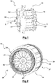
- the figures 1, 2 , and 3 show a rotating electrical machine 10 comprising a polyphase stator 11 surrounding a rotor 12 mounted on a shaft 13 of axis X.
- the stator 11 surrounds the rotor 12 with the presence of an air gap 15 between the internal periphery of the stator 11 and the external periphery rotor 12.
- the stator 11 is mounted in a housing 14 provided with a front bearing 17 and a rear bearing 18, the configuration of which is described in more detail below.
- This electric machine 10 is intended to be coupled to a gearbox 16 visible in figure 4 belonging to a traction chain of a motor vehicle.
- the machine 10 is able to operate in an alternator mode in order to supply energy in particular to the battery and to the on-board network of the vehicle, and in an engine mode, not only for starting the thermal engine of the vehicle, but also for participate in the traction of the vehicle alone or in combination with the heat engine.
- the power of the machine 10 may be between 15kW and 50kW.
- the rotor 12 comprises a body 19 in the form of a pack of sheets. Permanent magnets 20 are implanted in cavities 21 of the body 19.
- the magnets 20 may be made of rare earth or ferrite depending on the applications and the desired power of the machine 10.
- the poles of the rotor 12 may be formed by coils. .
- the machine 10 is thus devoid of a brush, which allows it to be immersed in the oil bath contained in the gearbox 16, as explained below.
- the stator 11 comprises a body 23 formed by a bundle of sheets as well as a coil 24.
- the body 23 is formed by a stack of sheets of sheets independent of each other and held in the form of a package by means of a suitable fixing system.
- Body 23 shown in detail on the figure 5 is provided with teeth 31 extending from an internal periphery of an annular yoke 32 and delimiting two by two notches 33 for mounting the coil 24 of the stator 11.
- teeth 31 extending from an internal periphery of an annular yoke 32 and delimiting two by two notches 33 for mounting the coil 24 of the stator 11.
- two successive notches 33 are separated by a tooth 31.
- the notches 33 open axially into the axial end faces and radially towards the inside of the stator body 23.
- the winding 24 comprises a set of phase windings passing through the notches 33 and forming buns 36, 37 extending projecting on either side of the stator body 23 (cf. figure 2 ).
- the phase windings are obtained here from conductive elements in the form of pins interconnected for example by welding. These windings are for example three-phase windings connected in star or delta. The phase outputs of these phase windings are intended to be connected to an electrical control module.
- the electric machine 10 is cooled by means of a cooling circuit 41 illustrated in figure 3 allowing the flow of a cooling liquid, in this case oil, inside the machine 10.
- the cooling circuit 41 comprises a pump 42 conveying the oil in an axial bore central 43 produced in the shaft 13 and towards at least two orifices 44 opening radially and arranged axially on either side of the rotor 12 to diffuse the cooling liquid inside the machine 10.
- the cooling circuit 41 operates in a closed loop, such that the oil is taken by the pump 42 from a reservoir. 45 and is recovered after circulation in the machine 10 in this reservoir 45.
- the reservoir 45 may correspond to the volume of oil contained in the gearbox 16.
- the rotor 12 comprises two flanges 48 each pressed against an axial end face of the rotor 12. These flanges 48 provide axial retention of the magnets 20 inside the cavities 21 and also serve to balance the rotor 12.
- Each flange 48 may advantageously be provided with at least one projection member 49, consisting of a blade, arranged to project by centrifugation the cooling liquid arriving on the corresponding end face towards the chumbles of the coil 36, 37.
- the machine 10 is positioned inside the volume 52 delimited by a casing 53 of the gearbox 16 containing oil 54 used for lubricating the various mechanical components of the gearbox 16 and for cooling the gearbox 16.
- the cooling liquid is sprayed onto the outer periphery of the electric machine 10 to ensure its cooling.
- the liquid 54 contained in the gearbox 16 is also used to internally cool the machine 10 via the cooling circuit 41.
- a liquid different from that contained in the gearbox could be used. for the internal cooling of the machine 10.
- the electric machine 10 is arranged in the volume 52, such that the pinion 57 carried by the shaft 13 meshes with a corresponding pinion 58 of the gearbox 16.
- the front bearing 17 and the rear bearing 18 are provided with a central opening 60 to allow the passage of the shaft 13.
- the rear bearing 18 carries a bearing 61, such as a ball or needle bearing for the rotational mounting of the shaft 13.
- the free end of the shaft 13 protruding from the housing 14 of the electric machine 10 is rotatably mounted via a bearing 62 carried by the housing 53 of the gearbox 16, as shown in figure figure 4 .
- the machine 10 comprises a single bearing 61, which facilitates the assembly of the machine 10 inside the gearbox 16 and limits the risks of hyperstatism of the assembly.
- the front bearing 17 may include a rolling support 64 disposed on a radial face.
- This bearing support 64 is formed by an annular wall projecting from a radial outer surface of the bearing 17.
- the bearing support 64 is intended to receive a bearing (not shown) of a shaft of the gearbox. speeds 16.
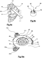
- a position sensor 67 capable of measuring the angular position of the rotor 12 is mounted around the shaft 13. This sensor 67 extends at least partially in a through-housing 68 formed in a wall of the rear bearing 18.
- the sensor 67 shown in detail on the figure 6 comprises an annular portion 71 delimiting a through hole 72 for the passage of the shaft 13, and an arm 73 providing the mechanical connection between said annular portion 71 and a cup 74 defining a housing for probes, for example of the Hall effect type.
- Cup 74 extends axially inwardly of machine 10 through housing 68.
- Housing 68 for sensor 67 has a greater circumferential dimension than cup 74 to allow rotational adjustment of sensor 67.
- a retaining plate 77 is fixed on the bearing 18 and comes into contact with a portion of the sensor 67, so that the sensor 67 is clamped between the bearing 18 and the plate 77.
- the plate 77 is arranged to provide axial locking. and a rotational locking of the sensor 67.
- the retaining plate 77 comprises in the example shown three projecting lugs 771 coming from an outer periphery of a part of annular shape extending above the portion. 71. These ears 771 are provided with holes for the passage of fasteners 772, in the occurrence of screws.
- the plate 77 may also be provided with tongues 773 on its outer periphery which are folded against an extra thickness 181 of the bearing 18 having a shape following that of the periphery of the plate 77. Such a configuration makes it possible to limit the angular displacements of the plate as much as possible. plate 77.
- the senor 67 may include an annular rim 78 projecting axially against which the retaining plate 77 rests.
- the arm 73 is then supported by one face against the bearing 18 and by an opposite face against the plate 77 via the rim 78 protruding.
- the retaining plate 77 applies to the sensor 67 a predetermined rotational locking torque sufficient to withstand the vibrations of the machine 10 and to be overcome by a torque applied by a tool 81 for adjusting the angular position of the sensor 67, such as this. is shown on the figure 9a .
- the operator can manipulate an adjustment tool 81 whose shapes 82 engage in complementary recesses 83 made in the sensor 67.
- the head 84 of the adjustment tool 81 may for example comprise cylindrical studs 82 intended to be inserted into cylindrical hollows 83 of complementary shape made on the internal periphery of the annular portion 71 of the sensor 67.
- a locking system 86 is provided to lock the position of the sensor 67 in rotation once the adjustment has been completed using the tool 81.
- the sensor 67 comprises a projecting portion 87 which is deformable, for example when hot, and is intended to fit into at least one radial notch 88 among a plurality of notches formed along an angular sector of the internal periphery of the plate 77.
- the notches 88 can be obtained by producing a serrated profile on the periphery internal of the annular part of the plate 77, the notches 88 extending between two successive teeth on the aforementioned angular sector.
- the projecting portion 87 may be deformed by hot snap-fastening along arrow F2 to fit into at least one notch 88 of the plate 77.
- the deformed configuration of the portion 87 is referenced 87 'on the figure. figure 10b .
- the system 86 has a safety function, insofar as the rupture of the mechanical connection between the sensor 67 and the plate 77 makes it possible to detect an unauthorized modification of the position of the sensor 67.
- the sensor 67 comprises a circumferential through groove 91 in which a tab 92 of the plate 77 is inserted by deformation in particular in an axial direction along the arrow F3.
- the part of the plate 77 carrying the tab 92 is superimposed axially above the groove 91.
- the deformable tab 92 extends in a recess of the plate 77 and has a shape in the form of its free end. T having a width greater than that of the groove 91 to ensure the retention of the sensor 67 after insertion of the tab 92 through the groove 91.
- the tab 92 In the initial state, that is to say not deformed, the tab 92 is located in the plane of the retaining plate 77 (cf. figure 11a ), while in the deformed state the tab 92 extends inside the groove 91 in an inclined direction, for example perpendicular to the extension plane of the plate 77, such that the edges of the T of the tab 92 form a stop against the portion of the sensor 67 defining the groove 91 (cf. figure 11b ).
Claims (11)
- Drehende elektrische Maschine, insbesondere für ein Kraftfahrzeug, umfassend:- einen Rotor (12), der um eine Achse (X) drehbar auf einer Welle (13) montiert ist,- mindestens ein Lager (18), das eine zentrale Öffnung (60) zum Durchführen der Welle (13) umfasst, wobei das Lager (18) eine durchgehende Aufnahme (68) umfasst,- mindestens einen Winkelpositionssensor (67) für den Rotor (12), wobei der Positionssensor (67) um die Welle (13) herum montiert ist,- eine Halteplatte (77) an dem Lager (18) befestigt ist und mit einem Abschnitt des Positionssensors (67) in Kontakt ist, so dass der Positionssensor (67) zwischen das Lager (18) und die Halteplatte (77) geklemmt ist,dadurch gekennzeichnet, dass die Halteplatte (77) dazu eingerichtet ist, ein vorbestimmtes Drehblockiermoment aufzubringen, das ausreicht, um den Schwingungen der drehenden elektrischen Maschine (10) standzuhalten und von einem Moment überwunden zu werden, das von einem Einstellwerkzeug (81) zum Einstellen der Winkelposition des Positionssensors (67) aufgebracht wird.
- Drehende elektrische Maschine nach Anspruch 1, dadurch gekennzeichnet, dass die Halteplatte (77) dazu eingerichtet ist, eine axiale Blockierung und eine Drehblockierung des Positionssensors (67) zu gewährleisten.
- Drehende elektrische Maschine nach Anspruch 1 oder 2, dadurch gekennzeichnet, dass der Positionssensor (67) einen, insbesondere ringförmigen, Rand (78) umfasst, wobei der Rand (78) axial vorspringt und an ihm die Halteplatte (77) in Anlage ist.
- Drehende elektrische Maschine nach einem der Ansprüche 1 bis 3, dadurch gekennzeichnet, dass der Positionssensor (67) einen ringförmigen Abschnitt (71) umfasst, der ein durchgehendes Loch (72) zum Durchführen der Welle (13) begrenzt, wobei der ringförmige Abschnitt (71) am inneren Umfang mindestens eine Vertiefung (83) umfasst, die dazu bestimmt ist, eine passende Form (82) des Einstellwerkzeugs (81) aufzunehmen.
- Drehende elektrische Maschine nach Anspruch 4, dadurch gekennzeichnet, dass der Positionssensor (67) einen Arm (73) umfasst, der eine mechanische Verbindung zwischen dem ringförmigen Abschnitt (71) und einer Wanne (74) gewährleistet, die eine Aufnahme für Messsonden, insbesondere vom Hall-Effekt-Typ, bildet.
- Drehende elektrische Maschine nach den Ansprüchen 3 und 5, dadurch gekennzeichnet, dass der Arm (73) mit einer Seite an dem Lager (18) und mit einer entgegengesetzten Seite über den vorspringenden Rand (78) an der Halteplatte (77) in Anlage ist.
- Drehende elektrische Maschine nach Anspruch 5 oder 6, dadurch gekennzeichnet, dass sich die Wanne (74) axial zum Inneren der drehenden elektrischen Maschine (10) hin erstreckt.
- Drehende elektrische Maschine nach einem der Ansprüche 5 bis 7, dadurch gekennzeichnet, dass die Sensoraufnahme (68) des Lagers (18) ein größeres umfängliches Maß als die Wanne (74) aufweist, um eine Dreheinstellung des Positionssensor (67) zu ermöglichen.
- Drehende elektrische Maschine nach einem der Ansprüche 1 bis 8, dadurch gekennzeichnet, dass sie ein Sperrsystem (86) zur Drehsperre des Positionssensors (67) umfasst.
- Drehende elektrische Maschine nach Anspruch 9, dadurch gekennzeichnet, dass der Positionssensor (67) einen verformbaren vorspringenden Abschnitt (87) umfasst, der dazu bestimmt ist, in mindestens einen radialen Ausschnitt (88) unter einer Vielzahl eingeführt zu werden, die entlang eines Winkelsektors eines Innenumfangs der Halteplatte (77) ausgebildet sind.
- Drehende elektrische Maschine nach Anspruch 9, dadurch gekennzeichnet, dass der Positionssensor (67) eine umfängliche Rille (91) umfasst, in die eine Zunge (92) der Halteplatte (77) durch Verformung, insbesondere entlang einer axialen Richtung, eingeführt werden kann.
Applications Claiming Priority (2)
| Application Number | Priority Date | Filing Date | Title |
|---|---|---|---|
| FR1654908A FR3051999A1 (fr) | 2016-05-31 | 2016-05-31 | Machine electrique tournante munie d'une plaque de maintien d'un capteur de position angulaire du rotor |
| PCT/FR2017/051363 WO2017207926A1 (fr) | 2016-05-31 | 2017-05-31 | Machine électrique tournante munie d'une plaque de maintien d'un capteur de position angulaire du rotor |
Publications (2)
| Publication Number | Publication Date |
|---|---|
| EP3465892A1 EP3465892A1 (de) | 2019-04-10 |
| EP3465892B1 true EP3465892B1 (de) | 2021-02-17 |
Family
ID=57045063
Family Applications (1)
| Application Number | Title | Priority Date | Filing Date |
|---|---|---|---|
| EP17731239.4A Active EP3465892B1 (de) | 2016-05-31 | 2017-05-31 | Elektrische drehmaschine mit halteplatte für einen sensor der winkelposition des rotors |
Country Status (5)
| Country | Link |
|---|---|
| EP (1) | EP3465892B1 (de) |
| JP (1) | JP7129915B2 (de) |
| CN (1) | CN109155578B (de) |
| FR (1) | FR3051999A1 (de) |
| WO (1) | WO2017207926A1 (de) |
Families Citing this family (5)
| Publication number | Priority date | Publication date | Assignee | Title |
|---|---|---|---|---|
| FR3075501B1 (fr) * | 2017-12-14 | 2020-03-20 | Valeo Equipements Electriques Moteur | Machine electrique tournante munie d'un dispositif de maintien d'un support de capteurs de mesure de la position angulaire du rotor |
| FR3108974B1 (fr) * | 2020-04-06 | 2022-04-01 | Valeo Equip Electr Moteur | Dispositif de mesure de position de rotor pour unité de stator de machine électrique tournante |
| WO2023287881A1 (en) * | 2021-07-14 | 2023-01-19 | Nidec Motor Corporation | Motor encoder assembly providing optimized sensor alignment |
| FR3130961B1 (fr) * | 2021-12-17 | 2023-12-22 | Valeo Equip Electr Moteur | Dispositif de mesure de position pour unité de stator de machine électrique tournante |
| CN114465065B (zh) * | 2022-01-06 | 2023-11-03 | 广东汇天航空航天科技有限公司 | 飞行器主轴滑环装置、飞行器旋翼系统及飞行器 |
Family Cites Families (16)
| Publication number | Priority date | Publication date | Assignee | Title |
|---|---|---|---|---|
| DE9315994U1 (de) * | 1993-10-20 | 1994-02-24 | Stroeter Antriebstech Gmbh | Flanschmotor mit Meßeinrichtung zur Erfassung der Umdrehung der Motorwelle |
| JP3499734B2 (ja) * | 1997-10-22 | 2004-02-23 | 株式会社ミツバ | 回転電機および電動機兼用発電機 |
| JP4103018B2 (ja) * | 1998-09-02 | 2008-06-18 | 株式会社安川電機 | サーボモータ |
| JP2000197332A (ja) * | 1998-12-28 | 2000-07-14 | Seiko Epson Corp | ステ―タコアおよびモ―タ |
| JP4071484B2 (ja) * | 2000-12-22 | 2008-04-02 | 株式会社ミツバ | モータ装置 |
| JP4617794B2 (ja) * | 2004-09-21 | 2011-01-26 | 日本電産株式会社 | モータおよびその製造方法 |
| JP2007089312A (ja) * | 2005-09-22 | 2007-04-05 | Ntn Corp | モータ回転軸の角度検出装置 |
| JP2008109834A (ja) * | 2006-09-29 | 2008-05-08 | Asmo Co Ltd | ブラシレスモータ |
| FR2935564A1 (fr) * | 2008-09-03 | 2010-03-05 | Michelin Soc Tech | Dispositif de montage d'un resolver dans une machine electrique |
| JP5606078B2 (ja) * | 2010-01-19 | 2014-10-15 | 日本電産サンキョー株式会社 | モータ |
| KR101133320B1 (ko) * | 2010-02-05 | 2012-04-04 | 삼성전기주식회사 | 엔코더 센서, 엔코더 센서를 구비한 모터 및 이 모터를 탑재한 광 디스크 구동장치 |
| CN201653383U (zh) * | 2010-04-20 | 2010-11-24 | 张占稳 | 用于扫描电机的位置探测器改进结构以及该扫描电机 |
| JP5658914B2 (ja) * | 2010-06-07 | 2015-01-28 | 株式会社不二工機 | モータ式アクチュエータ及び弁装置用アクチュエータ |
| JP5728951B2 (ja) * | 2011-01-11 | 2015-06-03 | 日本電産株式会社 | モータ |
| FR2998734B1 (fr) * | 2012-11-28 | 2016-02-05 | Faurecia Bloc Avant | Moteur electrique comprenant au moins un capteur de flux magnetique |
| CN105281497A (zh) * | 2015-10-29 | 2016-01-27 | 李宗平 | 一种内置控制系统电动机的控制结构 |
-
2016
- 2016-05-31 FR FR1654908A patent/FR3051999A1/fr active Pending
-
2017
- 2017-05-31 EP EP17731239.4A patent/EP3465892B1/de active Active
- 2017-05-31 JP JP2018562637A patent/JP7129915B2/ja active Active
- 2017-05-31 WO PCT/FR2017/051363 patent/WO2017207926A1/fr unknown
- 2017-05-31 CN CN201780026783.2A patent/CN109155578B/zh active Active
Also Published As
| Publication number | Publication date |
|---|---|
| CN109155578B (zh) | 2020-09-15 |
| JP2019517764A (ja) | 2019-06-24 |
| EP3465892A1 (de) | 2019-04-10 |
| JP7129915B2 (ja) | 2022-09-02 |
| WO2017207926A1 (fr) | 2017-12-07 |
| CN109155578A (zh) | 2019-01-04 |
| FR3051999A1 (fr) | 2017-12-01 |
Similar Documents
| Publication | Publication Date | Title |
|---|---|---|
| EP3465892B1 (de) | Elektrische drehmaschine mit halteplatte für einen sensor der winkelposition des rotors | |
| WO2017121930A1 (fr) | Machine electrique tournante à refroidissement amelioré | |
| EP3190688B1 (de) | Stator für elektrisch umlaufende maschine | |
| EP3236562B1 (de) | Elektrisch umlaufende maschine, die die elektromagnetischen störungen durch ein messelement minimiert | |
| FR2935561A1 (fr) | Flasque connecteur pour machine electrique a enroulements statoriques | |
| EP3127217B1 (de) | Elektrische maschine mit verbesserter vorrichtung zur überwachung der winkelposition des rotors und entsprechende getriebeanordnung | |
| FR3080720A1 (fr) | Machine electrique tournante munie d'un systeme de maintien d'un faisceau electrique | |
| EP3320601B1 (de) | Drehende elektromaschine mit einem zentrierelement | |
| FR3052000A1 (fr) | Machine electrique tournante munie d'un capteur de mesure de la position angulaire du rotor deporte | |
| EP3382856A1 (de) | Elektrisch umlaufende maschine mit optimierter kühlung | |
| FR3049129A1 (fr) | Machine electrique tournante muni d'un stator monte sans frettage | |
| FR3065338A1 (fr) | Machine electrique tournante munie d'un dispositif de mesure de la position angulaire du rotor a configuration amelioree | |
| EP3223400A1 (de) | Elektrisch umlaufende maschine mit drei lagern | |
| FR3075501A1 (fr) | Machine electrique tournante munie d'un dispositif de maintien d'un support de capteurs de mesure de la position angulaire du rotor | |
| EP3465888B1 (de) | Drehende elektromaschine mit wasserdichten deckeln | |
| FR3058846B1 (fr) | Machine electrique tournante comprenant un arbre de rotor et un roulement | |
| WO2017207927A1 (fr) | Machine électrique tournante munie de bouchons d'étanchéité | |
| EP3139473B1 (de) | Elektrisch umlaufende maschine, die mit verbesserten nachverfolgungsmitteln der winkelposition des rotors ausgestattet ist | |
| WO2021191515A1 (fr) | Rotor pour moteur électrique équipé de capteur de tiges | |
| FR3033457B1 (fr) | Machine electrique tournante munie de moyens de suivi ameliores de la position angulaire du rotor | |
| WO2017009547A1 (fr) | Machine électrique tournante munie d'un moyen de réglage de la position angulaire de l'arbre | |
| FR3050587A1 (fr) | Machine electrique tournante munie d'un conducteur electrique de liaison d'enroulements | |
| FR3082673A1 (fr) | Machine electrique tournante | |
| FR3088502A1 (fr) | Machine electrique tournante munie d'un peigne de guidage de sorties de phases | |
| FR3062257A1 (fr) | Machine electrique tournante equipee d'un roulement-capteur et procede de montage d'une telle machine |
Legal Events
| Date | Code | Title | Description |
|---|---|---|---|
| STAA | Information on the status of an ep patent application or granted ep patent |
Free format text: STATUS: UNKNOWN |
|
| STAA | Information on the status of an ep patent application or granted ep patent |
Free format text: STATUS: THE INTERNATIONAL PUBLICATION HAS BEEN MADE |
|
| PUAI | Public reference made under article 153(3) epc to a published international application that has entered the european phase |
Free format text: ORIGINAL CODE: 0009012 |
|
| STAA | Information on the status of an ep patent application or granted ep patent |
Free format text: STATUS: REQUEST FOR EXAMINATION WAS MADE |
|
| 17P | Request for examination filed |
Effective date: 20180731 |
|
| AK | Designated contracting states |
Kind code of ref document: A1 Designated state(s): AL AT BE BG CH CY CZ DE DK EE ES FI FR GB GR HR HU IE IS IT LI LT LU LV MC MK MT NL NO PL PT RO RS SE SI SK SM TR |
|
| AX | Request for extension of the european patent |
Extension state: BA ME |
|
| DAV | Request for validation of the european patent (deleted) | ||
| DAX | Request for extension of the european patent (deleted) | ||
| GRAP | Despatch of communication of intention to grant a patent |
Free format text: ORIGINAL CODE: EPIDOSNIGR1 |
|
| STAA | Information on the status of an ep patent application or granted ep patent |
Free format text: STATUS: GRANT OF PATENT IS INTENDED |
|
| INTG | Intention to grant announced |
Effective date: 20200911 |
|
| GRAS | Grant fee paid |
Free format text: ORIGINAL CODE: EPIDOSNIGR3 |
|
| GRAA | (expected) grant |
Free format text: ORIGINAL CODE: 0009210 |
|
| STAA | Information on the status of an ep patent application or granted ep patent |
Free format text: STATUS: THE PATENT HAS BEEN GRANTED |
|
| AK | Designated contracting states |
Kind code of ref document: B1 Designated state(s): AL AT BE BG CH CY CZ DE DK EE ES FI FR GB GR HR HU IE IS IT LI LT LU LV MC MK MT NL NO PL PT RO RS SE SI SK SM TR |
|
| REG | Reference to a national code |
Ref country code: GB Ref legal event code: FG4D Free format text: NOT ENGLISH |
|
| REG | Reference to a national code |
Ref country code: CH Ref legal event code: EP |
|
| REG | Reference to a national code |
Ref country code: DE Ref legal event code: R096 Ref document number: 602017032675 Country of ref document: DE |
|
| REG | Reference to a national code |
Ref country code: AT Ref legal event code: REF Ref document number: 1362797 Country of ref document: AT Kind code of ref document: T Effective date: 20210315 |
|
| REG | Reference to a national code |
Ref country code: IE Ref legal event code: FG4D Free format text: LANGUAGE OF EP DOCUMENT: FRENCH |
|
| REG | Reference to a national code |
Ref country code: SK Ref legal event code: T3 Ref document number: E 36829 Country of ref document: SK |
|
| REG | Reference to a national code |
Ref country code: LT Ref legal event code: MG9D |
|
| REG | Reference to a national code |
Ref country code: NL Ref legal event code: MP Effective date: 20210217 |
|
| PG25 | Lapsed in a contracting state [announced via postgrant information from national office to epo] |
Ref country code: HR Free format text: LAPSE BECAUSE OF FAILURE TO SUBMIT A TRANSLATION OF THE DESCRIPTION OR TO PAY THE FEE WITHIN THE PRESCRIBED TIME-LIMIT Effective date: 20210217 Ref country code: FI Free format text: LAPSE BECAUSE OF FAILURE TO SUBMIT A TRANSLATION OF THE DESCRIPTION OR TO PAY THE FEE WITHIN THE PRESCRIBED TIME-LIMIT Effective date: 20210217 Ref country code: GR Free format text: LAPSE BECAUSE OF FAILURE TO SUBMIT A TRANSLATION OF THE DESCRIPTION OR TO PAY THE FEE WITHIN THE PRESCRIBED TIME-LIMIT Effective date: 20210518 Ref country code: PT Free format text: LAPSE BECAUSE OF FAILURE TO SUBMIT A TRANSLATION OF THE DESCRIPTION OR TO PAY THE FEE WITHIN THE PRESCRIBED TIME-LIMIT Effective date: 20210617 Ref country code: NO Free format text: LAPSE BECAUSE OF FAILURE TO SUBMIT A TRANSLATION OF THE DESCRIPTION OR TO PAY THE FEE WITHIN THE PRESCRIBED TIME-LIMIT Effective date: 20210517 Ref country code: BG Free format text: LAPSE BECAUSE OF FAILURE TO SUBMIT A TRANSLATION OF THE DESCRIPTION OR TO PAY THE FEE WITHIN THE PRESCRIBED TIME-LIMIT Effective date: 20210517 Ref country code: LT Free format text: LAPSE BECAUSE OF FAILURE TO SUBMIT A TRANSLATION OF THE DESCRIPTION OR TO PAY THE FEE WITHIN THE PRESCRIBED TIME-LIMIT Effective date: 20210217 |
|
| REG | Reference to a national code |
Ref country code: AT Ref legal event code: MK05 Ref document number: 1362797 Country of ref document: AT Kind code of ref document: T Effective date: 20210217 |
|
| PG25 | Lapsed in a contracting state [announced via postgrant information from national office to epo] |
Ref country code: RS Free format text: LAPSE BECAUSE OF FAILURE TO SUBMIT A TRANSLATION OF THE DESCRIPTION OR TO PAY THE FEE WITHIN THE PRESCRIBED TIME-LIMIT Effective date: 20210217 Ref country code: LV Free format text: LAPSE BECAUSE OF FAILURE TO SUBMIT A TRANSLATION OF THE DESCRIPTION OR TO PAY THE FEE WITHIN THE PRESCRIBED TIME-LIMIT Effective date: 20210217 Ref country code: PL Free format text: LAPSE BECAUSE OF FAILURE TO SUBMIT A TRANSLATION OF THE DESCRIPTION OR TO PAY THE FEE WITHIN THE PRESCRIBED TIME-LIMIT Effective date: 20210217 Ref country code: NL Free format text: LAPSE BECAUSE OF FAILURE TO SUBMIT A TRANSLATION OF THE DESCRIPTION OR TO PAY THE FEE WITHIN THE PRESCRIBED TIME-LIMIT Effective date: 20210217 Ref country code: SE Free format text: LAPSE BECAUSE OF FAILURE TO SUBMIT A TRANSLATION OF THE DESCRIPTION OR TO PAY THE FEE WITHIN THE PRESCRIBED TIME-LIMIT Effective date: 20210217 |
|
| PG25 | Lapsed in a contracting state [announced via postgrant information from national office to epo] |
Ref country code: IS Free format text: LAPSE BECAUSE OF FAILURE TO SUBMIT A TRANSLATION OF THE DESCRIPTION OR TO PAY THE FEE WITHIN THE PRESCRIBED TIME-LIMIT Effective date: 20210617 |
|
| PG25 | Lapsed in a contracting state [announced via postgrant information from national office to epo] |
Ref country code: SM Free format text: LAPSE BECAUSE OF FAILURE TO SUBMIT A TRANSLATION OF THE DESCRIPTION OR TO PAY THE FEE WITHIN THE PRESCRIBED TIME-LIMIT Effective date: 20210217 Ref country code: AT Free format text: LAPSE BECAUSE OF FAILURE TO SUBMIT A TRANSLATION OF THE DESCRIPTION OR TO PAY THE FEE WITHIN THE PRESCRIBED TIME-LIMIT Effective date: 20210217 Ref country code: EE Free format text: LAPSE BECAUSE OF FAILURE TO SUBMIT A TRANSLATION OF THE DESCRIPTION OR TO PAY THE FEE WITHIN THE PRESCRIBED TIME-LIMIT Effective date: 20210217 Ref country code: CZ Free format text: LAPSE BECAUSE OF FAILURE TO SUBMIT A TRANSLATION OF THE DESCRIPTION OR TO PAY THE FEE WITHIN THE PRESCRIBED TIME-LIMIT Effective date: 20210217 |
|
| REG | Reference to a national code |
Ref country code: DE Ref legal event code: R097 Ref document number: 602017032675 Country of ref document: DE |
|
| PG25 | Lapsed in a contracting state [announced via postgrant information from national office to epo] |
Ref country code: RO Free format text: LAPSE BECAUSE OF FAILURE TO SUBMIT A TRANSLATION OF THE DESCRIPTION OR TO PAY THE FEE WITHIN THE PRESCRIBED TIME-LIMIT Effective date: 20210217 Ref country code: DK Free format text: LAPSE BECAUSE OF FAILURE TO SUBMIT A TRANSLATION OF THE DESCRIPTION OR TO PAY THE FEE WITHIN THE PRESCRIBED TIME-LIMIT Effective date: 20210217 |
|
| PLBE | No opposition filed within time limit |
Free format text: ORIGINAL CODE: 0009261 |
|
| STAA | Information on the status of an ep patent application or granted ep patent |
Free format text: STATUS: NO OPPOSITION FILED WITHIN TIME LIMIT |
|
| REG | Reference to a national code |
Ref country code: CH Ref legal event code: PL |
|
| 26N | No opposition filed |
Effective date: 20211118 |
|
| GBPC | Gb: european patent ceased through non-payment of renewal fee |
Effective date: 20210531 |
|
| PG25 | Lapsed in a contracting state [announced via postgrant information from national office to epo] |
Ref country code: AL Free format text: LAPSE BECAUSE OF FAILURE TO SUBMIT A TRANSLATION OF THE DESCRIPTION OR TO PAY THE FEE WITHIN THE PRESCRIBED TIME-LIMIT Effective date: 20210217 Ref country code: CH Free format text: LAPSE BECAUSE OF NON-PAYMENT OF DUE FEES Effective date: 20210531 Ref country code: LU Free format text: LAPSE BECAUSE OF NON-PAYMENT OF DUE FEES Effective date: 20210531 Ref country code: MC Free format text: LAPSE BECAUSE OF FAILURE TO SUBMIT A TRANSLATION OF THE DESCRIPTION OR TO PAY THE FEE WITHIN THE PRESCRIBED TIME-LIMIT Effective date: 20210217 Ref country code: LI Free format text: LAPSE BECAUSE OF NON-PAYMENT OF DUE FEES Effective date: 20210531 Ref country code: ES Free format text: LAPSE BECAUSE OF FAILURE TO SUBMIT A TRANSLATION OF THE DESCRIPTION OR TO PAY THE FEE WITHIN THE PRESCRIBED TIME-LIMIT Effective date: 20210217 |
|
| REG | Reference to a national code |
Ref country code: BE Ref legal event code: MM Effective date: 20210531 |
|
| PG25 | Lapsed in a contracting state [announced via postgrant information from national office to epo] |
Ref country code: SI Free format text: LAPSE BECAUSE OF FAILURE TO SUBMIT A TRANSLATION OF THE DESCRIPTION OR TO PAY THE FEE WITHIN THE PRESCRIBED TIME-LIMIT Effective date: 20210217 |
|
| PG25 | Lapsed in a contracting state [announced via postgrant information from national office to epo] |
Ref country code: IT Free format text: LAPSE BECAUSE OF FAILURE TO SUBMIT A TRANSLATION OF THE DESCRIPTION OR TO PAY THE FEE WITHIN THE PRESCRIBED TIME-LIMIT Effective date: 20210217 Ref country code: IE Free format text: LAPSE BECAUSE OF NON-PAYMENT OF DUE FEES Effective date: 20210531 Ref country code: GB Free format text: LAPSE BECAUSE OF NON-PAYMENT OF DUE FEES Effective date: 20210531 |
|
| PG25 | Lapsed in a contracting state [announced via postgrant information from national office to epo] |
Ref country code: IS Free format text: LAPSE BECAUSE OF FAILURE TO SUBMIT A TRANSLATION OF THE DESCRIPTION OR TO PAY THE FEE WITHIN THE PRESCRIBED TIME-LIMIT Effective date: 20210617 |
|
| PG25 | Lapsed in a contracting state [announced via postgrant information from national office to epo] |
Ref country code: BE Free format text: LAPSE BECAUSE OF NON-PAYMENT OF DUE FEES Effective date: 20210531 |
|
| PG25 | Lapsed in a contracting state [announced via postgrant information from national office to epo] |
Ref country code: CY Free format text: LAPSE BECAUSE OF FAILURE TO SUBMIT A TRANSLATION OF THE DESCRIPTION OR TO PAY THE FEE WITHIN THE PRESCRIBED TIME-LIMIT Effective date: 20210217 |
|
| P01 | Opt-out of the competence of the unified patent court (upc) registered |
Effective date: 20230528 |
|
| PG25 | Lapsed in a contracting state [announced via postgrant information from national office to epo] |
Ref country code: HU Free format text: LAPSE BECAUSE OF FAILURE TO SUBMIT A TRANSLATION OF THE DESCRIPTION OR TO PAY THE FEE WITHIN THE PRESCRIBED TIME-LIMIT; INVALID AB INITIO Effective date: 20170531 |
|
| PGFP | Annual fee paid to national office [announced via postgrant information from national office to epo] |
Ref country code: FR Payment date: 20230523 Year of fee payment: 7 Ref country code: DE Payment date: 20230510 Year of fee payment: 7 |
|
| PGFP | Annual fee paid to national office [announced via postgrant information from national office to epo] |
Ref country code: SK Payment date: 20230418 Year of fee payment: 7 |
|
| PG25 | Lapsed in a contracting state [announced via postgrant information from national office to epo] |
Ref country code: MK Free format text: LAPSE BECAUSE OF FAILURE TO SUBMIT A TRANSLATION OF THE DESCRIPTION OR TO PAY THE FEE WITHIN THE PRESCRIBED TIME-LIMIT Effective date: 20210217 |