EP3465178B1 - Vorrichtung zur identifizierung von physikalischen parametern von stabförmigen artikeln der tabakverarbeitenden industrie - Google Patents
Vorrichtung zur identifizierung von physikalischen parametern von stabförmigen artikeln der tabakverarbeitenden industrie Download PDFInfo
- Publication number
- EP3465178B1 EP3465178B1 EP17735624.3A EP17735624A EP3465178B1 EP 3465178 B1 EP3465178 B1 EP 3465178B1 EP 17735624 A EP17735624 A EP 17735624A EP 3465178 B1 EP3465178 B1 EP 3465178B1
- Authority
- EP
- European Patent Office
- Prior art keywords
- rod
- articles
- radiation
- path conveyor
- conveyor
- Prior art date
- Legal status (The legal status is an assumption and is not a legal conclusion. Google has not performed a legal analysis and makes no representation as to the accuracy of the status listed.)
- Revoked
Links
Images


Classifications
-
- A—HUMAN NECESSITIES
- A24—TOBACCO; CIGARS; CIGARETTES; SIMULATED SMOKING DEVICES; SMOKERS' REQUISITES
- A24C—MACHINES FOR MAKING CIGARS OR CIGARETTES
- A24C5/00—Making cigarettes; Making tipping materials for, or attaching filters or mouthpieces to, cigars or cigarettes
- A24C5/32—Separating, ordering, counting or examining cigarettes; Regulating the feeding of tobacco according to rod or cigarette condition
- A24C5/34—Examining cigarettes or the rod, e.g. for regulating the feeding of tobacco; Removing defective cigarettes
- A24C5/3412—Examining cigarettes or the rod, e.g. for regulating the feeding of tobacco; Removing defective cigarettes by means of light, radiation or electrostatic fields
-
- G—PHYSICS
- G01—MEASURING; TESTING
- G01N—INVESTIGATING OR ANALYSING MATERIALS BY DETERMINING THEIR CHEMICAL OR PHYSICAL PROPERTIES
- G01N23/00—Investigating or analysing materials by the use of wave or particle radiation, e.g. X-rays or neutrons, not covered by groups G01N3/00 – G01N17/00, G01N21/00 or G01N22/00
- G01N23/02—Investigating or analysing materials by the use of wave or particle radiation, e.g. X-rays or neutrons, not covered by groups G01N3/00 – G01N17/00, G01N21/00 or G01N22/00 by transmitting the radiation through the material
- G01N23/06—Investigating or analysing materials by the use of wave or particle radiation, e.g. X-rays or neutrons, not covered by groups G01N3/00 – G01N17/00, G01N21/00 or G01N22/00 by transmitting the radiation through the material and measuring the absorption
- G01N23/083—Investigating or analysing materials by the use of wave or particle radiation, e.g. X-rays or neutrons, not covered by groups G01N3/00 – G01N17/00, G01N21/00 or G01N22/00 by transmitting the radiation through the material and measuring the absorption the radiation being X-rays
-
- A—HUMAN NECESSITIES
- A24—TOBACCO; CIGARS; CIGARETTES; SIMULATED SMOKING DEVICES; SMOKERS' REQUISITES
- A24D—CIGARS; CIGARETTES; TOBACCO SMOKE FILTERS; MOUTHPIECES FOR CIGARS OR CIGARETTES; MANUFACTURE OF TOBACCO SMOKE FILTERS OR MOUTHPIECES
- A24D3/00—Tobacco smoke filters, e.g. filter-tips, filtering inserts; Filters specially adapted for simulated smoking devices; Mouthpieces for cigars or cigarettes
- A24D3/02—Manufacture of tobacco smoke filters
- A24D3/0295—Process control means
-
- G—PHYSICS
- G01—MEASURING; TESTING
- G01N—INVESTIGATING OR ANALYSING MATERIALS BY DETERMINING THEIR CHEMICAL OR PHYSICAL PROPERTIES
- G01N2223/00—Investigating materials by wave or particle radiation
- G01N2223/60—Specific applications or type of materials
- G01N2223/621—Specific applications or type of materials tobacco
-
- G—PHYSICS
- G01—MEASURING; TESTING
- G01N—INVESTIGATING OR ANALYSING MATERIALS BY DETERMINING THEIR CHEMICAL OR PHYSICAL PROPERTIES
- G01N2223/00—Investigating materials by wave or particle radiation
- G01N2223/60—Specific applications or type of materials
- G01N2223/643—Specific applications or type of materials object on conveyor
Definitions
- the subject of the invention is an apparatus for identification of physical parameters of rod-like articles of the tobacco industry.
- Tobacco industry products including cigarettes, cigarillos, cigars, filter rods made of a single filtering material, multi-segment rods comprising multiple segments, and all types of semi-finished products processed at particular stages of production may be referred to by a common name - rod-like articles.
- Some rod-like articles such as filter rods and filter cigarettes, may contain capsules with an aromatic substance.
- Quality control may be performed by random selection or may be applied to all articles produced. Quality control concerns both the appearance and the dimensions of the articles, and in the case of articles containing capsules, the level of filling of the capsules is significant.
- the purpose of this invention is to find an optimal solution combining the process efficiency and the correctness of quality control.
- the physical parameters which require identification are the length of segments and the position of segments relative to one another along the axis of the rods as well as the position of the capsules in the segments along the axis of the rods and transversely to the axis of the rods.
- the purpose of measurement is to detect any defects of the rods, for example the spaces among the segments which should touch one other. Another defect is a non-central position of the capsule or an improper position of the capsule along the axis.
- the physical parameter which should be detected may be for example an undesired material concentration which, in a finished cigarette with a filter tip, may result in a too big resistance to airflow through the filter tip.
- the physical parameter which should be detected may be for example an undesired material concentration which, in a finished cigarette with a filter tip, may result in a too big resistance to airflow through the filter tip.
- the application DE102014209721A1 discloses a method of identifying the parameters of rod-like articles using x-rays wherein the rod-like articles are placed in a rotating clamp.
- the documents EP0790006B1 and EP2769632A1 disclose a method and an apparatus wherein the parameters of an article, among others the material density, are determined by x-raying the article in different directions. Additional analysis systems for rod-like articles are also known from US 5,762,075 and WO 2015/039851 .
- the use of multilayer and multipath conveyor systems during manufacture of rod-like articles is disclosed in EP 2 995 207 .
- the object of the invention is an apparatus for identification of physical parameters of rod-like articles of the tobacco industry provided with a multi-path conveyor of rod-like articles; a radiation source arranged for emitting radiation towards the paths of the multi-path conveyor; a radiation sensor arranged so that the it receives the radiation from the radiation source, after the radiation penetrated through the multi-path conveyor of rod-like articles; wherein the radiation source and the radiation sensor are situated on opposite sides of the transferring plane.
- the apparatus according to the invention is characterised in that the multi-part conveyor of the rod-like articles is a single-layer multi-path conveyor, the radiation source is a single point type radiation source the radiation sensor is positioned transversely to the paths of the conveyor, whereas the radiation sensor is arranged so that it produces a signal representing attenuation of the radiation penetrating through the rod-like articles on the paths of the multi-path conveyor, situated between the radiation source and the radiation sensor.
- the transverse positioning of the sensor enables including multiple paths in the scope of measurement, which enables increasing the number of simultaneously scanned rod-like articles with the scanning speed remaining unchanged.
- the apparatus may optionally be characterised in that the radiation sensor is a linear sensor or a matrix.
- the radiation sensor is a linear sensor or a matrix.
- the introduction of a linear sensor or a matrix enables further increasing of the possibilities of determining the physical parameters using a more detailed graphical analysis of the obtained signal representing attenuation of the radiation penetrating through the articles.
- the apparatus may optionally be characterised in that the multi-path conveyor of rod-like articles is arranged so that it enables transferring the groups of rod-like articles in a single plane, parallel to one another. Placing the rod-like articles in a single plane, parallel to one another, makes it easier to produce a signal being easier to process.
- the apparatus may optionally be characterised in that the multi-path conveyor of rod-like articles is arranged so that all rod-like articles in a group are aligned to one another.
- the alignment of the rod-like articles makes it easier to produce a signal being easier to process.
- the apparatus may optionally be further characterised in that the radiation sensor is situated beneath the carying surface of the multi-path conveyor.
- the apparatus may optionally be further characterised in that the radiation sensor is situated between the multi-path conveyor and a first hopper.
- the apparatus may optionally be further characterised by being provided with a rotating unit for simultaneous rotation of rod-like articles in a group at the time of measurement of the parameters of rod-like articles.
- the apparatus may optionally be further characterised in that the rotating unit is integrated with the first hopper.
- the apparatus may optionally be characterised in that the source of radiation is a source of electromagnetic radiation of a frequency in the range between 10 12 and 10 19 Hz.
- the use of electromagnetic radiation in this range enables measuring the parameters of rod-like articles containing materials with a high degree of radiation absorption in other frequency ranges.
- the apparatus may optionally be characterised in that the source of radiation is arranged so that the intensity of emitted radiation is adjustable to the speed of the multi-path conveyor.
- the apparatus may optionally be characterised in that the radiation sensor is arranged so that the exposure time of the radiation sensor depends on the speed of the multi-path conveyor.
- the adjustment of the radiation intensity and the exposure time relative to the speed of the multi-path conveyor enables obtaining the maximum measuring speed while maintaining the measuring accuracy; a greater intensity enables shortening the required exposure time, which results in an increased speed of the multi-path conveyor.
- the apparatus may optionally be characterised by being further provided with a processing station which is adapted to collect the signal delivered from the radiation sensor and produce on its basis an image representing attenuation of the radiation along the length of at least one rod-like article.
- the processing station enables obtaining an image of susceptibility generated on the basis of a series of linear or matrix measurements.
- the physical parameters of the rod-like articles may be shown in the graphical form so that the entire group of rod-like articles can be seen in a single image in all analysed paths at full length of the rod-like articles.
- An advantage of the apparatus as in the invention is a high certainty of correctness of the results for various materials.
- Fig. 1 shows a fragment of a production line comprising a first hopper 1 for rod-like articles 2, a multi-path conveyor 3 of rod-like articles 2 and a measuring unit 4.
- the first hopper 1 which is a supplying device for the conveyor 3, is fed through a channel 5 (shown in the drawing as not filled with the articles), the upper part of the first hopper 1 constitutes a chamber 6, whereas the bottom part of the first conveyor 1 has the form of multiple channels 8 whose width is slightly greater than the diameter of the rod-like articles 2.
- the channels 8 are closed from the bottom by a wall 9 on which the rod-like articles 2 are situated.
- a pushing mechanism 10 which makes a reciprocating motion and pushes the group G of rod like articles 2 out of the channels 8, whereas the group G comprises respectively one lowest situated article 2 of each channel 8.
- the rod-like articles 2 in the group G are aligned after being pushed out of the channels 8, i.e. their ends are arranged in line.
- a pushing element 11 of the pushing mechanism 10 may have the form of multiple rod-shaped pushers 12 in a number corresponding to the number of the rod-like articles 2 in the group G.
- the multi-path conveyor 3 has the form of a belt conveyor which comprises a multi-groove belt 13 which is wound round two rollers 14 and 15, whereas the roller 15 is driven by means of a not shown motor.
- the spaces between the grooves 16 are adapted to the spaces between the channels 8.
- the grooves 16, which constitute the carrying surface of the multi-path conveyor 3, may for example have the form of the letter V or the form of the letter U.
- the multi-path conveyor 3 may also be a chain conveyor.
- the grooves 16 determine the paths of movement for the rod-like articles 2, whereas in Fig.
- the path of movement P is not limited to the space directly above the carrying surface of the multi-path conveyor 3, but it extends in the direction before and behind the multi-path conveyor 3 considering the direction of movement of the conveyor 3.
- the paths of movement P of rod-like articles are parallel to one another and lie in the transferring plane A which may be determined on the surface of the multi-groove belt 13.
- a radiation source 17 is situated, while beneath the surface of the multi-groove belt 13 a radiation sensor 18 is situated. It is possible to make a reverse configuration where the radiation source 17 is situated beneath the transferring plane A, and the radiation sensor 18 above it.
- the radiation source 17 emits the radiation R which penetrates through the paths P in the transferring plane A and reaches the radiation sensor 18.
- the radiation sensor 18 may have the form of a strip or a matrix, whereas the matrix may comprise a plurality of individual sensors.
- the radiation sensor 18 may be arranged to receive the electromagnetic radiation of a frequency in the range between 10 12 and 10 19 Hz. In the embodiment the radiation sensor 18 was shown as a strip arranged to receive the radiation R.
- the radiation source 17 and the radiation sensor 18 determine a plane B.
- the plane B as well as the radiation sensor 18 in a top view is situated perpendicular to the direction of movement T of the rod-like articles 2 on the multi-groove belt 13, thus perpendicular to the axis of the articles 2 and to the paths of movement P.
- the radiation source 17 may be arranged to generate a flat beam referred to as sheet beam, whereas such beam is directed at the radiation sensor 18. It is possible to use such radiation source 17 whose radiation intensity or exposure time will be adjustable to the speed of movement of the rod-like articles.
- Behind the multi-path conveyor 3 there is situated a conveyor 19 onto which the rod-like articles 2 are supplied from the multi-path conveyor 3.
- the conveyor 19 conveys the rod-like articles 2 transversely to the axis of these articles and transversely to the direction of movement T of the rod-like articles 2 on the multi-path conveyor 3.
- the rod-like articles 2 are fed through the channel 5 in the form of a mass flow to the chamber 6 of the first hopper 1, and then they pass through the channels 8 of the bottom part of the first hopper 1.
- the pushing mechanism 10 making reciprocating motions the rod-like articles 2 situated lowest in the channels 8 are pushed out as a group G from the channels 8 and are fed to the grooves 16 on the multi-groove belt 13.
- the rod-like articles 2 move on multiple paths P along the grooves 16 of the conveyor 3.
- the group G of rod-like articles 2 is conveyed on the belt 13 of the multi-path conveyor 3 in the direction T and passes through the plane B; a measurement is made when the article group G passes through this plane.
- the radiation R emitted by the radiation source 17 penetrates through the transferred articles 2.
- the radiation R while penetrating through the rod-like articles 2 is partially absorbed by the material of the articles 2.
- the radiation R from the radiation source 17 penetrates to a different extent through different materials used in the rod-like articles 2 due to different radiation hardness of such materials.
- the radiation sensor 18 receives the radiation R for successive positions of the rod-like articles 2, i.e. the representations of successive cross-sections of the rod-like article 2 are created in the form of successive lines which represent the attenuation of radiation in successive cross-sections of the rod-like articles 2. In other words, the sensor receives information about the properties of the material in successive cross-sections of the rod-like articles 2.
- the signals S which contain information about the successive cross-sections are sent to the processing station 20 for successive cross-sections along the length of the rod-like articles.
- the signals S may be converted to a single line of a created image.
- the processing station 20, having received successive signals S, makes a compilation of such signals in order to obtain a two-dimensional image of the rod-like articles 2 in the group G.
- the processing station 20 may prepare an image of the entire group, i.e. all articles in the group G, or separate images of individual articles of the group G, whereas it is possible for a receiver in the form of both a strip and a matrix.
- the rod-like articles 2 are transferred from the multi-path conveyor 3 to a receiving device 19. After an analysis of the prepared images any defective rod-like articles 2 may be rejected from the production.
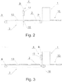
- Figs. 2 and 3 show example locations of the measuring unit 4 comprising the radiation source 17 and the radiation sensor 18.
- the rod-like articles 2 are transferred above the radiation sensor 18 with the travel speed of the multi-groove belt 13.
- the radiation sensor 18 may be situated at a certain distance from the first hopper 1 (as in Fig. 2 ) or right next to the first hopper 1 (as in Fig. 3 ). If the measuring unit 4 is located right next to the first hopper 1 the transfer of the article group G above the radiation sensor 18 may be accomplished simultaneously with pushing out the article group G by the pushing mechanism 10.
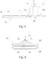
- the multi-path conveyor 3 has been moved away from the first hopper 1.
- a first rotating unit 21 for simultaneous rotation of the rod-like articles 2 pushed out of the first hopper 1 in the form of the group G of rod-like articles 2.
- the radiation sensor 18 receives the radiation emitted from the radiation source 17, and the images of rod-like articles are generated based on which the position of elements placed in the article may be determined in three dimensions.
- the elements placed in the rod-like articles 2 comprise capsules with aromatic substances and various inserts made of metal or plastic.
- the rotating unit 21 may be arranged to rotate the rod-like articles 2 after they have been pushed out by the pushing unit 10 or when the rod-like articles 2 are being pushed out by the pushing unit 10, whereas the rod-shaped pushers 12 of the pushing unit 10 may have the possibility of rotation around the axis of rotation of the rod-like articles 2.
- the possibility of rotation of the rod-shaped pushers 12 reduces the friction between the rod-like articles 2 and the rod-shaped pushers 12 during the rotation of the rod-like articles 2 by the rotating unit 21.
- Fig. 5 shows an embodiment of the rotating unit 21 in the form of two belts 22 and 23 which are put in motion during the rotation of the rod-like articles 2 so that the sections of the belts coming into contact with the rod-like articles 2 move in opposite directions TL and TR.
- Fig. 6 shows an example of the rod-like article 2 in the form of a multi-segment filter rod situated along the path of movement P on the multi-groove belt 13.
- the multi-segment filter rod contains components in the form of four segments 2A, 2B, 2C and 2D, whereas a capsule 2E is positioned in the segment 2C (the rod was shown as transparent without any wrapping material).
- Fig. 7 shows a two-dimensional image of a multi-segment rod generated after that rod has been x-rayed, whereas the image may be generated on the basis of a measurement made with the aid of the method described above using the radiation sensor in the form of a strip as well as a two-dimensional matrix.
- Fig. 8 shows an image of a multi-segment rod subjected to further processing.
- Example dimensions such as segment lengths z1, z2, z4, full rod length z6 and capsule position defined by the dimension z3 or z5 which may be used in the quality analysis have been marked.
Landscapes
- Health & Medical Sciences (AREA)
- Toxicology (AREA)
- General Health & Medical Sciences (AREA)
- Biochemistry (AREA)
- Chemical & Material Sciences (AREA)
- Analytical Chemistry (AREA)
- Life Sciences & Earth Sciences (AREA)
- Physics & Mathematics (AREA)
- General Physics & Mathematics (AREA)
- Immunology (AREA)
- Pathology (AREA)
- Manufacturing Of Cigar And Cigarette Tobacco (AREA)
- Analysing Materials By The Use Of Radiation (AREA)
Claims (12)
- Die Vorrichtung zur Identifizierung physikalischer Parameter von stäbchenförmigen Gegenständen der Tabakindustrie mit
einen Mehrwegförderer (3) aus stabförmigen Gegenständen (2), der mit stabförmigen Gegenständen von einer Zufuhrvorrichtung gespeist wird;
eine Strahlungsquelle (17), die angeordnet ist, um Strahlung (R) in Richtung der Wege (P) des Mehrwegförderers (3) zu emittieren;
einen Strahlungssensor (18), der so angeordnet ist, dass er die Strahlung (R) von der Strahlungsquelle (17) empfängt, nachdem die Strahlung (R) durch den Mehrwegförderer (3) von stabförmigen Gegenständen (2) eingedrungen ist;
worin
befinden sich die Strahlungsquelle (17) und der Strahlungssensor (18) auf gegenüberliegenden Seiten einer Übertragungsebene (A);
ist dadurch gekennzeichnet, dass
Mehrwegförderer (3) der stabförmigen Gegenstände (2) ein einschichtiger Mehrwegförderer ist
und
die Strahlungsquelle (17) eine Einzelpunktstrahlungsquelle ist,
der Strahlungssensor (18) ist quer zu den Wegen (P) des Mehrwegförderers (3) positioniert,
wohingegen
ist der Strahlungssensor (18) so angeordnet, dass er ein Signal (S) erzeugt, das die Dämpfung der Strahlung (R) darstellt, die durch die stabförmigen Gegenstände (2) auf den Wegen (P) des Mehrwegförderers (3) zwischen der Strahlungsquelle (17) und dem Strahlungssensor (18) eindringt. - Die Vorrichtung nach Anspruch 1 ist dadurch gekennzeichnet, dass der Strahlungssensor (18) ein linearer Sensor oder eine Matrix ist.
- Die Vorrichtung nach Anspruch 1 oder 2 ist dadurch gekennzeichnet, dass der Mehrwegförderer (3) von stabförmigen Gegenständen (2) so angeordnet ist, dass er das Übertragen der Gruppen (G) von stabförmigen Gegenständen (2) in einer einzigen Ebene, parallel zueinander, ermöglicht.
- Die Vorrichtung nach Anspruch 3 ist dadurch gekennzeichnet, dass der Mehrwegförderer (3) von stabförmigen Gegenständen (2) so angeordnet ist, dass alle stabförmigen Gegenstände (2) in einer Gruppe (G) zueinander ausgerichtet sind.
- Die Vorrichtung nach einem der Ansprüche 1 bis 4 ist dadurch gekennzeichnet, dass der Strahlungssensor (18) unter der Tragfläche des Mehrwegförderers (3) angeordnet ist.
- Die Vorrichtung nach einem der Ansprüche 1 bis 4 ist dadurch gekennzeichnet, dass der Strahlungssensor (18) zwischen dem Mehrwegförderer (3) und einem ersten Trichter (1) angeordnet ist.
- Die Vorrichtung wie in einem der vorhergehenden Ansprüche ist dadurch gekennzeichnet, dass sie mit einer rotierenden Einheit (21) zum gleichzeitigen Drehen der stabförmigen Gegenstände (2) in einer Gruppe (G) zum Zeitpunkt der Messung von Parametern der stabförmigen Gegenstände (2) gekennzeichnet ist.
- Die Vorrichtung wie in einem der vorhergehenden Ansprüche ist dadurch gekennzeichnet, dass die rotierende Einheit (21) in den ersten Trichter (1) integriert ist.
- Die Vorrichtung wie in einem der vorhergehenden Ansprüche 1 bis 8 ist dadurch gekennzeichnet, dass die Strahlungsquelle (17) eine Quelle elektromagnetischer Strahlung mit einer Frequenz im Bereich zwischen 1012 und 1019 Hz ist.
- Die Vorrichtung nach einem der vorhergehenden Ansprüche 1 bis 9 ist dadurch gekennzeichnet, dass die Strahlungsquelle (17) so angeordnet ist, dass die Intensität der emittierten Strahlung (R) auf die Geschwindigkeit des Mehrwegförderers (3) einstellbar ist.
- Die Vorrichtung nach einem der vorhergehenden Ansprüche 1 bis 10 ist dadurch gekennzeichnet, dass der Strahlungssensor (18) so angeordnet ist, dass die Belichtungszeit des Strahlungssensors (18) von der Geschwindigkeit des Mehrwegförderers (3) abhängt.
- Die Vorrichtung nach einem der vorhergehenden Ansprüche 1 bis 11 ist gekennzeichnet dadurch, dass sie ferner mit einer Verarbeitungsstation (20) versehen ist, die dazu ausgelegt ist, das vom Strahlungssensor (18) gelieferte Signal (S) zu sammeln und auf der Basis des Signals (S) ein Bild, das die Abschwächung der Strahlung (R) entlang der Länge mindestens eines stabförmigen Gegenstands (2) darstellt.
Applications Claiming Priority (2)
| Application Number | Priority Date | Filing Date | Title |
|---|---|---|---|
| PL417391A PL234550B1 (pl) | 2016-06-03 | 2016-06-03 | Urządzenie do identyfikacji parametrów fizycznych artykułów prętopodobnych przemysłu tytoniowego |
| PCT/IB2017/052908 WO2017208104A1 (en) | 2016-06-03 | 2017-05-17 | Apparatus for identification of physical parameters of rod-like articles of the tobacco industry |
Publications (2)
| Publication Number | Publication Date |
|---|---|
| EP3465178A1 EP3465178A1 (de) | 2019-04-10 |
| EP3465178B1 true EP3465178B1 (de) | 2020-04-08 |
Family
ID=60473198
Family Applications (1)
| Application Number | Title | Priority Date | Filing Date |
|---|---|---|---|
| EP17735624.3A Revoked EP3465178B1 (de) | 2016-06-03 | 2017-05-17 | Vorrichtung zur identifizierung von physikalischen parametern von stabförmigen artikeln der tabakverarbeitenden industrie |
Country Status (8)
| Country | Link |
|---|---|
| US (1) | US20190383756A1 (de) |
| EP (1) | EP3465178B1 (de) |
| JP (1) | JP2019522789A (de) |
| KR (1) | KR20190016024A (de) |
| CN (1) | CN109219744A (de) |
| BR (1) | BR112018074798A2 (de) |
| PL (1) | PL234550B1 (de) |
| RU (1) | RU2018141945A (de) |
Families Citing this family (2)
| Publication number | Priority date | Publication date | Assignee | Title |
|---|---|---|---|---|
| US11058143B2 (en) * | 2017-10-19 | 2021-07-13 | R.J. Reynolds Tobacco Company | Smoking-related article inspection systems and associated methods |
| CN109985822B (zh) * | 2019-05-05 | 2023-06-30 | 成都瑞拓科技有限责任公司 | 滤棒进料装置、进料输送装置及爆珠卷烟/滤棒检测仪 |
Citations (14)
| Publication number | Priority date | Publication date | Assignee | Title |
|---|---|---|---|---|
| US2932391A (en) | 1951-08-02 | 1960-04-12 | American Mach & Foundry | Cigarette rod density measuring apparatus |
| US4209955A (en) | 1978-01-06 | 1980-07-01 | G.D. Societa Per Azioni | Device for feeding and checking layers of cigarettes in cigarette packaging machines |
| WO1995031908A1 (en) | 1994-05-19 | 1995-11-30 | Molins Plc | Cigarette manufacture |
| DE19518640A1 (de) | 1995-05-20 | 1996-11-21 | Hauni Maschinenbau Ag | Dichtemeßeinrichtung für Strangmaschinen der tabakverarbeitenden Industrie |
| US5762075A (en) | 1996-02-15 | 1998-06-09 | Hauni Maschinenbau Ag | Method of and apparatus for ascertaining the density of a stream of fibrous material |
| CN1320867C (zh) | 2003-09-12 | 2007-06-13 | 北京清大科技股份有限公司 | 条烟缺包在线检测装置及其检测方法 |
| US20080063148A1 (en) | 2004-06-11 | 2008-03-13 | Ishida Co., Ltd. | X-Ray Inspection Apparatus |
| EP2163886A1 (de) | 2007-03-12 | 2010-03-17 | Ishida Co., Ltd. | Röntgen-inspektionsvorrichtung und produktionssystem |
| EP2261645A1 (de) | 2009-06-08 | 2010-12-15 | Ishida Co., Ltd. | Röntgeninspektionsgerät |
| EP2293049A2 (de) | 2009-07-16 | 2011-03-09 | Yokogawa Electric Corporation | Strahlungsprüfvorrichtung |
| EP2352014A1 (de) | 2008-11-11 | 2011-08-03 | Hamamatsu Photonics K.K. | Strahlungserkennungsvorrichtung, strahlungsbilderfassungssystem, strahlungsinspektionssystem und strahlungserkennungsverfahren |
| WO2012080686A1 (en) | 2010-12-15 | 2012-06-21 | Molins Plc | Apparatus for imaging features of a rod |
| DE102011053971A1 (de) | 2011-09-27 | 2013-03-28 | Wipotec Wiege- Und Positioniersysteme Gmbh | Verfahren und Vorrichtung zum Erfassen der Struktur von bewegten Stückgütern, insbesondere zur Erfassung von Störpartikeln in flüssigen oder pastösen Produkten |
| DE102014209721A1 (de) | 2014-05-22 | 2015-11-26 | Hauni Maschinenbau Ag | Verfahren zur Bestimmung einer Eigenschaft eines stabförmigen Artikels der Tabak verarbeitenden Industrie mittels Röntgenstrahlung, und Probenhalter |
Family Cites Families (10)
| Publication number | Priority date | Publication date | Assignee | Title |
|---|---|---|---|---|
| US4327665A (en) * | 1979-07-26 | 1982-05-04 | Clemens Arrasmith | Method and apparatus for coating composition on can seams |
| CN1301960A (zh) * | 1999-12-29 | 2001-07-04 | 李广寅 | 集装箱中卷烟探测成像装置 |
| US6583423B2 (en) * | 2001-11-16 | 2003-06-24 | Ion Beam Applications, S.A. | Article irradiation system with multiple beam paths |
| US6976384B2 (en) * | 2002-10-31 | 2005-12-20 | Nanostream, Inc. | Parallel detection chromatography systems |
| US7873201B2 (en) * | 2004-11-10 | 2011-01-18 | L-3 Communications Security and Detection Systems Inc. | Reconstruction of x-ray images into basis function components using multiple-energy sources |
| GB0706089D0 (en) * | 2007-03-29 | 2007-10-31 | Durham Scient Crystals Ltd | X-ray imaging of materials |
| GB2451076A (en) * | 2007-07-16 | 2009-01-21 | Illinois Tool Works | Inspection apparatus and method using penetrating radiation |
| GB201316691D0 (en) * | 2013-09-20 | 2013-11-06 | British American Tobacco Co | Inspection of rod shaped articles of the tobacco industry |
| JP6613228B2 (ja) * | 2013-11-04 | 2019-11-27 | フィリップ・モーリス・プロダクツ・ソシエテ・アノニム | ロッド状の物品を運搬するためのシステムおよび方法、ならびにロッド状の物品をコンベヤーバンド内に保持するための配列および方法 |
| EP2995207A1 (de) * | 2014-09-12 | 2016-03-16 | International Tobacco Machinery Poland Sp. z o.o. | Transportsystem |
-
2016
- 2016-06-03 PL PL417391A patent/PL234550B1/pl unknown
-
2017
- 2017-05-17 BR BR112018074798-0A patent/BR112018074798A2/pt not_active Application Discontinuation
- 2017-05-17 RU RU2018141945A patent/RU2018141945A/ru not_active Application Discontinuation
- 2017-05-17 JP JP2018563161A patent/JP2019522789A/ja active Pending
- 2017-05-17 KR KR1020187035202A patent/KR20190016024A/ko unknown
- 2017-05-17 EP EP17735624.3A patent/EP3465178B1/de not_active Revoked
- 2017-05-17 CN CN201780034360.5A patent/CN109219744A/zh active Pending
- 2017-05-17 US US16/303,603 patent/US20190383756A1/en not_active Abandoned
Patent Citations (15)
| Publication number | Priority date | Publication date | Assignee | Title |
|---|---|---|---|---|
| US2932391A (en) | 1951-08-02 | 1960-04-12 | American Mach & Foundry | Cigarette rod density measuring apparatus |
| US4209955A (en) | 1978-01-06 | 1980-07-01 | G.D. Societa Per Azioni | Device for feeding and checking layers of cigarettes in cigarette packaging machines |
| WO1995031908A1 (en) | 1994-05-19 | 1995-11-30 | Molins Plc | Cigarette manufacture |
| DE19518640A1 (de) | 1995-05-20 | 1996-11-21 | Hauni Maschinenbau Ag | Dichtemeßeinrichtung für Strangmaschinen der tabakverarbeitenden Industrie |
| US5762075A (en) | 1996-02-15 | 1998-06-09 | Hauni Maschinenbau Ag | Method of and apparatus for ascertaining the density of a stream of fibrous material |
| CN1320867C (zh) | 2003-09-12 | 2007-06-13 | 北京清大科技股份有限公司 | 条烟缺包在线检测装置及其检测方法 |
| US20080063148A1 (en) | 2004-06-11 | 2008-03-13 | Ishida Co., Ltd. | X-Ray Inspection Apparatus |
| US20080298547A1 (en) | 2004-06-11 | 2008-12-04 | Ishida Co., Ltd. | X-ray inspection apparatus |
| EP2163886A1 (de) | 2007-03-12 | 2010-03-17 | Ishida Co., Ltd. | Röntgen-inspektionsvorrichtung und produktionssystem |
| EP2352014A1 (de) | 2008-11-11 | 2011-08-03 | Hamamatsu Photonics K.K. | Strahlungserkennungsvorrichtung, strahlungsbilderfassungssystem, strahlungsinspektionssystem und strahlungserkennungsverfahren |
| EP2261645A1 (de) | 2009-06-08 | 2010-12-15 | Ishida Co., Ltd. | Röntgeninspektionsgerät |
| EP2293049A2 (de) | 2009-07-16 | 2011-03-09 | Yokogawa Electric Corporation | Strahlungsprüfvorrichtung |
| WO2012080686A1 (en) | 2010-12-15 | 2012-06-21 | Molins Plc | Apparatus for imaging features of a rod |
| DE102011053971A1 (de) | 2011-09-27 | 2013-03-28 | Wipotec Wiege- Und Positioniersysteme Gmbh | Verfahren und Vorrichtung zum Erfassen der Struktur von bewegten Stückgütern, insbesondere zur Erfassung von Störpartikeln in flüssigen oder pastösen Produkten |
| DE102014209721A1 (de) | 2014-05-22 | 2015-11-26 | Hauni Maschinenbau Ag | Verfahren zur Bestimmung einer Eigenschaft eines stabförmigen Artikels der Tabak verarbeitenden Industrie mittels Röntgenstrahlung, und Probenhalter |
Also Published As
| Publication number | Publication date |
|---|---|
| US20190383756A1 (en) | 2019-12-19 |
| BR112018074798A2 (pt) | 2019-03-12 |
| KR20190016024A (ko) | 2019-02-15 |
| JP2019522789A (ja) | 2019-08-15 |
| EP3465178A1 (de) | 2019-04-10 |
| PL234550B1 (pl) | 2020-03-31 |
| CN109219744A (zh) | 2019-01-15 |
| RU2018141945A (ru) | 2020-07-10 |
| PL417391A1 (pl) | 2017-12-04 |
Similar Documents
| Publication | Publication Date | Title |
|---|---|---|
| RU2649380C2 (ru) | Способ и устройство для детектирования повернутых сегментов в многосегментном стержне, перемещаемом в машине, используемой в табачном производстве | |
| EP3465179B1 (de) | Vorrichtung zur identifizierung von physikalischen parametern von stabförmigen artikeln der tabakverarbeitenden industrie | |
| EP3465178B1 (de) | Vorrichtung zur identifizierung von physikalischen parametern von stabförmigen artikeln der tabakverarbeitenden industrie | |
| US11105750B2 (en) | Method and system for the automatic measuring of physical and dimensional parameters of multi-segment articles | |
| PL362073A1 (pl) | Sposób pomiaru co najmniej jednego fizycznego, zwłaszcza geometrycznego, parametru transportowanychprzewodem transportowym sztabkowych wyrobów przemysłu tytoniowego, zwłaszcza sztabek filtrowych, i urządzenie do transportu sztabek filtrowych do magazynu filtrów | |
| WO2017208103A1 (en) | Apparatus for identification of physical parameters of rod-like articles of the tobacco industry | |
| JP6546991B2 (ja) | タバコ産業用の機械で移送される転回セグメントの検知方法及び検知装置、並びに該装置を備えるマルチセグメント・ロッドの製造機械 | |
| JP3715524B2 (ja) | X線異物検出装置 | |
| WO2017208104A1 (en) | Apparatus for identification of physical parameters of rod-like articles of the tobacco industry | |
| EP3468392B1 (de) | Vorrichtung zur bestimmung der position eines einsatzes in stabförmigen artikeln der tabakverarbeitenden industrie | |
| CN113316397B (zh) | 烟草加工业的棒形产品的质量检查 | |
| JP2004347603A (ja) | 特に煙草加工産業のロッド状対象物の直径を測定する装置 | |
| EP3872482B1 (de) | Vorrichtung und verfahren zur durchführung eines computertomografiescans eines objekts mit länglicher form, insbesondere von holzbrettern | |
| JP2007212366A (ja) | 被検部厚の検査方法及び装置 | |
| CN104172467B (zh) | 用于光学评价烟草加工业的棒状物件的测量系统 | |
| WO2019175769A1 (en) | An inspection unit and method for quality control of disposable cartridges for electronic cigarettes | |
| RU2808967C2 (ru) | Устройство подачи для подачи сегмента табачной промышленности | |
| WO2017212358A1 (en) | Apparatus for determination of the position of an insert in rod-like articles of the tobacco industry | |
| US11470874B2 (en) | Feeding apparatus for feeding a tobacco industry segment | |
| EP3852557B1 (de) | Gerät zur förderung und prüfung eines halbzeugs der tabakverarbeitenden industrie | |
| KR101947373B1 (ko) | 엑스레이 흡수 특성에 의한 성분 분석 시스템 및 그에 의한 성분 분석 방법 | |
| CN115135177A (zh) | 香烟工业的棒形产品的检查方法和设备 |
Legal Events
| Date | Code | Title | Description |
|---|---|---|---|
| STAA | Information on the status of an ep patent application or granted ep patent |
Free format text: STATUS: UNKNOWN |
|
| STAA | Information on the status of an ep patent application or granted ep patent |
Free format text: STATUS: THE INTERNATIONAL PUBLICATION HAS BEEN MADE |
|
| PUAI | Public reference made under article 153(3) epc to a published international application that has entered the european phase |
Free format text: ORIGINAL CODE: 0009012 |
|
| STAA | Information on the status of an ep patent application or granted ep patent |
Free format text: STATUS: REQUEST FOR EXAMINATION WAS MADE |
|
| 17P | Request for examination filed |
Effective date: 20190102 |
|
| AK | Designated contracting states |
Kind code of ref document: A1 Designated state(s): AL AT BE BG CH CY CZ DE DK EE ES FI FR GB GR HR HU IE IS IT LI LT LU LV MC MK MT NL NO PL PT RO RS SE SI SK SM TR |
|
| AX | Request for extension of the european patent |
Extension state: BA ME |
|
| DAV | Request for validation of the european patent (deleted) | ||
| DAX | Request for extension of the european patent (deleted) | ||
| GRAP | Despatch of communication of intention to grant a patent |
Free format text: ORIGINAL CODE: EPIDOSNIGR1 |
|
| STAA | Information on the status of an ep patent application or granted ep patent |
Free format text: STATUS: GRANT OF PATENT IS INTENDED |
|
| INTG | Intention to grant announced |
Effective date: 20200129 |
|
| GRAS | Grant fee paid |
Free format text: ORIGINAL CODE: EPIDOSNIGR3 |
|
| GRAA | (expected) grant |
Free format text: ORIGINAL CODE: 0009210 |
|
| STAA | Information on the status of an ep patent application or granted ep patent |
Free format text: STATUS: THE PATENT HAS BEEN GRANTED |
|
| AK | Designated contracting states |
Kind code of ref document: B1 Designated state(s): AL AT BE BG CH CY CZ DE DK EE ES FI FR GB GR HR HU IE IS IT LI LT LU LV MC MK MT NL NO PL PT RO RS SE SI SK SM TR |
|
| REG | Reference to a national code |
Ref country code: CH Ref legal event code: EP Ref country code: AT Ref legal event code: REF Ref document number: 1255064 Country of ref document: AT Kind code of ref document: T Effective date: 20200415 |
|
| REG | Reference to a national code |
Ref country code: DE Ref legal event code: R096 Ref document number: 602017014492 Country of ref document: DE |
|
| REG | Reference to a national code |
Ref country code: IE Ref legal event code: FG4D |
|
| REG | Reference to a national code |
Ref country code: NL Ref legal event code: MP Effective date: 20200408 |
|
| REG | Reference to a national code |
Ref country code: LT Ref legal event code: MG4D |
|
| PG25 | Lapsed in a contracting state [announced via postgrant information from national office to epo] |
Ref country code: PT Free format text: LAPSE BECAUSE OF FAILURE TO SUBMIT A TRANSLATION OF THE DESCRIPTION OR TO PAY THE FEE WITHIN THE PRESCRIBED TIME-LIMIT Effective date: 20200817 Ref country code: NL Free format text: LAPSE BECAUSE OF FAILURE TO SUBMIT A TRANSLATION OF THE DESCRIPTION OR TO PAY THE FEE WITHIN THE PRESCRIBED TIME-LIMIT Effective date: 20200408 Ref country code: LT Free format text: LAPSE BECAUSE OF FAILURE TO SUBMIT A TRANSLATION OF THE DESCRIPTION OR TO PAY THE FEE WITHIN THE PRESCRIBED TIME-LIMIT Effective date: 20200408 Ref country code: GR Free format text: LAPSE BECAUSE OF FAILURE TO SUBMIT A TRANSLATION OF THE DESCRIPTION OR TO PAY THE FEE WITHIN THE PRESCRIBED TIME-LIMIT Effective date: 20200709 Ref country code: FI Free format text: LAPSE BECAUSE OF FAILURE TO SUBMIT A TRANSLATION OF THE DESCRIPTION OR TO PAY THE FEE WITHIN THE PRESCRIBED TIME-LIMIT Effective date: 20200408 Ref country code: IS Free format text: LAPSE BECAUSE OF FAILURE TO SUBMIT A TRANSLATION OF THE DESCRIPTION OR TO PAY THE FEE WITHIN THE PRESCRIBED TIME-LIMIT Effective date: 20200808 Ref country code: NO Free format text: LAPSE BECAUSE OF FAILURE TO SUBMIT A TRANSLATION OF THE DESCRIPTION OR TO PAY THE FEE WITHIN THE PRESCRIBED TIME-LIMIT Effective date: 20200708 Ref country code: SE Free format text: LAPSE BECAUSE OF FAILURE TO SUBMIT A TRANSLATION OF THE DESCRIPTION OR TO PAY THE FEE WITHIN THE PRESCRIBED TIME-LIMIT Effective date: 20200408 |
|
| REG | Reference to a national code |
Ref country code: AT Ref legal event code: MK05 Ref document number: 1255064 Country of ref document: AT Kind code of ref document: T Effective date: 20200408 |
|
| PG25 | Lapsed in a contracting state [announced via postgrant information from national office to epo] |
Ref country code: BG Free format text: LAPSE BECAUSE OF FAILURE TO SUBMIT A TRANSLATION OF THE DESCRIPTION OR TO PAY THE FEE WITHIN THE PRESCRIBED TIME-LIMIT Effective date: 20200708 Ref country code: HR Free format text: LAPSE BECAUSE OF FAILURE TO SUBMIT A TRANSLATION OF THE DESCRIPTION OR TO PAY THE FEE WITHIN THE PRESCRIBED TIME-LIMIT Effective date: 20200408 Ref country code: RS Free format text: LAPSE BECAUSE OF FAILURE TO SUBMIT A TRANSLATION OF THE DESCRIPTION OR TO PAY THE FEE WITHIN THE PRESCRIBED TIME-LIMIT Effective date: 20200408 Ref country code: LV Free format text: LAPSE BECAUSE OF FAILURE TO SUBMIT A TRANSLATION OF THE DESCRIPTION OR TO PAY THE FEE WITHIN THE PRESCRIBED TIME-LIMIT Effective date: 20200408 |
|
| REG | Reference to a national code |
Ref country code: DE Ref legal event code: R119 Ref document number: 602017014492 Country of ref document: DE |
|
| PG25 | Lapsed in a contracting state [announced via postgrant information from national office to epo] |
Ref country code: AL Free format text: LAPSE BECAUSE OF FAILURE TO SUBMIT A TRANSLATION OF THE DESCRIPTION OR TO PAY THE FEE WITHIN THE PRESCRIBED TIME-LIMIT Effective date: 20200408 |
|
| PG25 | Lapsed in a contracting state [announced via postgrant information from national office to epo] |
Ref country code: LI Free format text: LAPSE BECAUSE OF NON-PAYMENT OF DUE FEES Effective date: 20200531 Ref country code: DK Free format text: LAPSE BECAUSE OF FAILURE TO SUBMIT A TRANSLATION OF THE DESCRIPTION OR TO PAY THE FEE WITHIN THE PRESCRIBED TIME-LIMIT Effective date: 20200408 Ref country code: AT Free format text: LAPSE BECAUSE OF FAILURE TO SUBMIT A TRANSLATION OF THE DESCRIPTION OR TO PAY THE FEE WITHIN THE PRESCRIBED TIME-LIMIT Effective date: 20200408 Ref country code: SM Free format text: LAPSE BECAUSE OF FAILURE TO SUBMIT A TRANSLATION OF THE DESCRIPTION OR TO PAY THE FEE WITHIN THE PRESCRIBED TIME-LIMIT Effective date: 20200408 Ref country code: EE Free format text: LAPSE BECAUSE OF FAILURE TO SUBMIT A TRANSLATION OF THE DESCRIPTION OR TO PAY THE FEE WITHIN THE PRESCRIBED TIME-LIMIT Effective date: 20200408 Ref country code: ES Free format text: LAPSE BECAUSE OF FAILURE TO SUBMIT A TRANSLATION OF THE DESCRIPTION OR TO PAY THE FEE WITHIN THE PRESCRIBED TIME-LIMIT Effective date: 20200408 Ref country code: RO Free format text: LAPSE BECAUSE OF FAILURE TO SUBMIT A TRANSLATION OF THE DESCRIPTION OR TO PAY THE FEE WITHIN THE PRESCRIBED TIME-LIMIT Effective date: 20200408 Ref country code: CH Free format text: LAPSE BECAUSE OF NON-PAYMENT OF DUE FEES Effective date: 20200531 Ref country code: CZ Free format text: LAPSE BECAUSE OF FAILURE TO SUBMIT A TRANSLATION OF THE DESCRIPTION OR TO PAY THE FEE WITHIN THE PRESCRIBED TIME-LIMIT Effective date: 20200408 Ref country code: IT Free format text: LAPSE BECAUSE OF FAILURE TO SUBMIT A TRANSLATION OF THE DESCRIPTION OR TO PAY THE FEE WITHIN THE PRESCRIBED TIME-LIMIT Effective date: 20200408 Ref country code: MC Free format text: LAPSE BECAUSE OF FAILURE TO SUBMIT A TRANSLATION OF THE DESCRIPTION OR TO PAY THE FEE WITHIN THE PRESCRIBED TIME-LIMIT Effective date: 20200408 |
|
| PLBI | Opposition filed |
Free format text: ORIGINAL CODE: 0009260 |
|
| PLAX | Notice of opposition and request to file observation + time limit sent |
Free format text: ORIGINAL CODE: EPIDOSNOBS2 |
|
| PG25 | Lapsed in a contracting state [announced via postgrant information from national office to epo] |
Ref country code: PL Free format text: LAPSE BECAUSE OF FAILURE TO SUBMIT A TRANSLATION OF THE DESCRIPTION OR TO PAY THE FEE WITHIN THE PRESCRIBED TIME-LIMIT Effective date: 20200408 Ref country code: SK Free format text: LAPSE BECAUSE OF FAILURE TO SUBMIT A TRANSLATION OF THE DESCRIPTION OR TO PAY THE FEE WITHIN THE PRESCRIBED TIME-LIMIT Effective date: 20200408 |
|
| 26 | Opposition filed |
Opponent name: G.D S.P.A. Effective date: 20210108 |
|
| REG | Reference to a national code |
Ref country code: BE Ref legal event code: MM Effective date: 20200531 |
|
| PG25 | Lapsed in a contracting state [announced via postgrant information from national office to epo] |
Ref country code: LU Free format text: LAPSE BECAUSE OF NON-PAYMENT OF DUE FEES Effective date: 20200517 |
|
| PG25 | Lapsed in a contracting state [announced via postgrant information from national office to epo] |
Ref country code: FR Free format text: LAPSE BECAUSE OF NON-PAYMENT OF DUE FEES Effective date: 20200608 Ref country code: IE Free format text: LAPSE BECAUSE OF NON-PAYMENT OF DUE FEES Effective date: 20200517 |
|
| PG25 | Lapsed in a contracting state [announced via postgrant information from national office to epo] |
Ref country code: BE Free format text: LAPSE BECAUSE OF NON-PAYMENT OF DUE FEES Effective date: 20200531 Ref country code: DE Free format text: LAPSE BECAUSE OF NON-PAYMENT OF DUE FEES Effective date: 20201201 Ref country code: SI Free format text: LAPSE BECAUSE OF FAILURE TO SUBMIT A TRANSLATION OF THE DESCRIPTION OR TO PAY THE FEE WITHIN THE PRESCRIBED TIME-LIMIT Effective date: 20200408 |
|
| RDAF | Communication despatched that patent is revoked |
Free format text: ORIGINAL CODE: EPIDOSNREV1 |
|
| RDAG | Patent revoked |
Free format text: ORIGINAL CODE: 0009271 |
|
| STAA | Information on the status of an ep patent application or granted ep patent |
Free format text: STATUS: PATENT REVOKED |
|
| GBPC | Gb: european patent ceased through non-payment of renewal fee |
Effective date: 20210517 |
|
| REG | Reference to a national code |
Ref country code: CH Ref legal event code: PL |
|
| REG | Reference to a national code |
Ref country code: FI Ref legal event code: MGE |
|
| 27W | Patent revoked |
Effective date: 20211009 |
|
| PG25 | Lapsed in a contracting state [announced via postgrant information from national office to epo] |
Ref country code: GB Free format text: LAPSE BECAUSE OF NON-PAYMENT OF DUE FEES Effective date: 20210517 |
|
| PG25 | Lapsed in a contracting state [announced via postgrant information from national office to epo] |
Ref country code: TR Free format text: LAPSE BECAUSE OF FAILURE TO SUBMIT A TRANSLATION OF THE DESCRIPTION OR TO PAY THE FEE WITHIN THE PRESCRIBED TIME-LIMIT Effective date: 20200408 Ref country code: MT Free format text: LAPSE BECAUSE OF FAILURE TO SUBMIT A TRANSLATION OF THE DESCRIPTION OR TO PAY THE FEE WITHIN THE PRESCRIBED TIME-LIMIT Effective date: 20200408 Ref country code: CY Free format text: LAPSE BECAUSE OF FAILURE TO SUBMIT A TRANSLATION OF THE DESCRIPTION OR TO PAY THE FEE WITHIN THE PRESCRIBED TIME-LIMIT Effective date: 20200408 |
|
| PG25 | Lapsed in a contracting state [announced via postgrant information from national office to epo] |
Ref country code: MK Free format text: LAPSE BECAUSE OF FAILURE TO SUBMIT A TRANSLATION OF THE DESCRIPTION OR TO PAY THE FEE WITHIN THE PRESCRIBED TIME-LIMIT Effective date: 20200408 |