EP3464935B1 - Schwungradsystem - Google Patents
Schwungradsystem Download PDFInfo
- Publication number
- EP3464935B1 EP3464935B1 EP17733058.6A EP17733058A EP3464935B1 EP 3464935 B1 EP3464935 B1 EP 3464935B1 EP 17733058 A EP17733058 A EP 17733058A EP 3464935 B1 EP3464935 B1 EP 3464935B1
- Authority
- EP
- European Patent Office
- Prior art keywords
- flywheel
- casing wall
- casing
- rotor
- bumper
- Prior art date
- Legal status (The legal status is an assumption and is not a legal conclusion. Google has not performed a legal analysis and makes no representation as to the accuracy of the status listed.)
- Active
Links
Images




Classifications
-
- F—MECHANICAL ENGINEERING; LIGHTING; HEATING; WEAPONS; BLASTING
- F16—ENGINEERING ELEMENTS AND UNITS; GENERAL MEASURES FOR PRODUCING AND MAINTAINING EFFECTIVE FUNCTIONING OF MACHINES OR INSTALLATIONS; THERMAL INSULATION IN GENERAL
- F16F—SPRINGS; SHOCK-ABSORBERS; MEANS FOR DAMPING VIBRATION
- F16F15/00—Suppression of vibrations in systems; Means or arrangements for avoiding or reducing out-of-balance forces, e.g. due to motion
- F16F15/30—Flywheels
- F16F15/315—Flywheels characterised by their supporting arrangement, e.g. mountings, cages, securing inertia member to shaft
-
- F—MECHANICAL ENGINEERING; LIGHTING; HEATING; WEAPONS; BLASTING
- F16—ENGINEERING ELEMENTS AND UNITS; GENERAL MEASURES FOR PRODUCING AND MAINTAINING EFFECTIVE FUNCTIONING OF MACHINES OR INSTALLATIONS; THERMAL INSULATION IN GENERAL
- F16F—SPRINGS; SHOCK-ABSORBERS; MEANS FOR DAMPING VIBRATION
- F16F2230/00—Purpose; Design features
- F16F2230/10—Enclosure elements, e.g. for protection
-
- F—MECHANICAL ENGINEERING; LIGHTING; HEATING; WEAPONS; BLASTING
- F16—ENGINEERING ELEMENTS AND UNITS; GENERAL MEASURES FOR PRODUCING AND MAINTAINING EFFECTIVE FUNCTIONING OF MACHINES OR INSTALLATIONS; THERMAL INSULATION IN GENERAL
- F16F—SPRINGS; SHOCK-ABSORBERS; MEANS FOR DAMPING VIBRATION
- F16F2230/00—Purpose; Design features
- F16F2230/24—Detecting or preventing malfunction, e.g. fail safe
Definitions
- a larger sized flywheel system may comprise: a ring-shaped flywheel rotor, arranged on a rotation axis; and a substantially cylindrical casing, enveloping the flywheel rotor at least in a radial direction to contain the flywheel in case of a calamity.
- the casing is herein intended to restrict or confine the flywheel rotor in case of an emergency, such as failure of the rotation axis, a bearing and/or parts and components assembled with the flywheel rotor.
- such a casing comprises a circular wall intended to retain the flywheel rotor within the confines defined thereby.
- the flywheel rotor may stop to rotate on its own, and start to roll over the casing wall.
- the flywheel rotor may be free to move in axial and radial direction when one or more of these parts or components fail.
- flywheel rotors having for example or preferably, though not exclusively: an outer radius in radial direction of at least 0,85 meter, preferably at least 1 meter, and more preferably at least 1,30 meter; a thickness in axial direction of at least 0,20 or 30 meter, preferably at least 0,45 meter, and more preferably at least 0,60 meter; and a weight of at least 2,5 tons, preferably at least 4 tons and more preferably at least 5 tons.
- these dimensions and parameters are merely exemplary of the enormous type of flywheel rotor, to which the present disclosure may relate.
- US-2004/025625 discloses a casing having an inner wall surrounding a flywheel, with a perfectly cylindrical liner and energy absorbing restraint ribs between inside of the casing's inner wall. Although some damping might be expected from the liner and energy absorbing restraint ribs, these measures are ineffective to combat the rotational upswing of the rotor in case of a calamity, where the rotor breaks free. Also, reference is made to DE-2050108 , which discloses an air discharge and associated air flow guide plate, defining a deviation from a perfectly cylindrical shape (circular in cross section), but wherein the discharge and flow plate do not contribute at all to combating the effects of a calamity.
- DE-2049629 discloses a flywheel arranged upright to rotate around a horizontal axis, without a casing, where brakes are arranged under the flywheel to reduce rotational speed in case the flywheel comes loose from its axis.
- the flywheel system exhibits the feature that the casing, enveloping the flywheel rotor at least in a radial direction, comprises at least one inward protruding bumper defining a variation from the circular shape in cross section (the cylindrical shape) of the casing wall surrounding the flywheel rotor.
- the casing enveloping the flywheel rotor at least in a radial direction
- the casing comprises at least one inward protruding bumper defining a variation from the circular shape in cross section (the cylindrical shape) of the casing wall surrounding the flywheel rotor.
- a flywheel system may exhibit the feature that the casing wall comprises at least one inward protruding bumper, preferably at least two bumpers, and more preferably at least three bumpers.
- a bumper can be considered a specific type of deviation from a circular casing wall, which may suffice to prevent a flywheel rotor turned loose from causing catastrophic effects on the system as a whole.
- a configuration of three bumpers defining three stop or buffer points for the flywheel rotor to intentionally bump against, provides a very effective enclosure for the flywheel rotor; there is no part of the casing wall, where the flywheel rotor can pass between the bumpers in the form of protrusions, stops or buffers, if the diameter of the flywheel rotor is larger than the direct circumferential distance between neighbouring bumpers.
- the flywheel system also exhibits a feature that the inward protruding bumpers are uniformly distributed over the casing wall, in particular over the inner circumference thereof. Consequently, uniform distribution of impact forces over the circumference of the casing and the casing wall may be achieved.
- the at least one bumper defines a discontinuity in the tangential direction of the casing wall, deviating from a change in tangential direction of a circular shape.
- the at least one inward protruding bumper protrudes inward towards the flywheel rotor relative to adjoining portions of the casing wall.
- the casing wall exhibits an approximately circular curvature in cross section (the wall is cylindrical) with a radius, which is at least slightly larger than a radius of the flywheel rotor. This allows the flywheel rotor to roll over the casing inner wall over a short distance, before being nudged towards the centre by a bumper defined by a deviation from the circular shape of the casing inner wall.
- the flywheel system may exhibit additionally or alternatively the feature that the casing comprises reinforcement of the casing wall.
- a mere non-circular shape of the casing wall will contribute to a large extent to being able to maintain control over the flywheel rotor, even in case of an emergency, but the inner wall can be embodied relatively light when reinforced at appropriate locations around the circumference thereof.
- the reinforcement may comprise a backing at the at least one inward protruding bumper.
- the most effective and efficient reinforcement may be achieved in this manner, as the bumper formed by protrusions, stops, buffers or otherwise are designed to be hit by the flywheel rotor on the loose, and can consequently be most effectively reinforced using the backing, where at other locations such a backing may be omitted or provided in a less sturdy embodiment.
- a flywheel system may exhibit the feature of a brake, which is configured to, when activated, act on at least the flywheel rotor to slow down the flywheel rotor in case of emergency.
- a brake may contribute reducing the rotational speed of the flywheel rotor, after having come loose, but will only function thanks to wobble motion suppression achieved by the non-circular shape or nature of the casing wall in general and preferably axially extending protrusions, stops or buffers.
- a flywheel system may exhibit the feature of a drive and/or a power generator connected to the flywheel rotor.
- a flywheel system may exhibit the feature that the casing wall comprises either a ring shaped or cylindrical wall or a disc shaped base, which is clamped with a degree of play in a concentric configuration with the fly wheel, to absorb impact energy when the fly wheel impacts on the casing wall.
- This is considered an invention uin its own right, even having embodiments without at least one inward protruding bumper relative to the otherwise (except for the bumpers) potentially perfectly cylindrical or circular (in cross section) casing wall.
- the flywheel system according to the present disclosure exhibits the feature that the casing wall is itself circular (i.e. cylindrical) and comprises at least one bumper defining a deviation from the circular shape of the casing wall.
- a flywheel system may exhibit the feature that the bumper comprises at least one straight plate arranged at a circle section relative to the circular shape of the casing wall, alongside an enveloping circular or cylindrical shape circumscribing the flywheel rotor.
- a flywheel system may exhibit the feature that the casing wall comprises at least one front plate, defining a deviation relative to the circular shape of the casing wall and an impact absorbing bumper.
- the front plate may be made of a softer material than that of the fly wheel and/or has a lower melting temperature than that of the fly wheel.
- the front plate may be coated with a friction reducing coating.
- a flywheel system may exhibit the feature that the casing wall comprises at least one bumper, comprising an assembly of plates.
- the assembly may comprise at least two of: a backing plate connected to or integral with the casing wall; a brass front plate; a glass fibre layer; and a base plate.
- Figure 1 shows a schematic perspective representation of a three protrusion based flywheel system 1, having a casing 2, comprising a base 4 and a casing wall 5, and a disk or ring shaped flywheel rotor 3.
- the flywheel rotor is big; it generates enormous forces and unleashes tremendous powers, when it should break free from a bearing or from the rotation axis 7, connecting the flywheel rotor 3 to an energy storing drive or energy withdrawing generator, referred to as drive/generator 6.
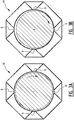
- Figures 2A and 2B most closely resembles the embodiment of figure 1 , in terms of the number of protrusions.
- three bumpers 8 defining the protrusions are provided in a manner evenly or uniformly distributed around the flywheel rotor 3. As long as the flywheel rotor is in the state of figure 2A , all is well.
- the bumpers 8 define protrusions and more generically a deviation from a circular inner surface of the casing wall 5 in the sense of the present disclosure. At each impact of flywheel 3 on such a bumper 8, the flywheel is nudged towards the middle of the casing wall and is centred as a consequence.
- the bumpers 8 extend in an axial direction of the rotation axis 7 of the system 1.
- Figures 1A and 1B are essentially the same as the configuration according to figures 2A and 2B , except that in figures 1A and 1B the system 9 comprises two bumpers 8 defining protrusions. Again, the bumpers 8 are uniformly distributed, although another distribution may well be contemplated, also relative to the configurations of figures 2A, 2B , 3A, and 3B. Figures 3A and 3B are also essentially the same except for the presence in that system 10 of four bumpers 8.
- Figure 7 exhibits a slightly different embodiment than figures 1A and 1B in an exaggerated representation.
- the embodiment distinguishes in that the protrusion is formed at a transition area or transition point 13, where two circle shapes 14, 15 meet, from which the inner surface of casing wall 5 is formed.
- the representation is exaggerated in that the rotor could spin inside one of these circles or pass along an 8-shaped trajectory, but the point of the embodiment is the shape at the transitional point, where the circular shapes 14, 15 meet and define a discontinuous transition in tangential directions T1 and T2.
- Figure 8 shows yet another embodiment with respect to the protrusion defined therein.
- an essentially triangular swivel block 16 is arranged at hinge 17 on inner surface of casing wall 5.
- a leg 19 prevents the swivel block 16 from extending too far towards the flywheel rotor 3.
- a spring 18 or another deflection motion absorbing element is provided radially behind the swivel block 16, and pushes swivel block 16 inward towards the flywheel rotor 3.
- the flywheel rotor 3 is on the loose, and rolls over the inner surface of the casing wall 5, swivel block 16 is pressed out against a reactions force from the spring 18, which spring force is responsible for nudging the flywheel 3 back to the centre of the casing.
- the spring absorbs energy through deflection of the swivel block 16, contributing to a quicker speed reduction.
- Each bumper 8 in figures 1A, 1B , 2A, 2B , 3A, and 3B is provided with oblique backing members 11, enclosed in a frame 12. Thereby specifically the bumpers may be reinforced to withstand the forces unleashed thereon when the flywheel rotor breaks free from its bearings, or from rotation axis 7 or the like.
- FIG. 4 shows further features related to a brake 20.
- Brake 20 is arranged near the centre of the flywheel rotor for two reasons:
- the brake may schematically comprise a disk to be clamped with force F onto a top surface of the flywheel disk 3, after that flywheel 3 has started to spin out of control, as indicated with double arrow A, to toll over inner surface of casing wall 5.
- brake elements (not shown) may be projected from the axis 22, around which the flywheel rotor 3 revolves, or from the inner surface of casing wall 5, or the like.
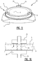
- Figures 9 and 10 show a manner in which casing wall 5 or a base 4 can be clamped with a limited degree of play, to absorb energy in case of a collision of the flywheel 3 there against.
- Uprights or anchors 24 form structural components, which are anchored to a ground or basis (not shown).
- the uprights or anchors 24 extend along or through the casing wall 5 or base 4.
- the casing wall 5 has the form of a ring, arranged on base 4.
- base 4 may be anchored to the ground, a floor or the basis (not shown).
- the uprights or anchors 24 may then be positioned in or at bevelled extremities of base 4, shown in figures 1 and 9 .
- the uprights or anchors 24 extend through casing wall 5 or base 4, through a hole 26 in casing wall 5 or base 4, which is dimensioned to be larger than the diameter of the uprights 24. This way, the ring shaped casing wall 5 or base 4 is able to be displaced over a limited distance from the original arrangement thereof, in which original placement the casing wall 5 or base 4 is concentric with fly wheel 3.
- Clamping blocks 25 are arranged under and above the casing wall 5 or base 4, and exert a clamping force F on the ring shaped casing wall 5 or base 4.
- the clamping blocks 25 thus dampen this displacement of the ring shaped casing wall 5 or base 4, whereby more quickly impact energy is absorbed.
- Lower clamping blocks 25 may be formed by an upper surface of base 4 in an embodiment having the ring shaped wall 5. Upper clamping blocks 25 may be connected to any element or component, or even attached or integral with the uprights, in order to generate a desired or required clamping and damping force F on the casing wall 5 or base 4.
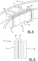
- FIGS 11 and 12 show yet another embodiment of a bumper 8, defining a deformation of the casing wall 5 relative to a perfectly circular shape thereof.
- the bumper 8 in this embodiment comprises a backing 28, forming part of or rigidly connected to the casing wall 5.
- the backing 28 defines an accommodation for an assembly of a brass or copper front plate 31, an intermediate glass fibre layer 30 for isolation and a base plate 29.
- the feature of a brass front plate allow the material of the front plate to absorb some impact energy through deformation thereof, since brass is a relatively soft metal.
- All of the elements 28 - 31 are straight plates and consequently the front surface of the brass plate in a top view defines a section of the circular shape of the casing wall 5 and a protrusion into the interior of this circular shape.
- the bumpers 8 allow sufficient room for the fly wheel 3 to rotate in a normal operational state. When the fly wheel brakes loose, the bumpers 8 define controlled points of impact into which the why wheel 3 bumps to lose energy and lose speed.
- the front plate 31 can be made of cast iron, in which case the intermediate glass fibre layer 30 for isolation and a base plate 29 may - in some embodiments - be omitted, depending on the actually selected material of the front plate 31.
- Alternative material than copper or brass may also prove to be suitable.
- the objectives for choosing copper, brass and/or cast iron relate to the material having a lower melting temperature and/or being softer than the fly wheel 3, so that upon impact the fly wheel doesn't rip into the front plate 31.
- the front plate in any embodiment having or not intermediate glass fibre layer 30 for isolation and base plate 29, may also be provided with a friction lowering coating from plastic, such as teflon, nylon, UHMWPE, and the like, or any other suitable material, to promote that the fly wheel 3 skids off bumper 8 at impact there against, in view of friction reducing properties of such a coating on the front plate.
- plastic such as teflon, nylon, UHMWPE, and the like, or any other suitable material
- figures 5 and 6 show damping in terms of rotor displacement in the direction of arrow A in figure 4 , for respective initial rotational impact speeds of 0,5 m/s and 2,8 m/s.
- a damping of radial displacement of the flywheel rotor 3 can be achieved in a matter of seconds, which is highly surprising in view of the dimensions of the enormous flywheel rotor, as mentioned above, and the very substantial rotation speeds the flywheel rotor 3.
Landscapes
- Engineering & Computer Science (AREA)
- General Engineering & Computer Science (AREA)
- Physics & Mathematics (AREA)
- Acoustics & Sound (AREA)
- Aviation & Aerospace Engineering (AREA)
- Mechanical Engineering (AREA)
- Connection Of Motors, Electrical Generators, Mechanical Devices, And The Like (AREA)
- Vibration Dampers (AREA)
- Motor Power Transmission Devices (AREA)
- Steering Controls (AREA)
Claims (15)
- Schwungradsystem (1), umfassend:- einen ringförmigen Schwungradrotor (3), welcher auf einer Drehachse (7) angeordnet ist; und- ein im Wesentlichen zylindrisches Gehäuse (2), welches den Schwungradrotor (3) zumindest in einer radialen Richtung umhüllt, um das Schwungrad (3) im Fall eines Unglücks zu enthalten,
DADURCH GEKENNZEICHNET, DASS- das Gehäuse (2) zumindest einen nach innen hervorstehenden Stoßfänger (8) umfasst, welcher eine Abweichung von der im Querschnitt kreisförmigen Form der Gehäusewand (5) definiert, welche den Schwungradrotor (3) umgibt. - Schwungradsystem gemäß Anspruch 1, wobei die Gehäusewand zumindest zwei und vorzugsweise zumindest drei nach innen hervorstehende Stoßfänger umfasst.
- Schwungradsystem gemäß Anspruch 2, wobei die nach innen hervorstehenden Stoßfänger gleichmäßig über die Gehäusewand verteilt sind.
- Schwungrad gemäß irgendeinem oder mehr als einem der vorhergehenden Ansprüche, wobei der zumindest eine nach innen hervorstehende Stoßfänger durch eine Diskontinuität in der tangentialen Richtung von der Gehäusewand definiert ist, welche von einer Änderung in tangentialer Richtung einer kreisförmigen Form abweicht.
- Schwungrad gemäß irgendeinem oder mehr als einem der vorhergehenden Ansprüche, wobei, in einer Drehrichtung des Schwungradrotors, die Gehäusewand eine annähernd kreisförmige Krümmung mit einem Radius aufweist, welcher zumindest etwas größer ist als der Radius von dem Schwungradrotor.
- Schwungrad gemäß irgendeinem der vorhergehenden Ansprüche, wobei das Gehäuse eine Verstärkung der Gehäusewand aufweist, vorzugweise gebildet durch Unterstützung an dem zumindest einen nach innen hervorstehenden Stoßfänger.
- Schwungradsystem gemäß irgendeinem oder mehr als einem der vorhergehenden Ansprüche, weiterhin eine Bremse umfassend, welche konfiguriert ist, um auf den zumindest einen Schwungradrotor zu wirken, wenn sie aktiviert wird, um den Schwungradrotor im Falle eines Notfalls zu verlangsamen.
- Schwungradsystem gemäß irgendeinem oder mehr als einem der vorhergehenden Ansprüche, wobei die Gehäusewand entweder eine ringförmige oder eine zylindrische Wand oder eine scheibenförmige Basis umfasst, welche mit etwas Spiel in einer konzentrischen Konfiguration hinsichtlich des Schwungrads geklemmt ist, um Aufprallenergie zu absorbieren, wenn das Schwungrad auf die Gehäusewand aufprallt.
- Schwungradsystem gemäß Anspruch 8, wobei der zumindest eine nach innen hervorstehende Stoßfänger weggelassen wird.
- Schwungradsystem gemäß irgendeinem oder mehr als einem der vorhergehenden Ansprüche, wobei der zumindest eine Stoßfänger zumindest eine gerade Platte umfasst, welche an einem Kreisabschnitt relativ zu der kreisförmigen Form von der Gehäusewand angeordnet ist, entlang einer umhüllenden kreisförmigen oder zylindrischen Form, welche den Schwungradrotor umgibt.
- Schwungradsystem gemäß irgendeinem oder mehr als einem der vorhergehenden Ansprüche, wobei die Gehäusewand zumindest eine Frontplatte, welche eine Abweichung relativ zu der kreisförmigen Form von der Gehäusewand definiert, und einen Aufprall absorbierenden Stoßfänger umfasst.
- Schwungradsystem gemäß Anspruch 11, wobei die Frontplatte aus einem weicheren Material hergestellt ist als dasjenige von dem Schwungrad und/oder eine niedrigere Schmelztemperatur als diejenige von dem Schwungrad aufweist.
- Schwungradsystem gemäß Anspruch 11 oder 12, wobei die Frontplatte mit einer reibungsreduzierenden Beschichtung beschichtet ist.
- Schwungradsystem gemäß irgendeinem oder mehr als einem der vorhergehenden Ansprüche, wobei die Gehäusewand zumindest einen Stoßfänger umfasst, welcher eine Anordnung von Platten umfasst.
- Schwungradsystem gemäß Anspruch 14, wobei die Anordnung zumindest zwei umfasst von: einer Stützplatte, welche verbunden ist mit oder integral ausgebildet ist mit der Gehäusewand; einer Messingfrontplatte; einer Glasfaserschicht; und einer Basisplatte.
Priority Applications (1)
| Application Number | Priority Date | Filing Date | Title |
|---|---|---|---|
| PL17733058T PL3464935T3 (pl) | 2016-06-02 | 2017-06-01 | Układ koła zamachowego |
Applications Claiming Priority (2)
| Application Number | Priority Date | Filing Date | Title |
|---|---|---|---|
| NL2016882A NL2016882B1 (en) | 2016-06-02 | 2016-06-02 | Flywheel systeem |
| PCT/NL2017/050357 WO2017209612A1 (en) | 2016-06-02 | 2017-06-01 | Flywheel system |
Publications (2)
| Publication Number | Publication Date |
|---|---|
| EP3464935A1 EP3464935A1 (de) | 2019-04-10 |
| EP3464935B1 true EP3464935B1 (de) | 2020-11-25 |
Family
ID=57042933
Family Applications (1)
| Application Number | Title | Priority Date | Filing Date |
|---|---|---|---|
| EP17733058.6A Active EP3464935B1 (de) | 2016-06-02 | 2017-06-01 | Schwungradsystem |
Country Status (12)
| Country | Link |
|---|---|
| US (1) | US10514082B2 (de) |
| EP (1) | EP3464935B1 (de) |
| JP (1) | JP7149853B2 (de) |
| KR (1) | KR102181337B1 (de) |
| CN (1) | CN109563906B (de) |
| AU (1) | AU2017276135B2 (de) |
| BR (1) | BR112018074898B1 (de) |
| ES (1) | ES2839511T3 (de) |
| NL (1) | NL2016882B1 (de) |
| PL (1) | PL3464935T3 (de) |
| WO (1) | WO2017209612A1 (de) |
| ZA (1) | ZA201808129B (de) |
Families Citing this family (1)
| Publication number | Priority date | Publication date | Assignee | Title |
|---|---|---|---|---|
| CN116906500A (zh) * | 2023-07-18 | 2023-10-20 | 华能山东发电有限公司 | 一种具有多重保护功能的储能飞轮 |
Family Cites Families (13)
| Publication number | Priority date | Publication date | Assignee | Title |
|---|---|---|---|---|
| DE2049629A1 (de) * | 1970-10-09 | 1972-04-13 | Kloeckner Humboldt Deutz Ag | Speicher schwungrad |
| DE2050108A1 (de) * | 1970-10-13 | 1972-04-20 | Kloeckner Humboldt Deutz Ag | Speicherschwungrad |
| CA1144784A (en) * | 1981-08-31 | 1983-04-19 | Robert D. De Pencier | Safety housing for rotating objects |
| FR2513711B1 (fr) * | 1981-09-25 | 1988-04-29 | Jeumont Schneider | Dispositif de liaison entre un arbre et un volant |
| JPS62103482A (ja) * | 1985-10-31 | 1987-05-13 | Mitsubishi Electric Corp | フライホイ−ル装置 |
| JPS62103476A (ja) * | 1985-10-31 | 1987-05-13 | Mitsubishi Electric Corp | フライホイ−ル装置 |
| JPS62103480A (ja) * | 1985-10-31 | 1987-05-13 | Mitsubishi Electric Corp | フライホイ−ル装置 |
| US6203924B1 (en) * | 1998-02-24 | 2001-03-20 | The Regents Of The University Of Californaia | Lightweight flywheel containment |
| US6889577B2 (en) * | 2001-09-22 | 2005-05-10 | Afs Trinity Power Corporation | Energy-absorbing housing for high-speed flywheels |
| JP2005329857A (ja) * | 2004-05-21 | 2005-12-02 | Keio Gijuku | 姿勢制御用フライホイール装置 |
| US9062700B2 (en) * | 2012-06-29 | 2015-06-23 | Saint-Gobain Performance Plastics Rencol Limited | Tolerance ring with component engagement structures |
| CN202790313U (zh) * | 2012-08-31 | 2013-03-13 | 浙江吉利汽车研究院有限公司杭州分公司 | 一种发动机飞轮结构 |
| NL2011095C2 (en) * | 2013-07-04 | 2015-01-06 | S4 Energy B V | Inertial energy accumulating device. |
-
2016
- 2016-06-02 NL NL2016882A patent/NL2016882B1/nl not_active IP Right Cessation
-
2017
- 2017-06-01 JP JP2018563081A patent/JP7149853B2/ja active Active
- 2017-06-01 US US16/306,311 patent/US10514082B2/en active Active
- 2017-06-01 WO PCT/NL2017/050357 patent/WO2017209612A1/en not_active Ceased
- 2017-06-01 BR BR112018074898-6A patent/BR112018074898B1/pt active IP Right Grant
- 2017-06-01 EP EP17733058.6A patent/EP3464935B1/de active Active
- 2017-06-01 AU AU2017276135A patent/AU2017276135B2/en active Active
- 2017-06-01 PL PL17733058T patent/PL3464935T3/pl unknown
- 2017-06-01 KR KR1020187038137A patent/KR102181337B1/ko active Active
- 2017-06-01 CN CN201780037119.8A patent/CN109563906B/zh active Active
- 2017-06-01 ES ES17733058T patent/ES2839511T3/es active Active
-
2018
- 2018-11-30 ZA ZA2018/08129A patent/ZA201808129B/en unknown
Non-Patent Citations (1)
| Title |
|---|
| None * |
Also Published As
| Publication number | Publication date |
|---|---|
| ES2839511T3 (es) | 2021-07-05 |
| EP3464935A1 (de) | 2019-04-10 |
| PL3464935T3 (pl) | 2021-06-28 |
| AU2017276135B2 (en) | 2021-07-22 |
| NL2016882A (en) | 2017-12-11 |
| JP7149853B2 (ja) | 2022-10-07 |
| BR112018074898A2 (pt) | 2019-03-06 |
| KR102181337B1 (ko) | 2020-11-23 |
| US20190145492A1 (en) | 2019-05-16 |
| ZA201808129B (en) | 2024-11-27 |
| CN109563906B (zh) | 2021-04-30 |
| JP2019517645A (ja) | 2019-06-24 |
| AU2017276135A1 (en) | 2018-12-20 |
| KR20190026693A (ko) | 2019-03-13 |
| NL2016882B1 (en) | 2018-01-12 |
| US10514082B2 (en) | 2019-12-24 |
| CN109563906A (zh) | 2019-04-02 |
| WO2017209612A1 (en) | 2017-12-07 |
| BR112018074898B1 (pt) | 2023-04-18 |
Similar Documents
| Publication | Publication Date | Title |
|---|---|---|
| US11674560B2 (en) | Flywheel assembly | |
| KR20100114016A (ko) | 풍력 터빈의 진동 감쇠 방법 | |
| EP3415786B1 (de) | Abgestimmter massendämpfer zur dämpfung einer oszillierenden bewegung einer struktur | |
| KR102179720B1 (ko) | 제진 장치 및 보빈 홀더 시스템 | |
| CN101809676B (zh) | 用于粒子束流的斩波器 | |
| JP5222359B2 (ja) | 高速フライホイールの封じ込め | |
| US10514082B2 (en) | Flywheel system | |
| JP2020153423A (ja) | 回転慣性装置 | |
| KR102027267B1 (ko) | 액체 댐퍼 시스템 | |
| US6889577B2 (en) | Energy-absorbing housing for high-speed flywheels | |
| US6063017A (en) | Method and apparatus capable of preventing vertical forces during rotor failure | |
| US20050188777A1 (en) | Energy storage flywheel system containment vessel | |
| US3960034A (en) | Flywheel with anti-cracking safeguard for protection against overspeed | |
| CN117090861B (zh) | 一种磁轴承的保护装置及磁轴承系统 | |
| KR20130032609A (ko) | 스러스트 회전판을 구비하는 플라이휠 및 이를 이용한 플라이휠 에너지 저장 장치 |
Legal Events
| Date | Code | Title | Description |
|---|---|---|---|
| STAA | Information on the status of an ep patent application or granted ep patent |
Free format text: STATUS: UNKNOWN |
|
| STAA | Information on the status of an ep patent application or granted ep patent |
Free format text: STATUS: THE INTERNATIONAL PUBLICATION HAS BEEN MADE |
|
| PUAI | Public reference made under article 153(3) epc to a published international application that has entered the european phase |
Free format text: ORIGINAL CODE: 0009012 |
|
| STAA | Information on the status of an ep patent application or granted ep patent |
Free format text: STATUS: REQUEST FOR EXAMINATION WAS MADE |
|
| 17P | Request for examination filed |
Effective date: 20181213 |
|
| AK | Designated contracting states |
Kind code of ref document: A1 Designated state(s): AL AT BE BG CH CY CZ DE DK EE ES FI FR GB GR HR HU IE IS IT LI LT LU LV MC MK MT NL NO PL PT RO RS SE SI SK SM TR |
|
| AX | Request for extension of the european patent |
Extension state: BA ME |
|
| DAV | Request for validation of the european patent (deleted) | ||
| DAX | Request for extension of the european patent (deleted) | ||
| GRAP | Despatch of communication of intention to grant a patent |
Free format text: ORIGINAL CODE: EPIDOSNIGR1 |
|
| STAA | Information on the status of an ep patent application or granted ep patent |
Free format text: STATUS: GRANT OF PATENT IS INTENDED |
|
| INTG | Intention to grant announced |
Effective date: 20200619 |
|
| GRAS | Grant fee paid |
Free format text: ORIGINAL CODE: EPIDOSNIGR3 |
|
| GRAA | (expected) grant |
Free format text: ORIGINAL CODE: 0009210 |
|
| STAA | Information on the status of an ep patent application or granted ep patent |
Free format text: STATUS: THE PATENT HAS BEEN GRANTED |
|
| AK | Designated contracting states |
Kind code of ref document: B1 Designated state(s): AL AT BE BG CH CY CZ DE DK EE ES FI FR GB GR HR HU IE IS IT LI LT LU LV MC MK MT NL NO PL PT RO RS SE SI SK SM TR |
|
| REG | Reference to a national code |
Ref country code: GB Ref legal event code: FG4D |
|
| REG | Reference to a national code |
Ref country code: CH Ref legal event code: EP |
|
| REG | Reference to a national code |
Ref country code: DE Ref legal event code: R096 Ref document number: 602017028268 Country of ref document: DE |
|
| REG | Reference to a national code |
Ref country code: DE Ref legal event code: R082 Ref document number: 602017028268 Country of ref document: DE Ref country code: AT Ref legal event code: REF Ref document number: 1338692 Country of ref document: AT Kind code of ref document: T Effective date: 20201215 |
|
| REG | Reference to a national code |
Ref country code: IE Ref legal event code: FG4D |
|
| REG | Reference to a national code |
Ref country code: SE Ref legal event code: TRGR |
|
| REG | Reference to a national code |
Ref country code: NL Ref legal event code: FP |
|
| PG25 | Lapsed in a contracting state [announced via postgrant information from national office to epo] |
Ref country code: PT Free format text: LAPSE BECAUSE OF FAILURE TO SUBMIT A TRANSLATION OF THE DESCRIPTION OR TO PAY THE FEE WITHIN THE PRESCRIBED TIME-LIMIT Effective date: 20210325 Ref country code: RS Free format text: LAPSE BECAUSE OF FAILURE TO SUBMIT A TRANSLATION OF THE DESCRIPTION OR TO PAY THE FEE WITHIN THE PRESCRIBED TIME-LIMIT Effective date: 20201125 Ref country code: NO Free format text: LAPSE BECAUSE OF FAILURE TO SUBMIT A TRANSLATION OF THE DESCRIPTION OR TO PAY THE FEE WITHIN THE PRESCRIBED TIME-LIMIT Effective date: 20210225 Ref country code: FI Free format text: LAPSE BECAUSE OF FAILURE TO SUBMIT A TRANSLATION OF THE DESCRIPTION OR TO PAY THE FEE WITHIN THE PRESCRIBED TIME-LIMIT Effective date: 20201125 Ref country code: GR Free format text: LAPSE BECAUSE OF FAILURE TO SUBMIT A TRANSLATION OF THE DESCRIPTION OR TO PAY THE FEE WITHIN THE PRESCRIBED TIME-LIMIT Effective date: 20210226 |
|
| PG25 | Lapsed in a contracting state [announced via postgrant information from national office to epo] |
Ref country code: LV Free format text: LAPSE BECAUSE OF FAILURE TO SUBMIT A TRANSLATION OF THE DESCRIPTION OR TO PAY THE FEE WITHIN THE PRESCRIBED TIME-LIMIT Effective date: 20201125 Ref country code: IS Free format text: LAPSE BECAUSE OF FAILURE TO SUBMIT A TRANSLATION OF THE DESCRIPTION OR TO PAY THE FEE WITHIN THE PRESCRIBED TIME-LIMIT Effective date: 20210325 Ref country code: BG Free format text: LAPSE BECAUSE OF FAILURE TO SUBMIT A TRANSLATION OF THE DESCRIPTION OR TO PAY THE FEE WITHIN THE PRESCRIBED TIME-LIMIT Effective date: 20210225 |
|
| REG | Reference to a national code |
Ref country code: LT Ref legal event code: MG9D |
|
| PG25 | Lapsed in a contracting state [announced via postgrant information from national office to epo] |
Ref country code: HR Free format text: LAPSE BECAUSE OF FAILURE TO SUBMIT A TRANSLATION OF THE DESCRIPTION OR TO PAY THE FEE WITHIN THE PRESCRIBED TIME-LIMIT Effective date: 20201125 |
|
| REG | Reference to a national code |
Ref country code: ES Ref legal event code: FG2A Ref document number: 2839511 Country of ref document: ES Kind code of ref document: T3 Effective date: 20210705 |
|
| PG25 | Lapsed in a contracting state [announced via postgrant information from national office to epo] |
Ref country code: SK Free format text: LAPSE BECAUSE OF FAILURE TO SUBMIT A TRANSLATION OF THE DESCRIPTION OR TO PAY THE FEE WITHIN THE PRESCRIBED TIME-LIMIT Effective date: 20201125 Ref country code: RO Free format text: LAPSE BECAUSE OF FAILURE TO SUBMIT A TRANSLATION OF THE DESCRIPTION OR TO PAY THE FEE WITHIN THE PRESCRIBED TIME-LIMIT Effective date: 20201125 Ref country code: SM Free format text: LAPSE BECAUSE OF FAILURE TO SUBMIT A TRANSLATION OF THE DESCRIPTION OR TO PAY THE FEE WITHIN THE PRESCRIBED TIME-LIMIT Effective date: 20201125 Ref country code: LT Free format text: LAPSE BECAUSE OF FAILURE TO SUBMIT A TRANSLATION OF THE DESCRIPTION OR TO PAY THE FEE WITHIN THE PRESCRIBED TIME-LIMIT Effective date: 20201125 Ref country code: CZ Free format text: LAPSE BECAUSE OF FAILURE TO SUBMIT A TRANSLATION OF THE DESCRIPTION OR TO PAY THE FEE WITHIN THE PRESCRIBED TIME-LIMIT Effective date: 20201125 Ref country code: EE Free format text: LAPSE BECAUSE OF FAILURE TO SUBMIT A TRANSLATION OF THE DESCRIPTION OR TO PAY THE FEE WITHIN THE PRESCRIBED TIME-LIMIT Effective date: 20201125 |
|
| REG | Reference to a national code |
Ref country code: DE Ref legal event code: R097 Ref document number: 602017028268 Country of ref document: DE |
|
| PG25 | Lapsed in a contracting state [announced via postgrant information from national office to epo] |
Ref country code: DK Free format text: LAPSE BECAUSE OF FAILURE TO SUBMIT A TRANSLATION OF THE DESCRIPTION OR TO PAY THE FEE WITHIN THE PRESCRIBED TIME-LIMIT Effective date: 20201125 |
|
| PLBE | No opposition filed within time limit |
Free format text: ORIGINAL CODE: 0009261 |
|
| STAA | Information on the status of an ep patent application or granted ep patent |
Free format text: STATUS: NO OPPOSITION FILED WITHIN TIME LIMIT |
|
| PG25 | Lapsed in a contracting state [announced via postgrant information from national office to epo] |
Ref country code: AL Free format text: LAPSE BECAUSE OF FAILURE TO SUBMIT A TRANSLATION OF THE DESCRIPTION OR TO PAY THE FEE WITHIN THE PRESCRIBED TIME-LIMIT Effective date: 20201125 |
|
| 26N | No opposition filed |
Effective date: 20210826 |
|
| PG25 | Lapsed in a contracting state [announced via postgrant information from national office to epo] |
Ref country code: SI Free format text: LAPSE BECAUSE OF FAILURE TO SUBMIT A TRANSLATION OF THE DESCRIPTION OR TO PAY THE FEE WITHIN THE PRESCRIBED TIME-LIMIT Effective date: 20201125 |
|
| PG25 | Lapsed in a contracting state [announced via postgrant information from national office to epo] |
Ref country code: MC Free format text: LAPSE BECAUSE OF FAILURE TO SUBMIT A TRANSLATION OF THE DESCRIPTION OR TO PAY THE FEE WITHIN THE PRESCRIBED TIME-LIMIT Effective date: 20201125 |
|
| REG | Reference to a national code |
Ref country code: CH Ref legal event code: PL |
|
| REG | Reference to a national code |
Ref country code: BE Ref legal event code: MM Effective date: 20210630 |
|
| PG25 | Lapsed in a contracting state [announced via postgrant information from national office to epo] |
Ref country code: LU Free format text: LAPSE BECAUSE OF NON-PAYMENT OF DUE FEES Effective date: 20210601 |
|
| PG25 | Lapsed in a contracting state [announced via postgrant information from national office to epo] |
Ref country code: LI Free format text: LAPSE BECAUSE OF NON-PAYMENT OF DUE FEES Effective date: 20210630 Ref country code: IE Free format text: LAPSE BECAUSE OF NON-PAYMENT OF DUE FEES Effective date: 20210601 Ref country code: CH Free format text: LAPSE BECAUSE OF NON-PAYMENT OF DUE FEES Effective date: 20210630 |
|
| PG25 | Lapsed in a contracting state [announced via postgrant information from national office to epo] |
Ref country code: IS Free format text: LAPSE BECAUSE OF FAILURE TO SUBMIT A TRANSLATION OF THE DESCRIPTION OR TO PAY THE FEE WITHIN THE PRESCRIBED TIME-LIMIT Effective date: 20210325 |
|
| PG25 | Lapsed in a contracting state [announced via postgrant information from national office to epo] |
Ref country code: BE Free format text: LAPSE BECAUSE OF NON-PAYMENT OF DUE FEES Effective date: 20210630 |
|
| REG | Reference to a national code |
Ref country code: AT Ref legal event code: UEP Ref document number: 1338692 Country of ref document: AT Kind code of ref document: T Effective date: 20201125 |
|
| P01 | Opt-out of the competence of the unified patent court (upc) registered |
Effective date: 20230424 |
|
| PG25 | Lapsed in a contracting state [announced via postgrant information from national office to epo] |
Ref country code: CY Free format text: LAPSE BECAUSE OF FAILURE TO SUBMIT A TRANSLATION OF THE DESCRIPTION OR TO PAY THE FEE WITHIN THE PRESCRIBED TIME-LIMIT Effective date: 20201125 |
|
| PG25 | Lapsed in a contracting state [announced via postgrant information from national office to epo] |
Ref country code: HU Free format text: LAPSE BECAUSE OF FAILURE TO SUBMIT A TRANSLATION OF THE DESCRIPTION OR TO PAY THE FEE WITHIN THE PRESCRIBED TIME-LIMIT; INVALID AB INITIO Effective date: 20170601 |
|
| PG25 | Lapsed in a contracting state [announced via postgrant information from national office to epo] |
Ref country code: MK Free format text: LAPSE BECAUSE OF FAILURE TO SUBMIT A TRANSLATION OF THE DESCRIPTION OR TO PAY THE FEE WITHIN THE PRESCRIBED TIME-LIMIT Effective date: 20201125 |
|
| PG25 | Lapsed in a contracting state [announced via postgrant information from national office to epo] |
Ref country code: MT Free format text: LAPSE BECAUSE OF FAILURE TO SUBMIT A TRANSLATION OF THE DESCRIPTION OR TO PAY THE FEE WITHIN THE PRESCRIBED TIME-LIMIT Effective date: 20201125 |
|
| PGFP | Annual fee paid to national office [announced via postgrant information from national office to epo] |
Ref country code: DE Payment date: 20250627 Year of fee payment: 9 Ref country code: PL Payment date: 20250521 Year of fee payment: 9 |
|
| PGFP | Annual fee paid to national office [announced via postgrant information from national office to epo] |
Ref country code: GB Payment date: 20250627 Year of fee payment: 9 |
|
| PGFP | Annual fee paid to national office [announced via postgrant information from national office to epo] |
Ref country code: NL Payment date: 20250626 Year of fee payment: 9 |
|
| PGFP | Annual fee paid to national office [announced via postgrant information from national office to epo] |
Ref country code: FR Payment date: 20250625 Year of fee payment: 9 |
|
| PGFP | Annual fee paid to national office [announced via postgrant information from national office to epo] |
Ref country code: AT Payment date: 20250521 Year of fee payment: 9 |
|
| PGFP | Annual fee paid to national office [announced via postgrant information from national office to epo] |
Ref country code: TR Payment date: 20250526 Year of fee payment: 9 |
|
| PGFP | Annual fee paid to national office [announced via postgrant information from national office to epo] |
Ref country code: SE Payment date: 20250627 Year of fee payment: 9 |
|
| PGFP | Annual fee paid to national office [announced via postgrant information from national office to epo] |
Ref country code: ES Payment date: 20250701 Year of fee payment: 9 |
|
| PGFP | Annual fee paid to national office [announced via postgrant information from national office to epo] |
Ref country code: IT Payment date: 20250619 Year of fee payment: 9 |