EP3464052B1 - Versenkungsschutz- und brandschutzsicherheitssystem für boote - Google Patents
Versenkungsschutz- und brandschutzsicherheitssystem für boote Download PDFInfo
- Publication number
- EP3464052B1 EP3464052B1 EP17729921.1A EP17729921A EP3464052B1 EP 3464052 B1 EP3464052 B1 EP 3464052B1 EP 17729921 A EP17729921 A EP 17729921A EP 3464052 B1 EP3464052 B1 EP 3464052B1
- Authority
- EP
- European Patent Office
- Prior art keywords
- boats
- hull
- sinking
- safety system
- fire safety
- Prior art date
- Legal status (The legal status is an assumption and is not a legal conclusion. Google has not performed a legal analysis and makes no representation as to the accuracy of the status listed.)
- Active
Links
Images


Classifications
-
- A—HUMAN NECESSITIES
- A62—LIFE-SAVING; FIRE-FIGHTING
- A62C—FIRE-FIGHTING
- A62C3/00—Fire prevention, containment or extinguishing specially adapted for particular objects or places
- A62C3/07—Fire prevention, containment or extinguishing specially adapted for particular objects or places in vehicles, e.g. in road vehicles
- A62C3/10—Fire prevention, containment or extinguishing specially adapted for particular objects or places in vehicles, e.g. in road vehicles in ships
-
- A—HUMAN NECESSITIES
- A62—LIFE-SAVING; FIRE-FIGHTING
- A62C—FIRE-FIGHTING
- A62C99/00—Subject matter not provided for in other groups of this subclass
- A62C99/0009—Methods of extinguishing or preventing the spread of fire by cooling down or suffocating the flames
- A62C99/0036—Methods of extinguishing or preventing the spread of fire by cooling down or suffocating the flames using foam
-
- B—PERFORMING OPERATIONS; TRANSPORTING
- B63—SHIPS OR OTHER WATERBORNE VESSELS; RELATED EQUIPMENT
- B63B—SHIPS OR OTHER WATERBORNE VESSELS; EQUIPMENT FOR SHIPPING
- B63B43/00—Improving safety of vessels, e.g. damage control, not otherwise provided for
- B63B43/02—Improving safety of vessels, e.g. damage control, not otherwise provided for reducing risk of capsizing or sinking
- B63B43/10—Improving safety of vessels, e.g. damage control, not otherwise provided for reducing risk of capsizing or sinking by improving buoyancy
- B63B43/16—Temporary equipment for stopping leaks, e.g. collision mats
-
- B—PERFORMING OPERATIONS; TRANSPORTING
- B63—SHIPS OR OTHER WATERBORNE VESSELS; RELATED EQUIPMENT
- B63B—SHIPS OR OTHER WATERBORNE VESSELS; EQUIPMENT FOR SHIPPING
- B63B43/00—Improving safety of vessels, e.g. damage control, not otherwise provided for
- B63B2043/006—Methods or installations specially adapted for detecting ingress of ambient water, e.g. leak detectors
Definitions
- the present invention relates to the field of safety and emergency systems and, specifically, it relates to a buoyancy aid and, at the same time, a fire prevention which can be installed on any type of boat.
- Known boats comprise a hull with a keel that, when viewed along the longitudinal axis, assumes, at least in the front portion, a V shape.
- This V shape facilitates the buoyancy of the boat in motion and is typical of planing type boats, whose hull section immersed in water decreases with increasing navigation speed, due to the carrier effect produced by the shape of the hull itself.
- Planing type boats contrast with displacement type boats.
- Any boat of known type further comprises an engine room platform, on which the user typically walks, which separates the upper portion from the lower portion that is technically known as bilge.
- boats In order to impart sufficient rigidity to the hull, in the bilge area boats comprise a plurality of reinforced beams that extend both from stem to stern (longitudinal members) and between the two port and starboard beams (crosspieces).
- boats may be subject to impacts against the bottom, cliffs, port facilities or other boats, which can cause leaks in the hull. These leaks make water penetrate inside the boat, which may cause the sinking thereof.
- the problem of leaks is solved alternatively or in combination by using watertight bulkheads and double hulls.
- the first solution consists in delimiting sections of the hull so as to make them totally isolated from the others. In this way, in case of flooding, only the section affected by the leak would fill with water, but the buoyancy of the boat would remain sufficient to prevent it from sinking.
- this solution is not applicable to small boats and sailboats, whose bilge is very small in size, incompatible with the installation of such bulkheads.
- the other anti-sinking solution present in large ships, is the use of the double hull which ensures, in the event of a collision, the integrity of at least the internal hull.
- this solution is not applicable to small boats, both for reasons of weight and for reasons of cost.
- a double hull would cause a significant increase in the cost of the boat and it would also limit the maneuverability and would increase the weight thereof.
- Maneuverability and weight are two of the aspects most taken into account in small boats, as they allow greater ease of driving and allow installing engines with reduced power, with significant cost and energy saving.
- Patent WO 2008 096095 A1 also describes a similar anti-sinking system consisting of a plurality of inflatable devices.
- An alternative anti-sinking system is known from US 6327988 .
- the object of the present invention is to propose a system applicable to boats of any type and size which allows limiting the entrance of water into the hull in the event of breakage, allowing buoyancy of the boat even with damaged hull, preventing fires on board and, if they occur, limiting the damage.
- an anti-sinking and anti-fire safety system for boats of any type is provided.
- said safety system consists of a plurality of inflatable devices 100 that cover the entire internal surface of hull 200 of the boat.
- hull 200 is reinforced by a plurality of longitudinal members 202 and a plurality of crosspieces 203 which cross one another, forming substantially right angles and dividing the internal surface of hull 200 in a plurality of rectangles.
- Such inflatable devices 100 are advantageously rectangular in shape, when deflated, and are adapted to adhere, preferably in an airtight manner, to a portion of two longitudinal members 202 and a portion of two crosspieces 203.
- said inflatable devices 100 are initially installed in deflated configuration, adapted to occupy as little space as possible.
- said inflatable devices 100 are connected each to a corresponding dispenser 103, in turn connected to a corresponding activation means 104.
- Said activation means 104 are advantageously connected to a control system 105, through which the user controls the activation thereof in case of emergency.
- a control system 105 Through which the user controls the activation thereof in case of emergency.
- the control is sent to said activation means 104, they actuate the corresponding dispensers 103 which release a predetermined amount of non-inflammable foam 106 adapted to irreversibly expand within the corresponding inflatable devices 100, making them assume a second inflated configuration, characterized by a much larger volume than the first deflated configuration.
- said control system 105 consists of a common processor 109 adapted to exchange data, by means of a communication interface 101, with the user.
- said processor 109 can also receive information from three types of sensors optionally installed on the boat: wet sensors 110, operation sensors 102 and inertial sensors 111.
- Said wet sensors 110 are advantageously installed in the space between said inflatable devices 100 and the internal surface of hull 200; they are adapted to detect the possible entrance of water inside the boat and through said processor 109, automatically actuate the corresponding inflatable devices 100 when the water detected exceeds a certain tolerance threshold.
- Said operation sensors 102 are advantageously adapted to perform an operating check of all parts of the safety system and report the outcome to said processor 109. This check is performed automatically at predetermined intervals and has the advantage of allowing the user to replace any faulty parts before an emergency situation happens.
- Said inertial sensors 111 are advantageously adapted to detect any impacts and through said 109 processor, to actuate the activation means 104 automatically when an impact exceeding a certain tolerance threshold is detected.
- said safety system also consists of a plurality of dispensers 103, connected to the relative activation means 104 installed in the lower internal technical space 201 of the boat and in any spaces considered to be at risk of fires 204.
- said dispensers 103 are adapted to release, in the spaces where they are installed, a predetermined amount of non-inflammable foam 106.a adapted to sublimate within a certain time after its expansion.
- the fire occurs anyhow, the presence of said inflatable devices 100 in inflated configuration and the expansion of the sublimating non-inflammable foam 106.a in the remaining spaces have the function of removing the oxygen from the area affected by the fire and thus, advantageously, delimiting the expansion and accelerating the extinction thereof.
- the user has the ability to select which inflatable devices 100 to inflate, by acting on the corresponding activation means 104, based on the location of the damage communicated by processor 109 through said sensors.
- Another advantage of the safety system of the present invention is that it can be installed on all existing ships, with particular reference to ferries that carry passengers and cars at the same time.
- Said safety system is advantageously also installable within the various compartments 300-300' of oil tankers.
- said safety system is provided with a plurality of reversibly inflatable devices 100', each connected to the respective gas dispenser 107, in turn connected to the respective activation means 104.
- said gas dispensers 107 are adapted to introduce, inside the respective inflatable device 100, a predetermined amount of any gas, adapted to make said inflatable device 100 assume a volume such as to occupy, together with the other inflatable devices 100 installed at each compartment 300-300', the entire portion of compartment 300-300' free from the inflammable liquid transported.
- the gas used is nitrogen.
- each compartment 300-300' can be provided with at least one vent valve 310, connected to a common pressure sensor 320.
- These further devices are advantageously installed in the upper portion of compartment 300-300', so that they are never submersed by the liquid transported.
- the purpose of said pressure sensor 320 is, advantageously, to measure the internal pressure of compartment 300-300' and if said pressure exceeds a certain threshold value, the pressure sensor 320 activates the vent valve 310 that expels said highly inflammable gases evaporated from the liquid transported, outside of the ship, bringing the internal pressure back to an acceptable value.
- said reversibly inflatable devices 100' are always in inflated configuration in the filled compartments 300-300', while the ship is in motion.
- Said reversibly inflatable devices 100' are also advantageously provided with at least one valve 108 adapted to assume a closed configuration when the relative reversibly inflatable device 100' must be in the inflated configuration, said valve 108 also being adapted to assume an open configuration to allow the outlet of gas from said reversibly inflatable device 100' when the latter has to assume a deflated configuration again.
- the activation means 104 are advantageously connected to a control system 105' through which the user triggers the activation thereof when the load in compartment 300-300' is complete.
- said control system 105' consists of a common processor 109 adapted to exchange data, by means of a communication interface 101, with the user.
- said processor 109 is also adapted to receive the information from said pressure sensors 320 and, consequently, to activate the corresponding vent valves 310.
- control system 105' is also adapted to act on valves 108 of each reversibly inflatable device 100' to switch it to the deflated configuration.
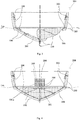
- FIG. 1 the section of any boat characterized by a hull 200 reinforced by a plurality of longitudinal members 202 and crosspieces 203 is shown. These reinforcing structures divide the inner surface of hull 200 in a plurality of substantially rectangular portions. As can be seen in the figure, each of these portions is covered with an inflatable device 100 that initially is installed in a first deflated configuration which occupies the least possible space.
- Said inflatable devices 100 cover the entire inner surface of hull 200, both in the immersed and in the emerged part of the latter.
- Each inflatable device 100 is connected to at least one dispenser 103, in turn connected to at least one activation means 104.
- each activation means 104 corresponds to a single dispenser 103 and each dispenser 103 corresponds to a single inflatable device 100.
- the same hull 200 of the previous figure is shown crashing against a cliff, getting severely damaged.
- the corresponding inflatable devices 100 have been inflated with non-inflammable foam 106 dispensed by dispensers 103 and irreversibly expanded within said inflatable devices 100 to a second inflated configuration, characterized by a significantly larger volume than said first deflated configuration.
- the actuation of the activation means 104 connected, through dispensers 103, to the inflatable devices 100 relative to the damaged hull portion 200 can also be automatic by installing, in the space existing between said inflatable devices 100 and the inner surface of hull 200, a plurality of wet sensors 110.
- said wet sensors 110 detect an amount of water greater than a certain preset tolerance threshold, they report the anomaly to processor 109 and, without requiring the user's manual control, the appropriate activation means 104 are automatically actuated.
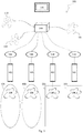
- processor 109 The operation of processor 109 is shown in FIG. 5 , where we can see that also two other types of sensors may be installed: operation sensors 102 and inertial sensors 111.
- the first ones are responsible for a functionality check that the system carries out automatically at predetermined time intervals. The results of this check are displayed to the user on the communication interface 101 that consists of a common electronic device.
- the presence of these operation sensors 102 allows the timely replacement or repair of any component of the safety system, thereby preventing unexpected malfunctions.
- the inertial sensors 111 are capable of detecting collisions and are set at a certain tolerance threshold. When a collision is detected that exceeds this threshold, also in this case processor 109 automatically causes the actuation of the appropriate activation means 104.
- foam 106 that expands within the inflatable devices 100 is non-inflammable
- foam 106 that expands within the inflatable devices 100 is non-inflammable
- a plurality of dispensers 103 are installed, connected to the respective activation means 104 which, after the switching of the inflatable devices 100 from the first deflated configuration to the second inflated configuration, expand in these compartments a particular, non-inflammable, sublimating foam 106.a which fills all the remaining volume.
- the characteristic of this second type of non-inflammable sublimating foam 106.a is that it is intended to sublimate within a known time interval from the moment of its expansion.
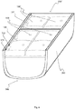
- FIGS. 6 and 7 a possible variant of the invention is shown, in this case installed on a tanker adapted to carry highly inflammable liquids within its compartments 300-300' .
- the safety system of the present invention in this case consists of a plurality of reversibly inflatable devices 100' installed in each compartment 300-300'.
- Each of said reversibly inflatable devices 100' is connected to a gas dispenser 107, in turn connected to the relative activation means 104, controlled by the control system 105'.
- At least one pressure sensor 320 is installed at each compartment 300-300' which, if an internal pressure exceeding a certain tolerance threshold is detected, is adapted, by means of said processor 109, to open the corresponding vent valve 310 to release said evaporation gases out of compartment 300-300', returning the internal pressure back to an acceptable value.
- said reversibly inflatable devices 100' are returned to the deflated configuration by the control system 105' by opening valve 108 located on the surface of each reversibly inflatable device 100'.
Landscapes
- Health & Medical Sciences (AREA)
- Public Health (AREA)
- Business, Economics & Management (AREA)
- Emergency Management (AREA)
- Engineering & Computer Science (AREA)
- Ocean & Marine Engineering (AREA)
- Chemical & Material Sciences (AREA)
- Combustion & Propulsion (AREA)
- Mechanical Engineering (AREA)
- Fire-Extinguishing By Fire Departments, And Fire-Extinguishing Equipment And Control Thereof (AREA)
- Emergency Lowering Means (AREA)
- Chemical Or Physical Treatment Of Fibers (AREA)
- Respiratory Apparatuses And Protective Means (AREA)
Claims (9)
- Versenkschutz- und Brandschutzsicherheitssystem für Boote, wobei das System aus einer Mehrzahl von aufblasbaren Vorrichtungen (100) von im Wesentlichen rechteckiger, abgeflachter Form besteht, wenn sie entleert sind, deren vier Umfangskanten mit einem Teil von zwei vorzugsweise aufeinanderfolgenden Längselementen (202) und mit einem Teil von zwei vorzugsweise aufeinanderfolgenden Querstücken (203) eines beliebigen Rumpfes (200) verbunden werden können; jede aufblasbare Vorrichtung (100) ist anfänglich in einer ersten, nicht aufgeblasenen Konfiguration installiert, in der sie den geringstmöglichen Raum einnimmt, und die aufblasbaren Vorrichtungen (100) eine zweite, aufgeblasene Konfiguration annehmen können, mit einem Volumen, das erheblich größer ist als die erste, nicht aufgeblasene Konfiguration; wobei jede der aufblasbaren Vorrichtungen (100) mit mindestens einer Ausgabeeinrichtung (103) verbunden ist, die dazu angepasst ist, die entsprechende aufblasbare Vorrichtung (100) mit einer vorbestimmten Menge nicht entflammbaren Schaums (106) zu füllen, der dazu angepasst ist, innerhalb der aufblasbaren Vorrichtung (100) expandiert zu werden, bis es ihr erlaubt wird, das gewünschte, im Voraus festgelegte maximale Volumen in der zweiten aufgeblasenen Konfiguration anzunehmen; wobei der nicht entflammbare Schaum (106) aus einem beliebigen, auf dem Markt erhältlichen Polymer, vorzugsweise aus geschäumtem Polyurethan, besteht, das dazu angepasst ist, das Volumen schnell zu vergrößern, sobald es sich außerhalb der Ausgabeeinrichtung (103) befindet, und das dazu angepasst ist, die Eigenschaften der Feuerbeständigkeit und des Auftriebs über einen längeren Zeitraum beizubehalten; wobei jeder der Ausgabeeinrichtungen (103) mit mindestens einem Aktivierungsmittel (104) verbunden ist, das dazu angepasst ist, die entsprechende Ausgabeeinrichtung (103) mittels einer Fernsteuerung des Benutzers, die über ein gewöhnliches Steuersystem (105) gesendet wird, zu aktivieren; wobei das Sicherheitssystem dadurch gekennzeichnet ist, dass es durch eine Mehrzahl von Ausgabeeinrichtungen (103) gebildet wird, die mit dem entsprechenden Aktivierungsmittel (104) verbunden sind, dazu dazu angepasst ist, durch eine Fernsteuerung des Benutzers, die mittels des Steuersystems (105) gesendet wird, eine vorbestimmte Menge nicht entflammbaren Schaums (106.a) im Inneren des unteren technischen Innenraums (201) und insbesondere zwischen den freien Räumen, die zwischen den bereits aufgeblasenen aufblasbaren Vorrichtungen (100) vorhanden sind, und in jedem anderen Innenraum des Schiffs, der als brandgefährdeter Raum (204) angesehen wird, zu expandieren; wobei der nicht entflammbare Schaum (106.a) dazu angepasst ist, nach einem bekannten Zeitintervall ab seiner Ausdehnung zu sublimieren; wobei das Steuersystem (105) durch einen gemeinsamen Prozessor (109) gebildet wird, der dazu angepasst ist, es dem Benutzer zu ermöglichen, mittels einer Kommunikationsschnittstelle (101) einen Teil oder die Gesamtheit der Aktivierungsmittel (104), falls sich im Rumpf (200) ein Leck auftut oder im Falle der Brandgefahr an Bord zu betätigen.
- Versenkschutz- und Brandschutzsicherheitssystem für Boote gemäß dem vorhergehenden Anspruch, dadurch gekennzeichnet, dass jede Ausgabeeinrichtungen (103) mit nur einer aufblasbaren Vorrichtung (100) verbunden ist.
- Versenkschutz- und Brandschutzsicherheitssystem für Boote nach einem der vorhergehenden Ansprüche 1 oder 2, dadurch gekennzeichnet, dass jedes Aktivierungsmittel (104) mit nur einer Ausgabeeinrichtung (103) verbunden ist.
- Versenkschutz- und Brandschutzsicherheitssystem für Boote nach einem der vorstehenden Ansprüche, dadurch gekennzeichnet, dass die Verbindung jeder Seite des Umfangs jeder aufblasbaren Vorrichtung (100) mit den jeweiligen Teilen zweier Längselemente (202) und zweier aufeinanderfolgender Querstücke (203) von vollkommen luftdichter Art ist.
- Versenkschutz- und Brandschutzsicherheitssystem für Boote nach einem der vorhergehenden Ansprüche, dadurch gekennzeichnet, dass die Außenfläche jeder aufblasbaren Vorrichtung (100) auf der dem Rumpf (200) zugewandten Seite mit einer Mehrzahl von Nässesensoren (110) versehen ist, die dazu angepasst sind, den möglichen Eintritt von Wasser in das Innere des Rumpfes (200) zu detektieren, wobei die Nässesensoren (110) auch dazu angepasst sind, mittels des Prozessors (109) des Steuersystems (105) automatisch das Aktivierungsmittel (104) bezüglich der aufblasbaren Vorrichtung (100), an der das Leck detektiert wurde, zu betätigen, wenn der Wassereintritt einen vorbestimmten Toleranzschwellenwert überschreitet.
- Versenkschutz- und Brandschutzsicherheitssystem für Boote gemäß einem der vorhergehenden Ansprüche, dadurch gekennzeichnet, dass die aufblasbaren Vorrichtungen (100) so ausgebildet sind, dass sie die gesamte Innenfläche des Rumpfes (200) bedecken, sowohl für den eingetauchten Teil des Rumpfes als auch für den oberen Teil des Rumpfes über Wasser.
- Versenkschutz- und Brandschutzsicherheitssystem für Boote gemäß einem der vorhergehenden Ansprüche, dadurch gekennzeichnet, dass das Steuersystem (105) auch mit einer Mehrzahl von mit dem Prozessor (109) verbundenen Betriebssensoren (110) versehen ist, die dazu angepasst sind, in vorbestimmten Zeitintervallen eine Überprüfung des Betriebs des gesamten Systems durchzuführen, und dazu angepasst sind, dem Benutzer das Ergebnis der Überprüfung mittels der genannten Kommunikationsschnittstelle (101) mitzuteilen.
- Versenkschutz- und Brandschutzsicherheitssystem für Boote gemäß einem der vorhergehenden Ansprüche, dadurch gekennzeichnet, dass alle Aktivierungsmittel (104) mit mindestens einem Trägheitssensor (111) verbunden sind, der dazu angepasst ist, die genannten Aktivierungsmittel (104) automatisch zu betätigen, wenn ein Aufprall oder eine Krängung festgestellt wurde, der/die einen vorbestimmten Toleranzschwellenwert überschritten hat.
- Versenkschutz- und Brandschutzsicherheitssystem für Boote gemäß einem der vorhergehenden Ansprüche, dadurch gekennzeichnet, dass das Steuersystem (105) dem Benutzer die Möglichkeit gibt, auszuwählen, welches der Aktivierungsmittel (104) basieren auf der Grundlage der Platzierung des Lecks, das mittels der Kommunikationsschnittstelle (101) angezeigt wird, zu aktivieren ist.
Applications Claiming Priority (2)
| Application Number | Priority Date | Filing Date | Title |
|---|---|---|---|
| ITUA2016A003781A ITUA20163781A1 (it) | 2016-05-25 | 2016-05-25 | Sistema di sicurezza antiaffondamento e antincendio per imbarcazioni. |
| PCT/IB2017/052764 WO2017203383A1 (en) | 2016-05-25 | 2017-05-11 | Anti-sinking and anti-fire safety system for boats |
Publications (2)
| Publication Number | Publication Date |
|---|---|
| EP3464052A1 EP3464052A1 (de) | 2019-04-10 |
| EP3464052B1 true EP3464052B1 (de) | 2020-07-08 |
Family
ID=56990796
Family Applications (1)
| Application Number | Title | Priority Date | Filing Date |
|---|---|---|---|
| EP17729921.1A Active EP3464052B1 (de) | 2016-05-25 | 2017-05-11 | Versenkungsschutz- und brandschutzsicherheitssystem für boote |
Country Status (4)
| Country | Link |
|---|---|
| US (1) | US11191984B2 (de) |
| EP (1) | EP3464052B1 (de) |
| IT (1) | ITUA20163781A1 (de) |
| WO (1) | WO2017203383A1 (de) |
Families Citing this family (3)
| Publication number | Priority date | Publication date | Assignee | Title |
|---|---|---|---|---|
| GB201604329D0 (en) * | 2016-03-14 | 2016-04-27 | Univ Strathclyde | Methods and systems for improving stability of a ship |
| IT201700108436A1 (it) * | 2018-02-02 | 2019-08-02 | Roberto Montelatici | Sistema di galleggiamento di emergenza di piccole imbarcazioni soggette a rischio affondamento |
| CN116176759B (zh) * | 2023-04-24 | 2023-07-28 | 江苏新时代造船有限公司 | 一种船用独立lng储舱 |
Family Cites Families (7)
| Publication number | Priority date | Publication date | Assignee | Title |
|---|---|---|---|---|
| DE2525202A1 (de) * | 1975-06-06 | 1976-12-23 | Hermann Hasse | Yacht-rettungsgeraet |
| WO1988000882A1 (en) * | 1986-07-30 | 1988-02-11 | Frank Arthur Rogers | Expansible means |
| CN1293634A (zh) * | 1998-03-21 | 2001-05-02 | 赖纳·塞德尔 | 具有防沉结构的水上交通工具 |
| US6098563A (en) * | 1998-08-10 | 2000-08-08 | Walker; Evan Harris | Tanker spillage protection system |
| US20060016380A1 (en) | 2003-10-24 | 2006-01-26 | Michael Braitberg | Electronic deployment system and method for inflating a flotation device |
| WO2008096095A1 (en) | 2007-02-07 | 2008-08-14 | The Linden Shield Limited | Valve assembly |
| CN202201150U (zh) * | 2011-07-17 | 2012-04-25 | 郭良 | 一种提高安全性的船 |
-
2016
- 2016-05-25 IT ITUA2016A003781A patent/ITUA20163781A1/it unknown
-
2017
- 2017-05-11 US US16/304,208 patent/US11191984B2/en not_active Expired - Fee Related
- 2017-05-11 EP EP17729921.1A patent/EP3464052B1/de active Active
- 2017-05-11 WO PCT/IB2017/052764 patent/WO2017203383A1/en not_active Ceased
Non-Patent Citations (1)
| Title |
|---|
| None * |
Also Published As
| Publication number | Publication date |
|---|---|
| WO2017203383A1 (en) | 2017-11-30 |
| EP3464052A1 (de) | 2019-04-10 |
| US20200316417A1 (en) | 2020-10-08 |
| US11191984B2 (en) | 2021-12-07 |
| ITUA20163781A1 (it) | 2017-11-25 |
Similar Documents
| Publication | Publication Date | Title |
|---|---|---|
| KR101235248B1 (ko) | 순간 충격에 능동 대응이 가능한 선박의 침몰 방지 장치 | |
| US11191984B2 (en) | Anti-sinking and anti-fire safety system for boats | |
| CN104875863A (zh) | 一种船舶防倾覆装置 | |
| JP4814120B2 (ja) | 船舶の復原力回復装置及びこれを備えた自動車運搬船 | |
| WO1995015279A1 (en) | Control of pneumatic devices | |
| US6327988B1 (en) | Ship with a protection system making it unsinkable | |
| CN1465500A (zh) | 船舶自动应急避碰减摇脱浅抗沉防倾覆装置 | |
| WO2013114184A1 (en) | Anti-sinking emergency device by automatic ejection and inflation of balloons | |
| KR101293480B1 (ko) | 선박 침몰 방지장치 | |
| KR101152059B1 (ko) | 선박의 복원력 회복 장치 및 이것을 구비한 자동차 운반선 | |
| WO1990008691A1 (en) | Buoyancy and stability apparatus | |
| EP2305555B1 (de) | Vorrichtung zur wiederherstellung eines aufrichtenden moments für ein schiff und damit ausgestattetes kraftfahrzeuge beförderndes schiff | |
| US20060016380A1 (en) | Electronic deployment system and method for inflating a flotation device | |
| US7412939B2 (en) | Emergency buoyancy system | |
| CN204713397U (zh) | 一种船舶防倾覆装置 | |
| US8087370B2 (en) | Ship stability recovery system and car carrier equipped with the same | |
| KR102086037B1 (ko) | 전복지연장치가 구비된 선박 | |
| KR100563635B1 (ko) | 침몰 방지 시스템이 설치된 선박 | |
| US20110102201A1 (en) | Method and system for stabilizing a vessel | |
| KR20110012040U (ko) | 부력보충용 팽창튜브를 갖는 선박 | |
| RU63769U1 (ru) | Система спасения терпящих бедствие кораблей | |
| EP3192734B1 (de) | Eintauchverhinderungssystem für schiffe und schiff damit | |
| KR20250124586A (ko) | 소형 선박의 침몰 방지를 위한 부력유지용 에어백장치 | |
| JPH03213493A (ja) | ガスバッグ式船舶救難装置 | |
| JP2005239073A (ja) | 船舶用脱出装置およびこれを備えた船舶 |
Legal Events
| Date | Code | Title | Description |
|---|---|---|---|
| STAA | Information on the status of an ep patent application or granted ep patent |
Free format text: STATUS: UNKNOWN |
|
| STAA | Information on the status of an ep patent application or granted ep patent |
Free format text: STATUS: THE INTERNATIONAL PUBLICATION HAS BEEN MADE |
|
| PUAI | Public reference made under article 153(3) epc to a published international application that has entered the european phase |
Free format text: ORIGINAL CODE: 0009012 |
|
| STAA | Information on the status of an ep patent application or granted ep patent |
Free format text: STATUS: REQUEST FOR EXAMINATION WAS MADE |
|
| 17P | Request for examination filed |
Effective date: 20181127 |
|
| AK | Designated contracting states |
Kind code of ref document: A1 Designated state(s): AL AT BE BG CH CY CZ DE DK EE ES FI FR GB GR HR HU IE IS IT LI LT LU LV MC MK MT NL NO PL PT RO RS SE SI SK SM TR |
|
| AX | Request for extension of the european patent |
Extension state: BA ME |
|
| DAV | Request for validation of the european patent (deleted) | ||
| GRAP | Despatch of communication of intention to grant a patent |
Free format text: ORIGINAL CODE: EPIDOSNIGR1 |
|
| STAA | Information on the status of an ep patent application or granted ep patent |
Free format text: STATUS: GRANT OF PATENT IS INTENDED |
|
| INTG | Intention to grant announced |
Effective date: 20200116 |
|
| GRAS | Grant fee paid |
Free format text: ORIGINAL CODE: EPIDOSNIGR3 |
|
| GRAA | (expected) grant |
Free format text: ORIGINAL CODE: 0009210 |
|
| STAA | Information on the status of an ep patent application or granted ep patent |
Free format text: STATUS: THE PATENT HAS BEEN GRANTED |
|
| AK | Designated contracting states |
Kind code of ref document: B1 Designated state(s): AL AT BE BG CH CY CZ DE DK EE ES FI FR GB GR HR HU IE IS IT LI LT LU LV MC MK MT NL NO PL PT RO RS SE SI SK SM TR |
|
| AX | Request for extension of the european patent |
Extension state: BA ME |
|
| REG | Reference to a national code |
Ref country code: CH Ref legal event code: EP Ref country code: AT Ref legal event code: REF Ref document number: 1288171 Country of ref document: AT Kind code of ref document: T Effective date: 20200715 |
|
| REG | Reference to a national code |
Ref country code: DE Ref legal event code: R096 Ref document number: 602017019434 Country of ref document: DE |
|
| REG | Reference to a national code |
Ref country code: IE Ref legal event code: FG4D |
|
| REG | Reference to a national code |
Ref country code: LT Ref legal event code: MG4D |
|
| REG | Reference to a national code |
Ref country code: AT Ref legal event code: MK05 Ref document number: 1288171 Country of ref document: AT Kind code of ref document: T Effective date: 20200708 |
|
| REG | Reference to a national code |
Ref country code: NL Ref legal event code: MP Effective date: 20200708 |
|
| PG25 | Lapsed in a contracting state [announced via postgrant information from national office to epo] |
Ref country code: FI Free format text: LAPSE BECAUSE OF FAILURE TO SUBMIT A TRANSLATION OF THE DESCRIPTION OR TO PAY THE FEE WITHIN THE PRESCRIBED TIME-LIMIT Effective date: 20200708 Ref country code: SE Free format text: LAPSE BECAUSE OF FAILURE TO SUBMIT A TRANSLATION OF THE DESCRIPTION OR TO PAY THE FEE WITHIN THE PRESCRIBED TIME-LIMIT Effective date: 20200708 Ref country code: AT Free format text: LAPSE BECAUSE OF FAILURE TO SUBMIT A TRANSLATION OF THE DESCRIPTION OR TO PAY THE FEE WITHIN THE PRESCRIBED TIME-LIMIT Effective date: 20200708 Ref country code: PT Free format text: LAPSE BECAUSE OF FAILURE TO SUBMIT A TRANSLATION OF THE DESCRIPTION OR TO PAY THE FEE WITHIN THE PRESCRIBED TIME-LIMIT Effective date: 20201109 Ref country code: HR Free format text: LAPSE BECAUSE OF FAILURE TO SUBMIT A TRANSLATION OF THE DESCRIPTION OR TO PAY THE FEE WITHIN THE PRESCRIBED TIME-LIMIT Effective date: 20200708 Ref country code: LT Free format text: LAPSE BECAUSE OF FAILURE TO SUBMIT A TRANSLATION OF THE DESCRIPTION OR TO PAY THE FEE WITHIN THE PRESCRIBED TIME-LIMIT Effective date: 20200708 Ref country code: NO Free format text: LAPSE BECAUSE OF FAILURE TO SUBMIT A TRANSLATION OF THE DESCRIPTION OR TO PAY THE FEE WITHIN THE PRESCRIBED TIME-LIMIT Effective date: 20201008 Ref country code: GR Free format text: LAPSE BECAUSE OF FAILURE TO SUBMIT A TRANSLATION OF THE DESCRIPTION OR TO PAY THE FEE WITHIN THE PRESCRIBED TIME-LIMIT Effective date: 20201009 Ref country code: ES Free format text: LAPSE BECAUSE OF FAILURE TO SUBMIT A TRANSLATION OF THE DESCRIPTION OR TO PAY THE FEE WITHIN THE PRESCRIBED TIME-LIMIT Effective date: 20200708 Ref country code: BG Free format text: LAPSE BECAUSE OF FAILURE TO SUBMIT A TRANSLATION OF THE DESCRIPTION OR TO PAY THE FEE WITHIN THE PRESCRIBED TIME-LIMIT Effective date: 20201008 |
|
| PG25 | Lapsed in a contracting state [announced via postgrant information from national office to epo] |
Ref country code: LV Free format text: LAPSE BECAUSE OF FAILURE TO SUBMIT A TRANSLATION OF THE DESCRIPTION OR TO PAY THE FEE WITHIN THE PRESCRIBED TIME-LIMIT Effective date: 20200708 Ref country code: RS Free format text: LAPSE BECAUSE OF FAILURE TO SUBMIT A TRANSLATION OF THE DESCRIPTION OR TO PAY THE FEE WITHIN THE PRESCRIBED TIME-LIMIT Effective date: 20200708 Ref country code: PL Free format text: LAPSE BECAUSE OF FAILURE TO SUBMIT A TRANSLATION OF THE DESCRIPTION OR TO PAY THE FEE WITHIN THE PRESCRIBED TIME-LIMIT Effective date: 20200708 Ref country code: IS Free format text: LAPSE BECAUSE OF FAILURE TO SUBMIT A TRANSLATION OF THE DESCRIPTION OR TO PAY THE FEE WITHIN THE PRESCRIBED TIME-LIMIT Effective date: 20201108 |
|
| PG25 | Lapsed in a contracting state [announced via postgrant information from national office to epo] |
Ref country code: NL Free format text: LAPSE BECAUSE OF FAILURE TO SUBMIT A TRANSLATION OF THE DESCRIPTION OR TO PAY THE FEE WITHIN THE PRESCRIBED TIME-LIMIT Effective date: 20200708 |
|
| REG | Reference to a national code |
Ref country code: DE Ref legal event code: R097 Ref document number: 602017019434 Country of ref document: DE |
|
| PG25 | Lapsed in a contracting state [announced via postgrant information from national office to epo] |
Ref country code: EE Free format text: LAPSE BECAUSE OF FAILURE TO SUBMIT A TRANSLATION OF THE DESCRIPTION OR TO PAY THE FEE WITHIN THE PRESCRIBED TIME-LIMIT Effective date: 20200708 Ref country code: SM Free format text: LAPSE BECAUSE OF FAILURE TO SUBMIT A TRANSLATION OF THE DESCRIPTION OR TO PAY THE FEE WITHIN THE PRESCRIBED TIME-LIMIT Effective date: 20200708 Ref country code: IT Free format text: LAPSE BECAUSE OF FAILURE TO SUBMIT A TRANSLATION OF THE DESCRIPTION OR TO PAY THE FEE WITHIN THE PRESCRIBED TIME-LIMIT Effective date: 20200708 Ref country code: RO Free format text: LAPSE BECAUSE OF FAILURE TO SUBMIT A TRANSLATION OF THE DESCRIPTION OR TO PAY THE FEE WITHIN THE PRESCRIBED TIME-LIMIT Effective date: 20200708 Ref country code: DK Free format text: LAPSE BECAUSE OF FAILURE TO SUBMIT A TRANSLATION OF THE DESCRIPTION OR TO PAY THE FEE WITHIN THE PRESCRIBED TIME-LIMIT Effective date: 20200708 Ref country code: CZ Free format text: LAPSE BECAUSE OF FAILURE TO SUBMIT A TRANSLATION OF THE DESCRIPTION OR TO PAY THE FEE WITHIN THE PRESCRIBED TIME-LIMIT Effective date: 20200708 |
|
| PLBE | No opposition filed within time limit |
Free format text: ORIGINAL CODE: 0009261 |
|
| STAA | Information on the status of an ep patent application or granted ep patent |
Free format text: STATUS: NO OPPOSITION FILED WITHIN TIME LIMIT |
|
| PG25 | Lapsed in a contracting state [announced via postgrant information from national office to epo] |
Ref country code: AL Free format text: LAPSE BECAUSE OF FAILURE TO SUBMIT A TRANSLATION OF THE DESCRIPTION OR TO PAY THE FEE WITHIN THE PRESCRIBED TIME-LIMIT Effective date: 20200708 |
|
| 26N | No opposition filed |
Effective date: 20210409 |
|
| PG25 | Lapsed in a contracting state [announced via postgrant information from national office to epo] |
Ref country code: SK Free format text: LAPSE BECAUSE OF FAILURE TO SUBMIT A TRANSLATION OF THE DESCRIPTION OR TO PAY THE FEE WITHIN THE PRESCRIBED TIME-LIMIT Effective date: 20200708 |
|
| PGFP | Annual fee paid to national office [announced via postgrant information from national office to epo] |
Ref country code: FR Payment date: 20210527 Year of fee payment: 5 Ref country code: DE Payment date: 20210527 Year of fee payment: 5 |
|
| PG25 | Lapsed in a contracting state [announced via postgrant information from national office to epo] |
Ref country code: SI Free format text: LAPSE BECAUSE OF FAILURE TO SUBMIT A TRANSLATION OF THE DESCRIPTION OR TO PAY THE FEE WITHIN THE PRESCRIBED TIME-LIMIT Effective date: 20200708 |
|
| PGFP | Annual fee paid to national office [announced via postgrant information from national office to epo] |
Ref country code: GB Payment date: 20210527 Year of fee payment: 5 |
|
| REG | Reference to a national code |
Ref country code: CH Ref legal event code: PL |
|
| PG25 | Lapsed in a contracting state [announced via postgrant information from national office to epo] |
Ref country code: MC Free format text: LAPSE BECAUSE OF FAILURE TO SUBMIT A TRANSLATION OF THE DESCRIPTION OR TO PAY THE FEE WITHIN THE PRESCRIBED TIME-LIMIT Effective date: 20200708 Ref country code: LI Free format text: LAPSE BECAUSE OF NON-PAYMENT OF DUE FEES Effective date: 20210531 Ref country code: LU Free format text: LAPSE BECAUSE OF NON-PAYMENT OF DUE FEES Effective date: 20210511 Ref country code: CH Free format text: LAPSE BECAUSE OF NON-PAYMENT OF DUE FEES Effective date: 20210531 |
|
| REG | Reference to a national code |
Ref country code: BE Ref legal event code: MM Effective date: 20210531 |
|
| PG25 | Lapsed in a contracting state [announced via postgrant information from national office to epo] |
Ref country code: IE Free format text: LAPSE BECAUSE OF NON-PAYMENT OF DUE FEES Effective date: 20210511 |
|
| PG25 | Lapsed in a contracting state [announced via postgrant information from national office to epo] |
Ref country code: BE Free format text: LAPSE BECAUSE OF NON-PAYMENT OF DUE FEES Effective date: 20210531 |
|
| REG | Reference to a national code |
Ref country code: DE Ref legal event code: R119 Ref document number: 602017019434 Country of ref document: DE |
|
| GBPC | Gb: european patent ceased through non-payment of renewal fee |
Effective date: 20220511 |
|
| PG25 | Lapsed in a contracting state [announced via postgrant information from national office to epo] |
Ref country code: FR Free format text: LAPSE BECAUSE OF NON-PAYMENT OF DUE FEES Effective date: 20220531 |
|
| PG25 | Lapsed in a contracting state [announced via postgrant information from national office to epo] |
Ref country code: GB Free format text: LAPSE BECAUSE OF NON-PAYMENT OF DUE FEES Effective date: 20220511 Ref country code: DE Free format text: LAPSE BECAUSE OF NON-PAYMENT OF DUE FEES Effective date: 20221201 |
|
| PG25 | Lapsed in a contracting state [announced via postgrant information from national office to epo] |
Ref country code: CY Free format text: LAPSE BECAUSE OF FAILURE TO SUBMIT A TRANSLATION OF THE DESCRIPTION OR TO PAY THE FEE WITHIN THE PRESCRIBED TIME-LIMIT Effective date: 20200708 |
|
| PG25 | Lapsed in a contracting state [announced via postgrant information from national office to epo] |
Ref country code: HU Free format text: LAPSE BECAUSE OF FAILURE TO SUBMIT A TRANSLATION OF THE DESCRIPTION OR TO PAY THE FEE WITHIN THE PRESCRIBED TIME-LIMIT; INVALID AB INITIO Effective date: 20170511 |
|
| PG25 | Lapsed in a contracting state [announced via postgrant information from national office to epo] |
Ref country code: MK Free format text: LAPSE BECAUSE OF FAILURE TO SUBMIT A TRANSLATION OF THE DESCRIPTION OR TO PAY THE FEE WITHIN THE PRESCRIBED TIME-LIMIT Effective date: 20200708 |
|
| PG25 | Lapsed in a contracting state [announced via postgrant information from national office to epo] |
Ref country code: MT Free format text: LAPSE BECAUSE OF FAILURE TO SUBMIT A TRANSLATION OF THE DESCRIPTION OR TO PAY THE FEE WITHIN THE PRESCRIBED TIME-LIMIT Effective date: 20200708 |
|
| PG25 | Lapsed in a contracting state [announced via postgrant information from national office to epo] |
Ref country code: TR Free format text: LAPSE BECAUSE OF FAILURE TO SUBMIT A TRANSLATION OF THE DESCRIPTION OR TO PAY THE FEE WITHIN THE PRESCRIBED TIME-LIMIT Effective date: 20200708 |