EP3463909B1 - Device and method for conveying substrates in a printing machine - Google Patents
Device and method for conveying substrates in a printing machine Download PDFInfo
- Publication number
- EP3463909B1 EP3463909B1 EP17724837.4A EP17724837A EP3463909B1 EP 3463909 B1 EP3463909 B1 EP 3463909B1 EP 17724837 A EP17724837 A EP 17724837A EP 3463909 B1 EP3463909 B1 EP 3463909B1
- Authority
- EP
- European Patent Office
- Prior art keywords
- carriage
- transport
- substrate
- rail
- substrates
- Prior art date
- Legal status (The legal status is an assumption and is not a legal conclusion. Google has not performed a legal analysis and makes no representation as to the accuracy of the status listed.)
- Active
Links
- 239000000758 substrate Substances 0.000 title claims description 326
- 238000007639 printing Methods 0.000 title claims description 159
- 238000000034 method Methods 0.000 title claims description 38
- 238000006073 displacement reaction Methods 0.000 claims description 92
- 238000001035 drying Methods 0.000 claims description 58
- 238000011282 treatment Methods 0.000 claims description 49
- 238000001514 detection method Methods 0.000 claims description 30
- 239000011248 coating agent Substances 0.000 claims description 17
- 238000000576 coating method Methods 0.000 claims description 17
- 238000007641 inkjet printing Methods 0.000 claims description 14
- 238000012546 transfer Methods 0.000 claims description 14
- 230000003287 optical effect Effects 0.000 claims description 9
- 238000000151 deposition Methods 0.000 claims description 7
- 239000000463 material Substances 0.000 claims description 7
- 238000003825 pressing Methods 0.000 claims description 5
- 239000000853 adhesive Substances 0.000 claims description 4
- 230000001070 adhesive effect Effects 0.000 claims description 4
- 239000010438 granite Substances 0.000 claims description 4
- 230000007246 mechanism Effects 0.000 claims description 4
- 230000003993 interaction Effects 0.000 claims description 3
- 239000004579 marble Substances 0.000 claims description 3
- 229910001018 Cast iron Inorganic materials 0.000 claims description 2
- 230000032258 transport Effects 0.000 description 315
- 238000012545 processing Methods 0.000 description 91
- 239000000976 ink Substances 0.000 description 42
- 230000008901 benefit Effects 0.000 description 24
- 238000005516 engineering process Methods 0.000 description 24
- 238000012423 maintenance Methods 0.000 description 16
- 230000005540 biological transmission Effects 0.000 description 14
- 238000004891 communication Methods 0.000 description 13
- 235000021183 entrée Nutrition 0.000 description 12
- 230000001133 acceleration Effects 0.000 description 11
- 230000004224 protection Effects 0.000 description 11
- 230000008569 process Effects 0.000 description 10
- 238000003860 storage Methods 0.000 description 10
- 238000004519 manufacturing process Methods 0.000 description 9
- 239000002966 varnish Substances 0.000 description 9
- 238000004140 cleaning Methods 0.000 description 8
- 210000004027 cell Anatomy 0.000 description 6
- 238000005259 measurement Methods 0.000 description 6
- 229910052782 aluminium Inorganic materials 0.000 description 5
- XAGFODPZIPBFFR-UHFFFAOYSA-N aluminium Chemical compound [Al] XAGFODPZIPBFFR-UHFFFAOYSA-N 0.000 description 5
- 230000000694 effects Effects 0.000 description 5
- 230000009467 reduction Effects 0.000 description 5
- 238000007514 turning Methods 0.000 description 5
- PLXMOAALOJOTIY-FPTXNFDTSA-N Aesculin Natural products OC[C@@H]1[C@@H](O)[C@H](O)[C@@H](O)[C@H](O)[C@H]1Oc2cc3C=CC(=O)Oc3cc2O PLXMOAALOJOTIY-FPTXNFDTSA-N 0.000 description 4
- 230000009471 action Effects 0.000 description 4
- 239000000919 ceramic Substances 0.000 description 4
- 230000008859 change Effects 0.000 description 4
- 239000012636 effector Substances 0.000 description 4
- 238000000265 homogenisation Methods 0.000 description 4
- 229910052751 metal Inorganic materials 0.000 description 4
- 239000002184 metal Substances 0.000 description 4
- 241000256815 Apocrita Species 0.000 description 3
- 239000004809 Teflon Substances 0.000 description 3
- 229920006362 Teflon® Polymers 0.000 description 3
- 230000002457 bidirectional effect Effects 0.000 description 3
- 230000006872 improvement Effects 0.000 description 3
- 239000002105 nanoparticle Substances 0.000 description 3
- -1 polytetrafluoroethylene Polymers 0.000 description 3
- 229920001343 polytetrafluoroethylene Polymers 0.000 description 3
- 239000004810 polytetrafluoroethylene Substances 0.000 description 3
- 230000004043 responsiveness Effects 0.000 description 3
- 238000013519 translation Methods 0.000 description 3
- 238000010146 3D printing Methods 0.000 description 2
- 239000004411 aluminium Substances 0.000 description 2
- 238000010420 art technique Methods 0.000 description 2
- 239000002131 composite material Substances 0.000 description 2
- 238000010276 construction Methods 0.000 description 2
- 238000003851 corona treatment Methods 0.000 description 2
- 230000001934 delay Effects 0.000 description 2
- 230000005611 electricity Effects 0.000 description 2
- 230000003631 expected effect Effects 0.000 description 2
- 239000000835 fiber Substances 0.000 description 2
- 238000007647 flexography Methods 0.000 description 2
- 239000011888 foil Substances 0.000 description 2
- 230000006870 function Effects 0.000 description 2
- 230000003116 impacting effect Effects 0.000 description 2
- 238000007603 infrared drying Methods 0.000 description 2
- 230000002452 interceptive effect Effects 0.000 description 2
- 238000009832 plasma treatment Methods 0.000 description 2
- 230000005855 radiation Effects 0.000 description 2
- 238000009877 rendering Methods 0.000 description 2
- 230000002441 reversible effect Effects 0.000 description 2
- 239000011435 rock Substances 0.000 description 2
- 229910001220 stainless steel Inorganic materials 0.000 description 2
- 239000010935 stainless steel Substances 0.000 description 2
- 235000019738 Limestone Nutrition 0.000 description 1
- 235000004443 Ricinus communis Nutrition 0.000 description 1
- 240000000528 Ricinus communis Species 0.000 description 1
- 229910000831 Steel Inorganic materials 0.000 description 1
- 239000004904 UV filter Substances 0.000 description 1
- 238000004458 analytical method Methods 0.000 description 1
- 238000000137 annealing Methods 0.000 description 1
- 230000009286 beneficial effect Effects 0.000 description 1
- 230000033228 biological regulation Effects 0.000 description 1
- 230000000903 blocking effect Effects 0.000 description 1
- 230000015556 catabolic process Effects 0.000 description 1
- 210000002421 cell wall Anatomy 0.000 description 1
- 229910010293 ceramic material Inorganic materials 0.000 description 1
- 239000004020 conductor Substances 0.000 description 1
- 239000000470 constituent Substances 0.000 description 1
- 238000002508 contact lithography Methods 0.000 description 1
- 230000008878 coupling Effects 0.000 description 1
- 238000010168 coupling process Methods 0.000 description 1
- 238000005859 coupling reaction Methods 0.000 description 1
- 238000005520 cutting process Methods 0.000 description 1
- 230000007547 defect Effects 0.000 description 1
- 238000006731 degradation reaction Methods 0.000 description 1
- 230000008021 deposition Effects 0.000 description 1
- 238000011161 development Methods 0.000 description 1
- 230000009977 dual effect Effects 0.000 description 1
- 230000008030 elimination Effects 0.000 description 1
- 238000003379 elimination reaction Methods 0.000 description 1
- 230000017525 heat dissipation Effects 0.000 description 1
- 238000003780 insertion Methods 0.000 description 1
- 230000037431 insertion Effects 0.000 description 1
- 230000010354 integration Effects 0.000 description 1
- JEIPFZHSYJVQDO-UHFFFAOYSA-N iron(III) oxide Inorganic materials O=[Fe]O[Fe]=O JEIPFZHSYJVQDO-UHFFFAOYSA-N 0.000 description 1
- 238000003698 laser cutting Methods 0.000 description 1
- 238000003754 machining Methods 0.000 description 1
- 230000000873 masking effect Effects 0.000 description 1
- 239000011159 matrix material Substances 0.000 description 1
- 239000005445 natural material Substances 0.000 description 1
- 230000037361 pathway Effects 0.000 description 1
- 239000008188 pellet Substances 0.000 description 1
- 239000004033 plastic Substances 0.000 description 1
- 238000012805 post-processing Methods 0.000 description 1
- 230000002028 premature Effects 0.000 description 1
- 238000002203 pretreatment Methods 0.000 description 1
- 238000004080 punching Methods 0.000 description 1
- 230000009257 reactivity Effects 0.000 description 1
- 238000005096 rolling process Methods 0.000 description 1
- 239000007787 solid Substances 0.000 description 1
- 238000007711 solidification Methods 0.000 description 1
- 230000008023 solidification Effects 0.000 description 1
- 239000010959 steel Substances 0.000 description 1
- 239000004575 stone Substances 0.000 description 1
- 230000001360 synchronised effect Effects 0.000 description 1
- 238000010200 validation analysis Methods 0.000 description 1
Images


Classifications
-
- B—PERFORMING OPERATIONS; TRANSPORTING
- B41—PRINTING; LINING MACHINES; TYPEWRITERS; STAMPS
- B41J—TYPEWRITERS; SELECTIVE PRINTING MECHANISMS, i.e. MECHANISMS PRINTING OTHERWISE THAN FROM A FORME; CORRECTION OF TYPOGRAPHICAL ERRORS
- B41J11/00—Devices or arrangements of selective printing mechanisms, e.g. ink-jet printers or thermal printers, for supporting or handling copy material in sheet or web form
- B41J11/02—Platens
- B41J11/06—Flat page-size platens or smaller flat platens having a greater size than line-size platens
-
- B—PERFORMING OPERATIONS; TRANSPORTING
- B41—PRINTING; LINING MACHINES; TYPEWRITERS; STAMPS
- B41J—TYPEWRITERS; SELECTIVE PRINTING MECHANISMS, i.e. MECHANISMS PRINTING OTHERWISE THAN FROM A FORME; CORRECTION OF TYPOGRAPHICAL ERRORS
- B41J11/00—Devices or arrangements of selective printing mechanisms, e.g. ink-jet printers or thermal printers, for supporting or handling copy material in sheet or web form
- B41J11/0085—Using suction for maintaining printing material flat
-
- B—PERFORMING OPERATIONS; TRANSPORTING
- B41—PRINTING; LINING MACHINES; TYPEWRITERS; STAMPS
- B41J—TYPEWRITERS; SELECTIVE PRINTING MECHANISMS, i.e. MECHANISMS PRINTING OTHERWISE THAN FROM A FORME; CORRECTION OF TYPOGRAPHICAL ERRORS
- B41J13/00—Devices or arrangements of selective printing mechanisms, e.g. ink-jet printers or thermal printers, specially adapted for supporting or handling copy material in short lengths, e.g. sheets
- B41J13/10—Sheet holders, retainers, movable guides, or stationary guides
- B41J13/12—Sheet holders, retainers, movable guides, or stationary guides specially adapted for small cards, envelopes, or the like, e.g. credit cards, cut visiting cards
-
- B—PERFORMING OPERATIONS; TRANSPORTING
- B65—CONVEYING; PACKING; STORING; HANDLING THIN OR FILAMENTARY MATERIAL
- B65H—HANDLING THIN OR FILAMENTARY MATERIAL, e.g. SHEETS, WEBS, CABLES
- B65H5/00—Feeding articles separated from piles; Feeding articles to machines
- B65H5/04—Feeding articles separated from piles; Feeding articles to machines by movable tables or carriages
-
- B—PERFORMING OPERATIONS; TRANSPORTING
- B65—CONVEYING; PACKING; STORING; HANDLING THIN OR FILAMENTARY MATERIAL
- B65H—HANDLING THIN OR FILAMENTARY MATERIAL, e.g. SHEETS, WEBS, CABLES
- B65H7/00—Controlling article feeding, separating, pile-advancing, or associated apparatus, to take account of incorrect feeding, absence of articles, or presence of faulty articles
- B65H7/02—Controlling article feeding, separating, pile-advancing, or associated apparatus, to take account of incorrect feeding, absence of articles, or presence of faulty articles by feelers or detectors
-
- G—PHYSICS
- G06—COMPUTING; CALCULATING OR COUNTING
- G06K—GRAPHICAL DATA READING; PRESENTATION OF DATA; RECORD CARRIERS; HANDLING RECORD CARRIERS
- G06K13/00—Conveying record carriers from one station to another, e.g. from stack to punching mechanism
- G06K13/02—Conveying record carriers from one station to another, e.g. from stack to punching mechanism the record carrier having longitudinal dimension comparable with transverse dimension, e.g. punched card
- G06K13/07—Transporting of cards between stations
-
- B—PERFORMING OPERATIONS; TRANSPORTING
- B65—CONVEYING; PACKING; STORING; HANDLING THIN OR FILAMENTARY MATERIAL
- B65H—HANDLING THIN OR FILAMENTARY MATERIAL, e.g. SHEETS, WEBS, CABLES
- B65H2405/00—Parts for holding the handled material
- B65H2405/30—Other features of supports for sheets
- B65H2405/35—Means for moving support
- B65H2405/352—Means for moving support in closed loop
- B65H2405/3521—Means for moving support in closed loop rail guided means, e.g. without permanent interconnection
-
- B—PERFORMING OPERATIONS; TRANSPORTING
- B65—CONVEYING; PACKING; STORING; HANDLING THIN OR FILAMENTARY MATERIAL
- B65H—HANDLING THIN OR FILAMENTARY MATERIAL, e.g. SHEETS, WEBS, CABLES
- B65H2406/00—Means using fluid
- B65H2406/30—Suction means
- B65H2406/35—Other elements with suction surface, e.g. plate or wall
- B65H2406/351—Other elements with suction surface, e.g. plate or wall facing the surface of the handled material
-
- B—PERFORMING OPERATIONS; TRANSPORTING
- B65—CONVEYING; PACKING; STORING; HANDLING THIN OR FILAMENTARY MATERIAL
- B65H—HANDLING THIN OR FILAMENTARY MATERIAL, e.g. SHEETS, WEBS, CABLES
- B65H2553/00—Sensing or detecting means
- B65H2553/80—Arangement of the sensing means
- B65H2553/81—Arangement of the sensing means on a movable element
-
- B—PERFORMING OPERATIONS; TRANSPORTING
- B65—CONVEYING; PACKING; STORING; HANDLING THIN OR FILAMENTARY MATERIAL
- B65H—HANDLING THIN OR FILAMENTARY MATERIAL, e.g. SHEETS, WEBS, CABLES
- B65H2555/00—Actuating means
- B65H2555/10—Actuating means linear
- B65H2555/13—Actuating means linear magnetic, e.g. induction motors
Definitions
- the present invention relates to the field of printing, in particular to the field of digital printing without contact with the substrates, and more particularly to a device and a method making it possible to transport printable and printed substrates on all the workstations treatment included in a printing machine, the transport of the substrates being carried out in such a way as to allow them to be printed under optimal conditions.
- Transporting substrates using automated processing or industrial manufacture is a particular technical challenge.
- Part of the difficulty lies in the movement of a substrate along a chain comprising several treatments of said substrate, in particular for its movement from one treatment station to the next treatment station during the process.
- fabrication/finishing of the final substrate Any device for processing a substrate, and more particularly any device for processing a substrate digitally, can advantageously benefit from the advantages of the present invention.
- the device for processing a substrate is selected from devices for laser cutting, finishing, drying, punching, cutting, folding, and/or in particular printing, in particular digital inkjet printing.
- the combination of several different printing and processing modes within the same machine requires a high-precision transport mode (for example to meet the requirements of printed electronics), as well as a transport whose the components do not interfere with the efficiency requirements of each of the printing stations and treatments individually and/or in combination; we will cite by way of illustration the negative impact that a processing station could have on the processing station which follows it and/or on the processing station which precedes it along the transport path (for example to prevent a station does not affect the performance of a print station).
- the implementation must be such that it makes it possible to convey the substrates of various sizes between all the processing stations in the best possible way while meeting the requirements linked to the different speeds of each of the processing stations as well as to production rates sufficient to allow an efficient and profitable industrial application.
- a system for transporting substrates in a printing machine, along a transport path oriented along a longitudinal axis from at least one input magazine supplying the printable substrates, to at least one magazine outlet receiving the substrates characterized in that it comprises: mobile gripping means, each comprising an opening/closing system ensuring the release or the gripping of a substrate, the said gripping means comprising front gripping means and rear, each gripping a part, respectively, front and rear, of the substrate along the transport path, guide means for guiding the gripping means along the transport path, at least one motorization means ensuring movement of the means gripping along the guide means, preferably with an independent movement between at least the front gripping means and the rear gripping means, the system of transport of substrates being thus adapted to grip each substrate of so as to tension and
- US2013293652 claims an apparatus for handling a sheet of substrate in a marking assembly, the apparatus comprising: a support track (lane) forming a closed path, a marking area for marking a sheet of substrate, and a carriage/platen movable along of the support track, the carriage/platen circulating around the closed path, the said carriage conveying the sheet of substrate in a process direction for at least part of the closed path through the marking area.
- the trolley is provided with front and rear rolling castors which support the trolley 80 along the support surfaces of the track, said track comprising side walls which hold the trolley appropriately therebetween thanks to the side wheels (provided with springs 86) which help to position the carriage laterally along the track 40.
- US2013293652 does not give an explanation of the mode of movement of the carriages and is content to cite the possibility of having an on-board motor, propulsion transmitted by a mechanism included in track 40, or a direct drive system using pulleys, cables, chains or other similar systems.
- FR2827807 claims a color printing device for portable objects (9) having a first face to be processed, characterized in that it comprises a frame (10) and a transport path (2) on which the objects to be processed are moved, these objects successively passing through at least two printing stations (31, 32) comprising printing means, printing all or part of this first face by a displacement, called longitudinal, of the object, this displacement being coordinated with the print order of said printing means, these printing means remaining stationary relative to the frame during printing.
- the present invention thus provides a new device and a new method for transporting printable and printed substrates in an accurate manner, adapted to substrates of various types, sizes and thicknesses.
- the invention makes it possible to produce prints with variable pitch.
- the present invention is suitable for printing machines without contact with the substrate, such as ink-jet printing machines and, more particularly printing machines which make it possible to combine, within the same machine, different types of printing and/or different types of drying and/or different types of pre-treatments and/or different types of post-treatments (or finishes) such as, purely by way of illustration and not limitation, contactless printing conventional inks (black, white, mono or polychrome), and/or varnish, and/or inks suitable for printed electronics, and/or inks suitable for three-dimensional printing and/or diverse and varied inks such as, for example, functional inks and/or insulating inks (for example, insulating inks used downstream of ink printing for printed electronics); and/or drying comprising, for example, an infrare
- An additional object of the invention is to provide a method for transporting printable substrates.
- the substrate is held flat in a stationary position relative to the table; however, as the present invention can also be applied to sheet-type substrates but also to any other type of three-dimensional object (for example cylinders, pens, telephone shells, etc.), the those skilled in the art will understand that the invention may advantageously also be suitable for these other objects without qualifying their immobile positioning as being “flat” on the table; according to a variant embodiment of the present invention, the upper part of the table will comprise a matrix comprising forms and/or receptacles in which these other types of three-dimensional objects can advantageously be deposited and/or fixed.
- any other type of three-dimensional object for example cylinders, pens, telephone shells, etc.
- the present invention also relates to the use of the claimed printing machine and/or method for transporting substrates in a printing machine comprising at least one contactless printing station, in particular digital jet printing station. 'ink. More particularly, this use is carried out in a printing machine which comprises at least two different contactless printing stations in series, the said printings being selected from the following list: printings of conventional inks (black, white, mono and /or polychrome), and/or varnish, and/or inks suitable for printed electronics, and/or inks suitable for three-dimensional printing and/or various and varied inks such as for example functional inks and/or insulating inks (for example insulating inks used downstream of ink printing for printed electronics); the combination in series on the transport loop of printing conventional inks, printing inks suitable for printed electronics (such as conductive inks based or not on nanoparticles) and printing varnish and/or functional inks and/or insulating inks, the whole being preferably carried out on the same substrate, is
- the claimed device and method differ from the prior art thanks to their flexibility of use and thanks to a reduction in manufacturing times as well as the corresponding costs, which makes them particularly attractive, in particular for printed electronics, for example for the manufacture of circuits printed.
- the transport device (and therefore the printing machine comprising one or more processing stations) is controlled by computer means which in particular control the various workstations, and also which collect information from the various sensors installed in the device.
- computer means do not have to be detailed in the present application and they could for example be integrated into the machine or deported in a separate device.
- the sensors give, for example, information on the positions of the substrates, information on the configurations of the substrates and/or validation information following an operation correctly carried out or not. Certain information necessary for the implementation of the invention can also be recorded beforehand in the computer means (for example via an entry on an interface by an operator).
- Such information can for example concern the shape and/or the dimensions of the substrates (for example their thickness), the power of the drying, the thickness of the layer of ink and/or varnish etc., but it is generally preferred that sensors measure or verify such information.
- the substrates awaiting printing are generally, in a manner known per se, placed in at least one input zone, for example an input magazine having a storage capacity defined according to the nature of the substrate and the needs for the impression.
- an input magazine is provided to accept several tens, hundreds, or even thousands of substrates of variable nature, thickness and size (for example and non-limiting manner of a format whose sides are of the order of a centimeter, for example an A10 type format, by way of more precise example a credit card type format; up to the format whose sides are of the order of several meters, for example an A0 type format or a 2 x 2 meter format).
- the substrates are directed to an output zone, for example stored in at least one output store generally having the same storage capacity as the input store.
- a characteristic of the present invention is therefore the use of a substrate conveyor (preferably of the carousel type) making it possible to guide and move the substrates through the processing stations, the said conveyor comprising carriages which hold the substrates in a stationary position (for example stationary and flat) and which move along the transport path, preferably on a fixed rail, which makes it possible to move each carriage/substrate assembly on the rail, and being characterized in that the movement of the carriages is controlled by means of a motorization system, preferably a linear motorization system.
- This linear motorization is based on the principle of an electromagnetic interaction between an assembly of coils (primary assembly) and a pathway of permanent magnets (secondary assembly), an interaction which transforms electrical energy into linear mechanical energy.
- the primary motor assembly of the linear motorization is part of the (mobile) carriage and the secondary assembly consists of a magnet channel (also called magnetic channel), the said track being fixed along the transport path; in variant embodiments, some of which will be described in more detail below in the description, said track is fixed to the fixed rail (or forms an integral part of the fixed rail) and/or is fixed to the base (or forms an integral part of the base) and/or is fixed to a rigid rail support structure (or is an integral part of this rigid structure); in these configurations, the primary assembly of a carriage therefore moves at the same speed as the substrate transported by said carriage.
- the trolley is therefore a trolley which can be qualified as an intelligent and/or autonomous trolley as described below in the description.
- the length of the magnet track is preferably similar to the length of the transport path and/or the transport loop (for example the length of the fixed rail). It is possible to envisage configurations in which the magnet channel is located on one side or the other side (or on both sides in a multi-track configuration) of the fixed rail.
- the total length of a magnet channel may have a length either identical to, or slightly greater than, or slightly less than that of the transport path and/or of the transport loop (for example that of the fixed rail); purely by way of illustration and not limitation, the magnet track will have a length between 0.8 times and 1.2 times the length of the transport path and/or the transport loop (for example the length of the fixed rail) , preferably between 0.9 times and 1.1 times the length of the transport path and/or of the transport loop (for example the length of the fixed rail).
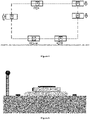
- the figure 1 schematically illustrates an overview of the substrate transport device according to the present invention.
- said conveyor comprising a fixed rail which forms a closed transport loop (a rectangle with rounded corners in the figure); carriages (three carriages in the figure) which hold the substrates (three rectangular substrates per carriage) in an immobile position (flat in the figure) and which move on said rail while transporting the substrates; the central fixed rail as well as the channel of magnets positioned in its center; the fixed base (the length of which is slightly less than a length of the side of the rectangle forming the transport loop in this illustration); as well as a simplified view of the electrically conductive rails which, in this configuration, form a closed loop (of the same shape as the transport loop) of greater length than that of the fixed rail because it is located outside the loop formed by the rail.
- the processing stations have not been shown; purely by way of illustration, the positioning of the printing stations along this transport loop will
- the picture 2 schematically illustrates a view of the secondary assembly which consists of a track of magnets (also called magnetic track), said track being in this illustration fixed to the fixed rail.
- a track of magnets also called magnetic track
- the picture 3 schematically illustrates an overview of the device for transporting substrates in a printing machine comprising several processing stations according to the present invention.
- the “Alphajet” block located at the top left of the figure and positioned in this configuration inside the loop corresponds to the printing and drying stations; in particular in this configuration a combination in series of a printing of conventional inks, of a printing of inks adapted to printed electronics (such as conductive inks based or not of nanoparticles) and an impression of varnish and/or functional inks and/or insulating inks.
- a characteristic of a preferred variant of the present invention is therefore the use of a substrate conveyor (preferably of the carousel type) making it possible to guide and move the substrates through the processing stations, the said conveyor comprising carriages which maintain the substrates in a stationary position (eg flat) and which move along the transport path (eg on a fixed rail) which forms a transport loop, for example a closed transport loop.
- the shape of the transport loop may be of any suitable type. Its length will itself be determined according to the number of processing stations included in the printing machine.
- the printing machine comprises at least one printing station without contact with the substrate (for example two, three, four or more printing stations) and at least one drying station (for example two, three, four or more drying stations);
- the printing station can advantageously be selected from a conventional ink jet printing station (black, white, mono and/or polychrome) and/or a varnish jet printing station, and/or a inkjet printing station suitable for printed electronics (for example conductive ink based or not on nanoparticles), and/or an inkjet printing station suitable for three-part printing dimensions and/or a various and varied inkjet printing station such as for example functional inks and/or insulating inks (for example insulating inks used downstream of an ink printing for printed electronics );
- the drying station can advantageously be selected from an infrared (IR) drying station and/or a near-infrared (NIR) drying station and/or a heated air current drying station, and/or a ultraviolet (UV) lamp drying station and/or UV
- pretreatment stations such as, for example, a corona treatment station, and/or a plasma treatment station, and/or a strip cleaning system (cleaning roller , brush, etc.), and/or a coating station (flexography, etc.), and/or a sheet turning system; and/or the optional use of one or more post-processing (or finishing) stations such as a sheet turning system and/or a coating station (for example by depositing an additional coating, for example gilding or other material) on the substrate, for example by means of a "gilding" depositing device, for example by applying/pressing a sheet (bearing said coating or gilding) on selected areas of the substrate (for example comprising a deposit of adhesive according to a predetermined pattern) so as to cause the desired part of the gilding-type sheet to adhere to the selected areas.
- pretreatment stations such as, for example, a corona treatment station, and/or a plasma treatment station, and/or a strip cleaning system (cleaning roller
- the present invention thus makes it possible to convey substrates of various dimensions/sizes between all the processing stations while meeting the requirements related to the speeds (whether they are different or identical) required during the passages of the substrates in each of the processing stations. as well as at sufficient manufacturing rates to allow an efficient and profitable industrial application.
- the motorization technology in particular the linear motorization technology, used for the transport of the substrates makes it possible to individually control the speed of each carriage; this thus makes it possible, on request, to accelerate or decelerate the speed of a carriage, or even to modify the relative speed of a carriage with respect to another carriage.
- the speed of at least one carriage (for transporting the substrates) moving along the transport loop is different from the speed of a another carriage (for transporting the substrates) moving along the transport loop; for example, the speed of at least one moving substrate transport carriage through a processing station is different from the speed of a moving substrate transport carriage either through another processing station transport loop or through other sections of the transport loop.
- This possibility of individually controlling the speed and/or the acceleration and/or the deceleration of each carriage during its movement along the transport path represents an exceptional advantage according to the present invention.
- This makes it possible to take full advantage of the performance of each of the treatment stations by adapting the speed of the trolley to the type of treatment desired.
- this The invention therefore also makes it possible to carry out printing and/or drying and/or various treatments with variable pitch.
- the transport loop does not include a right angle; on the contrary, its shape will preferably be selected so as to comprise only linear straight parts joined by means of free-form curves (“arcs”).
- the carriages do not perform curves (bends) during their movement and the loop comprises at least one rail (for example 2 parallel rails) located at a certain height and at least one rail (for example 2 rails parallel) perpendicular(s) to the first rail and located at another height which involve the use of a system allowing the carriage to be raised and/or lowered (such as an elevator) to pass from one rail to the other.
- the carriages do not perform curves (bends) during their movement and the loop comprises at least one rail (for example 2 parallel rails) located at a certain height and at least one rail (for example 2 rails parallel) perpendicular(s) to the first rail and located at another height which involve the use of a system allowing the carriage to be raised and/or lowered (such as an elevator) to pass from one rail to the other.
- the transport loop is square or rectangular in shape with rounded corners.
- the processing stations for example the printing and/or drying stations are located in a straight linear part of the transport loop.
- the usual direction of rotation of the carriages along the transport loop is generally defined according to the arrangement of the printing and/or drying stations and/or other substrate treatment station(s). It can therefore be clockwise or counterclockwise.
- Another advantage of the linear motor technology according to the present invention is that the direction of rotation can be reversed if necessary.
- the carriage and the substrate(s) maintained in an immobile position (for example flat) on the carriage can move in both directions along the along the transport path, for example in both directions of rotation on the transport loop.
- This feature allows for example to perform more than one pass through a printing station and/or a drying station and/or another substrate treatment station, and/or in a combination of two or more or all these aforementioned positions.
- a processing station may require repeated passage of the substrate so as to achieve the desired printing resolution (for a printing station) and/or the desired drying quality (for example for a of drying which one would not like to increase the drying power) and/or having to perform multi-passes when other treatment stations will not need it.
- Controlling the movements of the carriages autonomously therefore constitutes a considerable advantage of the present invention.
- the trolley is therefore a trolley that can be qualified as an intelligent and/or autonomous trolley as described in the present description.
- the substrates perform on their selected carriage only one passage along the transport path, for example only around the transport loop, from their holding in a stationary position (for example flat) on the carriage near the input magazine and storage of the substrates up to their point of removal from the same trolley near the output magazine and storage of the treated substrates.
- the substrate can make more than one pass through a printing station and/or a drying station and/or another substrate treatment station, and/or in a combination two or more or all of the aforementioned positions, without leaving his cart.
- This feature can be particularly useful when a printing station and/or a drying station and/or another substrate processing station does not achieve the required performance, for example in terms of resolution of the printed image for a printing station; thus, a second passage under the substation with lower performance will make it possible to solve the problem identified without having to urgently change the faulty substation.
- a preferred characteristic of an alternative embodiment of the present invention is therefore the use of a substrate conveyor (preferably of the carousel type) making it possible to guide and move the substrates through the processing stations, the said conveyor comprising a or more carriages which hold the substrates in a stationary position (eg flat) and which move on a fixed rail along the transport path (eg along the transport loop) during substrate treatments, and characterized in that at least part of the rail is fixed to a base, the surface of which is preferably flat; the length of the fixed rail preferably being identical to that of the transport path (for example of the transport loop).
- the figure 6 schematically illustrates this base - rail assembly.
- a granite plinth which constitutes the base in dark gray on which a fixed rail with double V-guide is fixed; there is an optional holding piece which is fixed on the fixed rail, on which are fixed - on its left a ruler which will be described in the description below - and on its top, the magnet track already described below -before.
- This figure 6 also very schematically illustrates elements which will be described in more detail in the description below, namely, on either side of the fixed rail slides fixed to the base and at the left end of the figure a set electrically conductive rails surmounted by a radiating data (information) transfer cable.
- the dimensions of the base will be selected according to the needs and applications.
- the upper flat surface of the base will be placed at a height from the ground of between 50 cm and 80 cm and will have a transverse width of between 40 cm and 120 cm, for example between 60 cm and 100 cm, and a length between 200 cm and 1200 cm, for example 500 cm and 800 cm.
- the total length of the base(s) of the transport device is selected so as to cover the entire space located below the printing stations of the transportation. More particularly, if the value of the total length of the printing stations is X, the total length of the base(s) of the transport device will be at least X, so as to guarantee the desired flatness under the stations printing; however, as this (these) base(s) represent a significant weight and financial investment, it will be preferred to limit their total length to values less than 3 times X, preferably less than 2 times X, for example less than 1.5 times X, see less than 1.2 times X.
- the total length of the base(s) of the transport device is also selected so as to cover the entire space located below the drying stations of the loop of transportation. More particularly, if the value of the total length of the drying stations is Y and the value of the total length of the printing stations is X, the total length of the base(s) of the transport device will be at least minus (X+Y), so as to guarantee the desired flatness under the drying and printing stations; however, as these base(s) represent a significant weight and financial investment, it is preferable to limit their total length to values less than 3 times (X+Y), preferably less than 2 times (X+Y) , for example less than 1.5 times (X+Y), or even less than 1.2 times (X+Y).
- the total length of the base(s) of the transport device is also selected so as to cover all the space located below the other processing stations (the stations which are neither printing nor drying) of the transport loop such as, by way of illustration, the pre- and/or post-treatment stations.
- the total length of the base(s) of the transport device will be at least (X+Y+Z), so as to guarantee the desired flatness under all the drying, printing and other treatment stations; however, as these base(s) represent a significant weight and financial investment, it is preferable to limit their total length to values less than 3 times (X+Y+Z), of preferably less than 2 times (X+Y+Z), for example less than 1.5 times (X+Y+Z), or even less than 1.2 times (X+Y+Z).
- the total length of the base(s) of the transport device is less than half the length of the transport path (for example of the transport loop), less than 0 .4 times the length of the transport path (for example of the transport loop), for example less than a third of the length of the transport path (for example of the transport loop).
- one, two or more pedestals will be placed in the transport device.
- the plinth provides the stable base/solid foundation for the carriage (and/or rail) along the transport path (e.g. along the transport loop) at the most critical locations such as under workstations. impression.
- the Applicant has found that the base makes it possible to effectively solve the vibration problems encountered with the transport devices of the prior art, which therefore makes it possible to improve the transport of printable and/or printed substrates on the whole processing stations included in a printing machine, in particular a printing machine without contact with the substrate, such as ink-jet printing machines.
- polishable firm rock such as granite, and/or basalt, and/or porphyry, and/or serpentinite, ... and/or gneiss, and /or sandstones, and/or breccias, and/or limestones and/or other conglomerates, as constituent element(s) of a base used in a preferred embodiment variant according to the present invention.
- the weight ratios between the base, the carriage and the substrate(s) also constitute important characteristics making it possible to combat the vibrations of the transport device; thus, in an alternative embodiment of the present invention, the ratio between the weight of a carriage of length L and the weight of a length L of the base will be less than 0.3, for example less than 0.2; in an alternative embodiment of the present invention, the ratio between the weight [of a carriage of length L and the substrates arranged on said carriage] and the weight of a length L of the base will be less than 0.3, by example less than 0.2.
- the system for guiding the carriages on the rail is selected from V-shaped guiding systems; preferably comprising a double V-guide as illustrated in the figure 6 (rail whose ends are in a “male” V) and the figure 7 (“female” V-wheels fixed to the trolley).
- the trolley comprises at least one V-wheel, preferably 2 V-wheels, more particularly at least 4 V-wheels.
- the system for guiding the carriage on the rail comprises at least one pair of guiding elements arranged on either side of the rail (for example wheels); each pair of guide elements (for example pair of wheels) comprising a mechanism ensuring the guidance of the carriage both in straight lines and in bends.
- each pair of guide elements will comprise a retaining bar which connects the two guide elements to each other (for example the two wheels to each other), the said retaining bar comprising a pivoting axis connected to the carriage making it possible to ensure optimum guidance of the carriage along the rail and, in particular along the bends formed by the transport loop.
- the system for guiding the carriage on the rail comprises 3 guiding elements (for example 3 wheels), 2 on one side of the rail and 1 on the other side of the rail so as to allow the trolley to take the turns formed by the transport loop and also to follow linear directions.
- the figure 7 therefore illustrates a variant of a carriage according to the present invention, said carriage comprising a structural base shown in light gray in the figure surmounted by a table (in dark gray) for supporting the substrates which will be detailed below in the description; you can also see under the base 2 V-shaped wheels surrounded by two sliders which will be detailed below in the description and, to the left of the base, a sliding contact element (used to supply energy to the trolley).
- a variant of the figure 7 (not shown) will be to arrange the wheels in a V such that they surround the runners of the slides, which will preferably imply that the rails of the slides will be positioned on the fixed rail and that the height of the sliders of the slides will be lower than that of the V-wheels under the base of the trolley.
- the trolley guidance system therefore comprises at least one rail coupled to the wheel(s) of the trolley according to a V-shaped guide device; this makes it possible to guide the wheel(s) of the trolley in the V(s) of the rail; preferably a rail with double V-guide, which allows the V-wheels of the trolley to be guided therein.
- the carriage is provided with 4 V-shaped wheels placed (preferably symmetrically two by two with respect to the center of the carriage), two of the wheels being guided by the V d one side of the rail and the other two wheels being guided by the V on the other side of the rail.
- the rail is positioned centrally with respect to the width of the carriage and/or the width of the base; thus, in an alternative embodiment of the present invention, the center of the width of the rail is at a distance of less than 20 cm, for example less than 15 cm from the center of the width of the carriage and/or from the center of the base width. In a particular embodiment of the present invention, the center of the width of the magnet track is aligned with the center of the width of the fixed rail.
- At least part of the rail is fixed to a base or forms an integral part of said base.
- a base over the entire length of the rail for its attachment.
- a hollow rigid structure is used for fixing the rail (or for integrating the rail into said structure) outside the printing stations and/or the drying stations and /or any other substrate processing station.
- the total length of the hollow rigid structure used for fixing the rail of the transport device is greater than or equal to half the length of the transport path (for example of the loop transport), greater than or equal to 0.6 times the length of said path (of the transport loop), for example greater than or equal to two thirds of said path (of the length of the transport loop).
- the transport device is equipped with at least one displacement detection system (or sensor), preferably a linear displacement detection system (or sensor), for measuring the displacement (position, speed, acceleration and/or deceleration) of the carriage along the transport path, for example relative to the fixed rail.
- a displacement detection system or sensor
- Any displacement detection system (or sensor) satisfying the required accuracy requirements can advantageously be used in the device according to the present invention.
- Mention will be made, by way of non-limiting illustration, of a displacement sensor “O” comprising a mobile part and a fixed part, for example an optical ruler.
- the fixed part of the displacement sensor preferably consists of a linear ruler preferably positioned along the transport path (of the transport loop) under printing stations and/or drying stations and/or under any other substrate processing station requiring increased precision in measuring the position, speed, acceleration and/or deceleration of the carriage along the transport path (from the transport loop), preferably under the printing stations.
- This rule preferably linear
- the carriage integrates at least one reader (preferably an optical reader) which constitutes the mobile part of the displacement sensor.
- the figure 1 schematically illustrates an overview of the substrate transport device according to the present invention.
- said conveyor comprising a fixed rail which forms a closed transport loop, and carriages which hold the substrates in an immobile position (for example flat ) and which move on the said rail transporting the substrates, the control of the movement being allowed thanks to the linear rule which, on this figure 1 , is confused with the fixed rail.
- the figure 6 also schematically illustrates the rule which is positioned in this configuration to the left of the optional holding piece which is fixed to the fixed rail.
- the transport device is equipped with at least one displacement detection system (a displacement sensor), preferably a linear displacement sensor, for measuring the displacement (position, speed, acceleration and/or deceleration ) of the trolley in relation to the processing station(s).
- a displacement detection system preferably a linear displacement sensor
- Any displacement sensor satisfying the required precision requirements can advantageously be used in the device according to the present invention. Mention will be made, by way of non-limiting illustration, of a displacement sensor “M” comprising a mobile part and a fixed part, for example a magnetic ruler.
- the movable part of the sensor (“movable” because it moves with the carriage) of displacement (for example of the magnetic sensor) preferably consists of a rule, preferably linear, fixed on the carriage, for example fixed along a longitudinal axis (that is to say parallel to the direction of movement of the carriage) on the carriage (or forming an integral part of the carriage).
- the presence of the rule, preferably linear thus makes it possible to determine at any time the positioning, the speed, the acceleration and/or the deceleration of the carriages along the transport path (for example on the transport loop) with respect to at the processing station(s).
- at least one processing station preferably at least one printing station, preferably all the stations printing, or even all processing stations, incorporate at least one reader (preferably a magnetic reader) which constitutes the fixed part of the displacement sensor.
- the transport device is equipped with at least one "O" displacement sensor to measure the displacement of the carriage relative to the transport path (for example the rail) and at least displacement sensor "M” for measuring the displacement of the carriage relative to the processing station.
- the "O" sensor reader and the "M” sensor ruler are located on the carriage.
- the rule of the "O" sensor is an integral part of the rail and/or is fixed to the rail and/or is fixed to the base of the rail and/or is an integral part of the base. of the rail and/or is attached to the rail structure and/or is an integral part of the rail structure.
- the reader of the "M” sensor is fixed to a fixed (or mobile) element of a printing station and/or of a drying station and/or of another processing station.
- the “O” sensor is an optical linear displacement sensor and the “M” sensor is a magnetic linear displacement sensor.
- the Applicant has discovered, thanks to the combination of these two displacement sensors, that it is possible to achieve an exceptional level of measurement precision (for example of the order of a micrometer on the critical sections of the transport loop, for example of the order of a micrometer over transport loop lengths of the order of a meter) thus allowing optimized management of the management of the positioning and/or the speed and/or the acceleration and/or the deceleration of the carriages along the transport path, for example along the transport loop.
- the dual positioning management of the readers/sensors as described above also brings other essential advantages to the present invention as described below.
- the fact of arranging the reader of the "O" sensor on the carriage makes it possible to avoid any problem of transmission of the information measured between the reader and the active elements of the carriage, for example the control of the primary motor assembly the linear motorization of the mobile carriage; this control reactivity makes it possible to improve the intelligent and/or autonomous character of the truck because it makes it possible to minimize the delays between the measurement and the corresponding induced action.
- the fact of arranging the ruler of the "M” sensor on the carriage and therefore the corresponding reader of the "M” sensor on a fixed element (or mobile) of a processing station makes it possible to avoid any problem of transmission of the information measured between the reader and the active elements of the processing station (for example of a printing station (for example the print heads of said printing station) and/or drying and/or other treatment) along the transport path.
- a processing station for example a printing station and/or a drying station and/or another processing station
- This responsiveness allows the said station(s) to act without delay according to the measure taken because it makes it possible to minimize the delays between the measure and the corresponding induced action; this responsiveness also makes it possible to avoid having a system for exchanging information between the carriage and the processing station to obtain this positioning information, which also reduces costs.
- the double positioning management makes it possible to adjust the measurement elements to the need(s) of the carriage(s) and the processing station(s) (for example, a printing station ). Indeed, the Applicant has found that the measurement accuracy, and more particularly the knowledge of the positioning of the moving part (for example, the carriage), can be different between the carriage(s) and the station(s). treatment.
- the measurement accuracy between "O" sensor and "M” sensor may be different (lower or higher) or equal.
- the sensors can be chosen according to the needs of the processing station (or trolley) and can therefore be different from one workstation (or trolley) to another. This also enables cost reduction. Indeed, as it is possible to adjust the measurement system to the needs of the trolley(s) and the treatment station(s), the cost of the necessary parts is optimized.
- the transport device also comprises at least one slide, for example a slide arranged on each side of the fixed rail which is preferably central.
- the figure 2 , 6 and 7 schematically illustrate the components of these guide rails which, in this illustration and this embodiment, consist of rails and guide elements (eg guide shoes) fixed to the carriage; in the figure 2 and 6 , the rails of the two slides are fixed to the base and located on either side of the fixed rail; in the figure 7 , the pads of the slides are arranged under the base of the carriage and they surround the V-shaped wheels of the guidance system.
- guide rails which, in this illustration and this embodiment, consist of rails and guide elements (eg guide shoes) fixed to the carriage; in the figure 2 and 6 , the rails of the two slides are fixed to the base and located on either side of the fixed rail; in the figure 7 , the pads of the slides are arranged under the base of the carriage and they surround the V-shaped wheels of the guidance system.
- a variant of the figure 7 will be to arrange the wheels in a V so that they surround the pads slides, which will preferably imply that the slide rails will be positioned on the fixed rail and that the height of the slide shoes will be lower than that of the V-wheels under the base of the trolley; in this configuration, the use of a single rail for the slide is possible even if this does not constitute a preferred variant according to the present invention.
- the slide comprises a rail, preferably two rails located on each side of the rail (preferably central), which are either fixed to the base or form an integral part of said base.
- the slide comprises a rail, preferably two rails which either form an integral part of the fixed rail (preferably central) and/or are fixed to the fixed rail (preferably central) and/or are fixed to the base of the fixed rail (preferably central) and/or form an integral part of the base of the fixed rail (preferably central) and/or are fixed to the structure of the fixed rail (preferably central) and/or form part integral to the structure of the fixed rail (preferably central).
- the slide is smooth and preferably comprises on the carriage one or more guiding elements (for example "female" elements), preferably at least two, for example at least 4 (as shown in figure 7 ), for example sliding skates.
- guiding elements for example "female" elements
- the slider is a dovetail slider.
- the Applicant believes that the use of the central rail and its guiding in combination with the aforementioned slide not only makes it possible to satisfy the requirements of precise movement of the carriage along the transport path (for example of the transport loop) but also to allow optimized movement during curves of the transport path (of the transport loop).
- the length of the rail(s) of the slide(s) may be identical to the length of the fixed rail or of the transport path (of the transport loop).
- the total length of this slide rail(s) will preferably be less than that of the fixed rail because it is preferable not to put any in the curves/bends formed by the transport path (the transport loop); we will speak of the total length of rail per slide, because said rail of a slide may in fact be made up of several pieces of rail along the path (of the loop) of transport.
- the total length of the rail of a slide of the transport device is selected so as to cover all the space located below the printing stations of the path (of the loop ) transport. More particularly, if the value of the total length of the printing stations is X, the total length of the rail of a slide of the transport device will be at least X, so as to guarantee the desired flatness under the printing stations. impression and the requirements for precise movement of the carriage along the transport loop. However, as the presence of this slide rail is not essential outside the printing stations, the total length of the rail of a slide of the transport device will for example be limited to values less than 3 times X, of preferably less than 2 times X, for example less than 1.5 times X, or even less than 1.2 times X.
- the total length of the rail of a slideway of the transport device is less than the sum of the lengths of the linear parts of the transport path (for example of the transport loop), for example less half the length of the transport path and/or the transport loop, less than 0.4 times the length of the transport path and/or the transport loop, for example less than a third of the length of the path transport and/or the transport loop.
- the width of the initial end (the entrance in the direction of travel of the carriage) and/or the width of the final end (the exit in the direction of movement of the carriage) of said rail will advantageously be less the average width of said rail; without wishing to be limited by this explanation, the Applicant believes that this makes it possible to ensure optimal insertion (and/or exit) of the guide element (for example of the pad(s)) in the rail while limiting mechanical wear , premature degradation of the rails as well as vibration phenomena which may interfere with the objectives of the present invention.
- a V-shaped inlet and/or an inverted-V-shaped outlet for the rail of a slide of the transport device mention will be made of a V-shaped inlet and/or an inverted-V-shaped outlet for the rail of a slide of the transport device.
- a characteristic of the present invention is therefore the use of a substrate conveyor, preferably of the carousel type, making it possible to guide and move the substrates through the processing stations, the said conveyor comprising at least one, preferably several carriages which hold the substrates in a stationary position (for example flat) and which move along the transport path (for example on a fixed rail which makes it possible to move each carriage/substrate assembly on the rail) and being characterized in that the said carriage comprises a table, preferably a suction table, for maintaining the substrate in a stationary position (for example flat) relative to the table along the transport loop during the processing of the substrate.
- the figure 7 illustratively represents the carriage and some of its components, for example, a substrate holding table, the V-wheels of the guidance system as well as the pads of the slides, a sliding (electrical) contact element.
- the dimensions of carts and tables will be selected according to the needs and applications while taking into account the factors of space, weight and machining.
- the carriage is equipped with an identification means allowing "personalization" when the carriage thus identified passes through any station of the device according to the present invention.
- the present invention may use any identification technology, preferably contactless, for trolleys.
- this means of identification may advantageously be selected from among RFID technologies (Radio Frequency Identification - technology for identifying objects making it possible to store and retrieve data remotely using markers called “radio-tags (or “tag” or “transponder”), barcodes, and/or any other technology based on a recognition principle, for example an optical transmitter/receiver.
- RFID technologies Radio Frequency Identification - technology for identifying objects making it possible to store and retrieve data remotely using markers called “radio-tags (or “tag” or “transponder”), barcodes, and/or any other technology based on a recognition principle, for example an optical transmitter/receiver.
- the maintenance carriage can be identified (for example the "inkjet head cleaning" carriage inserted in the stream of mobile carriages) and thus prevent it from being subjected to any processing. concerning the substrates and this, also including the absence of loading and/or unloading of substrate on this maintenance trolley.
- any type of table with a preferably flat upper surface and any system for maintaining the substrate in a stationary position (for example flat) on said table can advantageously be used.
- the holding force exerted by the system for holding said substrate in the immobile position on the table will be greater than any other force which could cause the displacement of the substrate during the treatments of the said substrate and/or during movement of the carriage.
- means for gripping or pressing the substrate for example clamps and/or clamping strips.
- the dimensions of the table will therefore preferably meet the following criteria: a transverse dimension (that is to say perpendicular to the longitudinal axis in the plane of the transport path) at the least equivalent to the transverse dimension of the largest substrate used - and a longitudinal dimension at least equivalent to the longitudinal dimension of the largest substrate used; an additional advantage of the present invention is that several substrates (identical or different) can be maintained in an immobile position (for example flat) on the table, which demonstrates the exceptional flexibility provided by the device according to the present invention.
- the top layer of the carriage shown in the figure 7 is a simplified schematic representation of the entire holding table (front view). A representation of three identical substrates held in a stationary position on a holding table is described for illustrative purposes in the figure 8 (top view).
- a characteristic of a particular and preferred embodiment of the present invention is therefore the use as a holding table of a suction table which is part of the transport carriage and which makes it possible to hold the substrates in a stationary position (for flat example) along the transport loop.
- Downdraft tables and their operation are well known to those skilled in the art and the latter can therefore easily use a downdraft table suitable for the present invention.
- the construction and dimensions of the downdraft table are not critical provided that it fulfills its role of maintaining the substrate in an immobile position (for example flat) well.
- the force for maintaining the stationary position of said substrate on the vacuum table will be greater than any other force which could cause the displacement of the substrate during the treatments of said substrate and/or when moving the carriage; by way of illustration and not limitation, we will cite the case of the influence that drying with a stream of heated air could have on the position of the substrate on the vacuum table, an influence which must therefore be annihilated thanks to the holding force of the table aspirant.
- downdraft floor which is usually made mainly of metal and/or polytetrafluoroethylene (also known as Teflon) pierced with multitudes of holes allowing the table to exert suction and therefore the maintenance thanks to this suction force of the substrate on the sole.
- Teflon polytetrafluoroethylene
- a hearth of the type described above is not used as illustrated below in the description of the figures.
- downdraft tables usually consists of an active suction area (active suction assembly).
- active suction assembly active suction assembly
- Downdraft tables and their operation are well known to those skilled in the art and the latter can therefore easily use a downdraft table comprising an active suction zone suitable for the present invention, namely an active suction zone sufficiently powerful to be able to hold the substrate in a stationary position (e.g. flat) on the vacuum table.
- an active area of active suction is represented in the figure 9 where it can be seen that the active suction zone comprises five suctions (represented in the figure by fans) which are preferably individually adjustable.
- a major objective of the present invention is to prevent the components of the transport device from interfering with the efficiency requirements of each of the printing and/or processing stations.
- control for example by variation of the suction power
- individual control of the suction elements constituting the active suction area (of the active suction assembly).
- the compartmentalized active suction assembly (the active suction zone) will comprise at least two, preferably at least three, preferably at least four, for example at least least five suction elements whose power is controllable, preferably individually.
- a representation of five suction elements (5 fans) is described for illustrative purposes in the figure 9 (view from below).
- the assembly constituted by the active suction zone is therefore an essential component of the suction table, said active suction assembly preferably constituting the lower layer of the table.
- this active suction assembly will be attached to the passive layer located directly above, for example by means of clips; by way of illustration, this active suction assembly may be integrated into a frame which will be preferably attached to the passive layer directly above, for example by means of clips. In another alternative embodiment according to the present invention, this active suction assembly will be attached to the base of the cart or to an intermediate element itself attached to the base of the cart.
- the downdraft table also comprises a structural layer with chambers (passive suction zone/passive suction assembly), located above the active suction zone (between the active suction area and the substrate), which helps to compartmentalize the suction flows.
- This structural layer is preferably rigid or semi-rigid.
- this structural layer comprises Ch chambers (or Ch compartments), which are preferably arranged opposite the compartments of the suction zone, in order to improve the control of the power and/or the homogenization of suction within the chambers.
- this structural layer chambers (passive suction zone/passive suction assembly) will be selected according to the needs and applications; the widths/lengths of this structural layer (for example a rectangular parallelepiped-shaped frame of height “h”) will preferably coincide with those of the active suction layer; the heights of this layer (and therefore, preferably, also of the chambers) are not critical provided that the layer fulfills its role of homogenization and/or control of the suction power of the downdraft table; by way of illustration and not limitation, we will cite a height “h” of this structural layer (and therefore, preferably, also of the chambers) of between 10 and 50 mm, for example between 15 and 30 mm, for example of 20 mm.
- This structural layer will advantageously comprise at least two, preferably at least three, preferably at least four, for example at least five chambers.
- the number of chambers may advantageously correspond to the number of compartments of the active suction zone.
- the structural layer will be removable (for example by means of clips) and can therefore be replaced as needed; this will make it possible to use a number of chambers appropriate to the substrates and/or to the treatments used without having to change the compartmentalized active suction zone.
- the number of chambers will remain less than 20, preferably less than 10, so as to avoid clutter that could interfere with the performance of the suction area.
- a passive suction zone is represented in the figure 10 where we can see that the passive suction zone comprises five chambers (represented in the figure by rectangles - top view); clips can also be seen on the four sides of this frame.
- the holding table is a suction table which comprises an active suction assembly compartmentalized into two or more suction elements (for example 3, 4, 5, or more ) surmounted by a passive suction assembly divided into two or more chambers (for example 3, 4, 5, or more), characterized in that, preferably, the number and arrangement of the chambers coincide with the suction elements .
- the surface of the upper part of the chambers will consist of grid(s) whose role will be twofold: these grids will not only make it possible to confer on the upper part of the passive suction assembly a flat surface which will thus improve the flat positioning of the next layer and also help to distribute the suction flows well within each chamber.
- a chamber will advantageously comprise on its upper surface at least five, preferably at least ten, for example at least 15 surface sub-chambers delimited by the meshes of the grid.
- the figure 11 describes a structural layer (passive suction zone/passive suction assembly) which comprises 5 chambers, 3 chambers each comprising 24 surface sub-chambers and 2 chambers each comprising 18 surface sub-chambers.
- the chambered structural layer also comprises additional elements for homogenizing the suction, elements preferably located at the places where the Positioning of the fans may cause suction peaks and/or vortices which could interfere with the proper functioning of the treatment stations.
- the figure 11 illustrates a structural layer (passive suction zone/passive suction assembly) that includes 5 additional elements suction homogenization (in the form of pellets) which are located opposite the center of the suction elements of the active suction zone, which makes it possible to overcome any vortex effect and/or suction peak that said suction elements could generate.
- the downdraft table comprises an active suction assembly (active suction zone) as defined above in combination with a passive suction assembly (active suction zone).
- passive suction as defined above so as to control the suction power of the table according to the positioning of the substrates; by way of illustration, this not only makes it possible to better balance the suction whatever the position and size of the substrates, but also to be able to limit the suction in specific delicate zones such as when the trolley passes by below the printheads.
- a system making it possible to vary the height and/or the orientation and/or a translation/rotation of the holding table (preferably the suction table) is integrated into the carriage, by example a motorization system and/or actuator(s).
- This additional system (for example this motorization and/or these jacks) can prove to be extremely useful, for example, to compensate for faulty printing nozzles and/or to increase the resolution of the prints and/or to guarantee optimal positioning of the substrates under the processing stations.
- a rotation and/or a translation of the table allowing the use of a nozzle to replace a faulty nozzle for carrying out the printing at a precise location on the substrate.
- a micrometric (transverse) motorization will be used for this type of motorization; the displacements can therefore advantageously achieve a precision of the order of a micron and will preferably be restricted to maximum values equivalent to one cm in the three dimensions of space.
- the figure 7 illustrates the presence of this element comprising an additional motorization; we can indeed see a trolley comprising a structural base shown in light gray in the figure surmounted by a support table (in dark gray) and also an intermediate piece between the table and the base constituting this element of additional motorization, for example a micrometric motorization allowing the movement of the table in a direction perpendicular to the direction of movement of the carriage.
- a trolley comprising a structural base shown in light gray in the figure surmounted by a support table (in dark gray) and also an intermediate piece between the table and the base constituting this element of additional motorization, for example a micrometric motorization allowing the movement of the table in a direction perpendicular to the direction of movement of the carriage.
- the device and method claimed differ from the prior art thanks to their flexibility of use and thanks to a reduction in manufacturing times as well as in the corresponding costs, this which makes them particularly attractive, in particular for printed electronics, for example for the manufacture of printed circuits.
- the present invention as well as its claimed downdraft table, with its characteristics as described, of which we will cite by way of example the honeycomb structural layer, the optional trellis and the absence of soles with a multitude of holes, provide very important advantages in the field of printing for printed electronics.
- the Applicant has observed a major improvement in the quality and precision of the printing because the vacuum table has a double beneficial action not only on the printing but also on the drying of the printed ink, which opens up fields new to the present invention such as printed electronics and, in particular, printed electronics of radio frequency identification (RFID) tags with or without a chip (also called RFID tags or RFID tags without a chip); without wishing to be limited by this explanation, the Applicant believes that during the drying of printed electronics, for example during infrared (IR) and/or near-infrared (NIR) treatment, the localized effect of the treatment combined with the effect of heat dissipation through the table allows better annealing of the ink which can, for example, result in improved conductivity.
- IR infrared
- NIR near-infrared
- the vacuum table also makes it possible to best adapt (depending on the substrate and the printing/deposition) the power and speed of drying.
- the vacuum table allows the heat to be dissipated, which limits the deformations of certain substrates, or even does not have any repercussions between the different treatment stations (for example, infrared (IR) drying with ultraviolet drying (UV)).
- IR infrared
- UV ultraviolet drying
- the honeycomb structural layer has a thickness "e" of between 1 and 100 mm, for example between 5 and 30 mm, preferably between 5 and 15 mm, for example 8 mm; cell size (e.g. alveoli) is included between 10 microns and 10 mm, for example between 1 and 8 mm, preferably between 2 and 5 mm, for example 3.6 mm; the thickness of the cell walls (for example cells) is between 0.5 micron and 5 mm, for example between 10 and 200 microns, preferably between 30 and 100 microns, for example 50 ⁇ m.
- cell size e.g. alveoli
- the thickness of the cell walls is between 0.5 micron and 5 mm, for example between 10 and 200 microns, preferably between 30 and 100 microns, for example 50 ⁇ m.
- the structural honeycomb layer is of regular hexagonal tiling as illustrated in the figure 12 ; it therefore consists of right prisms with a hexagonal base (which therefore preferably do not include holes in their vertical walls).
- the surface dimensions of the structural honeycomb layer will be selected according to the needs and applications and will preferably correspond at least to the surface of the substrate (or substrates if there are several held on the same table) ; we will cite, by way of illustration, dimensions (W/L) in mm of the order of 760/1070.
- the widths/lengths of this structural honeycomb layer e.g. a rectangular parallelepiped-shaped frame of height corresponding to the thickness "e" mentioned above
- the table (preferably the downdraft table) comprises a honeycomb structural layer as defined above.
- the use of this honeycomb structural layer in the table (preferably the downdraft table) has solved other fundamental problems encountered in prior art devices. Indeed, inkjet printing techniques (whether through a conventional or special ink printing station (for example conductive) and/or a varnish printing station) require often rapid drying of the ink (or of the varnish), which explains why at least one drying station directly follows a printing station along the substrate transport path. This close arrangement is unfortunately not compatible with the proper functioning of the print heads because close drying risks impacting the performance of said heads, for example by a blocking effect of the print nozzles due to the untimely solidification of the ink in these nozzles.
- the Applicant believes that the use of a structural honeycomb layer (as described above) allows optimal dissipation of the heat generated by the drying station as well as a drastic reduction in thermal reflection and transfer phenomena in the table and/or from the table to the print heads; by way of illustration and not limitation, the Applicant believes that the use of a honeycomb structural layer (as described above) makes it possible, for example, to trap UV radiation from drying so that it does not interfere ( by reflection) with the proper functioning of the print heads and therefore do not cause the ink to harden within the print nozzles.
- the use of a honeycomb structural layer makes it possible to dispense with the suction soles of the prior art such as by example those described above (soles usually made mainly of metal and/or polytetrafluoroethylene (also known as Teflon) and pierced with multitudes of holes); in fact, the honeycomb structural layer (as described above) can directly serve as a holding sole for the substrates and thus allow the table to exert suction and therefore the holding of said substrates on this sole .
- the structural honeycomb layer is removably fixed on the table, which allows it to be replaced and/or changed depending, for example, on the types of substrates. used.
- Any removable fastening system can advantageously be used; we will cite by way of illustration a fastener of the toggle type and/or of the clip-on type.
- the honeycomb structural layer is made of aluminum; it is obvious that the person skilled in the art will be able to select other materials, similar or not to aluminum, which will also meet the requirements of the present invention, for example steel and/or any suitable plastic and/or composite and/or ceramic material.
- the structural honeycomb layer is not sandwiched, that is to say does not comprise a lower and/or upper sub-layer; this variant is preferred in the case of a downdraft table so as not to disturb the suction through the cells (for example cells).
- the table (preferably the vacuum table) comprises a structural layer consisting of a lattice for holding the substrates.
- this mesh can advantageously be used for low-weight substrates; which makes it possible to avoid any possible “marking” of said substrates during their immobilization on the table.
- the Applicant believes that the use of a mesh for maintaining the substrates also makes it possible to freeze and maintain the honeycomb layer in its original shape while, in the variant of use of a downdraft table, guaranteeing and improving the homogenization of the aspiration.
- a support trellis is illustrated in the figure 13 .
- a grid made of stainless steel and/or ceramic fiber can advantageously be used as a trellis. It is obvious that those skilled in the art will be able to select other materials, similar or not to stainless steel and/or to ceramic fibers, which will also meet the requirements of the present invention.
- the mesh of the trellis will be selected from the fine meshes to avoid a textural of the printed paper.
- the dimensions of a mesh of the lattice will be less than half the size of the cell of the honeycomb, for example less than a quarter of the size of the cell of the honeycomb.
- the surface dimensions of the lattice structural layer will be selected according to the needs and applications and will preferably correspond to the surface of the substrate (or substrates if there are several maintained on the same table) increased by a margin of security ; we will cite, by way of illustration, dimensions (W/L) in mm of the order of 760/1070.
- the widths/lengths of this mesh will preferably coincide with those of the structural honeycomb layer, and optionally with those of the passive suction layer, and optionally also with those of the active suction layer.
- the mesh will preferably consist of a network of regular and/or identical meshes.
- the combination of a mesh as defined above fixed on the structural layer of the honeycomb type (as described above) constitutes a preferred embodiment according to the present invention in terms of maintaining the substrates on the table (preferably the downdraft table).
- the use of a structural layer of the honeycomb type (as described above) and of the lattice makes it possible to dispense with the suction soles of the prior art such as for example those described above ( soles usually made mainly of metal and/or polytetrafluoroethylene (also known as Teflon) and pierced with multitudes of holes); in fact, the honeycomb-type structural layer (as described above) on which a mesh is deposited/fixed can directly serve as a retaining sole for the substrates and thus allow the table to exert suction and therefore the maintenance of said substrates on this sole.
- the lattice is removably fixed to the table, which makes it possible to replace it and/or change it depending, for example, types of substrates used.
- Any removable fastening system can advantageously be used; we will cite by way of illustration a fastener of the toggle type and/or of the clip-on type.
- the removable fixing system fixes the mesh directly to the honeycomb layer.
- optional masking zones can be added to the mesh, for example to prevent suction from taking place in zones without substrate.
- the table (preferably the downdraft table) comprises an additional optional layer consisting of a filter which makes it possible to further improve the efficiency of the table by making it possible to trap the radiation while avoiding that they are reflected on the table.
- this filter is an anti-UV filter.
- the surface dimensions of the filter layer will be selected according to the needs and applications and will preferably correspond to the surface of the substrate (or substrates if there are several maintained on the same table) increased by a safety margin ; we will cite by way of illustration dimensions (1/L) in mm of the order of 760/1070.
- the widths/lengths of this filter will preferably coincide with those of the mesh and/or the honeycomb structural layer, and optionally with those of the passive suction layer, and optionally also with those of the suction layer active.
- this filter layer will be placed directly below and/or above the honeycomb layer and/or the mesh.
- the table (preferably the downdraft table) comprises optional additional elements (which we will call flatness underlayer elements) arranged at specific locations between two of the above layers. mentioned allowing the improvement of the homogeneity/flatness of the table supporting the substrate(s).
- This optional additional underlayer will thus level the layers located above and/or below it and make the last layer of the table very flat.
- the figure 7 therefore illustrates a trolley variant according to the present invention, said trolley comprising, a structural base shown in light gray in the figure surmounted by a table (in dark gray) for supporting the substrates, V-shaped wheels under the base (for the V-shaped guide - fixed rail) and slide runners; this figure 7 also schematically illustrates a conductive contact element (sliding electrical contact) which provides the electrical connection between the current rail (described below) and the carriage.
- a conductive contact element sliding electrical contact
- the structure of the carriage comprises at least one protection which makes it possible to avoid damaging the other components of the carriage in the event of an unexpected collision between two carriages.
- This protection will therefore ideally be placed on the front edge or on the rear edge (in the direction of travel) of the carriage or, preferably, on the front and rear edges of the carriage.
- these protections are not essential. However, in order to mitigate the possible risks linked for example to a power outage and/or a failure in the transmission of data (instructions) to the truck, this type of protection will be preferred.
- An optional feature of the substrate transport device of the present invention is therefore the use of a carousel-type substrate conveyor making it possible to guide and move the substrates through the processing stations, the said conveyor comprising carriages which hold the substrates in a stationary position (for example flat) and which move on a fixed rail which forms a transport loop, characterized in that the device comprises a parking lane for the carriages, the said lane being removably connected to the conveyor rail and thus allowing parking and/or to add and/or remove one or more carriages.
- this type of siding is similar to what is used in the railway field, with a switch making it possible to divert certain trains and/or wagons.
- the carriage can be brought by translation perpendicular to the transport loop towards the said siding by any other appropriate device.
- This siding may advantageously constitute a dead end and/or a diversion loop on the transport loop and be located at any appropriate location of the transport loop, with an identical and/or different entry and exit point. on the loop
- An optional feature of the substrate transport device of the present invention is therefore the use of a carousel-type substrate conveyor making it possible to guide and move the substrates through the processing stations, the said conveyor comprising carriages which hold the substrates in a stationary position (for example flat) and which move on a fixed rail which forms a transport loop, characterized in that the device comprises a bypass track for the carriages, the said track being removably connected to the conveyor rail and thus allowing any type of additional treatment of the substrate to be provided.
- a process for turning the substrate over on the table and/or a coating station often called a gilding station (“foil”) as described above in the description; note, however, that these treatments and/or processes could also be unroll on the main transport loop.
- This diversion path could advantageously constitute a diversion loop on the transport loop and be located at any appropriate place of the transport loop, with an identical and/or advantageously different entry and exit point on the loop; for example, for a process of turning over a substrate, a bypass loop could advantageously be arranged between the stations for loading and unloading the substrates.
- the substrate transport device comprises at least one carriage equipped with a diagnostic tray.
- This diagnostic trolley can advantageously be in rest mode on a siding as defined above to then be brought into active mode on the transport loop so as to carry out any diagnostic act making it possible to check the correct operation of the stations. treatment.
- a trolley may comprise both a diagnostic tray and a maintenance tray.
- a feature of the present invention is therefore the use of a substrate conveyor (preferably of the carousel type) making it possible to guide and move the substrates at the through processing stations, the said conveyor comprising carriages which hold the substrates in an immobile position (for example flat) and which move along the transport path (for example on a fixed rail which makes it possible to move each assembly carriage/substrate on the rail).
- a substrate conveyor preferably of the carousel type
- the "printing machine management part” is the part of the claimed device (with the exception of the carriage) allowing the supervision and/or control of various elements of said machine.
- the management part of the printing machine can include the communication part making it possible to exchange information between the various elements of the machine and/or with the carriages.
- this information is orders, instructions, positions, speeds, identifications or any other useful information to be exchanged between the various elements of the machine and/or with the carriages.
- the management part of the printing machine can contain the means for controlling various actuators such as the means for controlling the processing stations.
- the management part can also contain the management of various sensors (for example: sensor arranged on the transport loop and/or in the processing stations, such as the positioning sensor(s).
- the management part can comprise the management of the effectors. An effector finalizes the work; it produces the expected effect.
- the management part can also contain interfaces such as indicators, screen, means of identification and any other means of interfacing. Indeed, the Applicant does not wish to be limited to Man Machine interfaces. It is quite possible to have a Machine Machine interface. By way of non-limiting illustration, a Machine Machine interface can be an element on a processing station (such as a bar code) allowing the trolleys to identify this processing station and to act accordingly. Of course, the Applicant does not wish to be limited solely to these elements mentioned above. It is obvious for those skilled in the art that programmable logic controllers, electronic circuits (which may contain FPGAs, and/or microprocessors), etc. can be included in the management part of the printing machine.
- the substrate transport carriage can therefore move autonomously along the transport path (of the transport loop) thanks to an active motor element ensuring its movement, for example, the linear motor described above (intelligent carriage and/or autonomous).
- This embodiment implies the need to supply the mobile carriage with energy and also to ensure the transfer of information, preferably the two-way transfer of information (of digital information preferences).
- this power supply will be permanent; periods of standby will however be tolerated when the truck is located in an area where it can remain immobile and/or without the need for transferring information.
- the "trolley management part” is the part of the trolley allowing the supervision and/or control of various elements of the trolley.
- the management part of the carriage can include the communication part making it possible to exchange information with the rest of the machine.
- this information is orders, instructions, positions, speeds, identifications or any other useful information to be exchanged between the truck and the rest of the machine.
- the management part of the carriage can contain the means for controlling various actuators such as the means for controlling the primary motor assembly.
- the management part can also contain the management of various sensors (for example: sensor contained in the carriage such as the positioning sensor(s).
- the management part can comprise the management of the effectors. An effector finalizes the work; it produces the expected effect.
- the management part can also contain interfaces such as indicators, screen, means of identification and any other means of interfacing. Indeed, the Applicant does not wish to be limited to Man Machine interfaces. It is quite possible to have a Machine Machine interface. By way of illustration and not limitation, a Machine Machine interface can be an element on the carriage (such as a bar code) allowing the other processing stations to identify this carriage and to act accordingly.
- the trolley management part can be considered as a part of the trolley making it possible to make the trolley intelligent and/or autonomous. Of course, the Applicant does not wish to be limited solely to these elements mentioned above. It is obvious for those skilled in the art that programmable logic controllers, electronic circuits (which may contain FPGAs, and/or microprocessors), etc. can be included in the management part of the truck.
- the management part can also comprise the energy regulation means.
- the energy supply of the mobile carriage comprises a set of electrically conducting rails which are preferably fixed along the transport path and a contact element sliding which is preferably mobile and fixed on the carriage.
- the figure 1 and 6 illustrate said conductive rails; all along the transport loop in the figure 1 and on the left side of the figure 6 , as already described above.
- the energy supply system is fixed on the sole; in the figure 1 , it is fixed over the entire length of the sole and then on the supporting structure of the device (lightened/hollowed) for transport according to the present invention.
- the figure 7 illustrates on the left part of the figure a kind of comb corresponding to a simplified representation of the sliding contact element used to supply energy to the carriage.
- a radiating cable system is used.
- the figure 6 illustrates the radiating cable on the left side of the figure; in this illustration it is placed above the conductor rails.
- this precise synchronization not only makes it possible to optimize the cycle times for moving the carriages and therefore for processing the substrates; but it also allows, in certain particular embodiments according to the present invention, to organize simultaneous stops of two carriages to respectively ensure their loading and unloading of substrate(s).
- the energy supply of the mobile carriage therefore comprises at least one sliding contact element fixed to the carriage, the said sliding contact on the set of conductive rails described above.
- the figure 7 illustrates on the left part of the figure a kind of comb corresponding to a simplified representation of the sliding contact element serving to supply energy to the carriage, said contact being fixed to the structure of the carriage.
- each mobile carriage is equipped with several sliding contacts on the set of conductive rails, said sliding contacts forming an assembly fixed to each carriage.
- Each trolley is thus permanently powered and synchronized throughout the transport carousel without the need to be connected by means of cables to a system.
- centralized supply which represents a considerable advantage of the supply system of the transport device according to the present invention.
- the substrate transport carriage can therefore move autonomously along the transport path (of the transport loop), which implies the need to ensure the transfer of information to the cart, preferably the two-way transfer of information to/from the cart (preferably digital information).
- any transfer solution, preferably two-way transfer, of contactless information to/from the mobile carriage can advantageously be used in the context of the present invention, such as for example a radioelectric transmission system of information as illustrated in the figure 6 , in particular a radiating cable.
- the mobile carriage is supplied with information without contact, for example through the use of the aforementioned radiating cable.
- the preferred contactless communication solution for transferring information to and/or from the mobile cart comprises a fixed radiating cable along the transport path (of the transport loop) to transmitting the radio waves in communication with at least one radio wave receiving antenna placed on each of the carriages.
- This type of contactless communication makes it possible, by way of illustration, to parameterize the movement cycle of the carriages, said parameterization being obtained from a computer control means.
- the means of communication chosen for this setting is wireless communication via an electromagnetic radiating cable placed all along the transport path (for example of the carousel).
- any wireless information transmission technology between the mobile carriage and the fixed part of the device according to the present invention can advantageously be used.
- LTE and/or LTE-advanced technology standards resulting from current (3G / 4G) and future generation mobile telephony, and/or WiMAX technology (acronym for Worldwide Interoperability for Microwave Access), and/ or Wi-Fi technology (short for Wireless Fidelity), and/or femtocell technology, and/or Bluetooth wireless technology, and/or DECT technology (acronym for Digital Enhanced Cordless Telecommunication).
- the wireless transmission of information between the mobile carriage and the fixed part of the device according to the present invention can advantageously be carried out by means of Li-Fi (“light fidelity”) technology.
- Li-Fi light fidelity
- any type of current or future adapted lamps can advantageously be used (for example LED lamps).
- the wireless transfer of information between the mobile carriage and the fixed part of the device according to the present invention could also be carried out by means of laser technology.
- the contactless (bidirectional) information transfer technology between the mobile carriage and the fixed part of the transport device will be based on a so-called "short distance” so as to prevent the risk of interference with the immediate environment of the transport device; we will cite by way of illustration and not limitation the near field communication technology (NFC - also known in English by Near Field Communication, NFC).
- NFC near field communication technology
- the communication of information is bidirectional.
- the preferred two-way communication solution comprises a means of transmitting and receiving information which is a fixed element along the transport path / the transport loop (for example a radiating cable) and, on each carriage mobile, means for receiving and transmitting information (for example an antenna), element preferably electromagnetically coupled to the aforementioned fixed element along the path/loop (preferably a radiating cable).
- This solution has the advantage, in addition to the configuration, of allowing the feedback of information from each of the mobile carriages to the computer "control means" of the claimed device, for example information relating to the movements of the carriage (speed, position, acceleration, deceleration) and/or relating to various and varied statuses (for example error messages, information from sensors, etc.).
- the transmission, preferably bi-directional, of information between the control means (e.g. a computer) and the information transmitting and receiving means of the claimed device (e.g. the fixed element along the path/loop of transport, preferably the radiating cable) can be wired and/or contactless by means of one or the other of the aforementioned contactless technologies.
- the claimed device also comprises a set of sensors and protections ensuring the safety of movement of the mobile carriages, for example distance sensors.
- a distance sensor to detect the carriage which precedes it along the transport path
- a distance sensor to detect the carriage which follows it along the transport path; thus each carriage can autonomously manage its position relative to the other carriages and thus adapt its position, and/or its speed, and/or its deceleration and/or its acceleration.
- each carriage comprises at least one detection sensor as described above, said sensor being positioned at any suitable location on the front and/or rear edge of the carriage (in the direction carriage scroll), for example in the center of the edge.
- each carriage comprises at least one detection sensor as described above, said sensor being positioned on the front and/or rear edge of the carriage (in the direction of travel of the carriage) and characterized in that its position on the edge of the carriage is located close to and/or on the outer corner of the edge (the term "outer" is used in relation to the rotation around the loop); for example, for a trolley whose edge (front or rear) is of length X, the sensor will be placed on the edge (front or rear) at a distance from the outside corner of less than X/2, less than X/4, of preferably less than X/8.
- each carriage will comprise at least one detection sensor as described above on the front edge of the carriage, and at least one detection sensor as described above on the edge back of the carriage.
- the wave emitted by the sensor positioned on the front/rear edge of a carriage forms any suitable angle with respect to said front/rear edge of the carriage, for example an angle of 90 degrees.
- the wave emitted by the sensor positioned on the front/rear edge of a carriage forms an angle with respect to said front/rear edge of the carriage comprised between 30 and 90 degrees, for example less than 90 degrees, between 35 and 55 degrees, for example between 40 and 50 degrees, for example of the order of 45 degrees.
- the present invention also relates to the use of the device and/or the method for transporting substrates according to any one of the variant embodiments already described in a printing machine comprising at least two different non-contact printing stations in series ( preferably digital inkjet printing) and at least one drying station along the transport path; and, in particular, said use in a printing machine also comprising a coating station (for example by depositing an additional coating, for example gilding or other material) applying/pressing a sheet of said coating on selected areas of the substrate (for example comprising a deposit of adhesive according to a predetermined pattern) so as to cause the desired part of the sheet of said coating to adhere to the selected areas.
- a coating station for example by depositing an additional coating, for example gilding or other material
- applying/pressing a sheet of said coating on selected areas of the substrate for example comprising a deposit of adhesive according to a predetermined pattern
Description
La présente invention se rapporte au domaine de l'impression, en particulier au domaine de l'impression numérique sans contact avec les substrats, et plus particulièrement à un dispositif et un procédé permettant de transporter des substrats imprimables et imprimés sur l'ensemble des postes de traitement compris dans une machine d'impression, le transport des substrats étant réalisé de manière à permettre leur impression dans des conditions optimales.The present invention relates to the field of printing, in particular to the field of digital printing without contact with the substrates, and more particularly to a device and a method making it possible to transport printable and printed substrates on all the workstations treatment included in a printing machine, the transport of the substrates being carried out in such a way as to allow them to be printed under optimal conditions.
Le transport des substrats en utilisant un traitement automatisé ou de fabrication industrielle est un défi technique particulier. Une partie de la difficulté réside dans le déplacement d'un substrat le long d'une chaine comprenant plusieurs traitements du dit substrat, en particulier pour son déplacement à partir d'un poste de traitement jusqu'au poste de traitement suivant au cours du processus de fabrication/finition du substrat final. Tout dispositif de traitement d'un substrat, et plus particulièrement tout dispositif de traitement par voie numérique d'un substrat, pourra avantageusement bénéficier des avantages de la présente invention. A titre purement illustratif et non limitatif, le dispositif de traitement d'un substrat est sélectionné parmi des dispositifs de découpe laser, de finition, de séchage, de poinçonnage, de découpage, de pliage, et/ou en particulier d'impression, en particulier d'impression numérique à jet d'encre.Transporting substrates using automated processing or industrial manufacture is a particular technical challenge. Part of the difficulty lies in the movement of a substrate along a chain comprising several treatments of said substrate, in particular for its movement from one treatment station to the next treatment station during the process. fabrication/finishing of the final substrate. Any device for processing a substrate, and more particularly any device for processing a substrate digitally, can advantageously benefit from the advantages of the present invention. For purely illustrative and non-limiting purposes, the device for processing a substrate is selected from devices for laser cutting, finishing, drying, punching, cutting, folding, and/or in particular printing, in particular digital inkjet printing.
Ce défi technique du transport de substrat est encore plus exacerbé lorsqu'on combine, au sein d'une même machine, différents types d'impression et/ou différents types de séchage. A titre purement illustratif et non limitatif, on citera les impressions d'encres conventionnelles (mono ou polychrome), et/ou de vernis, et/ou l'électronique imprimée, et/ou les séchages comportant par exemple un four de séchage à infrarouge (IR) et/ou à proche-infrarouge (NIR) et/ou à courant d'air chauffé, et/ou un séchage à lampe ultra-violet (UV) et/ou à diode électroluminescente (LED) UV et/ou un procédé photonique. En effet, la combinaison de plusieurs modes d'impressions et de traitements divers au sein d'une même machine requiert un mode de transport de haute précision (par exemple pour répondre aux exigences de l'électronique imprimée), ainsi qu'un transport dont les composants n'interfèrent pas avec les exigences d'efficacités de chacun des postes d'impressions et de traitements de manière individuelle et/ou en combinaison ; nous citerons à titre illustratif l'impact négatif que pourrait avoir un poste de traitement sur le poste de traitement qui le suit et/ou sur le poste de traitement qui le précède le long du chemin de transport (par exemple pour éviter qu'un poste de séchage n'affecte les performances d'un poste d'impression). De plus, la réalisation doit être telle qu'elle permette d'acheminer les substrats de tailles diverses entre tous les postes de traitement de la meilleure manière possible tout en répondant aux exigences liées aux différentes vitesses de chacun des postes de traitements ainsi qu'à des débits de fabrications suffisants pour permettre une application industrielle efficace et rentable.This technical challenge of substrate transport is even more exacerbated when combining, within the same machine, different types of printing and/or different types of drying. For purely illustrative and non-limiting purposes, mention will be made of conventional ink printing (mono or polychrome), and/or varnish, and/or printed electronics, and/or drying comprising, for example, an infrared drying oven (IR) and/or near-infrared (NIR) and/or heated air stream, and/or drying with an ultraviolet (UV) lamp and/or UV light-emitting diode (LED) and/or a photonic process. Indeed, the combination of several different printing and processing modes within the same machine requires a high-precision transport mode (for example to meet the requirements of printed electronics), as well as a transport whose the components do not interfere with the efficiency requirements of each of the printing stations and treatments individually and/or in combination; we will cite by way of illustration the negative impact that a processing station could have on the processing station which follows it and/or on the processing station which precedes it along the transport path (for example to prevent a station does not affect the performance of a print station). In addition, the implementation must be such that it makes it possible to convey the substrates of various sizes between all the processing stations in the best possible way while meeting the requirements linked to the different speeds of each of the processing stations as well as to production rates sufficient to allow an efficient and profitable industrial application.
Il est connu de l'art antérieur, des transports de substrats imprimables réalisés par des courroies d'aspiration, qui ont pour fonction de maintenir un substrat contre lesdites courroies en déplacement. Ce type de solution, bien connue de l'homme du métier, présente néanmoins quelques inconvénients. En particulier, ce type de dispositif, occasionnant des mouvements d'air et des gradients de pression, peut provoquer la déformation des substrats si ces derniers sont de taille importante. La précision de l'impression s'en trouvera donc affectée. D'autre part, l'utilisation de ces courroies d'aspiration avec certaines technologies d'impression très répandues, notamment l'impression jet d'encre, peut occasionner une aspiration accidentelle de l'encre présente dans les têtes d'impression et ainsi provoquer le désamorçage des têtes d'impression. Ce genre d'incident nécessite dans le meilleur des cas un réamorçage des têtes, et dans le pire des cas un remplacement des têtes désamorcées, devenues de fait inutilisables.It is known from the prior art, transports of printable substrates made by suction belts, which have the function of holding a substrate against said moving belts. This type of solution, well known to those skilled in the art, nevertheless has some drawbacks. In particular, this type of device, causing air movements and pressure gradients, can cause deformation of the substrates if the latter are large. Printing accuracy will therefore be affected. On the other hand, the use of these suction belts with certain widespread printing technologies, in particular inkjet printing, can cause accidental suction of the ink present in the printheads and thus cause the printheads to become unprimed. This kind of incident requires in the best case a rebooting of the heads, and in the worst case a replacement of the defused heads, which have become in fact unusable.
Pour pallier à ces problèmes, notamment permettre le déplacement de substrats de manière précise, il existe dans l'art antérieur des techniques utilisant des cylindres comportant une pluralité de pinces saisissant les substrats par le bord avant par rapport au sens de déplacement du substrat. Adapté à des machines d'impression de type jet d'encre, ce type de solution présente néanmoins plusieurs inconvénients. En effet, ce système nécessite un arrangement de toutes les têtes jet d'encre de façon orbitale autour d'un cylindre de grande dimension. De plus, ce type de système pose le problème de la difficulté du réglage de la position des têtes d'impression. En effet, pour une impression de qualité, l'encre éjectée des têtes d'impression doit former un jet dont la direction est perpendiculaire à la surface du substrat. On comprend dans ce cas que l'utilisation d'un cylindre pour transporter et tendre le substrat, dont la surface n'est par définition pas plane, impose des réglages fastidieux de la position des têtes d'impression. Pour cette même raison, il est difficile d'utiliser des substrats d'épaisseur variable, le changement de substrat imposant un réglage de toutes les têtes d'impression. D'autre part, le pas d'impression, c'est-à-dire la position des pinces sur le cylindre, est fixe, ce qui signifie que la cadence d'impression reste la même quel que soit la taille du substrat.To overcome these problems, in particular to allow the movement of substrates in a precise manner, there exist in the prior art techniques using cylinders comprising a plurality of grippers gripping the substrates by the front edge with respect to the direction of movement of the substrate. Adapted to inkjet-type printing machines, this type of solution nevertheless has several drawbacks. Indeed, this system requires an arrangement of all the inkjet heads in an orbital manner around a cylinder of large dimension. In addition, this type of system poses the problem of the difficulty of adjusting the position of the print heads. Indeed, for quality printing, the ink ejected from the printheads must form a jet whose direction is perpendicular to the surface of the substrate. It is understood in this case that the use of a cylinder to transport and stretch the substrate, the surface of which is by definition not flat, imposes tedious adjustments to the position of the print heads. For this same reason, it is difficult to use substrates of variable thickness, the change of substrate imposing an adjustment of all the print heads. On the other hand, the print pitch, i.e. the position of the clamps on the cylinder, is fixed, which means that the print rate remains the same regardless of the size of the substrate.
Il est également connu de l'art antérieur des systèmes de transport de substrat utilisant des chaines ou convoyeurs sur lesquels sont disposés des pinces pour saisir les substrats et les transporter sur un chemin de transport dont une portion est plane, ce qui résout le problème de l'agencement des têtes d'impression. Cependant, ce type de solution présente toujours le problème d'un pas d'impression fixe, qui impose une cadence fixe et, dans ce cas, pose le problème supplémentaire de ne pas permettre d'utiliser des substrats de différentes tailles sans arrêter l'impression et procéder à un réglage fastidieux de la position des pinces.It is also known from the prior art for substrate transport systems using chains or conveyors on which grippers are arranged to grip the substrates and transport them on a transport path, a portion of which is flat, which solves the problem of the layout of the printheads. However, this type of solution still presents the problem of a fixed print pitch, which imposes a fixed cadence and, in this case, poses the additional problem of not allowing the use of substrates of different sizes without stopping the printing and carry out a tedious adjustment of the position of the clamps.
Plus récemment, la Demanderesse a proposé dans sa demande de brevet
Bien que le dispositif et le procédé de
La Demanderesse a constaté que ces techniques de l'art antérieur ne permettaient pas de répondre aux nouvelles exigences du transport de substrats imprimables et/ou imprimés sur l'ensemble des postes de traitement compris dans une machine d'impression, en particulier une machine d'impression sans contact avec le substrat, comme les machines d'impression à jet d'encre. En effet, aucune de ces techniques d'art antérieur ne permet de répondre aux exigences grandissantes en matière de précision de traitement (par exemple de précision d'impression) en combinaison avec une réactivité améliorée à la fois des postes de traitement eux-mêmes ainsi que des éléments transportant le substrat sur l'ensemble des postes de traitement.The Applicant has found that these techniques of the prior art do not make it possible to meet the new requirements for the transport of printable and/or printed substrates on all the processing stations included in a printing machine, in particular a printing machine. printing without contact with the substrate, such as inkjet printing machines. Indeed, none of these prior art techniques makes it possible to meet the growing requirements in terms of processing precision (for example printing precision) in combination with improved responsiveness both of the processing stations themselves as well as as elements transporting the substrate on all the processing stations.
La présente invention propose ainsi un nouveau dispositif et un nouveau procédé permettant de transporter des substrats imprimables et imprimés de manière précise, adaptés à des substrats de divers types, tailles et épaisseurs. En particulier, l'invention permet de réaliser des impressions à pas variable. En outre, la présente invention est adaptée aux machines d'impression sans contact avec le substrat, comme les machines d'impression à jet d'encre et, plus particulièrement les machines d'impression qui permettent de combiner, au sein d'une même machine, différents types d'impression et/ou différents types de séchage et/ou différents types de prétraitements et/ou différents types de post-traitements (ou de finitions) tels que, à titre purement illustratif et non limitatif, les impressions sans contact d'encres conventionnelles (noir, blanc, mono ou polychrome), et/ou de vernis, et/ou d'encres adaptées à l'électronique imprimée, et/ou d'encres adaptées à l'impression en trois dimensions et/ou d'encres diverses et variées comme par exemple les encres fonctionnelles et/ou les encres isolantes (par exemple les encres isolantes utilisées en aval d'une impression d'encre pour l'électronique imprimée); et/ou les séchages comportant par exemple un four de séchage à infrarouge (IR) et/ou à proche-infrarouge (NIR) et/ou à courant d'air chauffé, et/ou un séchage à lampe ultra-violet (UV) et/ou à diode électroluminescente (LED) UV et/ou un procédé photonique ; et/ou un prétraitement comme par exemple un poste de traitement corona, et/ou un poste de traitement plasma, et/ou un système de nettoyage de bande (rouleau nettoyeur, brosse, etc.), et/ou un poste de coating (flexographie, etc.), et/ou un système de retournement de feuilles ; et/ou un post-traitement (ou finition) dans un poste de revêtement (par exemple par dépôt d'un revêtement additionnel, par exemple dorure ou autre matière) sur le substrat, par exemple au moyen d'un dispositif de dépôt de « dorure », par exemple en appliquant/pressant une feuille (portant ledit revêtement ou dorure) sur des zones sélectionnées du substrat (par exemple comportant un dépôt d'adhésif selon un motif prédéterminé) de manière à faire adhérer aux zones sélectionnées la partie désirée de la feuille de type dorure ; de plus, cette combinaison de plusieurs modes d'impressions et/ou de traitements divers au sein d'une même machine est rendue possible grâce au mode de transport de haute précision (par exemple pour répondre aux exigences d'impression de l'électronique imprimée) selon la présente invention tout en évitant que les composants du transport n'interfèrent avec les exigences d'efficacités de chacun des postes d'impressions et/ou de traitements de manière individuelle et/ou en combinaison (par exemple pour éviter qu'un poste de séchage n'affecte les performances d'un poste d'impression). La présente invention permet également d'acheminer les substrats de tailles diverses entre tous les postes de traitement tout en répondant aux exigences liées aux différentes vitesses de chacun des postes de traitements ainsi qu'à des débits de fabrications suffisants pour permettre une application industrielle efficace et rentable.The present invention thus provides a new device and a new method for transporting printable and printed substrates in an accurate manner, adapted to substrates of various types, sizes and thicknesses. In particular, the invention makes it possible to produce prints with variable pitch. Furthermore, the present invention is suitable for printing machines without contact with the substrate, such as ink-jet printing machines and, more particularly printing machines which make it possible to combine, within the same machine, different types of printing and/or different types of drying and/or different types of pre-treatments and/or different types of post-treatments (or finishes) such as, purely by way of illustration and not limitation, contactless printing conventional inks (black, white, mono or polychrome), and/or varnish, and/or inks suitable for printed electronics, and/or inks suitable for three-dimensional printing and/or diverse and varied inks such as, for example, functional inks and/or insulating inks (for example, insulating inks used downstream of ink printing for printed electronics); and/or drying comprising, for example, an infrared (IR) and/or near-infrared (NIR) and/or heated air current drying oven, and/or drying with an ultraviolet (UV) lamp and/or UV light-emitting diode (LED) and/or photonic process; and/or a pretreatment such as a corona treatment station, and/or a plasma treatment station, and/or a web cleaning system (cleaning roller, brush, etc.), and/or a coating station (flexography, etc.), and/or a sheet turning system; and/or post-treatment (or finishing) in a coating station (for example by depositing an additional coating, for example gilding or other material) on the substrate, for example by means of a device for depositing "gilding", for example by applying/pressing a sheet (bearing said coating or gilding) on selected areas of the substrate (for example comprising a deposit of adhesive according to a predetermined pattern) so as to cause the desired part of the foil type gilding; moreover, this combination of several printing modes and/or various processing within the same machine is made possible thanks to the high-precision transport mode (for example to meet the printing requirements of printed electronics ) according to the present invention while preventing the transport components from interfering with the efficiency requirements of each of the printing and/or processing stations individually and/or in combination (for example to prevent a drying station does not affect the performance of a printing station). The present invention also makes it possible to convey substrates of various sizes between all the processing stations while meeting the requirements linked to the different speeds of each of the processing stations as well as to sufficient manufacturing rates to allow an efficient industrial application and profitable.
A cet effet, l'invention concerne une machine d'impression comprenant un ou plusieurs poste de traitement dont au moins un poste d'impression et un dispositif de transport de substrats dans la dite machine, le long d'un chemin de transport depuis au moins une zone (par exemple un magasin) d'entrée fournissant les substrats imprimables et/ou imprimés, jusqu'à au moins une zone (par exemple un magasin) de sortie recevant les substrats traités, comprenant :
- 1. un convoyeur de substrats (de préférence de type carrousel) permettant de guider et déplacer les substrats au travers des postes de traitement, le dit convoyeur comprenant des chariots qui maintiennent les substrats dans une position immobile (par exemple immobile et à plat) et qui se déplacent le long du chemin de transport en transportant les substrats et,
- 2. une zone d'entrée des substrats (par exemple un magasin d'entrée de stockage des substrats),
- 3. un système de transport optionnel des substrats de la zone d'entrée jusqu'au chariot,
- 4. un système de transport optionnel des substrats traités du chariot jusqu'à la zone de sortie des substrats (par exemple le magasin de sortie),
- 5. une zone de sortie des substrats traités (par exemple un magasin de sortie de stockage des substrats traités),
- 6. une voie de garage optionnelle pour les chariots, la dite voie étant reliée de manière amovible au chemin de transport du convoyeur et permettant ainsi de parquer et/ou d'ajouter et/ou d'enlever un ou plusieurs chariots,
- 1. le dispositif de transport de substrats comprend un système de motorisation qui permet le déplacement des chariots le long du chemin de transport,
- 2. le dispositif de transport est équipé d'au moins un système de détection de déplacement pour mesurer le déplacement du chariot par rapport au chemin de transport et d'au moins un autre système de détection de déplacement pour mesurer le déplacement du chariot par rapport au(x) poste(s) de traitement, et
- 3. le chariot comprend une table (de préférence une table aspirante) de maintien du substrat dans une position immobile par rapport à la table (par exemple immobile et à plat), le long du chemin de transport pendant le(s) traitement(s) du substrat, et
- caractérisé en ce que le système de détection de déplacement pour mesurer le déplacement du chariot par rapport au chemin de transport est un capteur de déplacement « O » comportant une partie mobile et une partie fixe et le système de détection de déplacement pour mesurer le déplacement du chariot par rapport au(x) poste(s) de traitement est un capteur de déplacement « M » comportant une partie mobile et une partie fixe,
- en ce que la partie fixe du capteur de déplacement « O » est une règle positionnée le long du chemin de transport,
- en ce que la partie mobile du capteur de déplacement « O » est un lecteur intégré au chariot, de préférence un lecteur optique,
- en ce que la partie mobile du capteur de déplacement « M » est une règle fixée sur le chariot, de préférence fixée selon un axe longitudinal parallèle au sens de déplacement sur le chariot, et
- en ce que la partie fixe du capteur de déplacement « M » est un lecteur intégré au(x) poste(s) de traitement, de préférence un lecteur magnétique.
- 1. a substrate conveyor (preferably of the carousel type) making it possible to guide and move the substrates through the processing stations, the said conveyor comprising carriages which hold the substrates in a stationary position (for example stationary and flat) and which move along the transport path transporting the substrates and,
- 2. a substrate entry zone (for example a substrate storage entry magazine),
- 3. an optional substrate transport system from the input area to the cart,
- 4. an optional transport system for the processed substrates from the trolley to the substrate exit area (for example the exit magazine),
- 5. an exit zone for treated substrates (for example an exit store for storing treated substrates),
- 6. an optional parking lane for the trolleys, said lane being removably connected to the transport path of the conveyor and thus making it possible to park and/or add and/or remove one or more trolleys,
- 1. the substrate transport device comprises a motorization system which allows the movement of the carriages along the transport path,
- 2. the transport device is equipped with at least one movement detection system for measuring the movement of the carriage relative to the transport path and with at least one other movement detection system for measuring the movement of the carriage relative at the processing station(s), and
- 3. the cart includes a table (preferably a downdraft table) for holding the substrate in a stationary position relative to the table (e.g. stationary and flat), along the transport path during processing(s) ) of the substrate, and
- characterized in that the displacement detection system for measuring the displacement of the carriage relative to the transport path is an "O" displacement sensor comprising a movable part and a fixed part and the displacement detection system for measuring the displacement of the carriage relative to the processing station(s) is a displacement sensor "M" comprising a mobile part and a fixed part,
- in that the fixed part of the displacement sensor "O" is a ruler positioned along the transport path,
- in that the mobile part of the displacement sensor "O" is a reader integrated into the carriage, preferably an optical reader,
- in that the movable part of the movement sensor "M" is a ruler fixed to the carriage, preferably fixed along a longitudinal axis parallel to the direction of movement on the carriage, and
- in that the fixed part of the displacement sensor “M” is a reader integrated into the processing station(s), preferably a magnetic reader.
D'autres particularités et avantages du dispositif de transport de substrats sont détaillés dans la présente demande. Un objectif supplémentaire de l'invention est de proposer un procédé de transport de substrats imprimables.Other features and advantages of the substrate transport device are detailed in the present application. An additional object of the invention is to provide a method for transporting printable substrates.
A cet effet, l'invention concerne également un procédé de transport de substrats le long d'un chemin de transport, mis en œuvre par la machine d'impression selon l'invention. En particulier, l'invention concerne également un procédé de transport de substrats dans une machine d'impression comprenant un ou plusieurs postes de traitement dont au moins un poste d'impression, le long d'un chemin de transport depuis au moins une zone (par exemple un magasin) d'entrée fournissant les substrats imprimables, jusqu'à au moins une zone (par exemple un magasin) de sortie recevant les substrats traités, caractérisé en ce qu'il comporte les étapes suivantes :
- 1. positionnement optionnel d'un substrat imprimable dans la zone d'entrée (par exemple stockage d'un substrat imprimable dans un magasin d'entrée),
- 2. transport optionnel du substrat de la zone d'entrée jusqu'au chariot,
- 3. guidage et déplacement du substrat au travers des postes de traitement par un convoyeur de substrats (de préférence de type carrousel), le dit convoyeur comprenant
- a. des chariots qui maintiennent les substrats dans une position immobile (par exemple immobile et à plat) et qui se déplacent le long du chemin de transport en transportant les substrats et,
- 4. transport optionnel du substrat traité du chariot jusqu'à la zone de sortie (par exemple jusqu'au magasin de sortie et de stockage des substrats traités),
- 5. déplacement optionnel de chariots vers une voie de garage, la dite voie étant reliée de manière amovible au chemin de transport du convoyeur ce qui permet de parquer et/ou d'ajouter et/ou d'enlever un ou plusieurs chariots du convoyeur,
le procédé de transport de substrats étant ainsi adapté pour mouvoir chaque chariot de manière à le déplacer le long du chemin de transport et caractérisé en ce que- 1. le dispositif de transport de substrats comprend un système de motorisation qui permet le déplacement des chariots le long du chemin de transport,
- 2. le dispositif de transport est équipé d'au moins un système de détection de déplacement pour mesurer le déplacement du chariot par rapport au chemin de transport et d'au moins un autre système de détection de déplacement pour mesurer le déplacement du chariot par rapport au(x) poste(s) de traitement, et
- 3. le chariot comprend une table sur laquelle le substrat est maintenu dans une position immobile par rapport à table (par exemple immobile et à plat) le long du chemin de transport pendant le(s) traitement(s) du substrat, et
- caractérisé en ce que le système de détection de déplacement pour mesurer le déplacement du chariot par rapport au chemin de transport est un capteur de déplacement « O » comportant une partie mobile et une partie fixe et le système de détection de déplacement pour mesurer le déplacement du chariot par rapport au(x) poste(s) de traitement est un capteur de déplacement « M » comportant une partie mobile et une partie fixe,
- en ce que la partie fixe du capteur de déplacement « O » est une règle positionnée le long du chemin de transport,
- en ce que la partie mobile du capteur de déplacement « O » est un lecteur intégré au chariot, de préférence un lecteur optique,
- en ce que la partie mobile du capteur de déplacement « M » est une règle fixée sur le chariot, de préférence fixée selon un axe longitudinal parallèle au sens de déplacement sur le chariot, et
- en ce que la partie fixe du capteur de déplacement « M » est un lecteur intégré au(x) poste(s) de traitement, de préférence un lecteur magnétique.
- 1. optional positioning of a printable substrate in the input area (for example storage of a printable substrate in an input magazine),
- 2. optional transport of the substrate from the input area to the trolley,
- 3. guiding and moving the substrate through the processing stations by a substrate conveyor (preferably of the carousel type), the said conveyor comprising
- has. carriages which hold the substrates in a stationary position (e.g. stationary and flat) and which move along the transport path transporting the substrates and,
- 4. optional transport of the processed substrate from the trolley to the output area (for example to the output and storage warehouse of the processed substrates),
- 5. optional movement of carriages to a siding, said lane being removably connected to the transport path of the conveyor, which makes it possible to park and/or add and/or remove one or more carriages from the conveyor,
the method of transporting substrates being thus adapted to move each carriage so as to move it along the transport path and characterized in that- 1. the substrate transport device comprises a motorization system which allows the movement of the carriages along the transport path,
- 2. the transport device is equipped with at least one movement detection system for measuring the movement of the carriage relative to the transport path and with at least one other movement detection system for measuring the movement of the carriage relative at the processing station(s), and
- 3. the cart includes a table on which the substrate is held in a stationary position relative to the table (e.g. stationary and flat) along the transport path during the processing(s) of the substrate, and
- characterized in that the displacement detection system for measuring the displacement of the carriage relative to the transport path is an "O" displacement sensor comprising a movable part and a fixed part and the displacement detection system for measuring the displacement of the carriage relative to the processing station(s) is a displacement sensor "M" comprising a mobile part and a fixed part,
- in that the fixed part of the displacement sensor "O" is a ruler positioned along the transport path,
- in that the mobile part of the displacement sensor "O" is a reader integrated into the carriage, preferably an optical reader,
- in that the movable part of the movement sensor "M" is a ruler fixed to the carriage, preferably fixed along a longitudinal axis parallel to the direction of movement on the carriage, and
- in that the fixed part of the displacement sensor “M” is a reader integrated into the processing station(s), preferably a magnetic reader.
Selon une variante « VAR1-DISP » de réalisation, la présente invention concerne également un dispositif de transport de substrats dans une machine d'impression comprenant un ou plusieurs postes de traitement dont au moins un poste d'impression, le long d'un chemin de transport depuis au moins une zone (par exemple un magasin) d'entrée fournissant les substrats imprimables et/ou imprimés, jusqu'à au moins une zone (par exemple un magasin) de sortie recevant les substrats traités, comprenant :
- 1. un convoyeur de substrats (de préférence de type carrousel) permettant de guider et déplacer les substrats au travers des postes de traitement, le dit convoyeur comprenant
- a. un rail fixe qui forme une boucle de transport, et
- b. des chariots qui maintiennent les substrats dans une position immobile (par exemple immobile et à plat) et qui se déplacent sur le dit rail en transportant les substrats et,
- 2. une zone d'entrée des substrats (par exemple un magasin d'entrée de stockage des substrats),
- 3. un système de transport optionnel des substrats de la zone d'entrée jusqu'au chariot,
- 4. un système de transport optionnel des substrats traités du chariot jusqu'à la zone de sortie des substrats (par exemple le magasin de sortie),
- 5. une zone de sortie des substrats traités (par exemple un magasin de sortie de stockage des substrats traités),
- 6. une voie de garage optionnelle pour les chariots, la dite voie étant reliée de manière amovible au rail du convoyeur et permettant ainsi de parquer et/ou d'ajouter et/ou d'enlever un ou plusieurs chariots,
- le dispositif de transport de substrats étant ainsi adapté pour mouvoir chaque ensemble chariot/substrat de manière à le déplacer au moyen du chariot sur le rail le long de la boucle de transport et caractérisé en ce que
- 1. le dispositif de transport de substrats comprend un socle sur lequel au moins une partie du rail est fixée et dont la surface est de préférence plane,
- 2. le dispositif de transport de substrats comprend un système de motorisation qui permet le déplacement des chariots sur le rail fixe,
- 3. le dispositif de transport est équipé d'au moins un système de détection de déplacement pour mesurer le déplacement du chariot par rapport au rail fixe et d'au moins un autre système de détection de déplacement pour mesurer le déplacement du chariot par rapport au(x) poste(s) de traitement, et
- 4. le chariot comprend une table (de préférence une table aspirante) de maintien du substrat dans une position immobile par rapport à la table (par exemple immobile et à plat), le long de la boucle de transport pendant le(s) traitement(s) du substrat.
- le dispositif de transport de substrats étant ainsi adapté pour mouvoir chaque ensemble chariot/substrat de manière à le déplacer au moyen du chariot sur le rail le long de la boucle de transport et caractérisé en ce que
- 1. a substrate conveyor (preferably of the carousel type) making it possible to guide and move the substrates through the processing stations, the said conveyor comprising
- has. a fixed rail which forms a transport loop, and
- b. carriages which hold the substrates in a stationary position (for example stationary and flat) and which move on said rail transporting the substrates and,
- 2. a substrate entry zone (for example a substrate storage entry magazine),
- 3. an optional substrate transport system from the input area to the cart,
- 4. an optional transport system for the processed substrates from the trolley to the substrate exit area (for example the exit magazine),
- 5. an exit zone for treated substrates (for example an exit store for storing treated substrates),
- 6. an optional parking lane for the trolleys, said lane being removably connected to the conveyor rail and thus making it possible to park and/or add and/or remove one or more trolleys,
- the substrate transport device being thus adapted to move each carriage/substrate assembly so as to move it by means of the carriage on the rail along the transport loop and characterized in that
- 1. the substrate transport device comprises a base on which at least part of the rail is fixed and whose surface is preferably flat,
- 2. the substrate transport device includes a motorization system which allows the movement of the carriages on the fixed rail,
- 3. the transport device is equipped with at least one displacement detection system for measuring the displacement of the trolley relative to the fixed rail and with at least one other displacement detection system for measuring the displacement of the trolley relative to the (x) processing station(s), and
- 4. the trolley comprises a table (preferably a vacuum table) for maintaining the substrate in a stationary position relative to the table (for example stationary and flat), along the transport loop during the treatment(s) ( s) of the substrate.
- the substrate transport device being thus adapted to move each carriage/substrate assembly so as to move it by means of the carriage on the rail along the transport loop and characterized in that
Ainsi, dans une variante de réalisation de la présente invention, le dispositif de transport de substrats est caractérisé en ce que le chemin de transport est une boucle de transport, en ce que le convoyeur comprend un rail fixe qui forme la dite boucle de transport et en ce que les chariots qui maintiennent les substrats dans une position immobile se déplacent sur le dit rail en transportant les substrats, le dispositif de transport de substrats étant ainsi adapté pour mouvoir chaque chariot sur le rail le long de la boucle de transport et en ce que
- 1. le dispositif de transport de substrats comprend un socle sur lequel au moins une partie du rail est fixée et dont la surface est de préférence plane, et
- 2. le dispositif de transport de substrats comprend un système de motorisation qui permet le déplacement des chariots sur le rail fixe.
- 1. the substrate transport device comprises a base on which at least part of the rail is fixed and whose surface is preferably flat, and
- 2. the substrate transport device comprises a motorization system which allows the movement of the carriages on the fixed rail.
Selon une variante « VAR1-PROC » de réalisation, l'invention concerne également un procédé de transport de substrats le long d'un chemin de transport, mis en œuvre par le dispositif de transport de substrats selon la variante de réalisation « VAR1-DISP » selon l'invention. En particulier, l'invention concerne également (selon une autre variante « VAR2-PROC » de réalisation) un procédé de transport de substrats dans une machine d'impression comprenant un ou plusieurs postes de traitement dont au moins un poste d'impression, le long d'un chemin de transport depuis au moins une zone (par exemple un magasin) d'entrée fournissant les substrats imprimables, jusqu'à au moins une zone (par exemple un magasin) de sortie recevant les substrats traités, caractérisé en ce qu'il comporte les étapes suivantes :
- 1. positionnement optionnel d'un substrat imprimable dans la zone d'entrée (par exemple stockage d'un substrat imprimable dans un magasin d'entrée),
- 2. transport optionnel du substrat de la zone d'entrée jusqu'au chariot,
- 3. guidage et déplacement du substrat au travers des postes de traitement par un convoyeur de substrats (de préférence de type carrousel), le dit convoyeur comprenant
- a. un rail fixe qui forme une boucle de transport, et
- b. des chariots qui maintiennent les substrats dans une position immobile (par exemple immobile et à plat) et qui se déplacent sur le dit rail en transportant les substrats et,
- 4. transport optionnel du substrat traité du chariot jusqu'à la zone de sortie (par exemple jusqu'au magasin de sortie et de stockage des substrats traités),
- 5. déplacement optionnel de chariots vers une voie de garage, la dite voie étant reliée de manière amovible au rail du convoyeur ce qui permet de parquer et/ou d'ajouter et/ou d'enlever un ou plusieurs chariots du convoyeur,
le procédé de transport de substrats étant ainsi adapté pour mouvoir chaque chariot de manière à le déplacer sur le rail le long de la boucle de transport et caractérisé en ce que- 1. le dispositif de transport de substrats comprend un socle sur lequel au moins une partie du rail est fixée et dont la surface est de préférence plane,
- 2. le dispositif de transport de substrats comprend un système de motorisation qui permet le déplacement des chariots sur le rail fixe,
- 3. le dispositif de transport est équipé d'au moins un système de détection de déplacement pour mesurer le déplacement du chariot par rapport au rail fixe et d'au moins un autre système de détection de déplacement pour mesurer le déplacement du chariot par rapport au(x) poste(s) de traitement, et
- 4. le chariot comprend une table sur laquelle le substrat est maintenu dans une position immobile par rapport à table (par exemple immobile et à plat) le long de la boucle de transport pendant le(s) traitement(s) du substrat.
- 1. optional positioning of a printable substrate in the input area (for example storage of a printable substrate in an input magazine),
- 2. optional transport of the substrate from the input area to the trolley,
- 3. guiding and moving the substrate through the processing stations by a substrate conveyor (preferably of the carousel type), the said conveyor comprising
- has. a fixed rail which forms a transport loop, and
- b. carriages which hold the substrates in a stationary position (for example stationary and flat) and which move on said rail transporting the substrates and,
- 4. optional transport of the processed substrate from the cart to the output area (for example to the output and storage warehouse of the processed substrates),
- 5. optional movement of carriages to a siding, said lane being removably connected to the conveyor rail which makes it possible to park and/or add and/or remove one or more carriages from the conveyor,
the method for transporting substrates being thus adapted to move each carriage so as to move it on the rail along the transport loop and characterized in that- 1. the substrate transport device comprises a base on which at least part of the rail is fixed and whose surface is preferably flat,
- 2. the substrate transport device includes a motorization system which allows the movement of the carriages on the fixed rail,
- 3. the transport device is equipped with at least one displacement detection system for measuring the displacement of the trolley relative to the fixed rail and with at least one other displacement detection system for measuring the displacement of the trolley relative to the (x) processing station(s), and
- 4. The cart includes a table on which the substrate is held in a stationary position relative to the table (eg, stationary and flat) along the transport loop during substrate processing(s).
Dans un mode d'exécution préféré de la présente invention, le substrat est maintenu à plat dans une position immobile par rapport à la table ; toutefois, comme la présente invention peut également s'appliquer à des substrats de type feuilles mais également à tout autre type d'objet en trois dimensions (par exemple des cylindres , des stylos, des coques de téléphone, etc...), l'homme de l'art comprendra que l'invention pourra avantageusement aussi convenir à ces autres objets sans pour autant qualifier leur positionnement immobile d'étant « à plat » sur la table ; selon une variante de réalisation de la présente invention, la partie supérieure de la table comprendra une matrice comprenant des formes et/ou réceptacles dans lesquels ces autres types d'objets en trois dimensions pourront avantageusement être déposés et/ou fixés.In a preferred embodiment of the present invention, the substrate is held flat in a stationary position relative to the table; however, as the present invention can also be applied to sheet-type substrates but also to any other type of three-dimensional object (for example cylinders, pens, telephone shells, etc.), the those skilled in the art will understand that the invention may advantageously also be suitable for these other objects without qualifying their immobile positioning as being “flat” on the table; according to a variant embodiment of the present invention, the upper part of the table will comprise a matrix comprising forms and/or receptacles in which these other types of three-dimensional objects can advantageously be deposited and/or fixed.
La présente invention concerne également l'utilisation de la machine d'impression et/ou du procédé de transport de substrats revendiqués dans une machine d'impression comprenant au moins un poste d'impression sans contact, en particulier d'impression numérique à jet d'encre. Plus particulièrement, cette utilisation est effectuée dans une machine d'impression qui comprend au moins deux postes d'impressions sans contact différentes en série, les dites impressions étant sélectionnées parmi la liste suivante : impressions d'encres conventionnelles (noir, blanc, mono et/ou polychrome), et/ou de vernis, et/ou d'encres adaptées à l'électronique imprimée, et/ou d'encres adaptées à l'impression en trois dimensions et/ou d'encres diverses et variées comme par exemple les encres fonctionnelles et/ou les encres isolantes (par exemple les encres isolantes utilisées en aval d'une impression d'encre pour l'électronique imprimée) ; la combinaison en série sur la boucle de transport d'une impression d'encres conventionnelles, d'une impression d'encres adaptées à l'électronique imprimée (comme les encres conductrice à base ou non de nanoparticules) et d'une impression de vernis et/ou d'encres fonctionnelles et/ou d'encres isolantes, le tout étant effectué de préférence sur un même substrat, est une utilisation privilégiée par la présente invention.The present invention also relates to the use of the claimed printing machine and/or method for transporting substrates in a printing machine comprising at least one contactless printing station, in particular digital jet printing station. 'ink. More particularly, this use is carried out in a printing machine which comprises at least two different contactless printing stations in series, the said printings being selected from the following list: printings of conventional inks (black, white, mono and /or polychrome), and/or varnish, and/or inks suitable for printed electronics, and/or inks suitable for three-dimensional printing and/or various and varied inks such as for example functional inks and/or insulating inks (for example insulating inks used downstream of ink printing for printed electronics); the combination in series on the transport loop of printing conventional inks, printing inks suitable for printed electronics (such as conductive inks based or not on nanoparticles) and printing varnish and/or functional inks and/or insulating inks, the whole being preferably carried out on the same substrate, is a privileged use by the present invention.
De plus, selon un mode d'exécution particulier de la présente invention et, comme décrit plus en détail dans la suite de la description, les dispositif et procédé revendiqués se différencient de l'art antérieur grâce à leur souplesse d'utilisation et grâce à une réduction des temps de fabrication ainsi que des coûts correspondants, ce qui les rend particulièrement attractifs, en particulier pour l'électronique imprimée, par exemple pour la fabrication de circuits imprimés.Moreover, according to a particular embodiment of the present invention and, as described in more detail in the remainder of the description, the claimed device and method differ from the prior art thanks to their flexibility of use and thanks to a reduction in manufacturing times as well as the corresponding costs, which makes them particularly attractive, in particular for printed electronics, for example for the manufacture of circuits printed.
L'invention, avec ses caractéristiques et avantages, ressortira plus clairement à la lecture de la description faite en référence aux dessins annexés dans lesquels :
Les
The
La présente invention présente de nombreux avantages par rapport aux techniques de l'art antérieur. Ces avantages apportés par la présente invention seront mis en évidence plus avant dans la description détaillée des figures.The present invention has many advantages over the techniques of the prior art. These advantages provided by the present invention will be further demonstrated in the detailed description of the figures.
Dans un mode d'exécution préféré de la présente invention, le dispositif de transport (et donc la machine d'impression comprenant un ou plusieurs postes de traitement) est contrôlé par des moyens informatiques qui commandent notamment les différents postes de travail, et également qui collectent les informations des différents capteurs installés dans le dispositif. Ces moyens informatiques n'ont pas à être détaillés dans la présente demande et ils pourront par exemple être intégrés à la machine ou déportés dans un dispositif séparé. Les capteurs donnent par exemple, des informations de positions des substrats, des informations de configurations des substrats et/ou des informations de validation suite à une opération correctement effectuée ou non. Certaines informations nécessaires à la mise en œuvre de l'invention peuvent également être enregistrées au préalable dans les moyens informatiques (par exemple via une saisie sur une interface par un opérateur). De telles informations peuvent par exemple concerner la forme et/ou les dimensions des substrats (par exemple leur épaisseur), la puissance du séchage, l'épaisseur de la couche de l'encre et/ou de vernis etc., mais il est généralement préféré que des capteurs mesurent ou vérifient de telles informations. Les substrats en attente d'impression sont généralement, de façon connue en soi, placés dans au moins une zone d'entrée, par exemple un magasin d'entrée ayant une capacité de stockage définie en fonction de la nature du substrat et des besoins pour l'impression. Dans un exemple de réalisation, un magasin d'entrée est prévu pour accepter plusieurs dizaines, centaines, voire milliers de substrats de nature, d'épaisseur et de dimension variable (par exemple et de façon non limitative d'un format dont les côtés sont de l'ordre du centimètre, par exemple un format type A10, à titre d'exemple plus précis un format type carte de crédit ; jusqu'au format dont les côtés sont de l'ordre de plusieurs mètres, par exemple un format type A0 ou un format de 2 x 2 mètres). Une fois le processus d'impression terminé, les substrats sont dirigés vers une zone de sortie, par exemple stockés dans au moins un magasin de sortie ayant généralement la même capacité de stockage que le magasin d'entrée.In a preferred embodiment of the present invention, the transport device (and therefore the printing machine comprising one or more processing stations) is controlled by computer means which in particular control the various workstations, and also which collect information from the various sensors installed in the device. These computer means do not have to be detailed in the present application and they could for example be integrated into the machine or deported in a separate device. The sensors give, for example, information on the positions of the substrates, information on the configurations of the substrates and/or validation information following an operation correctly carried out or not. Certain information necessary for the implementation of the invention can also be recorded beforehand in the computer means (for example via an entry on an interface by an operator). Such information can for example concern the shape and/or the dimensions of the substrates (for example their thickness), the power of the drying, the thickness of the layer of ink and/or varnish etc., but it is generally preferred that sensors measure or verify such information. The substrates awaiting printing are generally, in a manner known per se, placed in at least one input zone, for example an input magazine having a storage capacity defined according to the nature of the substrate and the needs for the impression. In an exemplary embodiment, an input magazine is provided to accept several tens, hundreds, or even thousands of substrates of variable nature, thickness and size (for example and non-limiting manner of a format whose sides are of the order of a centimeter, for example an A10 type format, by way of more precise example a credit card type format; up to the format whose sides are of the order of several meters, for example an A0 type format or a 2 x 2 meter format). Once the printing process is complete, the substrates are directed to an output zone, for example stored in at least one output store generally having the same storage capacity as the input store.
Une caractéristique de la présente invention est donc l'utilisation d'un convoyeur de substrats (de préférence de type carrousel) permettant de guider et déplacer les substrats au travers des postes de traitement, le dit convoyeur comprenant des chariots qui maintiennent les substrats dans une position immobile (par exemple immobile et à plat) et qui se déplacent le long du chemin de transport, de préférence sur un rail fixe, ce qui permet de mouvoir chaque ensemble chariot/substrat sur le rail, et étant caractérisé en ce que le déplacement des chariots est contrôlé au moyen d'un système de motorisation, de préférence un système de motorisation linéaire. Cette motorisation linéaire est basée sur le principe d'une interaction électromagnétique entre un assemblage de bobines (ensemble primaire) et une voie d'aimants permanents (ensemble secondaire), interaction qui transforme l'énergie électrique en une énergie mécanique linéaire. Dans un mode d'exécution préféré de la présente invention, l'ensemble primaire moteur de la motorisation linéaire fait partie du chariot (mobile) et l'ensemble secondaire est constitué d'une voie d'aimants (appelée aussi voie magnétique), la dite voie étant fixée le long du chemin de transport ; dans des variantes de réalisation dont certaines seront décrites plus en détail ci-après dans la description, la dite voie est fixée sur le rail fixe (ou fait partie intégrante du rail fixe) et/ou est fixée sur le socle (ou fait partie intégrante du socle) et/ou est fixée sur une structure rigide de maintien du rail (ou fait partie intégrante de cette structure rigide); dans ces configurations, l'ensemble primaire d'un chariot se déplace donc à la même vitesse que le substrat transporté par le dit chariot. Le chariot est donc un chariot qu'on pourra qualifier de chariot intelligent et/ou autonome comme décrit ci-après dans la description.A characteristic of the present invention is therefore the use of a substrate conveyor (preferably of the carousel type) making it possible to guide and move the substrates through the processing stations, the said conveyor comprising carriages which hold the substrates in a stationary position (for example stationary and flat) and which move along the transport path, preferably on a fixed rail, which makes it possible to move each carriage/substrate assembly on the rail, and being characterized in that the movement of the carriages is controlled by means of a motorization system, preferably a linear motorization system. This linear motorization is based on the principle of an electromagnetic interaction between an assembly of coils (primary assembly) and a pathway of permanent magnets (secondary assembly), an interaction which transforms electrical energy into linear mechanical energy. In a preferred embodiment of the present invention, the primary motor assembly of the linear motorization is part of the (mobile) carriage and the secondary assembly consists of a magnet channel (also called magnetic channel), the said track being fixed along the transport path; in variant embodiments, some of which will be described in more detail below in the description, said track is fixed to the fixed rail (or forms an integral part of the fixed rail) and/or is fixed to the base (or forms an integral part of the base) and/or is fixed to a rigid rail support structure (or is an integral part of this rigid structure); in these configurations, the primary assembly of a carriage therefore moves at the same speed as the substrate transported by said carriage. The trolley is therefore a trolley which can be qualified as an intelligent and/or autonomous trolley as described below in the description.
La longueur de la voie d'aimants est de préférence similaire à la longueur du chemin de transport et/ou de la boucle de transport (par exemple la longueur du rail fixe). On pourra envisager des configurations dans lesquelles la voie d'aimant est située d'un côté ou de l'autre côté (ou de part et d'autre dans une configuration à plusieurs voies) du rail fixe. Ainsi, la longueur totale d'une voie d'aimants pourra avoir une longueur soit identique, soit légèrement supérieure, soit légèrement inférieure à celle du chemin de transport et/ou de la boucle de transport (par exemple celle du rail fixe) ; à titre purement illustratif et non limitatif, la voie d'aimants aura une longueur comprise entre 0,8 fois et 1,2 fois la longueur du chemin de transport et/ou de la boucle de transport (par exemple la longueur du rail fixe), de préférence entre 0,9 fois et 1,1 fois la longueur du chemin de transport et/ou de la boucle de transport (par exemple la longueur du rail fixe).The length of the magnet track is preferably similar to the length of the transport path and/or the transport loop (for example the length of the fixed rail). It is possible to envisage configurations in which the magnet channel is located on one side or the other side (or on both sides in a multi-track configuration) of the fixed rail. Thus, the total length of a magnet channel may have a length either identical to, or slightly greater than, or slightly less than that of the transport path and/or of the transport loop (for example that of the fixed rail); purely by way of illustration and not limitation, the magnet track will have a length between 0.8 times and 1.2 times the length of the transport path and/or the transport loop (for example the length of the fixed rail) , preferably between 0.9 times and 1.1 times the length of the transport path and/or of the transport loop (for example the length of the fixed rail).
Les avantages liés à cette technologie de motorisation sont nombreux. A titre illustratif et non limitatif, nous citerons
- le couplage direct du chariot mobile à la partie mobile du moteur qui élimine le besoin d'éléments de transmission tels que les courroies d'entraînement, les engrenages sur crémaillères ou les engrenages à vis sans fin, les vis à billes, etc.
- il n'y a peu ou pas d'usure mécanique car il n'y a pas de contact avec les pièces en mouvement, ce qui engendre une excellente fiabilité et une longue durée de vie,
- la possibilité de contrôler de manière individuelle la vitesse et/ou l'accélération et/ou la décélération de chaque chariot ; il est aussi important de noter que ce contrôle individuel peut se faire à tout moment et/ou en tout point de la boucle de transport; il est aussi important de noter que ce contrôle individuel peut être différent pour chaque chariot pour un endroit donné,
- la réduction du nombre de composants mécaniques qui permet de minimiser la maintenance et de réduire ainsi le coût à l'utilisation de cette technologie.
- the direct coupling of the moving carriage to the moving part of the engine which eliminates the need for transmission elements such as drive belts, gears on racks or worm gears, ball screws, etc.
- there is little or no mechanical wear as there is no contact with moving parts, resulting in excellent reliability and long life,
- the ability to individually control the speed and/or acceleration and/or deceleration of each carriage; it is also important to note that this individual control can be done at any time and/or at any point of the transport loop; it is also important to note that this individual control may be different for each truck for a given location,
- the reduction in the number of mechanical components which makes it possible to minimize maintenance and thus reduce the cost of using this technology.
La
La
La
Une caractéristique d'une variante préférée de la présente invention est donc l'utilisation d'un convoyeur de substrats (de préférence de type carrousel) permettant de guider et déplacer les substrats au travers des postes de traitement, le dit convoyeur comprenant des chariots qui maintiennent les substrats dans une position immobile (par exemple à plat) et qui se déplacent le long du chemin de transport (par exemple sur un rail fixe) qui forme une boucle de transport, par exemple une boucle de transport fermée. La forme de la boucle de transport pourra être de tout type approprié. Sa longueur sera elle-même déterminée en fonction du nombre de postes de traitement compris dans la machine d'impression. En particulier, la machine d'impression selon la présente invention comprend au moins un poste d'impression sans contact avec le substrat (par exemple deux, trois, quatre ou plus de postes d'impression) et au moins un poste de séchage (par exemple deux, trois, quatre ou plus de postes de séchage); le poste d'impression pouvant avantageusement être sélectionné parmi un poste d'impression à jet d'encres conventionnelles (noir, blanc, mono et/ou polychrome) et/ou un poste d'impression à jet de vernis, et/ou un poste d'impression à jet d'encre adaptée à l'électronique imprimée (par exemple de l'encre conductrice à base ou non de nanoparticules), et/ou un poste d'impression à jet d'encre adaptée à l'impression en trois dimensions et/ou un poste d'impression à jet d'encres diverses et variées comme par exemple les encres fonctionnelles et/ou les encres isolantes (par exemple les encres isolantes utilisées en aval d'une impression d'encre pour l'électronique imprimée) ; le poste de séchage pouvant avantageusement être sélectionné parmi un poste de séchage à infrarouge (IR) et/ou un poste de séchage à proche-infrarouge (NIR) et/ou un poste de séchage à courant d'air chauffé, et/ou un poste de séchage à lampe ultra-violet (UV) et/ou un poste de séchage à diode électroluminescente (LED) UV et/ou un poste de séchage par procédé photonique. On citera à titre illustratif et non limitatif l'utilisation optionnelle d'un ou plusieurs postes de prétraitement comme par exemple un poste de traitement corona, et/ou un poste de traitement plasma, et/ou un système de nettoyage de bande (rouleau nettoyeur, brosse, etc.), et/ou un poste de coating (flexographie, etc.), et/ou un système de retournement de feuilles ; et/ou l'utilisation optionnelle d'un ou plusieurs postes de post-traitement (ou de finition) comme par exemple un système de retournement de feuilles et/ou un poste de revêtement (par exemple par dépôt d'un revêtement additionnel, par exemple dorure ou autre matière) sur le substrat, par exemple au moyen d'un dispositif de dépôt de « dorure », par exemple en appliquant/pressant une feuille (portant ledit revêtement ou dorure) sur des zones sélectionnées du substrat (par exemple comportant un dépôt d'adhésif selon un motif prédéterminé) de manière à faire adhérer aux zones sélectionnées la partie désirée de la feuille de type dorure. Cette combinaison de plusieurs modes d'impressions et/ou de traitements divers au sein d'une même machine est rendue possible grâce au mode de transport de haute précision selon la présente invention tout en évitant que les composants du transport n'interfèrent avec les exigences d'efficacités de chacun des postes d'impressions et/ou de traitements de manière individuelle et/ou en combinaison. La présente invention permet ainsi d'acheminer les substrats de dimensions/tailles diverses entre tous les postes de traitement tout en répondant aux exigences liées aux vitesses (qu'elles soient différentes ou identiques) requises lors des passages des substrats dans chacun des postes de traitements ainsi qu'à des débits de fabrications suffisants pour permettre une application industrielle efficace et rentable. La technologie de motorisation, en particulier la technologie de motorisation linéaire, utilisée pour le transport des substrats permet de contrôler de manière individuelle la vitesse de chaque chariot ; cela permet ainsi sur demande d'accélérer ou de décélérer la vitesse d'un chariot, ou encore de modifier la vitesse relative d'un chariot par rapport à un autre chariot. Ainsi, dans un mode d'exécution particulier de la présente invention, au temps « t » la vitesse d'au moins un chariot (de transport des substrats) en mouvement le long de la boucle de transport est différente de la vitesse d'un autre chariot (de transport des substrats) en mouvement le long de la boucle de transport; par exemple, la vitesse d'au moins un chariot de transport des substrats en mouvement au travers d'un poste de traitement est différente de la vitesse d'un chariot de transport des substrats en mouvement soit au travers d'un autre poste de traitement de la boucle de transport, soit au travers d'autres sections de la boucle de transport. Cette possibilité de contrôler de manière individuelle la vitesse et/ou l'accélération et/ou la décélération de chaque chariot lors de son déplacement le long du chemin de transport représente un avantage exceptionnel selon la présente invention. Ceci permet de bénéficier pleinement des performances de chacun des postes de traitement en adaptant la vitesse du chariot au type de traitement souhaité. Dans un mode d'exécution particulier, la présente invention permet donc également de réaliser des impressions et/ou des séchages et/ou des traitements divers à pas variable.A characteristic of a preferred variant of the present invention is therefore the use of a substrate conveyor (preferably of the carousel type) making it possible to guide and move the substrates through the processing stations, the said conveyor comprising carriages which maintain the substrates in a stationary position (eg flat) and which move along the transport path (eg on a fixed rail) which forms a transport loop, for example a closed transport loop. The shape of the transport loop may be of any suitable type. Its length will itself be determined according to the number of processing stations included in the printing machine. In particular, the printing machine according to the present invention comprises at least one printing station without contact with the substrate (for example two, three, four or more printing stations) and at least one drying station (for example two, three, four or more drying stations); the printing station can advantageously be selected from a conventional ink jet printing station (black, white, mono and/or polychrome) and/or a varnish jet printing station, and/or a inkjet printing station suitable for printed electronics (for example conductive ink based or not on nanoparticles), and/or an inkjet printing station suitable for three-part printing dimensions and/or a various and varied inkjet printing station such as for example functional inks and/or insulating inks (for example insulating inks used downstream of an ink printing for printed electronics ); the drying station can advantageously be selected from an infrared (IR) drying station and/or a near-infrared (NIR) drying station and/or a heated air current drying station, and/or a ultraviolet (UV) lamp drying station and/or UV light-emitting diode (LED) drying station and/or photonic process drying station. Mention will be made, by way of illustration and not of limitation, of the optional use of one or more pretreatment stations such as, for example, a corona treatment station, and/or a plasma treatment station, and/or a strip cleaning system (cleaning roller , brush, etc.), and/or a coating station (flexography, etc.), and/or a sheet turning system; and/or the optional use of one or more post-processing (or finishing) stations such as a sheet turning system and/or a coating station (for example by depositing an additional coating, for example gilding or other material) on the substrate, for example by means of a "gilding" depositing device, for example by applying/pressing a sheet (bearing said coating or gilding) on selected areas of the substrate (for example comprising a deposit of adhesive according to a predetermined pattern) so as to cause the desired part of the gilding-type sheet to adhere to the selected areas. This combination of several different printing and/or processing modes within the same machine is made possible thanks to the high-precision transport mode according to the present invention while avoiding that the transport components interfere with the requirements. of efficiencies of each of the printing and/or processing stations individually and/or in combination. The present invention thus makes it possible to convey substrates of various dimensions/sizes between all the processing stations while meeting the requirements related to the speeds (whether they are different or identical) required during the passages of the substrates in each of the processing stations. as well as at sufficient manufacturing rates to allow an efficient and profitable industrial application. The motorization technology, in particular the linear motorization technology, used for the transport of the substrates makes it possible to individually control the speed of each carriage; this thus makes it possible, on request, to accelerate or decelerate the speed of a carriage, or even to modify the relative speed of a carriage with respect to another carriage. Thus, in a particular embodiment of the present invention, at time "t" the speed of at least one carriage (for transporting the substrates) moving along the transport loop is different from the speed of a another carriage (for transporting the substrates) moving along the transport loop; for example, the speed of at least one moving substrate transport carriage through a processing station is different from the speed of a moving substrate transport carriage either through another processing station transport loop or through other sections of the transport loop. This possibility of individually controlling the speed and/or the acceleration and/or the deceleration of each carriage during its movement along the transport path represents an exceptional advantage according to the present invention. This makes it possible to take full advantage of the performance of each of the treatment stations by adapting the speed of the trolley to the type of treatment desired. In a particular embodiment, this The invention therefore also makes it possible to carry out printing and/or drying and/or various treatments with variable pitch.
Dans un mode d'exécution particulier de la présente invention, la boucle de transport ne comprend pas d'angle droit ; au contraire, sa forme sera préférentiellement sélectionnée de manière à ne comprendre que des parties droites linéaires jointes au moyen de courbes (« arcs ») de forme libre.In a particular embodiment of the present invention, the transport loop does not include a right angle; on the contrary, its shape will preferably be selected so as to comprise only linear straight parts joined by means of free-form curves (“arcs”).
D'autres variantes d'exécution sont bien entendu envisageables pour la boucle de transport. On citera à titre illustratif la variante de la
On citera également à titre illustratif la variante de la
Même si ces variantes ne sont pas privilégiées dans le cadre de la présente invention, elles pourraient néanmoins s'avérer utiles, par exemple dans le cas où on serait limité en matière d'espace disponible pour installer le dispositif de transport et que donc l'encombrement nécessiterait des solutions de transport plus compactes.Even if these variants are not preferred in the context of the present invention, they could nevertheless prove to be useful, for example in the case where one would be limited in terms of space available to install the transport device and that therefore the congestion would require more compact transport solutions.
Dans un mode d'exécution particulier de la présente invention, la boucle de transport est de forme carrée ou rectangle avec des coins arrondis.In a particular embodiment of the present invention, the transport loop is square or rectangular in shape with rounded corners.
Dans un mode d'exécution particulier de la présente invention, les postes de traitement, par exemple les postes d'impression et/ou de séchage sont localisés dans une partie droite linéaire de la boucle de transport.In a particular embodiment of the present invention, the processing stations, for example the printing and/or drying stations are located in a straight linear part of the transport loop.
Le sens de rotation habituel des chariots le long de la boucle de transport est en général défini en fonction de l'agencement des postes d'impression et/ou de séchage et/ou d'autres postes de traitement(s) des substrats. Il peut donc être de sens horaire ou antihoraire. Un autre avantage de la technologie à motorisation linéaire selon la présente invention est que le sens de rotation peut être inversé si nécessaire. Ainsi, dans un mode d'exécution particulier de la présente invention, le chariot et le(s) substrat(s) maintenu(s) dans une position immobile (par exemple à plat) sur le chariot peuvent se déplacer dans les deux sens le long du chemin de transport, par exemple dans les deux sens de rotation sur la boucle de transport. Cette caractéristique permet par exemple d'effectuer plus d'un passage dans un poste d'impression et/ou un poste de séchage et/ou un autre poste de traitement des substrats, et/ou dans une combinaison de deux ou plusieurs ou de tous ces postes précités. Cette flexibilité peut s'avérer particulièrement avantageuse par exemple en cas de performance inférieure temporaire ou en fonction du type de poste de traitement concerné ; à titre illustratif et non limitatif, un poste de traitement peut requérir un passage répété du substrat de manière à atteindre la résolution d'impression désirée (pour un poste d'impression) et/ou la qualité de séchage désirée (par exemple pour un poste de séchage dont on ne désirerait pas augmenter la puissance de séchage) et/ou de devoir effectuer du multi passes alors que d'autres postes de traitement n'en auront pas besoin. Le contrôle des mouvements des chariots de manière autonome constitue donc un avantage considérable de la présente invention. Le chariot est donc un chariot qu'on pourra qualifier de chariot intelligent et/ou autonome comme décrit dans la présente description.The usual direction of rotation of the carriages along the transport loop is generally defined according to the arrangement of the printing and/or drying stations and/or other substrate treatment station(s). It can therefore be clockwise or counterclockwise. Another advantage of the linear motor technology according to the present invention is that the direction of rotation can be reversed if necessary. Thus, in a particular embodiment of the present invention, the carriage and the substrate(s) maintained in an immobile position (for example flat) on the carriage can move in both directions along the along the transport path, for example in both directions of rotation on the transport loop. This feature allows for example to perform more than one pass through a printing station and/or a drying station and/or another substrate treatment station, and/or in a combination of two or more or all these aforementioned positions. This flexibility can turn out to be particularly advantageous, for example, in the event of temporary lower performance or depending on the type of processing station concerned; by way of illustration and not limitation, a processing station may require repeated passage of the substrate so as to achieve the desired printing resolution (for a printing station) and/or the desired drying quality (for example for a of drying which one would not like to increase the drying power) and/or having to perform multi-passes when other treatment stations will not need it. Controlling the movements of the carriages autonomously therefore constitutes a considerable advantage of the present invention. The trolley is therefore a trolley that can be qualified as an intelligent and/or autonomous trolley as described in the present description.
En principe, les substrats n'effectuent sur leur chariot sélectionné qu'un passage le long du chemin de transport, par exemple que le tour de la boucle de transport, depuis leur maintien dans une position immobile (par exemple à plat) sur le chariot à proximité du magasin d'entrée et de stockage des substrats jusqu'à leur point d'enlèvement du même chariot à proximité du magasin de sortie et de stockage des substrats traités.In principle, the substrates perform on their selected carriage only one passage along the transport path, for example only around the transport loop, from their holding in a stationary position (for example flat) on the carriage near the input magazine and storage of the substrates up to their point of removal from the same trolley near the output magazine and storage of the treated substrates.
Toutefois, et ceci représente un avantage additionnel de la présente invention, deux voir même plusieurs passages le long du chemin de transport, et/ou plusieurs tours de la boucle de transport, sont envisageables pour le substrat. Ainsi, dans un mode particulier de la présente invention, le substrat peut effectuer plus d'un passage dans un poste d'impression et/ou un poste de séchage et/ou un autre poste de traitement des substrats, et/ou dans une combinaison de deux ou plusieurs ou de tous ces postes précités, sans quitter son chariot. Cette caractéristique peut s'avérer particulièrement utile lorsqu'un poste d'impression et/ou un poste de séchage et/ou un autre poste de traitement des substrats n'atteint pas les performances requises, par exemple en matière de résolution de l'image imprimée pour un poste d'impression ; ainsi, un deuxième passage sous le poste à performance inférieure permettra de résoudre le problème identifié sans devoir changer dans l'urgence le poste défaillant.However, and this represents an additional advantage of the present invention, two or even several passages along the transport path, and/or several turns of the transport loop, are possible for the substrate. Thus, in a particular embodiment of the present invention, the substrate can make more than one pass through a printing station and/or a drying station and/or another substrate treatment station, and/or in a combination two or more or all of the aforementioned positions, without leaving his cart. This feature can be particularly useful when a printing station and/or a drying station and/or another substrate processing station does not achieve the required performance, for example in terms of resolution of the printed image for a printing station; thus, a second passage under the substation with lower performance will make it possible to solve the problem identified without having to urgently change the faulty substation.
Une caractéristique préférée d'une variante de réalisation de la présente invention est donc l'utilisation d'un convoyeur de substrats (de préférence de type carrousel) permettant de guider et déplacer les substrats au travers des postes de traitement, le dit convoyeur comprenant un ou plusieurs chariots qui maintiennent les substrats dans une position immobile (par exemple à plat) et qui se déplacent sur un rail fixe le long du chemin de transport (par exemple le long de la boucle de transport) pendant les traitements du substrat, et caractérisé en ce qu'au moins une partie du rail est fixée sur un socle dont la surface est de préférence plane ; la longueur du rail fixe étant de préférence identique à celle du chemin de transport (par exemple de la boucle de transport).A preferred characteristic of an alternative embodiment of the present invention is therefore the use of a substrate conveyor (preferably of the carousel type) making it possible to guide and move the substrates through the processing stations, the said conveyor comprising a or more carriages which hold the substrates in a stationary position (eg flat) and which move on a fixed rail along the transport path (eg along the transport loop) during substrate treatments, and characterized in that at least part of the rail is fixed to a base, the surface of which is preferably flat; the length of the fixed rail preferably being identical to that of the transport path (for example of the transport loop).
La
Les dimensions du socle seront sélectionnées en fonction des besoins et des applications. A titre illustratif et non limitatif, pour les applications industrielles particulièrement visées par le type de dispositif revendiqué, la surface plane supérieure du socle sera disposée à une hauteur du sol comprise entre 50 cm et 80 cm et aura une largeur transversale comprise entre 40 cm et 120 cm, par exemple entre 60 cm et 100 cm, et une longueur comprise entre 200 cm et 1200 cm, par exemple 500 cm et 800 cm.The dimensions of the base will be selected according to the needs and applications. By way of illustration and not limitation, for the industrial applications particularly targeted by the type of device claimed, the upper flat surface of the base will be placed at a height from the ground of between 50 cm and 80 cm and will have a transverse width of between 40 cm and 120 cm, for example between 60 cm and 100 cm, and a length between 200 cm and 1200 cm, for example 500 cm and 800 cm.
Dans un mode d'exécution particulier de la présente invention, la longueur totale du(des) socle(s) du dispositif de transport est sélectionnée de manière à couvrir tout l'espace situé en-dessous des postes d'impression de la boucle de transport. Plus particulièrement, si la valeur de la longueur totale des postes d'impression est X, la longueur totale du(des) socle(s) du dispositif de transport sera d'au moins X, de manière à garantir la planéité recherchée sous les postes d'impression ; toutefois, comme ce(s) socle(s) représentent un poids et un investissement financier importants, on préfèrera limiter leur longueur totale à des valeurs inférieures à 3 fois X, de préférence inférieures à 2 fois X, par exemple inférieure à 1,5 fois X, voir inférieure à 1,2 fois X.In a particular embodiment of the present invention, the total length of the base(s) of the transport device is selected so as to cover the entire space located below the printing stations of the transportation. More particularly, if the value of the total length of the printing stations is X, the total length of the base(s) of the transport device will be at least X, so as to guarantee the desired flatness under the stations printing; however, as this (these) base(s) represent a significant weight and financial investment, it will be preferred to limit their total length to values less than 3 times X, preferably less than 2 times X, for example less than 1.5 times X, see less than 1.2 times X.
Dans un mode d'exécution particulier de la présente invention, la longueur totale du(des) socle(s) du dispositif de transport est également sélectionnée de manière à couvrir tout l'espace situé en-dessous des postes de séchage de la boucle de transport. Plus particulièrement, si la valeur de la longueur totale des postes de séchage est Y et la valeur de la longueur totale des postes d'impression est X, la longueur totale du(des) socle(s) du dispositif de transport sera d'au moins (X+Y), de manière à garantir la planéité recherchée sous les postes de séchage et d'impression; toutefois, comme ce(s) socle(s) représentent un poids et un investissement financier importants, on préfèrera limiter leur longueur totale à des valeurs inférieures à 3 fois (X+Y), de préférence inférieures à 2 fois (X+Y), par exemple inférieure à 1,5 fois (X+Y), voir inférieure à 1,2 fois (X+Y).In a particular embodiment of the present invention, the total length of the base(s) of the transport device is also selected so as to cover the entire space located below the drying stations of the loop of transportation. More particularly, if the value of the total length of the drying stations is Y and the value of the total length of the printing stations is X, the total length of the base(s) of the transport device will be at least minus (X+Y), so as to guarantee the desired flatness under the drying and printing stations; however, as these base(s) represent a significant weight and financial investment, it is preferable to limit their total length to values less than 3 times (X+Y), preferably less than 2 times (X+Y) , for example less than 1.5 times (X+Y), or even less than 1.2 times (X+Y).
Dans un mode d'exécution particulier de la présente invention, la longueur totale du(des) socle(s) du dispositif de transport est également sélectionnée de manière à couvrir tout l'espace situé en-dessous des autres postes de traitement (les postes qui ne sont ni d'impression, ni de séchage) de la boucle de transport comme, à titre illustratif, les postes de pré- et/ou post-traitements. Plus particulièrement, si la valeur de la longueur totale des autres postes de traitement est de Z, la valeur de la longueur totale des postes de séchage est Y et la valeur de la longueur totale des poste d'impression est de X, la longueur totale du(des) socle(s) du dispositif de transport sera d'au moins (X+Y+Z), de manière à garantir la planéité recherchée sous tous les postes de séchage, d'impression et d'autres traitements ; toutefois, comme ce(s) socle(s) représentent un poids et un investissement financier importants, on préfèrera limiter leur longueur totale à des valeurs inférieures à 3 fois (X+Y+Z), de préférence inférieures à 2 fois (X+Y+Z), par exemple inférieure à 1,5 fois (X+Y+Z), voir inférieure à 1,2 fois (X+Y+Z).In a particular embodiment of the present invention, the total length of the base(s) of the transport device is also selected so as to cover all the space located below the other processing stations (the stations which are neither printing nor drying) of the transport loop such as, by way of illustration, the pre- and/or post-treatment stations. More particularly, if the value of the total length of the other processing stations is Z, the value of the total length of the drying stations is Y and the value of the total length of the printing stations is X, the total length of the base(s) of the transport device will be at least (X+Y+Z), so as to guarantee the desired flatness under all the drying, printing and other treatment stations; however, as these base(s) represent a significant weight and financial investment, it is preferable to limit their total length to values less than 3 times (X+Y+Z), of preferably less than 2 times (X+Y+Z), for example less than 1.5 times (X+Y+Z), or even less than 1.2 times (X+Y+Z).
Dans une variante de réalisation selon la présente invention, la longueur totale du(des) socle(s) du dispositif de transport est inférieure à la moitié de la longueur du chemin de transport (par exemple de la boucle de transport), inférieure à 0,4 fois la longueur du chemin de transport (par exemple de la boucle de transport), par exemple inférieure au tiers de la longueur du chemin de transport (par exemple de la boucle de transport).In an alternative embodiment according to the present invention, the total length of the base(s) of the transport device is less than half the length of the transport path (for example of the transport loop), less than 0 .4 times the length of the transport path (for example of the transport loop), for example less than a third of the length of the transport path (for example of the transport loop).
Dans un mode d'exécution particulier de la présente invention et, plus particulièrement, en fonction de la longueur du chemin de transport (par exemple de la boucle de transport) et/ou de la disposition des postes d'impression et/ou de séchage et/ou d'autres traitements, un, deux ou plusieurs socles seront disposés dans le dispositif de transport.In a particular embodiment of the present invention and, more particularly, depending on the length of the transport path (for example of the transport loop) and/or the layout of the printing and/or drying stations and/or other treatments, one, two or more pedestals will be placed in the transport device.
Le socle, sa planéité et ses dimensions représentent donc des caractéristiques importantes selon certaines variantes de la présente invention. Ainsi, le socle constitue la base stable/l'assise solide du chariot (et/ou du rail) le long du chemin de transport (par exemple le long de la boucle de transport) aux endroits les plus critiques comme sous les postes d'impression. Plus particulièrement, la Demanderesse a constaté que le socle permettait de résoudre efficacement les problèmes de vibrations rencontrés avec les dispositifs de transport de l'art antérieur, ce qui permet donc d'améliorer le transport de substrats imprimables et/ou imprimés sur l'ensemble des postes de traitement compris dans une machine d'impression, en particulier une machine d'impression sans contact avec le substrat, comme les machines d'impression à jet d'encre. Ceci explique le choix d'une roche ferme polissable, dénommée de manière générique par du marbre, comme par exemple du granite, et/ou basalte, et/ou porphyre, et/ou serpentinite, ... et/ou des gneiss, et/ou des grès, et/ou des brèches, et/ou des calcaires et/ou autres conglomérats, comme élément(s) constitutif(s) d'un socle utilisé dans une variante de réalisation préférée selon la présente invention. Il est évident que l'homme de l'art saura sélectionner d'autres matériaux, similaires ou non au marbre, qui répondront également aux exigences d'absence de vibrations afin de garantir la qualité des impressions ; on citera à titre illustratif le granit (terme générique utilisé dans la construction et désignant tout matériau naturel ayant l'aspect d'une roche qui est en général très dure et très résistante à l'usure), et/ou les pierres composites et/ou les céramiques et/ou les céramiques techniques et/ou la fonte. La Demanderesse a constaté que les rapports de poids entre le socle, le chariot et le(s) substrat(s) constituaient également des caractéristiques importantes permettant de combattre les vibrations du dispositif de transport ; ainsi, dans une variante de réalisation de la présente invention, le rapport entre le poids d'un chariot de longueur L et le poids d'une longueur L du socle sera inférieur à 0,3 , par exemple inférieur à 0,2 ; dans une variante de réalisation de la présente invention, le rapport entre le poids [d'un chariot de longueur L et des substrats disposés sur le dit chariot] et le poids d'une longueur L du socle sera inférieur à 0,3 , par exemple inférieur à 0,2.The base, its flatness and its dimensions therefore represent important characteristics according to certain variants of the present invention. Thus, the plinth provides the stable base/solid foundation for the carriage (and/or rail) along the transport path (e.g. along the transport loop) at the most critical locations such as under workstations. impression. More particularly, the Applicant has found that the base makes it possible to effectively solve the vibration problems encountered with the transport devices of the prior art, which therefore makes it possible to improve the transport of printable and/or printed substrates on the whole processing stations included in a printing machine, in particular a printing machine without contact with the substrate, such as ink-jet printing machines. This explains the choice of a polishable firm rock, generically referred to as marble, such as granite, and/or basalt, and/or porphyry, and/or serpentinite, ... and/or gneiss, and /or sandstones, and/or breccias, and/or limestones and/or other conglomerates, as constituent element(s) of a base used in a preferred embodiment variant according to the present invention. It is obvious that those skilled in the art will be able to select other materials, similar or not to marble, which will also meet the requirements of absence of vibrations in order to guarantee the quality of the impressions; by way of illustration, mention will be made of granite (generic term used in construction and designating any natural material having the appearance of a rock which is generally very hard and very resistant to wear), and/or composite stones and/or ceramics and/or technical ceramics and/or cast iron. The Applicant has found that the weight ratios between the base, the carriage and the substrate(s) also constitute important characteristics making it possible to combat the vibrations of the transport device; thus, in an alternative embodiment of the present invention, the ratio between the weight of a carriage of length L and the weight of a length L of the base will be less than 0.3, for example less than 0.2; in an alternative embodiment of the present invention, the ratio between the weight [of a carriage of length L and the substrates arranged on said carriage] and the weight of a length L of the base will be less than 0.3, by example less than 0.2.
Tout système de guidage des chariots le long du chemin de transport (par exemple sur le rail) pourra avantageusement être utilisé dans le cadre de la présente invention. Dans un mode d'exécution particulier de la présente invention, le système de guidage des chariots sur le rail est sélectionné parmi les systèmes de guidage en V ; de préférence comportant un double guidage en V comme illustré dans les
Selon une variante préférée de réalisation de la présente invention, le système de guidage du chariot sur le rail comprend au moins un couple d'éléments de guidage disposés de part et d'autre du rail (par exemple des roues) ; chaque couple d'éléments de guidage (par exemple couple de roues) comprenant un mécanisme assurant le guidage du chariot à la fois dans les lignes droites et dans les virages. A titre illustratif et non limitatif, chaque couple d'éléments de guidage comprendra une barre de maintien qui relie les deux éléments de guidage entre eux (par exemple les deux roues entre elles), la dite barre de maintien comprenant un axe pivotant relié au chariot permettant d'assurer un guidage optimal du chariot le long du rail et, en particulier le long des virages formés par la boucle de transport.According to a preferred variant embodiment of the present invention, the system for guiding the carriage on the rail comprises at least one pair of guiding elements arranged on either side of the rail (for example wheels); each pair of guide elements (for example pair of wheels) comprising a mechanism ensuring the guidance of the carriage both in straight lines and in bends. By way of non-limiting illustration, each pair of guide elements will comprise a retaining bar which connects the two guide elements to each other (for example the two wheels to each other), the said retaining bar comprising a pivoting axis connected to the carriage making it possible to ensure optimum guidance of the carriage along the rail and, in particular along the bends formed by the transport loop.
Dans un mode particulier de l'invention, le système de guidage du chariot sur le rail comprend 3 éléments de guidage (par exemple 3 roues), 2 d'un côté du rail et 1 de l'autre côté du rail de manière à permettre au chariot de prendre les virages formés par la boucle de transport et également de suivre des directions linéaires.In a particular mode of the invention, the system for guiding the carriage on the rail comprises 3 guiding elements (for example 3 wheels), 2 on one side of the rail and 1 on the other side of the rail so as to allow the trolley to take the turns formed by the transport loop and also to follow linear directions.
La
Dans un mode d'exécution particulier de la présente invention, le système de guidage des chariots comprend donc au moins un rail couplé au(x) roue(s) du chariot selon un dispositif de guidage en V ; ceci permet de guider la/les roue(s) en du chariot dans le(s) V du rail; de préférence un rail avec double guidage en V ce qui permet d'y guider les roues en V du chariot. Ainsi, dans un mode d'exécution particulier de la présente invention, le chariot est muni de 4 roues en V placées (de préférence de manière symétrique deux à deux par rapport au centre du chariot), deux des roues étant guidées par le V d'un côté du rail et les deux autres roues étant guidées par le V de l'autre côté du rail.In a particular embodiment of the present invention, the trolley guidance system therefore comprises at least one rail coupled to the wheel(s) of the trolley according to a V-shaped guide device; this makes it possible to guide the wheel(s) of the trolley in the V(s) of the rail; preferably a rail with double V-guide, which allows the V-wheels of the trolley to be guided therein. Thus, in a particular embodiment of the present invention, the carriage is provided with 4 V-shaped wheels placed (preferably symmetrically two by two with respect to the center of the carriage), two of the wheels being guided by the V d one side of the rail and the other two wheels being guided by the V on the other side of the rail.
Dans un mode d'exécution particulier de la présente invention, le rail est positionné de manière centrale par rapport à la largeur du chariot et/ou la largeur du socle ; ainsi, dans une variante de réalisation de la présente invention le centre de la largeur du rail se trouve à une distance de moins de 20 cm, par exemple de moins de 15 cm du centre de la largeur du chariot et/ou du centre de la largeur du socle. Dans un mode d'exécution particulier de la présente invention, le centre de la largeur de la voie d'aimants est aligné avec le centre de la largeur du rail fixe.In a particular embodiment of the present invention, the rail is positioned centrally with respect to the width of the carriage and/or the width of the base; thus, in an alternative embodiment of the present invention, the center of the width of the rail is at a distance of less than 20 cm, for example less than 15 cm from the center of the width of the carriage and/or from the center of the base width. In a particular embodiment of the present invention, the center of the width of the magnet track is aligned with the center of the width of the fixed rail.
Ainsi, selon une caractéristique de la présente invention, au moins une partie du rail est fixée sur un socle ou fait partie intégrante du dit socle. On pourrait avantageusement utiliser un socle sur toute la longueur du rail pour sa fixation. Toutefois, comme ces socles et, en particulier les socles définis ci-dessus, représentent un poids et un investissement financier important, on peut aussi prévoir tout type approprié de structure rigide évidée pour la fixation du rail - ou pour l'intégration du rail dans ladite structure - le long du chemin de transport ; nous citerons à titre illustratif un châssis mécano-soudé et/ou un châssis en profilé. Dans un mode d'exécution particulier selon la présente invention, une structure rigide évidée est utilisée pour la fixation du rail (ou pour l'intégration du rail dans ladite structure) en dehors des postes d'impression et/ou des postes de séchage et/ou de tout autre poste de traitement des substrats. Ainsi, dans une variante de réalisation selon la présente invention, la longueur totale de la structure rigide évidée utilisée pour la fixation du rail du dispositif de transport est supérieure ou égale à la moitié de la longueur du chemin de transport (par exemple de la boucle de transport), supérieure ou égale à 0,6 fois la longueur du dit chemin (de la boucle de transport), par exemple supérieure ou égale au deux tiers du dit chemin (de la longueur de la boucle de transport).Thus, according to a characteristic of the present invention, at least part of the rail is fixed to a base or forms an integral part of said base. One could advantageously use a base over the entire length of the rail for its attachment. However, as these bases and, in particular the bases defined above, represent a weight and a significant financial investment, it is also possible to provide any suitable type of hollow rigid structure for fixing the rail - or for integrating the rail into said structure - along the transport path; we will cite by way of illustration a mechanically welded frame and/or a profiled frame. In a particular embodiment according to the present invention, a hollow rigid structure is used for fixing the rail (or for integrating the rail into said structure) outside the printing stations and/or the drying stations and /or any other substrate processing station. Thus, in an alternative embodiment according to the present invention, the total length of the hollow rigid structure used for fixing the rail of the transport device is greater than or equal to half the length of the transport path (for example of the loop transport), greater than or equal to 0.6 times the length of said path (of the transport loop), for example greater than or equal to two thirds of said path (of the length of the transport loop).
Dans la présente invention, le dispositif de transport est équipé d'au moins un système de détection (ou capteur) de déplacement, de préférence un système de détection (ou capteur) de déplacement linéaire, pour mesurer le déplacement (position, vitesse, accélération et/ou décélération) du chariot le long du chemin de transport, par exemple par rapport au rail fixe. Tout système de détection (ou capteur) de déplacement satisfaisant les exigences de précision requises pourra avantageusement être utilisé dans le dispositif selon la présente invention. On citera à titre illustratif et non limitatif un capteur de déplacement « O » comportant une partie mobile et une partie fixe, par exemple une règle optique. Dans un mode d'exécution préféré de la présente invention, la partie fixe du capteur de déplacement (par exemple la règle optique) consiste de préférence en une règle linéaire de préférence positionnée le long du chemin de transport (de la boucle de transport) sous les postes d'impression et/ou les postes de séchage et/ou sous tout autre poste de traitement des substrats nécessitant une précision accrue de mesure de position, vitesse, accélération et/ou décélération du chariot le long du chemin de transport (de la boucle de transport), de préférence sous les postes d'impression. Cette règle (de préférence linéaire) peut donc avantageusement faire partie intégrante du rail et/ou être fixée sur le rail et/ou être fixée sur le socle du rail et/ou faire partie intégrante du socle du rail et/ou être fixée sur la structure du rail et/ou faire partie intégrante de la structure du rail. La présence de la règle (de préférence linéaire) permet ainsi de déterminer à tout moment le positionnement, la vitesse, l'accélération et/ou la décélération des chariots le long du chemin de transport (sur la boucle de transport). Dans un mode d'exécution préféré de la présente invention, le chariot intègre au moins un lecteur (de préférence un lecteur optique) qui constitue la partie mobile du capteur de déplacement.In the present invention, the transport device is equipped with at least one displacement detection system (or sensor), preferably a linear displacement detection system (or sensor), for measuring the displacement (position, speed, acceleration and/or deceleration) of the carriage along the transport path, for example relative to the fixed rail. Any displacement detection system (or sensor) satisfying the required accuracy requirements can advantageously be used in the device according to the present invention. Mention will be made, by way of non-limiting illustration, of a displacement sensor “O” comprising a mobile part and a fixed part, for example an optical ruler. In a preferred embodiment of the present invention, the fixed part of the displacement sensor (for example the optical ruler) preferably consists of a linear ruler preferably positioned along the transport path (of the transport loop) under printing stations and/or drying stations and/or under any other substrate processing station requiring increased precision in measuring the position, speed, acceleration and/or deceleration of the carriage along the transport path (from the transport loop), preferably under the printing stations. This rule (preferably linear) can therefore advantageously form an integral part of the rail and/or be fixed on the rail and/or be fixed on the base of the rail and/or be an integral part of the base of the rail and/or be fixed on the rail structure and/or be an integral part of the rail structure. The presence of the ruler (preferably linear) thus makes it possible to determine at any time the position, the speed, the acceleration and/or the deceleration of the carriages along the transport path (on the transport loop). In a preferred embodiment of the present invention, the carriage integrates at least one reader (preferably an optical reader) which constitutes the mobile part of the displacement sensor.
La
Dans la présente invention, le dispositif de transport est équipé d'au moins un système de détection de déplacement (un capteur de déplacement), de préférence un capteur de déplacement linéaire, pour mesurer le déplacement (position, vitesse, accélération et/ou décélération) du chariot par rapport au(x) poste(s) de traitement. Tout capteur de déplacement satisfaisant les exigences de précision requises pourra avantageusement être utilisé dans le dispositif selon la présente invention. On citera à titre illustratif et non limitatif un capteur de déplacement « M » comportant une partie mobile et une partie fixe, par exemple une règle magnétique. Dans un mode d'exécution préféré de la présente invention, la partie mobile du capteur (« mobile » car elle se déplace avec le chariot) de déplacement (par exemple du capteur magnétique) consiste de préférence en une règle, de préférence linéaire, fixée sur le chariot, par exemple fixée selon un axe longitudinal (c'est-à-dire parallèle au sens de déplacement du chariot) sur le chariot (ou faisant partie intégrante du chariot). La présence de la règle, de préférence linéaire, permet ainsi de déterminer à tout moment le positionnement, la vitesse, l'accélération et/ou la décélération des chariots le long du chemin de transport (par exemple sur la boucle de transport) par rapport au(x) poste(s) de traitement. Dans un mode d'exécution préféré de la présente invention, au moins un poste de traitement, de préférence au moins un poste d'impression, de préférence tous les postes d'impression, voir même tous les postes de traitement, intègrent au moins un lecteur (de préférence un lecteur magnétique) qui constitue la partie fixe du capteur de déplacement.In the present invention, the transport device is equipped with at least one displacement detection system (a displacement sensor), preferably a linear displacement sensor, for measuring the displacement (position, speed, acceleration and/or deceleration ) of the trolley in relation to the processing station(s). Any displacement sensor satisfying the required precision requirements can advantageously be used in the device according to the present invention. Mention will be made, by way of non-limiting illustration, of a displacement sensor “M” comprising a mobile part and a fixed part, for example a magnetic ruler. In a preferred embodiment of the present invention, the movable part of the sensor ("movable" because it moves with the carriage) of displacement (for example of the magnetic sensor) preferably consists of a rule, preferably linear, fixed on the carriage, for example fixed along a longitudinal axis (that is to say parallel to the direction of movement of the carriage) on the carriage (or forming an integral part of the carriage). The presence of the rule, preferably linear, thus makes it possible to determine at any time the positioning, the speed, the acceleration and/or the deceleration of the carriages along the transport path (for example on the transport loop) with respect to at the processing station(s). In a preferred embodiment of the present invention, at least one processing station, preferably at least one printing station, preferably all the stations printing, or even all processing stations, incorporate at least one reader (preferably a magnetic reader) which constitutes the fixed part of the displacement sensor.
Dans un mode d'exécution préféré de la présente invention, le dispositif de transport est équipé d'au moins un capteur « O » de déplacement pour mesurer le déplacement du chariot par rapport au chemin de transport (par exemple le rail) et d'au moins capteur « M » de déplacement pour mesurer le déplacement du chariot par rapport au poste de traitement. Dans un mode d'exécution particulier de la présente invention, le lecteur du capteur « O » et la règle du capteur « M » se trouvent sur le chariot. Dans un mode d'exécution particulier de la présente invention, la règle du capteur « O » fait partie intégrante du rail et/ou est fixée sur le rail et/ou est fixée sur le socle du rail et/ou fait partie intégrante du socle du rail et/ou est fixée sur la structure du rail et/ou fait partie intégrante de la structure du rail. Dans un mode d'exécution particulier de la présente invention, le lecteur du capteur « M » est fixé sur un élément fixe (ou mobile) d'un poste d'impression et/ou d'un poste de séchage et/ou d'un autre poste de traitement. Dans un mode d'exécution particulier de la présente invention, le capteur « O » est un capteur de déplacement linéaire optique et le capteur « M » est un capteur de déplacement linéaire magnétique. En effet, la Demanderesse a découvert, grâce à la combinaison de ces deux capteurs de déplacements, qu'on pouvait atteindre un niveau de précision de mesure exceptionnel (par exemple de l'ordre du micromètre sur les sections critiques de la boucle de transport, par exemple de l'ordre du micromètre sur des longueurs de boucle de transport de l'ordre du mètre) permettant ainsi une gestion optimisée de la gestion du positionnement et/ou de la vitesse et/ou de l'accélération et/ou de la décélération des chariots le long du chemin de transport, par exemple le long de la boucle de transport. La double gestion de positionnement des lecteurs/capteurs telle que décrite ci-dessus apporte également d'autres avantages essentiels à la présente invention tels que décrits ci-après. En effet, le fait de disposer le lecteur du capteur « O » sur le chariot permet d'éviter tout problème de transmission de l'information mesurée entre le lecteur et les éléments actifs du chariot, par exemple le contrôle de l'ensemble primaire moteur de la motorisation linéaire du chariot mobile ; cette réactivité de contrôle permet d'améliorer le caractère intelligent et/ou autonome du chariot car elle permet de minimiser les délais entre la mesure et l'action induite correspondante. De plus, le fait de disposer la règle du capteur « M » sur le chariot et donc le lecteur correspondant du capteur « M » sur un élément fixe (ou mobile) d'un poste de traitement (par exemple d'un poste d'impression et/ou d'un poste de séchage et/ou d'un autre poste de traitement) permet d'éviter tout problème de transmission de l'information mesurée entre le lecteur et les éléments actifs du poste de traitement (par exemple d'un poste d'impression (par exemple les têtes d'impression du dit poste d'impression) et/ou de séchage et/ou d'autre traitement) le long du chemin de transport. Cette réactivité permet au(x) dit(s) poste(s) d'agir sans retard en fonction de la mesure prise car elle permet de minimiser les délais entre la mesure et l'action induite correspondante ; cette réactivité permet également d'éviter d'avoir un système d'échange d'information entre le chariot et le poste de traitement pour obtenir cette information de positionnement, ce qui réduit par ailleurs les coûts. De plus, la double gestion de positionnement permet d'ajuster les éléments de mesures au(x) besoin(s) du/des chariot(s) et du/des poste(s) de traitement (par exemple, un poste d'impression). En effet, la Demanderesse a constaté que la précision de mesure, et plus particulièrement la connaissance du positionnement de la partie mobile (par exemple, le chariot), peut être différente entre le(s) chariot(s) et le(s) postes de traitement. Ainsi, la précision de mesure entre capteur « O » et capteur « M » peut être différente (inférieure ou supérieure) ou égale. Dans un cas particulier de l'invention, les capteurs peuvent être choisis en fonction du besoin du poste de traitement (ou du chariot) et peuvent donc être différents d'un poste de travail (ou chariot) à l'autre. Ceci permet aussi une réduction de coûts. En effet, comme il est possible d'ajuster le système de mesure aux besoins du/des chariot(s) et du/des poste(s) de traitement, le coût des pièces nécessaires est optimisé.In a preferred embodiment of the present invention, the transport device is equipped with at least one "O" displacement sensor to measure the displacement of the carriage relative to the transport path (for example the rail) and at least displacement sensor "M" for measuring the displacement of the carriage relative to the processing station. In a particular embodiment of the present invention, the "O" sensor reader and the "M" sensor ruler are located on the carriage. In a particular embodiment of the present invention, the rule of the "O" sensor is an integral part of the rail and/or is fixed to the rail and/or is fixed to the base of the rail and/or is an integral part of the base. of the rail and/or is attached to the rail structure and/or is an integral part of the rail structure. In a particular embodiment of the present invention, the reader of the "M" sensor is fixed to a fixed (or mobile) element of a printing station and/or of a drying station and/or of another processing station. In a particular embodiment of the present invention, the “O” sensor is an optical linear displacement sensor and the “M” sensor is a magnetic linear displacement sensor. Indeed, the Applicant has discovered, thanks to the combination of these two displacement sensors, that it is possible to achieve an exceptional level of measurement precision (for example of the order of a micrometer on the critical sections of the transport loop, for example of the order of a micrometer over transport loop lengths of the order of a meter) thus allowing optimized management of the management of the positioning and/or the speed and/or the acceleration and/or the deceleration of the carriages along the transport path, for example along the transport loop. The dual positioning management of the readers/sensors as described above also brings other essential advantages to the present invention as described below. Indeed, the fact of arranging the reader of the "O" sensor on the carriage makes it possible to avoid any problem of transmission of the information measured between the reader and the active elements of the carriage, for example the control of the primary motor assembly the linear motorization of the mobile carriage; this control reactivity makes it possible to improve the intelligent and/or autonomous character of the truck because it makes it possible to minimize the delays between the measurement and the corresponding induced action. In addition, the fact of arranging the ruler of the "M" sensor on the carriage and therefore the corresponding reader of the "M" sensor on a fixed element (or mobile) of a processing station (for example a printing station and/or a drying station and/or another processing station) makes it possible to avoid any problem of transmission of the information measured between the reader and the active elements of the processing station (for example of a printing station (for example the print heads of said printing station) and/or drying and/or other treatment) along the transport path. This responsiveness allows the said station(s) to act without delay according to the measure taken because it makes it possible to minimize the delays between the measure and the corresponding induced action; this responsiveness also makes it possible to avoid having a system for exchanging information between the carriage and the processing station to obtain this positioning information, which also reduces costs. In addition, the double positioning management makes it possible to adjust the measurement elements to the need(s) of the carriage(s) and the processing station(s) (for example, a printing station ). Indeed, the Applicant has found that the measurement accuracy, and more particularly the knowledge of the positioning of the moving part (for example, the carriage), can be different between the carriage(s) and the station(s). treatment. Thus, the measurement accuracy between "O" sensor and "M" sensor may be different (lower or higher) or equal. In a particular case of the invention, the sensors can be chosen according to the needs of the processing station (or trolley) and can therefore be different from one workstation (or trolley) to another. This also enables cost reduction. Indeed, as it is possible to adjust the measurement system to the needs of the trolley(s) and the treatment station(s), the cost of the necessary parts is optimized.
Dans un mode d'exécution préféré de la présente invention, le dispositif de transport comprend également au moins une glissière, par exemple une glissière disposée de chaque côté du rail fixe qui est de préférence central.In a preferred embodiment of the present invention, the transport device also comprises at least one slide, for example a slide arranged on each side of the fixed rail which is preferably central.
Les
Tout type de glissière pourra avantageusement être utilisé selon la présente invention.Any type of slide can advantageously be used according to the present invention.
Dans un mode d'exécution préféré de la présente invention, la glissière comprend un rail, de préférence deux rails situés de chaque côté du rail (de préférence central), qui sont soit fixés sur le socle ou font partie intégrante du dit socle.In a preferred embodiment of the present invention, the slide comprises a rail, preferably two rails located on each side of the rail (preferably central), which are either fixed to the base or form an integral part of said base.
Dans une variante de réalisation selon la présente invention, la glissière comprend un rail, de préférence deux rails qui soit font partie intégrante du rail fixe (de préférence central) et/ou sont fixés sur le rail fixe (de préférence central) et/ou sont fixés sur le socle du rail fixe (de préférence central) et/ou font partie intégrante du socle du rail fixe (de préférence central) et/ou sont fixés sur la structure du rail fixe (de préférence central) et/ou faire partie intégrante de la structure du rail fixe (de préférence central).In an alternative embodiment according to the present invention, the slide comprises a rail, preferably two rails which either form an integral part of the fixed rail (preferably central) and/or are fixed to the fixed rail (preferably central) and/or are fixed to the base of the fixed rail (preferably central) and/or form an integral part of the base of the fixed rail (preferably central) and/or are fixed to the structure of the fixed rail (preferably central) and/or form part integral to the structure of the fixed rail (preferably central).
Dans un mode d'exécution préféré de la présente invention, la glissière est lisse et comprend de préférence sur le chariot un ou plusieurs éléments (par exemple des éléments « femelles ») de guidage, de préférence au moins deux, par exemple au moins 4 (comme illustré dans la
Dans un mode d'exécution préféré de la présente invention, la glissière est une glissière en queue d'aronde.In a preferred embodiment of the present invention, the slider is a dovetail slider.
En fait, sans vouloir être limité par cette explication, la Demanderesse pense que l'utilisation du rail central et son guidage en combinaison avec la glissière susmentionnée permet non seulement de satisfaire aux exigences de déplacement précis du chariot le long du chemin de transport (par exemple de la boucle de transport) mais également de permettre un déplacement optimisé lors des courbes du chemin de transport (de la boucle de transport).In fact, without wishing to be limited by this explanation, the Applicant believes that the use of the central rail and its guiding in combination with the aforementioned slide not only makes it possible to satisfy the requirements of precise movement of the carriage along the transport path (for example of the transport loop) but also to allow optimized movement during curves of the transport path (of the transport loop).
Selon une variante de réalisation de la présente invention, la longueur du(des) rail(s) de(s) glissière(s) peut être identique à la longueur du rail fixe ou du chemin de transport (de la boucle de transport). Toutefois, et ceci constitue un mode d'exécution préféré selon la présente invention, la longueur totale de ce(s) rail(s) de glissière(s) sera de préférence inférieure à celle du rail fixe car on préfèrera ne pas en mettre dans les courbes/virages formés par le chemin de transport (la boucle de transport) ; on parlera de longueur totale de rail par glissière, car ledit rail d'une glissière pourra en fait être constitué de plusieurs morceaux de rails le long du chemin (de la boucle) de transport.According to a variant embodiment of the present invention, the length of the rail(s) of the slide(s) may be identical to the length of the fixed rail or of the transport path (of the transport loop). However, and this constitutes a preferred embodiment according to the present invention, the total length of this slide rail(s) will preferably be less than that of the fixed rail because it is preferable not to put any in the curves/bends formed by the transport path (the transport loop); we will speak of the total length of rail per slide, because said rail of a slide may in fact be made up of several pieces of rail along the path (of the loop) of transport.
Dans un mode d'exécution préféré de la présente invention, la longueur totale du rail d'une glissière du dispositif de transport est sélectionnée de manière à couvrir tout l'espace situé en-dessous des postes d'impression du chemin (de la boucle) de transport. Plus particulièrement, si la valeur de la longueur totale des postes d'impression est X, la longueur totale du rail d'une glissière du dispositif de transport sera d'au moins X, de manière à garantir la planéité recherchée sous les postes d'impression et les exigences de déplacement précis du chariot le long de la boucle de transport. Toutefois, comme la présence de ce rail de glissière n'est pas indispensable en dehors des postes d'impression, la longueur totale du rail d'une glissière du dispositif de transport sera par exemple limitée à des valeurs inférieures à 3 fois X, de préférence inférieures à 2 fois X, par exemple inférieure à 1,5 fois X, voir inférieure à 1,2 fois X.In a preferred embodiment of the present invention, the total length of the rail of a slide of the transport device is selected so as to cover all the space located below the printing stations of the path (of the loop ) transport. More particularly, if the value of the total length of the printing stations is X, the total length of the rail of a slide of the transport device will be at least X, so as to guarantee the desired flatness under the printing stations. impression and the requirements for precise movement of the carriage along the transport loop. However, as the presence of this slide rail is not essential outside the printing stations, the total length of the rail of a slide of the transport device will for example be limited to values less than 3 times X, of preferably less than 2 times X, for example less than 1.5 times X, or even less than 1.2 times X.
Dans une variante de réalisation selon la présente invention, la longueur totale du rail d'une glissière du dispositif de transport est inférieure à la somme des longueurs des parties linéaires du chemin de transport (par exemple de la boucle de transport), par exemple inférieure à la moitié de la longueur du chemin de transport et/ou de la boucle de transport, inférieure à 0,4 fois la longueur du chemin de transport et/ou de la boucle de transport, par exemple inférieure au tiers de la longueur du chemin de transport et/ou de la boucle de transport.In an alternative embodiment according to the present invention, the total length of the rail of a slideway of the transport device is less than the sum of the lengths of the linear parts of the transport path (for example of the transport loop), for example less half the length of the transport path and/or the transport loop, less than 0.4 times the length of the transport path and/or the transport loop, for example less than a third of the length of the path transport and/or the transport loop.
Dans une variante de réalisation selon la présente invention (ou dans le cas particulier lorsque la longueur totale du rail d'une glissière du dispositif de transport est inférieure à la longueur de la boucle de transport (et/ou lorsque le dit rail est composé de plusieurs parties de rails le long de la boucle de transport)), la largeur de l'extrémité initiale (l'entrée dans le sens du déplacement du chariot) et/ou la largeur de l'extrémité finale (la sortie dans le sens du déplacement du chariot) du dit rail seront avantageusement inférieure à la largeur moyenne du dit rail ; sans vouloir être limité par cette explication, la Demanderesse pense que cela permet d'assurer une insertion (et/ou une sortie) optimale de l'élément de guidage (par exemple du/des patins) dans le rail tout en limitant les usures mécaniques, une dégradation prématurée des rails ainsi que des phénomènes de vibration pouvant interférer avec les objectifs de la présente invention. On citera à titre illustratif une entrée en forme de V et/ou une sortie en forme de V inversé pour le rail d'une glissière du dispositif de transport.In an alternative embodiment according to the present invention (or in the particular case when the total length of the rail of a slideway of the transport device is less than the length of the transport loop (and/or when the said rail is composed of several rail parts along the transport loop)), the width of the initial end (the entrance in the direction of travel of the carriage) and/or the width of the final end (the exit in the direction of movement of the carriage) of said rail will advantageously be less the average width of said rail; without wishing to be limited by this explanation, the Applicant believes that this makes it possible to ensure optimal insertion (and/or exit) of the guide element (for example of the pad(s)) in the rail while limiting mechanical wear , premature degradation of the rails as well as vibration phenomena which may interfere with the objectives of the present invention. By way of illustration, mention will be made of a V-shaped inlet and/or an inverted-V-shaped outlet for the rail of a slide of the transport device.
Selon une variante préférée de réalisation de la présente invention, le système de guidage du chariot sur le rail fixe comprend
- au moins un couple d'éléments de guidage disposés de part et d'autre du rail (par exemple des roues), chaque couple d'éléments de guidage (par exemple couple de roues) comprenant un mécanisme assurant le guidage du chariot à la fois dans les lignes droites et dans les virages, par exemple une barre de maintien qui relie les deux éléments de guidage entre eux (par exemple les deux roues entre elles), la dite barre de maintien comprenant un axe pivotant relié au chariot permettant d'assurer un guidage optimal du chariot le long du rail et, en particulier le long des virages formés par le chemin de transport (par exemple la boucle de transport), et
- au moins une glissière constituée de rail(s) fixe(s) et des éléments de guidage tels que décrits ci-dessus, les dits éléments formant avec le(s) rail(s) une liaison glissière (par exemple des patins).
- at least one pair of guide elements arranged on either side of the rail (for example wheels), each pair of guide elements (for example pair of wheels) comprising a mechanism ensuring the guidance of the carriage at the same time in straight lines and in bends, for example a holding bar which connects the two guide elements together (for example the two wheels between them), the said holding bar comprising a pivoting axis connected to the carriage making it possible to ensure optimal guidance of the carriage along the rail and, in particular along the bends formed by the transport path (for example the transport loop), and
- at least one slide made up of fixed rail(s) and guide elements as described above, the said elements forming with the rail(s) a slide connection (for example pads).
Une caractéristique de la présente invention est donc l'utilisation d'un convoyeur de substrats de préférence de type carrousel permettant de guider et déplacer les substrats au travers des postes de traitement, le dit convoyeur comprenant au moins un, de préférence plusieurs chariots qui maintiennent les substrats dans une position immobile (par exemple à plat) et qui se déplacent le long du chemin de transport (par exemple sur un rail fixe ce qui permet de mouvoir chaque ensemble chariot/substrat sur le rail) et étant caractérisé en ce que le dit chariot comprend une table, de préférence une table aspirante, de maintien du substrat dans une position immobile (par exemple à plat) par rapport à la table le long de la boucle de transport pendant les traitements du substrat. La
Dans une variante de réalisation de la présente invention, le chariot est équipé d'un moyen d'identification permettant la "personnalisation" lors du passage du chariot ainsi identifié au travers de n'importe quel poste du dispositif selon la présente invention. La présente invention pourra utiliser n'importe quelle technologie d'identification, de préférence sans contact, des chariots.In an alternative embodiment of the present invention, the carriage is equipped with an identification means allowing "personalization" when the carriage thus identified passes through any station of the device according to the present invention. The present invention may use any identification technology, preferably contactless, for trolleys.
A titre illustratif et non limitatif, ce moyen d'identification pourra avantageusement être sélectionné parmi les technologies RFID (Radio Frequency Identification - technologie d'identification d'objets permettant de mémoriser et récupérer des données à distance en utilisant des marqueurs appelés « radio-étiquettes » (ou « tag » ou « transpondeur »), les code-barres, et/ou toute autre technologie basée sur un principe de reconnaissance, par exemple un émetteur / récepteur optique.By way of non-limiting illustration, this means of identification may advantageously be selected from among RFID technologies (Radio Frequency Identification - technology for identifying objects making it possible to store and retrieve data remotely using markers called "radio-tags (or “tag” or “transponder”), barcodes, and/or any other technology based on a recognition principle, for example an optical transmitter/receiver.
A titre illustratif et non limitatif, on pourra identifier le chariot de maintenance (par exemple le chariot de "nettoyage de tête jet d'encre" inséré dans le flot des chariots mobiles) et éviter ainsi qu'il ne soit soumis à un quelconque traitement concernant les substrats et ceci, comprenant également l'absence de chargement et/ou de déchargement de substrat sur ce chariot de maintenance.By way of non-limiting illustration, the maintenance carriage can be identified (for example the "inkjet head cleaning" carriage inserted in the stream of mobile carriages) and thus prevent it from being subjected to any processing. concerning the substrates and this, also including the absence of loading and/or unloading of substrate on this maintenance trolley.
Selon une variante de réalisation de la présente invention, tout type de table de surface supérieure de préférence plane et tout système de maintien du substrat dans une position immobile (par exemple à plat) sur la dite table pourront avantageusement être utilisés. Ainsi, selon un mode d'exécution particulier de la présente invention, la force de maintien exercée par le système de maintien en position immobile du dit substrat sur la table sera supérieure à toute autre force qui pourrait provoquer le déplacement du substrat lors des traitements du dit substrat et/ou lors des déplacements du chariot. A titre illustratif de système de maintien du substrat dans une position immobile (par exemple à plat) sur la table, nous citerons des moyens de préhension ou de pression du substrat, par exemple des pinces et/ou des réglettes de pincement. Afin de répondre aux objectifs particuliers de la présente invention, les dimensions de la table répondront donc de préférence aux critères suivants : une dimension transversale (c'est-à-dire perpendiculaire à l'axe longitudinal dans le plan du chemin de transport) au moins équivalente à la grandeur transversale du substrat le plus grand utilisé - et une dimension longitudinale au moins équivalente à la dimension longitudinale du substrat le plus grand utilisé ; un avantage additionnel de la présente invention est que plusieurs substrats (identiques ou différents) peuvent être maintenus dans une position immobile (par exemple à plat) sur la table ce qui démontre la flexibilité exceptionnelle qu'apporte le dispositif selon la présente invention. La couche supérieure du chariot illustré dans la
Une caractéristique d'un mode particulier et préféré d'exécution de la présente invention est donc l'utilisation comme table de maintien d'une table aspirante qui fait partie du chariot de transport et qui permet de maintenir les substrats dans une position immobile (par exemple à plat) le long de la boucle de transport. Les tables aspirantes et leur fonctionnement sont bien connus par l'homme du métier et ce dernier pourra donc facilement utiliser une table aspirante appropriée à la présente invention. La constitution et les dimensions de la table aspirante ne sont pas critiques pour autant qu'elle remplisse bien son rôle de maintien dans une position immobile (par exemple à plat) du substrat. Ainsi, selon un mode d'exécution particulier de la présente invention, la force de maintien en position immobile du dit substrat sur la table aspirante sera supérieure à toute autre force qui pourrait provoquer le déplacement du substrat lors des traitements du dit substrat et/ou lors des déplacements du chariot; on citera à titre illustratif et non limitatif le cas de l'influence que pourrait avoir un séchage à courant d'air chauffé sur la position du substrat sur la table aspirante, influence qui doit donc être annihilée grâce à la force de maintien de la table aspirante.A characteristic of a particular and preferred embodiment of the present invention is therefore the use as a holding table of a suction table which is part of the transport carriage and which makes it possible to hold the substrates in a stationary position (for flat example) along the transport loop. Downdraft tables and their operation are well known to those skilled in the art and the latter can therefore easily use a downdraft table suitable for the present invention. The construction and dimensions of the downdraft table are not critical provided that it fulfills its role of maintaining the substrate in an immobile position (for example flat) well. Thus, according to a particular embodiment of the present invention, the force for maintaining the stationary position of said substrate on the vacuum table will be greater than any other force which could cause the displacement of the substrate during the treatments of said substrate and/or when moving the carriage; by way of illustration and not limitation, we will cite the case of the influence that drying with a stream of heated air could have on the position of the substrate on the vacuum table, an influence which must therefore be annihilated thanks to the holding force of the table aspirant.
La partie supérieure des tables aspirantes est généralement appelée la sole aspirante, sole qui est habituellement faite majoritairement de métal et/ou de polytétrafluoroéthylène (aussi connu sous le nom de Téflon) percé de multitudes de trous permettant à la table d'exercer l'aspiration et donc le maintien grâce à cette force d'aspiration du substrat sur la sole. Dans un mode d'exécution préféré de la présente invention, une sole du type décrit ci-dessus n'est pas utilisée comme illustré ci-dessous dans la description des figures.The upper part of downdraft tables is generally called the downdraft floor, which is usually made mainly of metal and/or polytetrafluoroethylene (also known as Teflon) pierced with multitudes of holes allowing the table to exert suction and therefore the maintenance thanks to this suction force of the substrate on the sole. In a preferred embodiment of the present invention, a hearth of the type described above is not used as illustrated below in the description of the figures.
La partie inférieure des tables aspirantes est généralement constituée d'une zone d'aspiration active (ensemble d'aspiration active). Les tables aspirantes et leur fonctionnement sont bien connus par l'homme du métier et ce dernier pourra donc facilement utiliser une table aspirante comprenant une zone d'aspiration active appropriée à la présente invention, à savoir une zone d'aspiration active suffisamment puissante pour pouvoir maintenir le substrat dans une position immobile (par exemple à plat) sur la table aspirante. A titre illustratif, une zone active d'aspiration active est représentée dans la
Dans un mode d'exécution préféré selon la présente invention, la table aspirante comprend également une couche structurelle à chambres (zone d'aspiration passive/ensemble d'aspiration passive), située au-dessus de la zone active d'aspiration (entre la zone d'aspiration active et le substrat), qui aide à compartimenter les flux d'aspiration. Cette couche structurelle est de préférence rigide ou semi-rigide. Par exemple, cette couches structurelle comprend des chambres Ch (ou compartiments Ch), qui sont disposées de préférence en vis-à-vis des compartiments de la zone d'aspiration, afin d'améliorer le contrôle de la puissance et/ou de l'homogénéisation de l'aspiration au sein des chambres. Les dimensions de cette couche structurelle chambres (zone d'aspiration passive/ensemble d'aspiration passive) seront sélectionnées en fonction des besoins et des applications ; les largeurs/longueurs de cette couche structurelle (par exemple un cadre de forme parallélépipède rectangle de hauteur « h ») coïncideront de préférence avec celles de la couche d'aspiration active ; les hauteurs de cette couche (et donc, de préférence, également des chambres) ne sont pas critiques pour autant que la couche remplisse bien son rôle d'homogénéisation et/ou de contrôle de la puissance d'aspiration de la table aspirante ; à titre illustratif et non limitatif nous citerons une hauteur « h » de cette couche structurelle (et donc, de préférence, également des chambres) comprise entre 10 et 50 mm, par exemple entre 15 et 30 mm, par exemple de 20 mm. Cette couche structurelle comprendra avantageusement au moins deux, de préférence au moins trois, de préférence au moins quatre, par exemple au moins cinq chambres. Le nombre de chambres pourra avantageusement correspondre au nombre de compartiments de la zone d'aspiration active. Toutefois, et ceci constitue un mode d'exécution particulier selon la présente invention, la couche structurelle sera amovible (par exemple au moyen de clips) et pourra donc être remplacée en fonction des besoins ; ceci permettra d'utiliser un nombre de chambres approprié aux substrats et/ou aux traitements utilisés sans devoir changer la zone d'aspiration active compartimentée. Selon une variante de réalisation de la présente invention, le nombre de chambres restera inférieur à 20, de préférence inférieur à 10, de manière à éviter un encombrement susceptible d'interférer avec les performances de la zone d'aspiration.In a preferred embodiment according to the present invention, the downdraft table also comprises a structural layer with chambers (passive suction zone/passive suction assembly), located above the active suction zone (between the active suction area and the substrate), which helps to compartmentalize the suction flows. This structural layer is preferably rigid or semi-rigid. For example, this structural layer comprises Ch chambers (or Ch compartments), which are preferably arranged opposite the compartments of the suction zone, in order to improve the control of the power and/or the homogenization of suction within the chambers. The dimensions of this structural layer chambers (passive suction zone/passive suction assembly) will be selected according to the needs and applications; the widths/lengths of this structural layer (for example a rectangular parallelepiped-shaped frame of height “h”) will preferably coincide with those of the active suction layer; the heights of this layer (and therefore, preferably, also of the chambers) are not critical provided that the layer fulfills its role of homogenization and/or control of the suction power of the downdraft table; by way of illustration and not limitation, we will cite a height “h” of this structural layer (and therefore, preferably, also of the chambers) of between 10 and 50 mm, for example between 15 and 30 mm, for example of 20 mm. This structural layer will advantageously comprise at least two, preferably at least three, preferably at least four, for example at least five chambers. The number of chambers may advantageously correspond to the number of compartments of the active suction zone. However, and this constitutes a particular embodiment according to the present invention, the structural layer will be removable (for example by means of clips) and can therefore be replaced as needed; this will make it possible to use a number of chambers appropriate to the substrates and/or to the treatments used without having to change the compartmentalized active suction zone. According to a variant embodiment of the present invention, the number of chambers will remain less than 20, preferably less than 10, so as to avoid clutter that could interfere with the performance of the suction area.
A titre illustratif, une zone d'aspiration passive est représentée dans la
Ainsi, selon un mode d'exécution préféré selon la présente invention, la table de maintien est une table aspirante qui comprend un ensemble d'aspiration active compartimenté en deux ou plusieurs éléments d'aspiration (par exemple 3, 4, 5, ou plus) surmontée par un ensemble d'aspiration passive compartimenté en deux ou plusieurs chambres (par exemple 3, 4, 5, ou plus), caractérisée en ce que, de préférence, le nombre et la disposition des chambres coïncident avec les éléments d'aspiration.Thus, according to a preferred embodiment according to the present invention, the holding table is a suction table which comprises an active suction assembly compartmentalized into two or more suction elements (for example 3, 4, 5, or more ) surmounted by a passive suction assembly divided into two or more chambers (for example 3, 4, 5, or more), characterized in that, preferably, the number and arrangement of the chambers coincide with the suction elements .
Selon une variante de réalisation de la présente invention, la surface de la partie supérieure des chambres sera constituée de grille(s) dont le rôle sera double : ces grilles permettront non seulement de conférer à la partie supérieure de l'ensemble d'aspiration passive une surface plane qui améliorera ainsi le positionnement à plat de la couche suivante et également aideront à bien répartir les flux d'aspiration au sein de chaque chambre. Ainsi, une chambre comprendra avantageusement à sa surface supérieure au moins cinq, de préférence au moins dix, par exemple au moins 15 sous-chambres de surface délimitées par les mailles de la grille. A titre illustratif, la
Dans un mode d'exécution préféré selon la présente invention, la couche structurelle à chambres (zone d'aspiration passive/ensemble d'aspiration passive) comprend également des éléments additionnels d'homogénéisation de l'aspiration, éléments préférablement situés aux endroits où le positionnement des ventilateurs risque de causer des pics et/ou tourbillons d'aspiration qui pourraient interférer avec le bon fonctionnement des postes de traitement. A titre illustratif, la
Ainsi, selon un mode d'exécution particulier de la présente invention, la table aspirante comprend un ensemble d'aspiration active (zone d'aspiration active) tel que défini ci-dessus en combinaison avec un ensemble d'aspiration passive (zone d'aspiration passive) tel que défini ci-dessus de façon à contrôler la puissance d'aspiration de la table en fonction du positionnement des substrats ; à titre illustratif, ceci permet non seulement d'équilibrer au mieux l'aspiration quelle que soit la position et la taille des substrats mais également d'être en mesure de limiter l'aspiration dans des zones spécifiques délicates comme lors du passage du chariot en-dessous des têtes d'impression.Thus, according to a particular embodiment of the present invention, the downdraft table comprises an active suction assembly (active suction zone) as defined above in combination with a passive suction assembly (active suction zone). passive suction) as defined above so as to control the suction power of the table according to the positioning of the substrates; by way of illustration, this not only makes it possible to better balance the suction whatever the position and size of the substrates, but also to be able to limit the suction in specific delicate zones such as when the trolley passes by below the printheads.
Dans un mode d'exécution particulier selon la présente invention, un système permettant de varier la hauteur et/ou l'orientation et/ou une translations/rotation de la table de maintien (de préférence la table aspirante) est intégré au chariot, par exemple un système de motorisation et/ou de vérin(s). Ce système (par exemple cette motorisation et/ou ces vérins) additionnel peut s'avérer extrêmement utile par exemple, pour compenser des buses d'impression défaillantes et/ou pour augmenter la résolution des impressions et/ou pour garantir un positionnement optimal des substrats sous les postes de traitement. A titre illustratif et non limitatif, on citera une rotation et/ou une translation de la table permettant l'utilisation d'une buse en remplacement d'une buse défaillante pour la réalisation de l'impression à un endroit précis du substrat. A titre illustratif et non limitatif, on utilisera une motorisation (transversale) micrométrique pour ce type de motorisation ; les déplacements pourront donc avantageusement atteindre une précision de l'ordre du micron et seront de préférence restreints à des valeurs maximales équivalentes au cm dans les trois dimensions de l'espace.In a particular embodiment according to the present invention, a system making it possible to vary the height and/or the orientation and/or a translation/rotation of the holding table (preferably the suction table) is integrated into the carriage, by example a motorization system and/or actuator(s). This additional system (for example this motorization and/or these jacks) can prove to be extremely useful, for example, to compensate for faulty printing nozzles and/or to increase the resolution of the prints and/or to guarantee optimal positioning of the substrates under the processing stations. By way of non-limiting illustration, mention will be made of a rotation and/or a translation of the table allowing the use of a nozzle to replace a faulty nozzle for carrying out the printing at a precise location on the substrate. By way of illustration and not limitation, a micrometric (transverse) motorization will be used for this type of motorization; the displacements can therefore advantageously achieve a precision of the order of a micron and will preferably be restricted to maximum values equivalent to one cm in the three dimensions of space.
A titre illustratif et non limitatif, la
La Demanderesse a également identifié au cours de la mise au point et des perfectionnements développés pour le dispositif de transport de la présente invention que la température de surface du substrat et donc la température de surface de la partie supérieure de la table de maintien avaient une influence non négligeable non seulement sur la qualité des impressions (et, en particulier, sur la qualité de l'impression pour l'électronique imprimée) mais également sur les performances du/des postes de séchage. Ainsi, dans un mode d'exécution préféré de la présente invention, la table (de préférence la table aspirante) comprend une couche structurelle à nid d'abeille. La Demanderesse a en effet développé ce mode d'exécution particulier de l'invention car la couche structurelle à nid d'abeille permet non seulement d'homogénéiser la température de surface mais également de mieux dissiper la dite température dans l'ensemble de la table. De plus, cette couche structurelle à nid d'abeille possède plusieurs fonctions/avantages additionnels parmi lesquels nous citerons à titre illustratif et non limitatif
- une surface supérieure suffisamment plane pour le maintien du substrat en position,
- de permettre le passage de l'air de manière à assurer une dépression derrière le substrat et donc un maintien optimal dans l'option table aspirante,
- de limiter les effets de conduction thermique avec le substrat de par sa faible surface de contact,
- de limiter les effets de conduction thermique avec les couches inférieures et supérieures de la table (ce qui s'est avéré particulièrement pertinent pour certains postes de traitement, par exemple le poste de séchage à infra-rouge)
- de participer à l'élimination des problèmes de vibrations rencontrés avec les dispositifs de transport de l'art antérieur,
- an upper surface sufficiently flat to hold the substrate in position,
- to allow the passage of air so as to ensure a vacuum behind the substrate and therefore optimal support in the downdraft table option,
- to limit the effects of thermal conduction with the substrate due to its small contact surface,
- to limit the effects of thermal conduction with the lower and upper layers of the table (which proved to be particularly relevant for certain treatment stations, for example the infrared drying station)
- to participate in the elimination of the vibration problems encountered with the transport devices of the prior art,
De plus, selon un mode d'exécution particulier de la présente invention, les dispositif et procédé revendiqués se différencient de l'art antérieur grâce à leur souplesse d'utilisation et grâce à une réduction des temps de fabrication ainsi que des coûts correspondants, ce qui les rend particulièrement attractifs, en particulier pour l'électronique imprimée, par exemple pour la fabrication de circuits imprimés. Ainsi, la présente invention ainsi que sa table aspirante revendiquée, avec ses caractéristiques telles que décrites dont nous citerons à titre d'exemple la couche structurelle à nid d'abeille, le treillis optionnel et l'absence de soles à multitude de trous, apportent des avantages très importants dans le domaine de l'impression pour l'électronique imprimée. En effet, la Demanderesse a constaté une amélioration majeure de la qualité et de la précision de l'impression car la table aspirante a une double action bénéfique non seulement sur l'impression mais encore sur le séchage de l'encre imprimée ce qui ouvre des domaines nouveaux à la présente invention telle que l'électronique imprimée et, en particulier, l'électronique imprimée d'étiquette d'identification par fréquence radio (RFID) avec ou sans puce (aussi appelés tags RFID ou tags RFID sans puce) ; sans vouloir être limité par cette explication, la Demanderesse pense que lors du séchage de l'électronique imprimée, par exemple lors du traitement par infrarouge (IR) et/ou par proche-infrarouge (NIR), l'effet localisé du traitement combiné à l'effet de dissipation de la chaleur au travers de la table permettent un meilleur recuit de l'encre qui peut, par exemple, se traduire par une conductivité améliorée. La table aspirante permet aussi d'adapter au mieux (en fonction du substrat et de l'impression/dépôt) la puissance et la vitesse du séchage. De plus, la table aspirante permet de dissiper la chaleur ce qui permet de limiter les déformations de certains substrats, voire de ne pas avoir de répercussions entre les différents postes de traitement (par exemple, le séchage à infrarouge (IR) avec le séchage ultraviolet (UV)).Moreover, according to a particular embodiment of the present invention, the device and method claimed differ from the prior art thanks to their flexibility of use and thanks to a reduction in manufacturing times as well as in the corresponding costs, this which makes them particularly attractive, in particular for printed electronics, for example for the manufacture of printed circuits. Thus, the present invention as well as its claimed downdraft table, with its characteristics as described, of which we will cite by way of example the honeycomb structural layer, the optional trellis and the absence of soles with a multitude of holes, provide very important advantages in the field of printing for printed electronics. Indeed, the Applicant has observed a major improvement in the quality and precision of the printing because the vacuum table has a double beneficial action not only on the printing but also on the drying of the printed ink, which opens up fields new to the present invention such as printed electronics and, in particular, printed electronics of radio frequency identification (RFID) tags with or without a chip (also called RFID tags or RFID tags without a chip); without wishing to be limited by this explanation, the Applicant believes that during the drying of printed electronics, for example during infrared (IR) and/or near-infrared (NIR) treatment, the localized effect of the treatment combined with the effect of heat dissipation through the table allows better annealing of the ink which can, for example, result in improved conductivity. The vacuum table also makes it possible to best adapt (depending on the substrate and the printing/deposition) the power and speed of drying. In addition, the vacuum table allows the heat to be dissipated, which limits the deformations of certain substrates, or even does not have any repercussions between the different treatment stations (for example, infrared (IR) drying with ultraviolet drying (UV)).
A titre illustratif et non limitatif, la couche structurelle à nid d'abeille a une épaisseur « e » comprise entre 1 et 100 mm, par exemple entre 5 et 30 mm, de préférence entre 5 et 15 mm, par exemple de 8 mm; la taille des cellules (par exemple des alvéoles) est comprise entre 10 microns et 10 mm, par exemple entre 1 et 8 mm, de préférence entre 2 et 5 mm, par exemple de 3,6 mm ; l'épaisseur des parois des cellules (par exemple des alvéoles) est comprise entre 0,5 micron et 5 mm, par exemple entre 10 et 200 microns, de préférence entre 30 et 100 microns, par exemple de 50µm.By way of non-limiting illustration, the honeycomb structural layer has a thickness "e" of between 1 and 100 mm, for example between 5 and 30 mm, preferably between 5 and 15 mm, for example 8 mm; cell size (e.g. alveoli) is included between 10 microns and 10 mm, for example between 1 and 8 mm, preferably between 2 and 5 mm, for example 3.6 mm; the thickness of the cell walls (for example cells) is between 0.5 micron and 5 mm, for example between 10 and 200 microns, preferably between 30 and 100 microns, for example 50 μm.
A titre illustratif et non limitatif, la couche structurelle à nid d'abeille est à pavage hexagonal régulier comme illustré sur la
Les dimensions de surface de la couche structurelle à nid d'abeille seront sélectionnées en fonction des besoins et des applications et correspondront de préférence au moins à la surface du substrat (ou des substrats s'il y en a plusieurs maintenus sur la même table); nous citerons à titre illustratif des dimensions (l/L) en mm de l'ordre de 760/1070. Les largeurs/longueurs de cette couche structurelle à nid d'abeille (par exemple un cadre de forme parallélépipède rectangle de hauteur correspondant à l'épaisseur « e » susmentionnée) coïncideront de préférence avec celles de la couche d'aspiration passive et, de préférence également avec celles de la couche d'aspiration active.The surface dimensions of the structural honeycomb layer will be selected according to the needs and applications and will preferably correspond at least to the surface of the substrate (or substrates if there are several held on the same table) ; we will cite, by way of illustration, dimensions (W/L) in mm of the order of 760/1070. The widths/lengths of this structural honeycomb layer (e.g. a rectangular parallelepiped-shaped frame of height corresponding to the thickness "e" mentioned above) will preferably coincide with those of the passive suction layer and, preferably also with those of the active suction layer.
Ainsi, selon un mode d'exécution particulier de la présente invention, la table (de préférence la table aspirante) comprend une couche structurelle à nid d'abeille telle que définie ci-dessus. L'utilisation de cette couche structurelle à nid d'abeille dans la table (de préférence la table aspirante) a permis de résoudre d'autres problèmes fondamentaux rencontrés dans les dispositifs de l'art antérieur. En effet, les techniques d'impression à jet d'encre (que ce soit au travers d'un poste d'impression d'encre conventionnelle ou spéciale (par exemple conductrice) et/ou un poste d'impression de vernis) requièrent bien souvent un séchage rapide de l'encre (ou du vernis) ce qui explique qu'au moins un poste de séchage suit directement un poste d'impression le long du chemin de transport de substrat. Cette disposition rapprochée est malheureusement peu compatible avec le bon fonctionnement des têtes d'impression car un séchage rapproché risque d'impacter sur les performances des dites têtes, par exemple par un effet de blocage des buses d'impression dû à la solidification intempestive de l'encre dans ces buses. Ainsi, il était nécessaire avec les techniques de l'art antérieur soit d'éloigner le poste de séchage du poste d'impression au risque de nuire à la qualité du rendu d'impression, soit de contrôler scrupuleusement le séchage, par exemple en diminuant la puissance de séchage, au risque de devoir limiter drastiquement les cadences d'impression et de nuire également à la qualité du rendu d'impression. Ces problèmes sont d'autant plus exacerbés pour le domaine de l'électronique imprimée. Ainsi, la Demanderesse a découvert que l'utilisation d'une couche structurelle à nid d'abeille (comme décrite ci-dessus) dans la table (de préférence la table aspirante) permettait de pallier à ces problèmes de l'art antérieur ce qui représente un avantage considérable pour le dispositif de transport selon la présente invention. En fait, sans vouloir être limité par cette explication, la Demanderesse pense que l'utilisation d'une couche structurelle à nid d'abeille (comme décrit ci-dessus) permet une dissipation optimale de la chaleur générée par le poste de séchage ainsi qu'une diminution drastique des phénomènes de réflexion et de transfert thermiques dans la table et/ou depuis la table vers les têtes d'impression ; à titre illustratif et non limitatif, la Demanderesse pense que l'utilisation d'une couche structurelle à nid d'abeille (comme décrit ci-dessus) permet par exemple de piéger les rayonnements UV du séchage pour qu'ils n'interfèrent pas (par réflexion) avec le bon fonctionnement des têtes d'impression et ne provoquent donc pas de durcissement de l'encre au sein des buses d'impression. De plus, et ceci constitue un autre avantage selon la présente invention, l'utilisation d'une couche structurelle à nid d'abeille (comme décrit ci-dessus) permet de s'affranchir des soles aspirantes de l'art antérieur telles que par exemple celles décrites ci-dessus (soles habituellement faites majoritairement de métal et/ou de polytétrafluoroéthylène (aussi connu sous le nom de Téflon) et percées de multitudes de trous) ; en effet, la couche structurelle à nid d'abeille (comme décrit ci-dessus) peut directement servir de sole de maintien pour les substrats et permettre ainsi à la table d'exercer l'aspiration et donc le maintien des dits substrats sur cette sole.Thus, according to a particular embodiment of the present invention, the table (preferably the downdraft table) comprises a honeycomb structural layer as defined above. The use of this honeycomb structural layer in the table (preferably the downdraft table) has solved other fundamental problems encountered in prior art devices. Indeed, inkjet printing techniques (whether through a conventional or special ink printing station (for example conductive) and/or a varnish printing station) require often rapid drying of the ink (or of the varnish), which explains why at least one drying station directly follows a printing station along the substrate transport path. This close arrangement is unfortunately not compatible with the proper functioning of the print heads because close drying risks impacting the performance of said heads, for example by a blocking effect of the print nozzles due to the untimely solidification of the ink in these nozzles. Thus, it was necessary with the techniques of the prior art either to move the drying station away from the printing station at the risk of harming the quality of the print rendering, or scrupulously controlling the drying, for example by reducing the drying power, at the risk of having to drastically limit the printing rates and also harm the quality of the print rendering 'impression. These problems are all the more exacerbated for the field of printed electronics. Thus, the Applicant has discovered that the use of a structural honeycomb layer (as described above) in the table (preferably the downdraft table) makes it possible to overcome these problems of the prior art, which represents a considerable advantage for the transport device according to the present invention. In fact, without wishing to be limited by this explanation, the Applicant believes that the use of a structural honeycomb layer (as described above) allows optimal dissipation of the heat generated by the drying station as well as a drastic reduction in thermal reflection and transfer phenomena in the table and/or from the table to the print heads; by way of illustration and not limitation, the Applicant believes that the use of a honeycomb structural layer (as described above) makes it possible, for example, to trap UV radiation from drying so that it does not interfere ( by reflection) with the proper functioning of the print heads and therefore do not cause the ink to harden within the print nozzles. In addition, and this constitutes another advantage according to the present invention, the use of a honeycomb structural layer (as described above) makes it possible to dispense with the suction soles of the prior art such as by example those described above (soles usually made mainly of metal and/or polytetrafluoroethylene (also known as Teflon) and pierced with multitudes of holes); in fact, the honeycomb structural layer (as described above) can directly serve as a holding sole for the substrates and thus allow the table to exert suction and therefore the holding of said substrates on this sole .
Dans un mode d'exécution particulier de la présente invention, la couche structurelle à nid d'abeille est fixée de manière amovible sur la table ce qui permet de la remplacer et/ou de la changer en fonction, par exemple, des types de substrats utilisés. Tout système de fixation amovible pourra avantageusement être utilisé ; nous citerons à titre illustratif une fixation de type grenouillère et/ou de type clipsable.In a particular embodiment of the present invention, the structural honeycomb layer is removably fixed on the table, which allows it to be replaced and/or changed depending, for example, on the types of substrates. used. Any removable fastening system can advantageously be used; we will cite by way of illustration a fastener of the toggle type and/or of the clip-on type.
Selon une variante de réalisation de la présente invention, la couche structurelle à nid d'abeille est faite en aluminium ; il est évident que l'homme de l'art saura sélectionner d'autres matériaux, similaires ou non à l'aluminium, qui répondront également aux exigences de la présente invention, par exemple de l'acier et/ou toute matière plastique et/ou composite et/ou céramique appropriée.According to an alternative embodiment of the present invention, the honeycomb structural layer is made of aluminum; it is obvious that the person skilled in the art will be able to select other materials, similar or not to aluminum, which will also meet the requirements of the present invention, for example steel and/or any suitable plastic and/or composite and/or ceramic material.
Selon une variante de réalisation de la présente invention, la couche structurelle à nid d'abeille n'est pas sandwichée, c'est-à-dire ne comprend pas de sous-couche inférieure et/ou supérieure ; cette variante est préférée dans le cas d'une table aspirante pour ne pas perturber l'aspiration au travers des cellules (par exemple des alvéoles).According to a variant embodiment of the present invention, the structural honeycomb layer is not sandwiched, that is to say does not comprise a lower and/or upper sub-layer; this variant is preferred in the case of a downdraft table so as not to disturb the suction through the cells (for example cells).
Dans un mode d'exécution particulier de la présente invention, la table (de préférence la table aspirante) comprend une couche structurelle consistant en un treillis de maintien des substrats. A titre illustratif et non limitatif, ce treillis peut avantageusement être utilisé pour des substrats de faible grammage ; ce qui permet d'éviter tout « marquage » éventuel des dits substrats lors de leur immobilisation sur la table. En fait, sans vouloir être limité par cette explication, la Demanderesse pense que l'utilisation d'un treillis de maintien des substrats permet également de figer et maintenir la couche nid d'abeille dans sa forme originelle tout en, dans la variante d'utilisation de table aspirante, garantissant et améliorant l'homogénéisation de l'aspiration.In a particular embodiment of the present invention, the table (preferably the vacuum table) comprises a structural layer consisting of a lattice for holding the substrates. By way of illustration and not limitation, this mesh can advantageously be used for low-weight substrates; which makes it possible to avoid any possible “marking” of said substrates during their immobilization on the table. In fact, without wishing to be limited by this explanation, the Applicant believes that the use of a mesh for maintaining the substrates also makes it possible to freeze and maintain the honeycomb layer in its original shape while, in the variant of use of a downdraft table, guaranteeing and improving the homogenization of the aspiration.
A titre illustratif et non limitatif, un treillis de maintien est illustré dans la
A titre illustratif et non limitatif, une grille en inox et/ou en fibre céramique pourra avantageusement être utilisée comme treillis. Il est évident que l'homme de l'art saura sélectionner d'autres matériaux, similaires ou non à l'inox et/ou aux fibres céramiques, qui répondront également aux exigences de la présente invention.By way of illustration and not limitation, a grid made of stainless steel and/or ceramic fiber can advantageously be used as a trellis. It is obvious that those skilled in the art will be able to select other materials, similar or not to stainless steel and/or to ceramic fibers, which will also meet the requirements of the present invention.
A titre illustratif et non limitatif, le maillage du treillis sera sélectionné parmi les maillages fins pour éviter un texturale du papier imprimé.By way of illustration and not limitation, the mesh of the trellis will be selected from the fine meshes to avoid a textural of the printed paper.
A titre illustratif et non limitatif, les dimensions d'une maille du treillis seront inférieures à la moitié de la taille de la cellule du nid d'abeille, par exemple inférieures au quart de la taille de la cellule du nid d'abeille.By way of illustration and not limitation, the dimensions of a mesh of the lattice will be less than half the size of the cell of the honeycomb, for example less than a quarter of the size of the cell of the honeycomb.
A titre illustratif et non limitatif, le treillis a
- une épaisseur comprise entre 1 micron et 1 mm, de préférence entre 10 et 500 microns, par exemple entre 25 et 300 microns ; et/ou
- un réseau à maille (carrée, rectangle, triangulaire, hexagonale ou autre) dont la longueur la plus grande d'un côté de la maille est comprise entre 1 micron et 1 mm, de préférence entre 50 et 500 microns, par exemple entre 75 et 300 microns ; et/ou
- un diamètre de fil compris entre 1 micron et 1 mm, de préférence entre 10 et 200 microns, par exemple entre 25 et 150 microns.
- a thickness of between 1 micron and 1 mm, preferably between 10 and 500 microns, for example between 25 and 300 microns; and or
- a mesh network (square, rectangle, triangular, hexagonal or other) whose greatest length on one side of the mesh is between 1 micron and 1 mm, preferably between 50 and 500 microns, for example between 75 and 300 microns; and or
- a wire diameter of between 1 micron and 1 mm, preferably between 10 and 200 microns, for example between 25 and 150 microns.
Les dimensions de surface de la couche structurelle treillis seront sélectionnées en fonction des besoins et des applications et correspondront de préférence à la surface du substrat (ou des substrats s'il y en a plusieurs maintenus sur la même table) augmentée d'une marge de sécurité ; nous citerons à titre illustratif des dimensions (l/L) en mm de l'ordre de 760/1070. Les largeurs/longueurs de ce treillis coïncideront de préférence avec celles de la couche structurelle à nid d'abeille, et optionnellement avec celles de la couche d'aspiration passive, et optionnellement également avec celles de la couche d'aspiration active.The surface dimensions of the lattice structural layer will be selected according to the needs and applications and will preferably correspond to the surface of the substrate (or substrates if there are several maintained on the same table) increased by a margin of security ; we will cite, by way of illustration, dimensions (W/L) in mm of the order of 760/1070. The widths/lengths of this mesh will preferably coincide with those of the structural honeycomb layer, and optionally with those of the passive suction layer, and optionally also with those of the active suction layer.
Le treillis sera de préférence constitué d'un réseau de mailles régulières et/ou identiques.The mesh will preferably consist of a network of regular and/or identical meshes.
La combinaison d'un treillis tel que défini ci-dessus fixé sur la couche structurelle de type nid d'abeille (comme décrite ci-dessus) constitue un mode d'exécution préféré selon la présente invention en matière de maintien des substrats sur la table (de préférence la table aspirante). En effet, l'utilisation d'une couche structurelle de type nid d'abeille (comme décrite ci-dessus) et du treillis permet de s'affranchir des soles aspirantes de l'art antérieur telles que par exemple celles décrites ci-dessus (soles habituellement faites majoritairement de métal et/ou de polytétrafluoroéthylène (aussi connu sous le nom de Téflon) et percées de multitudes de trous) ; en effet, la couche structurelle de type nid d'abeille (comme décrite ci-dessus) sur laquelle est déposé/fixé un treillis peut directement servir de sole de maintien pour les substrats et permettre ainsi à la table d'exercer l'aspiration et donc le maintien des dits substrats sur cette sole.The combination of a mesh as defined above fixed on the structural layer of the honeycomb type (as described above) constitutes a preferred embodiment according to the present invention in terms of maintaining the substrates on the table (preferably the downdraft table). Indeed, the use of a structural layer of the honeycomb type (as described above) and of the lattice makes it possible to dispense with the suction soles of the prior art such as for example those described above ( soles usually made mainly of metal and/or polytetrafluoroethylene (also known as Teflon) and pierced with multitudes of holes); in fact, the honeycomb-type structural layer (as described above) on which a mesh is deposited/fixed can directly serve as a retaining sole for the substrates and thus allow the table to exert suction and therefore the maintenance of said substrates on this sole.
Dans un mode d'exécution particulier de la présente invention, le treillis est fixé de manière amovible sur la table ce qui permet de le remplacer et/ou le changer en fonction, par exemple, des types de substrats utilisés. Tout système de fixation amovible pourra avantageusement être utilisé ; nous citerons à titre illustratif une fixation de type grenouillère et/ou de type clipsable. Dans une variante de réalisation le système de fixation amovible fixe le treillis directement sur la couche nid d'abeille.In a particular embodiment of the present invention, the lattice is removably fixed to the table, which makes it possible to replace it and/or change it depending, for example, types of substrates used. Any removable fastening system can advantageously be used; we will cite by way of illustration a fastener of the toggle type and/or of the clip-on type. In a variant embodiment, the removable fixing system fixes the mesh directly to the honeycomb layer.
Selon une variante de réalisation de la présente invention, des zones de masquage optionnelles peuvent être ajoutées au treillis, par exemple pour empêcher que l'aspiration ne s'effectue dans des zones sans substrat.According to an alternative embodiment of the present invention, optional masking zones can be added to the mesh, for example to prevent suction from taking place in zones without substrate.
Dans un mode d'exécution particulier de la présente invention, la table (de préférence la table aspirante) comprend une couche optionnelle additionnelle consistant en un filtre qui permet d'améliorer encore l'efficacité de la table en permettant de piéger les rayonnements en évitant qu'ils ne se réfléchissent sur la table. A titre illustratif et non limitatif, ce filtre est un filtre anti-UV.In a particular embodiment of the present invention, the table (preferably the downdraft table) comprises an additional optional layer consisting of a filter which makes it possible to further improve the efficiency of the table by making it possible to trap the radiation while avoiding that they are reflected on the table. By way of illustration and not limitation, this filter is an anti-UV filter.
Les dimensions de surface de la couche filtre seront sélectionnées en fonction des besoins et des applications et correspondront de préférence à la surface du substrat (ou des substrats s'il y en a plusieurs maintenus sur la même table) augmentée d'une marge de sécurité ; nous citerons à titre illustratif des dimensions (1/L) en mm de l'ordre de 760/1070. Les largeurs/longueurs de ce filtre coïncideront de préférence avec celles du treillis et/ou de la couche structurelle à nid d'abeille, et optionnellement avec celles de la couche d'aspiration passive, et optionnellement également avec celles de la couche d'aspiration active.The surface dimensions of the filter layer will be selected according to the needs and applications and will preferably correspond to the surface of the substrate (or substrates if there are several maintained on the same table) increased by a safety margin ; we will cite by way of illustration dimensions (1/L) in mm of the order of 760/1070. The widths/lengths of this filter will preferably coincide with those of the mesh and/or the honeycomb structural layer, and optionally with those of the passive suction layer, and optionally also with those of the suction layer active.
Dans une variante de réalisation selon la présente invention, cette couche filtre sera placée directement en-dessous et/ou au-dessus de la couche à nid d'abeille et/ou du treillis.In an alternative embodiment according to the present invention, this filter layer will be placed directly below and/or above the honeycomb layer and/or the mesh.
Il peut arriver que des écarts de hauteur apparaissent entre certains points de la surface des couches susmentionnées dans la table, les dits écarts générant ainsi des différences de hauteur pouvant atteindre à certains endroits un ordre de grandeur de dizaine(s), voire de centaine(s) de microns. Il est préférable d'éviter que ces écarts n'impactent la qualité et/ou le rendement des postes de traitement (en particulier des postes d'impression). De plus, en cas d'écarts importants, il peut y avoir un risque de contact entre certains points de la couche supérieure de la table et le poste de traitement, par exemple les têtes d'impression qui risqueraient ainsi d'être endommagées.It may happen that differences in height appear between certain points of the surface of the layers mentioned above in the table, the said differences thus generating differences in height which can reach in certain places an order of magnitude of ten (s), or even hundreds ( s) microns. It is preferable to prevent these deviations from impacting the quality and/or the yield of the processing stations (in particular the printing stations). In addition, in the event of significant deviations, there may be a risk of contact between certain points of the upper layer of the table and the processing station, for example the printheads which could thus be damaged.
Ainsi, dans un mode d'exécution particulier de la présente invention, la table (de préférence la table aspirante) comprend des éléments additionnels optionnels (que nous appellerons éléments de sous-couche de planéité) disposés en des endroits précis entre deux des couches sus mentionnées permettant l'amélioration de l'homogénéité/planéité de la table supportant le(s) substrat(s).Thus, in a particular embodiment of the present invention, the table (preferably the downdraft table) comprises optional additional elements (which we will call flatness underlayer elements) arranged at specific locations between two of the above layers. mentioned allowing the improvement of the homogeneity/flatness of the table supporting the substrate(s).
Cette sous-couche supplémentaire optionnelle permettra ainsi de niveler les couches situées au-dessus et/ou en-dessous de celle-ci et de rendre la dernière couche de la table bien plane.This optional additional underlayer will thus level the layers located above and/or below it and make the last layer of the table very flat.
A titre illustratif et non limitatif, cette sous-couche de planéité comprendra des plaques de métal (par exemple en aluminium) qui pourront à titre illustratif être disposées :
- soit entre l'ensemble d'aspiration active et l'ensemble d'aspiration passive (couche structurelle à chambres),
- soit entre l'ensemble d'aspiration passive (couche structurelle à chambres) et la couche nid d'abeille.
- either between the active suction assembly and the passive suction assembly (structural layer with chambers),
- either between the passive suction assembly (structural layer with chambers) and the honeycomb layer.
La
De manière récapitulative et non nécessairement illustrée dans les figures, le chariot selon la présente invention comprend avantageusement
- un cadre de structure, de préférence en aluminium, le dit cadre pouvant faire office de base du chariot, et/ou
- un élément du système de guidage, par exemple un élément du système de guidage en V (par exemple les roues en V), et/ou
- un élément de(s) glissière(s), par exemple l'élément glissant (par exemple le(s) patin(s)), et/ou
- un élément de commande du chariot, par exemple un automate programmable, et/ou
- un système de motorisation permettant d'orienter la table dans les 3 dimensions de l'espace, et/ou
- une table de maintien, et/ou
- une table aspirante, et/ou
- un ensemble d'aspiration active, et/ou
- un ensemble d'aspiration passive, et/ou
- une couche nid d'abeille, et/ou
- un treillis, et/ou
- une couche filtre, et/ou
- une sous-couche de planéité, et/ou
- des éléments des capteurs de déplacement, et/ou
- des éléments de protection des chariots tels que décrits ci-après.
- a structural frame, preferably made of aluminium, said frame being able to serve as the base of the trolley, and/or
- an element of the guidance system, for example an element of the V-guidance system (for example the V-wheels), and/or
- an element of the slider(s), for example the sliding element (for example the slider(s)), and/or
- a trolley control element, for example a programmable logic controller, and/or
- a motorization system making it possible to orient the table in the 3 dimensions of space, and/or
- a holding table, and/or
- a downdraft table, and/or
- an active suction assembly, and/or
- a passive suction assembly, and/or
- a honeycomb layer, and/or
- a trellis, and/or
- a filter layer, and/or
- a flatness underlayer, and/or
- displacement sensor elements, and/or
- trolley protection elements as described below.
Dans un mode d'exécution particulier de la présente invention, le chariot comprendra également un dispositif de soulèvement des substrats. En effet, dans certaines situations et, en particulier dans le domaine de l'impression pour l'électronique imprimée, il est nécessaire d'utiliser un système particulier d'alimentation et d'enlèvement des substrats à traiter, le dit système rendant nécessaire l'intégration dans le chariot d'un dispositif autonome de soulèvement des substrats. Tout dispositif de soulèvement autonome pourra avantageusement être utilisé ; nous citerons à titre illustratif un dispositif comprenant des vérins disposés sur le chariot, par exemple disposés dans la table. Ainsi, ce dispositif permettra à la fois
- de réceptionner les substrats à traiter à une élévation suffisante au-dessus de la table lors de l'alimentation en substrat à traiter ; et
- de positionner à une élévation suffisante au-dessus de la table les dits substrats traités,
- to receive the substrates to be processed at a sufficient elevation above the table when supplying the substrate to be processed; and
- to position the said treated substrates at a sufficient elevation above the table,
Dans un mode d'exécution particulier de la présente invention, la structure du chariot comprend au moins une protection qui permet d'éviter d'endommager les autres composants du chariot en cas de collision inopinée entre deux chariots. Cette protection sera donc idéalement placée sur le bord avant ou sur le bord arrière (dans le sens de défilement) du chariot ou, de préférence, sur les bords avant et arrière du chariot. Comme le dispositif selon la présente invention permet de contrôler de manière individuelle chacun des chariots et donc de connaitre précisément à tout instant leurs positions et leurs vitesses, ces protections ne sont pas indispensables. Toutefois, afin de pallier aux risques éventuels liés par exemple à une coupure de courant et/ou une défaillance en matière de transmission de données (instructions) au chariot, on privilégiera ce type de protection. Toute protection permettant de minimiser et/ou éliminer les problèmes que génèrerait un impact entre chariots pourra avantageusement être utilisée dans le cadre de la présente invention ; on citera à titre illustratif et non limitatif une protection amortissante de type pare-chocs soit à ressorts, soit à déformation.In a particular embodiment of the present invention, the structure of the carriage comprises at least one protection which makes it possible to avoid damaging the other components of the carriage in the event of an unexpected collision between two carriages. This protection will therefore ideally be placed on the front edge or on the rear edge (in the direction of travel) of the carriage or, preferably, on the front and rear edges of the carriage. As the device according to the present invention makes it possible to individually control each of the carriages and therefore to know their positions and their speeds precisely at any time, these protections are not essential. However, in order to mitigate the possible risks linked for example to a power outage and/or a failure in the transmission of data (instructions) to the truck, this type of protection will be preferred. Any protection making it possible to minimize and/or eliminate the problems that an impact between carriages would generate could advantageously be used within the scope of the present invention; mention will be made, by way of illustration and not of limitation, of a shock-absorbing protection of the bumper type either with springs or with deformation.
Une caractéristique optionnelle du dispositif de transport de substrats de la présente invention est donc l'utilisation d'un convoyeur de substrats de type carrousel permettant de guider et déplacer les substrats au travers des postes de traitement, le dit convoyeur comprenant des chariots qui maintiennent les substrats dans une position immobile (par exemple à plat) et qui se déplacent sur un rail fixe qui forme une boucle de transport, caractérisé en ce que le dispositif comporte une voie de garage pour les chariots, la dite voie étant reliée de manière amovible au rail du convoyeur et permettant ainsi de parquer et/ou d'ajouter et/ou d'enlever un ou plusieurs chariots. A titre illustratif et non limitatif, ce type de voie de garage est similaire à ce qui est utilisé dans le domaine ferroviaire, avec un aiguillage permettant de dévier certains trains et/ou wagons. A titre illustratif et non limitatif, le chariot peut être amené par translation perpendiculaire à la boucle de transport vers la dite voie de garage par tout autre dispositif approprié. Cette voie de garage pourra avantageusement constituer une voie sans issue et/ou une boucle de dérivation sur la boucle de transport et se situer à tout endroit approprié de la boucle de transport, avec un point d'entrée et de sortie identique et/ou différents sur la boucleAn optional feature of the substrate transport device of the present invention is therefore the use of a carousel-type substrate conveyor making it possible to guide and move the substrates through the processing stations, the said conveyor comprising carriages which hold the substrates in a stationary position (for example flat) and which move on a fixed rail which forms a transport loop, characterized in that the device comprises a parking lane for the carriages, the said lane being removably connected to the conveyor rail and thus allowing parking and/or to add and/or remove one or more carriages. By way of illustration and not limitation, this type of siding is similar to what is used in the railway field, with a switch making it possible to divert certain trains and/or wagons. By way of illustration and not limitation, the carriage can be brought by translation perpendicular to the transport loop towards the said siding by any other appropriate device. This siding may advantageously constitute a dead end and/or a diversion loop on the transport loop and be located at any appropriate location of the transport loop, with an identical and/or different entry and exit point. on the loop
Cette voie de garage est également très utile car elle permet d'effectuer tout acte de maintenance sur les chariots ; nous citerons à titre illustratif et non limitatif
- l'entretien et/ou le remplacement d'un ou plusieurs composants de la table tels que décrit ci-dessus, par exemple la protection et/ou le treillis et/ou la couche nid d'abeille et/ou un élément actif de l'aspiration (par exemple un ventilateur) ;
- l'entretien et/ou le remplacement d'un ou plusieurs composants de la partie active (ou de la partie passive en fonction de la configuration) de la motorisation linéaire ;
- l'entretien et/ou le remplacement d'un ou plusieurs composants des capteurs de déplacement ;
- l'ajout et/ou l'enlèvement de chariot(s) sur la boucle de transport.
- the maintenance and/or the replacement of one or more components of the table as described above, for example the protection and/or the mesh and/or the honeycomb layer and/or an active element of the suction (for example a fan);
- maintenance and/or replacement of one or more components of the active part (or the passive part depending on the configuration) of the linear motorization;
- maintenance and/or replacement of one or more components of the displacement sensors;
- the addition and/or removal of trolley(s) on the transport loop.
Une caractéristique optionnelle du dispositif de transport de substrats de la présente invention est donc l'utilisation d'un convoyeur de substrats de type carrousel permettant de guider et déplacer les substrats au travers des postes de traitement, le dit convoyeur comprenant des chariots qui maintiennent les substrats dans une position immobile (par exemple à plat) et qui se déplacent sur un rail fixe qui forme une boucle de transport, caractérisé en ce que le dispositif comporte une voie de dérivation pour les chariots, la dite voie étant reliée de manière amovible au rail du convoyeur et permettant ainsi de prévoir tout type de traitement additionnel du substrat. A titre illustratif et non limitatif, nous citerons un processus de retournement du substrat sur la table et/ou un poste de revêtement souvent appelé poste de dorure (« foil »), comme décrit ci-avant dans la description ; notons toutefois que ces traitements et/ou processus pourraient également se dérouler sur la boucle de transport principale. Cette voie de dérivation pourra avantageusement constituer une boucle de dérivation sur la boucle de transport et se situer à tout endroit approprié de la boucle de transport, avec un point d'entrée et de sortie identique et/ou avantageusement différents sur la boucle ; par exemple, pour un processus de retournement de substrat une boucle de dérivation pourra être avantageusement disposée entre les postes de chargement et de déchargement des substrats.An optional feature of the substrate transport device of the present invention is therefore the use of a carousel-type substrate conveyor making it possible to guide and move the substrates through the processing stations, the said conveyor comprising carriages which hold the substrates in a stationary position (for example flat) and which move on a fixed rail which forms a transport loop, characterized in that the device comprises a bypass track for the carriages, the said track being removably connected to the conveyor rail and thus allowing any type of additional treatment of the substrate to be provided. By way of non-limiting illustration, we will cite a process for turning the substrate over on the table and/or a coating station often called a gilding station (“foil”), as described above in the description; note, however, that these treatments and/or processes could also be unroll on the main transport loop. This diversion path could advantageously constitute a diversion loop on the transport loop and be located at any appropriate place of the transport loop, with an identical and/or advantageously different entry and exit point on the loop; for example, for a process of turning over a substrate, a bypass loop could advantageously be arranged between the stations for loading and unloading the substrates.
Dans un mode d'exécution particulier de la présente invention, le dispositif de transport de substrats comprend au moins un chariot équipé d'un plateau de maintenance (par exemple un plateau de nettoyage et/ou un plateau de réglage). Ce chariot de maintenance (par exemple chariot « nettoyeur » et/ou « de réglage ») pourra avantageusement se trouver en mode repos sur une voie de garage telle que définie ci-dessus pour être ensuite amené en mode actif sur la boucle de transport de manière à effectuer tout acte de maintenance nécessaire au bon fonctionnement des postes de traitement. Ce chariot nettoyeur et/ou de réglage est très utile car il permet d'effectuer tout acte de maintenance sur les postes de traitement ; nous citerons à titre illustratif et non limitatif
- l'entretien et/ou le remplacement d'un ou plusieurs composants des postes de traitement, par exemple le nettoyage de buses d'impression, etc
- tout acte de réglage des composants des postes de traitement.
- the maintenance and/or replacement of one or more components of the processing stations, for example the cleaning of printing nozzles, etc.
- any act of adjustment of the components of the treatment stations.
Dans un mode d'exécution particulier de la présente invention, le dispositif de transport de substrats comprend au moins un chariot équipé d'un plateau de diagnostic. Ce chariot de diagnostic pourra avantageusement se trouver en mode repos sur une voie de garage telle que définie ci-dessus pour être ensuite amené en mode actif sur la boucle de transport de manière à effectuer tout acte de diagnostic permettant de vérifier le bon fonctionnement des postes de traitement.In a particular embodiment of the present invention, the substrate transport device comprises at least one carriage equipped with a diagnostic tray. This diagnostic trolley can advantageously be in rest mode on a siding as defined above to then be brought into active mode on the transport loop so as to carry out any diagnostic act making it possible to check the correct operation of the stations. treatment.
Nous citerons à titre illustratif et non limitatif une analyse des têtes d'impression.We will cite, by way of illustration and not limitation, an analysis of the printheads.
Dans une variante de réalisation selon la présente invention, un chariot pourra comprendre à la fois un plateau de diagnostic et un plateau de maintenance.In an alternative embodiment according to the present invention, a trolley may comprise both a diagnostic tray and a maintenance tray.
Une caractéristique de la présente invention est donc l'utilisation d'un convoyeur de substrats (de préférence de type carrousel) permettant de guider et déplacer les substrats au travers des postes de traitement, le dit convoyeur comprenant des chariots qui maintiennent les substrats dans une position immobile (par exemple à plat) et qui se déplacent le long du chemin de transport (par exemple sur un rail fixe ce qui permet de mouvoir chaque ensemble chariot/substrat sur le rail).A feature of the present invention is therefore the use of a substrate conveyor (preferably of the carousel type) making it possible to guide and move the substrates at the through processing stations, the said conveyor comprising carriages which hold the substrates in an immobile position (for example flat) and which move along the transport path (for example on a fixed rail which makes it possible to move each assembly carriage/substrate on the rail).
La « partie gestion de la machine d'impression » est la partie du dispositif revendiqué (à l'exception du chariot) permettant la supervision et/ou le contrôle de différents éléments de la dite machine. A titre illustratif et non limitatif, la partie gestion de la machine d'impression peut comprendre la partie communication permettant d'échanger des informations entre les différents éléments de la machine et/ou avec les chariots. A titre illustratif et non limitatif, ces informations sont des ordres, des consignes, des positions, des vitesses, des identifications ou toute autre information utile d'être échangée entre les différents éléments de la machine et/ou avec les chariots. La partie gestion de la machine d'impression peut contenir les moyens de commande de différents actionneurs tels que les moyens de contrôle des postes de traitements. La partie gestion peut aussi contenir la gestion de différents capteurs (par exemple : capteur disposé sur la boucle de transport et/ou dans les postes de traitement, tel que le(s) capteur(s) de positionnement). La partie gestion peut comprendre la gestion des effecteurs. Un effecteur finalise le travail ; il produit l'effet attendu. La partie gestion peut aussi contenir des interfaces telles que des voyants, écran, moyen d'identification et tout autre moyen d'interfaçage. En effet, la Demanderesse ne souhaite pas se limiter aux interfaces Homme Machine. Il est tout à fait envisageable d'avoir une interface Machine Machine. A titre illustratif et non limitatif, une interface Machine Machine peut être un élément sur un poste de traitement (tel qu'un code barre) permettant aux chariots d'identifier ce poste de traitement et d'agir en conséquence. Bien sûr la Demanderesse ne souhaite pas être limitée uniquement à ces éléments cités précédemment. Il est évident pour l'Homme de métier que les automates programmables, circuits électroniques (pouvant contenir des FPGA, et/ou des microprocesseurs), etc ... peuvent être inclus dans la partie gestion de la machine d'impression.The "printing machine management part" is the part of the claimed device (with the exception of the carriage) allowing the supervision and/or control of various elements of said machine. By way of illustration and not limitation, the management part of the printing machine can include the communication part making it possible to exchange information between the various elements of the machine and/or with the carriages. By way of illustration and not limitation, this information is orders, instructions, positions, speeds, identifications or any other useful information to be exchanged between the various elements of the machine and/or with the carriages. The management part of the printing machine can contain the means for controlling various actuators such as the means for controlling the processing stations. The management part can also contain the management of various sensors (for example: sensor arranged on the transport loop and/or in the processing stations, such as the positioning sensor(s). The management part can comprise the management of the effectors. An effector finalizes the work; it produces the expected effect. The management part can also contain interfaces such as indicators, screen, means of identification and any other means of interfacing. Indeed, the Applicant does not wish to be limited to Man Machine interfaces. It is quite possible to have a Machine Machine interface. By way of non-limiting illustration, a Machine Machine interface can be an element on a processing station (such as a bar code) allowing the trolleys to identify this processing station and to act accordingly. Of course, the Applicant does not wish to be limited solely to these elements mentioned above. It is obvious for those skilled in the art that programmable logic controllers, electronic circuits (which may contain FPGAs, and/or microprocessors), etc. can be included in the management part of the printing machine.
Dans une variante de réalisation préférée selon la présente invention, le chariot de transport de substrat peut donc se déplacer de manière autonome le long du chemin de transport (de la boucle de transport) grâce à un élément moteur actif assurant son déplacement, par exemple, le moteur linéaire décrit ci-dessus (chariot intelligent et/ou autonome). Ce mode d'exécution implique la nécessité d'alimenter le chariot mobile en énergie et également d'assurer le transfert d'informations, de préférence le transfert bidirectionnel d'informations (de préférences d'informations numériques). Dans une variante de réalisation préférée selon la présente invention, cette alimentation sera permanente ; des périodes de veille seront toutefois tolérées lorsque le chariot est situé dans une zone où il peut rester immobile et/ou sans besoin en transfert d'informations.In a preferred embodiment variant according to the present invention, the substrate transport carriage can therefore move autonomously along the transport path (of the transport loop) thanks to an active motor element ensuring its movement, for example, the linear motor described above (intelligent carriage and/or autonomous). This embodiment implies the need to supply the mobile carriage with energy and also to ensure the transfer of information, preferably the two-way transfer of information (of digital information preferences). In a preferred embodiment variant according to the present invention, this power supply will be permanent; periods of standby will however be tolerated when the truck is located in an area where it can remain immobile and/or without the need for transferring information.
La « partie gestion du chariot » est la partie du chariot permettant la supervision et/ou le contrôle de différents éléments du chariot. A titre illustratif et non limitatif, la partie gestion du chariot peut comprendre la partie communication permettant d'échanger des informations avec le reste de la machine. A titre illustratif et non limitatif, ces informations sont des ordres, des consignes, des positions, des vitesses, des identifications ou toute autre information utile d'être échangée entre le chariot et le reste de la machine. La partie gestion du chariot peut contenir les moyens de commande de différents actionneurs tels que les moyens de contrôle de l'ensemble primaire moteur. La partie gestion peut aussi contenir la gestion de différents capteurs (par exemple : capteur contenu dans le chariot tel que le(s) capteur(s) de positionnement). La partie gestion peut comprendre la gestion des effecteurs. Un effecteur finalise le travail ; il produit l'effet attendu. La partie gestion peut aussi contenir des interfaces telles que des voyants, écran, moyen d'identification et tout autre moyen d'interfaçage. En effet, la Demanderesse ne souhaite pas se limiter aux interfaces Homme Machine. Il est tout à fait envisageable d'avoir une interface Machine Machine. A titre illustratif et non limitatif, une interface Machine Machine peut être un élément sur le chariot (tel qu'un code barre) permettant aux autres postes de traitement d'identifier ce chariot et d'agir en conséquence. La partie gestion du chariot peut être considérée comme une partie du chariot permettant de rendre le chariot intelligent et/ou autonome. Bien sûr la Demanderesse ne souhaite pas être limitée uniquement à ces éléments cités précédemment. Il est évident pour l'Homme de métier que les automates programmables, circuits électroniques (pouvant contenir des FPGA, et/ou des microprocesseurs), etc ... peuvent être inclus dans la partie gestion du chariot. A titre illustratif et non limitatif, la partie gestion peut aussi comprendre les moyens de régulation d'énergie.The "trolley management part" is the part of the trolley allowing the supervision and/or control of various elements of the trolley. By way of illustration and not limitation, the management part of the carriage can include the communication part making it possible to exchange information with the rest of the machine. By way of illustration and not limitation, this information is orders, instructions, positions, speeds, identifications or any other useful information to be exchanged between the truck and the rest of the machine. The management part of the carriage can contain the means for controlling various actuators such as the means for controlling the primary motor assembly. The management part can also contain the management of various sensors (for example: sensor contained in the carriage such as the positioning sensor(s). The management part can comprise the management of the effectors. An effector finalizes the work; it produces the expected effect. The management part can also contain interfaces such as indicators, screen, means of identification and any other means of interfacing. Indeed, the Applicant does not wish to be limited to Man Machine interfaces. It is quite possible to have a Machine Machine interface. By way of illustration and not limitation, a Machine Machine interface can be an element on the carriage (such as a bar code) allowing the other processing stations to identify this carriage and to act accordingly. The trolley management part can be considered as a part of the trolley making it possible to make the trolley intelligent and/or autonomous. Of course, the Applicant does not wish to be limited solely to these elements mentioned above. It is obvious for those skilled in the art that programmable logic controllers, electronic circuits (which may contain FPGAs, and/or microprocessors), etc. can be included in the management part of the truck. By way of illustration and not limitation, the management part can also comprise the energy regulation means.
Toute solution d'alimentation en énergie du chariot mobile pourra avantageusement être utilisée dans le cadre de la présente invention. Dans une variante de réalisation préférée selon la présente invention, l'alimentation en énergie du chariot mobile (intelligent et/ou autonome) sera suffisante que pour fournir en électricité
- l'ensemble primaire moteur de la motorisation linéaire du chariot, et optionnellement
- la partie gestion du chariot, et/ou
- la table aspirante, et/ou
- le système de détection (ou capteur) de déplacement sur le chariot.
- the primary motor assembly of the linear motorization of the carriage, and optionally
- the trolley management part, and/or
- the downdraft table, and/or
- the movement detection system (or sensor) on the carriage.
On citera à titre purement illustratif et non limitatif des alimentations de type batterie, pile, panneau solaire, générateur d'électricité (par exemple via essence), mouvement mécanique (par exemple, via des remontoirs à poids), mouvement automatique, et/ou dynamo, etc... Dans une variante de réalisation préférée selon la présente invention, l'alimentation en énergie du chariot mobile comprend un ensemble de rails conducteurs d'électricité qui sont de préférence fixes le long du chemin de transport et un élément de contact glissant qui est de préférence mobile et fixé sur le chariot. A titre illustratif et non limitatif, les
Toute solution de transfert d'informations de/vers le chariot mobile pourra avantageusement être utilisée dans le cadre de la présente invention. Dans une variante de réalisation préférée selon la présente invention, un système à câble rayonnant est utilisé. A titre illustratif et non limitatif, la
Dans une variante de réalisation selon la présente invention, l'ensemble de rails conducteurs (par exemple de type « troisième rail ») assure la transmission (éventuellement bidirectionnelle) :
- 1. de l'énergie (électrique) alimentant l'élément moteur actif du chariot et des moyens de contrôle informatique du dispositif de transport ; et/ou
- 2. de signaux électriques de sécurité (arrêt d'urgence global et signaux d'erreur individuel de chaque chariot mobile) assurant l'arrêt de l'ensemble des chariots mobiles en cas de défaut, par exemple en cas de défaut d'un ou de plusieurs chariots et/ou en cas de défaut d'autres éléments du dispositif de transport et/ou de la machine d'impression ; et/ou
- 3. de signaux électriques permettant la synchronisation précise des chariots mobiles entre eux et/ou avec un moyen de contrôle informatique centralisé.
- 1. energy (electric) supplying the active motor element of the carriage and the computer control means of the transport device; and or
- 2. electrical safety signals (global emergency stop and individual error signals for each mobile carriage) ensuring the stopping of all the mobile carriages in the event of a fault, for example in the event of a fault in one or of several carriages and/or in the event of a defect of other elements of the transport device and/or of the printing machine; and or
- 3. electrical signals allowing the precise synchronization of the mobile carriages with each other and/or with a centralized computer control means.
A titre illustratif, cette synchronisation précise peut être obtenue en utilisant :
- une horloge centralisée, et/ou
- des signaux de départ / arrêt de cycle centralisé.
- a centralized clock, and/or
- centralized cycle start/stop signals.
A titre illustratif, cette synchronisation précise permet non seulement d'optimiser les temps de cycle de déplacements des chariots et donc de traitement des substrats ; mais elle permet également, dans certains modes de réalisation particuliers selon la présente invention, d'organiser des arrêts simultanés de deux chariots pour assurer respectivement leur chargement et déchargement de substrat(s).By way of illustration, this precise synchronization not only makes it possible to optimize the cycle times for moving the carriages and therefore for processing the substrates; but it also allows, in certain particular embodiments according to the present invention, to organize simultaneous stops of two carriages to respectively ensure their loading and unloading of substrate(s).
Dans une variante de réalisation préférée selon la présente invention, l'alimentation en énergie du chariot mobile comprend donc au moins un élément de contact glissant fixé sur le chariot, le dit contact glissant sur l'ensemble de rails conducteurs décrits ci-dessus. A titre illustratif et non limitatif, la
Chaque chariot est ainsi alimenté et synchronisé en permanence tout au long du carrousel de transport sans avoir besoin d'être connecté au moyen de câbles à un système d'alimentation centralisé ce qui représente un avantage considérable du système d'alimentation du dispositif de transport selon la présente invention.Each trolley is thus permanently powered and synchronized throughout the transport carousel without the need to be connected by means of cables to a system. centralized supply which represents a considerable advantage of the supply system of the transport device according to the present invention.
Ainsi, dans une variante de réalisation préférée selon la présente invention, le chariot de transport de substrat peut donc se déplacer de manière autonome le long du chemin de transport (de la boucle de transport) ce qui implique la nécessité d'assurer le transfert d'informations vers le chariot, de préférence le transfert bidirectionnel d'informations vers/depuis le chariot (de préférence d'informations numériques).Thus, in a preferred embodiment variant according to the present invention, the substrate transport carriage can therefore move autonomously along the transport path (of the transport loop), which implies the need to ensure the transfer of information to the cart, preferably the two-way transfer of information to/from the cart (preferably digital information).
Comme déjà indiqué, toute solution de transfert, de préférence de transfert bidirectionnel, d'informations sans contact vers/depuis le chariot mobile pourra avantageusement être utilisée dans le cadre de la présente invention, comme par exemple un système à transmission radioélectrique de l'information comme illustré dans la
Dans une variante de réalisation préférée selon la présente invention, l'alimentation en information du chariot mobile est effectuée sans contact, par exemple grâce à l'utilisation du câble rayonnant susmentionné.In a preferred embodiment variant according to the present invention, the mobile carriage is supplied with information without contact, for example through the use of the aforementioned radiating cable.
Dans un mode d'exécution préféré selon la présente invention, la Demanderesse a développé un système de communication sans contact pour le transfert, de préférence le transfert bidirectionnel, d'informations vers/depuis le chariot. A titre illustratif, nous citerons le choix d'ondes radioélectriques dont la transmission est assurée par une technologie sélectionnée parmi
- Le câble rayonnant, et/ou
- Le guide d'onde, et/ou
- Les antennes.
- The radiating cable, and/or
- The waveguide, and/or
- Antennas.
Dans un mode d'exécution préféré selon la présente invention, la solution privilégiée de communication sans contact pour transférer des informations vers et/ou depuis le chariot mobile comprend un câble rayonnant fixe le long du chemin de transport (de la boucle de transport) pour la transmission des ondes radioélectriques en communication avec au moins une antenne réceptrice des ondes radioélectriques placée sur chacun des chariots.In a preferred embodiment of the present invention, the preferred contactless communication solution for transferring information to and/or from the mobile cart comprises a fixed radiating cable along the transport path (of the transport loop) to transmitting the radio waves in communication with at least one radio wave receiving antenna placed on each of the carriages.
Ce type de communication sans contact permet à titre illustratif le paramétrage de cycle de déplacement des chariots, le dit paramétrage étant obtenu depuis un moyen informatique de contrôle.This type of contactless communication makes it possible, by way of illustration, to parameterize the movement cycle of the carriages, said parameterization being obtained from a computer control means.
A titre d'illustration, le moyen de communication choisi de ce paramétrage est une communication sans fil via un câble rayonnant électromagnétique placé tout le long du chemin de transport (par exemple du carrousel).By way of illustration, the means of communication chosen for this setting is wireless communication via an electromagnetic radiating cable placed all along the transport path (for example of the carousel).
Toute technologie de transmission de l'information sans fil entre le chariot mobile et la partie fixe du dispositif selon la présente invention pourra avantageusement être utilisée. Nous citerons à titre illustratif la technologie LTE et/ou LTE-advanced (normes issues de la téléphonie mobile de générations actuelles (3G /4G) et futures, et/ou la technologie WiMAX (acronyme de Worldwide Interoperability for Microwave Access), et/ou la technologie Wi-Fi (abréviation de Wireless Fidelity), et/ou la technologie des femtocellules, et/ou la technologie sans fil Bluetooth, et/ou la technologie DECT (acronyme de Digital Enhanced Cordless Télécommunication).Any wireless information transmission technology between the mobile carriage and the fixed part of the device according to the present invention can advantageously be used. By way of illustration, we will cite LTE and/or LTE-advanced technology (standards resulting from current (3G / 4G) and future generation mobile telephony, and/or WiMAX technology (acronym for Worldwide Interoperability for Microwave Access), and/ or Wi-Fi technology (short for Wireless Fidelity), and/or femtocell technology, and/or Bluetooth wireless technology, and/or DECT technology (acronym for Digital Enhanced Cordless Telecommunication).
Dans une variante de réalisation selon la présente invention, la transmission de l'information sans fil entre le chariot mobile et la partie fixe du dispositif selon la présente invention pourra avantageusement être effectuée au moyen de la technologie Li-Fi (« light fidelity »), en utilisant le principe de transmission de l'information par la lumière, par exemple en modulant la transmission de la lumière très rapidement ; tout type de lampes adaptées actuelles ou futures pourront avantageusement être utilisées (par exemple lampes LED).In a variant embodiment according to the present invention, the wireless transmission of information between the mobile carriage and the fixed part of the device according to the present invention can advantageously be carried out by means of Li-Fi (“light fidelity”) technology. , by using the principle of transmission of information by light, for example by modulating the transmission of light very rapidly; any type of current or future adapted lamps can advantageously be used (for example LED lamps).
Dans une variante de réalisation selon la présente invention, le transfert de l'information sans fil entre le chariot mobile et la partie fixe du dispositif selon la présente invention pourra également être effectué au moyen d'une technologie laser.In a variant embodiment according to the present invention, the wireless transfer of information between the mobile carriage and the fixed part of the device according to the present invention could also be carried out by means of laser technology.
Dans une variante de réalisation selon la présente invention, la technologie de transfert (bidirectionnel) de l'information sans contact entre le chariot mobile et la partie fixe du dispositif de transport (par exemple le câble rayonnant) sera basée sur une solution dite « courte distance » de manière à prévenir les risques d'interférence avec l'environnement immédiat du dispositif de transport ; nous citerons à titre illustratif et non limitatif la technologie de communication en champ proche (CCP - aussi connue en anglais par Near Field Communication, NFC).In a variant embodiment according to the present invention, the contactless (bidirectional) information transfer technology between the mobile carriage and the fixed part of the transport device (for example the radiating cable) will be based on a so-called "short distance” so as to prevent the risk of interference with the immediate environment of the transport device; we will cite by way of illustration and not limitation the near field communication technology (NFC - also known in English by Near Field Communication, NFC).
Dans un mode d'exécution préféré selon la présente invention, la solution privilégiée de communication sans contact pour transférer des informations depuis la boucle de transport vers les chariots comprend un moyen d'émission des informations qui est un élément fixe le long de la boucle de transport (par exemple un câble rayonnant) et, sur chaque chariot mobile, un moyen de réception des dites informations qui est un élément mobile fixé sur chacun des chariots (par exemple une antenne), élément de préférence couplé électro magnétiquement à l'élément fixe susmentionné le long de la boucle (de préférence un câble rayonnant). Cette solution présente l'intérêt :
- d'avoir un champ rayonnant limité à proximité du câble et donc de générer peu de perturbations électromagnétique, et/ou
- d'être immune aux perturbations électromagnétiques pouvant être générées par l'environnement extérieur et/ou générées par le chariot mobile lui-même du fait de l'utilisation possible de moyen de déplacement électromagnétique (moteur linéaire, etc.).
- to have a limited radiating field near the cable and therefore to generate little electromagnetic disturbance, and/or
- to be immune to electromagnetic disturbances that may be generated by the external environment and/or generated by the mobile carriage itself due to the possible use of electromagnetic displacement means (linear motor, etc.).
Dans un mode d'exécution préféré selon la présente invention, la communication des informations est bidirectionnelle. Dans cette variante, la solution privilégiée de communication bidirectionnelle comprend un moyen d'émission et de réception des informations qui est un élément fixe le long du chemin de transport / de la boucle de transport (par exemple un câble rayonnant) et, sur chaque chariot mobile, un moyen de réception et d'émission des informations (par exemple une antenne), élément de préférence couplé électro magnétiquement à l'élément fixe susmentionné le long du chemin / de la boucle (de préférence un câble rayonnant). Cette solution présente l'intérêt, en plus du paramétrage, de permettre la remontée d'informations de chacun des chariots mobiles vers le "moyen de contrôle" informatique du dispositif revendiqué, par exemple des informations relatives aux déplacements du chariot (vitesse, position, accélération, décélération) et/ou relatives à des statuts divers et variés (par exemple messages d'erreurs, informations provenant de capteurs, etc.). La transmission, de préférence bidirectionnelle, d'informations entre le moyen de contrôle (par exemple un ordinateur) et le moyen d'émission et de réception des informations du dispositif revendiqué (par exemple l'élément fixe le long du chemin / de la boucle de transport, de préférence le câble rayonnant) peut être filaire et/ou sans contact au moyen de l'une ou l'autre des technologies sans contact susmentionnées.In a preferred embodiment according to the present invention, the communication of information is bidirectional. In this variant, the preferred two-way communication solution comprises a means of transmitting and receiving information which is a fixed element along the transport path / the transport loop (for example a radiating cable) and, on each carriage mobile, means for receiving and transmitting information (for example an antenna), element preferably electromagnetically coupled to the aforementioned fixed element along the path/loop (preferably a radiating cable). This solution has the advantage, in addition to the configuration, of allowing the feedback of information from each of the mobile carriages to the computer "control means" of the claimed device, for example information relating to the movements of the carriage (speed, position, acceleration, deceleration) and/or relating to various and varied statuses (for example error messages, information from sensors, etc.). The transmission, preferably bi-directional, of information between the control means (e.g. a computer) and the information transmitting and receiving means of the claimed device (e.g. the fixed element along the path/loop of transport, preferably the radiating cable) can be wired and/or contactless by means of one or the other of the aforementioned contactless technologies.
Dans une variante de réalisation préférée selon la présente invention, le dispositif revendiqué comprend également un ensemble de capteurs et de protections assurant la sécurité de déplacement des chariots mobiles, par exemple des capteurs de distance. On citera à titre illustratif la présence sur les chariots d'un capteur de distance pour détecter le chariot qui le précède le long du chemin de transport et/ou un capteur de distance pour détecter le chariot qui le suit le long du chemin de transport ; ainsi chaque chariot peut gérer de manière autonome sa position par rapport aux autres chariots et adapter ainsi sa position, et/ou sa vitesse, et/ou sa décélération et/ou son accélération.In a preferred embodiment variant according to the present invention, the claimed device also comprises a set of sensors and protections ensuring the safety of movement of the mobile carriages, for example distance sensors. Mention will be made, by way of illustration, of the presence on the carriages of a distance sensor to detect the carriage which precedes it along the transport path and/or a distance sensor to detect the carriage which follows it along the transport path; thus each carriage can autonomously manage its position relative to the other carriages and thus adapt its position, and/or its speed, and/or its deceleration and/or its acceleration.
Tout type de capteur de détection de position pourra avantageusement être utilisé dans le cadre de la présente invention ; à titre illustratif et non limitatif des capteurs laser seront privilégiés. L'utilisation des dits capteurs permettra à chaque chariot :
- d'être indépendant et de garantir ainsi son autonomie ;
- d'éviter d'entre en collision avec les chariots situés devant et/ou derrière et ainsi assurer le respect des opérations (accélération, vitesses continue, etc.)
- to be independent and thus guarantee its autonomy;
- to avoid colliding with the trolleys located in front and/or behind and thus ensure compliance with the operations (acceleration, continuous speeds, etc.)
Dans une variante d'exécution de la présente invention, chaque chariot comprend au moins un capteur de détection tel que décrit ci-dessus, le dit capteur étant positionné à tout endroit approprié sur le bord avant et/ou arrière du chariot (dans le sens de défilement du chariot), par exemple au centre du bord.In an alternative embodiment of the present invention, each carriage comprises at least one detection sensor as described above, said sensor being positioned at any suitable location on the front and/or rear edge of the carriage (in the direction carriage scroll), for example in the center of the edge.
Dans une variante d'exécution particulière de la présente invention, chaque chariot comprend au moins un capteur de détection tel que décrit ci-dessus, le dit capteur étant positionné sur le bord avant et/ou arrière du chariot (dans le sens de défilement du chariot) et caractérisé en ce que sa position sur le bord du chariot est située à proximité du- et/ou sur-le coin extérieur du bord (le terme « extérieur » est utilisé par rapport à la rotation autour de la boucle) ; par exemple, pour un chariot dont le bord (avant ou arrière) est de longueur X, le capteur sera disposé sur le bord (avant ou arrière) à une distance du coin extérieur inférieure à X/2, inférieure à X/4, de préférence inférieur à X/8.In a particular embodiment variant of the present invention, each carriage comprises at least one detection sensor as described above, said sensor being positioned on the front and/or rear edge of the carriage (in the direction of travel of the carriage) and characterized in that its position on the edge of the carriage is located close to and/or on the outer corner of the edge (the term "outer" is used in relation to the rotation around the loop); for example, for a trolley whose edge (front or rear) is of length X, the sensor will be placed on the edge (front or rear) at a distance from the outside corner of less than X/2, less than X/4, of preferably less than X/8.
Dans une variante d'exécution préférée de la présente invention, chaque chariot comprendra au moins un capteur de détection tel que décrit ci-dessus sur le bord avant du chariot, et au moins un capteur de détection tel que décrit ci-dessus sur le bord arrière du chariot.In a preferred embodiment variant of the present invention, each carriage will comprise at least one detection sensor as described above on the front edge of the carriage, and at least one detection sensor as described above on the edge back of the carriage.
Dans une variante d'exécution de la présente invention, l'onde émise par le capteur positionné sur le bord avant/arrière d'un chariot forme tout angle approprié par rapport au dit bord avant/arrière du chariot, par exemple un angle de 90 degrés.In an alternative embodiment of the present invention, the wave emitted by the sensor positioned on the front/rear edge of a carriage forms any suitable angle with respect to said front/rear edge of the carriage, for example an angle of 90 degrees.
Dans une variante d'exécution particulière de la présente invention, l'onde émise par le capteur positionné sur le bord avant/arrière d'un chariot forme un angle par rapport au dit bord avant/arrière du chariot compris entre 30 et 90 degrés, par exemple inférieur à 90 degrés, entre 35 et 55 degrés, par exemple entre 40 et 50 degrés, par exemple de l'ordre de 45 degrés.In a particular embodiment variant of the present invention, the wave emitted by the sensor positioned on the front/rear edge of a carriage forms an angle with respect to said front/rear edge of the carriage comprised between 30 and 90 degrees, for example less than 90 degrees, between 35 and 55 degrees, for example between 40 and 50 degrees, for example of the order of 45 degrees.
La présente invention concerne également l'utilisation du dispositif et/ou du procédé de transport de substrats selon l'une quelconque des variantes de réalisation déjà décrites dans une machine d'impression comprenant au moins deux postes d'impression différente sans contact en série (de préférence impression numérique à jet d'encre) et au moins un poste de séchage le long du chemin de transport ; et, en particulier, la dite utilisation dans une machine d'impression comprenant également un poste de revêtement (par exemple par dépôt d'un revêtement additionnel, par exemple de dorure ou d'autre matière) appliquant/pressant une feuille du dit revêtement sur des zones sélectionnées du substrat (par exemple comportant un dépôt d'adhésif selon un motif prédéterminé) de manière à faire adhérer aux zones sélectionnées la partie désirée de la feuille du dit revêtement.The present invention also relates to the use of the device and/or the method for transporting substrates according to any one of the variant embodiments already described in a printing machine comprising at least two different non-contact printing stations in series ( preferably digital inkjet printing) and at least one drying station along the transport path; and, in particular, said use in a printing machine also comprising a coating station (for example by depositing an additional coating, for example gilding or other material) applying/pressing a sheet of said coating on selected areas of the substrate (for example comprising a deposit of adhesive according to a predetermined pattern) so as to cause the desired part of the sheet of said coating to adhere to the selected areas.
La présente demande décrit diverses caractéristiques techniques et avantages en référence aux figures et/ou à divers modes de réalisation. L'homme de métier comprendra que les caractéristiques techniques d'un mode de réalisation donné peuvent en fait être combinées avec des caractéristiques d'un autre mode de réalisation à moins que l'inverse ne soit explicitement mentionné ou qu'il ne soit évident que ces caractéristiques sont incompatibles. De plus, les caractéristiques techniques décrites dans un mode de réalisation donné peuvent être isolées des autres caractéristiques de ce mode à moins que l'inverse ne soit explicitement mentionné.This application describes various technical characteristics and advantages with reference to the figures and/or various embodiments. Those skilled in the art will understand that the technical characteristics of a given embodiment can in fact be combined with characteristics of another embodiment unless the reverse is explicitly mentioned or it is obvious that these characteristics are incompatible. Moreover, the technical characteristics described in a given embodiment can be isolated from the other characteristics of this mode unless the reverse is explicitly mentioned.
Il doit être évident pour les personnes versées dans l'art que la présente invention permet des modes de réalisation sous de nombreuses autres formes spécifiques sans l'éloigner du domaine d'application de l'invention comme revendiqué. Par conséquent, les présents modes de réalisation doivent être considérés à titre d'illustration, mais peuvent être modifiés dans le domaine défini par la portée des revendications jointes, et l'invention ne doit pas être limitée aux détails donnés ci-dessus.It should be apparent to those skilled in the art that the present invention permits embodiments in many other specific forms without departing from the scope of the invention as claimed. Accordingly, the present embodiments should be considered illustrative, but may be modified within the scope defined by the scope of the appended claims, and the invention should not be limited to the details given above.
Claims (22)
- A printing machine comprising one or more treatment stations, including at least one printing station and a device for transporting substrates in said machine, along a transport path from at least one input area supplying the printable and/or printed substrates up to at least one output area receiving the treated substrates, comprising a substrate conveyor for guiding and moving the substrates through the treatment stations, said conveyor comprising carriages that hold the substrates in a stationary position and that move along the transport path while transporting the substrates,1. the substrate-transport device comprising a drive system for moving the carriages along the transport path;2. the transport device being equipped with at least one displacement detection system for measuring the displacement of the carriage relative to the transport path and at least one other displacement detection system for measuring the displacement of the carriage relative to the treatment station(s), and3. the carriage comprising a table for holding the substrate in a stationary position relative to the table, along the transport loop during the treatment(s) of the substrateand characterized in that the displacement detection system for measuring the displacement of the carriage relative to the transport path is a displacement sensor "O" comprising a movable part and a stationary part and the displacement detection system for measuring the displacement of the carriage relative to the treatment station(s) is a displacement sensor "M" comprising a movable part and a stationary part, the stationary part of the displacement sensor "O" is a ruler positioned along the transport path, the movable part of the displacement sensor "O" is a reader integrated in the carriage, the movable part of the displacement sensor "M" is a ruler fastened on the carriage, and the stationary part of the displacement sensor "M" is a reader integrated in the treatment station(s).
- The printing machine according to the preceding claim, characterized in that the reader integrated in the carriage of the movable part of the displacement sensor "O" is an optical reader.
- The printing machine according to any of the preceding claims, characterized in that the ruler of the displacement sensor "O" is linear.
- The printing machine according to any of the preceding claims, characterized in that the ruler of the displacement sensor "O" is optical.
- The printing machine according to any of the preceding claims, characterized in that the movable part of the displacement sensor "M" is a ruler fastened on the carriage along a longitudinal axis parallel to the direction of displacement on the carriage.
- The printing machine according to any of the preceding claims, characterized in that the reader integrated in the treatment station(s) of the stationary part of the displacement sensor "M" is a magnetic reader.
- The printing machine according to any of the preceding claims, characterized in that the ruler of the displacement sensor "M" is linear.
- The printing machine according to any of the preceding claims, characterized in that the ruler of the displacement sensor "M" is magnetic.
- The printing machine according to any of the preceding claims, characterized in that characterized in that the holding table, which holds the substrate in a stationary position relative to the table along the transport path during the substrate treatments, is a suction table comprising an active suction assembly (active suction area) in combination with a passive suction assembly (passive suction area), which comprises a structural honeycomb layer.
- The printing machine according to any of the preceding claims, characterized in that the transport path is a transport loop, in that the conveyor comprises a fixed rail that forms said transport loop and in that the carriages that hold the substrates in a stationary position move on said rail while transporting the substrates, the substrate-transport device thus being configured to move each carriage on the rail along the transport loop, and in that1. the substrate-transport device comprises a base on which at least a part of the rail is fastened, and whose surface is preferably plane, and2. the substrate-transport device comprises a drive system for moving the carriages on the fixed rail.
- The printing machine according to any of the preceding claims, characterized in that the drive system is a linear drive system based on the principle of electromagnetic interaction between a coil assembly (primary assembly) and a path of permanent magnets (secondary assembly), and in that the primary drive assembly of the linear drive is part of the mobile carriage, and the secondary assembly consists of a path of magnets (magnetic path), said path being fastened along the transport path, for example on the fixed rail, and/or being an integral part of the fixed rail, and/or fastened on the base and/or forming an integral part of the base, and/or fastened on a rigid structure for holding the rail, and/or forming an integral part of this rigid structure.
- The printing machine according to any of claims 10 and 11, characterized in that the base consists of marble and/or granite and/or granit and/or cast iron.
- The printing machine according to any of claims 10 to 12, characterized in that the guide system of the carriage on the fixed rail comprises at least one pair of guide elements arranged on either side of the rail (e.g. wheels), each pair of guide elements (e.g. pair of wheels) having a mechanism for guiding the carriage in the straight sections as well as in the turns, e.g. a support bar interconnecting the two guide elements (e.g. the two wheels), said support bar comprising a pivoting axis connected to the carriage in order to ensure optimal guidance of the carriage along the rail, and in particular along the turns formed by the transport loop.
- The printing machine according to the preceding claim, characterized in that the guide system is a V-guide system.
- The printing machine according to any one of claims 10 to 14, characterized in that it comprises at least one guide slide consisting of a rail and a guide element fastened on the carriage (preferably two rails arranged on either side of the fixed rail and two guide elements), and in that the rail of the slide forms an integral part of the fixed rail and/or is fastened on the fixed rail and/or is fastened on the base of the fixed rail and/or is an integral part of the base of the fixed rail and/or is fastened on the supporting structure of the fixed rail and/or is an integral part of the supporting structure of the fixed rail, and in that the total length of the rail of the slide is selected to cover the entire space below the printing stations of the transport loop.
- The printing machine according to the preceding claim, characterized in that the width of the initial end (the input in the direction of movement of the carriage) and/or the width of the tail end (the output in the direction of movement of the carriage) of the slide rail is less than the average width of said rail.
- The printing machine according to any of the preceding claims, characterized in that it comprises a power supply device for the mobile carriage, comprising a set of electrically conductive rails along the transport loop and a sliding contact element fastened on the carriage.
- The printing machine according to any of the preceding claims, characterized in that it comprises a contactless data transfer device from/to the mobile carriage, comprising a radiating cable system along the transport path.
- A method of transporting substrates, implemented by a printing machine according to any of claims 1 to 18, along a transport path from at least one input area supplying the printable substrates up to at least one output area receiving the treated substrates, said method comprising the following steps:1. optionally positioning a printable substrate in the input area,2. guiding and moving the substrate through the treatment stations by means of a substrate conveyor, said conveyor comprising carriages that hold the substrates in a stationary position and that move along the transport path while carrying the substrates,the substrate transfer method thus being configured to move each carriage such as to displace it along the transport path, and said method being characterized in that1. the substrate-transport device comprises a drive system for moving the carriages along the transport path;2. the transport device is equipped with at least one displacement detection system for measuring the displacement of the carriage relative to the transport path and at least one other displacement detection system for measuring the displacement of the carriage relative to the treatment station(s), and3. the carriage comprises a table for holding the substrate in a stationary position relative to the table along the transport path during the treatment(s) of the substrate, and in that the displacement detection system for measuringthe displacement of the carriage relative to the transport path is a displacement sensor "O" comprising a movable part and a stationary part, and the displacement detection system for measuring the displacement of the carriage relative to the treatment station(s) is a displacement sensor "M" comprising a movable part and a stationary part, in that the stationary part of the displacement sensor "O" is a ruler positioned along the transport path, in that the movable part of the displacement sensor "O" is a reader integrated in the carriage, in that the movable part of the displacement sensor "M" is a ruler fastened on the carriage, and in that the stationary part of the displacement sensor "M" is a reader integrated in the treatment station(s).
- Use of the device and/or the method of transporting substrates according to any of the preceding claims in a printing machine comprising at least two different in-series, contactless printing stations (preferably digital inkjet printing) and at least one drying station along the transport path.
- Use of the device and/or the method of transporting substrates according to the preceding claim in a printing machine also comprising a coating station (e.g. by depositing an additional coating, e.g. gilding or other material) by applying/pressing a sheet of said coating onto selected areas of the substrate (e.g. comprising an adhesive deposit according to a predetermined pattern), such that the desired portion of the sheet of said coating adheres to the selected areas.
- Use of the device and/or the method of transporting substrates according to any of the preceding claims for printed electronics, preferably for printed electronics for a radio frequency identification (RFID) tag, with or without a chip (also referred to as RFID tags).
Applications Claiming Priority (2)
| Application Number | Priority Date | Filing Date | Title |
|---|---|---|---|
| FR1654805A FR3051717A1 (en) | 2016-05-27 | 2016-05-27 | DEVICE AND METHOD FOR TRANSPORTING SUBSTRATES IN A PRINTING MACHINE |
| PCT/EP2017/062710 WO2017203018A1 (en) | 2016-05-27 | 2017-05-25 | Device and method for conveying substrates in a printing machine |
Publications (2)
| Publication Number | Publication Date |
|---|---|
| EP3463909A1 EP3463909A1 (en) | 2019-04-10 |
| EP3463909B1 true EP3463909B1 (en) | 2022-04-20 |
Family
ID=57348762
Family Applications (1)
| Application Number | Title | Priority Date | Filing Date |
|---|---|---|---|
| EP17724837.4A Active EP3463909B1 (en) | 2016-05-27 | 2017-05-25 | Device and method for conveying substrates in a printing machine |
Country Status (3)
| Country | Link |
|---|---|
| EP (1) | EP3463909B1 (en) |
| FR (1) | FR3051717A1 (en) |
| WO (1) | WO2017203018A1 (en) |
Families Citing this family (1)
| Publication number | Priority date | Publication date | Assignee | Title |
|---|---|---|---|---|
| US10507677B2 (en) * | 2017-05-09 | 2019-12-17 | Entrust Datacard Corporation | Dual card transport in a card processing system |
Citations (1)
| Publication number | Priority date | Publication date | Assignee | Title |
|---|---|---|---|---|
| WO2012059916A2 (en) * | 2010-11-01 | 2012-05-10 | Scodix Ltd. | System and method for transporting substrates |
Family Cites Families (11)
| Publication number | Priority date | Publication date | Assignee | Title |
|---|---|---|---|---|
| USRE39747E1 (en) * | 1997-05-02 | 2007-07-31 | Ats Automation Tooling Systems Inc. | Modular conveyor system having multiple moving elements under independent control |
| US6230876B1 (en) * | 1999-02-22 | 2001-05-15 | Joseph J. Gilberti | Indexing vacuum table |
| FR2827807B1 (en) * | 2001-07-27 | 2003-10-10 | Leroux Gilles Sa | MODULAR CARD COLOR GRAPHIC PRINTING DEVICE |
| US20050061195A1 (en) * | 2002-12-12 | 2005-03-24 | Heinrich Lutz | Conveying device |
| JP2005246123A (en) * | 2004-03-01 | 2005-09-15 | Seiko Epson Corp | Method for generating timing of discharge, liquid drop discharging device, method for manufacturing electro-optical apparatus, and electronic apparatus |
| DE102007014876B4 (en) * | 2007-03-26 | 2010-04-08 | Kba-Metronic Aktiengesellschaft | transport system |
| JP2009120318A (en) * | 2007-11-14 | 2009-06-04 | Kuroda Techno Co Ltd | Carrying device for work |
| DE102011003682A1 (en) * | 2011-02-07 | 2012-08-09 | Robert Bosch Gmbh | Transport device with recognition function |
| FR2989311B1 (en) | 2012-04-17 | 2021-01-22 | Mgi France | DEVICE AND METHOD FOR TRANSPORTING SUBSTRATES IN A PRINTING MACHINE |
| US8882261B2 (en) * | 2012-05-04 | 2014-11-11 | Xerox Corporation | Large sheet handling using a flatbed cart |
| PL3196022T3 (en) * | 2012-11-15 | 2021-07-26 | Velox-Puredigital Ltd. | Printing system and method |
-
2016
- 2016-05-27 FR FR1654805A patent/FR3051717A1/en active Pending
-
2017
- 2017-05-25 WO PCT/EP2017/062710 patent/WO2017203018A1/en unknown
- 2017-05-25 EP EP17724837.4A patent/EP3463909B1/en active Active
Patent Citations (1)
| Publication number | Priority date | Publication date | Assignee | Title |
|---|---|---|---|---|
| WO2012059916A2 (en) * | 2010-11-01 | 2012-05-10 | Scodix Ltd. | System and method for transporting substrates |
Also Published As
| Publication number | Publication date |
|---|---|
| WO2017203018A1 (en) | 2017-11-30 |
| FR3051717A1 (en) | 2017-12-01 |
| EP3463909A1 (en) | 2019-04-10 |
Similar Documents
| Publication | Publication Date | Title |
|---|---|---|
| EP3463910B1 (en) | Printing machine comprising a device for transporting substrates and its process of transport | |
| TWI718096B (en) | Production line and method for making tangible products by layerwise manufacturing | |
| JP5963707B2 (en) | Apparatus and method for processing a substrate media sheet | |
| EP2801108B1 (en) | Method for transferring objects onto a substrate by means of a compact film of particles | |
| EP3463911B1 (en) | Digital printing machine with a device for retaining/conveying substrates and use thereof | |
| JP6171412B2 (en) | Imprint method, imprint mold and imprint apparatus | |
| CA2795265A1 (en) | Internal cavity optics | |
| EP3463909B1 (en) | Device and method for conveying substrates in a printing machine | |
| EP2838733B1 (en) | Device and method for transporting substrates in a printing machine | |
| EP2996816B1 (en) | Method for producing a substrate by spraying particles onto a compact film of solid particles floating on a carrier liquid | |
| FR3068644A1 (en) | SUPPORT UNIT LEVELING ASSEMBLY FOR MEDIUM PROCESSING DEVICES | |
| CA3104958A1 (en) | Improved transfer device | |
| JP5323882B2 (en) | Pattern transfer apparatus and pattern transfer method | |
| EP2138305A2 (en) | Printing machine | |
| FR2827807A1 (en) | Portable objects color printing unit, in which objects are transferred from principal conveyor onto print conveyor and then returned | |
| EP4065377A1 (en) | Device for treating several surfaces of objects, and corresponding treatment method | |
| EP3204235B1 (en) | Device and method for transporting substrates in a printing machine | |
| EP1147018B1 (en) | Method and installation for producing personalized coupons | |
| EP1098559A1 (en) | Transport and holding device for panels | |
| FR3062340A1 (en) | DEVICE AND METHOD FOR TRANSPORTING SUBSTRATES IN A PRINTING MACHINE | |
| FR2831147A1 (en) | Transport device for processing, customizing or personalizing flat portable objects such as smart cards, magnetic strip cards or badges has a transport device that enables increased operating speeds | |
| WO2020127595A1 (en) | Method for orienting particles that are sensitive to a magnetic field, and printing machine for implementing same | |
| WO2003004278A1 (en) | Device and method for marking and/or intaglio printing by means of impact | |
| WO2016156587A1 (en) | Process for generating photonic nanojets | |
| FR2990632A1 (en) | Orientation device for use in sorting module for storing article e.g. paper document, has directional component movably mounted around rotation shaft between two positions, and drive unit comprising electric motor |
Legal Events
| Date | Code | Title | Description |
|---|---|---|---|
| STAA | Information on the status of an ep patent application or granted ep patent |
Free format text: STATUS: UNKNOWN |
|
| STAA | Information on the status of an ep patent application or granted ep patent |
Free format text: STATUS: THE INTERNATIONAL PUBLICATION HAS BEEN MADE |
|
| PUAI | Public reference made under article 153(3) epc to a published international application that has entered the european phase |
Free format text: ORIGINAL CODE: 0009012 |
|
| STAA | Information on the status of an ep patent application or granted ep patent |
Free format text: STATUS: REQUEST FOR EXAMINATION WAS MADE |
|
| 17P | Request for examination filed |
Effective date: 20181127 |
|
| AK | Designated contracting states |
Kind code of ref document: A1 Designated state(s): AL AT BE BG CH CY CZ DE DK EE ES FI FR GB GR HR HU IE IS IT LI LT LU LV MC MK MT NL NO PL PT RO RS SE SI SK SM TR |
|
| AX | Request for extension of the european patent |
Extension state: BA ME |
|
| STAA | Information on the status of an ep patent application or granted ep patent |
Free format text: STATUS: REQUEST FOR EXAMINATION WAS MADE |
|
| DAV | Request for validation of the european patent (deleted) | ||
| DAX | Request for extension of the european patent (deleted) | ||
| REG | Reference to a national code |
Ref country code: HK Ref legal event code: DE Ref document number: 1262847 Country of ref document: HK |
|
| RIC1 | Information provided on ipc code assigned before grant |
Ipc: G06K 13/07 20060101ALI20210827BHEP Ipc: B41J 13/12 20060101ALI20210827BHEP Ipc: B65H 7/02 20060101ALI20210827BHEP Ipc: B65H 5/04 20060101ALI20210827BHEP Ipc: B41J 11/06 20060101ALI20210827BHEP Ipc: B65G 17/34 20060101ALI20210827BHEP Ipc: B65G 35/06 20060101ALI20210827BHEP Ipc: B65G 54/02 20060101ALI20210827BHEP Ipc: H02K 41/02 20060101ALI20210827BHEP Ipc: B23Q 7/14 20060101ALI20210827BHEP Ipc: B41J 11/00 20060101AFI20210827BHEP |
|
| GRAP | Despatch of communication of intention to grant a patent |
Free format text: ORIGINAL CODE: EPIDOSNIGR1 |
|
| STAA | Information on the status of an ep patent application or granted ep patent |
Free format text: STATUS: GRANT OF PATENT IS INTENDED |
|
| INTG | Intention to grant announced |
Effective date: 20211013 |
|
| GRAS | Grant fee paid |
Free format text: ORIGINAL CODE: EPIDOSNIGR3 |
|
| GRAA | (expected) grant |
Free format text: ORIGINAL CODE: 0009210 |
|
| STAA | Information on the status of an ep patent application or granted ep patent |
Free format text: STATUS: THE PATENT HAS BEEN GRANTED |
|
| RAP1 | Party data changed (applicant data changed or rights of an application transferred) |
Owner name: MGI DIGITAL TECHNOLOGY |
|
| AK | Designated contracting states |
Kind code of ref document: B1 Designated state(s): AL AT BE BG CH CY CZ DE DK EE ES FI FR GB GR HR HU IE IS IT LI LT LU LV MC MK MT NL NO PL PT RO RS SE SI SK SM TR |
|
| REG | Reference to a national code |
Ref country code: GB Ref legal event code: FG4D Free format text: NOT ENGLISH |
|
| REG | Reference to a national code |
Ref country code: CH Ref legal event code: EP |
|
| REG | Reference to a national code |
Ref country code: DE Ref legal event code: R096 Ref document number: 602017056225 Country of ref document: DE |
|
| REG | Reference to a national code |
Ref country code: IE Ref legal event code: FG4D Free format text: LANGUAGE OF EP DOCUMENT: FRENCH |
|
| REG | Reference to a national code |
Ref country code: AT Ref legal event code: REF Ref document number: 1484886 Country of ref document: AT Kind code of ref document: T Effective date: 20220515 |
|
| REG | Reference to a national code |
Ref country code: LT Ref legal event code: MG9D |
|
| REG | Reference to a national code |
Ref country code: NL Ref legal event code: MP Effective date: 20220420 |
|
| REG | Reference to a national code |
Ref country code: AT Ref legal event code: MK05 Ref document number: 1484886 Country of ref document: AT Kind code of ref document: T Effective date: 20220420 |
|
| PG25 | Lapsed in a contracting state [announced via postgrant information from national office to epo] |
Ref country code: NL Free format text: LAPSE BECAUSE OF FAILURE TO SUBMIT A TRANSLATION OF THE DESCRIPTION OR TO PAY THE FEE WITHIN THE PRESCRIBED TIME-LIMIT Effective date: 20220420 |
|
| PG25 | Lapsed in a contracting state [announced via postgrant information from national office to epo] |
Ref country code: SE Free format text: LAPSE BECAUSE OF FAILURE TO SUBMIT A TRANSLATION OF THE DESCRIPTION OR TO PAY THE FEE WITHIN THE PRESCRIBED TIME-LIMIT Effective date: 20220420 Ref country code: PT Free format text: LAPSE BECAUSE OF FAILURE TO SUBMIT A TRANSLATION OF THE DESCRIPTION OR TO PAY THE FEE WITHIN THE PRESCRIBED TIME-LIMIT Effective date: 20220822 Ref country code: NO Free format text: LAPSE BECAUSE OF FAILURE TO SUBMIT A TRANSLATION OF THE DESCRIPTION OR TO PAY THE FEE WITHIN THE PRESCRIBED TIME-LIMIT Effective date: 20220720 Ref country code: LT Free format text: LAPSE BECAUSE OF FAILURE TO SUBMIT A TRANSLATION OF THE DESCRIPTION OR TO PAY THE FEE WITHIN THE PRESCRIBED TIME-LIMIT Effective date: 20220420 Ref country code: HR Free format text: LAPSE BECAUSE OF FAILURE TO SUBMIT A TRANSLATION OF THE DESCRIPTION OR TO PAY THE FEE WITHIN THE PRESCRIBED TIME-LIMIT Effective date: 20220420 Ref country code: GR Free format text: LAPSE BECAUSE OF FAILURE TO SUBMIT A TRANSLATION OF THE DESCRIPTION OR TO PAY THE FEE WITHIN THE PRESCRIBED TIME-LIMIT Effective date: 20220721 Ref country code: FI Free format text: LAPSE BECAUSE OF FAILURE TO SUBMIT A TRANSLATION OF THE DESCRIPTION OR TO PAY THE FEE WITHIN THE PRESCRIBED TIME-LIMIT Effective date: 20220420 Ref country code: ES Free format text: LAPSE BECAUSE OF FAILURE TO SUBMIT A TRANSLATION OF THE DESCRIPTION OR TO PAY THE FEE WITHIN THE PRESCRIBED TIME-LIMIT Effective date: 20220420 Ref country code: BG Free format text: LAPSE BECAUSE OF FAILURE TO SUBMIT A TRANSLATION OF THE DESCRIPTION OR TO PAY THE FEE WITHIN THE PRESCRIBED TIME-LIMIT Effective date: 20220720 Ref country code: AT Free format text: LAPSE BECAUSE OF FAILURE TO SUBMIT A TRANSLATION OF THE DESCRIPTION OR TO PAY THE FEE WITHIN THE PRESCRIBED TIME-LIMIT Effective date: 20220420 |
|
| PG25 | Lapsed in a contracting state [announced via postgrant information from national office to epo] |
Ref country code: RS Free format text: LAPSE BECAUSE OF FAILURE TO SUBMIT A TRANSLATION OF THE DESCRIPTION OR TO PAY THE FEE WITHIN THE PRESCRIBED TIME-LIMIT Effective date: 20220420 Ref country code: PL Free format text: LAPSE BECAUSE OF FAILURE TO SUBMIT A TRANSLATION OF THE DESCRIPTION OR TO PAY THE FEE WITHIN THE PRESCRIBED TIME-LIMIT Effective date: 20220420 Ref country code: LV Free format text: LAPSE BECAUSE OF FAILURE TO SUBMIT A TRANSLATION OF THE DESCRIPTION OR TO PAY THE FEE WITHIN THE PRESCRIBED TIME-LIMIT Effective date: 20220420 Ref country code: IS Free format text: LAPSE BECAUSE OF FAILURE TO SUBMIT A TRANSLATION OF THE DESCRIPTION OR TO PAY THE FEE WITHIN THE PRESCRIBED TIME-LIMIT Effective date: 20220820 |
|
| REG | Reference to a national code |
Ref country code: DE Ref legal event code: R097 Ref document number: 602017056225 Country of ref document: DE |
|
| PG25 | Lapsed in a contracting state [announced via postgrant information from national office to epo] |
Ref country code: SM Free format text: LAPSE BECAUSE OF FAILURE TO SUBMIT A TRANSLATION OF THE DESCRIPTION OR TO PAY THE FEE WITHIN THE PRESCRIBED TIME-LIMIT Effective date: 20220420 Ref country code: SK Free format text: LAPSE BECAUSE OF FAILURE TO SUBMIT A TRANSLATION OF THE DESCRIPTION OR TO PAY THE FEE WITHIN THE PRESCRIBED TIME-LIMIT Effective date: 20220420 Ref country code: RO Free format text: LAPSE BECAUSE OF FAILURE TO SUBMIT A TRANSLATION OF THE DESCRIPTION OR TO PAY THE FEE WITHIN THE PRESCRIBED TIME-LIMIT Effective date: 20220420 Ref country code: MC Free format text: LAPSE BECAUSE OF FAILURE TO SUBMIT A TRANSLATION OF THE DESCRIPTION OR TO PAY THE FEE WITHIN THE PRESCRIBED TIME-LIMIT Effective date: 20220420 Ref country code: LU Free format text: LAPSE BECAUSE OF NON-PAYMENT OF DUE FEES Effective date: 20220525 Ref country code: EE Free format text: LAPSE BECAUSE OF FAILURE TO SUBMIT A TRANSLATION OF THE DESCRIPTION OR TO PAY THE FEE WITHIN THE PRESCRIBED TIME-LIMIT Effective date: 20220420 Ref country code: DK Free format text: LAPSE BECAUSE OF FAILURE TO SUBMIT A TRANSLATION OF THE DESCRIPTION OR TO PAY THE FEE WITHIN THE PRESCRIBED TIME-LIMIT Effective date: 20220420 Ref country code: CZ Free format text: LAPSE BECAUSE OF FAILURE TO SUBMIT A TRANSLATION OF THE DESCRIPTION OR TO PAY THE FEE WITHIN THE PRESCRIBED TIME-LIMIT Effective date: 20220420 |
|
| PLBE | No opposition filed within time limit |
Free format text: ORIGINAL CODE: 0009261 |
|
| STAA | Information on the status of an ep patent application or granted ep patent |
Free format text: STATUS: NO OPPOSITION FILED WITHIN TIME LIMIT |
|
| 26N | No opposition filed |
Effective date: 20230123 |
|
| PG25 | Lapsed in a contracting state [announced via postgrant information from national office to epo] |
Ref country code: AL Free format text: LAPSE BECAUSE OF FAILURE TO SUBMIT A TRANSLATION OF THE DESCRIPTION OR TO PAY THE FEE WITHIN THE PRESCRIBED TIME-LIMIT Effective date: 20220420 |
|
| PG25 | Lapsed in a contracting state [announced via postgrant information from national office to epo] |
Ref country code: SI Free format text: LAPSE BECAUSE OF FAILURE TO SUBMIT A TRANSLATION OF THE DESCRIPTION OR TO PAY THE FEE WITHIN THE PRESCRIBED TIME-LIMIT Effective date: 20220420 |
|
| P01 | Opt-out of the competence of the unified patent court (upc) registered |
Effective date: 20230525 |
|
| PGFP | Annual fee paid to national office [announced via postgrant information from national office to epo] |
Ref country code: IT Payment date: 20230519 Year of fee payment: 7 Ref country code: IE Payment date: 20230529 Year of fee payment: 7 Ref country code: FR Payment date: 20230525 Year of fee payment: 7 Ref country code: DE Payment date: 20230530 Year of fee payment: 7 Ref country code: CH Payment date: 20230610 Year of fee payment: 7 |
|
| PGFP | Annual fee paid to national office [announced via postgrant information from national office to epo] |
Ref country code: BE Payment date: 20230529 Year of fee payment: 7 |
|
| PGFP | Annual fee paid to national office [announced via postgrant information from national office to epo] |
Ref country code: GB Payment date: 20230418 Year of fee payment: 7 |
|
| PG25 | Lapsed in a contracting state [announced via postgrant information from national office to epo] |
Ref country code: HU Free format text: LAPSE BECAUSE OF FAILURE TO SUBMIT A TRANSLATION OF THE DESCRIPTION OR TO PAY THE FEE WITHIN THE PRESCRIBED TIME-LIMIT; INVALID AB INITIO Effective date: 20170525 |