EP2838733B1 - Device and method for transporting substrates in a printing machine - Google Patents
Device and method for transporting substrates in a printing machine Download PDFInfo
- Publication number
- EP2838733B1 EP2838733B1 EP13721920.0A EP13721920A EP2838733B1 EP 2838733 B1 EP2838733 B1 EP 2838733B1 EP 13721920 A EP13721920 A EP 13721920A EP 2838733 B1 EP2838733 B1 EP 2838733B1
- Authority
- EP
- European Patent Office
- Prior art keywords
- substrates
- substrate
- gripping means
- transport
- gripping
- Prior art date
- Legal status (The legal status is an assumption and is not a legal conclusion. Google has not performed a legal analysis and makes no representation as to the accuracy of the status listed.)
- Active
Links
Images
Classifications
-
- B—PERFORMING OPERATIONS; TRANSPORTING
- B41—PRINTING; LINING MACHINES; TYPEWRITERS; STAMPS
- B41J—TYPEWRITERS; SELECTIVE PRINTING MECHANISMS, i.e. MECHANISMS PRINTING OTHERWISE THAN FROM A FORME; CORRECTION OF TYPOGRAPHICAL ERRORS
- B41J13/00—Devices or arrangements of selective printing mechanisms, e.g. ink-jet printers or thermal printers, specially adapted for supporting or handling copy material in short lengths, e.g. sheets
- B41J13/10—Sheet holders, retainers, movable guides, or stationary guides
- B41J13/22—Clamps or grippers
-
- B—PERFORMING OPERATIONS; TRANSPORTING
- B41—PRINTING; LINING MACHINES; TYPEWRITERS; STAMPS
- B41J—TYPEWRITERS; SELECTIVE PRINTING MECHANISMS, i.e. MECHANISMS PRINTING OTHERWISE THAN FROM A FORME; CORRECTION OF TYPOGRAPHICAL ERRORS
- B41J15/00—Devices or arrangements of selective printing mechanisms, e.g. ink-jet printers or thermal printers, specially adapted for supporting or handling copy material in continuous form, e.g. webs
- B41J15/16—Means for tensioning or winding the web
- B41J15/165—Means for tensioning or winding the web for tensioning continuous copy material by use of redirecting rollers or redirecting nonrevolving guides
-
- B—PERFORMING OPERATIONS; TRANSPORTING
- B65—CONVEYING; PACKING; STORING; HANDLING THIN OR FILAMENTARY MATERIAL
- B65H—HANDLING THIN OR FILAMENTARY MATERIAL, e.g. SHEETS, WEBS, CABLES
- B65H37/00—Article or web delivery apparatus incorporating devices for performing specified auxiliary operations
-
- B—PERFORMING OPERATIONS; TRANSPORTING
- B65—CONVEYING; PACKING; STORING; HANDLING THIN OR FILAMENTARY MATERIAL
- B65H—HANDLING THIN OR FILAMENTARY MATERIAL, e.g. SHEETS, WEBS, CABLES
- B65H5/00—Feeding articles separated from piles; Feeding articles to machines
- B65H5/08—Feeding articles separated from piles; Feeding articles to machines by grippers, e.g. suction grippers
- B65H5/085—Feeding articles separated from piles; Feeding articles to machines by grippers, e.g. suction grippers by combinations of endless conveyors and grippers
-
- B—PERFORMING OPERATIONS; TRANSPORTING
- B65—CONVEYING; PACKING; STORING; HANDLING THIN OR FILAMENTARY MATERIAL
- B65H—HANDLING THIN OR FILAMENTARY MATERIAL, e.g. SHEETS, WEBS, CABLES
- B65H7/00—Controlling article feeding, separating, pile-advancing, or associated apparatus, to take account of incorrect feeding, absence of articles, or presence of faulty articles
- B65H7/02—Controlling article feeding, separating, pile-advancing, or associated apparatus, to take account of incorrect feeding, absence of articles, or presence of faulty articles by feelers or detectors
-
- B—PERFORMING OPERATIONS; TRANSPORTING
- B65—CONVEYING; PACKING; STORING; HANDLING THIN OR FILAMENTARY MATERIAL
- B65H—HANDLING THIN OR FILAMENTARY MATERIAL, e.g. SHEETS, WEBS, CABLES
- B65H7/00—Controlling article feeding, separating, pile-advancing, or associated apparatus, to take account of incorrect feeding, absence of articles, or presence of faulty articles
- B65H7/20—Controlling associated apparatus
-
- B—PERFORMING OPERATIONS; TRANSPORTING
- B65—CONVEYING; PACKING; STORING; HANDLING THIN OR FILAMENTARY MATERIAL
- B65H—HANDLING THIN OR FILAMENTARY MATERIAL, e.g. SHEETS, WEBS, CABLES
- B65H2301/00—Handling processes for sheets or webs
- B65H2301/40—Type of handling process
- B65H2301/44—Moving, forwarding, guiding material
- B65H2301/443—Moving, forwarding, guiding material by acting on surface of handled material
- B65H2301/4433—Moving, forwarding, guiding material by acting on surface of handled material by means holding the material
- B65H2301/44331—Moving, forwarding, guiding material by acting on surface of handled material by means holding the material at particular portion of handled material
-
- B—PERFORMING OPERATIONS; TRANSPORTING
- B65—CONVEYING; PACKING; STORING; HANDLING THIN OR FILAMENTARY MATERIAL
- B65H—HANDLING THIN OR FILAMENTARY MATERIAL, e.g. SHEETS, WEBS, CABLES
- B65H2405/00—Parts for holding the handled material
- B65H2405/50—Gripping means
- B65H2405/55—Rail guided gripping means running in closed loop, e.g. without permanent interconnecting means
-
- B—PERFORMING OPERATIONS; TRANSPORTING
- B65—CONVEYING; PACKING; STORING; HANDLING THIN OR FILAMENTARY MATERIAL
- B65H—HANDLING THIN OR FILAMENTARY MATERIAL, e.g. SHEETS, WEBS, CABLES
- B65H2511/00—Dimensions; Position; Numbers; Identification; Occurrences
- B65H2511/20—Location in space
-
- B—PERFORMING OPERATIONS; TRANSPORTING
- B65—CONVEYING; PACKING; STORING; HANDLING THIN OR FILAMENTARY MATERIAL
- B65H—HANDLING THIN OR FILAMENTARY MATERIAL, e.g. SHEETS, WEBS, CABLES
- B65H2513/00—Dynamic entities; Timing aspects
- B65H2513/10—Speed
-
- B—PERFORMING OPERATIONS; TRANSPORTING
- B65—CONVEYING; PACKING; STORING; HANDLING THIN OR FILAMENTARY MATERIAL
- B65H—HANDLING THIN OR FILAMENTARY MATERIAL, e.g. SHEETS, WEBS, CABLES
- B65H2515/00—Physical entities not provided for in groups B65H2511/00 or B65H2513/00
- B65H2515/30—Forces; Stresses
- B65H2515/31—Tensile forces
-
- B—PERFORMING OPERATIONS; TRANSPORTING
- B65—CONVEYING; PACKING; STORING; HANDLING THIN OR FILAMENTARY MATERIAL
- B65H—HANDLING THIN OR FILAMENTARY MATERIAL, e.g. SHEETS, WEBS, CABLES
- B65H2555/00—Actuating means
- B65H2555/10—Actuating means linear
- B65H2555/13—Actuating means linear magnetic, e.g. induction motors
-
- B—PERFORMING OPERATIONS; TRANSPORTING
- B65—CONVEYING; PACKING; STORING; HANDLING THIN OR FILAMENTARY MATERIAL
- B65H—HANDLING THIN OR FILAMENTARY MATERIAL, e.g. SHEETS, WEBS, CABLES
- B65H2701/00—Handled material; Storage means
- B65H2701/10—Handled articles or webs
- B65H2701/13—Parts concerned of the handled material
- B65H2701/131—Edges
- B65H2701/1311—Edges leading edge
-
- B—PERFORMING OPERATIONS; TRANSPORTING
- B65—CONVEYING; PACKING; STORING; HANDLING THIN OR FILAMENTARY MATERIAL
- B65H—HANDLING THIN OR FILAMENTARY MATERIAL, e.g. SHEETS, WEBS, CABLES
- B65H2701/00—Handled material; Storage means
- B65H2701/10—Handled articles or webs
- B65H2701/13—Parts concerned of the handled material
- B65H2701/131—Edges
- B65H2701/1313—Edges trailing edge
-
- B—PERFORMING OPERATIONS; TRANSPORTING
- B65—CONVEYING; PACKING; STORING; HANDLING THIN OR FILAMENTARY MATERIAL
- B65H—HANDLING THIN OR FILAMENTARY MATERIAL, e.g. SHEETS, WEBS, CABLES
- B65H2801/00—Application field
- B65H2801/03—Image reproduction devices
- B65H2801/21—Industrial-size printers, e.g. rotary printing press
Definitions
- the present invention relates to the field of printing, in particular without contact with the substrates, and more particularly to a device and a method for transporting printable substrates on all the workstations included in a printing machine. the substrates are transported in such a way as to allow their printing under optimal conditions.
- the present invention aims to solve at least one of the problems of the prior art, as outlined above.
- the invention proposes a new device and a novel method for transporting printable substrates accurately, suitable for substrates of various types, sizes and thicknesses.
- the invention makes it possible to produce variable pitch prints.
- the invention is adapted to machines non-contact printing with the substrate, such as inkjet printing machines.
- the invention relates to a printing machine comprising a substrate transport system as defined in claim 1.
- a substrate transport system as defined in claim 1.
- Other features and advantages of the substrate transport system are detailed in the present application.
- a further object of the invention is to provide a method of transporting and tensioning printable substrates.
- the invention relates to a method for the stressing and transport of substrates along a transport path, implemented by a substrate transport system according to the invention, as defined in claim 22. .
- Other features and advantages of the method of tensioning and transporting substrates are detailed in the present application.
- the present invention relates to a device or system (here both terms being used interchangeably) for transporting substrates, as well as a method for transporting and tensioning substrates.
- the substrate transport system is described below with reference to the figures, but it is clear that the figures and examples provided in this application are illustrative and not limiting.
- Said substrate transport system is included in a printing machine, for example and without limitation an inkjet printing machine.
- the machine is controlled by computer means which control in particular the various workstations, by controlling, according to configuration parameters (particularly dependent on substrates), their devices, systems or means (motorization, gripping, guiding, detection).
- the computer means can also collect information from different detection means (sensors for example) to coordinate the operations of the various stations, devices, systems and means of the machine.
- the sensors give, for example, position information of the substrates, configuration information of the substrates (3) and / or validation information following a correctly performed operation or not. Some information necessary for the implementation of the invention can also be registered beforehand in the computer means (for example via input on an interface by an operator). Such information may for example relate to the size of the substrates or their thickness, but it is generally preferred that sensors measure or verify such information.
- the substrates (3) awaiting printing are generally, in a manner known per se, placed in at least one input magazine (30) having a capacity defined according to the nature of the substrate (3) and the needs for the 'impression.
- an input store (30) is provided to accept several thousand substrates (3) of nature, thickness and variable size (for example and without limitation a credit card format up to A0).
- the substrates (3) are stored in at least one output store (31) generally having the same capacity as an input store.
- a substrate gripping device (3) makes it possible to release the substrates (3) from the input magazine (30) and to arrange them on drive means, for example the substrates transport system, the characteristics of which will be detailed in more detail. far in the description, to move them along a working line generally comprising several workstations, for example and without limitation at least one printing station comprising a plurality of controlled inkjet printheads by computer means, followed by a drying station.
- controls are also performed to detect the presence of a single substrate (3) at each post of the conveyor.
- the printing machine makes it possible to print from one substrate to another with a variable pitch, thanks to the transport system, as detailed below. This means that the printing machine is able to adapt the use of the print heads and the transport speed of the substrates (3) according to the size of the substrates (3), for example by means of sensors installed on the printing machine.
- the printing machine is equipped with a substrate reversing device (3), allowing two-sided printing of said substrates.
- the substrate transport system (3) comprises movable gripping means (2) moving along a transport path oriented along a longitudinal axis, for example between an input magazine (30) providing substrates (3) printable and an output magazine (31) receiving the substrates (3) printed.
- the transport path is defined by the plane in which the substrates move and oriented along the longitudinal axis.
- the substrates (3) may be blank, or have patterns already printed.
- these means of gripping (2) are pliers, a term that will be used in the following description in an illustrative and non-limiting manner to designate the gripping means (2) in a general manner.
- Each clamp (2) includes an opening / closing system (22) for gripping or releasing substrates in convoy along the transport path (or print path). This opening / closing system (22) is controlled (23) by the computer means.
- Each clamp comprises a fixed part (20) and a movable part (21), or two moving parts, the movement of which makes it possible to grasp or release a substrate (3).
- the substrates, clips or edges of the substrates that are located towards the outlet store are referred to as "front", while those located to the entrance store are referred to as “back”.
- the term “lateral” refers to the elements lying on either side of the longitudinal axis of the transport path.
- the term “interlayer” refers to grippers gripping a substrate at a level located between the front and the rear of this substrate (thus between the front and rear clamps). It is understood that these designations are conventional and are not limiting.
- the forceps (2) controlled by the computer means grip each substrate (3) in an area near the four corners of the substrate. Nevertheless, depending on the configuration (in particular the control carried out by the computer means), various clamps can grip the substrates in different places, in particular on the front and / or rear edges and / or on the lateral edges.
- the movable portion (21) of each gripper (2) is located vis-à-vis the front of each substrate (3), the front being the printable face of the substrates (3) located vis-à-vis the to the print heads.
- These embodiments generally make it possible to facilitate the release of the substrates, in particular when the clamps move away from the substrate in the direction of the back side when they have released the substrate (for example in the case of a substrate). closed circuit conveyor).
- the movable portion (21) of the clamps is located vis-à-vis the back of each substrate (3) convoy. This arrangement makes it possible to limit the risks of contact of the moving part with the print heads.
- the position of the printheads is generally adjustable at least in the direction of the height (perpendicular to the plane of the transport path), which makes it possible to avoid any contact between the movable part (21) of the clamps. (2) and the print heads.
- This adjustable height is particularly advantageous in the embodiments where the moving part is on the front side and in the modes where the moving parts are both the front side and the back side.
- the opening / closing system (22) of the clamps is for example controlled by an electromagnet, or a system of rods.
- the substrate transport system includes guide means (1) for the grippers (2) disposed along the entire length of the transport path of the substrates (3).
- guide means can be referred to as means for moving motorized grippers, but here the guide designation is preferred, in particular because the grippers may comprise a motor or only a passive motorization part.
- these guide means (1) of the clamps are guides, rails or slides, arranged along the substrate transport path (3).
- the guiding means forms a closed circuit of which a "go" part forms the transport path and a "return” portion forms a return path of the clamps to the input magazine.
- each displacement guide (1) forms a closed circuit that may be, for example, oblong, each guide (1) being in a plane parallel to the plane of the substrates (ie, of the transport path). In alternative embodiments, each guide is in a plane perpendicular to the plane of the substrates (3).
- the substrate transport system (3) comprises two guides (1) comprising a plurality of clamps (2), each guide (1) being disposed on either side of the substrate transport path (3).
- the substrate transport system may comprise a plurality of guides (1) arranged in pairs, on either side of the transport path, the distance between the guides (1) of each pair being different to allow adaptation of the substrate transport system (3) to substrates (3) of different size, in particular of variable width.
- the substrate transport system (3) comprises two guides (1) arranged on either side of the substrate transport path (2), whose transverse spacing is variable and controlled by the computing means, the substrate transport system (3) can thus adapt to any substrate size (3).
- the substrate transport system (3) comprises two guides (1) arranged on either side of the substrate transport path (3), whose transverse spacing is variable and controlled by computer means, the first guide (1) comprising at least one clamp (200) for gripping at least a front portion of a substrate (3), the second guide (1) comprising at least one clamp (210) for gripping at least a rear portion of a same substrate (3).
- the present application defines front gripping means and rear gripping means.
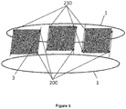
- front clamp (200) and at least one rear clamp (210) because, as for example represented on the figure 5 it is possible to have a pair of front grippers (200) and a pair of rear grippers (210), but it is possible to have only one front gripper and one rear gripper.
- front gripping means gripping at least one part situated at the front and secondly to rear gripping means gripping at least one part situated at the rear (which it is a front / rear edge or a side edge located at the front / rear).
- the front and rear gripping means can in fact each grab a substrate, respectively front and rear, that is to say a first substrate (called “before”) presenting itself first on the transport path and a second substrate (called “back”) which follows the first and may have a size different from the first.
- a single front gripper grasps a first substrate, said before, for example at its front edge or a side edge, while a single rear gripper grasps a second substrate, said back, for example at the level of its front edge or side edge. It is possible to also capture each of the front and rear substrates by at least two grippers which together form one of the front or rear gripping means,
- the substrate transport system (3) comprises means for detecting the speed and / or the position of the grippers (2) along the transport path, said detection means being controlled by the means computer (eg included in the printing machine).
- each clamp (2) may comprise a position sensor and / or a speed sensor connected to the computer means.
- said speed and / or position sensors are integrated with the motorization means, said motorization means being controlled by the computer means, and allowing the clamps (2) to move along the guides (1). ), themselves arranged along the transport path.
- the substrate transport system (3) includes substrate detecting means (generally for detecting the leading edge) when the latter enter the transport path, for example as soon as they leave the store. input.
- These means of detection, controlled by the computer means are for example and without limitation sensors included in at least one input store (30).
- this sensor is an optical encoder or an optical ruler.
- These detection means can detect, for example, the speed and / or the position of the substrates. Detection of the front edge may be sufficient insofar as the computer means know the speed of the substrates at the output of the input store, but it will also be possible to detect the speed to optimize the exploitation of this information by the computer means.
- the substrate transport system is therefore adapted, in certain embodiments, to detect the speed of the substrates (3) and to allow the clamps (2) moving along the guides (1) to grasp each substrate in such a way that to move it along the transport path oriented along the longitudinal axis.
- the substrate transport system (3) is also configured to tension the substrates (3), the tensioning force being applied by the grippers (2) holding the substrate at least along the longitudinal axis , so as to facilitate their transport and to increase the printing accuracy.
- the clamps (2) comprise a device for applying in a controlled manner a transverse voltage (ie, perpendicular to the longitudinal axis of the transport path) to the substrate, for example at the level of the transmission system. opening / closing (22) to apply the tension at the time of closure of the clamps.
- a transverse tensioning device may for example and without limitation include transversely extending suction pads just before closing said clamps (2) on the substrate (3).
- the applied voltage is parameterized using computer means as a function of the elasticity of the substrate and its width.
- a longitudinal tension ie, parallel to the longitudinal axis of the transport path
- a longitudinal tension is applied to the substrate, as detailed below.
- the substrate transport system (3) comprises at least one guide (1) on which a plurality of gripping means (2) and at least one drive means for moving the gripping means (2) (or grippers) are installed.
- the gripping means in particular front and rear, may in fact comprise a single gripper, to grasp the substrates on a single edge.
- the substrates are preferably grasped by their front edge, but it is also possible to seize them by a lateral edge, in particular in the case of sufficiently rigid substrates (possibly with respect to their size) in order to be required of the so.
- the movement of the grippers (2) is controlled in pairs, each of the grippers of each pair being generally disposed at the same level along the longitudinal axis (since the substrates are generally rectangular).
- each clamp (2) is connected to the other clamp of the pair located on the other side of the longitudinal axis of the transport path of the substrates (3).
- the substrate transport system (3) is adapted to capture each substrate so as to tension and / or move substrates (3) of variable sizes (in particular of variable length) along the transport path.
- the transport system comprises at least one motorization means (for example controlled by the computer means, in particular according to the substrates to be printed) ensuring a displacement of the gripping means (2) along the guide means (1). , with an independent movement between at least the front gripping means (2) and the rear gripping means (2).
- the front and rear gripping means each grip a substrate, respectively front and rear, as explained above (by a single clamp each for example), the substrates thus held, without longitudinal tension, can be moved in the machine of printing and the independent movement of the front and rear gripping means makes it possible to move substrates of variable sizes (which is therefore an example of the alternative of moving, without necessarily straining, substrates of variable sizes).
- said at least one motorization means comprises motor means equipping the gripping means (2).
- a motor can equip the clamps (2), individually or in pairs, to move the clamps along the guide means.
- each gripping means (2) comprises at least one motor means ensuring its displacement along the guide means (1).
- said at least one motorization means comprises at least one passive part equipping the gripping means (2) and at least one active part equipping the guiding means (1).
- the passive part integrated in the clamps allows the displacement of the latter, for example controlled individually or in pairs, on the guide means which comprise the active part or, possibly, which are parallel to the active part.
- said active portion of the motorization means comprises at least one linear motor.
- said at least one linear motor is installed on at least one rail parallel to the guide means (1).
- the transport system comprises at least two guiding means (1) on which the gripping means (2) moves.
- the transport system comprises pairs of gripping means (2), each comprising two gripping means (2) located on the same side, front or rear, of the same substrate, the displacement of a pair of gripping means (2) being provided by the same motorization means, along at least one guide means (1).
- the substrate transport system (3) includes gripper motor means (2).
- the motorization of the clamps (2) is achieved by linear motors.
- two clips (2), whose coordinates along the longitudinal axis are substantially the same, and which are installed on guides (1) located on either side of the transport path, are connected to the same linear motor. It is obvious, in order not to subject the substrates (3) to shear forces that could induce their deformation or tearing, that the speed of the grippers (2) having gripped the same substrate (3) is synchronized.
- the linear motors are installed on at least one rail parallel to the guides (1) on which the clamps (2) are installed. In some embodiments, the linear motors are integrated with the guides (1). For example and without limitation, only the passive part of the linear motor is associated with at least one clamp (2), the active part being installed on each guide (1) or on a rail parallel to the guides (1), following the embodiments.
- a substrate support (3) adjustable in position along an axis perpendicular to the substrate (3) so as to optimize the distance of the substrate (3) to the printing heads of the machine from printing, is integrated within the printing machine between the shops input (30) and output (31). For example and without limitation a sole disposed along the transport path between the inlet (30) and outlet (31).
- the substrate support (3) is adjustable in a plane perpendicular to the substrates (3).
- the substrate support has a slightly curved profile so as to accentuate the longitudinal tensioning of the substrates (3) in a convoy.
- the substrate support (3) comprises a plurality of openings, for example and without limitation cavities, so as to avoid the lifting of the moving substrates along the transport path of the aerodynamic effects, well known to those skilled in the art such as the phenomenon of lubrication.
- the substrate support in order to adapt to the different widths of substrates used, is transversely adjustable,
- the computer means control the opening and closing of the clamps (2), evaluate the speed and / or the position of the moving elements, and finally deliver the control and control signals of the motorization means (for example the linear motor or motors).
- the motorization means for example the linear motor or motors.
- Another object of the invention is to propose a method of setting and transporting substrates (3) along a transport path, implemented by various embodiments of the substrate transport system (3). previously described.
- the different successive stages characterizing this process and its possible variants according to various embodiments will now be described, with reference to Figures 1 to 5 illustratively and non-limitatively.
- the printable substrate (3) passes successively through all the stations constituting the printing machine, from the input magazine (30) to the reception of the substrates in the output magazine (31).
- the machine comprises only one printing station, preferably with a drying station, or several printing stations or customization known per se.
- the computer means control the opening and closing of the gripping means (2), evaluate the moving speed of the movable elements, and deliver the control and control signals of the motorization means (for example the linear motors).
- the clamps (2) can grasp the substrates by the side edges.
- the closing steps of the clamps will preferably take place on the lateral edges of the substrates.
- the transverse distance between two guide means (1) located on either side of the longitudinal axis of the transport path is variable.
- the method may therefore comprise at least one step of adjusting this distance between the guide means, for example depending on the size of the substrates on the transport path.
- the method comprises a transverse tensioning step of the substrate (3), performed by means of transverse tension included in the gripping means (2) and controlled by the computer means. This step is generally carried out during or after the closure of the gripping means (2).
- the invention allows a longitudinal tensioning of the substrates, and this, advantageously, regardless of their size.
- the step of tensioning the substrate (3) between two consecutive gripping means (2) is performed by the computer means such that the motorization means or means associated with the gripping means (2) located furthest back from the direction of movement of the substrate (3) exert a force directed in the direction opposite to the direction of movement of the substrate (3), the intensity of the force being parameterized according to the physical characteristics of the substrate (3).
- the substrate transport system (3) comprises interposing gripping means located between the front and rear gripping means.
- the method comprises a repetition, for each of these intermediate gripping means, of steps (d, d ", e, g and g ') relating to the rear gripping means, in particular in certain modes.
- the substrate transport system comprises n pairs of gripping means (2) for each of the transported substrates, n being greater than or equal to 2, the pairs comprising at least one front pair and one back pair, and possibly n
- n being greater than or equal to 2
- the pairs comprising at least one front pair and one back pair, and possibly n
- the position at a given instant and the speed of said substrate (3) are measured by means of a sensor, for example installed within an input store (30), said sensor being able for example and without limitation an optical encoder detecting the transverse edge before substrates (30) emerging from a magazine (30), the front term being defined with respect to the direction of movement of the substrates (3).
- This positron and speed information is sent to the computing means which in response controls the signal actuating at least one linear motor.
- the linear motor will thus allow the movement of a first pair of clamps (2), said clamps being located on either side of the transport path of the substrates (3) and having substantially equal longitudinal coordinates, in order to position said pair of clamps (2) in an area near an input magazine (30), said area being called an entry zone (ZE).
- ZE entry zone
- a portion of the substrate (3) is considered to be in the input zone (ZE) as long as less than two pairs of grippers (2) have grasped the longitudinal edges of said substrate portion ( 3). In this input area, no printing is planned.
- the first pair of pincers (2) positioned in the preceding step adopts a synchronized movement at a speed adapted to that of the substrate (3) leaving the input magazine (30), positioning in an area of the longitudinal edge near the front portion of the substrate (3).
- each clamp (2) of the first pair grips a front corner of the substrate (3).
- the positioning and the speed of the pair of clamps (2) are adapted according to the information of speed and position of the substrate (3) recorded by the computer means. Said computer means exploit this speed and position information of the substrate (3) to control the speeds and the synchronization of the clamps (2) as a function of the position of the substrate along the transport path.
- the speed of the first pair of clips (2) synchronizes with the substrate speed (3) and is positioned at the front corners of said substrate (3). In other embodiments, the speed of the substrate (3) once output from the input store is zero, the motorization of the first pair of clamps (2) positioning the latter at the front corners of the substrate, before stop.
- the opening / closing system (22) of each clamp (2) of the first pair is actuated by the computer means. This results in the closing of the first pair of pliers (2) on the longitudinal edges of the substrate (3), said substrate now being driven by the clamps (2).
- a second pair of clamps (2) each clamp being located on either side of the transport path and having substantially equal longitudinal coordinates, is positioned in the input zone ( ZE) by actuation of the linear motor by computer means.
- the speed of the second pair of clamps (2) is then adapted to the speed of the first pair of clamps (2), the second pair of clamps (2) being positioned in an area near the longitudinal edges of said substrate (3) , excluding at least the front corners, so that the opening / closing mechanism (22) actuates the moving parts (21) said grippers (2) so as to grip the substrate (3) on the longitudinal edges of the substrate (3). From the moment when at least two pairs of clamps (2) have gripped the substrate (3) so as to ensure the convoy, the substrate (3) enters the printing zone (ZI), and the substrate portions (3) included between the clamps (2) can be subjected to printing any pattern.
- the substrate portion (3) between the two pairs of clamps (2) having gripped said substrate (3) is mechanically tensioned.
- this step of tensioning the substrate (3) between two consecutive pairs of clamps (2) is performed as follows: the computer means sends a signal to the engine of the pair of clamps (2) located the furthest back from the direction of movement of the substrate (3), so that a decrease in the speed noted ⁇ v is applied to the (x) motor (s) of the pair of the forceps (2) the rearmost .
- the speed of the two pairs of clamps (2) is synchronized again by a signal sent by the computer means to the motors of said pairs of clamps (2).
- the step of tensioning the substrate between two consecutive pairs of clamps (2) is performed in the following manner: the computer means send a signal to the motor (s) of the pair of tongs (2) located furthest from the direction of movement of the substrate (3), so that the motor (s) of said pair of tongs (2) exert a longitudinal force directed in the direction opposed to the direction of displacement of the substrate (3), the intensity of the force being parameterized using the computer means according to the physical characteristics of the substrate (3).
- force sensors included in the clamps (2) can measure the voltage force existing at the gripping area of the substrate (2). So when the force measured reaches the threshold defined for the substrate (3) in question, the computer means send to the motors ensuring the movement of the clamps (2) along the guides (1) a speed synchronization signal.
- the fourth and fifth steps (d and e) are repeated for the n-2 pairs of clamps (2) remaining.
- the pairs of clamps (2) are equidistant, and the last pair of clamps (2), located furthest back from the direction of movement of the substrate (3), is positioned in an area of the longitudinal edge of the substrate (3) close to the rear part of the substrate (3).
- the last pair of clamps (2) captures the rear corners of the substrate (3).
- the convoy and the tensioning of the substrate (3) are thus ensured by the n pairs of clamps (2) having grasped the longitudinal edges of said substrate (3) and motorized on the guides (1) arranged on either side of the transport way.
- the computer means send a signal to the system of opening / closing (22) of the first pair of forceps (2), located furthest forward with respect to the direction of movement of the substrate (3), so that said opening / closing system (22) actuates the movement of the mobile part (21) of the clamps (2) of the first pair, thus releasing the substrate (3), for example and without limitation at the front corners.
- This part of the substrate (3), between the freed front transverse edge and the next pair of clamps (2) still gripping the substrate, is now located in an area called exit zone (ZS).
- Part of the substrate (3) is in an exit zone (ZS) when there is a maximum of a pair of clamps (2) gripping the substrate portion (3) at the longitudinal edges.
- this output area (ZS) no printing is provided.
- the motor controlling the latter pair slowed down until said pair of clamps (2) stop in an area close to an outlet magazine (31).
- the computer means send, after a time t 1 depending on the speed and / or the length of the substrate (3), a signal to the opening / closing system (22) of the pair of pliers (2) located just behind the first pair of forceps (2) located furthest forward, so that said opening / closing system (22) actuates the movement of the movable part (21) of the tongs (2) of the second pair.
- the computer means then send a signal to the motor (s) of the second pair of clamps (2) so that the latter slows down, thus releasing the substrate (3).
- This eighth step is repeated for the following n-2 pairs of clamps (2), up to the last pair situated furthest behind the substrate (3) with respect to the direction of movement, for example and in a nonlimiting manner at the rear corners of the substrate (3).
- the computer means send to the motors n pairs of clamps (2) a return signal clamps (2) in a storage area of the guides (1), near a store area input (30), the motors stopping when the position detecting means detect that the clamps (2) are present in this storage area.
- the method of tensioning and transporting substrates is applicable to a substrate transport system comprising guides (1) forming closed circuits.
- the steps g to i described above are replaced by the following steps.
- a seventh alternative step when the substrate (3) in convoy through the guides (1) and the clamps (2) arrive near an outlet store (31), the computer means send a signal to the system opening / closing (22) of the first pair of grippers (2), located most before the direction of movement of the substrate (3), so that said opening / closing system (22) actuates the displacement of the movable portion (21) of the tongs (2) of the first pair, thereby releasing the substrate ( 3), for example and without limitation at the front corners.
- This part of the substrate, between the freed front transverse edge and the next pair of gripper still grasping the substrate (3), is now located in the exit zone (ZS).
- the motor controlling the latter accelerates the pair of clamps (2), so that the pair of clamps (2) continues its movement along the guides (1). and returns to a storage area near an input store (30).
- the guides (1) are in a plane parallel to the plane of the substrate (3), then the clamps deviate from the substrate (3) in a plane parallel to said substrate (3), just after the tongs (2) have released the substrate.
- the computing means send at the end of a time t 2 depending on the speed and / or the length of the substrate (3), a signal to the opening / closing system (22) of the pair of clamps (2) located just behind the first pair of forceps (2) located furthest forward, so that said opening / closing system (22) actuates the movement of the movable part of the clamps (2) of the second pair.
- the computer means then sends a signal to the motor (s) of the second pair of clamps (2) so that the latter slows down, thus releasing the substrate (3), then an acceleration signal from the pair of clamps ( 2) is sent to the motors via the computer means, so that said pair of clamps (2) continues its movement along the guides (1) and returns to a storage area near an input store (30). ).
- the first six steps of the method (a-f) are replaced by the following steps.
- n pairs of clamps (2) are positioned in the entry zone (ZE) along the guides, the clamps (2) of the same pair being installed on each side and another of the transport path, the clamps (2) being positioned following detection by the detection means of the speed and the position of the substrate (3) leaving an input magazine (30), for example and of non-limiting way the detection of the front transverse edge of the substrate (3).
- the n pairs of clamps (2) positioned in the preceding step adopt a synchronized movement at a speed adapted to that of the substrate (3) coming out of the input magazine (30).
- the positioning and the speed of the pairs of clamps (2) are adapted according to the information of speed and position of the substrate (3) recorded by the computer means.
- Said computer means exploit this speed and position information of the substrate (3) to control the speeds and the synchronization of the clamps (2) as a function of the position of the substrate (3) along the transport path.
- the speed of the substrate (3) once output from the input store is zero, the motorization of the n pairs of clamps (2) adapting accordingly.
- n-1 substrate parts (3) between the n pairs of clamps (2) are mechanically tensioned.
- each pair of clamps (2) is substituted by a single clamp (2) adapted to grip the substrate (3), by example over all or part of the width of the lateral edge of the substrate (3).
- the method of transporting and tensioning the substrate (3) can be carried out using two clamps (2) per substrate (3), each gripping a lateral edge of the substrate.
- the positioning of the clamps (2), the adaptation of the speed of the clamps (2) to that of the substrate (3), the gripping of the lateral edges of the substrate (3), the tensioning of the substrate (3), the release of the substrate (3) and the return of the clamps (2) in the storage area can then be performed according to the method described above.
Description
La présente invention se rapporte au domaine de l'impression, en particulier sans contact avec les substrats, et plus particulièrement à un dispositif et un procédé permettant de transporter des substrats imprimables sur l'ensemble des postes de travail compris dans une machine d'impression, le transport des substrats étant réalisé de manière à permettre leur impression dans des conditions optimales.The present invention relates to the field of printing, in particular without contact with the substrates, and more particularly to a device and a method for transporting printable substrates on all the workstations included in a printing machine. the substrates are transported in such a way as to allow their printing under optimal conditions.
Il est connu de l'art antérieur, des transports de substrats imprimables réalisés par des courroies d'aspiration, qui ont pour fonction de maintenir et tendre un substrat contre lesdites courroies en déplacement. Ce type de solution, bien connue de l'homme du métier, présente néanmoins quelques inconvénients. En particulier, ce type de dispositif, occasionnant des mouvements d'air et des gradients de pression, peut provoquer la déformation des substrats si ces derniers sont de taille importante. La précision de l'impression s'en trouvera donc affectée. D'autre part, l'utilisation de ces courroies d'aspiration avec certaines technologies d'impression très répandues, notamment l'impression jet d'encre, peut occasionner une aspiration accidentelle de l'encre présente dans les têtes d'impression et ainsi provoquer le désamorçage des têtes d'impression. Ce genre d'incident nécessite dans le meilleur des cas un réamorçage des têtes, et dans le pire des cas un remplacement des têtes désamorcées, devenues de fait inutilisables si ces dernières sont solidaires du réservoir d'encre.It is known from the prior art, transportable printable substrates made by suction belts, whose function is to maintain and tension a substrate against said moving belts. This type of solution, well known to those skilled in the art, nevertheless has some disadvantages. In particular, this type of device, causing air movements and pressure gradients, can cause the deformation of the substrates if they are large. The accuracy of printing will therefore be affected. On the other hand, the use of these suction belts with some widely used printing technologies, such as inkjet printing, can cause accidental suctioning of the ink in the print heads and defuse the printheads. This type of incident requires in the best case a reboot of the heads, and in the worst case a replacement of defused heads, become unusable if they are secured to the ink tank.
Pour palier ces problèmes, notamment permettre le déplacement de substrats de manière précise, il existe dans l'art antérieur des techniques utilisant des cylindres comportant une pluralité de pinces saisissant les substrats par le bord avant par rapport au sens de déplacement du substrat. Adapté à des machines d'impression de type jet d'encre, ce type de solution présente néanmoins plusieurs inconvénients. En effet, ce système nécessite un arrangement de toutes les têtes jet d'encre de façon orbitale autour d'un cylindre de grande dimension. De plus, ce type de système pose le problème de la difficulté du réglage de la position des têtes d'impression. En effet, pour une impression de qualité, l'encre éjectée des têtes d'impression doit former un jet dont la direction est perpendiculaire à la surface du substrat. On comprend dans ce cas que l'utilisation d'un cylindre pour transporter et tendre le substrat, dont la surface n'est par définition pas plane, impose des réglages fastidieux de la position des têtes d'impression. Pour cette même raison, il est difficile d'utiliser des substrats d'épaisseur variable, le changement de substrat imposant un réglage de toutes les têtes d'impression. D'autre part, le pas d'impression, c'est-à-dire la position des pinces sur le cylindre, est fixe, ce qui signifie que la cadence d'impression reste la même quelque soit la taille du substrat.To overcome these problems, in particular to allow the displacement of substrates accurately, there are in the prior art techniques using cylinders having a plurality of grippers gripping the substrates by the leading edge relative to the direction of movement of the substrate. Suitable for inkjet type printing machines, this type of solution nevertheless has several disadvantages. Indeed, this system requires an arrangement of all orbital inkjet heads around a large cylinder. In addition, this type of system raises the problem of the difficulty of adjusting the position of the printheads. Indeed, for a quality printing, the ink ejected from the print heads must form a jet whose direction is perpendicular to the surface of the substrate. It is understood in this case that the use of a cylinder for transporting and tensioning the substrate, whose surface is by definition not flat, imposes tedious adjustments of the position of the printing heads. For the same reason, it is difficult to use substrates of variable thickness, the change of substrate imposing an adjustment of all the print heads. On the other hand, the printing pitch, that is to say the position of the clamps on the cylinder, is fixed, which means that the print rate remains the same regardless of the size of the substrate.
Il est également connu de l'art antérieur des systèmes de transport de substrat utilisant des chaines ou convoyeurs sur lesquels sont disposés des pinces pour saisir les substrats et les transporter sur un chemin de transport dont une portion est plane, ce qui résout le problème de l'agencement des têtes d'impression, voir le document
La présente invention a pour objet de résoudre au moins un des problèmes de l'art antérieur, tels qu'exposés ci-dessus. L'invention propose un nouveau dispositif et un nouveau procédé permettant de transporter des substrats imprimables de manière précise, adapté à des substrats de divers types, tailles et épaisseurs. En particulier, l'invention permet de réaliser des impressions à pas variable. En outre, l'invention est adaptée aux machines d'impression sans contact avec le substrat, comme les machines d'impression jet d'encre.The present invention aims to solve at least one of the problems of the prior art, as outlined above. The invention proposes a new device and a novel method for transporting printable substrates accurately, suitable for substrates of various types, sizes and thicknesses. In particular, the invention makes it possible to produce variable pitch prints. In addition, the invention is adapted to machines non-contact printing with the substrate, such as inkjet printing machines.
A cet effet, l'invention concerne une machine d'impression comprenant un système de transport de substrats telle que définie dans la revendication 1. D'autres particularités et avantages du système de transport de substrats sont détaillés dans la présente demande. Un objectif supplémentaire de l'invention est de proposer un procédé de transport et de mise en tension de substrats imprimables.To this end, the invention relates to a printing machine comprising a substrate transport system as defined in
A cet effet, l'invention concerne un procédé de mise en tension et de transport de substrats le long d'un chemin de transport, mis en oeuvre par un système de transport de substrats selon l'invention, telle que défini dans la revendication 22. D'autres particularité et avantages du procédé de mise en tension et de transport de substrats sont détaillés dans la présente demande.To this end, the invention relates to a method for the stressing and transport of substrates along a transport path, implemented by a substrate transport system according to the invention, as defined in
L'invention, avec ses caractéristiques et avantages, ressortira plus clairement à la lecture de la description faite en référence aux dessins annexés dans lesquels :
- La
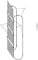
figure 1 illustre de manière schématique une vue tridimensionnelle du système de transport de substrats selon certains modes de réalisation. - La
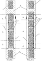
figure 2 illustre de manière schématique un premier mode de réalisation de l'invention. - La
figure 3 illustre de manière schématique un deuxième mode de réalisation de l'invention. - La
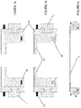
figure 4a illustre une paire de moyen de préhension en position ouverte, la partie mobile assurant l'ouverture étant en vis-à-vis du verso du substrat, le recto étant la face imprimable en vis-à-vis des têtes d'impression. - La
figure 4b illustre une paire de moyen de préhension en position fermée, la partie mobile assurant l'ouverture étant en vis-à-vis du verso du substrat, le recto étant la face imprimable en vis-à-vis des têtes d'impression. - La
figure 4c illustre une paire de moyens de préhension maintenant un substrat par ses bords latéraux. - La
figure 5 illustre de manière schématique un troisième mode de réalisation de l'invention.
- The
figure 1 schematically illustrates a three-dimensional view of the substrate transport system according to some embodiments. - The
figure 2 schematically illustrates a first embodiment of the invention. - The
figure 3 schematically illustrates a second embodiment of the invention. - The
figure 4a illustrates a pair of gripping means in the open position, the movable portion providing the opening being opposite the back of the substrate, the front being the printable face vis-à-vis the printing heads. - The
figure 4b illustrates a pair of gripping means in closed position, the movable portion providing the opening being vis-à-vis the back of the substrate, the front being the printable face vis-à-vis the printheads. - The
figure 4c illustrates a pair of gripping means holding a substrate by its side edges. - The
figure 5 schematically illustrates a third embodiment of the invention.
La présente invention concerne un dispositif ou système (les deux termes étant ici utilisés indifféremment) de transport de substrats, ainsi qu'un procédé de transport et de mise en tension de substrats. Le système de transport de substrats est décrit ci-dessous en référence aux figures, mais il est clair que les figures et les exemples fournis dans la présente demande sont illustratifs et non limitatifs. Ledit système de transport de substrats est compris dans une machine d'impression, par exemple et de façon non limitative une machine d'impression jet d'encre. La machine est contrôlée par des moyens informatiques qui commandent notamment les différents postes de travail, en contrôlant, d'après des paramètres de configuration (dépendant notamment des substrats), leurs dispositifs, systèmes ou moyens (motorisation, préhension, guidage, détection). Les moyens informatiques peuvent également collecter les informations de différents moyens de détection (capteurs par exemple) pour coordonner les opérations des divers postes, dispositifs, systèmes et moyens de la machine. Ces moyens informatiques n'ont pas à être détaillés dans la présente demande et ils pourront par exemple être intégrés à la machine ou déportés dans un dispositif ou système séparé. Les capteurs donnent par exemple, des informations de positions des substrats, des informations de configurations des substrats (3) et/ou des informations de validation suite à une opération correctement effectuée ou non. Certaines informations nécessaires à la mise en oeuvre de l'invention peuvent également être enregistrées au préalable dans les moyens informatiques (par exemple via une saisie sur une interface par un opérateur). De telles informations peuvent par exemple concerner la taille des substrats ou leur épaisseur, mais il est généralement préféré que des capteurs mesurent ou vérifient de telles informations. Les substrats (3) en attente d'impression sont généralement, de façon connue en soi, placés dans au moins un magasin d'entrée (30) ayant une capacité définie en fonction de la nature du substrat (3) et des besoins pour l'impression. Dans un exemple de réalisation, un magasin d'entrée (30) est prévu pour accepter plusieurs milliers de substrats (3) de nature, d'épaisseur et de dimension variable (par exemple et de façon non limitative d'un format carte de crédit jusqu'au format A0). Une fois le processus d'impression terminé, les substrats (3) sont stockés dans au moins un magasin de sortie (31) ayant généralement la même capacité qu'un magasin d'entrée. Un dispositif de saisie des substrats (3) permet de sortir les substrats (3) du magasin d'entrée (30) et de les disposer sur des moyens d'entraînement, par exemple le système de transport des substrats dont les caractéristiques seront détaillées plus loin dans la description, pour les déplacer le long d'une chaîne de travail comportant généralement plusieurs postes de travail, par exemple et de façon non limitative au moins un poste d'impression comprenant une pluralité de têtes d'impression jet d'encre contrôlées par les moyens informatiques, suivi d'un poste de séchage. En général, des contrôles sont également effectués afin de détecter la présence d'un substrat (3) unique à chaque poste du convoyeur. La machine d'impression permet de réaliser des impressions d'un substrat à l'autre avec un pas variable, grâce au système de transport, comme détaillé ci-après. Cela signifie que la machine d'impression est en mesure d'adapter l'utilisation des têtes d'impression et la vitesse de transport des substrats (3) en fonction de la taille des substrats (3), par exemple grâce à des capteurs installés sur la machine d'impression. Dans certains modes de réalisation, la machine d'impression est équipée d'un dispositif de retournement des substrats (3), autorisant l'impression recto-verso desdits substrats.The present invention relates to a device or system (here both terms being used interchangeably) for transporting substrates, as well as a method for transporting and tensioning substrates. The substrate transport system is described below with reference to the figures, but it is clear that the figures and examples provided in this application are illustrative and not limiting. Said substrate transport system is included in a printing machine, for example and without limitation an inkjet printing machine. The machine is controlled by computer means which control in particular the various workstations, by controlling, according to configuration parameters (particularly dependent on substrates), their devices, systems or means (motorization, gripping, guiding, detection). The computer means can also collect information from different detection means (sensors for example) to coordinate the operations of the various stations, devices, systems and means of the machine. These computer means do not have to be detailed in the present application and they may for example be integrated in the machine or deported in a device or separate system. The sensors give, for example, position information of the substrates, configuration information of the substrates (3) and / or validation information following a correctly performed operation or not. Some information necessary for the implementation of the invention can also be registered beforehand in the computer means (for example via input on an interface by an operator). Such information may for example relate to the size of the substrates or their thickness, but it is generally preferred that sensors measure or verify such information. The substrates (3) awaiting printing are generally, in a manner known per se, placed in at least one input magazine (30) having a capacity defined according to the nature of the substrate (3) and the needs for the 'impression. In an exemplary embodiment, an input store (30) is provided to accept several thousand substrates (3) of nature, thickness and variable size (for example and without limitation a credit card format up to A0). Once the printing process is complete, the substrates (3) are stored in at least one output store (31) generally having the same capacity as an input store. A substrate gripping device (3) makes it possible to release the substrates (3) from the input magazine (30) and to arrange them on drive means, for example the substrates transport system, the characteristics of which will be detailed in more detail. far in the description, to move them along a working line generally comprising several workstations, for example and without limitation at least one printing station comprising a plurality of controlled inkjet printheads by computer means, followed by a drying station. In general, controls are also performed to detect the presence of a single substrate (3) at each post of the conveyor. The printing machine makes it possible to print from one substrate to another with a variable pitch, thanks to the transport system, as detailed below. This means that the printing machine is able to adapt the use of the print heads and the transport speed of the substrates (3) according to the size of the substrates (3), for example by means of sensors installed on the printing machine. In some embodiments, the printing machine is equipped with a substrate reversing device (3), allowing two-sided printing of said substrates.
Dans certains modes de réalisation, et en référence illustrative et non limitative aux
Dans la présente description, les substrats, les pinces ou les bords des substrats qui sont situés vers le magasin de sortie sont désignés par le terme « avant », tandis que ceux situés vers le magasin d'entrée sont désignés par le terme « arrière », en référence au sens de déplacement des substrats dans la machine d'impression. D'autre part, on désigne par le terme « latéral », les éléments se trouvant de part et d'autre de l'axe longitudinal du chemin de transport. Enfin, on désigne par le terme « intercalaire » les pinces saisissant un substrat à un niveau situé entre l'avant et l'arrière de ce substrat (donc entre les pinces avant et arrière). On comprend que ces désignations sont conventionnelles et ne sont pas limitatives. Dans certains modes de réalisation, les pinces (2) contrôlées par les moyens informatiques saisissent chaque substrat (3) dans une zone proche des quatre coins du substrat. Néanmoins, selon la configuration (notamment le contrôle effectué par les moyens informatiques), diverses pinces peuvent saisir les substrats en différents endroits, notamment sur les bords avant et/ou arrière et/ou sur les bords latéraux.In the present description, the substrates, clips or edges of the substrates that are located towards the outlet store are referred to as "front", while those located to the entrance store are referred to as "back". , with reference to the direction of movement of the substrates in the printing machine. On the other hand, the term "lateral" refers to the elements lying on either side of the longitudinal axis of the transport path. Finally, the term "interlayer" refers to grippers gripping a substrate at a level located between the front and the rear of this substrate (thus between the front and rear clamps). It is understood that these designations are conventional and are not limiting. In some embodiments, the forceps (2) controlled by the computer means grip each substrate (3) in an area near the four corners of the substrate. Nevertheless, depending on the configuration (in particular the control carried out by the computer means), various clamps can grip the substrates in different places, in particular on the front and / or rear edges and / or on the lateral edges.
Dans certains modes de réalisation, la partie mobile (21) de chaque pince (2) est située en vis-à-vis du recto de chaque substrat (3), le recto étant la face imprimable des substrats (3) située en vis-à-vis des têtes d'impression. Ces modes de réalisation permettent en général de faciliter la libération des substrats, notamment lorsque les pinces s'éloignent du substrat en direction de la face verso lorsqu'elles ont libéré le substrat (par exemple dans le cas d'un convoyeur en circuit fermé). Dans d'autres modes de réalisation, généralement préférés, la partie mobile (21) des pinces est située en vis-à-vis du verso de chaque substrat (3) en convoi. Cet arrangement permet de limiter les risques de contact de la partie mobile avec les têtes d'impression. D'autre part, la position des têtes d'impression est généralement réglable au moins dans le sens de la hauteur (perpendiculairement au plan du chemin de transport), ce qui permet d'éviter tout contact entre la partie mobile (21) des pinces (2) et les têtes d'impression. Cette hauteur réglable est particulièrement avantageuse dans les modes de réalisation où la partie mobile est du côté recto et dans les modes où les parties mobiles sont à la fois du côté recto et du côté verso. Enfin, le système d'ouverture/fermeture (22) des pinces est par exemple contrôlé par un électroaimant, ou un système de tringles.In some embodiments, the movable portion (21) of each gripper (2) is located vis-à-vis the front of each substrate (3), the front being the printable face of the substrates (3) located vis-à-vis the to the print heads. These embodiments generally make it possible to facilitate the release of the substrates, in particular when the clamps move away from the substrate in the direction of the back side when they have released the substrate (for example in the case of a substrate). closed circuit conveyor). In other embodiments, generally preferred, the movable portion (21) of the clamps is located vis-à-vis the back of each substrate (3) convoy. This arrangement makes it possible to limit the risks of contact of the moving part with the print heads. On the other hand, the position of the printheads is generally adjustable at least in the direction of the height (perpendicular to the plane of the transport path), which makes it possible to avoid any contact between the movable part (21) of the clamps. (2) and the print heads. This adjustable height is particularly advantageous in the embodiments where the moving part is on the front side and in the modes where the moving parts are both the front side and the back side. Finally, the opening / closing system (22) of the clamps is for example controlled by an electromagnet, or a system of rods.
Dans certains modes de réalisation, le système de transport de substrats comprend des moyens de guidage (1) des pinces (2), disposés sur toute la longueur du chemin de transport des substrats (3). Par abus de langage, on peut désigner de tels moyens de guidage sous le terme de moyens de déplacement de pinces motorisés, mais on préfère ici la désignation de guidage, notamment parce que les pinces peuvent comporter une motorisation ou seulement une partie passive de motorisation. Par exemple et de façon non limitative, ces moyens de guidage (1) des pinces sont des guides, des rails ou glissières, disposés le long du chemin de transport des substrats (3). Dans certains modes de réalisation, les moyens de guidage forment un circuit fermé dont une partie « aller » forme le chemin de transport et une partie « retour » forme un chemin de retour des pinces vers le magasin d'entrée. Le terme « guide » est utilisé dans la présente description pour désigner les moyens de guidage (1) de manière illustrative et non limitative. Dans certains modes de réalisation chaque guide (1) de déplacement forme un circuit fermé pouvant être par exemple de forme oblongue, chaque guide (1) étant dans un plan parallèle au plan des substrats (i.e., du chemin de transport). Dans des modes de réalisation alternatifs, chaque guide est dans un plan perpendiculaire au plan des substrats (3).In some embodiments, the substrate transport system includes guide means (1) for the grippers (2) disposed along the entire length of the transport path of the substrates (3). By abuse of language, such guide means can be referred to as means for moving motorized grippers, but here the guide designation is preferred, in particular because the grippers may comprise a motor or only a passive motorization part. For example and without limitation, these guide means (1) of the clamps are guides, rails or slides, arranged along the substrate transport path (3). In some embodiments, the guiding means forms a closed circuit of which a "go" part forms the transport path and a "return" portion forms a return path of the clamps to the input magazine. The term "guide" is used in the present description to denote the guide means (1) in an illustrative and non-limiting manner. In some embodiments, each displacement guide (1) forms a closed circuit that may be, for example, oblong, each guide (1) being in a plane parallel to the plane of the substrates (ie, of the transport path). In alternative embodiments, each guide is in a plane perpendicular to the plane of the substrates (3).
Dans certains modes de réalisation préférentiels, le système de transport des substrats (3) comprend deux guides (1) comprenant une pluralité de pinces (2), chaque guide (1) étant disposé de part et d'autre du chemin de transport des substrats (3). Dans certains de ces modes de réalisation, le système de transport de substrats peut comporter une pluralité de guides (1) disposés en paire, de part et d'autre du chemin de transport, la distance entre les guides (1) de chaque paire étant différente pour permettre une adaptation du système de transport de substrats (3) à des substrats (3) de taille différente, en particulier de largeur variable. Dans certains modes de réalisation préférentiels, le système de transport de substrats (3) comprend deux guides (1) disposés de part et d'autre du chemin de transport des substrats (2), dont l'écartement transversal est variable et contrôlé par les moyens informatiques, le système de transport de substrats (3) pouvant ainsi s'adapter à toute taille de substrat (3). Dans certains modes de réalisation, dont un exemple non limitatif est illustré de manière schématique sur la
La présente demande définit des moyens de préhension avant et des moyens de préhension arrière. On parle ici d'au moins une pince avant (200) et au moins une pince arrière (210) car, comme par exemple représenté sur la
Dans certains modes de réalisation, le système de transport des substrats (3) comprend des moyens de détection de la vitesse et/ou de la position des pinces (2) le long du chemin de transport, lesdits moyens de détection étant contrôlés par les moyens informatiques (par exemple compris dans la machine d'impression). Par exemple et de façon non limitative, chaque pince (2) peut comprendre un capteur de position et/ou un capteur de vitesse relié(s) aux moyens informatiques. Dans des modes de réalisation préférentiels, lesdits capteurs de vitesse et/ou de position sont intégrés aux moyens de motorisation, lesdits moyens de motorisation étant contrôlés par les moyens informatiques, et permettant aux pinces (2) de se mouvoir le long des guides (1), eux-mêmes disposés le long du chemin de transport.In some embodiments, the substrate transport system (3) comprises means for detecting the speed and / or the position of the grippers (2) along the transport path, said detection means being controlled by the means computer (eg included in the printing machine). For example and without limitation, each clamp (2) may comprise a position sensor and / or a speed sensor connected to the computer means. In preferred embodiments, said speed and / or position sensors are integrated with the motorization means, said motorization means being controlled by the computer means, and allowing the clamps (2) to move along the guides (1). ), themselves arranged along the transport path.
Dans certains modes de réalisation, le système de transport des substrats (3) comprend des moyens de détection des substrats (généralement pour la détection du bord avant) lorsque ces derniers entrent sur le chemin de transport, par exemple dès qu'ils sortent du magasin d'entrée. Ces moyens de détection, contrôlés par les moyens informatiques, sont par exemple et de façon non limitative des capteurs compris dans au moins un magasin d'entrée (30). Par exemple et de façon non limitative, ce capteur est un codeur optique ou une règle optique. Ces moyens de détection peuvent détecter par exemple la vitesse et/ou la position des substrats. La détection du bord avant peut suffire dans la mesure où les moyens informatiques connaissent la vitesse des substrats en sortie du magasin d'entrée, mais on pourra également détecter la vitesse pour optimiser l'exploitation de ces informations par les moyens informatiques. Ainsi, le système de transport de substrats est donc adapté, dans certains modes de réalisation, pour détecter la vitesse des substrats (3) et permettre aux pinces (2) se déplaçant le long des guides (1), de saisir chaque substrat de manière à le déplacer le long du chemin de transport orienté selon l'axe longitudinal.In some embodiments, the substrate transport system (3) includes substrate detecting means (generally for detecting the leading edge) when the latter enter the transport path, for example as soon as they leave the store. input. These means of detection, controlled by the computer means, are for example and without limitation sensors included in at least one input store (30). For example and without limitation, this sensor is an optical encoder or an optical ruler. These detection means can detect, for example, the speed and / or the position of the substrates. Detection of the front edge may be sufficient insofar as the computer means know the speed of the substrates at the output of the input store, but it will also be possible to detect the speed to optimize the exploitation of this information by the computer means. Thus, the substrate transport system is therefore adapted, in certain embodiments, to detect the speed of the substrates (3) and to allow the clamps (2) moving along the guides (1) to grasp each substrate in such a way that to move it along the transport path oriented along the longitudinal axis.
Dans certains modes de réalisation, le système de transport de substrats (3) est également configuré pour mettre en tension les substrats (3), la force de tension étant appliquée par les pinces (2) retenant le substrat au moins suivant l'axe longitudinal, de manière à faciliter leur transport et à augmenter la précision d'impression. Par exemple et de façon non limitative, les pinces (2) comportent un dispositif permettant d'appliquer de façon contrôlée une tension transversale (i.e., perpendiculairement à l'axe longitudinal du chemin de transport) au substrat, par exemple au niveau du système d'ouverture/fermeture (22) pour appliquer la tension au moment de la fermeture des pinces. Un tel dispositif de mise en tension transversale peut par exemple et de façon non limitative comporter des patins aspirants s'écartant transversalement juste avant la fermeture desdites pinces (2) sur le substrat (3). La tension appliquée est paramétrée à l'aide des moyens informatiques en fonction de l'élasticité du substrat et de sa largeur. Dans certains modes de réalisation non exclusifs de ceux à tension transversale ci-dessus, une tension longitudinale (i.e., parallèlement à l'axe longitudinal du chemin de transport) est appliquée au substrat, comme détaillé ci-après.In some embodiments, the substrate transport system (3) is also configured to tension the substrates (3), the tensioning force being applied by the grippers (2) holding the substrate at least along the longitudinal axis , so as to facilitate their transport and to increase the printing accuracy. For example and in a nonlimiting manner, the clamps (2) comprise a device for applying in a controlled manner a transverse voltage (ie, perpendicular to the longitudinal axis of the transport path) to the substrate, for example at the level of the transmission system. opening / closing (22) to apply the tension at the time of closure of the clamps. Such a transverse tensioning device may for example and without limitation include transversely extending suction pads just before closing said clamps (2) on the substrate (3). The applied voltage is parameterized using computer means as a function of the elasticity of the substrate and its width. In some embodiments not exclusive of those with transverse voltage above, a longitudinal tension (ie, parallel to the longitudinal axis of the transport path) is applied to the substrate, as detailed below.
Le système de transport des substrats (3) comprend au moins un guide (1) sur lequel est installée une pluralité des moyens de préhension (2) et au moins un moyen de motorisation pour le déplacement des moyens de préhension (2) (ou pinces). Comme mentionné plus haut, les moyens de préhension, notamment avant et arrière, peuvent comporter en fait une seule pince, pour saisir les substrats sur un seul bord. Dans ce cas, on saisit de préférence les substrats par leur bord avant, mais il est également possible éventuellement de les saisir par un bord latéral, notamment dans le cas de substrats suffisamment rigides (éventuellement par rapport à leur taille) pour être tenus de la sorte. Dans certains modes de réalisation, le déplacement des pinces (2) est contrôlé par paires, chacune des pinces de chaque paire étant généralement disposée au même niveau le long de l'axe longitudinal (puisque les substrats sont généralement rectangulaires). Dans certains de ces modes de réalisation, les pinces sont indépendantes mais leur déplacement est synchronisé par paire. Dans d'autres modes de réalisation, chaque pince (2) étant reliée à l'autre pince de la paire située de l'autre côté de l'axe longitudinal du chemin de transport des substrats (3). De préférence, le système de transport de substrats (3) est adapté pour saisir chaque substrat de manière à tendre et/ou déplacer des substrats (3) de tailles variables (notamment de longueur variable) le long du chemin de transport. En effet, le système de transport comporte au moins un moyen de motorisation (par exemple contrôlé par les moyens informatiques, notamment en fonction des substrats à imprimer) assurant un déplacement des moyens de préhension (2) le long des moyens de guidage (1), avec un déplacement indépendant entre au moins les moyens de préhension (2) avant et les moyens de préhension (2) arrière. Ainsi, en contrôlant la vitesse des pinces avant et arrière, il est possible de mettre en tension (longitudinale) les substrats quelles que soient leurs tailles (en longueur en l'occurrence, la tension en largeur étant gérée par le dispositif de tension transversale). De tels substrats tendus peuvent être déplacés sur le chemin de transport ou être maintenus immobiles, par exemple lors de l'impression avec des têtes d'impression mobiles ou lors d'un séchage (ce qui est donc un exemple de l'alternative de tendre, sans forcément déplacer). D'autre part, dans le cas où les moyens de préhension avant et arrière saisissent chacun un substrat, respectivement avant et arrière, comme expliqué précédemment (par une seule pince chacun par exemple), les substrats ainsi tenus, sans tension longitudinale, peuvent être déplacés dans la machine d'impression et le déplacement indépendant des moyens de préhension avant et arrière permet de déplacer des substrats de tailles variables (ce qui est donc un exemple de l'alternative de déplacer, sans forcément tendre, des substrats de tailles variables).The substrate transport system (3) comprises at least one guide (1) on which a plurality of gripping means (2) and at least one drive means for moving the gripping means (2) (or grippers) are installed. ). As mentioned above, the gripping means, in particular front and rear, may in fact comprise a single gripper, to grasp the substrates on a single edge. In this case, the substrates are preferably grasped by their front edge, but it is also possible to seize them by a lateral edge, in particular in the case of sufficiently rigid substrates (possibly with respect to their size) in order to be required of the so. In some embodiments, the movement of the grippers (2) is controlled in pairs, each of the grippers of each pair being generally disposed at the same level along the longitudinal axis (since the substrates are generally rectangular). In some of these embodiments, the clamps are independent but their movement is synchronized in pairs. In other embodiments, each clamp (2) is connected to the other clamp of the pair located on the other side of the longitudinal axis of the transport path of the substrates (3). Preferably, the substrate transport system (3) is adapted to capture each substrate so as to tension and / or move substrates (3) of variable sizes (in particular of variable length) along the transport path. Indeed, the transport system comprises at least one motorization means (for example controlled by the computer means, in particular according to the substrates to be printed) ensuring a displacement of the gripping means (2) along the guide means (1). , with an independent movement between at least the front gripping means (2) and the rear gripping means (2). Thus, by controlling the speed of the front and rear clamps, it is possible to tension (longitudinal) the substrates regardless of their size (in length in this case, the tension in width being managed by the transverse tension device) . Such tensioned substrates can be moved on the transport path or held motionless, for example when printing with moving print heads or during drying (which is therefore an example of the tender alternative , without necessarily moving). On the other hand, in the case where the front and rear gripping means each grip a substrate, respectively front and rear, as explained above (by a single clamp each for example), the substrates thus held, without longitudinal tension, can be moved in the machine of printing and the independent movement of the front and rear gripping means makes it possible to move substrates of variable sizes (which is therefore an example of the alternative of moving, without necessarily straining, substrates of variable sizes).
Dans certains modes de réalisation, ledit au moins un moyen de motorisation comprend des moyens moteurs équipant les moyens de préhension (2). Un moteur peut par exemple équiper les pinces (2), individuellement ou par paire, pour déplacer les pinces le long des moyens de guidage. Ainsi, dans certains de ces modes de réalisation, chaque moyen de préhension (2) comprend au moins un moyen moteur assurant son déplacement le long des moyens de guidage (1).In some embodiments, said at least one motorization means comprises motor means equipping the gripping means (2). For example, a motor can equip the clamps (2), individually or in pairs, to move the clamps along the guide means. Thus, in some of these embodiments, each gripping means (2) comprises at least one motor means ensuring its displacement along the guide means (1).
Dans certains modes de réalisation, ledit au moins un moyen de motorisation comprend au moins une partie passive équipant les moyens de préhension (2) et au moins une partie active équipant les moyens de guidage (1). Dans de tels modes de réalisation, la partie passive intégrée dans les pinces permet le déplacement de ces dernières, par exemple contrôlées individuellement ou par paires, sur les moyens de guidage qui comportent la partie active ou, éventuellement, qui sont parallèles à la partie active. En effet, dans certains de ces modes de réalisation, ladite partie active des moyens de motorisation comporte au moins un moteur linéaire. De plus, dans certains de ces modes de réalisation, ledit au moins un moteur linéaire est installé sur au moins un rail parallèle aux moyens de guidage (1). D'autre part, dans certains modes de réalisation, le système de transport comporte au moins deux moyens de guidage (1) sur lesquels se déplacent les moyens de préhension (2). Ainsi, il est possible d'avoir plusieurs moyens de motorisation (e.g., moteurs linéaires) sur les guides. Dans certains de ces modes de réalisation, comme par exemple dans le cas de la
Dans certains modes de réalisation, le système de transport de substrats (3) comprend un moyen de motorisation par pince (2). Par exemple et de façon non limitative, la motorisation des pinces (2) est réalisée grâce à des moteurs linéaires. Dans des modes de réalisation, deux pinces (2), dont les coordonnées suivant l'axe longitudinal sont sensiblement les mêmes, et qui sont installées sur des guides (1) situés de part et d'autre du chemin de transport, sont reliées au même moteur linéaire. Il est évident, afin de ne pas soumettre les substrats (3) à des forces de cisaillement qui pourraient induire leur déformation ou leur déchirement, que la vitesse des pinces (2) ayant saisi un même substrat (3) est synchronisée.In some embodiments, the substrate transport system (3) includes gripper motor means (2). For example and without limitation, the motorization of the clamps (2) is achieved by linear motors. In embodiments, two clips (2), whose coordinates along the longitudinal axis are substantially the same, and which are installed on guides (1) located on either side of the transport path, are connected to the same linear motor. It is obvious, in order not to subject the substrates (3) to shear forces that could induce their deformation or tearing, that the speed of the grippers (2) having gripped the same substrate (3) is synchronized.
Dans certains modes de réalisation, les moteurs linéaires sont installés sur au moins un rail parallèle aux guides (1) sur lesquels sont installées les pinces (2). Dans certains modes de réalisation, les moteurs linéaires sont intégrés aux guides (1). Par exemple et de façon non limitative, seule la partie passive de la motorisation linéaire est associée à au moins une pince (2), la partie active étant installée sur chaque guide (1) ou sur un rail parallèle aux guides (1), suivant les modes de réalisation.In some embodiments, the linear motors are installed on at least one rail parallel to the guides (1) on which the clamps (2) are installed. In some embodiments, the linear motors are integrated with the guides (1). For example and without limitation, only the passive part of the linear motor is associated with at least one clamp (2), the active part being installed on each guide (1) or on a rail parallel to the guides (1), following the embodiments.
Dans certains modes de réalisation, un support de substrats (3), de position réglable le long d'un axe perpendiculaire au substrat (3) de manière à optimiser la distance du substrat (3) aux têtes d'impression de la machine d'impression, est intégré au sein de la machine d'impression entre les magasins d'entrée (30) et de sortie (31). Par exemple et de façon non limitative une sole, disposé le long du chemin de transport entre les magasins d'entrée (30) et de sortie (31). De manière à optimiser la distance du substrat (3) aux têtes d'impression de la machine d'impression, le support de substrat (3) est ajustable dans un plan perpendiculaire aux substrats (3). Dans certains modes de réalisation, le support de substrats a un profil légèrement incurvé de manière à accentuer la mise en tension longitudinale des substrats (3) en convoi. Dans des modes de réalisation préférentiels, le support de substrats (3) comprend une pluralité d'ouvertures, par exemple et de manière non limitative des alvéoles, de façon à éviter le soulèvement des substrats en déplacement le long du chemin de transport du à des effets aérodynamiques, bien connus de l'homme du métier comme par exemple le phénomène de lubrification. Dans certains modes de réalisation, afin de s'adapter aux différentes largeurs de substrats utilisés, le support de substrats est transversalement ajustable,In some embodiments, a substrate support (3), adjustable in position along an axis perpendicular to the substrate (3) so as to optimize the distance of the substrate (3) to the printing heads of the machine from printing, is integrated within the printing machine between the shops input (30) and output (31). For example and without limitation a sole disposed along the transport path between the inlet (30) and outlet (31). In order to optimize the distance of the substrate (3) to the printing heads of the printing machine, the substrate support (3) is adjustable in a plane perpendicular to the substrates (3). In some embodiments, the substrate support has a slightly curved profile so as to accentuate the longitudinal tensioning of the substrates (3) in a convoy. In preferred embodiments, the substrate support (3) comprises a plurality of openings, for example and without limitation cavities, so as to avoid the lifting of the moving substrates along the transport path of the aerodynamic effects, well known to those skilled in the art such as the phenomenon of lubrication. In some embodiments, in order to adapt to the different widths of substrates used, the substrate support is transversely adjustable,
Les moyens informatiques, par exemple compris dans la machine d'impression, commandent l'ouverture et la fermeture des pinces (2), évaluent la vitesse et/ou la position des éléments mobiles, et enfin délivrent les signaux de commande et de contrôle des moyens de motorisation (par exemple le ou les moteurs linéaires).The computer means, for example included in the printing machine, control the opening and closing of the clamps (2), evaluate the speed and / or the position of the moving elements, and finally deliver the control and control signals of the motorization means (for example the linear motor or motors).
Un autre objectif de l'invention est de proposer un procédé de mise en tension et de transport de substrats (3) le long d'un chemin de transport, mis en oeuvre par divers modes de réalisation du système de transport de substrats (3) décrit précédemment. Les différentes étapes successives caractérisant ce procédé et ses variantes possibles suivant divers modes de réalisation vont maintenant être décrites, en référence aux
Dans un premier temps, notons que le substrat (3) imprimable passe successivement par tous les postes constituant la machine d'impression, depuis le magasin d'entrée (30) jusqu'à la réception des substrats dans le magasin de sortie (31), que la machine comporte seulement un poste d'impression, de préférence avec un poste de séchage, ou plusieurs postes d'impression ou de personnalisation connus en soi. D'une manière générale, les moyens informatiques commandent l'ouverture et la fermeture des moyens de préhension (2), évaluent la vitesse de déplacement des éléments mobiles, et délivrent les signaux de commande et de contrôle des moyens de motorisation (par exemple les moteurs linéaires).First of all, note that the printable substrate (3) passes successively through all the stations constituting the printing machine, from the input magazine (30) to the reception of the substrates in the output magazine (31). , that the machine comprises only one printing station, preferably with a drying station, or several printing stations or customization known per se. In a general manner, the computer means control the opening and closing of the gripping means (2), evaluate the moving speed of the movable elements, and deliver the control and control signals of the motorization means (for example the linear motors).
On notera que dans le cas des moteurs linéaires, les vitesses et/ou position des pinces sont généralement connues du fait que l'on contrôle activement ces dernières qui ne sont que passives. Il est alors possible de se passer de moyens de détection des pinces, bien qu'on préfère généralement les ajouter pour s'assurer du bon fonctionnement du système et éviter d'endommager les éléments du système.It will be noted that in the case of linear motors, the speeds and / or position of the clamps are generally known because they are actively controlled by the latter which are only passive. It is then possible to dispense with clamp detection means, although it is generally preferred to add them to ensure the proper functioning of the system and avoid damaging the elements of the system.
Dans certains modes de réalisation, le procédé est caractérisé en ce qu'il comporte les étapes suivantes :
- a. positionnement dans une zone proche du magasin d'entrée (30), par ledit au moins un moyen de motorisation actionné par les moyens informatiques, d'au moins un premier moyen de préhension (2), dit moyens de préhension avant, suite à une détection du bord transversal avant d'un substrat (3) par rapport au sens de déplacement,
- b. déplacement des moyens de préhension (2) avant, à une vitesse adaptée à celle du substrat (3), et de positionnement desdits moyens de préhension (2) dans une zone proche de la partie avant du substrat (3), les moyens informatiques exploitant des informations de vitesse et de position du substrat (3) pour contrôler les vitesses et la synchronisation des moyens des préhension (2) en fonction de la position des substrats (3) le long du chemin de transport,
- c. fermeture des moyens de préhension (2) avant par le système d'ouverture/fermeture (22) sur au moins un bord du substrat (3), lesdits moyens de préhension (2) entrainant désormais le substrat (3),
- d. positionnement puis déplacement synchronisé à une vitesse adaptée à celle des moyens de préhension (2) avant, et fermeture sur au moins un bord du substrat (3), d'au moins un deuxième moyen de préhension (2), dit moyens de préhension arrière,
- e. mise en tension du substrat (3) situé entre les moyens de préhension (2) avant et arrière.
- f. ouverture du système d'ouverture/fermeture (22) des moyens de préhension (2) avant lorsque la position de ces derniers se situe dans une zone proche du magasin de sortie (31) de la machine d'impression,
- g. ouverture du système d'ouverture/fermeture (22) des moyens de préhension arrière, au bout d'un temps t1 dépendant de la distance, avant ouverture, entre les moyens de préhension (2) avant et arrière, suivie du ralentissement desdits moyens de préhension (2) afin de libérer le substrat (3),
- h. retour des moyens de préhension (2) dans une zone de stockage proche du magasin d'entrée (30).
- at. positioning in an area near the input magazine (30), by said at least one drive means actuated by the computer means, at least a first gripping means (2), said front gripping means, following a detecting the front transverse edge of a substrate (3) with respect to the direction of movement,
- b. moving the gripping means (2) forward, at a speed adapted to that of the substrate (3), and positioning said gripping means (2) in an area close to the front portion of the substrate (3), the computing means exploiting substrate speed and position information (3) for controlling the speeds and timing of the gripping means (2) as a function of the position of the substrates (3) along the transport path,
- vs. closure of the gripping means (2) before by the opening / closing system (22) on at least one edge of the substrate (3), said gripping means (2) now driving the substrate (3),
- d. positioning and synchronized movement at a speed adapted to that of the gripping means (2) before, and closing on at least one edge of the substrate (3), at least one second gripping means (2), called rear gripping means,
- e. tensioning the substrate (3) between the front and rear gripping means (2).
- f. opening the opening / closing system (22) of the front gripping means (2) when the position of the latter is in an area near the output magazine (31) of the printing machine,
- boy Wut. opening of the opening / closing system (22) of the rear gripping means, at the end of a distance-dependent time t 1 , before opening, between the front and rear gripping means (2), followed by the slowing down of said means for gripping (2) to release the substrate (3),
- h. return of the gripping means (2) in a storage area near the input magazine (30).
On comprend de ces modes de réalisation que les pinces (2) saisissent successivement le substrat au fur et à mesure qu'il entre sur le chemin de transport. Dans certains modes de réalisation, les pinces peuvent être positionnées au préalable les unes par rapport aux autres en fonction des positions respectives auxquelles elles doivent saisir le substrat (selon la configuration contrôlée par les moyens informatiques par exemple). Dans de tels modes de réalisation, les étapes a à e sont remplacées par les étapes suivantes :
- a". positionnement de l'ensemble des moyens de préhension (2) le long d'un même substrat, dans une zone proche du magasin d'entrée (30) simultanément à la détection du bord avant d'un substrat (3) (par exemple détection de la vitesse et/ou de la position),
- b". déplacement synchronisé des moyens de préhension (2) à une vitesse adaptée au substrat (3), contrôlée par les moyens informatiques exploitant (ou relayant) les informations de vitesse et de position du substrat (3),
- c". fermeture des moyens de préhension (2) par le système d'ouverture/fermeture (22), lesdits moyens de préhension (2) entrainant désormais le substrat (3),
- d". une étape de mise en tension des substrats (3) par les moyens de préhension (2).
- positioning of the set of gripping means (2) along the same substrate, in an area near the input magazine (30) simultaneously with the detection of the front edge of a substrate (3) ( for example detection of speed and / or position),
- b "synchronized movement of the gripping means (2) at a speed adapted to the substrate (3), controlled by the computer means exploiting (or relaying) the speed and position information of the substrate (3),
- c.) closing the gripping means (2) by the opening / closing system (22), said gripping means (2) now driving the substrate (3),
- a step of tensioning the substrates (3) by the gripping means (2).
Comme déjà mentionné dans la présente demande, le système de transport peut comporter des moyens de guidage en circuit fermé. Dans de tels modes de réalisation, les étapes f à h du procédé sont remplacées par les étapes suivantes :
- f'. ouverture du système d'ouverture/fermeture (22) des moyens de préhension (2) avant, suivi de l'accélération desdits moyens de préhension (2) avant, de manière à ce qu'ils continuent leur déplacement sur les moyens de guidage (1) et retournent dans une zone de stockage proche du magasin d'entrée (30),
- g'. ouverture du système d'ouverture/fermeture (22) des moyens de préhension arrière, au bout d'un temps t2 dépendant de la distance, avant ouverture, entre les moyens de préhension (2) avant et arrière, suivi du ralentissement des moyens de préhension arrière afin de libérer le substrat (3) puis de l'accélération de manière à ce que les moyens de préhension (2) arrière continuent leur déplacement sur chaque guide (1) et retournent dans une zone de stockage proche du magasin d'entrée (30).
- f. opening of the opening / closing system (22) of the gripping means (2) before, followed by the acceleration of said gripping means (2) before, so that they continue their movement on the guiding means ( 1) and return to a storage area near the input store (30),
- boy Wut'. opening of the opening / closing system (22) of the rear gripping means, after a time t 2 depending on the distance, before opening, between the gripping means (2) front and rear, followed by the slowing down of the means rear gripping device to release the substrate (3) and then the acceleration so that the gripping means (2) rear continue their movement on each guide (1) and return to a storage area near the store entrance (30).
Comme déjà mentionné dans la présente demande, les pinces (2) peuvent saisir les substrats par les bords latéraux. Les étapes de fermeture des pinces auront lieu de préférence sur les bords latéraux des substrats. Ceci est valable également pour les pinces avant et arrière, mais celles-ci peuvent également saisir les substrats par les bords, respectivement, avant et arrière (lorsqu'il s'agit de saisir un même substrat avec les pinces avant et arrière) ou saisir respectivement un bord (de préférence un bord avant ou un bord latéral) d'un substrat avant et un bord (de préférence un bord avant ou un bord latéral) d'un substrat arrière.As already mentioned in the present application, the clamps (2) can grasp the substrates by the side edges. The closing steps of the clamps will preferably take place on the lateral edges of the substrates. This is also valid for the front and rear clamps, but these can also grab the substrates by the edges, respectively, front and rear (when it comes to grabbing the same substrate with the front and rear clamps) or grasp respectively an edge (preferably a leading edge or a side edge) of a front substrate and an edge (preferably a leading edge or a side edge) of a rear substrate.
Dans certains modes de réalisation, la distance transversale entre deux moyens de guidage (1) situés de part et d'autre de l'axe longitudinal du chemin de transport est variable. Le procédé pourra donc comporter au moins une étape de réglage de cette distance entres les moyens de guidage, par exemple en fonction des tailles de substrats se présentant sur le chemin de transport.In some embodiments, the transverse distance between two guide means (1) located on either side of the longitudinal axis of the transport path is variable. The method may therefore comprise at least one step of adjusting this distance between the guide means, for example depending on the size of the substrates on the transport path.
Dans certains modes de réalisation, le procédé comporte une étape de mise en tension transversale du substrat (3), réalisée par des moyens de tension transversale compris dans les moyens de préhension (2) et contrôlés par les moyens informatiques. Cette étape est généralement mise en oeuvre pendant, ou suite à, la fermeture des moyens de préhension (2).In some embodiments, the method comprises a transverse tensioning step of the substrate (3), performed by means of transverse tension included in the gripping means (2) and controlled by the computer means. This step is generally carried out during or after the closure of the gripping means (2).
Comme déjà mentionné dans la présente demande, l'invention permet une mise en tension longitudinale des substrats, et ce, avantageusement, quelles que soient leur tailles. Dans certains modes de réalisation du procédé, l'étape de mise en tension du substrat (3) entre deux moyens de préhension (2) consécutifs est réalisée par les moyens informatiques en appliquant une diminution Δv de la vitesse des moyens de préhension (2) situés le plus en arrière par rapport au sens de déplacement du substrat (3), pendant un temps Δt, afin de créer un écart Δd = Δv × Δt entre les moyens de préhension (2) dépendant des caractéristiques physiques du substrat (3), la vitesse des moyens de préhension (2) étant de nouveau synchronisée au bout du temps Δt. Dans certains modes de réalisation du procédé, l'étape de mise en tension du substrat (3) entre deux moyens de préhension (2) consécutifs est réalisée par les moyens informatiques de telle sorte que le ou les moyens de motorisation associés aux moyens de préhension (2) situés le plus en arrière par rapport au sens de déplacement du substrat (3) exercent une force dirigée dans la direction opposée au sens de déplacement du substrat (3), l'intensité de la force étant paramétrée en fonction des caractéristiques physiques du substrat (3).As already mentioned in the present application, the invention allows a longitudinal tensioning of the substrates, and this, advantageously, regardless of their size. In some embodiments of the method, the step of tensioning the substrate (3) between two consecutive gripping means (2) is performed by the computer means by applying a decrease Δv of the speed of the gripping means (2) located rearmost relative to the direction of movement of the substrate (3), during a time .DELTA.t, to create a Δ gap d = Δ v × Δ t between the gripping means (2) depending on the physical characteristics of the substrate ( 3), the speed of the gripping means (2) being synchronized again after the time Δt. In some embodiments of the method, the step of tensioning the substrate (3) between two consecutive gripping means (2) is performed by the computer means such that the motorization means or means associated with the gripping means (2) located furthest back from the direction of movement of the substrate (3) exert a force directed in the direction opposite to the direction of movement of the substrate (3), the intensity of the force being parameterized according to the physical characteristics of the substrate (3).
Il est possible de n'avoir qu'une pince avant par substrat ou qu'une paire de pinces avant, mais il est préférable d'avoir aussi au moins une pince arrière, notamment pour permettre une mise en tension, mais ne serait-ce que pour un meilleur guidage des substrats sur le chemin de transport. De plus, il est souvent préférable, notamment lorsque les substrats sont de taille importante (par exemple à partir du format A4), d'avoir au moins une pince (de préférence une paire de pinces) intercalaire. Ainsi, dans divers modes de réalisation, le système de transport de substrats (3) comporte des moyens de préhension intercalaires situés entre les moyens de préhension avant et arrière. Dans de tels modes de réalisation, le procédé comporte une répétition, pour chacun de ces moyens de préhension intercalaires, des étapes (d, d", e, g et g') concernant les moyens de préhension arrière. En particulier, dans certains modes de réalisation, le système de transport de substrat comprend n paires de moyens de préhension (2) pour chacun des substrats transportés, n étant supérieur ou égal à 2, les paires comprenant au moins une paire avant et une paire arrière, et éventuellement n-2 paires intercalaires. La description des étapes du procédé ci-après est faite en référence à de tels modes de réalisation comprenant des pinces intercalaires.It is possible to have only one front clamp per substrate or a pair of front clamps, but it is preferable to have at least one rear clamp, especially to allow a tensioning, but it would be only for better guidance of the substrates on the transport path. In addition, it is often preferable, especially when the substrates are large (for example from the A4 format), to have at least one clamp (preferably a pair of clips). Thus, in various embodiments, the substrate transport system (3) comprises interposing gripping means located between the front and rear gripping means. In such embodiments, the method comprises a repetition, for each of these intermediate gripping means, of steps (d, d ", e, g and g ') relating to the rear gripping means, in particular in certain modes. embodiment, the substrate transport system comprises n pairs of gripping means (2) for each of the transported substrates, n being greater than or equal to 2, the pairs comprising at least one front pair and one back pair, and possibly n The following description of the steps of the method is made with reference to such embodiments comprising intermediate tongs.
Au cours de la première étape du procédé, noté a, lorsqu'un substrat (3) sort d'un magasin d'entrée (30) grâce au dispositif de saisie, la position à un instant donné et la vitesse dudit substrat (3) sont mesurées grâce à un capteur, par exemple installé au sein d'un magasin d'entrée (30), le dit capteur pouvant être par exemple et de façon non limitative un codeur optique détectant le bord transversal avant des substrats (30) sortant d'un magasin (30), le terme avant étant défini par rapport au sens de déplacement des substrats (3). Ces informations de positon et de vitesse sont envoyées aux moyens informatiques qui en réponse commandent le signal actionnant au moins un moteur linéaire. Le moteur linéaire va ainsi permettre le mouvement d'une première paire de pinces (2), lesdites pinces étant situées de part et d'autre du chemin de transports des substrats (3) et ayant des coordonnées longitudinales sensiblement égales, afin de positionner ladite paire de pinces (2) dans une zone proche d'un magasin d'entrée (30), ladite zone étant appelée zone d'entrée (ZE). Par exemple et de façon non limitative, une partie du substrat (3) est considérée comme étant dans la zone d'entrée (ZE) tant que moins de deux paires de pinces (2) ont saisi les bords longitudinaux de ladite partie de substrat (3). Dans cette zone d'entrée, aucune impression n'est prévue.During the first step of the method, noted a, when a substrate (3) leaves an input magazine (30) through the gripper, the position at a given instant and the speed of said substrate (3) are measured by means of a sensor, for example installed within an input store (30), said sensor being able for example and without limitation an optical encoder detecting the transverse edge before substrates (30) emerging from a magazine (30), the front term being defined with respect to the direction of movement of the substrates (3). This positron and speed information is sent to the computing means which in response controls the signal actuating at least one linear motor. The linear motor will thus allow the movement of a first pair of clamps (2), said clamps being located on either side of the transport path of the substrates (3) and having substantially equal longitudinal coordinates, in order to position said pair of clamps (2) in an area near an input magazine (30), said area being called an entry zone (ZE). For example and without limitation, a portion of the substrate (3) is considered to be in the input zone (ZE) as long as less than two pairs of grippers (2) have grasped the longitudinal edges of said substrate portion ( 3). In this input area, no printing is planned.
Au cours de la deuxième étape, notée b, la première paire de pince (2) positionnée à l'étape précédente adopte un déplacement synchronisé à une vitesse adaptée à celle du substrat (3) sortant du magasin d'entrée (30), de manière à se positionner dans une zone du bord longitudinal proche de la partie avant du substrat (3). Par exemple et de façon non limitative, chaque pince (2) de la première paire saisie un coin avant du substrat (3). Le positionnement et la vitesse de la paire de pinces (2) sont adaptés en fonction des informations de vitesse et de position du substrat (3) relevées par les moyens informatiques. Lesdits moyens informatiques exploitent ces informations de vitesse et de position du substrat (3) pour contrôler les vitesses et la synchronisation des pinces (2) en fonction de la position du substrat le long du chemin de transport. Dans certains modes de réalisation, la vitesse de la première paire de pinces (2) se synchronise avec la vitesse de substrat (3) et se positionne au niveau des coins avant dudit substrat (3). Dans d'autres modes de réalisation, la vitesse du substrat (3) une fois sortie du magasin d'entrée est nulle, la motorisation de la première paire de pinces (2) positionnant cette dernière au niveau des coins avant du substrat, avant de s'arrêter.During the second step, noted b, the first pair of pincers (2) positioned in the preceding step adopts a synchronized movement at a speed adapted to that of the substrate (3) leaving the input magazine (30), positioning in an area of the longitudinal edge near the front portion of the substrate (3). For example and without limitation, each clamp (2) of the first pair grips a front corner of the substrate (3). The positioning and the speed of the pair of clamps (2) are adapted according to the information of speed and position of the substrate (3) recorded by the computer means. Said computer means exploit this speed and position information of the substrate (3) to control the speeds and the synchronization of the clamps (2) as a function of the position of the substrate along the transport path. In some embodiments, the speed of the first pair of clips (2) synchronizes with the substrate speed (3) and is positioned at the front corners of said substrate (3). In other embodiments, the speed of the substrate (3) once output from the input store is zero, the motorization of the first pair of clamps (2) positioning the latter at the front corners of the substrate, before stop.
Au cours de la troisième étape, notée c, le système d'ouverture/fermeture (22) de chaque pince (2) de la première paire est actionnée par les moyens informatiques. Il en résulte la fermeture de la première paire de pince (2) sur les bords longitudinaux du substrat (3), ledit substrat étant désormais entraîné par les pinces (2).During the third step, noted c, the opening / closing system (22) of each clamp (2) of the first pair is actuated by the computer means. This results in the closing of the first pair of pliers (2) on the longitudinal edges of the substrate (3), said substrate now being driven by the clamps (2).
Au cours de la quatrième étape, notée d, une deuxième paire de pinces (2), chaque pince étant située de part et d'autre du chemin de transport et ayant des coordonnées longitudinale sensiblement égales, est positionnée dans la zone d'entrée (ZE) par actionnement du moteur linéaire par les moyens informatiques. La vitesse de la deuxième paire de pinces (2) est alors adaptée à la vitesse de la première paire de pinces (2), la deuxième paire de pinces (2) étant positionnée dans une zone à proximité des bords longitudinaux dudit substrat (3), excluant au moins les coins avant, de manière à ce que le mécanisme d'ouverture/fermeture (22) actionnent les parties mobiles (21) desdites pinces (2) de façon à saisir le substrat (3) sur les bords longitudinaux du substrat (3). A partir du moment où au moins deux paires de pinces (2) ont saisi le substrat (3) de manière à en assurer le convoi, le substrat (3) rentre dans la zone d'impression (ZI), et les portions du substrat (3) comprises entre les pinces (2) peuvent être soumises à l'impression d'un motif quelconque.During the fourth step, denoted d, a second pair of clamps (2), each clamp being located on either side of the transport path and having substantially equal longitudinal coordinates, is positioned in the input zone ( ZE) by actuation of the linear motor by computer means. The speed of the second pair of clamps (2) is then adapted to the speed of the first pair of clamps (2), the second pair of clamps (2) being positioned in an area near the longitudinal edges of said substrate (3) , excluding at least the front corners, so that the opening / closing mechanism (22) actuates the moving parts (21) said grippers (2) so as to grip the substrate (3) on the longitudinal edges of the substrate (3). From the moment when at least two pairs of clamps (2) have gripped the substrate (3) so as to ensure the convoy, the substrate (3) enters the printing zone (ZI), and the substrate portions (3) included between the clamps (2) can be subjected to printing any pattern.
Au cours de la cinquième étape, notée e, la portion de substrat (3) comprise entre les deux paires de pinces (2) ayant saisi ledit substrat (3), est mécaniquement mis en tension. Dans des modes de réalisation, cette étape de mise en tension du substrat (3) entre deux paires consécutives de pinces (2) est réalisée de la manière suivante : les moyens informatiques envoie un signal au moteur de la paire de pinces (2) située le plus en arrière par rapport au sens de déplacement du substrat (3), de manière à ce qu'une diminution de la vitesse notée Δv soit appliquée au(x) moteur(s) de la paire de pinces (2) la plus arrière. Cette diminution de la vitesse est appliquée pendant un temps Δt, contrôlée par les moyens informatiques, afin de créer un écart Δd = Δv × Δt entre les paires de pinces (2), cette distance Δd dépendant des caractéristiques physiques du substrat (3) mis en tension. Au bout d'un temps Δt, la vitesse des deux paires de pinces (2) est de nouveau synchronisée par un signal envoyé par les moyens informatiques aux moteurs desdites paires de pinces (2). Dans d'autres modes de réalisation, l'étape de mise en tension du substrat entre deux paires consécutives de pinces (2) est réalisée de la manière suivante : les moyens informatiques envoient un signal au(x) moteur(s) de la paire de pinces (2) située la plus en arrière par rapport au sens de déplacement du substrat (3), de telle sorte que le(s) moteur(s) de ladite paire de pinces (2) exercent une force longitudinale dirigé dans la direction opposée au sens de déplacement du substrat (3), l'intensité de la force étant paramétrée à l'aide des moyens informatiques en fonction des caractéristiques physiques du substrat (3).During the fifth step, noted e, the substrate portion (3) between the two pairs of clamps (2) having gripped said substrate (3) is mechanically tensioned. In embodiments, this step of tensioning the substrate (3) between two consecutive pairs of clamps (2) is performed as follows: the computer means sends a signal to the engine of the pair of clamps (2) located the furthest back from the direction of movement of the substrate (3), so that a decrease in the speed noted Δv is applied to the (x) motor (s) of the pair of the forceps (2) the rearmost . This decrease in speed is applied for a time Δt, controlled by the computer means, in order to create a difference Δ d = Δ v × Δ t between the pairs of clamps (2), this distance Δd depending on the physical characteristics of the substrate ( 3) put in tension. After a time Δt, the speed of the two pairs of clamps (2) is synchronized again by a signal sent by the computer means to the motors of said pairs of clamps (2). In other embodiments, the step of tensioning the substrate between two consecutive pairs of clamps (2) is performed in the following manner: the computer means send a signal to the motor (s) of the pair of tongs (2) located furthest from the direction of movement of the substrate (3), so that the motor (s) of said pair of tongs (2) exert a longitudinal force directed in the direction opposed to the direction of displacement of the substrate (3), the intensity of the force being parameterized using the computer means according to the physical characteristics of the substrate (3).
Dans certains modes de réalisation, des capteurs de forces compris dans les pinces (2) permettent de mesurer la force de tension existant au niveau de la zone de préhension du substrat (2). Ainsi, lorsque la force mesurée atteint le seuil défini pour le substrat (3) en question, les moyens informatiques envoient aux moteurs assurant le déplacement des pinces (2) le long des guides (1) un signal de synchronisation des vitesses.In some embodiments, force sensors included in the clamps (2) can measure the voltage force existing at the gripping area of the substrate (2). So when the force measured reaches the threshold defined for the substrate (3) in question, the computer means send to the motors ensuring the movement of the clamps (2) along the guides (1) a speed synchronization signal.
Afin d'assurer le convoi des substrats (3) le long des postes de travail de la machine d'impression, les quatrième et cinquième étapes (d et e) sont répétées pour les n-2 paires de pinces (2) restantes. Les paires de pinces (2) sont équidistantes, et la dernière paire de pinces (2), situé le plus en arrière par rapport au sens de déplacement du substrat (3), est positionnée dans une zone du bord longitudinal du substrat (3) proche de la partie arrière du substrat (3). Par exemple et de façon non limitative, la dernière paire de pinces (2) saisie les coins arrière du substrat (3). Le convoi et la mise en tension du substrat (3) sont donc assurés par les n paires de pinces (2) ayant saisi les bords longitudinaux dudit substrat (3) et motorisées sur les guides (1) disposés de part et d'autre du chemin de transport.In order to convoy the substrates (3) along the workstations of the printing machine, the fourth and fifth steps (d and e) are repeated for the n-2 pairs of clamps (2) remaining. The pairs of clamps (2) are equidistant, and the last pair of clamps (2), located furthest back from the direction of movement of the substrate (3), is positioned in an area of the longitudinal edge of the substrate (3) close to the rear part of the substrate (3). For example and without limitation, the last pair of clamps (2) captures the rear corners of the substrate (3). The convoy and the tensioning of the substrate (3) are thus ensured by the n pairs of clamps (2) having grasped the longitudinal edges of said substrate (3) and motorized on the guides (1) arranged on either side of the transport way.
Au cours de la septième étape, notée g, lorsque le substrat (3) en convoi grâce aux guides (1) et aux pinces (2) arrive à proximité d'un magasin de sortie, les moyens informatiques envoient un signal aux système d'ouverture/fermeture (22) de la première paire de pinces (2), situées le plus en avant par rapport au sens de déplacement du substrat (3), afin que ledit système d'ouverture/fermeture (22) actionne le déplacement de la partie mobile (21) des pinces (2) de la première paire, libérant ainsi le substrat (3), par exemple et de façon non limitative au niveau des coins avant. Cette partie du substrat (3), comprise entre le bord transversal avant libéré et la paire de pinces (2) suivante saisissant toujours le substrat, est maintenant située dans une zone appelée zone de sortie (ZS). Une partie du substrat (3) est dans une zone de sortie (ZS) quand on dénombre au maximum une paire de pinces (2) saisissant la partie de substrat (3) au niveau des bords longitudinaux. Dans cette zone de sortie (ZS), aucune impression n'est prévue. Plus le nombre n de paire de pinces (2) comprises dans le système de transport des substrats (3) est important, plus la taille des zones d'entrée (ZE) et de sortie (ZS) diminuent au profit de la zone d'impression (ZI). Dans certains modes de réalisation, lorsque le substrat (3) est libéré de la première paire de pinces (2), le moteur contrôlant cette dernière ralentie jusqu'à l'arrêt de ladite paire de pinces (2) dans une zone proche d'un magasin de sortie (31).During the seventh step, denoted g, when the substrate (3) in convoy through the guides (1) and the clamps (2) arrives near an outlet store, the computer means send a signal to the system of opening / closing (22) of the first pair of forceps (2), located furthest forward with respect to the direction of movement of the substrate (3), so that said opening / closing system (22) actuates the movement of the mobile part (21) of the clamps (2) of the first pair, thus releasing the substrate (3), for example and without limitation at the front corners. This part of the substrate (3), between the freed front transverse edge and the next pair of clamps (2) still gripping the substrate, is now located in an area called exit zone (ZS). Part of the substrate (3) is in an exit zone (ZS) when there is a maximum of a pair of clamps (2) gripping the substrate portion (3) at the longitudinal edges. In this output area (ZS), no printing is provided. The larger the number n of pairs of clips (2) included in the substrate transport system (3), the smaller the size of the entry (ZE) and exit (ZS) zones is in favor of the area of printing (ZI). In some embodiments, when the substrate (3) is released from the first pair of clamps (2), the motor controlling the latter pair slowed down until said pair of clamps (2) stop in an area close to an outlet magazine (31).
Au cours de la huitième étape, noté h, les moyens informatiques envoient au bout d'un temps t1 dépendant de la vitesse et/ou de la longueur du substrat (3), un signal aux système d'ouverture/fermeture (22) de la paire de pinces (2) située juste en arrière de la première paire de pinces (2) située le plus en avant, afin que ledit système d'ouverture/fermeture (22) actionne le déplacement de la partie mobile (21) des pinces (2) de la deuxième paire. Les moyens informatiques envoient ensuite un signal au(x) moteur(s) de la deuxième paire de pinces (2) afin que ce dernier ralentisse, libérant ainsi le substrat (3).During the eighth step, noted h, the computer means send, after a time t 1 depending on the speed and / or the length of the substrate (3), a signal to the opening / closing system (22) of the pair of pliers (2) located just behind the first pair of forceps (2) located furthest forward, so that said opening / closing system (22) actuates the movement of the movable part (21) of the tongs (2) of the second pair. The computer means then send a signal to the motor (s) of the second pair of clamps (2) so that the latter slows down, thus releasing the substrate (3).
Cette huitième étape est répétée pour les n-2 paires de pinces (2) suivantes, jusqu'à la dernière paire située le plus en arrière du substrat (3) par rapport au sens de déplacement, par exemple et de façon non limitative au niveau des coins arrière du substrat (3).This eighth step is repeated for the following n-2 pairs of clamps (2), up to the last pair situated furthest behind the substrate (3) with respect to the direction of movement, for example and in a nonlimiting manner at the rear corners of the substrate (3).
Au cours de la neuvième étape, notée i, les moyens informatiques envoient aux moteurs des n paires de pinces (2) un signal de retour des pinces (2) dans une zone de stockage des guides (1), zone proche d'un magasin d'entrée (30), les moteurs s'arrêtant lorsque les moyens de détection de position détectent que les pinces (2) sont présentes dans cette zone de stockage.During the ninth step, denoted i, the computer means send to the motors n pairs of clamps (2) a return signal clamps (2) in a storage area of the guides (1), near a store area input (30), the motors stopping when the position detecting means detect that the clamps (2) are present in this storage area.
Le procédé de mise en tension et de transport de substrats est applicable à un système de transport de substrats comprenant des guides (1) formant des circuits fermés. Dans ces modes de réalisation particuliers, les étapes g à i précédemment décrites sont remplacées par les étapes suivantes.The method of tensioning and transporting substrates is applicable to a substrate transport system comprising guides (1) forming closed circuits. In these particular embodiments, the steps g to i described above are replaced by the following steps.
Dans une septième étape alternative, notée g, lorsque le substrat (3) en convoi grâce aux guides (1) et aux pinces (2) arrivent à proximité d'un magasin de sortie (31), les moyens informatiques envoient un signal aux système d'ouverture/fermeture (22) de la première paire de pinces (2), situées le plus en avant par rapport au sens de déplacement du substrat (3), afin que ledit système d'ouverture/fermeture (22) actionne le déplacement de la partie mobile (21) des pinces (2) de la première paire, libérant ainsi le substrat (3), par exemple et de façon non limitative au niveau des coins avant. Cette partie du substrat, comprise entre le bord transversal avant libéré et la paire de pince suivant saisissant toujours le substrat (3), est maintenant située dans la zone de sortie (ZS). Lorsque le substrat est libéré de la première paire de pinces (2), le moteur contrôlant cette dernière accélère la paire de pinces (2), de telle sorte que la paire de pinces (2) continue son déplacement le long des guides (1) et retourne dans une zone de stockage proche d'un magasin d'entrée (30). Dans certains modes de réalisation, lorsque les guides (1) sont dans un plan parallèle au plan du substrat (3), alors les pinces s'écartent du substrat (3) dans un plan parallèle audit substrat (3), juste après que les pinces (2) aient relâché le substrat.In a seventh alternative step, noted g, when the substrate (3) in convoy through the guides (1) and the clamps (2) arrive near an outlet store (31), the computer means send a signal to the system opening / closing (22) of the first pair of grippers (2), located most before the direction of movement of the substrate (3), so that said opening / closing system (22) actuates the displacement of the movable portion (21) of the tongs (2) of the first pair, thereby releasing the substrate ( 3), for example and without limitation at the front corners. This part of the substrate, between the freed front transverse edge and the next pair of gripper still grasping the substrate (3), is now located in the exit zone (ZS). When the substrate is released from the first pair of clamps (2), the motor controlling the latter accelerates the pair of clamps (2), so that the pair of clamps (2) continues its movement along the guides (1). and returns to a storage area near an input store (30). In some embodiments, when the guides (1) are in a plane parallel to the plane of the substrate (3), then the clamps deviate from the substrate (3) in a plane parallel to said substrate (3), just after the tongs (2) have released the substrate.
Dans une huitième étape alternative, notée h, les moyens informatiques envoient au bout d'un temps t2 dépendant de la vitesse et/ou de la longueur du substrat (3), un signal aux système d'ouverture/fermeture (22) de la paire de pinces (2) située juste en arrière de la première paire de pinces (2) située le plus en avant, afin que ledit système d'ouverture/fermeture (22) actionne le déplacement de la partie mobile des pinces (2) de la deuxième paire. Les moyens informatiques envoient ensuite un signal au(x) moteur(s) de la deuxième paire de pinces (2) afin que ce dernier ralentisse, libérant ainsi le substrat (3), puis un signal d'accélération de la paire de pinces (2) est envoyé aux moteurs via les moyens informatiques, de manière à ce que ladite paire de pinces (2) continue son déplacement le long des guides (1) et retourne dans une zone de stockage proche d'un magasin d'entrée (30).In an eighth alternative step, denoted h, the computing means send at the end of a time t 2 depending on the speed and / or the length of the substrate (3), a signal to the opening / closing system (22) of the pair of clamps (2) located just behind the first pair of forceps (2) located furthest forward, so that said opening / closing system (22) actuates the movement of the movable part of the clamps (2) of the second pair. The computer means then sends a signal to the motor (s) of the second pair of clamps (2) so that the latter slows down, thus releasing the substrate (3), then an acceleration signal from the pair of clamps ( 2) is sent to the motors via the computer means, so that said pair of clamps (2) continues its movement along the guides (1) and returns to a storage area near an input store (30). ).
Ces deux étapes sont répétées pour les n-2 paires de pinces (2) restantes, jusqu'à la dernière paire située le plus en arrière du substrat (3) par rapport au sens de déplacement, par exemple et de façon non limitative au niveau des coins arrière du substrat (3).These two steps are repeated for the n-2 pairs of clamps (2) remaining, until the last pair located furthest back of the substrate (3) relative to the direction of movement, for example and without limitation at the level rear corners of the substrate (3).
Dans certains modes de réalisation, les six premières étapes du procédé (a à f), sont remplacées par les étapes suivantes.In some embodiments, the first six steps of the method (a-f) are replaced by the following steps.
Dans une première étape alternative, notée a, les n paires de pinces (2) sont positionnées dans la zone d'entrée (ZE) le long des guides, les pinces (2) d'une même paire étant installées de part et d'autre du chemin de transport, les pinces (2) étant positionnées suite à la détection par les moyens de détection de la vitesse et de la position du substrat (3) sortant d'un magasin d'entrée (30), par exemple et de façon non limitative la détection du bord transversal avant du substrat (3).In a first alternative step, denoted a, the n pairs of clamps (2) are positioned in the entry zone (ZE) along the guides, the clamps (2) of the same pair being installed on each side and another of the transport path, the clamps (2) being positioned following detection by the detection means of the speed and the position of the substrate (3) leaving an input magazine (30), for example and of non-limiting way the detection of the front transverse edge of the substrate (3).
Dans une deuxième étape alternative, notée b, les n paires de pinces (2) positionnées à l'étape précédente adoptent un déplacement synchronisé à une vitesse adaptée à celle du substrat (3) sortant du magasin d'entrée (30). Le positionnement et la vitesse des paires de pinces (2) sont adaptées en fonction des informations de vitesse et de position du substrat (3) relevées par les moyens informatiques. Lesdits moyens informatiques exploitent ces informations de vitesse et de position du substrat (3) pour contrôler les vitesses et la synchronisation des pinces (2) en fonction de la position du substrat (3) le long du chemin de transport. Dans d'autres modes de réalisation, la vitesse du substrat (3) une fois sortie du magasin d'entrée est nulle, la motorisation des n paires de pinces (2) s'adaptant en conséquence.In a second alternative step, denoted b, the n pairs of clamps (2) positioned in the preceding step adopt a synchronized movement at a speed adapted to that of the substrate (3) coming out of the input magazine (30). The positioning and the speed of the pairs of clamps (2) are adapted according to the information of speed and position of the substrate (3) recorded by the computer means. Said computer means exploit this speed and position information of the substrate (3) to control the speeds and the synchronization of the clamps (2) as a function of the position of the substrate (3) along the transport path. In other embodiments, the speed of the substrate (3) once output from the input store is zero, the motorization of the n pairs of clamps (2) adapting accordingly.
Dans une troisième étape alternative, notée c, le système d'ouverture/fermeture (22) de chaque pince (2) des n paires est actionnée par les moyens informatiques. Il en résulte la fermeture de toutes les pinces (2) sur les bords longitudinaux du substrat (3), ledit substrat étant désormais entraîné par les pinces (2).In a third alternative step, noted c, the opening / closing system (22) of each clamp (2) of the n pairs is actuated by the computer means. This results in the closure of all the clamps (2) on the longitudinal edges of the substrate (3), said substrate now being driven by the clamps (2).
Dans une quatrième étape, notée d, les n-1 parties de substrat (3) comprises entre les n paires de pinces (2) sont mécaniquement mises en tension.In a fourth step, noted d, the n-1 substrate parts (3) between the n pairs of clamps (2) are mechanically tensioned.
Dans un mode de réalisation alternatif, chaque paire de pinces (2) est substituée par une unique pince (2) adaptée pour saisir le substrat (3), par exemple sur toute ou partie de la largeur du bord latéral du substrat (3). Dans ce cas, le procédé de transport et de mise en tension du substrat (3) peut être réalisé à l'aide de deux pinces (2) par substrat (3), chacune saisissant un bord latéral du substrat. Le positionnement des pinces (2), l'adaptation de la vitesse des pinces (2) à celle du substrat (3), la saisie des bords latéraux du substrat (3), la mise en tension du substrat (3), la libération du substrat (3) et le retour des pinces (2) dans la zone de stockage peut alors être réalisé selon le procédé décrit précédemment.In an alternative embodiment, each pair of clamps (2) is substituted by a single clamp (2) adapted to grip the substrate (3), by example over all or part of the width of the lateral edge of the substrate (3). In this case, the method of transporting and tensioning the substrate (3) can be carried out using two clamps (2) per substrate (3), each gripping a lateral edge of the substrate. The positioning of the clamps (2), the adaptation of the speed of the clamps (2) to that of the substrate (3), the gripping of the lateral edges of the substrate (3), the tensioning of the substrate (3), the release of the substrate (3) and the return of the clamps (2) in the storage area can then be performed according to the method described above.
La présente demande décrit diverses caractéristiques techniques et avantages en référence aux figures et/ou à divers modes de réalisation. L'homme de métier comprendra que les caractéristiques techniques d'un mode de réalisation donné peuvent en fait être combinées avec des caractéristiques d'un autre mode de réalisation à moins que l'inverse ne soit explicitement mentionné ou qu'il ne soit évident que ces caractéristiques sont incompatibles. De plus, les caractéristiques techniques décrites dans un mode de réalisation donné peuvent être isolées des autres caractéristiques de ce mode à moins que l'inverse ne soit explicitement mentionné.The present application describes various technical features and advantages with reference to the figures and / or various embodiments. Those skilled in the art will appreciate that the technical features of a given embodiment may in fact be combined with features of another embodiment unless the reverse is explicitly mentioned or it is evident that these features are incompatible. In addition, the technical features described in a given embodiment can be isolated from the other features of this mode unless the opposite is explicitly mentioned.
Il doit être évident pour les personnes versées dans l'art que la présente invention permet des modes de réalisation sous de nombreuses autres formes spécifiques sans l'éloigner du domaine d'application de l'invention comme revendiqué. Par conséquent, les présents modes de réalisation doivent être considérés à titre d'illustration, mais peuvent être modifiés dans le domaine défini par la portée des revendications jointes, et l'invention ne doit pas être limitée aux détails donnés ci-dessus.It should be obvious to those skilled in the art that the present invention allows embodiments in many other specific forms without departing from the scope of the invention as claimed. Therefore, the present embodiments should be considered by way of illustration, but may be modified within the scope defined by the scope of the appended claims, and the invention should not be limited to the details given above.
Claims (32)
- Printing machine comprising a system for the transport of substrates (3), along a transport path oriented along a longitudinal axis from at least one input magazine (30) supplying the printable substrates, to at least one output magazine (31) receiving the substrates, and comprising:- movable gripping means (2) each comprising an opening/closing system (22) ensuring release or gripping of substrates (3), said gripping means (2) comprising front and rear gripping means, each grasping either a substrate, front and rear respectively, or a part situated to the front and rear respectively of the same substrate, along the transport path,- guide means (1), for guiding the gripping means (2) along the transport path,- at least one motorisation means ensuring independent displacement between at least the front gripping means (2) and the rear gripping means (2),- the guide means (1), the gripping means (2) and their associated opening/closing system (22) are controlled by computer means,- said at least one motorisation means ensures displacement of said gripping means along said guide means (1) between the input (30) and output (31) magazines,characterised in that the guide means (1) are spaced apart by a variable transverse distance controlled by the computer means, the computer means control the opening and closing of the gripping means, evaluate the speed and/or position of the movable elements, and lastly deliver the signals for command and control of the motorisation means allowing the system for the transport of substrates (3) to grasp each substrate so as to tension and/or displace substrates (3) of variable sizes along the transport path, without stopping printing.
- Printing machine comprising a system for the transport of substrates (3) according to the preceding claim, characterised in that it comprises means for detecting the speed and/or position of the gripping means (2) on the transport path, these detection means being controlled by the computer means.
- Printing machine comprising a system for the transport of substrates (3) according to one of the preceding claims, characterised in that said at least one motorisation means comprises motor means equipping the gripping means (2).
- Printing machine comprising a system for the transport of substrates (3) according to the preceding claim, characterised in that each gripping means (2) comprises at least one motor means ensuring displacement thereof along the guide means (1).
- Printing machine comprising a system for the transport of substrates (3) according to one of claims 1 and 2, characterised in that said at least one motorisation means comprises at least one passive part equipping the gripping means (2) and at least one active part equipping the guide means (1).
- Printing machine comprising a system for the transport of substrates (3) according to one of claims 1 to 5, characterised in that it comprises at least two guide means (1) on which the gripping means (2) are displaced.
- Printing machine comprising a system for the transport of substrates (3) according to the preceding claim, characterised in that said at least two guide means (1) comprise at least one guide means on which the front gripping means (2) are displaced and at least one guide means on which the rear gripping means (2) are displaced.
- Printing machine comprising a system for the transport of substrates (3) according to one of the preceding claims, characterised in that it comprises pairs of gripping means (2), each comprising two gripping means (2) situated on the same side, front or rear, of the same substrate, the displacement of one pair of gripping means (2) being ensured by the same motorisation means, along at least one guide means (1).
- Printing machine comprising a system for the transport of substrates (3) according to any one of the preceding claims, characterised in that the gripping means (2) controlled by the computer means grasp each substrate (3) at least in a zone close to the four corners of the substrate (3).
- Printing machine comprising a system for the transport of substrates (3) according to any one of the preceding claims, characterised in that the gripping means (2) comprise means for transverse tensioning of the substrate (3), said transverse tensioning means being controlled by the computer means.
- Printing machine comprising a system for the transport of substrates (3) according to any one of the preceding claims, characterised in that a support for substrates (3), with a position adjustable along an axis perpendicular to the substrate (3) so as to optimise the distance from the substrate (3) to the print heads of the printing machine, is integrated within the printing machine between the input magazine (30) and output (31) magazines.
- Printing machine comprising a system for the transport of substrates (3) according to any one of the preceding claims, characterised in that it comprises means for detecting the speed and/or position of the substrates (3) connected to the computer means.
- Printing machine comprising a system for the transport of substrates (3) according to any one of the preceding claims, characterised in that the guide means (1) comprise guides disposed on either side of the longitudinal axis of the transport path of the substrates (3).
- Printing machine comprising a system for the transport of substrates (3) according to claim 13, characterised in that each guide (1) forms a closed circuit.
- Printing machine comprising a system for the transport of substrates (3) according to the preceding claim, characterised in that the guides (1) are disposed in a plane perpendicular to the plane of the substrates (3).
- Printing machine comprising a transport system according to claim 14, characterised in that the guides (1) are disposed in a plane parallel to the plane of the substrates (3).
- Printing machine comprising a system for the transport of substrates (3) according to one of claims 4 to 16, characterised in that said active part of the motorisation means comprises at least one linear motor.
- Printing machine comprising a system for the transport of substrates (3) according to the preceding claim, characterised in that said at least one linear motor is installed on at least one rail parallel to the guide means (1).
- Printing machine comprising a system for the transport of substrates (3) according to one of the preceding claims, characterised in that the gripping means (2) comprise a movable part (21) allowing gripping or release of the substrates (3) and situated facing the obverse of the substrate (3), the obverse being the printable face facing the print heads.
- Printing machine comprising a system for the transport of substrates (3) according to one of claims 1 to 18, characterised in that the gripping means (2) comprise a movable part (21) allowing gripping or release of the substrates (3) and situated facing the reverse of the substrate (3), defined as the face opposite the one facing the print heads.
- Printing machine comprising a system for the transport of substrates (3) according to one of the preceding claims, characterised in that each gripping means (2) is adapted to grasp a side edge of the substrate (3).
- Method for the tensioning and transport of substrates (3) along a transport path, implemented by a system for the transport of substrates (3) comprising:- movable gripping means (2) each comprising an opening/closing system (32) ensuring release or gripping of substrates (3), said gripping means (2) comprising front and rear gripping means, each grasping either a substrate, front and rear respectively, or a part situated to the front and rear respectively of the same substrate, along the transport path,- guide means (1), for guiding the gripping means (2) along the transport path,- at least one motorisation means ensuring independent displacement between at least the front gripping means (2) and the rear gripping means (2),- the guide means (1), the gripping means (2) and their associated opening/closing system (22) are controlled by computer means,- said at least one motorisation means ensures displacement of said gripping means along said guide means (1) between the input (30) and output (31) magazines,characterised in that the method comprises the following steps:a) positioning in a zone close to the input magazine (30), by said at least one motorisation means actuated by the computer means, of at least one first gripping means (2), called the front gripping means, following detection of the front transverse edge of a substrate (3) relative to the direction of displacement,b) displacement of the front gripping means (2), at a speed adapted to that of the substrate (3), and positioning of said gripping means (2) in a zone close to the front part of the substrate (3), the computer means using the data on speed and position of the substrate (3) to control the speeds and synchronisation of the gripping means (2) as a function of the position of the substrates (3) along the transport path,c) closing of the front gripping means (2) by the opening/closing system (22) on at least one edge of the substrate (3), said gripping means (2) henceforth driving the substrate (3),d) positioning, then synchronised displacement, at a speed adapted to that of the front gripping means (2), and closing on at least one edge of the substrate (3), of at least one second gripping means (2), called the rear gripping means,e) tensioning of the substrate (3) situated between the front and rear gripping means (2),f) opening of the opening/closing system (22) of the front gripping means (2) when the position of the latter is situated in a zone close to the output magazine (31) of the printing machine,g) opening of the opening/closing system (22) of the rear gripping means, at the end of a time t1 dependent on the distance, before opening, between the front and rear gripping means (2), followed by deceleration of said gripping means (2) in order to release the substrate (3),h) return of the gripping means (2) to a storage zone close to the input magazine (30).
- Method for the tensioning and transport of substrates (3) according to the preceding claim, characterised in that the method is adapted to guide means (1) operating in a closed circuit, the steps f) to h) being replaced by the following steps:f) opening of the opening/closing system (22) of the front gripping means (2), followed by acceleration of said front gripping means (2), so that they continue their displacement on the guide means (1) and return to a storage zone close to the input magazine (30),g') opening of the opening/closing system (22) of the rear gripping means, at the end of a time t2 dependent on the distance, before opening, between the front and rear gripping means (2), followed by deceleration of the rear gripping means in order to release the substrate (3), then acceleration so that the rear gripping means (2) continue their displacement on each guide (1) and return to the storage zone.
- Method for the tensioning and transport of substrates (3) according to one of claims 22 or 23, characterised in that the steps a) to e) are replaced by the following steps:a") positioning of all of the gripping means (2) along the same substrate, in a zone close to the input magazine (30) simultaneously with detection of the front edge of a substrate (3),b") synchronised displacement of the gripping means (2) at a speed adapted to the substrate (3), controlled by the computer means using the data on speed and position of the substrate (3),c") closing of the gripping means (2) by the opening/closing system (22), second gripping means (2) henceforth driving the substrate (3),d") tensioning of the substrates (3) by the gripping means (2).
- Method for the tensioning and transport of substrates (3) according to one of claims 22 to 24, characterised in that at least some of the gripping means (2) grasp the substrates on their side edges.
- Method for the tensioning and transport of substrates (3) according to the preceding claim, characterised in that the system for the transport of substrates (3) comprises intermediate gripping means situated between the front and rear gripping means, and in that the method comprises a repetition, for each of these intermediate gripping means, of steps (d, d", e, g and g') concerning the rear gripping means.
- Method for the tensioning and transport of substrates (3) according to one of claims 22 to 26, characterised in that the system for the transport of substrates comprises n pairs of gripping means (2) for each of the substrates transported, n being greater than or equal to 2, the pairs comprising at least one front pair and one rear pair and, if occasion arises, n-2 intermediate pairs.
- Method for the tensioning and transport of substrates (3) according to one of claims 22 to 27, characterised in that the transverse distance between two guide means (1) situated on either side of the longitudinal axis of the transport path is variable.
- Method for the tensioning and transport of substrates (3) according to one of claims 22 to 28, characterised in that a step of transverse tensioning of the substrate (3), performed by transverse tensioning means included in the gripping means (2) and controlled by the computer means, is implemented following the closing of the gripping means (2).
- Method for the tensioning and transport of substrates (3) according to one of claims 22 to 29, characterised in that the step of tensioning the substrate (3) between two consecutive gripping means (2) is performed by the computer means by applying a decrease Δv in the speed of the gripping means (2) situated the furthest to the rear relative to the direction of displacement of the substrate (3), for a time Δt, in order to create a difference Δd = Δv x Δt between the gripping means (2) dependent on the physical characteristics of the substrate (3), the speed of the gripping means (2) being synchronised again at the end of the time Δt.
- Method for the tensioning and transport of substrates (3) according to one of claims 22 to 30, characterised in that the step of tensioning the substrate (3) between two consecutive gripping means (2) is performed by the computer means in such a way that the motorisation means associated with the gripping means (2) situated the furthest to the rear relative to the direction of displacement of the substrate (3) exert a force directed in the direction opposite the direction of displacement of the substrate (3), the intensity of the force being configured as a function of the physical characteristics of the substrate (3).
- Method for the tensioning and transport of substrates (3) according to one of claims 22 to 31, characterised in that the computer means control the opening and closing of the gripping means (2), evaluate the speed of displacement of the movable elements, and deliver the signals for command and control of the linear motors.
Applications Claiming Priority (2)
| Application Number | Priority Date | Filing Date | Title |
|---|---|---|---|
| FR1253534A FR2989311B1 (en) | 2012-04-17 | 2012-04-17 | DEVICE AND METHOD FOR TRANSPORTING SUBSTRATES IN A PRINTING MACHINE |
| PCT/EP2013/058030 WO2013156540A1 (en) | 2012-04-17 | 2013-04-17 | Device and method for transporting substrates in a printing machine |
Publications (2)
| Publication Number | Publication Date |
|---|---|
| EP2838733A1 EP2838733A1 (en) | 2015-02-25 |
| EP2838733B1 true EP2838733B1 (en) | 2018-03-21 |
Family
ID=48428431
Family Applications (1)
| Application Number | Title | Priority Date | Filing Date |
|---|---|---|---|
| EP13721920.0A Active EP2838733B1 (en) | 2012-04-17 | 2013-04-17 | Device and method for transporting substrates in a printing machine |
Country Status (10)
| Country | Link |
|---|---|
| US (1) | US9539830B2 (en) |
| EP (1) | EP2838733B1 (en) |
| JP (1) | JP6266592B2 (en) |
| CN (1) | CN104507694B (en) |
| CA (1) | CA2869997A1 (en) |
| FR (1) | FR2989311B1 (en) |
| HK (1) | HK1208010A1 (en) |
| IL (1) | IL235204B (en) |
| IN (1) | IN2014MN02059A (en) |
| WO (1) | WO2013156540A1 (en) |
Families Citing this family (8)
| Publication number | Priority date | Publication date | Assignee | Title |
|---|---|---|---|---|
| DE102012103533A1 (en) * | 2012-04-20 | 2013-10-24 | Köra-Packmat Maschinenbau GmbH | Device for conveying a substrate and system for printing on a substrate |
| DE102015100589A1 (en) * | 2014-01-15 | 2015-07-16 | Bielomatik Leuze Gmbh + Co. Kg | Method and apparatus for separating sheets from a stack |
| EP3204235B1 (en) * | 2014-10-08 | 2021-02-17 | MGI Digital Technology | Device and method for transporting substrates in a printing machine |
| CN108290426B (en) * | 2015-12-09 | 2020-08-18 | 惠普发展公司,有限责任合伙企业 | Media registration using retractor clamps |
| CN105523403B (en) * | 2016-01-27 | 2018-09-21 | 苏州蓝宝石机械有限公司 | Novel die-cutting machine grippers and die-cutting machine driving mechanism of feeding paper and paper feeding drive method |
| US10960689B2 (en) | 2016-05-27 | 2021-03-30 | MGI Digital Technology | Device and method for transporting substrates in a printing machine |
| FR3051717A1 (en) | 2016-05-27 | 2017-12-01 | Mgi Digital Tech | DEVICE AND METHOD FOR TRANSPORTING SUBSTRATES IN A PRINTING MACHINE |
| FR3051718A1 (en) | 2016-05-27 | 2017-12-01 | Mgi Digital Tech | DEVICE AND METHOD FOR MAINTAINING / TRANSPORTING SUBSTRATES IN A PRINTING MACHINE |
Citations (4)
| Publication number | Priority date | Publication date | Assignee | Title |
|---|---|---|---|---|
| US1971896A (en) * | 1932-11-02 | 1934-08-28 | Cottrell C B & Sons Co | Sheet handling mechanism for printing presses |
| GB589389A (en) * | 1944-06-29 | 1947-06-19 | Frank Romeo Belluche | Sheet delivery mechanism for printing presses and kindred machines |
| DE10047395A1 (en) * | 1999-10-26 | 2001-05-03 | Heidelberger Druckmasch Ag | Sheet transporting system for rotary printing press, grips of which grip side edges of sheet close to its front end in transporting direction |
| WO2013156592A1 (en) * | 2012-04-20 | 2013-10-24 | Köra-Packmat Maschinenbau GmbH | Device for conveying a substrate, and system for printing a substrate |
Family Cites Families (22)
| Publication number | Priority date | Publication date | Assignee | Title |
|---|---|---|---|---|
| DE1260482B (en) * | 1966-05-21 | 1968-02-08 | Roland Offsetmaschf | Sheet-fed printing machine with a device for drying printed sheets |
| DE2811963C2 (en) * | 1978-03-18 | 1985-01-17 | Heidelberger Druckmaschinen Ag, 6900 Heidelberg | Sheet delivery device on printing machines |
| CH635298A5 (en) * | 1980-05-05 | 1983-03-31 | De La Rue Giori Sa | TRANSPORT DEVICE FOR TRANSFERRING FRESHLY PRINTED SHEETS. |
| JPS63202552A (en) * | 1987-02-18 | 1988-08-22 | Fuji Xerox Co Ltd | Paper transporting and transfer device of electronic copying machine |
| DE4218421A1 (en) * | 1992-06-04 | 1993-12-09 | Heidelberger Druckmasch Ag | Sheet guide in the delivery of a printing press |
| DE19901698B4 (en) * | 1998-02-11 | 2008-01-24 | Heidelberger Druckmaschinen Ag | Device for transporting sheets or folded products |
| DE19837095A1 (en) * | 1998-08-17 | 2000-02-24 | Weitmann & Konrad Fa | Mechanism for balancing of free inertia forces in internal combustion engine of motor vehicle has drive shaft running parallel to hollow balance shaft and extending concentrically through it |
| DE19914177A1 (en) * | 1999-03-29 | 2000-10-05 | Heidelberger Druckmasch Ag | Boom of a sheet-fed printing machine |
| US7017640B2 (en) * | 2001-02-09 | 2006-03-28 | Winter Steven B | Method and apparatus for manufacture of swatch-bearing sheets |
| DE10129094A1 (en) * | 2001-06-16 | 2003-02-27 | Stork Gmbh | Substrates printing device e.g. for printed circuit boards, has print heads arranged in upper and lower print mechanisms |
| JP4954439B2 (en) * | 2002-10-21 | 2012-06-13 | ハイデルベルガー ドルツクマシーネン アクチエンゲゼルシヤフト | Sheet processing machine with pneumatic sheet guide device |
| EP1777186B1 (en) * | 2004-08-12 | 2011-11-23 | Max Co., Ltd. | Paper post-processing device |
| DE102006002312B4 (en) * | 2006-01-18 | 2023-11-16 | manroland sheetfed GmbH | Sheetfed printing machine |
| JP4838671B2 (en) * | 2006-09-07 | 2011-12-14 | キヤノン株式会社 | Sheet conveying apparatus, sheet stacking apparatus, and image forming apparatus |
| DE102007048846B4 (en) * | 2006-10-13 | 2009-05-28 | Mitsubishi Heavy Industries, Ltd. | Sheet aligning and sheet feeding, sheet fed printing press, and sheet alignment methods carried out therein |
| JP5103142B2 (en) * | 2006-11-15 | 2012-12-19 | ハイデルベルガー ドルツクマシーネン アクチエンゲゼルシヤフト | Printing sheet processing machine |
| DE102007028132A1 (en) * | 2007-06-19 | 2008-12-24 | Manroland Ag | Sheet deposition method for rotary sheet-fed printing machine, involves adjusting position of dropping region for sheets about value in sheet running direction based on relationship of sheet thickness during processing of thicker sheets |
| US8141974B2 (en) * | 2008-01-23 | 2012-03-27 | Seiko Epson Corporation | Rotary-member control apparatus |
| US8733634B1 (en) * | 2008-06-27 | 2014-05-27 | Diebold Self-Service Systems, Division Of Diebold, Incorporated | Banking system controlled responsive to data bearing records |
| CN102300796A (en) * | 2009-01-28 | 2011-12-28 | 富士电机株式会社 | Position controller for flexible substrate |
| US8376356B2 (en) * | 2009-09-21 | 2013-02-19 | Goss International Americas, Inc. | Infinitely variable format signature collection apparatus and method of collecting signatures |
| DE102011011396B4 (en) | 2010-03-19 | 2021-02-25 | Heidelberger Druckmaschinen Ag | Device for feeding sheets to a stack of sheets |
-
2012
- 2012-04-17 FR FR1253534A patent/FR2989311B1/en active Active
-
2013
- 2013-04-17 WO PCT/EP2013/058030 patent/WO2013156540A1/en active Application Filing
- 2013-04-17 CN CN201380031814.5A patent/CN104507694B/en not_active Expired - Fee Related
- 2013-04-17 EP EP13721920.0A patent/EP2838733B1/en active Active
- 2013-04-17 CA CA2869997A patent/CA2869997A1/en not_active Abandoned
- 2013-04-17 JP JP2015506232A patent/JP6266592B2/en active Active
- 2013-04-17 US US14/395,395 patent/US9539830B2/en active Active
-
2014
- 2014-10-15 IN IN2059MUN2014 patent/IN2014MN02059A/en unknown
- 2014-10-19 IL IL235204A patent/IL235204B/en active IP Right Grant
-
2015
- 2015-09-02 HK HK15108598.2A patent/HK1208010A1/en unknown
Patent Citations (4)
| Publication number | Priority date | Publication date | Assignee | Title |
|---|---|---|---|---|
| US1971896A (en) * | 1932-11-02 | 1934-08-28 | Cottrell C B & Sons Co | Sheet handling mechanism for printing presses |
| GB589389A (en) * | 1944-06-29 | 1947-06-19 | Frank Romeo Belluche | Sheet delivery mechanism for printing presses and kindred machines |
| DE10047395A1 (en) * | 1999-10-26 | 2001-05-03 | Heidelberger Druckmasch Ag | Sheet transporting system for rotary printing press, grips of which grip side edges of sheet close to its front end in transporting direction |
| WO2013156592A1 (en) * | 2012-04-20 | 2013-10-24 | Köra-Packmat Maschinenbau GmbH | Device for conveying a substrate, and system for printing a substrate |
Also Published As
| Publication number | Publication date |
|---|---|
| IN2014MN02059A (en) | 2015-08-21 |
| EP2838733A1 (en) | 2015-02-25 |
| IL235204B (en) | 2019-02-28 |
| FR2989311A1 (en) | 2013-10-18 |
| HK1208010A1 (en) | 2016-02-19 |
| FR2989311B1 (en) | 2021-01-22 |
| US20150137445A1 (en) | 2015-05-21 |
| CN104507694B (en) | 2017-07-21 |
| JP6266592B2 (en) | 2018-01-24 |
| CA2869997A1 (en) | 2013-10-24 |
| CN104507694A (en) | 2015-04-08 |
| WO2013156540A1 (en) | 2013-10-24 |
| US9539830B2 (en) | 2017-01-10 |
| JP2015514649A (en) | 2015-05-21 |
Similar Documents
| Publication | Publication Date | Title |
|---|---|---|
| EP2838733B1 (en) | Device and method for transporting substrates in a printing machine | |
| EP2456698B1 (en) | Device and method for positioning elements on a plate in a processing machine | |
| EP2054329B1 (en) | Arrangement for grouping into rows the products of a batch on a high-speed conveyor belt | |
| EP1044908B1 (en) | Method for positionning plate-shaped products in a feeding station of a treatment machine and device for carrying out the method | |
| EP2391566B1 (en) | Device for positioning a flat element in an entrance station of a processing machine | |
| EP3472075B1 (en) | The method and device for separating a string of packages into single file at a regulated pace | |
| EP2054328B1 (en) | Method of regulating a flow of products and layout for the implementation of such a method | |
| FR2905118A1 (en) | ARRANGEMENT FOR THE DISTRIBUTION OF PRODUCTS ON A HIGH CADENCE CONVEYANCE MAT | |
| CA2558947C (en) | Method and apparatus for manufacture and inspection of swatch bearing sheets using a vacuum conveyor | |
| EP3612483B1 (en) | Device and method for checking blank samples, discharge station, and machine for treating elements in sheet form | |
| EP3612484B1 (en) | Device for recovering blanking samples, discharge station and machine for treating elements in sheet form | |
| FR2699115A1 (en) | Rotary sheet printing machine with output of proof sheets. | |
| FR2641769A1 (en) | SHEET HANDLING APPARATUS FOR SHEET GROUP STAPLING | |
| FR3060547A1 (en) | APPARATUS AND METHOD FOR TRANSFERRING PROCESSING PRINTS INITIALLY CONDITIONED TO LIASSE | |
| EP0291463B1 (en) | Apparatus for aligning products or series of products | |
| FR2939421A1 (en) | ELEVATOR DEVICE FOR CUSTOMIZATION MACHINE AND CUSTOMIZATION MACHINE WITH ELEVATOR DEVICE | |
| EP3204235B1 (en) | Device and method for transporting substrates in a printing machine | |
| WO2019243674A1 (en) | Apparatus and method for transferring, to a processing line, printed matter initially packaged as bundles | |
| WO2021105913A1 (en) | Device for treating several surfaces of objects, and corresponding treatment method | |
| FR2779709A1 (en) | NOTEBOOK SLOWING DEVICE | |
| EP3612482B1 (en) | Device and method for ejecting blanking samples, discharge station and machine for treating elements in sheet form | |
| KR101091885B1 (en) | Apparatus for taking out prints and method for taking out prints thereby | |
| FR2926541A1 (en) | DEVICE FOR AUTOMATICALLY TACTING COURIER ARTICLES | |
| EP0802136B1 (en) | Installation and method for decorating profile lamella | |
| FR3062340A1 (en) | DEVICE AND METHOD FOR TRANSPORTING SUBSTRATES IN A PRINTING MACHINE |
Legal Events
| Date | Code | Title | Description |
|---|---|---|---|
| PUAI | Public reference made under article 153(3) epc to a published international application that has entered the european phase |
Free format text: ORIGINAL CODE: 0009012 |
|
| 17P | Request for examination filed |
Effective date: 20141113 |
|
| AK | Designated contracting states |
Kind code of ref document: A1 Designated state(s): AL AT BE BG CH CY CZ DE DK EE ES FI FR GB GR HR HU IE IS IT LI LT LU LV MC MK MT NL NO PL PT RO RS SE SI SK SM TR |
|
| AX | Request for extension of the european patent |
Extension state: BA ME |
|
| DAX | Request for extension of the european patent (deleted) | ||
| RAP1 | Party data changed (applicant data changed or rights of an application transferred) |
Owner name: MGI FRANCE |
|
| 17Q | First examination report despatched |
Effective date: 20160113 |
|
| GRAP | Despatch of communication of intention to grant a patent |
Free format text: ORIGINAL CODE: EPIDOSNIGR1 |
|
| INTG | Intention to grant announced |
Effective date: 20171011 |
|
| GRAS | Grant fee paid |
Free format text: ORIGINAL CODE: EPIDOSNIGR3 |
|
| GRAA | (expected) grant |
Free format text: ORIGINAL CODE: 0009210 |
|
| RAP1 | Party data changed (applicant data changed or rights of an application transferred) |
Owner name: MGI DIGITAL TECHNOLOGY |
|
| AK | Designated contracting states |
Kind code of ref document: B1 Designated state(s): AL AT BE BG CH CY CZ DE DK EE ES FI FR GB GR HR HU IE IS IT LI LT LU LV MC MK MT NL NO PL PT RO RS SE SI SK SM TR |
|
| REG | Reference to a national code |
Ref country code: GB Ref legal event code: FG4D Free format text: NOT ENGLISH |
|
| REG | Reference to a national code |
Ref country code: CH Ref legal event code: EP |
|
| REG | Reference to a national code |
Ref country code: AT Ref legal event code: REF Ref document number: 980660 Country of ref document: AT Kind code of ref document: T Effective date: 20180415 |
|
| REG | Reference to a national code |
Ref country code: IE Ref legal event code: FG4D Free format text: LANGUAGE OF EP DOCUMENT: FRENCH |
|
| REG | Reference to a national code |
Ref country code: DE Ref legal event code: R096 Ref document number: 602013034673 Country of ref document: DE |
|
| REG | Reference to a national code |
Ref country code: FR Ref legal event code: PLFP Year of fee payment: 6 |
|
| REG | Reference to a national code |
Ref country code: CH Ref legal event code: NV Representative=s name: FIAMMENGHI-FIAMMENGHI, CH |
|
| REG | Reference to a national code |
Ref country code: NL Ref legal event code: MP Effective date: 20180321 |
|
| PG25 | Lapsed in a contracting state [announced via postgrant information from national office to epo] |
Ref country code: FI Free format text: LAPSE BECAUSE OF FAILURE TO SUBMIT A TRANSLATION OF THE DESCRIPTION OR TO PAY THE FEE WITHIN THE PRESCRIBED TIME-LIMIT Effective date: 20180321 Ref country code: CY Free format text: LAPSE BECAUSE OF FAILURE TO SUBMIT A TRANSLATION OF THE DESCRIPTION OR TO PAY THE FEE WITHIN THE PRESCRIBED TIME-LIMIT Effective date: 20180321 Ref country code: LT Free format text: LAPSE BECAUSE OF FAILURE TO SUBMIT A TRANSLATION OF THE DESCRIPTION OR TO PAY THE FEE WITHIN THE PRESCRIBED TIME-LIMIT Effective date: 20180321 Ref country code: HR Free format text: LAPSE BECAUSE OF FAILURE TO SUBMIT A TRANSLATION OF THE DESCRIPTION OR TO PAY THE FEE WITHIN THE PRESCRIBED TIME-LIMIT Effective date: 20180321 Ref country code: NO Free format text: LAPSE BECAUSE OF FAILURE TO SUBMIT A TRANSLATION OF THE DESCRIPTION OR TO PAY THE FEE WITHIN THE PRESCRIBED TIME-LIMIT Effective date: 20180621 |
|
| REG | Reference to a national code |
Ref country code: LT Ref legal event code: MG4D |
|
| REG | Reference to a national code |
Ref country code: AT Ref legal event code: MK05 Ref document number: 980660 Country of ref document: AT Kind code of ref document: T Effective date: 20180321 |
|
| PG25 | Lapsed in a contracting state [announced via postgrant information from national office to epo] |
Ref country code: BG Free format text: LAPSE BECAUSE OF FAILURE TO SUBMIT A TRANSLATION OF THE DESCRIPTION OR TO PAY THE FEE WITHIN THE PRESCRIBED TIME-LIMIT Effective date: 20180621 Ref country code: RS Free format text: LAPSE BECAUSE OF FAILURE TO SUBMIT A TRANSLATION OF THE DESCRIPTION OR TO PAY THE FEE WITHIN THE PRESCRIBED TIME-LIMIT Effective date: 20180321 Ref country code: LV Free format text: LAPSE BECAUSE OF FAILURE TO SUBMIT A TRANSLATION OF THE DESCRIPTION OR TO PAY THE FEE WITHIN THE PRESCRIBED TIME-LIMIT Effective date: 20180321 Ref country code: SE Free format text: LAPSE BECAUSE OF FAILURE TO SUBMIT A TRANSLATION OF THE DESCRIPTION OR TO PAY THE FEE WITHIN THE PRESCRIBED TIME-LIMIT Effective date: 20180321 Ref country code: GR Free format text: LAPSE BECAUSE OF FAILURE TO SUBMIT A TRANSLATION OF THE DESCRIPTION OR TO PAY THE FEE WITHIN THE PRESCRIBED TIME-LIMIT Effective date: 20180622 |
|
| PG25 | Lapsed in a contracting state [announced via postgrant information from national office to epo] |
Ref country code: MT Free format text: LAPSE BECAUSE OF FAILURE TO SUBMIT A TRANSLATION OF THE DESCRIPTION OR TO PAY THE FEE WITHIN THE PRESCRIBED TIME-LIMIT Effective date: 20180321 |
|
| PG25 | Lapsed in a contracting state [announced via postgrant information from national office to epo] |
Ref country code: EE Free format text: LAPSE BECAUSE OF FAILURE TO SUBMIT A TRANSLATION OF THE DESCRIPTION OR TO PAY THE FEE WITHIN THE PRESCRIBED TIME-LIMIT Effective date: 20180321 Ref country code: IT Free format text: LAPSE BECAUSE OF FAILURE TO SUBMIT A TRANSLATION OF THE DESCRIPTION OR TO PAY THE FEE WITHIN THE PRESCRIBED TIME-LIMIT Effective date: 20180321 Ref country code: PL Free format text: LAPSE BECAUSE OF FAILURE TO SUBMIT A TRANSLATION OF THE DESCRIPTION OR TO PAY THE FEE WITHIN THE PRESCRIBED TIME-LIMIT Effective date: 20180321 Ref country code: NL Free format text: LAPSE BECAUSE OF FAILURE TO SUBMIT A TRANSLATION OF THE DESCRIPTION OR TO PAY THE FEE WITHIN THE PRESCRIBED TIME-LIMIT Effective date: 20180321 Ref country code: RO Free format text: LAPSE BECAUSE OF FAILURE TO SUBMIT A TRANSLATION OF THE DESCRIPTION OR TO PAY THE FEE WITHIN THE PRESCRIBED TIME-LIMIT Effective date: 20180321 Ref country code: ES Free format text: LAPSE BECAUSE OF FAILURE TO SUBMIT A TRANSLATION OF THE DESCRIPTION OR TO PAY THE FEE WITHIN THE PRESCRIBED TIME-LIMIT Effective date: 20180321 Ref country code: AL Free format text: LAPSE BECAUSE OF FAILURE TO SUBMIT A TRANSLATION OF THE DESCRIPTION OR TO PAY THE FEE WITHIN THE PRESCRIBED TIME-LIMIT Effective date: 20180321 |
|
| PG25 | Lapsed in a contracting state [announced via postgrant information from national office to epo] |
Ref country code: AT Free format text: LAPSE BECAUSE OF FAILURE TO SUBMIT A TRANSLATION OF THE DESCRIPTION OR TO PAY THE FEE WITHIN THE PRESCRIBED TIME-LIMIT Effective date: 20180321 Ref country code: SK Free format text: LAPSE BECAUSE OF FAILURE TO SUBMIT A TRANSLATION OF THE DESCRIPTION OR TO PAY THE FEE WITHIN THE PRESCRIBED TIME-LIMIT Effective date: 20180321 Ref country code: SM Free format text: LAPSE BECAUSE OF FAILURE TO SUBMIT A TRANSLATION OF THE DESCRIPTION OR TO PAY THE FEE WITHIN THE PRESCRIBED TIME-LIMIT Effective date: 20180321 Ref country code: CZ Free format text: LAPSE BECAUSE OF FAILURE TO SUBMIT A TRANSLATION OF THE DESCRIPTION OR TO PAY THE FEE WITHIN THE PRESCRIBED TIME-LIMIT Effective date: 20180321 |
|
| REG | Reference to a national code |
Ref country code: BE Ref legal event code: MM Effective date: 20180430 |
|
| PG25 | Lapsed in a contracting state [announced via postgrant information from national office to epo] |
Ref country code: PT Free format text: LAPSE BECAUSE OF FAILURE TO SUBMIT A TRANSLATION OF THE DESCRIPTION OR TO PAY THE FEE WITHIN THE PRESCRIBED TIME-LIMIT Effective date: 20180723 |
|
| REG | Reference to a national code |
Ref country code: DE Ref legal event code: R097 Ref document number: 602013034673 Country of ref document: DE |
|
| REG | Reference to a national code |
Ref country code: IE Ref legal event code: MM4A |
|
| PLBE | No opposition filed within time limit |
Free format text: ORIGINAL CODE: 0009261 |
|
| STAA | Information on the status of an ep patent application or granted ep patent |
Free format text: STATUS: NO OPPOSITION FILED WITHIN TIME LIMIT |
|
| PG25 | Lapsed in a contracting state [announced via postgrant information from national office to epo] |
Ref country code: LU Free format text: LAPSE BECAUSE OF NON-PAYMENT OF DUE FEES Effective date: 20180417 Ref country code: DK Free format text: LAPSE BECAUSE OF FAILURE TO SUBMIT A TRANSLATION OF THE DESCRIPTION OR TO PAY THE FEE WITHIN THE PRESCRIBED TIME-LIMIT Effective date: 20180321 Ref country code: MC Free format text: LAPSE BECAUSE OF FAILURE TO SUBMIT A TRANSLATION OF THE DESCRIPTION OR TO PAY THE FEE WITHIN THE PRESCRIBED TIME-LIMIT Effective date: 20180321 |
|
| 26N | No opposition filed |
Effective date: 20190102 |
|
| PG25 | Lapsed in a contracting state [announced via postgrant information from national office to epo] |
Ref country code: BE Free format text: LAPSE BECAUSE OF NON-PAYMENT OF DUE FEES Effective date: 20180430 |
|
| PG25 | Lapsed in a contracting state [announced via postgrant information from national office to epo] |
Ref country code: IE Free format text: LAPSE BECAUSE OF NON-PAYMENT OF DUE FEES Effective date: 20180417 |
|
| PG25 | Lapsed in a contracting state [announced via postgrant information from national office to epo] |
Ref country code: SI Free format text: LAPSE BECAUSE OF FAILURE TO SUBMIT A TRANSLATION OF THE DESCRIPTION OR TO PAY THE FEE WITHIN THE PRESCRIBED TIME-LIMIT Effective date: 20180321 |
|
| PG25 | Lapsed in a contracting state [announced via postgrant information from national office to epo] |
Ref country code: TR Free format text: LAPSE BECAUSE OF FAILURE TO SUBMIT A TRANSLATION OF THE DESCRIPTION OR TO PAY THE FEE WITHIN THE PRESCRIBED TIME-LIMIT Effective date: 20180321 |
|
| PG25 | Lapsed in a contracting state [announced via postgrant information from national office to epo] |
Ref country code: HU Free format text: LAPSE BECAUSE OF FAILURE TO SUBMIT A TRANSLATION OF THE DESCRIPTION OR TO PAY THE FEE WITHIN THE PRESCRIBED TIME-LIMIT; INVALID AB INITIO Effective date: 20130417 |
|
| PG25 | Lapsed in a contracting state [announced via postgrant information from national office to epo] |
Ref country code: MK Free format text: LAPSE BECAUSE OF NON-PAYMENT OF DUE FEES Effective date: 20180321 |
|
| PG25 | Lapsed in a contracting state [announced via postgrant information from national office to epo] |
Ref country code: IS Free format text: LAPSE BECAUSE OF FAILURE TO SUBMIT A TRANSLATION OF THE DESCRIPTION OR TO PAY THE FEE WITHIN THE PRESCRIBED TIME-LIMIT Effective date: 20180721 |
|
| PGFP | Annual fee paid to national office [announced via postgrant information from national office to epo] |
Ref country code: GB Payment date: 20230313 Year of fee payment: 11 |
|
| P01 | Opt-out of the competence of the unified patent court (upc) registered |
Effective date: 20230525 |
|
| PGFP | Annual fee paid to national office [announced via postgrant information from national office to epo] |
Ref country code: FR Payment date: 20230425 Year of fee payment: 11 Ref country code: DE Payment date: 20230427 Year of fee payment: 11 Ref country code: CH Payment date: 20230502 Year of fee payment: 11 |