EP2456698B1 - Device and method for positioning elements on a plate in a processing machine - Google Patents
Device and method for positioning elements on a plate in a processing machine Download PDFInfo
- Publication number
- EP2456698B1 EP2456698B1 EP10737770.7A EP10737770A EP2456698B1 EP 2456698 B1 EP2456698 B1 EP 2456698B1 EP 10737770 A EP10737770 A EP 10737770A EP 2456698 B1 EP2456698 B1 EP 2456698B1
- Authority
- EP
- European Patent Office
- Prior art keywords
- plate
- feeder
- sensors
- elements
- longitudinal
- Prior art date
- Legal status (The legal status is an assumption and is not a legal conclusion. Google has not performed a legal analysis and makes no representation as to the accuracy of the status listed.)
- Active
Links
- 238000012545 processing Methods 0.000 title claims description 24
- 238000000034 method Methods 0.000 title claims description 19
- 238000005259 measurement Methods 0.000 claims description 10
- 238000011144 upstream manufacturing Methods 0.000 claims description 7
- 230000003213 activating effect Effects 0.000 claims description 2
- 238000005520 cutting process Methods 0.000 description 17
- 239000002699 waste material Substances 0.000 description 8
- 230000032258 transport Effects 0.000 description 7
- 238000006073 displacement reaction Methods 0.000 description 4
- 238000012937 correction Methods 0.000 description 3
- 238000004806 packaging method and process Methods 0.000 description 3
- 238000004519 manufacturing process Methods 0.000 description 2
- 210000000056 organ Anatomy 0.000 description 2
- 238000007493 shaping process Methods 0.000 description 2
- 238000010276 construction Methods 0.000 description 1
- 230000002950 deficient Effects 0.000 description 1
- 230000002542 deteriorative effect Effects 0.000 description 1
- 238000004049 embossing Methods 0.000 description 1
- 230000001939 inductive effect Effects 0.000 description 1
- 238000012423 maintenance Methods 0.000 description 1
- 239000000463 material Substances 0.000 description 1
- 230000005693 optoelectronics Effects 0.000 description 1
- 239000000123 paper Substances 0.000 description 1
- 230000000737 periodic effect Effects 0.000 description 1
- 238000005096 rolling process Methods 0.000 description 1
- 238000004381 surface treatment Methods 0.000 description 1
Images

Classifications
-
- B—PERFORMING OPERATIONS; TRANSPORTING
- B65—CONVEYING; PACKING; STORING; HANDLING THIN OR FILAMENTARY MATERIAL
- B65H—HANDLING THIN OR FILAMENTARY MATERIAL, e.g. SHEETS, WEBS, CABLES
- B65H9/00—Registering, e.g. orientating, articles; Devices therefor
- B65H9/12—Registering, e.g. orientating, articles; Devices therefor carried by article grippers
-
- B—PERFORMING OPERATIONS; TRANSPORTING
- B65—CONVEYING; PACKING; STORING; HANDLING THIN OR FILAMENTARY MATERIAL
- B65H—HANDLING THIN OR FILAMENTARY MATERIAL, e.g. SHEETS, WEBS, CABLES
- B65H3/00—Separating articles from piles
- B65H3/08—Separating articles from piles using pneumatic force
- B65H3/0808—Suction grippers
- B65H3/0816—Suction grippers separating from the top of pile
-
- B—PERFORMING OPERATIONS; TRANSPORTING
- B65—CONVEYING; PACKING; STORING; HANDLING THIN OR FILAMENTARY MATERIAL
- B65H—HANDLING THIN OR FILAMENTARY MATERIAL, e.g. SHEETS, WEBS, CABLES
- B65H5/00—Feeding articles separated from piles; Feeding articles to machines
- B65H5/08—Feeding articles separated from piles; Feeding articles to machines by grippers, e.g. suction grippers
- B65H5/10—Reciprocating or oscillating grippers, e.g. suction or gripper tables
-
- B—PERFORMING OPERATIONS; TRANSPORTING
- B65—CONVEYING; PACKING; STORING; HANDLING THIN OR FILAMENTARY MATERIAL
- B65H—HANDLING THIN OR FILAMENTARY MATERIAL, e.g. SHEETS, WEBS, CABLES
- B65H7/00—Controlling article feeding, separating, pile-advancing, or associated apparatus, to take account of incorrect feeding, absence of articles, or presence of faulty articles
- B65H7/02—Controlling article feeding, separating, pile-advancing, or associated apparatus, to take account of incorrect feeding, absence of articles, or presence of faulty articles by feelers or detectors
- B65H7/06—Controlling article feeding, separating, pile-advancing, or associated apparatus, to take account of incorrect feeding, absence of articles, or presence of faulty articles by feelers or detectors responsive to presence of faulty articles or incorrect separation or feed
- B65H7/08—Controlling article feeding, separating, pile-advancing, or associated apparatus, to take account of incorrect feeding, absence of articles, or presence of faulty articles by feelers or detectors responsive to presence of faulty articles or incorrect separation or feed responsive to incorrect front register
-
- B—PERFORMING OPERATIONS; TRANSPORTING
- B65—CONVEYING; PACKING; STORING; HANDLING THIN OR FILAMENTARY MATERIAL
- B65H—HANDLING THIN OR FILAMENTARY MATERIAL, e.g. SHEETS, WEBS, CABLES
- B65H7/00—Controlling article feeding, separating, pile-advancing, or associated apparatus, to take account of incorrect feeding, absence of articles, or presence of faulty articles
- B65H7/02—Controlling article feeding, separating, pile-advancing, or associated apparatus, to take account of incorrect feeding, absence of articles, or presence of faulty articles by feelers or detectors
- B65H7/06—Controlling article feeding, separating, pile-advancing, or associated apparatus, to take account of incorrect feeding, absence of articles, or presence of faulty articles by feelers or detectors responsive to presence of faulty articles or incorrect separation or feed
- B65H7/10—Controlling article feeding, separating, pile-advancing, or associated apparatus, to take account of incorrect feeding, absence of articles, or presence of faulty articles by feelers or detectors responsive to presence of faulty articles or incorrect separation or feed responsive to incorrect side register
-
- B—PERFORMING OPERATIONS; TRANSPORTING
- B65—CONVEYING; PACKING; STORING; HANDLING THIN OR FILAMENTARY MATERIAL
- B65H—HANDLING THIN OR FILAMENTARY MATERIAL, e.g. SHEETS, WEBS, CABLES
- B65H7/00—Controlling article feeding, separating, pile-advancing, or associated apparatus, to take account of incorrect feeding, absence of articles, or presence of faulty articles
- B65H7/02—Controlling article feeding, separating, pile-advancing, or associated apparatus, to take account of incorrect feeding, absence of articles, or presence of faulty articles by feelers or detectors
- B65H7/14—Controlling article feeding, separating, pile-advancing, or associated apparatus, to take account of incorrect feeding, absence of articles, or presence of faulty articles by feelers or detectors by photoelectric feelers or detectors
-
- B—PERFORMING OPERATIONS; TRANSPORTING
- B65—CONVEYING; PACKING; STORING; HANDLING THIN OR FILAMENTARY MATERIAL
- B65H—HANDLING THIN OR FILAMENTARY MATERIAL, e.g. SHEETS, WEBS, CABLES
- B65H9/00—Registering, e.g. orientating, articles; Devices therefor
- B65H9/10—Pusher and like movable registers; Pusher or gripper devices which move articles into registered position
- B65H9/103—Pusher and like movable registers; Pusher or gripper devices which move articles into registered position acting by friction or suction on the article for pushing or pulling it into registered position, e.g. against a stop
- B65H9/105—Pusher and like movable registers; Pusher or gripper devices which move articles into registered position acting by friction or suction on the article for pushing or pulling it into registered position, e.g. against a stop using suction means
-
- B—PERFORMING OPERATIONS; TRANSPORTING
- B65—CONVEYING; PACKING; STORING; HANDLING THIN OR FILAMENTARY MATERIAL
- B65G—TRANSPORT OR STORAGE DEVICES, e.g. CONVEYORS FOR LOADING OR TIPPING, SHOP CONVEYOR SYSTEMS OR PNEUMATIC TUBE CONVEYORS
- B65G43/00—Control devices, e.g. for safety, warning or fault-correcting
- B65G43/08—Control devices operated by article or material being fed, conveyed or discharged
-
- B—PERFORMING OPERATIONS; TRANSPORTING
- B65—CONVEYING; PACKING; STORING; HANDLING THIN OR FILAMENTARY MATERIAL
- B65H—HANDLING THIN OR FILAMENTARY MATERIAL, e.g. SHEETS, WEBS, CABLES
- B65H2301/00—Handling processes for sheets or webs
- B65H2301/40—Type of handling process
- B65H2301/44—Moving, forwarding, guiding material
- B65H2301/443—Moving, forwarding, guiding material by acting on surface of handled material
- B65H2301/4433—Moving, forwarding, guiding material by acting on surface of handled material by means holding the material
- B65H2301/44331—Moving, forwarding, guiding material by acting on surface of handled material by means holding the material at particular portion of handled material
-
- B—PERFORMING OPERATIONS; TRANSPORTING
- B65—CONVEYING; PACKING; STORING; HANDLING THIN OR FILAMENTARY MATERIAL
- B65H—HANDLING THIN OR FILAMENTARY MATERIAL, e.g. SHEETS, WEBS, CABLES
- B65H2511/00—Dimensions; Position; Numbers; Identification; Occurrences
- B65H2511/20—Location in space
-
- B—PERFORMING OPERATIONS; TRANSPORTING
- B65—CONVEYING; PACKING; STORING; HANDLING THIN OR FILAMENTARY MATERIAL
- B65H—HANDLING THIN OR FILAMENTARY MATERIAL, e.g. SHEETS, WEBS, CABLES
- B65H2511/00—Dimensions; Position; Numbers; Identification; Occurrences
- B65H2511/20—Location in space
- B65H2511/24—Irregularities, e.g. in orientation or skewness
-
- B—PERFORMING OPERATIONS; TRANSPORTING
- B65—CONVEYING; PACKING; STORING; HANDLING THIN OR FILAMENTARY MATERIAL
- B65H—HANDLING THIN OR FILAMENTARY MATERIAL, e.g. SHEETS, WEBS, CABLES
- B65H2511/00—Dimensions; Position; Numbers; Identification; Occurrences
- B65H2511/50—Occurence
- B65H2511/51—Presence
- B65H2511/512—Marks, e.g. invisible to the human eye; Patterns
-
- B—PERFORMING OPERATIONS; TRANSPORTING
- B65—CONVEYING; PACKING; STORING; HANDLING THIN OR FILAMENTARY MATERIAL
- B65H—HANDLING THIN OR FILAMENTARY MATERIAL, e.g. SHEETS, WEBS, CABLES
- B65H2511/00—Dimensions; Position; Numbers; Identification; Occurrences
- B65H2511/50—Occurence
- B65H2511/51—Presence
- B65H2511/514—Particular portion of element
-
- B—PERFORMING OPERATIONS; TRANSPORTING
- B65—CONVEYING; PACKING; STORING; HANDLING THIN OR FILAMENTARY MATERIAL
- B65H—HANDLING THIN OR FILAMENTARY MATERIAL, e.g. SHEETS, WEBS, CABLES
- B65H2701/00—Handled material; Storage means
- B65H2701/10—Handled articles or webs
- B65H2701/13—Parts concerned of the handled material
- B65H2701/131—Edges
- B65H2701/1311—Edges leading edge
-
- B—PERFORMING OPERATIONS; TRANSPORTING
- B65—CONVEYING; PACKING; STORING; HANDLING THIN OR FILAMENTARY MATERIAL
- B65H—HANDLING THIN OR FILAMENTARY MATERIAL, e.g. SHEETS, WEBS, CABLES
- B65H2701/00—Handled material; Storage means
- B65H2701/10—Handled articles or webs
- B65H2701/13—Parts concerned of the handled material
- B65H2701/131—Edges
- B65H2701/1313—Edges trailing edge
-
- B—PERFORMING OPERATIONS; TRANSPORTING
- B65—CONVEYING; PACKING; STORING; HANDLING THIN OR FILAMENTARY MATERIAL
- B65H—HANDLING THIN OR FILAMENTARY MATERIAL, e.g. SHEETS, WEBS, CABLES
- B65H2801/00—Application field
- B65H2801/42—Die-cutting
Definitions
- the present invention relates to a device and a method for positioning plate elements in the introduction station of a plate-like processing machine, as well as a plate-like processing machine comprising said device or implementing said method.
- Such machines are used in particular in the printing and packaging industry, for example for making cardboard boxes from plate elements such as pre-printed cardboard sheets.
- these sheets are removed from a stack located upstream of the machine, and are then positioned by an introducer in gripper bars mounted at regular intervals on a subsequent endless chain train.
- the latter makes it possible to transport the sheets in the various subsequent processing stations of the machine.
- such stations are dedicated to the cutting of leaves, the ejection of cutting waste and the receipt in stack of these cut sheets.
- the train of chains moves and stops periodically so that during each move, all the gripper bars engaged with a sheet are moved from one station to the adjacent downstream station. If one wishes to obtain a printing or a shaping of quality, the positioning of the sheets within the different successive stations is a primordial operation. In the case of cutting a printed sheet, the positioning of the sheet in the cutting station must be precise. Indeed, it should be ensured that the tools used for cutting, for example the cutting form of a platen press, are in perfect condition. register with the impression that has been made beforehand on the sheet.
- the patent CH 690'470 describes a device for ensuring the quality of the production of a packaging manufacturing press.
- this device comprises a camera for reading, on the one hand registration marks related to printing, and on the other hand a mark for locating the position of the cutting. These registration marks are arranged on the front waste of the sheet held by the clip bar.
- the cutting mark is made by means of a perforator integral with the cutting tools. This perforator provides a hole in the front waste of the sheet simultaneously with the cutting of the latter.
- another device makes it possible to mark the sheets identified as defective by the camera, namely those which have an off-tolerance offset between printing and cutting.
- the patent EP 1'044'908 relates to a device and method for positioning plate elements in an introduction station. Starting from a tablet located in a starting rear position, this method consists in switching on means for fixing a plate element on the tablet, and then controlling actuators to enable its forward displacement as a function of the position of the plate element on the tablet. As a result, the front edge of the plate member is brought, stopped and released into a predetermined position in the clamps of the gripper bar of the transport device before the shelf has finally been returned to the starting position.
- optoelectronic means In order to be able to move the tablet forward, and if necessary laterally or obliquely, of an adequate quantity, optoelectronic means read the coordinates of the position of the plate element and calculate the displacement necessary to be able to position it as well as possible in the clip bar.
- the device and the method described in document EP 1'044'908 works remarkably well, and has made it possible to considerably increase the speeds of the processing machines, by performing on the fly the measurements and the positioning corrections of each element in plate, that is to say, without it being necessary to stop the element in plate. Nevertheless, when the plate element is very much in advance or when it is strongly crooked, it may happen that the fastening means grip the plate element not on the front waste, but on a printed part, at the risk of deteriorating the printing or the structure of the plate element outside the front waste.
- the document EP-1 772 405 A1 discloses a process according to the preamble of claim 1, and a machine according to the preamble of claim 2.
- the object of the present invention is to overcome the aforementioned drawbacks, and to improve the quality obtained.
- the invention also makes it possible to correct larger positioning errors and thus to reduce the risk of machine stoppage linked to a positioning error of a plate element that is out of tolerance.
- the subject of the present invention is a method of positioning plate elements within a machine, as set forth in claim 1, and a plate element processing machine implementing this process according to claim 2.
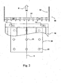
- upstream and downstream will be defined with reference to the direction of movement of the plate elements 10, as illustrated by the arrow D in the figure 2 .
- These elements move from upstream to downstream, generally following the main axis X of the machine, in a movement clocked by periodic stops.
- the front edge of a plate element corresponds to the downstream and the rear edge to the upstream.
- the longitudinal and lateral adjectives are defined with respect to this main axis X.
- the terms plate elements and sheets will be considered as equivalent, and will concern both elements composed of corrugated cardboard as of cardboard, paper or any other material commonly used in the packaging industry.
- the figure 1 shows a schematic overview of a processing machine 1 in which the method of the present invention can be applied.
- This machine comprises a series of processing stations, among which there will typically be an introduction station 2 followed by a cutting station 3, a waste ejection station 4 and a receiving station 5.
- the number and kind of treatment stations which may vary according to the complexity of the shaping operations to be performed on plate elements 10.
- these plate elements 10 are arranged in a stack 11, which is supported in particular against a gauge 6 also acting as a front stop for these elements. Thanks to the gap left at the bottom of the gauge 6, these elements can be removed one by one from the bottom of a stack 11 and then transmitted to an introducer 20.
- This device will allow each of the elements 10 to be inserted into an organ gripping 31 of a conveyor 30, as best seen in the figure 2 .
- This conveyor generally consists of a chain train 32, between the chains of which are arranged a plurality of clamp bars, each acting as a gripping member 31 for the plate member 10.
- the chain train 32 moves and stops periodically so that during a movement, each gripper 31 has moved from one station to the adjacent downstream station.
- the position of the stops of the gripping members 31 is dictated by a movement of the chain train 32 a constant distance. This distance corresponds to the theoretical pitch of these organs on the train of chains.
- the treatment stations 2, 3, 4 and 5 are fixed and spaced apart so that at each stop, the gripping members 31 stop locating with the tools of these stations. Such a type of machine is most often used to treat corrugated board elements.
- the figure 2 represents, in a schematic view from above, a downstream portion of a plate member 10 moving in the direction of a gripper bar by the introducer 20.
- the introducer 20 is provided with a fastening device 21 consisting of a suction pad.
- This fastening device 21 makes it possible to suck the plate member of the bottom of the stack 11 and thus make it integral with the introducer 20, which will slide the plate member 10 under the gauge 6 and bring it into a specific position engaged with the clamps of the gripping member 31.
- the trajectory of the introducer 20 depends on the initial position of the plate member 10 at the bottom of the stack. This position is measured by first sensors 7 located directly downstream of the gauge 6 ( figure 1 ).
- the sensors 7 measure the intensity of light reflected from the surface of the plate member 10 when illuminated by a lighting device, in a predetermined area in which the registration marks are located. A signal processing obtained then makes it possible to calculate the position of the registration mark.
- the lighting device is sometimes integrated in the sensor 7 without this being a necessity.
- the sensors 7 integrate the lighting devices.
- a calculation and control unit 40 for calculating the position of the registration marks and the trajectory of the introducer 20. Knowing the position theoretical stop of the gripping member 31 in the introduction station, the control unit is capable of calculating the values of the displacement parameters (lateral, longitudinal or transverse) of the introducer 20, so as to that the latter correctly brings the plate element 10 which it carries in the gripping member 31, according to its initial starting position. These calculations are carried out by the calculation and control unit 40 which also controls the introducer 20.
- the plate member 10 will then be transported by the gripping member 31 in the cutting station 3, where it will be cut into a die corresponding to the desired shape, for example in order to obtain a plurality of boxes of a given form.
- this station or in one or more subsequent stations, can also be performed other operations such as creasing fold lines, embossing some surfaces and / or the removal of patterns from metallized strips for example.
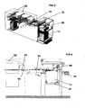
- the figure 3 represents another example of a cutting press known to date in which the plate elements 10 to be worked are sheets taken from above a stack 11, arranged in the form of a sheet and then transported on a margin table before being introduced in the clamps 31 of the transport members 30 of the cutting station of the press.
- the document EP1170228 discloses an example of a sheet feeder for tableting; and the document EP0680906 describes an example of a transport member of the cutting station of the press, using pinch bars.
- the devices for tableclothing the sheets and for routing the sheet are shown in greater detail on the figure 4 .
- the stack 11 is tableted by the suction unit 50, the top of the stack 11 being maintained at a constant level by lifting the battery holder 51 driven by a motor 52.
- the sheet on the top of the stack 11 is grasped by the rear and then pushed forward by the suction group 50, so as to form the sheet, the front part of the sheet 10 coming to slip under the previous sheet.
- the sheets of the sheet are precisely positioned longitudinally and laterally by a positioning device 60 which has a similar operation to that of the introducer 20 of the treatment machine shown on the figures 1 and 2 .
- the document EP 1044908 discloses an example of a sheet positioning device of which the web 3 is made. As described in this document, the positioning takes place at the end of the closest margin table of the transport members 5 of the cutting station, using a sophisticated system that does not require the leaves to stop.
- the positioning device 60 comprises a tablet provided with a fastening device comprising clamps, whose function identical to that of the suction plate 21 of the introducer 20 shown in FIG.
- FIG. 2 is to make a plate element 10 integral with the tablet, to transport it in the gripping member 31, according to its initial starting position in a manner similar to that described above.
- sensors measure the reflected light intensity, which makes it possible to calculate the position of the registration marks and the displacement that the tablet of the positioning device has to perform in order to correctly position the front edge of the plate element in the body.
- This type of press is most often used when the plate elements 10 are sheets of cardboard.
- the present invention therefore aims to ensure perfect positioning of the plate elements 10 in the gripping members 31, with a greatly increased position correction capacity, so as to reduce the number machine stops related to positioning errors out of tolerance.
- the invention concerns both the positioning method and the plate element processing machines capable of implementing this positioning method.
- the term introducer will be used to designate a device whose function is to introduce the downstream edge of a plate member into the gripping member. 31. Such a device corresponds to the introducer 20 represented on the figures 1 and 2 , or to the positioning device 60 shown in the figure 3 and detailed in the document EP1044908 .
- the introducer is provided with a fixing device which makes it possible to make the plate element integral with the introducer.
- the fixing device could take different forms, such as that of a suction plate 21 shown on the drawing. figure 2 , or that of pliers.
- a plate processing machine conventionally comprises an introducer 20 provided with a fixing device 21.
- the introducer 20 makes it possible to position the plate elements 10 in a plurality of gripping members 31 of FIG. a carrier 30, which transports them in running time in successive stations.
- a processing machine comprises at least three sensors 7 which measure the luminous intensity reflected by the surface of the plate element when it is secured to the introducer 20 by the device of FIG. fastening 21, so as to measure the position of registration marks 12 which are printed there.
- One of the sensors 7 is able to measure the lateral position of a registration mark 12 printed on a lateral edge of the plate element 10, and the two other sensors 7 are able to measure the longitudinal position of two marks of 12 marked on the front edge of the plate member 10.
- the treatment machine according to the invention preferably comprises three lighting devices, typically LED type, placed so as to illuminate the registration marks 12 printed, to improve the measurements made by the sensors 7.
- the lighting devices can be advantageously integrated in the sensors 7, which provides advantages in terms of size, ease of assembly and melanic adjustment, but also in terms of maintenance.
- the processing machine comprises drive devices, typically linear motors, able to move the introducer 20.
- a lateral drive device makes it possible to move the introducer 20 in the lateral direction.
- Two longitudinal drive devices make it possible to move the introducer 20 in the longitudinal direction. When the two longitudinal drive devices receive different signals they cause a rotational movement of the introducer 20 about an axis perpendicular to its surface and possibly the surface of the plate element that it carries.
- the processing machine also comprises a calculation and control unit 40, of the microprocessor or micro-controller type.
- the calculation and control unit receives the measurements made by the sensors 7, and calculates lateral, longitudinal and angular positioning errors as a function of these measurements and theoretical positions that should be available to them. marking marks of the plate element carried by the introducer 20.
- the computing and control unit 40 drives the drive devices that move the introducer 20 to correct these lateral, longitudinal and angular positioning errors, to ensure a perfect positioning of the front edge of the plate member 10 in a gripping member 21.
- the positioning method according to the invention differs from the existing methods in that it comprises additional steps, which also occur during the advance of the plate member 10 but before it is secured to the introducer 20 by the fixing device 21.
- a first additional step consists in measuring longitudinal and angular positioning errors of the one of the transverse edges of the plate member 10, that is to say either its front edge or its rear edge.
- a second additional step consists in controlling the introducer 20 as a function of the longitudinal positioning error and the angular positioning error measured.
- the fixing device 21 grasps each plate element in the same way. However, this does not make it possible to correct simultaneous significant longitudinal and angular positioning errors, because the input can not be correctly performed.
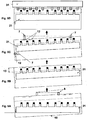
- FIGS. 5A and 5B schematically represent the positioning method according to.
- a plate element 10 has a high angular positioning error and an indifferent longitudinal positioning error.
- Two frontal sensors 8 make it possible to measure both the longitudinal positioning error and the angular positioning error.
- the Figure 5B represents the moment when the fixing device 21 makes the plate element 10 integral with the introducer 20. As the latter has been controlled as a function of the measured positioning errors, the fastening device 21 grasps the plate element 10 to the fly by pinching it precisely in the frontal waste 13 which is on the front edge.
- Figures 5C schematically represents the measurement of the lateral, longitudinal and angular positioning errors of the plate element 10 by means of the sensors 7.
- Figure 5D schematically represents the positioning of the element plate 10 when it is gripped by the clamps of the gripping member 31.
- a processing machine comprises at least two sensors 8 able to detect the passage of a longitudinal edge of the plate member 10, when the latter is moving but before it is entered on the fly by the fixing device 21 to make it integral with the introducer 20. Therefore the sensors 8 are placed upstream of the sensors 7. On the Figures 5 , it is the passage of the front edge which is detected. Alternatively, it is quite possible to measure the positioning of the upstream edge and detecting the passage of the rear edge of the plate member 10. In both cases, the sensors 8 can be of extremely simple construction. For example the breaks of two light beams are sufficient to detect the passage of the front edge. Alternatively, the sudden change in the signal provided by inductive sensors sliding or rolling on the surface of the plate element makes it easy to detect the trailing edge.
- the calculation and control unit 40 calculates the positioning errors, by knowing the speed of movement, then pilot the introducer 20 by sending control signals to the transverse drive device and the longitudinal drive devices.
- This method and the machines that implement it thus make it possible to correct significant simultaneous longitudinal positioning and angular positioning errors. And significantly reduce the risk of machine shutdown due to out of tolerance positioning errors.
Description
La présente invention a pour objet un dispositif et un procédé de positionnement d'éléments en plaque dans la station d'introduction d'une machine de traitement d'éléments en plaque, ainsi qu'une machine de traitement d'éléments en plaque comprenant ledit dispositif ou mettant en oeuvre ledit procédé.The present invention relates to a device and a method for positioning plate elements in the introduction station of a plate-like processing machine, as well as a plate-like processing machine comprising said device or implementing said method.
De telles machines sont utilisées notamment dans l'industrie de l'impression et de l'emballage, par exemple pour la confection de boîtes en carton à partir d'éléments en plaque tels que des feuilles de carton pré-imprimées. Dans une station d'introduction, ces feuilles sont retirées d'une pile située en amont de la machine, puis sont ensuite positionnées par un introducteur dans des barres de pinces montées à intervalles réguliers sur un train de chaînes sans fin subséquent. Ce dernier permet de transporter les feuilles dans les différentes stations de traitement ultérieures de la machine. Typiquement, de telles stations sont vouées au découpage des feuilles, à l'éjection des déchets de découpage et à la réception en pile de ces feuilles découpées.Such machines are used in particular in the printing and packaging industry, for example for making cardboard boxes from plate elements such as pre-printed cardboard sheets. In an introduction station, these sheets are removed from a stack located upstream of the machine, and are then positioned by an introducer in gripper bars mounted at regular intervals on a subsequent endless chain train. The latter makes it possible to transport the sheets in the various subsequent processing stations of the machine. Typically, such stations are dedicated to the cutting of leaves, the ejection of cutting waste and the receipt in stack of these cut sheets.
Dans un défilement cadencé, le train de chaînes se déplace et s'arrête périodiquement de sorte que, durant chaque déplacement, toutes les barres de pinces en prise avec une feuille sont passées d'une station à la station aval adjacente. Si l'on désire obtenir une impression ou un façonnage de qualité, le positionnement des feuilles au sein des différentes stations successives est une opération primordiale. Dans le cas du découpage d'une feuille imprimée, le positionnement de la feuille dans la station de découpage doit être précis. En effet, il convient de veiller à ce que les outils servant au découpage, par exemple la forme à découper d'une presse à platine, soient en parfait registre avec l'impression qui a été faite au préalable sur la feuille.In a timed run, the train of chains moves and stops periodically so that during each move, all the gripper bars engaged with a sheet are moved from one station to the adjacent downstream station. If one wishes to obtain a printing or a shaping of quality, the positioning of the sheets within the different successive stations is a primordial operation. In the case of cutting a printed sheet, the positioning of the sheet in the cutting station must be precise. Indeed, it should be ensured that the tools used for cutting, for example the cutting form of a platen press, are in perfect condition. register with the impression that has been made beforehand on the sheet.
Le brevet
Le brevet
Le dispositif et le procédé décrit dans document
Le but de la présente invention vise à remédier aux inconvénients précités, et à améliorer la qualité obtenue. L'invention permet également de corriger des erreurs de positionnement plus importantes et donc de réduire le risque d'arrêt machine lié à une erreur de positionnement d'un élément en plaque qui serait hors tolérance.The object of the present invention is to overcome the aforementioned drawbacks, and to improve the quality obtained. The invention also makes it possible to correct larger positioning errors and thus to reduce the risk of machine stoppage linked to a positioning error of a plate element that is out of tolerance.
A cet effet, la présente invention a pour objet un procédé de positionnement d'éléments en plaque au sein d'une machine, conformément à ce qu'énonce la revendication 1, et une machine de traitement d'élément en plaque mettant en oeuvre ce procédé conformément à ce qu'énonce la revendication 2.To this end, the subject of the present invention is a method of positioning plate elements within a machine, as set forth in claim 1, and a plate element processing machine implementing this process according to claim 2.
L'invention sera mieux comprise à l'étude de modes de réalisation pris à titre nullement limitatif et illustrés par les figures annexées dans lesquelles:
- La
figure 1 est une représentation schématique d'un premier type de machine de traitement au sein de laquelle défilent des éléments en plaque transportés par des barres de pinces. - La
figure 2 est une vue schématique en plan du bord frontal d'un élément en plaque en déplacement en direction d'une barre de pinces en vue d'être saisi par cette dernière. - Les
figures 3 et 4 sont des représentations schématiques d'un second type de machiné de traitement au sein de laquelle défilent des éléments en plaque transportés par des barres de pinces. - Les
Figures 5A a 5D représentent schématiquement la mise en oeuvre du procédé selon l'invention par une machine de traitement selon l'invention.
- The
figure 1 is a schematic representation of a first type of processing machine in which plate elements carried by gripper bars run past. - The
figure 2 is a schematic plan view of the front edge of a plate member moving in the direction of a clip bar for gripping by the latter. - The
Figures 3 and 4 are diagrammatic representations of a second type of processing machine in which plate elements transported by gripper bars pass. - The
Figures 5A 5D show schematically the implementation of the method according to the invention by a processing machine according to the invention.
Afin d'éviter toute confusion dans la description qui va suivre, on définira les termes amont et aval en référence au sens de déplacement des éléments en plaque 10, tel qu'illustré par la flèche D dans la
La
Dans la station d'introduction 2, ces éléments en plaque 10 sont disposés en une pile 11, laquelle prend appui notamment contre une jauge 6 faisant également office de butée frontale pour ces éléments. Grâce à l'interstice laissé au bas de la jauge 6, ces éléments peuvent être retirés un à un du bas d'une pile 11 puis transmis à un introducteur 20. Ce dispositif va permettre d'introduire chacun des éléments 10 dans un organe de préhension 31 d'un transporteur 30, comme mieux visible dans la
Le train de chaînes 32 se déplace et s'arrête périodiquement de sorte que durant un déplacement, chaque organe de préhension 31 est passé d'une station à la station aval adjacente. La position des arrêts des organes de préhension 31 est dictée par un déplacement du train de chaînes 32 d'une distance constante. Cette distance correspond au pas théorique de ces organes sur le train de chaînes. Les stations de traitement 2, 3, 4 et 5 sont fixes et distancées de ce même pas de sorte qu'à chaque arrêt, les organes de préhension 31 stoppent en repérage avec les outils de ces stations. Un tel type de machine est le plus souvent utilisé pour traiter des éléments en plaque de carton ondulé.The
La
Dès que les mesures sont effectuées par lesdits premiers capteurs 7, ces mesures sont immédiatement transmises à une unité de calcul et de contrôle 40 pour le calcul de la position des marques de repérages et de la trajectoire de l'introducteur 20. Connaissant la position théorique d'arrêt de l'organe de préhension 31 dans la station d'introduction, l'unité de contrôle est capable de calculer les valeurs des paramètres du déplacement (latéral, longitudinal ou de travers) de l'introducteur 20, de façon à ce que ce dernier amène correctement l'élément en plaque 10 qu'il transporte dans l'organe de préhension 31, en fonction de sa position initiale de départ. Ces calculs sont effectués par l'unité de calcul et de contrôle 40 qui pilote également l'introducteur 20.As soon as the measurements are made by said
L'élément en plaque 10 va ensuite être transporté par l'organe de préhension 31 dans la station de découpage 3, où il sera découpé selon une matrice correspondant à la forme développée que l'on souhaite obtenir, par exemple en vue d'obtenir une pluralité de boîtes d'une forme donnée. Dans cette station, ou dans une ou plusieurs stations ultérieures, peuvent également être effectuées d'autres opérations telles que le refoulage de lignes de pliage, le gaufrage de certaines surfaces et/ou la dépose de motifs à partir de bandes métallisées par exemple.The
La
Les dispositifs de mise en nappe des feuilles et de cheminement de la nappe sont représentés plus en détail sur la
Les feuilles de la nappe sont précisément positionnées longitudinalement et latéralement par un dispositif de positionnement 60 qui a un fonctionnement semblable à celui de l'introducteur 20 de la machine de traitement représentée sur les
La présente invention a donc pour but d'assurer un positionnement parfait des éléments en plaque 10 dans les organes de préhension 31, avec une capacité de correction de position fortement augmentée, de façon à réduire le nombre d'arrêts de la machine liés à des erreurs de positionnement hors tolérance. L'invention concerne aussi bien le procédé de positionnement que les machines de traitement d'éléments en plaque aptes à mettre en oeuvre ce procédé de positionnement. Dans la description détaillée qui va suivre d'exemples de mise en oeuvre de l'invention le terme introducteur sera utilisé pour désigner un dispositif dont la fonction est d'introduire le bord aval d'un élément en plaque 10 dans l'organe de préhension 31. Un tel dispositif correspond à l'introducteur 20 représenté sur les
Pour la suite de la description, la terminologie et la numérotation des éléments seront celles des
Une machine de traitement en plaque conforme à l'invention comporte de façon classique un introducteur 20 muni d'un dispositif de fixation 21. L'introducteur 20 permet de positionner les éléments en plaque 10 dans une pluralité d'organes de préhension 31 d'un transporteur 30, qui les transporte en défilement cadencé dans des stations successives. De façon classique également, une machine de traitement selon l'invention comporte au moins trois capteurs 7 qui mesurent l'intensité lumineuse réfléchie par la surface de l'élément en plaque lorsqu'il est rendu solidaire de l'introducteur 20 par le dispositif de fixation 21, de façon à mesurer la position de marques de repérage 12 qui y sont imprimées. L'un des capteurs 7 est apte à mesurer la position latérale d'une marque de repérage 12 imprimée sur un bord latéral de l'élément en plaque 10, et les deux autres capteurs 7 sont aptes à mesurer la position longitudinale de deux marques de repérage 12 imprimées sur le bord avant de l'élément en plaque 10.A plate processing machine according to the invention conventionally comprises an
La machine de traitement selon l'invention comprend préférentiellement trois dispositifs d'éclairage, typiquement de type LED, placés de façon à éclairer les marques de repérage 12 imprimées, pour améliorer les mesures effectuées par les capteurs 7. Les dispositifs d'éclairage peuvent être avantageusement intégrés dans les capteurs 7, ce qui procure des avantages en terme d'encombrement, de facilité de montage et de réglage mélanique, mais également en terme de maintenance.The treatment machine according to the invention preferably comprises three lighting devices, typically LED type, placed so as to illuminate the registration marks 12 printed, to improve the measurements made by the
La machine de traitement selon l'invention comprend des dispositifs d'entrainement, typiquement des moteurs linéaires, aptes à déplacer l'introducteur 20. Un dispositif d'entrainement latéral permet de déplacer l'introducteur 20 dans le sens latéral. Deux dispositifs d'entraînement longitudinal permettent de déplacer l'introducteur 20 dans le sens longitudinal. Lorsque les deux dispositifs d'entrainement longitudinal reçoivent des signaux différents ils provoquent un mouvement de rotation de l'introducteur 20 autour d'un axe perpendiculaire à sa surface et éventuellement à la surface de l'élément en plaque qu'il transporte.The processing machine according to the invention comprises drive devices, typically linear motors, able to move the
La machine de traitement conforme à l'invention comprend également une unité de calcul et de contrôle 40, de type micro-processeur ou micro-contrôleur. L'unité de calcul et de contrôle reçoit les mesures effectuées par les capteurs 7, et calcule des erreurs de positionnement latéral, longitudinal et angulaire en fonction de ces mesures et des positions théoriques que devraient avoir les marques de repérage de l'élément en plaque transporté par l'introducteur 20.The processing machine according to the invention also comprises a calculation and
L'unité de calcul et de contrôle 40 pilote les dispositifs d'entrainement qui déplacent l'introducteur 20 de façon à corriger ces erreurs de positionnement latéral, longitudinal et angulaire, pour assurer un positionnement parfait du bord avant de l'élément en plaque 10 dans un organe de préhension 21.The computing and
Tous ces éléments sont déjà connus en combinaison. Ils permettent de mettre en oeuvre un procédé comparable à celui décrit dans le document
Il est essentiel que toutes ces étapes se produisent pendant l'avance de chaque élément en plaque 10. Cela implique en particulier que cet élément en plaque est saisi à la volée par le dispositif de fixation 21, sans s'arrêter, et que les mesures et les corrections sont également effectuées pendant cette avance. Ainsi l'élément en plaque 10 ne cesse jamais d'avancer, ce qui permet d'atteindre des cadences de traitement très élevées de l'ordre de 12 000 feuilles par heure.It is essential that all these steps occur during the advance of each
Le procédé de positionnement selon invention se distingue des procédés existants par le fait qu'il comprend des étapes supplémentaires, qui se produisent également pendant l'avance de l'élément en plaque 10 mais avant que qu'il ne soit rendu solidaire de l'introducteur 20 par le dispositif de fixation 21. Une première étape additionnelle consiste à mesurer des erreurs de positionnement longitudinal et angulaire de l'un des bords transversaux de l'élément en plaque 10, c'est-à-dire soit son bord avant, soit son bord arrière. Une seconde étape additionnelle consiste à piloter l'introducteur 20 en fonction de l'erreur de positionnement longitudinal et de l'erreur de positionnement angulaire mesurées.The positioning method according to the invention differs from the existing methods in that it comprises additional steps, which also occur during the advance of the
En effet dans les systèmes existants, le dispositif de fixation 21 saisit chaque élément en plaque de la même manière. Or ceci ne permet pas de corriger des erreurs significative simultanées de positionnement longitudinal et angulaire, car la saisie ne pourra pas être effectuée correctement.Indeed, in existing systems, the fixing
Les
La
La
Ainsi une machine de traitement selon l'invention comporte-t-elle au moins deux capteurs 8 aptes à détecter le passage d'un bord longitudinal de l'élément en plaque 10, lorsque ce dernier est en mouvement mais avant qu'il soit saisi à la volée par le dispositif de fixation 21 pour le rendre solidaire de l'introducteur 20. Par conséquent les capteurs 8 sont placés en amont des capteurs 7. Sur les
Dans les deux cas, c'est un temps de passage qui est déterminé par l'unité de calcul et de contrôle 40 grâce aux mesures envoyées par les capteurs 8. L'unité de calcul et de contrôle 40 calcule alors les erreurs de positionnement, en connaissant la vitesse de déplacement, puis pilote en conséquence l'introducteur 20 en envoyant des signaux de commande au dispositif d'entrainement transversal et aux dispositifs d'entrainement longitudinal.In both cases, it is a passage time that is determined by the calculation and
Ce procédé et les machines qui le mettent en oeuvre permettent ainsi de corriger des erreurs significatives simultanées de positionnement longitudinal et de positionnement angulaire. Et de réduire considérablement le risque d'arrêt de la machine à cause d'erreurs de positionnement hors tolérance.This method and the machines that implement it thus make it possible to correct significant simultaneous longitudinal positioning and angular positioning errors. And significantly reduce the risk of machine shutdown due to out of tolerance positioning errors.
Claims (4)
- Method for placing plate-like elements (10) within a processing machine (1) comprising a feeder (20) for placing these plate-like elements (10) in a plurality of gripping members (31) of a conveyor (30) which conveys them in a paced flow into successive stations (3, 4, 5), said feeder (20) being furnished with a fixing device (21), said feeder (20) being driven by a computation and control unit (40), comprising the successive steps consisting in:- during the advancement of each plate-like element (10):- measuring the longitudinal placement error and the angular placement error of the plate-like element (10) relative to a theoretical position, by detecting the front edge or the rear edge of the plate-like element (10),- controlling the feeder (20) according to the measured longitudinal placement error and the angular placement error,- activating the fixing device (21) in order to make said plate-like element (10) attached to the feeder (20), characterized in that it comprises the successive steps consisting in:- measuring the longitudinal placement error, the transverse placement error and the angular placement error of the plate-like element (10) attached to the feeder (20), relative to a theoretical position, by detecting register marks (12) printed on said plate-like element (10),- controlling the feeder (20) according to the placement errors of the plate-like element (10) to which it is attached.
- Machine for processing plate-like elements comprising- a feeder (20) furnished with a fixing device (21) for placing these plate-like elements (10) in a plurality of gripping members (31) of a conveyor (30) which conveys said plate-like elements in a paced flow into successive stations (3, 4, 5);- a lateral driving device capable of moving the feeder (20) in the lateral direction;- two longitudinal driving devices capable of moving the feeder (20) in the longitudinal direction;- at least three sensors (7) capable of measuring the light intensity reflected by the surface of the plate-like element (10);- a computation and control unit (40) receiving the measurements from said sensors (7) and controlling said lateral driving device, said longitudinal driving devices and said fixing device (21); characterized in that- it also comprises at least two sensors (8) capable of detecting the passage of a longitudinal edge of the plate-like element (10); the sensors (8) being placed upstream of the sensors (7), and being connected to the computation and control unit (40).
- Machine for processing plate-like elements according to Claim 2, characterized in that said sensors (8) are capable of detecting the passage of the front edge of the plate-like element (10).
- Machine for processing plate-like elements according to Claim 2, characterized in that said sensors (8) are capable of detecting the passage of the rear edge of the plate-like element (10).
Priority Applications (2)
| Application Number | Priority Date | Filing Date | Title |
|---|---|---|---|
| EP10737770.7A EP2456698B1 (en) | 2009-07-24 | 2010-07-16 | Device and method for positioning elements on a plate in a processing machine |
| PL10737770T PL2456698T3 (en) | 2009-07-24 | 2010-07-16 | Device and method for positioning elements on a plate in a processing machine |
Applications Claiming Priority (3)
| Application Number | Priority Date | Filing Date | Title |
|---|---|---|---|
| EP09009620 | 2009-07-24 | ||
| EP10737770.7A EP2456698B1 (en) | 2009-07-24 | 2010-07-16 | Device and method for positioning elements on a plate in a processing machine |
| PCT/EP2010/004332 WO2011009567A1 (en) | 2009-07-24 | 2010-07-16 | Device and method for positioning plate elements in a treatment machine |
Publications (2)
| Publication Number | Publication Date |
|---|---|
| EP2456698A1 EP2456698A1 (en) | 2012-05-30 |
| EP2456698B1 true EP2456698B1 (en) | 2015-03-11 |
Family
ID=41496191
Family Applications (1)
| Application Number | Title | Priority Date | Filing Date |
|---|---|---|---|
| EP10737770.7A Active EP2456698B1 (en) | 2009-07-24 | 2010-07-16 | Device and method for positioning elements on a plate in a processing machine |
Country Status (10)
| Country | Link |
|---|---|
| US (1) | US8960410B2 (en) |
| EP (1) | EP2456698B1 (en) |
| JP (1) | JP5256377B2 (en) |
| KR (1) | KR101273058B1 (en) |
| CN (1) | CN102471000B (en) |
| BR (1) | BR112012001594B1 (en) |
| CA (1) | CA2768784C (en) |
| ES (1) | ES2534487T3 (en) |
| PL (1) | PL2456698T3 (en) |
| WO (1) | WO2011009567A1 (en) |
Cited By (10)
| Publication number | Priority date | Publication date | Assignee | Title |
|---|---|---|---|---|
| CN109311611A (en) * | 2016-05-24 | 2019-02-05 | 鲍勃斯脱梅克斯股份有限公司 | For placing register device, processing machine and the method for fuel plate |
| WO2023148013A1 (en) | 2022-02-04 | 2023-08-10 | Koenig & Bauer Ag | Processing machine and method for aligning a substrate in a processing machine |
| WO2023148014A1 (en) | 2022-02-04 | 2023-08-10 | Koenig & Bauer Ag | Processing machines and method for the relative orientation of a substrate to a processing unit in a processing machine |
| DE102022125019A1 (en) | 2022-09-28 | 2024-03-28 | Koenig & Bauer Ag | Processing machine and method for controlling at least one alignment section of a processing machine |
| DE102022125017A1 (en) | 2022-09-28 | 2024-03-28 | Koenig & Bauer Ag | Processing machine and method for controlling at least one alignment section of a processing machine |
| DE102022125020A1 (en) | 2022-09-28 | 2024-03-28 | Koenig & Bauer Ag | Method for the axial adjustment of transport sections of at least one alignment section |
| DE102022125016A1 (en) | 2022-09-28 | 2024-03-28 | Koenig & Bauer Ag | Method for the axial adjustment of transport sections of at least one alignment section |
| DE102022125018A1 (en) | 2022-09-28 | 2024-03-28 | Koenig & Bauer Ag | Processing machine and method for controlling at least one alignment section of a processing machine |
| DE102022125022A1 (en) | 2022-09-28 | 2024-03-28 | Koenig & Bauer Ag | Method for controlling at least one alignment section of a processing machine |
| DE102022125021A1 (en) | 2022-09-28 | 2024-03-28 | Koenig & Bauer Ag | Method for the axial adjustment of transport sections of at least one alignment section |
Families Citing this family (7)
| Publication number | Priority date | Publication date | Assignee | Title |
|---|---|---|---|---|
| DE102016203674A1 (en) * | 2016-03-07 | 2017-09-07 | Homag Gmbh | Method for operating a continuous machine and continuous machine |
| PL3426449T3 (en) * | 2016-03-09 | 2020-06-01 | Bobst Mex Sa | Ejector and machine for treating sheet-shaped elements |
| CN105892107A (en) * | 2016-04-15 | 2016-08-24 | 京东方科技集团股份有限公司 | Automatic laminating equipment and automatic laminating method |
| SG10201704185YA (en) * | 2017-05-23 | 2018-12-28 | Hock Hai Low | Method of aligning a flat or profiled metal sheet |
| CN108217292B (en) * | 2018-01-15 | 2023-08-25 | 东莞市鼎力自动化科技有限公司 | Automatic machine for folding roll paper plate |
| JP6888645B2 (en) * | 2019-05-08 | 2021-06-16 | トヨタ自動車株式会社 | Transfer device and transfer method |
| DE102019133550B4 (en) * | 2019-12-09 | 2022-03-10 | Koenig & Bauer Ag | Method for the relative change in position of at least one means of transport of at least one feed system of a sheet processing machine and sheet processing machine |
Family Cites Families (10)
| Publication number | Priority date | Publication date | Assignee | Title |
|---|---|---|---|---|
| GB2128772A (en) * | 1982-10-18 | 1984-05-02 | Philips Electronic Associated | Automatic assembly apparatus |
| CH690098A5 (en) | 1994-05-04 | 2000-04-28 | Bobst Sa | Gripper bar comprising a fastening device with an undercarriage in a machine processing plate elements. |
| CH690470A5 (en) * | 1994-06-17 | 2000-09-15 | Bobst Sa | Device to ensure the quality of the production of a press for manufacturing packages. |
| US6085407A (en) * | 1997-08-21 | 2000-07-11 | Micron Technology, Inc. | Component alignment apparatuses and methods |
| CH693378A5 (en) * | 1999-04-09 | 2003-07-15 | Bobst Sa | A method of positioning sheet elements in the introduction station of a processing machine and device for carrying out the method. |
| US6229608B1 (en) * | 1999-06-10 | 2001-05-08 | Pmj Automec Oyj | Procedure and system for inspecting a component with leads to determine its fitness for assembly |
| CH693850A5 (en) | 2000-05-16 | 2004-03-15 | Bobst Sa | A servo-control bodies delivering sheets to a machine. |
| JP2005231887A (en) * | 2004-02-23 | 2005-09-02 | Sharp Corp | Paper feeding device and image forming device |
| ES2323964T3 (en) * | 2005-10-05 | 2009-07-28 | Bobst S.A. | PROCEDURE FOR THE POSITIONING OF ELEMENTS IN THE FORM OF A PLATE IN A TREATMENT MACHINE. |
| DE202007012349U1 (en) * | 2006-07-26 | 2007-12-13 | Heidelberger Druckmaschinen Ag | Sheet punching and embossing machine with register alignment |
-
2010
- 2010-07-16 KR KR1020127001579A patent/KR101273058B1/en active IP Right Grant
- 2010-07-16 CN CN201080032180.1A patent/CN102471000B/en active Active
- 2010-07-16 BR BR112012001594A patent/BR112012001594B1/en active IP Right Grant
- 2010-07-16 ES ES10737770.7T patent/ES2534487T3/en active Active
- 2010-07-16 CA CA2768784A patent/CA2768784C/en active Active
- 2010-07-16 US US13/386,216 patent/US8960410B2/en active Active
- 2010-07-16 WO PCT/EP2010/004332 patent/WO2011009567A1/en active Application Filing
- 2010-07-16 JP JP2012520939A patent/JP5256377B2/en active Active
- 2010-07-16 EP EP10737770.7A patent/EP2456698B1/en active Active
- 2010-07-16 PL PL10737770T patent/PL2456698T3/en unknown
Cited By (12)
| Publication number | Priority date | Publication date | Assignee | Title |
|---|---|---|---|---|
| CN109311611A (en) * | 2016-05-24 | 2019-02-05 | 鲍勃斯脱梅克斯股份有限公司 | For placing register device, processing machine and the method for fuel plate |
| WO2023148013A1 (en) | 2022-02-04 | 2023-08-10 | Koenig & Bauer Ag | Processing machine and method for aligning a substrate in a processing machine |
| WO2023148014A1 (en) | 2022-02-04 | 2023-08-10 | Koenig & Bauer Ag | Processing machines and method for the relative orientation of a substrate to a processing unit in a processing machine |
| DE102022125019A1 (en) | 2022-09-28 | 2024-03-28 | Koenig & Bauer Ag | Processing machine and method for controlling at least one alignment section of a processing machine |
| DE102022125017A1 (en) | 2022-09-28 | 2024-03-28 | Koenig & Bauer Ag | Processing machine and method for controlling at least one alignment section of a processing machine |
| DE102022125020A1 (en) | 2022-09-28 | 2024-03-28 | Koenig & Bauer Ag | Method for the axial adjustment of transport sections of at least one alignment section |
| DE102022125016A1 (en) | 2022-09-28 | 2024-03-28 | Koenig & Bauer Ag | Method for the axial adjustment of transport sections of at least one alignment section |
| DE102022125018A1 (en) | 2022-09-28 | 2024-03-28 | Koenig & Bauer Ag | Processing machine and method for controlling at least one alignment section of a processing machine |
| DE102022125022A1 (en) | 2022-09-28 | 2024-03-28 | Koenig & Bauer Ag | Method for controlling at least one alignment section of a processing machine |
| DE102022125021A1 (en) | 2022-09-28 | 2024-03-28 | Koenig & Bauer Ag | Method for the axial adjustment of transport sections of at least one alignment section |
| WO2024068151A1 (en) | 2022-09-28 | 2024-04-04 | Koenig & Bauer Ag | Method for controlling at least one alignment line of a processing machine |
| WO2024068150A1 (en) | 2022-09-28 | 2024-04-04 | Koenig & Bauer Ag | Processing machine, and method for controlling at least one alignment line of a processing machine |
Also Published As
| Publication number | Publication date |
|---|---|
| KR20120031501A (en) | 2012-04-03 |
| CA2768784C (en) | 2015-06-16 |
| BR112012001594A2 (en) | 2016-03-08 |
| CN102471000A (en) | 2012-05-23 |
| JP2013500218A (en) | 2013-01-07 |
| US20120118703A1 (en) | 2012-05-17 |
| ES2534487T3 (en) | 2015-04-23 |
| PL2456698T3 (en) | 2015-06-30 |
| EP2456698A1 (en) | 2012-05-30 |
| CN102471000B (en) | 2014-12-10 |
| BR112012001594B1 (en) | 2020-01-28 |
| JP5256377B2 (en) | 2013-08-07 |
| US8960410B2 (en) | 2015-02-24 |
| WO2011009567A1 (en) | 2011-01-27 |
| KR101273058B1 (en) | 2013-06-10 |
| CA2768784A1 (en) | 2011-01-27 |
Similar Documents
| Publication | Publication Date | Title |
|---|---|---|
| EP2456698B1 (en) | Device and method for positioning elements on a plate in a processing machine | |
| EP2391566B1 (en) | Device for positioning a flat element in an entrance station of a processing machine | |
| EP1772405B1 (en) | Method for positioning plate-shaped products in a treatment machine | |
| EP2356049B1 (en) | Calibration method in a machine for processing elements in plates | |
| EP2512807B1 (en) | Hot-stamping printing device | |
| EP0441596A1 (en) | Image applying apparatus | |
| EP0138641B1 (en) | Automatic device for maintaining proper registry of a tool fitted on a motating cylinder for the treatment of sheetlike products | |
| CA2558947C (en) | Method and apparatus for manufacture and inspection of swatch bearing sheets using a vacuum conveyor | |
| EP3003703A1 (en) | Unit for transforming a substrate in a continuous band and wrapping production machine equipped with same | |
| JP4153648B2 (en) | Seedling spacing adjustment method and apparatus | |
| EP0612679A1 (en) | Apparatus for delivering semi-rigid sheets, particularly cardboard, from a stack | |
| RU2700093C1 (en) | Registration device, processing machine and method of arrangement of sheet elements | |
| FR2813036A1 (en) | ROTARY OFFSET PRINTING MACHINE HAVING A SYSTEM FOR DETERMINING PRESET DATA FOR THE CUT REGISTER AND / OR THE COLOR REGISTER | |
| EP2834177B1 (en) | Drive device for a web to be embossed, unwinding module and stamping machine equipped therewith | |
| EP0453984B1 (en) | Device for jogging sheets | |
| EP0468842B1 (en) | Method for cutting and dispensing multi-width printed webs and positioning device to carry out this method | |
| FR2676961A1 (en) | METHOD AND DEVICE FOR MAINTAINING, ALIGNING AND MAINTAINING SHEETS ON CYLINDERS OF SHEET MACHINERY | |
| FR2695590A1 (en) | Method and device for orienting sheets | |
| FR2796331A1 (en) | METHOD AND DEVICE FOR MONITORING THE TRANSPORT OF PRINTED OR SIMILAR PRODUCTS, AS WELL AS FOLDER AND ROTARY PRINTING MACHINE USING THE SAME | |
| JP2813338B2 (en) | Wrap device in corrugator | |
| FR2699857A1 (en) | Multicolour printing from transfer tape esp. on to memory chip card | |
| JPH09202494A (en) | Work feed device | |
| WO2007057204A1 (en) | Process and device for obtaining the format and the registration of a preconditioned strip of composite material | |
| BE562016A (en) |
Legal Events
| Date | Code | Title | Description |
|---|---|---|---|
| PUAI | Public reference made under article 153(3) epc to a published international application that has entered the european phase |
Free format text: ORIGINAL CODE: 0009012 |
|
| 17P | Request for examination filed |
Effective date: 20120119 |
|
| AK | Designated contracting states |
Kind code of ref document: A1 Designated state(s): AL AT BE BG CH CY CZ DE DK EE ES FI FR GB GR HR HU IE IS IT LI LT LU LV MC MK MT NL NO PL PT RO SE SI SK SM TR |
|
| RAP1 | Party data changed (applicant data changed or rights of an application transferred) |
Owner name: BOBST MEX SA |
|
| DAX | Request for extension of the european patent (deleted) | ||
| REG | Reference to a national code |
Ref country code: DE Ref legal event code: R079 Ref document number: 602010023055 Country of ref document: DE Free format text: PREVIOUS MAIN CLASS: B65H0009120000 Ipc: B65H0005100000 |
|
| GRAP | Despatch of communication of intention to grant a patent |
Free format text: ORIGINAL CODE: EPIDOSNIGR1 |
|
| RIC1 | Information provided on ipc code assigned before grant |
Ipc: B65H 9/10 20060101ALI20140716BHEP Ipc: B65H 5/10 20060101AFI20140716BHEP Ipc: B65H 7/10 20060101ALI20140716BHEP Ipc: B65H 7/14 20060101ALI20140716BHEP Ipc: B65H 9/12 20060101ALI20140716BHEP Ipc: B65H 7/08 20060101ALI20140716BHEP |
|
| INTG | Intention to grant announced |
Effective date: 20140730 |
|
| GRAJ | Information related to disapproval of communication of intention to grant by the applicant or resumption of examination proceedings by the epo deleted |
Free format text: ORIGINAL CODE: EPIDOSDIGR1 |
|
| GRAS | Grant fee paid |
Free format text: ORIGINAL CODE: EPIDOSNIGR3 |
|
| GRAP | Despatch of communication of intention to grant a patent |
Free format text: ORIGINAL CODE: EPIDOSNIGR1 |
|
| GRAA | (expected) grant |
Free format text: ORIGINAL CODE: 0009210 |
|
| INTG | Intention to grant announced |
Effective date: 20150122 |
|
| AK | Designated contracting states |
Kind code of ref document: B1 Designated state(s): AL AT BE BG CH CY CZ DE DK EE ES FI FR GB GR HR HU IE IS IT LI LT LU LV MC MK MT NL NO PL PT RO SE SI SK SM TR |
|
| REG | Reference to a national code |
Ref country code: GB Ref legal event code: FG4D Free format text: NOT ENGLISH |
|
| REG | Reference to a national code |
Ref country code: CH Ref legal event code: EP |
|
| REG | Reference to a national code |
Ref country code: IE Ref legal event code: FG4D Free format text: LANGUAGE OF EP DOCUMENT: FRENCH |
|
| REG | Reference to a national code |
Ref country code: AT Ref legal event code: REF Ref document number: 715199 Country of ref document: AT Kind code of ref document: T Effective date: 20150415 |
|
| REG | Reference to a national code |
Ref country code: ES Ref legal event code: FG2A Ref document number: 2534487 Country of ref document: ES Kind code of ref document: T3 Effective date: 20150423 Ref country code: DE Ref legal event code: R096 Ref document number: 602010023055 Country of ref document: DE Effective date: 20150423 |
|
| REG | Reference to a national code |
Ref country code: PL Ref legal event code: T3 |
|
| REG | Reference to a national code |
Ref country code: NL Ref legal event code: VDEP Effective date: 20150311 |
|
| REG | Reference to a national code |
Ref country code: NL Ref legal event code: VDEP Effective date: 20150311 |
|
| PG25 | Lapsed in a contracting state [announced via postgrant information from national office to epo] |
Ref country code: NO Free format text: LAPSE BECAUSE OF FAILURE TO SUBMIT A TRANSLATION OF THE DESCRIPTION OR TO PAY THE FEE WITHIN THE PRESCRIBED TIME-LIMIT Effective date: 20150611 Ref country code: HR Free format text: LAPSE BECAUSE OF FAILURE TO SUBMIT A TRANSLATION OF THE DESCRIPTION OR TO PAY THE FEE WITHIN THE PRESCRIBED TIME-LIMIT Effective date: 20150311 Ref country code: SE Free format text: LAPSE BECAUSE OF FAILURE TO SUBMIT A TRANSLATION OF THE DESCRIPTION OR TO PAY THE FEE WITHIN THE PRESCRIBED TIME-LIMIT Effective date: 20150311 Ref country code: FI Free format text: LAPSE BECAUSE OF FAILURE TO SUBMIT A TRANSLATION OF THE DESCRIPTION OR TO PAY THE FEE WITHIN THE PRESCRIBED TIME-LIMIT Effective date: 20150311 Ref country code: LT Free format text: LAPSE BECAUSE OF FAILURE TO SUBMIT A TRANSLATION OF THE DESCRIPTION OR TO PAY THE FEE WITHIN THE PRESCRIBED TIME-LIMIT Effective date: 20150311 |
|
| REG | Reference to a national code |
Ref country code: AT Ref legal event code: MK05 Ref document number: 715199 Country of ref document: AT Kind code of ref document: T Effective date: 20150311 |
|
| REG | Reference to a national code |
Ref country code: LT Ref legal event code: MG4D |
|
| PG25 | Lapsed in a contracting state [announced via postgrant information from national office to epo] |
Ref country code: LV Free format text: LAPSE BECAUSE OF FAILURE TO SUBMIT A TRANSLATION OF THE DESCRIPTION OR TO PAY THE FEE WITHIN THE PRESCRIBED TIME-LIMIT Effective date: 20150311 Ref country code: GR Free format text: LAPSE BECAUSE OF FAILURE TO SUBMIT A TRANSLATION OF THE DESCRIPTION OR TO PAY THE FEE WITHIN THE PRESCRIBED TIME-LIMIT Effective date: 20150612 |
|
| PG25 | Lapsed in a contracting state [announced via postgrant information from national office to epo] |
Ref country code: NL Free format text: LAPSE BECAUSE OF FAILURE TO SUBMIT A TRANSLATION OF THE DESCRIPTION OR TO PAY THE FEE WITHIN THE PRESCRIBED TIME-LIMIT Effective date: 20150311 |
|
| PG25 | Lapsed in a contracting state [announced via postgrant information from national office to epo] |
Ref country code: EE Free format text: LAPSE BECAUSE OF FAILURE TO SUBMIT A TRANSLATION OF THE DESCRIPTION OR TO PAY THE FEE WITHIN THE PRESCRIBED TIME-LIMIT Effective date: 20150311 Ref country code: RO Free format text: LAPSE BECAUSE OF FAILURE TO SUBMIT A TRANSLATION OF THE DESCRIPTION OR TO PAY THE FEE WITHIN THE PRESCRIBED TIME-LIMIT Effective date: 20150311 Ref country code: CZ Free format text: LAPSE BECAUSE OF FAILURE TO SUBMIT A TRANSLATION OF THE DESCRIPTION OR TO PAY THE FEE WITHIN THE PRESCRIBED TIME-LIMIT Effective date: 20150311 Ref country code: PT Free format text: LAPSE BECAUSE OF FAILURE TO SUBMIT A TRANSLATION OF THE DESCRIPTION OR TO PAY THE FEE WITHIN THE PRESCRIBED TIME-LIMIT Effective date: 20150713 Ref country code: SK Free format text: LAPSE BECAUSE OF FAILURE TO SUBMIT A TRANSLATION OF THE DESCRIPTION OR TO PAY THE FEE WITHIN THE PRESCRIBED TIME-LIMIT Effective date: 20150311 |
|
| PG25 | Lapsed in a contracting state [announced via postgrant information from national office to epo] |
Ref country code: IS Free format text: LAPSE BECAUSE OF FAILURE TO SUBMIT A TRANSLATION OF THE DESCRIPTION OR TO PAY THE FEE WITHIN THE PRESCRIBED TIME-LIMIT Effective date: 20150711 Ref country code: AT Free format text: LAPSE BECAUSE OF FAILURE TO SUBMIT A TRANSLATION OF THE DESCRIPTION OR TO PAY THE FEE WITHIN THE PRESCRIBED TIME-LIMIT Effective date: 20150311 |
|
| REG | Reference to a national code |
Ref country code: DE Ref legal event code: R097 Ref document number: 602010023055 Country of ref document: DE |
|
| PLBE | No opposition filed within time limit |
Free format text: ORIGINAL CODE: 0009261 |
|
| STAA | Information on the status of an ep patent application or granted ep patent |
Free format text: STATUS: NO OPPOSITION FILED WITHIN TIME LIMIT |
|
| PG25 | Lapsed in a contracting state [announced via postgrant information from national office to epo] |
Ref country code: DK Free format text: LAPSE BECAUSE OF FAILURE TO SUBMIT A TRANSLATION OF THE DESCRIPTION OR TO PAY THE FEE WITHIN THE PRESCRIBED TIME-LIMIT Effective date: 20150311 |
|
| 26N | No opposition filed |
Effective date: 20151214 |
|
| PG25 | Lapsed in a contracting state [announced via postgrant information from national office to epo] |
Ref country code: SI Free format text: LAPSE BECAUSE OF FAILURE TO SUBMIT A TRANSLATION OF THE DESCRIPTION OR TO PAY THE FEE WITHIN THE PRESCRIBED TIME-LIMIT Effective date: 20150311 Ref country code: MC Free format text: LAPSE BECAUSE OF FAILURE TO SUBMIT A TRANSLATION OF THE DESCRIPTION OR TO PAY THE FEE WITHIN THE PRESCRIBED TIME-LIMIT Effective date: 20150311 |
|
| PG25 | Lapsed in a contracting state [announced via postgrant information from national office to epo] |
Ref country code: LU Free format text: LAPSE BECAUSE OF FAILURE TO SUBMIT A TRANSLATION OF THE DESCRIPTION OR TO PAY THE FEE WITHIN THE PRESCRIBED TIME-LIMIT Effective date: 20150716 |
|
| REG | Reference to a national code |
Ref country code: IE Ref legal event code: MM4A |
|
| REG | Reference to a national code |
Ref country code: FR Ref legal event code: PLFP Year of fee payment: 7 |
|
| PG25 | Lapsed in a contracting state [announced via postgrant information from national office to epo] |
Ref country code: IE Free format text: LAPSE BECAUSE OF NON-PAYMENT OF DUE FEES Effective date: 20150716 |
|
| PG25 | Lapsed in a contracting state [announced via postgrant information from national office to epo] |
Ref country code: MT Free format text: LAPSE BECAUSE OF FAILURE TO SUBMIT A TRANSLATION OF THE DESCRIPTION OR TO PAY THE FEE WITHIN THE PRESCRIBED TIME-LIMIT Effective date: 20150311 |
|
| PG25 | Lapsed in a contracting state [announced via postgrant information from national office to epo] |
Ref country code: SM Free format text: LAPSE BECAUSE OF FAILURE TO SUBMIT A TRANSLATION OF THE DESCRIPTION OR TO PAY THE FEE WITHIN THE PRESCRIBED TIME-LIMIT Effective date: 20150311 Ref country code: BG Free format text: LAPSE BECAUSE OF FAILURE TO SUBMIT A TRANSLATION OF THE DESCRIPTION OR TO PAY THE FEE WITHIN THE PRESCRIBED TIME-LIMIT Effective date: 20150311 Ref country code: HU Free format text: LAPSE BECAUSE OF FAILURE TO SUBMIT A TRANSLATION OF THE DESCRIPTION OR TO PAY THE FEE WITHIN THE PRESCRIBED TIME-LIMIT; INVALID AB INITIO Effective date: 20100716 |
|
| PG25 | Lapsed in a contracting state [announced via postgrant information from national office to epo] |
Ref country code: CY Free format text: LAPSE BECAUSE OF FAILURE TO SUBMIT A TRANSLATION OF THE DESCRIPTION OR TO PAY THE FEE WITHIN THE PRESCRIBED TIME-LIMIT Effective date: 20150311 |
|
| REG | Reference to a national code |
Ref country code: FR Ref legal event code: PLFP Year of fee payment: 8 |
|
| PG25 | Lapsed in a contracting state [announced via postgrant information from national office to epo] |
Ref country code: BE Free format text: LAPSE BECAUSE OF NON-PAYMENT OF DUE FEES Effective date: 20150731 |
|
| PG25 | Lapsed in a contracting state [announced via postgrant information from national office to epo] |
Ref country code: MK Free format text: LAPSE BECAUSE OF FAILURE TO SUBMIT A TRANSLATION OF THE DESCRIPTION OR TO PAY THE FEE WITHIN THE PRESCRIBED TIME-LIMIT Effective date: 20150311 |
|
| REG | Reference to a national code |
Ref country code: FR Ref legal event code: PLFP Year of fee payment: 9 |
|
| PG25 | Lapsed in a contracting state [announced via postgrant information from national office to epo] |
Ref country code: AL Free format text: LAPSE BECAUSE OF FAILURE TO SUBMIT A TRANSLATION OF THE DESCRIPTION OR TO PAY THE FEE WITHIN THE PRESCRIBED TIME-LIMIT Effective date: 20150311 |
|
| PGFP | Annual fee paid to national office [announced via postgrant information from national office to epo] |
Ref country code: IT Payment date: 20230612 Year of fee payment: 14 |
|
| PGFP | Annual fee paid to national office [announced via postgrant information from national office to epo] |
Ref country code: PL Payment date: 20230616 Year of fee payment: 14 |
|
| PGFP | Annual fee paid to national office [announced via postgrant information from national office to epo] |
Ref country code: TR Payment date: 20230714 Year of fee payment: 14 Ref country code: GB Payment date: 20230601 Year of fee payment: 14 Ref country code: ES Payment date: 20230811 Year of fee payment: 14 Ref country code: CH Payment date: 20230802 Year of fee payment: 14 |
|
| PGFP | Annual fee paid to national office [announced via postgrant information from national office to epo] |
Ref country code: FR Payment date: 20230703 Year of fee payment: 14 Ref country code: DE Payment date: 20230531 Year of fee payment: 14 |