EP3463909B1 - Vorrichtung und verfahren zum fördern von substraten in einer druckmaschine - Google Patents
Vorrichtung und verfahren zum fördern von substraten in einer druckmaschine Download PDFInfo
- Publication number
- EP3463909B1 EP3463909B1 EP17724837.4A EP17724837A EP3463909B1 EP 3463909 B1 EP3463909 B1 EP 3463909B1 EP 17724837 A EP17724837 A EP 17724837A EP 3463909 B1 EP3463909 B1 EP 3463909B1
- Authority
- EP
- European Patent Office
- Prior art keywords
- carriage
- transport
- substrate
- rail
- substrates
- Prior art date
- Legal status (The legal status is an assumption and is not a legal conclusion. Google has not performed a legal analysis and makes no representation as to the accuracy of the status listed.)
- Active
Links
- 239000000758 substrate Substances 0.000 title claims description 326
- 238000007639 printing Methods 0.000 title claims description 159
- 238000000034 method Methods 0.000 title claims description 38
- 238000006073 displacement reaction Methods 0.000 claims description 92
- 238000001035 drying Methods 0.000 claims description 58
- 238000011282 treatment Methods 0.000 claims description 49
- 238000001514 detection method Methods 0.000 claims description 30
- 239000011248 coating agent Substances 0.000 claims description 17
- 238000000576 coating method Methods 0.000 claims description 17
- 238000007641 inkjet printing Methods 0.000 claims description 14
- 238000012546 transfer Methods 0.000 claims description 14
- 230000003287 optical effect Effects 0.000 claims description 9
- 238000000151 deposition Methods 0.000 claims description 7
- 239000000463 material Substances 0.000 claims description 7
- 238000003825 pressing Methods 0.000 claims description 5
- 239000000853 adhesive Substances 0.000 claims description 4
- 230000001070 adhesive effect Effects 0.000 claims description 4
- 239000010438 granite Substances 0.000 claims description 4
- 230000007246 mechanism Effects 0.000 claims description 4
- 230000003993 interaction Effects 0.000 claims description 3
- 239000004579 marble Substances 0.000 claims description 3
- 229910001018 Cast iron Inorganic materials 0.000 claims description 2
- 230000032258 transport Effects 0.000 description 315
- 238000012545 processing Methods 0.000 description 91
- 239000000976 ink Substances 0.000 description 42
- 230000008901 benefit Effects 0.000 description 24
- 238000005516 engineering process Methods 0.000 description 24
- 238000012423 maintenance Methods 0.000 description 16
- 230000005540 biological transmission Effects 0.000 description 14
- 238000004891 communication Methods 0.000 description 13
- 235000021183 entrée Nutrition 0.000 description 12
- 230000001133 acceleration Effects 0.000 description 11
- 230000004224 protection Effects 0.000 description 11
- 230000008569 process Effects 0.000 description 10
- 238000003860 storage Methods 0.000 description 10
- 238000004519 manufacturing process Methods 0.000 description 9
- 239000002966 varnish Substances 0.000 description 9
- 238000004140 cleaning Methods 0.000 description 8
- 210000004027 cell Anatomy 0.000 description 6
- 238000005259 measurement Methods 0.000 description 6
- 229910052782 aluminium Inorganic materials 0.000 description 5
- XAGFODPZIPBFFR-UHFFFAOYSA-N aluminium Chemical compound [Al] XAGFODPZIPBFFR-UHFFFAOYSA-N 0.000 description 5
- 230000000694 effects Effects 0.000 description 5
- 230000009467 reduction Effects 0.000 description 5
- 238000007514 turning Methods 0.000 description 5
- PLXMOAALOJOTIY-FPTXNFDTSA-N Aesculin Natural products OC[C@@H]1[C@@H](O)[C@H](O)[C@@H](O)[C@H](O)[C@H]1Oc2cc3C=CC(=O)Oc3cc2O PLXMOAALOJOTIY-FPTXNFDTSA-N 0.000 description 4
- 230000009471 action Effects 0.000 description 4
- 239000000919 ceramic Substances 0.000 description 4
- 230000008859 change Effects 0.000 description 4
- 239000012636 effector Substances 0.000 description 4
- 238000000265 homogenisation Methods 0.000 description 4
- 229910052751 metal Inorganic materials 0.000 description 4
- 239000002184 metal Substances 0.000 description 4
- 241000256815 Apocrita Species 0.000 description 3
- 239000004809 Teflon Substances 0.000 description 3
- 229920006362 Teflon® Polymers 0.000 description 3
- 230000002457 bidirectional effect Effects 0.000 description 3
- 230000006872 improvement Effects 0.000 description 3
- 239000002105 nanoparticle Substances 0.000 description 3
- -1 polytetrafluoroethylene Polymers 0.000 description 3
- 229920001343 polytetrafluoroethylene Polymers 0.000 description 3
- 239000004810 polytetrafluoroethylene Substances 0.000 description 3
- 230000004043 responsiveness Effects 0.000 description 3
- 238000013519 translation Methods 0.000 description 3
- 238000010146 3D printing Methods 0.000 description 2
- 239000004411 aluminium Substances 0.000 description 2
- 238000010420 art technique Methods 0.000 description 2
- 239000002131 composite material Substances 0.000 description 2
- 238000010276 construction Methods 0.000 description 2
- 238000003851 corona treatment Methods 0.000 description 2
- 230000001934 delay Effects 0.000 description 2
- 230000005611 electricity Effects 0.000 description 2
- 230000003631 expected effect Effects 0.000 description 2
- 239000000835 fiber Substances 0.000 description 2
- 238000007647 flexography Methods 0.000 description 2
- 239000011888 foil Substances 0.000 description 2
- 230000006870 function Effects 0.000 description 2
- 230000003116 impacting effect Effects 0.000 description 2
- 238000007603 infrared drying Methods 0.000 description 2
- 230000002452 interceptive effect Effects 0.000 description 2
- 238000009832 plasma treatment Methods 0.000 description 2
- 230000005855 radiation Effects 0.000 description 2
- 238000009877 rendering Methods 0.000 description 2
- 230000002441 reversible effect Effects 0.000 description 2
- 239000011435 rock Substances 0.000 description 2
- 229910001220 stainless steel Inorganic materials 0.000 description 2
- 239000010935 stainless steel Substances 0.000 description 2
- 235000019738 Limestone Nutrition 0.000 description 1
- 235000004443 Ricinus communis Nutrition 0.000 description 1
- 240000000528 Ricinus communis Species 0.000 description 1
- 229910000831 Steel Inorganic materials 0.000 description 1
- 239000004904 UV filter Substances 0.000 description 1
- 238000004458 analytical method Methods 0.000 description 1
- 238000000137 annealing Methods 0.000 description 1
- 230000009286 beneficial effect Effects 0.000 description 1
- 230000033228 biological regulation Effects 0.000 description 1
- 230000000903 blocking effect Effects 0.000 description 1
- 230000015556 catabolic process Effects 0.000 description 1
- 210000002421 cell wall Anatomy 0.000 description 1
- 229910010293 ceramic material Inorganic materials 0.000 description 1
- 239000004020 conductor Substances 0.000 description 1
- 239000000470 constituent Substances 0.000 description 1
- 238000002508 contact lithography Methods 0.000 description 1
- 230000008878 coupling Effects 0.000 description 1
- 238000010168 coupling process Methods 0.000 description 1
- 238000005859 coupling reaction Methods 0.000 description 1
- 238000005520 cutting process Methods 0.000 description 1
- 230000007547 defect Effects 0.000 description 1
- 238000006731 degradation reaction Methods 0.000 description 1
- 230000008021 deposition Effects 0.000 description 1
- 238000011161 development Methods 0.000 description 1
- 230000009977 dual effect Effects 0.000 description 1
- 230000008030 elimination Effects 0.000 description 1
- 238000003379 elimination reaction Methods 0.000 description 1
- 230000017525 heat dissipation Effects 0.000 description 1
- 238000003780 insertion Methods 0.000 description 1
- 230000037431 insertion Effects 0.000 description 1
- 230000010354 integration Effects 0.000 description 1
- JEIPFZHSYJVQDO-UHFFFAOYSA-N iron(III) oxide Inorganic materials O=[Fe]O[Fe]=O JEIPFZHSYJVQDO-UHFFFAOYSA-N 0.000 description 1
- 238000003698 laser cutting Methods 0.000 description 1
- 238000003754 machining Methods 0.000 description 1
- 230000000873 masking effect Effects 0.000 description 1
- 239000011159 matrix material Substances 0.000 description 1
- 239000005445 natural material Substances 0.000 description 1
- 230000037361 pathway Effects 0.000 description 1
- 239000008188 pellet Substances 0.000 description 1
- 239000004033 plastic Substances 0.000 description 1
- 238000012805 post-processing Methods 0.000 description 1
- 230000002028 premature Effects 0.000 description 1
- 238000002203 pretreatment Methods 0.000 description 1
- 238000004080 punching Methods 0.000 description 1
- 230000009257 reactivity Effects 0.000 description 1
- 238000005096 rolling process Methods 0.000 description 1
- 239000007787 solid Substances 0.000 description 1
- 238000007711 solidification Methods 0.000 description 1
- 230000008023 solidification Effects 0.000 description 1
- 239000010959 steel Substances 0.000 description 1
- 239000004575 stone Substances 0.000 description 1
- 230000001360 synchronised effect Effects 0.000 description 1
- 238000010200 validation analysis Methods 0.000 description 1
Images


Classifications
-
- B—PERFORMING OPERATIONS; TRANSPORTING
- B41—PRINTING; LINING MACHINES; TYPEWRITERS; STAMPS
- B41J—TYPEWRITERS; SELECTIVE PRINTING MECHANISMS, i.e. MECHANISMS PRINTING OTHERWISE THAN FROM A FORME; CORRECTION OF TYPOGRAPHICAL ERRORS
- B41J11/00—Devices or arrangements of selective printing mechanisms, e.g. ink-jet printers or thermal printers, for supporting or handling copy material in sheet or web form
- B41J11/02—Platens
- B41J11/06—Flat page-size platens or smaller flat platens having a greater size than line-size platens
-
- B—PERFORMING OPERATIONS; TRANSPORTING
- B41—PRINTING; LINING MACHINES; TYPEWRITERS; STAMPS
- B41J—TYPEWRITERS; SELECTIVE PRINTING MECHANISMS, i.e. MECHANISMS PRINTING OTHERWISE THAN FROM A FORME; CORRECTION OF TYPOGRAPHICAL ERRORS
- B41J11/00—Devices or arrangements of selective printing mechanisms, e.g. ink-jet printers or thermal printers, for supporting or handling copy material in sheet or web form
- B41J11/0085—Using suction for maintaining printing material flat
-
- B—PERFORMING OPERATIONS; TRANSPORTING
- B41—PRINTING; LINING MACHINES; TYPEWRITERS; STAMPS
- B41J—TYPEWRITERS; SELECTIVE PRINTING MECHANISMS, i.e. MECHANISMS PRINTING OTHERWISE THAN FROM A FORME; CORRECTION OF TYPOGRAPHICAL ERRORS
- B41J13/00—Devices or arrangements of selective printing mechanisms, e.g. ink-jet printers or thermal printers, specially adapted for supporting or handling copy material in short lengths, e.g. sheets
- B41J13/10—Sheet holders, retainers, movable guides, or stationary guides
- B41J13/12—Sheet holders, retainers, movable guides, or stationary guides specially adapted for small cards, envelopes, or the like, e.g. credit cards, cut visiting cards
-
- B—PERFORMING OPERATIONS; TRANSPORTING
- B65—CONVEYING; PACKING; STORING; HANDLING THIN OR FILAMENTARY MATERIAL
- B65H—HANDLING THIN OR FILAMENTARY MATERIAL, e.g. SHEETS, WEBS, CABLES
- B65H5/00—Feeding articles separated from piles; Feeding articles to machines
- B65H5/04—Feeding articles separated from piles; Feeding articles to machines by movable tables or carriages
-
- B—PERFORMING OPERATIONS; TRANSPORTING
- B65—CONVEYING; PACKING; STORING; HANDLING THIN OR FILAMENTARY MATERIAL
- B65H—HANDLING THIN OR FILAMENTARY MATERIAL, e.g. SHEETS, WEBS, CABLES
- B65H7/00—Controlling article feeding, separating, pile-advancing, or associated apparatus, to take account of incorrect feeding, absence of articles, or presence of faulty articles
- B65H7/02—Controlling article feeding, separating, pile-advancing, or associated apparatus, to take account of incorrect feeding, absence of articles, or presence of faulty articles by feelers or detectors
-
- G—PHYSICS
- G06—COMPUTING; CALCULATING OR COUNTING
- G06K—GRAPHICAL DATA READING; PRESENTATION OF DATA; RECORD CARRIERS; HANDLING RECORD CARRIERS
- G06K13/00—Conveying record carriers from one station to another, e.g. from stack to punching mechanism
- G06K13/02—Conveying record carriers from one station to another, e.g. from stack to punching mechanism the record carrier having longitudinal dimension comparable with transverse dimension, e.g. punched card
- G06K13/07—Transporting of cards between stations
-
- B—PERFORMING OPERATIONS; TRANSPORTING
- B65—CONVEYING; PACKING; STORING; HANDLING THIN OR FILAMENTARY MATERIAL
- B65H—HANDLING THIN OR FILAMENTARY MATERIAL, e.g. SHEETS, WEBS, CABLES
- B65H2405/00—Parts for holding the handled material
- B65H2405/30—Other features of supports for sheets
- B65H2405/35—Means for moving support
- B65H2405/352—Means for moving support in closed loop
- B65H2405/3521—Means for moving support in closed loop rail guided means, e.g. without permanent interconnection
-
- B—PERFORMING OPERATIONS; TRANSPORTING
- B65—CONVEYING; PACKING; STORING; HANDLING THIN OR FILAMENTARY MATERIAL
- B65H—HANDLING THIN OR FILAMENTARY MATERIAL, e.g. SHEETS, WEBS, CABLES
- B65H2406/00—Means using fluid
- B65H2406/30—Suction means
- B65H2406/35—Other elements with suction surface, e.g. plate or wall
- B65H2406/351—Other elements with suction surface, e.g. plate or wall facing the surface of the handled material
-
- B—PERFORMING OPERATIONS; TRANSPORTING
- B65—CONVEYING; PACKING; STORING; HANDLING THIN OR FILAMENTARY MATERIAL
- B65H—HANDLING THIN OR FILAMENTARY MATERIAL, e.g. SHEETS, WEBS, CABLES
- B65H2553/00—Sensing or detecting means
- B65H2553/80—Arangement of the sensing means
- B65H2553/81—Arangement of the sensing means on a movable element
-
- B—PERFORMING OPERATIONS; TRANSPORTING
- B65—CONVEYING; PACKING; STORING; HANDLING THIN OR FILAMENTARY MATERIAL
- B65H—HANDLING THIN OR FILAMENTARY MATERIAL, e.g. SHEETS, WEBS, CABLES
- B65H2555/00—Actuating means
- B65H2555/10—Actuating means linear
- B65H2555/13—Actuating means linear magnetic, e.g. induction motors
Definitions
- the present invention relates to the field of printing, in particular to the field of digital printing without contact with the substrates, and more particularly to a device and a method making it possible to transport printable and printed substrates on all the workstations treatment included in a printing machine, the transport of the substrates being carried out in such a way as to allow them to be printed under optimal conditions.
- Transporting substrates using automated processing or industrial manufacture is a particular technical challenge.
- Part of the difficulty lies in the movement of a substrate along a chain comprising several treatments of said substrate, in particular for its movement from one treatment station to the next treatment station during the process.
- fabrication/finishing of the final substrate Any device for processing a substrate, and more particularly any device for processing a substrate digitally, can advantageously benefit from the advantages of the present invention.
- the device for processing a substrate is selected from devices for laser cutting, finishing, drying, punching, cutting, folding, and/or in particular printing, in particular digital inkjet printing.
- the combination of several different printing and processing modes within the same machine requires a high-precision transport mode (for example to meet the requirements of printed electronics), as well as a transport whose the components do not interfere with the efficiency requirements of each of the printing stations and treatments individually and/or in combination; we will cite by way of illustration the negative impact that a processing station could have on the processing station which follows it and/or on the processing station which precedes it along the transport path (for example to prevent a station does not affect the performance of a print station).
- the implementation must be such that it makes it possible to convey the substrates of various sizes between all the processing stations in the best possible way while meeting the requirements linked to the different speeds of each of the processing stations as well as to production rates sufficient to allow an efficient and profitable industrial application.
- a system for transporting substrates in a printing machine, along a transport path oriented along a longitudinal axis from at least one input magazine supplying the printable substrates, to at least one magazine outlet receiving the substrates characterized in that it comprises: mobile gripping means, each comprising an opening/closing system ensuring the release or the gripping of a substrate, the said gripping means comprising front gripping means and rear, each gripping a part, respectively, front and rear, of the substrate along the transport path, guide means for guiding the gripping means along the transport path, at least one motorization means ensuring movement of the means gripping along the guide means, preferably with an independent movement between at least the front gripping means and the rear gripping means, the system of transport of substrates being thus adapted to grip each substrate of so as to tension and
- US2013293652 claims an apparatus for handling a sheet of substrate in a marking assembly, the apparatus comprising: a support track (lane) forming a closed path, a marking area for marking a sheet of substrate, and a carriage/platen movable along of the support track, the carriage/platen circulating around the closed path, the said carriage conveying the sheet of substrate in a process direction for at least part of the closed path through the marking area.
- the trolley is provided with front and rear rolling castors which support the trolley 80 along the support surfaces of the track, said track comprising side walls which hold the trolley appropriately therebetween thanks to the side wheels (provided with springs 86) which help to position the carriage laterally along the track 40.
- US2013293652 does not give an explanation of the mode of movement of the carriages and is content to cite the possibility of having an on-board motor, propulsion transmitted by a mechanism included in track 40, or a direct drive system using pulleys, cables, chains or other similar systems.
- FR2827807 claims a color printing device for portable objects (9) having a first face to be processed, characterized in that it comprises a frame (10) and a transport path (2) on which the objects to be processed are moved, these objects successively passing through at least two printing stations (31, 32) comprising printing means, printing all or part of this first face by a displacement, called longitudinal, of the object, this displacement being coordinated with the print order of said printing means, these printing means remaining stationary relative to the frame during printing.
- the present invention thus provides a new device and a new method for transporting printable and printed substrates in an accurate manner, adapted to substrates of various types, sizes and thicknesses.
- the invention makes it possible to produce prints with variable pitch.
- the present invention is suitable for printing machines without contact with the substrate, such as ink-jet printing machines and, more particularly printing machines which make it possible to combine, within the same machine, different types of printing and/or different types of drying and/or different types of pre-treatments and/or different types of post-treatments (or finishes) such as, purely by way of illustration and not limitation, contactless printing conventional inks (black, white, mono or polychrome), and/or varnish, and/or inks suitable for printed electronics, and/or inks suitable for three-dimensional printing and/or diverse and varied inks such as, for example, functional inks and/or insulating inks (for example, insulating inks used downstream of ink printing for printed electronics); and/or drying comprising, for example, an infrare
- An additional object of the invention is to provide a method for transporting printable substrates.
- the substrate is held flat in a stationary position relative to the table; however, as the present invention can also be applied to sheet-type substrates but also to any other type of three-dimensional object (for example cylinders, pens, telephone shells, etc.), the those skilled in the art will understand that the invention may advantageously also be suitable for these other objects without qualifying their immobile positioning as being “flat” on the table; according to a variant embodiment of the present invention, the upper part of the table will comprise a matrix comprising forms and/or receptacles in which these other types of three-dimensional objects can advantageously be deposited and/or fixed.
- any other type of three-dimensional object for example cylinders, pens, telephone shells, etc.
- the present invention also relates to the use of the claimed printing machine and/or method for transporting substrates in a printing machine comprising at least one contactless printing station, in particular digital jet printing station. 'ink. More particularly, this use is carried out in a printing machine which comprises at least two different contactless printing stations in series, the said printings being selected from the following list: printings of conventional inks (black, white, mono and /or polychrome), and/or varnish, and/or inks suitable for printed electronics, and/or inks suitable for three-dimensional printing and/or various and varied inks such as for example functional inks and/or insulating inks (for example insulating inks used downstream of ink printing for printed electronics); the combination in series on the transport loop of printing conventional inks, printing inks suitable for printed electronics (such as conductive inks based or not on nanoparticles) and printing varnish and/or functional inks and/or insulating inks, the whole being preferably carried out on the same substrate, is
- the claimed device and method differ from the prior art thanks to their flexibility of use and thanks to a reduction in manufacturing times as well as the corresponding costs, which makes them particularly attractive, in particular for printed electronics, for example for the manufacture of circuits printed.
- the transport device (and therefore the printing machine comprising one or more processing stations) is controlled by computer means which in particular control the various workstations, and also which collect information from the various sensors installed in the device.
- computer means do not have to be detailed in the present application and they could for example be integrated into the machine or deported in a separate device.
- the sensors give, for example, information on the positions of the substrates, information on the configurations of the substrates and/or validation information following an operation correctly carried out or not. Certain information necessary for the implementation of the invention can also be recorded beforehand in the computer means (for example via an entry on an interface by an operator).
- Such information can for example concern the shape and/or the dimensions of the substrates (for example their thickness), the power of the drying, the thickness of the layer of ink and/or varnish etc., but it is generally preferred that sensors measure or verify such information.
- the substrates awaiting printing are generally, in a manner known per se, placed in at least one input zone, for example an input magazine having a storage capacity defined according to the nature of the substrate and the needs for the impression.
- an input magazine is provided to accept several tens, hundreds, or even thousands of substrates of variable nature, thickness and size (for example and non-limiting manner of a format whose sides are of the order of a centimeter, for example an A10 type format, by way of more precise example a credit card type format; up to the format whose sides are of the order of several meters, for example an A0 type format or a 2 x 2 meter format).
- the substrates are directed to an output zone, for example stored in at least one output store generally having the same storage capacity as the input store.
- a characteristic of the present invention is therefore the use of a substrate conveyor (preferably of the carousel type) making it possible to guide and move the substrates through the processing stations, the said conveyor comprising carriages which hold the substrates in a stationary position (for example stationary and flat) and which move along the transport path, preferably on a fixed rail, which makes it possible to move each carriage/substrate assembly on the rail, and being characterized in that the movement of the carriages is controlled by means of a motorization system, preferably a linear motorization system.
- This linear motorization is based on the principle of an electromagnetic interaction between an assembly of coils (primary assembly) and a pathway of permanent magnets (secondary assembly), an interaction which transforms electrical energy into linear mechanical energy.
- the primary motor assembly of the linear motorization is part of the (mobile) carriage and the secondary assembly consists of a magnet channel (also called magnetic channel), the said track being fixed along the transport path; in variant embodiments, some of which will be described in more detail below in the description, said track is fixed to the fixed rail (or forms an integral part of the fixed rail) and/or is fixed to the base (or forms an integral part of the base) and/or is fixed to a rigid rail support structure (or is an integral part of this rigid structure); in these configurations, the primary assembly of a carriage therefore moves at the same speed as the substrate transported by said carriage.
- the trolley is therefore a trolley which can be qualified as an intelligent and/or autonomous trolley as described below in the description.
- the length of the magnet track is preferably similar to the length of the transport path and/or the transport loop (for example the length of the fixed rail). It is possible to envisage configurations in which the magnet channel is located on one side or the other side (or on both sides in a multi-track configuration) of the fixed rail.
- the total length of a magnet channel may have a length either identical to, or slightly greater than, or slightly less than that of the transport path and/or of the transport loop (for example that of the fixed rail); purely by way of illustration and not limitation, the magnet track will have a length between 0.8 times and 1.2 times the length of the transport path and/or the transport loop (for example the length of the fixed rail) , preferably between 0.9 times and 1.1 times the length of the transport path and/or of the transport loop (for example the length of the fixed rail).
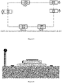
- the figure 1 schematically illustrates an overview of the substrate transport device according to the present invention.
- said conveyor comprising a fixed rail which forms a closed transport loop (a rectangle with rounded corners in the figure); carriages (three carriages in the figure) which hold the substrates (three rectangular substrates per carriage) in an immobile position (flat in the figure) and which move on said rail while transporting the substrates; the central fixed rail as well as the channel of magnets positioned in its center; the fixed base (the length of which is slightly less than a length of the side of the rectangle forming the transport loop in this illustration); as well as a simplified view of the electrically conductive rails which, in this configuration, form a closed loop (of the same shape as the transport loop) of greater length than that of the fixed rail because it is located outside the loop formed by the rail.
- the processing stations have not been shown; purely by way of illustration, the positioning of the printing stations along this transport loop will
- the picture 2 schematically illustrates a view of the secondary assembly which consists of a track of magnets (also called magnetic track), said track being in this illustration fixed to the fixed rail.
- a track of magnets also called magnetic track
- the picture 3 schematically illustrates an overview of the device for transporting substrates in a printing machine comprising several processing stations according to the present invention.
- the “Alphajet” block located at the top left of the figure and positioned in this configuration inside the loop corresponds to the printing and drying stations; in particular in this configuration a combination in series of a printing of conventional inks, of a printing of inks adapted to printed electronics (such as conductive inks based or not of nanoparticles) and an impression of varnish and/or functional inks and/or insulating inks.
- a characteristic of a preferred variant of the present invention is therefore the use of a substrate conveyor (preferably of the carousel type) making it possible to guide and move the substrates through the processing stations, the said conveyor comprising carriages which maintain the substrates in a stationary position (eg flat) and which move along the transport path (eg on a fixed rail) which forms a transport loop, for example a closed transport loop.
- the shape of the transport loop may be of any suitable type. Its length will itself be determined according to the number of processing stations included in the printing machine.
- the printing machine comprises at least one printing station without contact with the substrate (for example two, three, four or more printing stations) and at least one drying station (for example two, three, four or more drying stations);
- the printing station can advantageously be selected from a conventional ink jet printing station (black, white, mono and/or polychrome) and/or a varnish jet printing station, and/or a inkjet printing station suitable for printed electronics (for example conductive ink based or not on nanoparticles), and/or an inkjet printing station suitable for three-part printing dimensions and/or a various and varied inkjet printing station such as for example functional inks and/or insulating inks (for example insulating inks used downstream of an ink printing for printed electronics );
- the drying station can advantageously be selected from an infrared (IR) drying station and/or a near-infrared (NIR) drying station and/or a heated air current drying station, and/or a ultraviolet (UV) lamp drying station and/or UV
- pretreatment stations such as, for example, a corona treatment station, and/or a plasma treatment station, and/or a strip cleaning system (cleaning roller , brush, etc.), and/or a coating station (flexography, etc.), and/or a sheet turning system; and/or the optional use of one or more post-processing (or finishing) stations such as a sheet turning system and/or a coating station (for example by depositing an additional coating, for example gilding or other material) on the substrate, for example by means of a "gilding" depositing device, for example by applying/pressing a sheet (bearing said coating or gilding) on selected areas of the substrate (for example comprising a deposit of adhesive according to a predetermined pattern) so as to cause the desired part of the gilding-type sheet to adhere to the selected areas.
- pretreatment stations such as, for example, a corona treatment station, and/or a plasma treatment station, and/or a strip cleaning system (cleaning roller
- the present invention thus makes it possible to convey substrates of various dimensions/sizes between all the processing stations while meeting the requirements related to the speeds (whether they are different or identical) required during the passages of the substrates in each of the processing stations. as well as at sufficient manufacturing rates to allow an efficient and profitable industrial application.
- the motorization technology in particular the linear motorization technology, used for the transport of the substrates makes it possible to individually control the speed of each carriage; this thus makes it possible, on request, to accelerate or decelerate the speed of a carriage, or even to modify the relative speed of a carriage with respect to another carriage.
- the speed of at least one carriage (for transporting the substrates) moving along the transport loop is different from the speed of a another carriage (for transporting the substrates) moving along the transport loop; for example, the speed of at least one moving substrate transport carriage through a processing station is different from the speed of a moving substrate transport carriage either through another processing station transport loop or through other sections of the transport loop.
- This possibility of individually controlling the speed and/or the acceleration and/or the deceleration of each carriage during its movement along the transport path represents an exceptional advantage according to the present invention.
- This makes it possible to take full advantage of the performance of each of the treatment stations by adapting the speed of the trolley to the type of treatment desired.
- this The invention therefore also makes it possible to carry out printing and/or drying and/or various treatments with variable pitch.
- the transport loop does not include a right angle; on the contrary, its shape will preferably be selected so as to comprise only linear straight parts joined by means of free-form curves (“arcs”).
- the carriages do not perform curves (bends) during their movement and the loop comprises at least one rail (for example 2 parallel rails) located at a certain height and at least one rail (for example 2 rails parallel) perpendicular(s) to the first rail and located at another height which involve the use of a system allowing the carriage to be raised and/or lowered (such as an elevator) to pass from one rail to the other.
- the carriages do not perform curves (bends) during their movement and the loop comprises at least one rail (for example 2 parallel rails) located at a certain height and at least one rail (for example 2 rails parallel) perpendicular(s) to the first rail and located at another height which involve the use of a system allowing the carriage to be raised and/or lowered (such as an elevator) to pass from one rail to the other.
- the transport loop is square or rectangular in shape with rounded corners.
- the processing stations for example the printing and/or drying stations are located in a straight linear part of the transport loop.
- the usual direction of rotation of the carriages along the transport loop is generally defined according to the arrangement of the printing and/or drying stations and/or other substrate treatment station(s). It can therefore be clockwise or counterclockwise.
- Another advantage of the linear motor technology according to the present invention is that the direction of rotation can be reversed if necessary.
- the carriage and the substrate(s) maintained in an immobile position (for example flat) on the carriage can move in both directions along the along the transport path, for example in both directions of rotation on the transport loop.
- This feature allows for example to perform more than one pass through a printing station and/or a drying station and/or another substrate treatment station, and/or in a combination of two or more or all these aforementioned positions.
- a processing station may require repeated passage of the substrate so as to achieve the desired printing resolution (for a printing station) and/or the desired drying quality (for example for a of drying which one would not like to increase the drying power) and/or having to perform multi-passes when other treatment stations will not need it.
- Controlling the movements of the carriages autonomously therefore constitutes a considerable advantage of the present invention.
- the trolley is therefore a trolley that can be qualified as an intelligent and/or autonomous trolley as described in the present description.
- the substrates perform on their selected carriage only one passage along the transport path, for example only around the transport loop, from their holding in a stationary position (for example flat) on the carriage near the input magazine and storage of the substrates up to their point of removal from the same trolley near the output magazine and storage of the treated substrates.
- the substrate can make more than one pass through a printing station and/or a drying station and/or another substrate treatment station, and/or in a combination two or more or all of the aforementioned positions, without leaving his cart.
- This feature can be particularly useful when a printing station and/or a drying station and/or another substrate processing station does not achieve the required performance, for example in terms of resolution of the printed image for a printing station; thus, a second passage under the substation with lower performance will make it possible to solve the problem identified without having to urgently change the faulty substation.
- a preferred characteristic of an alternative embodiment of the present invention is therefore the use of a substrate conveyor (preferably of the carousel type) making it possible to guide and move the substrates through the processing stations, the said conveyor comprising a or more carriages which hold the substrates in a stationary position (eg flat) and which move on a fixed rail along the transport path (eg along the transport loop) during substrate treatments, and characterized in that at least part of the rail is fixed to a base, the surface of which is preferably flat; the length of the fixed rail preferably being identical to that of the transport path (for example of the transport loop).
- the figure 6 schematically illustrates this base - rail assembly.
- a granite plinth which constitutes the base in dark gray on which a fixed rail with double V-guide is fixed; there is an optional holding piece which is fixed on the fixed rail, on which are fixed - on its left a ruler which will be described in the description below - and on its top, the magnet track already described below -before.
- This figure 6 also very schematically illustrates elements which will be described in more detail in the description below, namely, on either side of the fixed rail slides fixed to the base and at the left end of the figure a set electrically conductive rails surmounted by a radiating data (information) transfer cable.
- the dimensions of the base will be selected according to the needs and applications.
- the upper flat surface of the base will be placed at a height from the ground of between 50 cm and 80 cm and will have a transverse width of between 40 cm and 120 cm, for example between 60 cm and 100 cm, and a length between 200 cm and 1200 cm, for example 500 cm and 800 cm.
- the total length of the base(s) of the transport device is selected so as to cover the entire space located below the printing stations of the transportation. More particularly, if the value of the total length of the printing stations is X, the total length of the base(s) of the transport device will be at least X, so as to guarantee the desired flatness under the stations printing; however, as this (these) base(s) represent a significant weight and financial investment, it will be preferred to limit their total length to values less than 3 times X, preferably less than 2 times X, for example less than 1.5 times X, see less than 1.2 times X.
- the total length of the base(s) of the transport device is also selected so as to cover the entire space located below the drying stations of the loop of transportation. More particularly, if the value of the total length of the drying stations is Y and the value of the total length of the printing stations is X, the total length of the base(s) of the transport device will be at least minus (X+Y), so as to guarantee the desired flatness under the drying and printing stations; however, as these base(s) represent a significant weight and financial investment, it is preferable to limit their total length to values less than 3 times (X+Y), preferably less than 2 times (X+Y) , for example less than 1.5 times (X+Y), or even less than 1.2 times (X+Y).
- the total length of the base(s) of the transport device is also selected so as to cover all the space located below the other processing stations (the stations which are neither printing nor drying) of the transport loop such as, by way of illustration, the pre- and/or post-treatment stations.
- the total length of the base(s) of the transport device will be at least (X+Y+Z), so as to guarantee the desired flatness under all the drying, printing and other treatment stations; however, as these base(s) represent a significant weight and financial investment, it is preferable to limit their total length to values less than 3 times (X+Y+Z), of preferably less than 2 times (X+Y+Z), for example less than 1.5 times (X+Y+Z), or even less than 1.2 times (X+Y+Z).
- the total length of the base(s) of the transport device is less than half the length of the transport path (for example of the transport loop), less than 0 .4 times the length of the transport path (for example of the transport loop), for example less than a third of the length of the transport path (for example of the transport loop).
- one, two or more pedestals will be placed in the transport device.
- the plinth provides the stable base/solid foundation for the carriage (and/or rail) along the transport path (e.g. along the transport loop) at the most critical locations such as under workstations. impression.
- the Applicant has found that the base makes it possible to effectively solve the vibration problems encountered with the transport devices of the prior art, which therefore makes it possible to improve the transport of printable and/or printed substrates on the whole processing stations included in a printing machine, in particular a printing machine without contact with the substrate, such as ink-jet printing machines.
- polishable firm rock such as granite, and/or basalt, and/or porphyry, and/or serpentinite, ... and/or gneiss, and /or sandstones, and/or breccias, and/or limestones and/or other conglomerates, as constituent element(s) of a base used in a preferred embodiment variant according to the present invention.
- the weight ratios between the base, the carriage and the substrate(s) also constitute important characteristics making it possible to combat the vibrations of the transport device; thus, in an alternative embodiment of the present invention, the ratio between the weight of a carriage of length L and the weight of a length L of the base will be less than 0.3, for example less than 0.2; in an alternative embodiment of the present invention, the ratio between the weight [of a carriage of length L and the substrates arranged on said carriage] and the weight of a length L of the base will be less than 0.3, by example less than 0.2.
- the system for guiding the carriages on the rail is selected from V-shaped guiding systems; preferably comprising a double V-guide as illustrated in the figure 6 (rail whose ends are in a “male” V) and the figure 7 (“female” V-wheels fixed to the trolley).
- the trolley comprises at least one V-wheel, preferably 2 V-wheels, more particularly at least 4 V-wheels.
- the system for guiding the carriage on the rail comprises at least one pair of guiding elements arranged on either side of the rail (for example wheels); each pair of guide elements (for example pair of wheels) comprising a mechanism ensuring the guidance of the carriage both in straight lines and in bends.
- each pair of guide elements will comprise a retaining bar which connects the two guide elements to each other (for example the two wheels to each other), the said retaining bar comprising a pivoting axis connected to the carriage making it possible to ensure optimum guidance of the carriage along the rail and, in particular along the bends formed by the transport loop.
- the system for guiding the carriage on the rail comprises 3 guiding elements (for example 3 wheels), 2 on one side of the rail and 1 on the other side of the rail so as to allow the trolley to take the turns formed by the transport loop and also to follow linear directions.
- the figure 7 therefore illustrates a variant of a carriage according to the present invention, said carriage comprising a structural base shown in light gray in the figure surmounted by a table (in dark gray) for supporting the substrates which will be detailed below in the description; you can also see under the base 2 V-shaped wheels surrounded by two sliders which will be detailed below in the description and, to the left of the base, a sliding contact element (used to supply energy to the trolley).
- a variant of the figure 7 (not shown) will be to arrange the wheels in a V such that they surround the runners of the slides, which will preferably imply that the rails of the slides will be positioned on the fixed rail and that the height of the sliders of the slides will be lower than that of the V-wheels under the base of the trolley.
- the trolley guidance system therefore comprises at least one rail coupled to the wheel(s) of the trolley according to a V-shaped guide device; this makes it possible to guide the wheel(s) of the trolley in the V(s) of the rail; preferably a rail with double V-guide, which allows the V-wheels of the trolley to be guided therein.
- the carriage is provided with 4 V-shaped wheels placed (preferably symmetrically two by two with respect to the center of the carriage), two of the wheels being guided by the V d one side of the rail and the other two wheels being guided by the V on the other side of the rail.
- the rail is positioned centrally with respect to the width of the carriage and/or the width of the base; thus, in an alternative embodiment of the present invention, the center of the width of the rail is at a distance of less than 20 cm, for example less than 15 cm from the center of the width of the carriage and/or from the center of the base width. In a particular embodiment of the present invention, the center of the width of the magnet track is aligned with the center of the width of the fixed rail.
- At least part of the rail is fixed to a base or forms an integral part of said base.
- a base over the entire length of the rail for its attachment.
- a hollow rigid structure is used for fixing the rail (or for integrating the rail into said structure) outside the printing stations and/or the drying stations and /or any other substrate processing station.
- the total length of the hollow rigid structure used for fixing the rail of the transport device is greater than or equal to half the length of the transport path (for example of the loop transport), greater than or equal to 0.6 times the length of said path (of the transport loop), for example greater than or equal to two thirds of said path (of the length of the transport loop).
- the transport device is equipped with at least one displacement detection system (or sensor), preferably a linear displacement detection system (or sensor), for measuring the displacement (position, speed, acceleration and/or deceleration) of the carriage along the transport path, for example relative to the fixed rail.
- a displacement detection system or sensor
- Any displacement detection system (or sensor) satisfying the required accuracy requirements can advantageously be used in the device according to the present invention.
- Mention will be made, by way of non-limiting illustration, of a displacement sensor “O” comprising a mobile part and a fixed part, for example an optical ruler.
- the fixed part of the displacement sensor preferably consists of a linear ruler preferably positioned along the transport path (of the transport loop) under printing stations and/or drying stations and/or under any other substrate processing station requiring increased precision in measuring the position, speed, acceleration and/or deceleration of the carriage along the transport path (from the transport loop), preferably under the printing stations.
- This rule preferably linear
- the carriage integrates at least one reader (preferably an optical reader) which constitutes the mobile part of the displacement sensor.
- the figure 1 schematically illustrates an overview of the substrate transport device according to the present invention.
- said conveyor comprising a fixed rail which forms a closed transport loop, and carriages which hold the substrates in an immobile position (for example flat ) and which move on the said rail transporting the substrates, the control of the movement being allowed thanks to the linear rule which, on this figure 1 , is confused with the fixed rail.
- the figure 6 also schematically illustrates the rule which is positioned in this configuration to the left of the optional holding piece which is fixed to the fixed rail.
- the transport device is equipped with at least one displacement detection system (a displacement sensor), preferably a linear displacement sensor, for measuring the displacement (position, speed, acceleration and/or deceleration ) of the trolley in relation to the processing station(s).
- a displacement detection system preferably a linear displacement sensor
- Any displacement sensor satisfying the required precision requirements can advantageously be used in the device according to the present invention. Mention will be made, by way of non-limiting illustration, of a displacement sensor “M” comprising a mobile part and a fixed part, for example a magnetic ruler.
- the movable part of the sensor (“movable” because it moves with the carriage) of displacement (for example of the magnetic sensor) preferably consists of a rule, preferably linear, fixed on the carriage, for example fixed along a longitudinal axis (that is to say parallel to the direction of movement of the carriage) on the carriage (or forming an integral part of the carriage).
- the presence of the rule, preferably linear thus makes it possible to determine at any time the positioning, the speed, the acceleration and/or the deceleration of the carriages along the transport path (for example on the transport loop) with respect to at the processing station(s).
- at least one processing station preferably at least one printing station, preferably all the stations printing, or even all processing stations, incorporate at least one reader (preferably a magnetic reader) which constitutes the fixed part of the displacement sensor.
- the transport device is equipped with at least one "O" displacement sensor to measure the displacement of the carriage relative to the transport path (for example the rail) and at least displacement sensor "M” for measuring the displacement of the carriage relative to the processing station.
- the "O" sensor reader and the "M” sensor ruler are located on the carriage.
- the rule of the "O" sensor is an integral part of the rail and/or is fixed to the rail and/or is fixed to the base of the rail and/or is an integral part of the base. of the rail and/or is attached to the rail structure and/or is an integral part of the rail structure.
- the reader of the "M” sensor is fixed to a fixed (or mobile) element of a printing station and/or of a drying station and/or of another processing station.
- the “O” sensor is an optical linear displacement sensor and the “M” sensor is a magnetic linear displacement sensor.
- the Applicant has discovered, thanks to the combination of these two displacement sensors, that it is possible to achieve an exceptional level of measurement precision (for example of the order of a micrometer on the critical sections of the transport loop, for example of the order of a micrometer over transport loop lengths of the order of a meter) thus allowing optimized management of the management of the positioning and/or the speed and/or the acceleration and/or the deceleration of the carriages along the transport path, for example along the transport loop.
- the dual positioning management of the readers/sensors as described above also brings other essential advantages to the present invention as described below.
- the fact of arranging the reader of the "O" sensor on the carriage makes it possible to avoid any problem of transmission of the information measured between the reader and the active elements of the carriage, for example the control of the primary motor assembly the linear motorization of the mobile carriage; this control reactivity makes it possible to improve the intelligent and/or autonomous character of the truck because it makes it possible to minimize the delays between the measurement and the corresponding induced action.
- the fact of arranging the ruler of the "M” sensor on the carriage and therefore the corresponding reader of the "M” sensor on a fixed element (or mobile) of a processing station makes it possible to avoid any problem of transmission of the information measured between the reader and the active elements of the processing station (for example of a printing station (for example the print heads of said printing station) and/or drying and/or other treatment) along the transport path.
- a processing station for example a printing station and/or a drying station and/or another processing station
- This responsiveness allows the said station(s) to act without delay according to the measure taken because it makes it possible to minimize the delays between the measure and the corresponding induced action; this responsiveness also makes it possible to avoid having a system for exchanging information between the carriage and the processing station to obtain this positioning information, which also reduces costs.
- the double positioning management makes it possible to adjust the measurement elements to the need(s) of the carriage(s) and the processing station(s) (for example, a printing station ). Indeed, the Applicant has found that the measurement accuracy, and more particularly the knowledge of the positioning of the moving part (for example, the carriage), can be different between the carriage(s) and the station(s). treatment.
- the measurement accuracy between "O" sensor and "M” sensor may be different (lower or higher) or equal.
- the sensors can be chosen according to the needs of the processing station (or trolley) and can therefore be different from one workstation (or trolley) to another. This also enables cost reduction. Indeed, as it is possible to adjust the measurement system to the needs of the trolley(s) and the treatment station(s), the cost of the necessary parts is optimized.
- the transport device also comprises at least one slide, for example a slide arranged on each side of the fixed rail which is preferably central.
- the figure 2 , 6 and 7 schematically illustrate the components of these guide rails which, in this illustration and this embodiment, consist of rails and guide elements (eg guide shoes) fixed to the carriage; in the figure 2 and 6 , the rails of the two slides are fixed to the base and located on either side of the fixed rail; in the figure 7 , the pads of the slides are arranged under the base of the carriage and they surround the V-shaped wheels of the guidance system.
- guide rails which, in this illustration and this embodiment, consist of rails and guide elements (eg guide shoes) fixed to the carriage; in the figure 2 and 6 , the rails of the two slides are fixed to the base and located on either side of the fixed rail; in the figure 7 , the pads of the slides are arranged under the base of the carriage and they surround the V-shaped wheels of the guidance system.
- a variant of the figure 7 will be to arrange the wheels in a V so that they surround the pads slides, which will preferably imply that the slide rails will be positioned on the fixed rail and that the height of the slide shoes will be lower than that of the V-wheels under the base of the trolley; in this configuration, the use of a single rail for the slide is possible even if this does not constitute a preferred variant according to the present invention.
- the slide comprises a rail, preferably two rails located on each side of the rail (preferably central), which are either fixed to the base or form an integral part of said base.
- the slide comprises a rail, preferably two rails which either form an integral part of the fixed rail (preferably central) and/or are fixed to the fixed rail (preferably central) and/or are fixed to the base of the fixed rail (preferably central) and/or form an integral part of the base of the fixed rail (preferably central) and/or are fixed to the structure of the fixed rail (preferably central) and/or form part integral to the structure of the fixed rail (preferably central).
- the slide is smooth and preferably comprises on the carriage one or more guiding elements (for example "female" elements), preferably at least two, for example at least 4 (as shown in figure 7 ), for example sliding skates.
- guiding elements for example "female" elements
- the slider is a dovetail slider.
- the Applicant believes that the use of the central rail and its guiding in combination with the aforementioned slide not only makes it possible to satisfy the requirements of precise movement of the carriage along the transport path (for example of the transport loop) but also to allow optimized movement during curves of the transport path (of the transport loop).
- the length of the rail(s) of the slide(s) may be identical to the length of the fixed rail or of the transport path (of the transport loop).
- the total length of this slide rail(s) will preferably be less than that of the fixed rail because it is preferable not to put any in the curves/bends formed by the transport path (the transport loop); we will speak of the total length of rail per slide, because said rail of a slide may in fact be made up of several pieces of rail along the path (of the loop) of transport.
- the total length of the rail of a slide of the transport device is selected so as to cover all the space located below the printing stations of the path (of the loop ) transport. More particularly, if the value of the total length of the printing stations is X, the total length of the rail of a slide of the transport device will be at least X, so as to guarantee the desired flatness under the printing stations. impression and the requirements for precise movement of the carriage along the transport loop. However, as the presence of this slide rail is not essential outside the printing stations, the total length of the rail of a slide of the transport device will for example be limited to values less than 3 times X, of preferably less than 2 times X, for example less than 1.5 times X, or even less than 1.2 times X.
- the total length of the rail of a slideway of the transport device is less than the sum of the lengths of the linear parts of the transport path (for example of the transport loop), for example less half the length of the transport path and/or the transport loop, less than 0.4 times the length of the transport path and/or the transport loop, for example less than a third of the length of the path transport and/or the transport loop.
- the width of the initial end (the entrance in the direction of travel of the carriage) and/or the width of the final end (the exit in the direction of movement of the carriage) of said rail will advantageously be less the average width of said rail; without wishing to be limited by this explanation, the Applicant believes that this makes it possible to ensure optimal insertion (and/or exit) of the guide element (for example of the pad(s)) in the rail while limiting mechanical wear , premature degradation of the rails as well as vibration phenomena which may interfere with the objectives of the present invention.
- a V-shaped inlet and/or an inverted-V-shaped outlet for the rail of a slide of the transport device mention will be made of a V-shaped inlet and/or an inverted-V-shaped outlet for the rail of a slide of the transport device.
- a characteristic of the present invention is therefore the use of a substrate conveyor, preferably of the carousel type, making it possible to guide and move the substrates through the processing stations, the said conveyor comprising at least one, preferably several carriages which hold the substrates in a stationary position (for example flat) and which move along the transport path (for example on a fixed rail which makes it possible to move each carriage/substrate assembly on the rail) and being characterized in that the said carriage comprises a table, preferably a suction table, for maintaining the substrate in a stationary position (for example flat) relative to the table along the transport loop during the processing of the substrate.
- the figure 7 illustratively represents the carriage and some of its components, for example, a substrate holding table, the V-wheels of the guidance system as well as the pads of the slides, a sliding (electrical) contact element.
- the dimensions of carts and tables will be selected according to the needs and applications while taking into account the factors of space, weight and machining.
- the carriage is equipped with an identification means allowing "personalization" when the carriage thus identified passes through any station of the device according to the present invention.
- the present invention may use any identification technology, preferably contactless, for trolleys.
- this means of identification may advantageously be selected from among RFID technologies (Radio Frequency Identification - technology for identifying objects making it possible to store and retrieve data remotely using markers called “radio-tags (or “tag” or “transponder”), barcodes, and/or any other technology based on a recognition principle, for example an optical transmitter/receiver.
- RFID technologies Radio Frequency Identification - technology for identifying objects making it possible to store and retrieve data remotely using markers called “radio-tags (or “tag” or “transponder”), barcodes, and/or any other technology based on a recognition principle, for example an optical transmitter/receiver.
- the maintenance carriage can be identified (for example the "inkjet head cleaning" carriage inserted in the stream of mobile carriages) and thus prevent it from being subjected to any processing. concerning the substrates and this, also including the absence of loading and/or unloading of substrate on this maintenance trolley.
- any type of table with a preferably flat upper surface and any system for maintaining the substrate in a stationary position (for example flat) on said table can advantageously be used.
- the holding force exerted by the system for holding said substrate in the immobile position on the table will be greater than any other force which could cause the displacement of the substrate during the treatments of the said substrate and/or during movement of the carriage.
- means for gripping or pressing the substrate for example clamps and/or clamping strips.
- the dimensions of the table will therefore preferably meet the following criteria: a transverse dimension (that is to say perpendicular to the longitudinal axis in the plane of the transport path) at the least equivalent to the transverse dimension of the largest substrate used - and a longitudinal dimension at least equivalent to the longitudinal dimension of the largest substrate used; an additional advantage of the present invention is that several substrates (identical or different) can be maintained in an immobile position (for example flat) on the table, which demonstrates the exceptional flexibility provided by the device according to the present invention.
- the top layer of the carriage shown in the figure 7 is a simplified schematic representation of the entire holding table (front view). A representation of three identical substrates held in a stationary position on a holding table is described for illustrative purposes in the figure 8 (top view).
- a characteristic of a particular and preferred embodiment of the present invention is therefore the use as a holding table of a suction table which is part of the transport carriage and which makes it possible to hold the substrates in a stationary position (for flat example) along the transport loop.
- Downdraft tables and their operation are well known to those skilled in the art and the latter can therefore easily use a downdraft table suitable for the present invention.
- the construction and dimensions of the downdraft table are not critical provided that it fulfills its role of maintaining the substrate in an immobile position (for example flat) well.
- the force for maintaining the stationary position of said substrate on the vacuum table will be greater than any other force which could cause the displacement of the substrate during the treatments of said substrate and/or when moving the carriage; by way of illustration and not limitation, we will cite the case of the influence that drying with a stream of heated air could have on the position of the substrate on the vacuum table, an influence which must therefore be annihilated thanks to the holding force of the table aspirant.
- downdraft floor which is usually made mainly of metal and/or polytetrafluoroethylene (also known as Teflon) pierced with multitudes of holes allowing the table to exert suction and therefore the maintenance thanks to this suction force of the substrate on the sole.
- Teflon polytetrafluoroethylene
- a hearth of the type described above is not used as illustrated below in the description of the figures.
- downdraft tables usually consists of an active suction area (active suction assembly).
- active suction assembly active suction assembly
- Downdraft tables and their operation are well known to those skilled in the art and the latter can therefore easily use a downdraft table comprising an active suction zone suitable for the present invention, namely an active suction zone sufficiently powerful to be able to hold the substrate in a stationary position (e.g. flat) on the vacuum table.
- an active area of active suction is represented in the figure 9 where it can be seen that the active suction zone comprises five suctions (represented in the figure by fans) which are preferably individually adjustable.
- a major objective of the present invention is to prevent the components of the transport device from interfering with the efficiency requirements of each of the printing and/or processing stations.
- control for example by variation of the suction power
- individual control of the suction elements constituting the active suction area (of the active suction assembly).
- the compartmentalized active suction assembly (the active suction zone) will comprise at least two, preferably at least three, preferably at least four, for example at least least five suction elements whose power is controllable, preferably individually.
- a representation of five suction elements (5 fans) is described for illustrative purposes in the figure 9 (view from below).
- the assembly constituted by the active suction zone is therefore an essential component of the suction table, said active suction assembly preferably constituting the lower layer of the table.
- this active suction assembly will be attached to the passive layer located directly above, for example by means of clips; by way of illustration, this active suction assembly may be integrated into a frame which will be preferably attached to the passive layer directly above, for example by means of clips. In another alternative embodiment according to the present invention, this active suction assembly will be attached to the base of the cart or to an intermediate element itself attached to the base of the cart.
- the downdraft table also comprises a structural layer with chambers (passive suction zone/passive suction assembly), located above the active suction zone (between the active suction area and the substrate), which helps to compartmentalize the suction flows.
- This structural layer is preferably rigid or semi-rigid.
- this structural layer comprises Ch chambers (or Ch compartments), which are preferably arranged opposite the compartments of the suction zone, in order to improve the control of the power and/or the homogenization of suction within the chambers.
- this structural layer chambers (passive suction zone/passive suction assembly) will be selected according to the needs and applications; the widths/lengths of this structural layer (for example a rectangular parallelepiped-shaped frame of height “h”) will preferably coincide with those of the active suction layer; the heights of this layer (and therefore, preferably, also of the chambers) are not critical provided that the layer fulfills its role of homogenization and/or control of the suction power of the downdraft table; by way of illustration and not limitation, we will cite a height “h” of this structural layer (and therefore, preferably, also of the chambers) of between 10 and 50 mm, for example between 15 and 30 mm, for example of 20 mm.
- This structural layer will advantageously comprise at least two, preferably at least three, preferably at least four, for example at least five chambers.
- the number of chambers may advantageously correspond to the number of compartments of the active suction zone.
- the structural layer will be removable (for example by means of clips) and can therefore be replaced as needed; this will make it possible to use a number of chambers appropriate to the substrates and/or to the treatments used without having to change the compartmentalized active suction zone.
- the number of chambers will remain less than 20, preferably less than 10, so as to avoid clutter that could interfere with the performance of the suction area.
- a passive suction zone is represented in the figure 10 where we can see that the passive suction zone comprises five chambers (represented in the figure by rectangles - top view); clips can also be seen on the four sides of this frame.
- the holding table is a suction table which comprises an active suction assembly compartmentalized into two or more suction elements (for example 3, 4, 5, or more ) surmounted by a passive suction assembly divided into two or more chambers (for example 3, 4, 5, or more), characterized in that, preferably, the number and arrangement of the chambers coincide with the suction elements .
- the surface of the upper part of the chambers will consist of grid(s) whose role will be twofold: these grids will not only make it possible to confer on the upper part of the passive suction assembly a flat surface which will thus improve the flat positioning of the next layer and also help to distribute the suction flows well within each chamber.
- a chamber will advantageously comprise on its upper surface at least five, preferably at least ten, for example at least 15 surface sub-chambers delimited by the meshes of the grid.
- the figure 11 describes a structural layer (passive suction zone/passive suction assembly) which comprises 5 chambers, 3 chambers each comprising 24 surface sub-chambers and 2 chambers each comprising 18 surface sub-chambers.
- the chambered structural layer also comprises additional elements for homogenizing the suction, elements preferably located at the places where the Positioning of the fans may cause suction peaks and/or vortices which could interfere with the proper functioning of the treatment stations.
- the figure 11 illustrates a structural layer (passive suction zone/passive suction assembly) that includes 5 additional elements suction homogenization (in the form of pellets) which are located opposite the center of the suction elements of the active suction zone, which makes it possible to overcome any vortex effect and/or suction peak that said suction elements could generate.
- the downdraft table comprises an active suction assembly (active suction zone) as defined above in combination with a passive suction assembly (active suction zone).
- passive suction as defined above so as to control the suction power of the table according to the positioning of the substrates; by way of illustration, this not only makes it possible to better balance the suction whatever the position and size of the substrates, but also to be able to limit the suction in specific delicate zones such as when the trolley passes by below the printheads.
- a system making it possible to vary the height and/or the orientation and/or a translation/rotation of the holding table (preferably the suction table) is integrated into the carriage, by example a motorization system and/or actuator(s).
- This additional system (for example this motorization and/or these jacks) can prove to be extremely useful, for example, to compensate for faulty printing nozzles and/or to increase the resolution of the prints and/or to guarantee optimal positioning of the substrates under the processing stations.
- a rotation and/or a translation of the table allowing the use of a nozzle to replace a faulty nozzle for carrying out the printing at a precise location on the substrate.
- a micrometric (transverse) motorization will be used for this type of motorization; the displacements can therefore advantageously achieve a precision of the order of a micron and will preferably be restricted to maximum values equivalent to one cm in the three dimensions of space.
- the figure 7 illustrates the presence of this element comprising an additional motorization; we can indeed see a trolley comprising a structural base shown in light gray in the figure surmounted by a support table (in dark gray) and also an intermediate piece between the table and the base constituting this element of additional motorization, for example a micrometric motorization allowing the movement of the table in a direction perpendicular to the direction of movement of the carriage.
- a trolley comprising a structural base shown in light gray in the figure surmounted by a support table (in dark gray) and also an intermediate piece between the table and the base constituting this element of additional motorization, for example a micrometric motorization allowing the movement of the table in a direction perpendicular to the direction of movement of the carriage.
- the device and method claimed differ from the prior art thanks to their flexibility of use and thanks to a reduction in manufacturing times as well as in the corresponding costs, this which makes them particularly attractive, in particular for printed electronics, for example for the manufacture of printed circuits.
- the present invention as well as its claimed downdraft table, with its characteristics as described, of which we will cite by way of example the honeycomb structural layer, the optional trellis and the absence of soles with a multitude of holes, provide very important advantages in the field of printing for printed electronics.
- the Applicant has observed a major improvement in the quality and precision of the printing because the vacuum table has a double beneficial action not only on the printing but also on the drying of the printed ink, which opens up fields new to the present invention such as printed electronics and, in particular, printed electronics of radio frequency identification (RFID) tags with or without a chip (also called RFID tags or RFID tags without a chip); without wishing to be limited by this explanation, the Applicant believes that during the drying of printed electronics, for example during infrared (IR) and/or near-infrared (NIR) treatment, the localized effect of the treatment combined with the effect of heat dissipation through the table allows better annealing of the ink which can, for example, result in improved conductivity.
- IR infrared
- NIR near-infrared
- the vacuum table also makes it possible to best adapt (depending on the substrate and the printing/deposition) the power and speed of drying.
- the vacuum table allows the heat to be dissipated, which limits the deformations of certain substrates, or even does not have any repercussions between the different treatment stations (for example, infrared (IR) drying with ultraviolet drying (UV)).
- IR infrared
- UV ultraviolet drying
- the honeycomb structural layer has a thickness "e" of between 1 and 100 mm, for example between 5 and 30 mm, preferably between 5 and 15 mm, for example 8 mm; cell size (e.g. alveoli) is included between 10 microns and 10 mm, for example between 1 and 8 mm, preferably between 2 and 5 mm, for example 3.6 mm; the thickness of the cell walls (for example cells) is between 0.5 micron and 5 mm, for example between 10 and 200 microns, preferably between 30 and 100 microns, for example 50 ⁇ m.
- cell size e.g. alveoli
- the thickness of the cell walls is between 0.5 micron and 5 mm, for example between 10 and 200 microns, preferably between 30 and 100 microns, for example 50 ⁇ m.
- the structural honeycomb layer is of regular hexagonal tiling as illustrated in the figure 12 ; it therefore consists of right prisms with a hexagonal base (which therefore preferably do not include holes in their vertical walls).
- the surface dimensions of the structural honeycomb layer will be selected according to the needs and applications and will preferably correspond at least to the surface of the substrate (or substrates if there are several held on the same table) ; we will cite, by way of illustration, dimensions (W/L) in mm of the order of 760/1070.
- the widths/lengths of this structural honeycomb layer e.g. a rectangular parallelepiped-shaped frame of height corresponding to the thickness "e" mentioned above
- the table (preferably the downdraft table) comprises a honeycomb structural layer as defined above.
- the use of this honeycomb structural layer in the table (preferably the downdraft table) has solved other fundamental problems encountered in prior art devices. Indeed, inkjet printing techniques (whether through a conventional or special ink printing station (for example conductive) and/or a varnish printing station) require often rapid drying of the ink (or of the varnish), which explains why at least one drying station directly follows a printing station along the substrate transport path. This close arrangement is unfortunately not compatible with the proper functioning of the print heads because close drying risks impacting the performance of said heads, for example by a blocking effect of the print nozzles due to the untimely solidification of the ink in these nozzles.
- the Applicant believes that the use of a structural honeycomb layer (as described above) allows optimal dissipation of the heat generated by the drying station as well as a drastic reduction in thermal reflection and transfer phenomena in the table and/or from the table to the print heads; by way of illustration and not limitation, the Applicant believes that the use of a honeycomb structural layer (as described above) makes it possible, for example, to trap UV radiation from drying so that it does not interfere ( by reflection) with the proper functioning of the print heads and therefore do not cause the ink to harden within the print nozzles.
- the use of a honeycomb structural layer makes it possible to dispense with the suction soles of the prior art such as by example those described above (soles usually made mainly of metal and/or polytetrafluoroethylene (also known as Teflon) and pierced with multitudes of holes); in fact, the honeycomb structural layer (as described above) can directly serve as a holding sole for the substrates and thus allow the table to exert suction and therefore the holding of said substrates on this sole .
- the structural honeycomb layer is removably fixed on the table, which allows it to be replaced and/or changed depending, for example, on the types of substrates. used.
- Any removable fastening system can advantageously be used; we will cite by way of illustration a fastener of the toggle type and/or of the clip-on type.
- the honeycomb structural layer is made of aluminum; it is obvious that the person skilled in the art will be able to select other materials, similar or not to aluminum, which will also meet the requirements of the present invention, for example steel and/or any suitable plastic and/or composite and/or ceramic material.
- the structural honeycomb layer is not sandwiched, that is to say does not comprise a lower and/or upper sub-layer; this variant is preferred in the case of a downdraft table so as not to disturb the suction through the cells (for example cells).
- the table (preferably the vacuum table) comprises a structural layer consisting of a lattice for holding the substrates.
- this mesh can advantageously be used for low-weight substrates; which makes it possible to avoid any possible “marking” of said substrates during their immobilization on the table.
- the Applicant believes that the use of a mesh for maintaining the substrates also makes it possible to freeze and maintain the honeycomb layer in its original shape while, in the variant of use of a downdraft table, guaranteeing and improving the homogenization of the aspiration.
- a support trellis is illustrated in the figure 13 .
- a grid made of stainless steel and/or ceramic fiber can advantageously be used as a trellis. It is obvious that those skilled in the art will be able to select other materials, similar or not to stainless steel and/or to ceramic fibers, which will also meet the requirements of the present invention.
- the mesh of the trellis will be selected from the fine meshes to avoid a textural of the printed paper.
- the dimensions of a mesh of the lattice will be less than half the size of the cell of the honeycomb, for example less than a quarter of the size of the cell of the honeycomb.
- the surface dimensions of the lattice structural layer will be selected according to the needs and applications and will preferably correspond to the surface of the substrate (or substrates if there are several maintained on the same table) increased by a margin of security ; we will cite, by way of illustration, dimensions (W/L) in mm of the order of 760/1070.
- the widths/lengths of this mesh will preferably coincide with those of the structural honeycomb layer, and optionally with those of the passive suction layer, and optionally also with those of the active suction layer.
- the mesh will preferably consist of a network of regular and/or identical meshes.
- the combination of a mesh as defined above fixed on the structural layer of the honeycomb type (as described above) constitutes a preferred embodiment according to the present invention in terms of maintaining the substrates on the table (preferably the downdraft table).
- the use of a structural layer of the honeycomb type (as described above) and of the lattice makes it possible to dispense with the suction soles of the prior art such as for example those described above ( soles usually made mainly of metal and/or polytetrafluoroethylene (also known as Teflon) and pierced with multitudes of holes); in fact, the honeycomb-type structural layer (as described above) on which a mesh is deposited/fixed can directly serve as a retaining sole for the substrates and thus allow the table to exert suction and therefore the maintenance of said substrates on this sole.
- the lattice is removably fixed to the table, which makes it possible to replace it and/or change it depending, for example, types of substrates used.
- Any removable fastening system can advantageously be used; we will cite by way of illustration a fastener of the toggle type and/or of the clip-on type.
- the removable fixing system fixes the mesh directly to the honeycomb layer.
- optional masking zones can be added to the mesh, for example to prevent suction from taking place in zones without substrate.
- the table (preferably the downdraft table) comprises an additional optional layer consisting of a filter which makes it possible to further improve the efficiency of the table by making it possible to trap the radiation while avoiding that they are reflected on the table.
- this filter is an anti-UV filter.
- the surface dimensions of the filter layer will be selected according to the needs and applications and will preferably correspond to the surface of the substrate (or substrates if there are several maintained on the same table) increased by a safety margin ; we will cite by way of illustration dimensions (1/L) in mm of the order of 760/1070.
- the widths/lengths of this filter will preferably coincide with those of the mesh and/or the honeycomb structural layer, and optionally with those of the passive suction layer, and optionally also with those of the suction layer active.
- this filter layer will be placed directly below and/or above the honeycomb layer and/or the mesh.
- the table (preferably the downdraft table) comprises optional additional elements (which we will call flatness underlayer elements) arranged at specific locations between two of the above layers. mentioned allowing the improvement of the homogeneity/flatness of the table supporting the substrate(s).
- This optional additional underlayer will thus level the layers located above and/or below it and make the last layer of the table very flat.
- the figure 7 therefore illustrates a trolley variant according to the present invention, said trolley comprising, a structural base shown in light gray in the figure surmounted by a table (in dark gray) for supporting the substrates, V-shaped wheels under the base (for the V-shaped guide - fixed rail) and slide runners; this figure 7 also schematically illustrates a conductive contact element (sliding electrical contact) which provides the electrical connection between the current rail (described below) and the carriage.
- a conductive contact element sliding electrical contact
- the structure of the carriage comprises at least one protection which makes it possible to avoid damaging the other components of the carriage in the event of an unexpected collision between two carriages.
- This protection will therefore ideally be placed on the front edge or on the rear edge (in the direction of travel) of the carriage or, preferably, on the front and rear edges of the carriage.
- these protections are not essential. However, in order to mitigate the possible risks linked for example to a power outage and/or a failure in the transmission of data (instructions) to the truck, this type of protection will be preferred.
- An optional feature of the substrate transport device of the present invention is therefore the use of a carousel-type substrate conveyor making it possible to guide and move the substrates through the processing stations, the said conveyor comprising carriages which hold the substrates in a stationary position (for example flat) and which move on a fixed rail which forms a transport loop, characterized in that the device comprises a parking lane for the carriages, the said lane being removably connected to the conveyor rail and thus allowing parking and/or to add and/or remove one or more carriages.
- this type of siding is similar to what is used in the railway field, with a switch making it possible to divert certain trains and/or wagons.
- the carriage can be brought by translation perpendicular to the transport loop towards the said siding by any other appropriate device.
- This siding may advantageously constitute a dead end and/or a diversion loop on the transport loop and be located at any appropriate location of the transport loop, with an identical and/or different entry and exit point. on the loop
- An optional feature of the substrate transport device of the present invention is therefore the use of a carousel-type substrate conveyor making it possible to guide and move the substrates through the processing stations, the said conveyor comprising carriages which hold the substrates in a stationary position (for example flat) and which move on a fixed rail which forms a transport loop, characterized in that the device comprises a bypass track for the carriages, the said track being removably connected to the conveyor rail and thus allowing any type of additional treatment of the substrate to be provided.
- a process for turning the substrate over on the table and/or a coating station often called a gilding station (“foil”) as described above in the description; note, however, that these treatments and/or processes could also be unroll on the main transport loop.
- This diversion path could advantageously constitute a diversion loop on the transport loop and be located at any appropriate place of the transport loop, with an identical and/or advantageously different entry and exit point on the loop; for example, for a process of turning over a substrate, a bypass loop could advantageously be arranged between the stations for loading and unloading the substrates.
- the substrate transport device comprises at least one carriage equipped with a diagnostic tray.
- This diagnostic trolley can advantageously be in rest mode on a siding as defined above to then be brought into active mode on the transport loop so as to carry out any diagnostic act making it possible to check the correct operation of the stations. treatment.
- a trolley may comprise both a diagnostic tray and a maintenance tray.
- a feature of the present invention is therefore the use of a substrate conveyor (preferably of the carousel type) making it possible to guide and move the substrates at the through processing stations, the said conveyor comprising carriages which hold the substrates in an immobile position (for example flat) and which move along the transport path (for example on a fixed rail which makes it possible to move each assembly carriage/substrate on the rail).
- a substrate conveyor preferably of the carousel type
- the "printing machine management part” is the part of the claimed device (with the exception of the carriage) allowing the supervision and/or control of various elements of said machine.
- the management part of the printing machine can include the communication part making it possible to exchange information between the various elements of the machine and/or with the carriages.
- this information is orders, instructions, positions, speeds, identifications or any other useful information to be exchanged between the various elements of the machine and/or with the carriages.
- the management part of the printing machine can contain the means for controlling various actuators such as the means for controlling the processing stations.
- the management part can also contain the management of various sensors (for example: sensor arranged on the transport loop and/or in the processing stations, such as the positioning sensor(s).
- the management part can comprise the management of the effectors. An effector finalizes the work; it produces the expected effect.
- the management part can also contain interfaces such as indicators, screen, means of identification and any other means of interfacing. Indeed, the Applicant does not wish to be limited to Man Machine interfaces. It is quite possible to have a Machine Machine interface. By way of non-limiting illustration, a Machine Machine interface can be an element on a processing station (such as a bar code) allowing the trolleys to identify this processing station and to act accordingly. Of course, the Applicant does not wish to be limited solely to these elements mentioned above. It is obvious for those skilled in the art that programmable logic controllers, electronic circuits (which may contain FPGAs, and/or microprocessors), etc. can be included in the management part of the printing machine.
- the substrate transport carriage can therefore move autonomously along the transport path (of the transport loop) thanks to an active motor element ensuring its movement, for example, the linear motor described above (intelligent carriage and/or autonomous).
- This embodiment implies the need to supply the mobile carriage with energy and also to ensure the transfer of information, preferably the two-way transfer of information (of digital information preferences).
- this power supply will be permanent; periods of standby will however be tolerated when the truck is located in an area where it can remain immobile and/or without the need for transferring information.
- the "trolley management part” is the part of the trolley allowing the supervision and/or control of various elements of the trolley.
- the management part of the carriage can include the communication part making it possible to exchange information with the rest of the machine.
- this information is orders, instructions, positions, speeds, identifications or any other useful information to be exchanged between the truck and the rest of the machine.
- the management part of the carriage can contain the means for controlling various actuators such as the means for controlling the primary motor assembly.
- the management part can also contain the management of various sensors (for example: sensor contained in the carriage such as the positioning sensor(s).
- the management part can comprise the management of the effectors. An effector finalizes the work; it produces the expected effect.
- the management part can also contain interfaces such as indicators, screen, means of identification and any other means of interfacing. Indeed, the Applicant does not wish to be limited to Man Machine interfaces. It is quite possible to have a Machine Machine interface. By way of illustration and not limitation, a Machine Machine interface can be an element on the carriage (such as a bar code) allowing the other processing stations to identify this carriage and to act accordingly.
- the trolley management part can be considered as a part of the trolley making it possible to make the trolley intelligent and/or autonomous. Of course, the Applicant does not wish to be limited solely to these elements mentioned above. It is obvious for those skilled in the art that programmable logic controllers, electronic circuits (which may contain FPGAs, and/or microprocessors), etc. can be included in the management part of the truck.
- the management part can also comprise the energy regulation means.
- the energy supply of the mobile carriage comprises a set of electrically conducting rails which are preferably fixed along the transport path and a contact element sliding which is preferably mobile and fixed on the carriage.
- the figure 1 and 6 illustrate said conductive rails; all along the transport loop in the figure 1 and on the left side of the figure 6 , as already described above.
- the energy supply system is fixed on the sole; in the figure 1 , it is fixed over the entire length of the sole and then on the supporting structure of the device (lightened/hollowed) for transport according to the present invention.
- the figure 7 illustrates on the left part of the figure a kind of comb corresponding to a simplified representation of the sliding contact element used to supply energy to the carriage.
- a radiating cable system is used.
- the figure 6 illustrates the radiating cable on the left side of the figure; in this illustration it is placed above the conductor rails.
- this precise synchronization not only makes it possible to optimize the cycle times for moving the carriages and therefore for processing the substrates; but it also allows, in certain particular embodiments according to the present invention, to organize simultaneous stops of two carriages to respectively ensure their loading and unloading of substrate(s).
- the energy supply of the mobile carriage therefore comprises at least one sliding contact element fixed to the carriage, the said sliding contact on the set of conductive rails described above.
- the figure 7 illustrates on the left part of the figure a kind of comb corresponding to a simplified representation of the sliding contact element serving to supply energy to the carriage, said contact being fixed to the structure of the carriage.
- each mobile carriage is equipped with several sliding contacts on the set of conductive rails, said sliding contacts forming an assembly fixed to each carriage.
- Each trolley is thus permanently powered and synchronized throughout the transport carousel without the need to be connected by means of cables to a system.
- centralized supply which represents a considerable advantage of the supply system of the transport device according to the present invention.
- the substrate transport carriage can therefore move autonomously along the transport path (of the transport loop), which implies the need to ensure the transfer of information to the cart, preferably the two-way transfer of information to/from the cart (preferably digital information).
- any transfer solution, preferably two-way transfer, of contactless information to/from the mobile carriage can advantageously be used in the context of the present invention, such as for example a radioelectric transmission system of information as illustrated in the figure 6 , in particular a radiating cable.
- the mobile carriage is supplied with information without contact, for example through the use of the aforementioned radiating cable.
- the preferred contactless communication solution for transferring information to and/or from the mobile cart comprises a fixed radiating cable along the transport path (of the transport loop) to transmitting the radio waves in communication with at least one radio wave receiving antenna placed on each of the carriages.
- This type of contactless communication makes it possible, by way of illustration, to parameterize the movement cycle of the carriages, said parameterization being obtained from a computer control means.
- the means of communication chosen for this setting is wireless communication via an electromagnetic radiating cable placed all along the transport path (for example of the carousel).
- any wireless information transmission technology between the mobile carriage and the fixed part of the device according to the present invention can advantageously be used.
- LTE and/or LTE-advanced technology standards resulting from current (3G / 4G) and future generation mobile telephony, and/or WiMAX technology (acronym for Worldwide Interoperability for Microwave Access), and/ or Wi-Fi technology (short for Wireless Fidelity), and/or femtocell technology, and/or Bluetooth wireless technology, and/or DECT technology (acronym for Digital Enhanced Cordless Telecommunication).
- the wireless transmission of information between the mobile carriage and the fixed part of the device according to the present invention can advantageously be carried out by means of Li-Fi (“light fidelity”) technology.
- Li-Fi light fidelity
- any type of current or future adapted lamps can advantageously be used (for example LED lamps).
- the wireless transfer of information between the mobile carriage and the fixed part of the device according to the present invention could also be carried out by means of laser technology.
- the contactless (bidirectional) information transfer technology between the mobile carriage and the fixed part of the transport device will be based on a so-called "short distance” so as to prevent the risk of interference with the immediate environment of the transport device; we will cite by way of illustration and not limitation the near field communication technology (NFC - also known in English by Near Field Communication, NFC).
- NFC near field communication technology
- the communication of information is bidirectional.
- the preferred two-way communication solution comprises a means of transmitting and receiving information which is a fixed element along the transport path / the transport loop (for example a radiating cable) and, on each carriage mobile, means for receiving and transmitting information (for example an antenna), element preferably electromagnetically coupled to the aforementioned fixed element along the path/loop (preferably a radiating cable).
- This solution has the advantage, in addition to the configuration, of allowing the feedback of information from each of the mobile carriages to the computer "control means" of the claimed device, for example information relating to the movements of the carriage (speed, position, acceleration, deceleration) and/or relating to various and varied statuses (for example error messages, information from sensors, etc.).
- the transmission, preferably bi-directional, of information between the control means (e.g. a computer) and the information transmitting and receiving means of the claimed device (e.g. the fixed element along the path/loop of transport, preferably the radiating cable) can be wired and/or contactless by means of one or the other of the aforementioned contactless technologies.
- the claimed device also comprises a set of sensors and protections ensuring the safety of movement of the mobile carriages, for example distance sensors.
- a distance sensor to detect the carriage which precedes it along the transport path
- a distance sensor to detect the carriage which follows it along the transport path; thus each carriage can autonomously manage its position relative to the other carriages and thus adapt its position, and/or its speed, and/or its deceleration and/or its acceleration.
- each carriage comprises at least one detection sensor as described above, said sensor being positioned at any suitable location on the front and/or rear edge of the carriage (in the direction carriage scroll), for example in the center of the edge.
- each carriage comprises at least one detection sensor as described above, said sensor being positioned on the front and/or rear edge of the carriage (in the direction of travel of the carriage) and characterized in that its position on the edge of the carriage is located close to and/or on the outer corner of the edge (the term "outer" is used in relation to the rotation around the loop); for example, for a trolley whose edge (front or rear) is of length X, the sensor will be placed on the edge (front or rear) at a distance from the outside corner of less than X/2, less than X/4, of preferably less than X/8.
- each carriage will comprise at least one detection sensor as described above on the front edge of the carriage, and at least one detection sensor as described above on the edge back of the carriage.
- the wave emitted by the sensor positioned on the front/rear edge of a carriage forms any suitable angle with respect to said front/rear edge of the carriage, for example an angle of 90 degrees.
- the wave emitted by the sensor positioned on the front/rear edge of a carriage forms an angle with respect to said front/rear edge of the carriage comprised between 30 and 90 degrees, for example less than 90 degrees, between 35 and 55 degrees, for example between 40 and 50 degrees, for example of the order of 45 degrees.
- the present invention also relates to the use of the device and/or the method for transporting substrates according to any one of the variant embodiments already described in a printing machine comprising at least two different non-contact printing stations in series ( preferably digital inkjet printing) and at least one drying station along the transport path; and, in particular, said use in a printing machine also comprising a coating station (for example by depositing an additional coating, for example gilding or other material) applying/pressing a sheet of said coating on selected areas of the substrate (for example comprising a deposit of adhesive according to a predetermined pattern) so as to cause the desired part of the sheet of said coating to adhere to the selected areas.
- a coating station for example by depositing an additional coating, for example gilding or other material
- applying/pressing a sheet of said coating on selected areas of the substrate for example comprising a deposit of adhesive according to a predetermined pattern
Landscapes
- Engineering & Computer Science (AREA)
- Mechanical Engineering (AREA)
- Physics & Mathematics (AREA)
- General Physics & Mathematics (AREA)
- Theoretical Computer Science (AREA)
- Ink Jet (AREA)
Claims (22)
- Druckmaschine, umfassend eine oder mehrere Verarbeitungsstationen, die mindestens eine Druckstation und eine Substrattransportvorrichtung in der Maschine entlang eines Transportwegs von mindestens einer Eintrittszone, die bedruckbare und/oder bedruckte Substrate zuführt, bis zu mindestens einer Austrittszone, welche die verarbeiteten Substrate aufnimmt, einschließen, umfassend einen Substratförderer, der es ermöglicht, die Substrate durch die Verarbeitungsstationen zu führen und zu bewegen, wobei der Förderer Wagen umfasst, welche die Substrate in einer stationären Position halten und die sich beim Transportieren der Substrate entlang des Transportwegs bewegen,1. wobei die Substrattransportvorrichtung ein Antriebssystem umfasst, das die Bewegung der Wagen entlang des Transportwegs ermöglicht,2. wobei die Transportvorrichtung mit mindestens einem Bewegungserkennungssystem zum Messen der Bewegung des Wagens im Verhältnis zu dem Transportweg und mindestens einem weiteren Bewegungserkennungssystem zum Messen der Bewegung des Wagens im Verhältnis zu der/den Verarbeitungsstation(en) ausgestattet ist, und3. wobei der Wagen einen Substrathaltetisch in einer stationären Position im Verhältnis zu dem Tisch entlang des Transportwegs während der Verarbeitung(en) des Substrats umfasst,und dadurch gekennzeichnet, dass das Bewegungserkennungssystem zum Messen der Bewegung des Wagens im Verhältnis zu dem Transportweg ein Bewegungssensor "O" ist, der einen beweglichen Abschnitt und einen festen Abschnitt umfasst, und das Bewegungserkennungssystem zum Messen der Bewegung des Wagens im Verhältnis zu der/den Verarbeitungsstation(en) ein Bewegungssensor "M" ist, der einen beweglichen Abschnitt und einen festen Abschnitt umfasst, wobei der feste Abschnitt des Bewegungssensors "O" ein entlang des Transportwegs positioniertes Linear ist, wobei der bewegliche Abschnitt des Bewegungssensors "O" eine in den Wagen eingebaute Lesevorrichtung ist, wobei der bewegliche Abschnitt des Bewegungssensors "M" ein auf dem Wagen befestigten Lineal ist und wobei der feste Abschnitt des Bewegungssensors "M" eine in die Verarbeitungsstation(en) eingebaute Lesevorrichtung ist.
- Druckmaschine nach dem vorhergehenden Anspruch, dadurch gekennzeichnet, dass die in den Wagen eingebaute Lesevorrichtung des beweglichen Abschnitts des Bewegungssensors "O" eine optische Lesevorrichtung ist.
- Druckmaschine nach einem der vorherigen Ansprüche, dadurch gekennzeichnet, dass das Lineal des Bewegungssensors "O" linear ist.
- Druckmaschine nach einem der vorherigen Ansprüche, dadurch gekennzeichnet, dass das Lineal des Bewegungssensors "O" optisch ist.
- Druckmaschine nach einem der vorherigen Ansprüche, dadurch gekennzeichnet, dass der bewegliche Abschnitt des Bewegungssensors "M" ein an dem Wagen gemäß einer Längsachse parallel zur Bewegungsrichtung des Wagens befestigtes Lineal.
- Druckmaschine nach einem der vorherigen Ansprüche, dadurch gekennzeichnet, dass der in die Verarbeitungsstation(en) des festen Abschnitt des Bewegungssensors "M" integrierte Lesevorrichtung eine magnetische Lesevorrichtung ist.
- Druckmaschine nach einem der vorherigen Ansprüche, dadurch gekennzeichnet, dass das Lineal des Bewegungssensors "M" linear ist.
- Druckmaschine nach einem der vorherigen Ansprüche, dadurch gekennzeichnet, dass das Lineal des Bewegungssensors "M" magnetisch ist.
- Druckmaschine nach einem der vorherigen Ansprüche, dadurch gekennzeichnet, dass der Substrathaltetisch in einer stationären Position im Verhältnis zu dem Tisch entlang des Transportwegs während der Verarbeitungen des Substrats ein Saugtisch ist, der eine aktive Saugbaugruppe (aktive Saugzone) in Kombination mit einer passiven Saugbaugruppe (passiven Saugzone) umfasst, die eine wabenförmige Strukturschicht umfasst.
- Druckmaschine nach einem der vorherigen Ansprüche, dadurch gekennzeichnet, dass der Transportweg eine Transportschleife ist, dass der Förderer eine feste Schiene umfasst, welche die Transportschleife bildet, und dass die Wagen, welche die Substrate in einer stationären Position halten, sich beim Transportieren der Substrate auf der Schiene bewegen, wobei die Substrattransportvorrichtung somit dazu ausgelegt ist, jeden Wagen auf der Schiene entlang der Transportschiene zu verfahren, und dass1. die Substrattransportvorrichtung einen Sockel umfasst, an dem mindestens ein Abschnitt der Schiene befestigt ist und dessen Oberfläche vorzugsweise eben ist, und2. die Substrattransportvorrichtung ein Antriebssystem umfasst, das die Bewegung der Wagen auf der festen Schiene ermöglicht.
- Druckmaschine nach einem der vorherigen Ansprüche, dadurch gekennzeichnet, dass das Antriebssystem ein lineares Antriebssystem ist, das auf dem Prinzip einer elektromagnetischen Wechselwirkung zwischen einer Spulenanordnung (einer primären Baugruppe) und einem Dauermagnetkanal (einer sekundären Baugruppe) beruht, und dass die primäre Motorbaugruppe des Linearantriebs einen Bestandteil des beweglichen Wagens bildet und die sekundäre Baugruppe aus einem Magnetkanal (magnetischen Kanal) gebildet ist, wobei der Kanal entlang des Transportwegs, zum Beispiel auf der festen Schiene, befestigt ist und/oder einen integralen Bestandteil der festen Schiene bildet und/oder auf dem Sockel befestigt ist und/oder einen integralen Bestandteil des Sockels bildet und/oder auf einer starren Schienenhaltestruktur befestigt ist und/oder einen integralen Bestandteil dieser starren Struktur bildet.
- Druckmaschine nach einem der Ansprüche 10 und 11, dadurch gekennzeichnet, dass der Sockel aus Marmor und/oder aus Granit und/oder aus Granit und/oder aus Guss besteht.
- Druckmaschine nach einem der Ansprüche 10 bis 12, dadurch gekennzeichnet, dass das Führungssystem des Wagens auf der festen Schiene mindestens ein Paar von Führungselementen umfasst, das auf beiden Seiten der Schiene angeordnet ist (zum Beispiel Räder), wobei jedes Paar von Führungselemente (zum Beispiel Paar von Rädern) einen Mechanismus umfasst, der die Führung des Wagens sowohl auf den geraden Linien als auch in den Kurven sicherstellt, zum Beispiel eine Haltestange, welche die zwei Führungselemente miteinander (z. B. die zwei Räder miteinander) verbindet, wobei die Haltestange eine Schwenkachse umfasst, die mit dem Wagen verbunden ist und eine optimale Führung des Wagens entlang der Schiene und insbesondere entlang der durch die Transportschleife gebildeten Kurven sicherstellt.
- Druckmaschine nach dem vorhergehenden Anspruch, dadurch gekennzeichnet, dass das Führungssystem ein V-Führungssystem ist.
- Druckmaschine nach einem der Ansprüche 10 bis 14, dadurch gekennzeichnet, dass sie mindestens eine Führungsgleitbahn umfasst, die aus einer Schiene und einem an dem Wagen befestigten Führungselement (vorzugsweise aus zwei Schienen, die auf jeder Seite der festen Schiene angeordnet sind, und aus zwei Führungselementen) gebildet ist, und dass die Schiene der Gleitbahn einen integralen Bestandteil der festen Schiene bildet und/oder auf der festen Schiene befestigt ist und/oder auf dem Sockel der festen Schiene befestigt ist und/oder einen integralen Bestandteil des Sockels der festen Schiene bildet und/oder an der Tragstruktur der festen Schiene befestigt ist und/oder einen integralen Bestandteil der Tragstruktur der festen Schiene bildet, und dass die Gesamtlänge der Schiene der Gleitbahn derart ausgewählt ist, dass sie den gesamten Raum bedeckt, der sich unter den Druckstationen der Transportschleife befindet.
- Druckmaschine nach dem vorhergehenden Anspruch, dadurch gekennzeichnet, dass die Breite des ersten Endes (dem Eintritt in der Bewegungsrichtung des Wagens) und/oder die Breite des letzten Endes (dem Austritt in der Bewegungsrichtung des Wagens) der Schiene der Gleitbahn kleiner als die mittlere Breite der Schiene ist.
- Druckmaschine nach einem der vorhergehenden Ansprüche, dadurch gekennzeichnet, dass sie eine Energieversorgungsvorrichtung des beweglichen Wagens umfasst, der eine Baugruppe aus stromführenden Schienen entlang des Transportwegs und ein an dem Wagen befestigtes Gleitkontaktelement umfasst.
- Druckmaschine nach einem der vorhergehenden Ansprüche, dadurch gekennzeichnet, dass sie eine Vorrichtung zur Übertragung von Informationen von dem beweglichen Wagen und an diesen ohne Kontakt umfasst, die ein Schlitzkabelsystem entlang des Transportwegs umfasst.
- Verfahren zum Transport von Substraten, das durch die Druckmaschine nach einem der Ansprüche 1 bis 18 durchgeführt wird, entlang eines Transportwegs von mindestens einer Eintrittszone, welche die bedruckbaren Substrate zuführt, bis zu mindestens einer Austrittszone, welche die verarbeiteten Substrate aufnimmt, wobei das Verfahren die folgenden Schritte umfasst:1. gegebenenfalls Positionieren eines bedruckbaren Substrats in der Eintrittszone,2. Führen und Bewegen des Substrats durch Verarbeitungsstationen durch einen Substratförderer, wobei der Förderer Wagen umfasst, welche die Substrate in einer stationären Position halten und welche sich beim Transportieren der Substrate entlang des Transportwegs bewegen,wobei das Verfahren zum Transport von Substraten somit dazu ausgelegt ist, jeden Wagen derart zu verfahren, dass er entlang des Transportwegs bewegt wird, und wobei das Verfahren dadurch gekennzeichnet ist, dass1. die Substrattransportvorrichtung ein Antriebssystem umfasst, das die Bewegung der Wagen entlang des Transportwegs ermöglicht,2. die Transportvorrichtung mit mindestens einem Bewegungserkennungssystem zum Messen der Bewegung des Wagens im Verhältnis zu dem Transportweg und mindestens einem weiteren Bewegungserkennungssystem zum Messen der Bewegung des Wagens im Verhältnis zu der/den Verarbeitungsstation(en) ausgestattet ist, und3. wobei der Wagen einen Substrathaltetisch in einer stationären Position im Verhältnis zu dem Tisch entlang des Transportwegs während der Verarbeitung(en) des Substrats umfasst,und dass das Bewegungserkennungssystem zum Messen der Bewegung des Wagens im Verhältnis zu dem Transportweg ein Bewegungssensor "O" ist, der einen beweglichen Abschnitt und einen festen Abschnitt umfasst, und das Bewegungserkennungssystem zum Messen der Bewegung des Wagens im Verhältnis zu der/den Verarbeitungsstation(en) ein Bewegungssensor "M" ist, der einen beweglichen Abschnitt und einen festen Abschnitt umfasst, wobei der feste Abschnitt des Bewegungssensors "O" ein entlang des Transportwegs positioniertes Linear ist, wobei der bewegliche Abschnitt des Bewegungssensors "O" eine in den Wagen eingebaute Lesevorrichtung ist, wobei der bewegliche Abschnitt des Bewegungssensors "M" ein an dem Wagen befestigtes Lineal ist und wobei der feste Abschnitt des Bewegungssensors "M" eine in die Verarbeitungsstation(en) eingebaute Lesevorrichtung ist.
- Verwendung der Druckmaschine und/oder des Verfahrens zum Transport von Substraten nach einem der vorhergehenden Ansprüche in einer Druckmaschine, umfassend mindestens zwei verschiedene serielle Druckstationen ohne Kontakt (vorzugsweise digitaler Tintenstrahldruck) und mindestens eine Trockenstation entlang des Transportwegs.
- Verwendung der Druckmaschine und/oder des Verfahrens zum Transport von Substraten nach einem der vorhergehenden Ansprüche in einer Druckmaschine, ebenfalls umfassend eine Beschichtungsstation (zum Beispiel durch Abscheidung einer zusätzlichen Beschichtung, zum Beispiel Vergoldung oder mit anderem Material), die eine Bahn der Beschichtung auf ausgewählte Zonen des Substrats (zum Beispiel Ablagerung eines Klebemittels gemäß einem vorgegebenen Muster) derart aufbringt/presst, dass es an ausgewählten Zonen des gewünschten Abschnitts der Bahn der Beschichtung anhaftet.
- Verwendung der Druckmaschine und/oder des Verfahrens zum Transport von Substraten nach einem der vorhergehenden Ansprüche für gedruckte Elektronik vorzugsweise für gedruckte Elektronik aus Hochfrequenzidentifikationsetiketten (RFID) mit oder ohne Chip (auch als RFID-Tags bezeichnet).
Applications Claiming Priority (2)
| Application Number | Priority Date | Filing Date | Title |
|---|---|---|---|
| FR1654805A FR3051717A1 (fr) | 2016-05-27 | 2016-05-27 | Dispositif et procede de transport de substrats dans une machine d'impression |
| PCT/EP2017/062710 WO2017203018A1 (fr) | 2016-05-27 | 2017-05-25 | Dispositif et procédé de transport de substrats dans une machine d'impression |
Publications (2)
| Publication Number | Publication Date |
|---|---|
| EP3463909A1 EP3463909A1 (de) | 2019-04-10 |
| EP3463909B1 true EP3463909B1 (de) | 2022-04-20 |
Family
ID=57348762
Family Applications (1)
| Application Number | Title | Priority Date | Filing Date |
|---|---|---|---|
| EP17724837.4A Active EP3463909B1 (de) | 2016-05-27 | 2017-05-25 | Vorrichtung und verfahren zum fördern von substraten in einer druckmaschine |
Country Status (3)
| Country | Link |
|---|---|
| EP (1) | EP3463909B1 (de) |
| FR (1) | FR3051717A1 (de) |
| WO (1) | WO2017203018A1 (de) |
Families Citing this family (1)
| Publication number | Priority date | Publication date | Assignee | Title |
|---|---|---|---|---|
| CN110603152A (zh) * | 2017-05-09 | 2019-12-20 | 恩图鲁斯特咨询卡有限公司 | 卡加工系统中的双卡输送 |
Citations (1)
| Publication number | Priority date | Publication date | Assignee | Title |
|---|---|---|---|---|
| WO2012059916A2 (en) * | 2010-11-01 | 2012-05-10 | Scodix Ltd. | System and method for transporting substrates |
Family Cites Families (11)
| Publication number | Priority date | Publication date | Assignee | Title |
|---|---|---|---|---|
| ATE228644T1 (de) * | 1997-05-02 | 2002-12-15 | Automation Tooling Syst | Modulares fördersystem mit mehreren beweglichen elementen mit unabhängiger steuerung |
| US6230876B1 (en) * | 1999-02-22 | 2001-05-15 | Joseph J. Gilberti | Indexing vacuum table |
| FR2827807B1 (fr) * | 2001-07-27 | 2003-10-10 | Leroux Gilles Sa | Dispositif modulaire d'impression graphique couleur de cartes |
| US20050061195A1 (en) * | 2002-12-12 | 2005-03-24 | Heinrich Lutz | Conveying device |
| JP2005246123A (ja) * | 2004-03-01 | 2005-09-15 | Seiko Epson Corp | 吐出タイミング生成方法、液滴吐出装置、電気光学装置の製造方法および電子機器 |
| DE102007014876B4 (de) * | 2007-03-26 | 2010-04-08 | Kba-Metronic Aktiengesellschaft | Transportsystem |
| JP2009120318A (ja) * | 2007-11-14 | 2009-06-04 | Kuroda Techno Co Ltd | 作業用搬送装置 |
| DE102011003682A1 (de) * | 2011-02-07 | 2012-08-09 | Robert Bosch Gmbh | Transportvorrichtung mit Erkennungsfunktion |
| FR2989311B1 (fr) | 2012-04-17 | 2021-01-22 | Mgi France | Dispositif et procede de transport de substrats dans une machine d’impression |
| US8882261B2 (en) * | 2012-05-04 | 2014-11-11 | Xerox Corporation | Large sheet handling using a flatbed cart |
| CA2891578C (en) * | 2012-11-15 | 2019-10-29 | Velox-Puredigital Ltd. | Printing system and method |
-
2016
- 2016-05-27 FR FR1654805A patent/FR3051717A1/fr active Pending
-
2017
- 2017-05-25 WO PCT/EP2017/062710 patent/WO2017203018A1/fr unknown
- 2017-05-25 EP EP17724837.4A patent/EP3463909B1/de active Active
Patent Citations (1)
| Publication number | Priority date | Publication date | Assignee | Title |
|---|---|---|---|---|
| WO2012059916A2 (en) * | 2010-11-01 | 2012-05-10 | Scodix Ltd. | System and method for transporting substrates |
Also Published As
| Publication number | Publication date |
|---|---|
| EP3463909A1 (de) | 2019-04-10 |
| WO2017203018A1 (fr) | 2017-11-30 |
| FR3051717A1 (fr) | 2017-12-01 |
Similar Documents
| Publication | Publication Date | Title |
|---|---|---|
| EP3463910B1 (de) | Druckmaschine mit einer vorrichtung zum transport von substraten und verfahren zum transport | |
| TWI601626B (zh) | 藉由層疊製造製出有形產品之方法及設備 | |
| CA2795265C (en) | Internal cavity optics | |
| JP5963707B2 (ja) | 基材媒体シートを処理する装置及び方法 | |
| EP2801108B1 (de) | Verfahren zur übertragung von gegenständen auf ein substrat durch einen kompakten partikelfilm | |
| EP3463911B1 (de) | Digitaldruckmaschine mit einer vorrichtung zum halten/zuführen von substraten und deren verwendung | |
| JP6171412B2 (ja) | インプリント方法、インプリント用のモールドおよびインプリント装置 | |
| EP3463909B1 (de) | Vorrichtung und verfahren zum fördern von substraten in einer druckmaschine | |
| EP2996816B1 (de) | Verfahren zur herstellung eines substrats durch sprühen von partikeln auf eine kompakte folie aus festen, auf einer trägerflüssigkeit schwebenden teilchen | |
| EP2838733A1 (de) | Vorrichtung und verfahren zum transportieren von substraten in einer druckmaschine | |
| CA3104958A1 (fr) | Dispositif de transfert perfectionne | |
| CN106415332B (zh) | 用于聚集光的方法和光聚集器 | |
| JP5323882B2 (ja) | パターン転写装置及びパターン転写方法 | |
| WO2021105913A1 (fr) | Dispositif de traitement de plusieurs faces d'objets, et procédé de traitement correspondant | |
| EP2138305A2 (de) | Druckmaschine | |
| FR2827807A1 (fr) | Dispositif modulaire d'impression graphique couleur de cartes | |
| EP3204235B1 (de) | Vorrichtung und verfahren zum transport von substraten in einer druckmaschine | |
| EP1147018B1 (de) | Verfahren und vorrichtung zur herstellung von personalisierten coupons | |
| FR3062340A1 (fr) | Dispositif et procede de transport de substrats dans une machine d'impression | |
| FR3063973A1 (fr) | Machine d'emballage et de conditionnement | |
| FR2831147A1 (fr) | Dispositif de transport dans un systeme d'embossage de carte | |
| WO2020127595A1 (fr) | Procede pour orienter des particules sensibles au champ magnetique et machine d'impression pour sa mise en oeuvre | |
| WO2003004278A1 (fr) | Dispositif et procede de marquage et/ou d'impression en creux par impact | |
| WO2016156587A1 (fr) | Procede de generation de nanojets photoniques | |
| FR2990632A1 (fr) | Dispositif d'orientation d'articles dans un module de tri suivant une destination desiree |
Legal Events
| Date | Code | Title | Description |
|---|---|---|---|
| STAA | Information on the status of an ep patent application or granted ep patent |
Free format text: STATUS: UNKNOWN |
|
| STAA | Information on the status of an ep patent application or granted ep patent |
Free format text: STATUS: THE INTERNATIONAL PUBLICATION HAS BEEN MADE |
|
| PUAI | Public reference made under article 153(3) epc to a published international application that has entered the european phase |
Free format text: ORIGINAL CODE: 0009012 |
|
| STAA | Information on the status of an ep patent application or granted ep patent |
Free format text: STATUS: REQUEST FOR EXAMINATION WAS MADE |
|
| 17P | Request for examination filed |
Effective date: 20181127 |
|
| AK | Designated contracting states |
Kind code of ref document: A1 Designated state(s): AL AT BE BG CH CY CZ DE DK EE ES FI FR GB GR HR HU IE IS IT LI LT LU LV MC MK MT NL NO PL PT RO RS SE SI SK SM TR |
|
| AX | Request for extension of the european patent |
Extension state: BA ME |
|
| STAA | Information on the status of an ep patent application or granted ep patent |
Free format text: STATUS: REQUEST FOR EXAMINATION WAS MADE |
|
| DAV | Request for validation of the european patent (deleted) | ||
| DAX | Request for extension of the european patent (deleted) | ||
| REG | Reference to a national code |
Ref country code: HK Ref legal event code: DE Ref document number: 1262847 Country of ref document: HK |
|
| RIC1 | Information provided on ipc code assigned before grant |
Ipc: G06K 13/07 20060101ALI20210827BHEP Ipc: B41J 13/12 20060101ALI20210827BHEP Ipc: B65H 7/02 20060101ALI20210827BHEP Ipc: B65H 5/04 20060101ALI20210827BHEP Ipc: B41J 11/06 20060101ALI20210827BHEP Ipc: B65G 17/34 20060101ALI20210827BHEP Ipc: B65G 35/06 20060101ALI20210827BHEP Ipc: B65G 54/02 20060101ALI20210827BHEP Ipc: H02K 41/02 20060101ALI20210827BHEP Ipc: B23Q 7/14 20060101ALI20210827BHEP Ipc: B41J 11/00 20060101AFI20210827BHEP |
|
| GRAP | Despatch of communication of intention to grant a patent |
Free format text: ORIGINAL CODE: EPIDOSNIGR1 |
|
| STAA | Information on the status of an ep patent application or granted ep patent |
Free format text: STATUS: GRANT OF PATENT IS INTENDED |
|
| INTG | Intention to grant announced |
Effective date: 20211013 |
|
| GRAS | Grant fee paid |
Free format text: ORIGINAL CODE: EPIDOSNIGR3 |
|
| GRAA | (expected) grant |
Free format text: ORIGINAL CODE: 0009210 |
|
| STAA | Information on the status of an ep patent application or granted ep patent |
Free format text: STATUS: THE PATENT HAS BEEN GRANTED |
|
| RAP1 | Party data changed (applicant data changed or rights of an application transferred) |
Owner name: MGI DIGITAL TECHNOLOGY |
|
| AK | Designated contracting states |
Kind code of ref document: B1 Designated state(s): AL AT BE BG CH CY CZ DE DK EE ES FI FR GB GR HR HU IE IS IT LI LT LU LV MC MK MT NL NO PL PT RO RS SE SI SK SM TR |
|
| REG | Reference to a national code |
Ref country code: GB Ref legal event code: FG4D Free format text: NOT ENGLISH |
|
| REG | Reference to a national code |
Ref country code: CH Ref legal event code: EP |
|
| REG | Reference to a national code |
Ref country code: DE Ref legal event code: R096 Ref document number: 602017056225 Country of ref document: DE |
|
| REG | Reference to a national code |
Ref country code: IE Ref legal event code: FG4D Free format text: LANGUAGE OF EP DOCUMENT: FRENCH |
|
| REG | Reference to a national code |
Ref country code: AT Ref legal event code: REF Ref document number: 1484886 Country of ref document: AT Kind code of ref document: T Effective date: 20220515 |
|
| REG | Reference to a national code |
Ref country code: LT Ref legal event code: MG9D |
|
| REG | Reference to a national code |
Ref country code: NL Ref legal event code: MP Effective date: 20220420 |
|
| REG | Reference to a national code |
Ref country code: AT Ref legal event code: MK05 Ref document number: 1484886 Country of ref document: AT Kind code of ref document: T Effective date: 20220420 |
|
| PG25 | Lapsed in a contracting state [announced via postgrant information from national office to epo] |
Ref country code: NL Free format text: LAPSE BECAUSE OF FAILURE TO SUBMIT A TRANSLATION OF THE DESCRIPTION OR TO PAY THE FEE WITHIN THE PRESCRIBED TIME-LIMIT Effective date: 20220420 |
|
| PG25 | Lapsed in a contracting state [announced via postgrant information from national office to epo] |
Ref country code: SE Free format text: LAPSE BECAUSE OF FAILURE TO SUBMIT A TRANSLATION OF THE DESCRIPTION OR TO PAY THE FEE WITHIN THE PRESCRIBED TIME-LIMIT Effective date: 20220420 Ref country code: PT Free format text: LAPSE BECAUSE OF FAILURE TO SUBMIT A TRANSLATION OF THE DESCRIPTION OR TO PAY THE FEE WITHIN THE PRESCRIBED TIME-LIMIT Effective date: 20220822 Ref country code: NO Free format text: LAPSE BECAUSE OF FAILURE TO SUBMIT A TRANSLATION OF THE DESCRIPTION OR TO PAY THE FEE WITHIN THE PRESCRIBED TIME-LIMIT Effective date: 20220720 Ref country code: LT Free format text: LAPSE BECAUSE OF FAILURE TO SUBMIT A TRANSLATION OF THE DESCRIPTION OR TO PAY THE FEE WITHIN THE PRESCRIBED TIME-LIMIT Effective date: 20220420 Ref country code: HR Free format text: LAPSE BECAUSE OF FAILURE TO SUBMIT A TRANSLATION OF THE DESCRIPTION OR TO PAY THE FEE WITHIN THE PRESCRIBED TIME-LIMIT Effective date: 20220420 Ref country code: GR Free format text: LAPSE BECAUSE OF FAILURE TO SUBMIT A TRANSLATION OF THE DESCRIPTION OR TO PAY THE FEE WITHIN THE PRESCRIBED TIME-LIMIT Effective date: 20220721 Ref country code: FI Free format text: LAPSE BECAUSE OF FAILURE TO SUBMIT A TRANSLATION OF THE DESCRIPTION OR TO PAY THE FEE WITHIN THE PRESCRIBED TIME-LIMIT Effective date: 20220420 Ref country code: ES Free format text: LAPSE BECAUSE OF FAILURE TO SUBMIT A TRANSLATION OF THE DESCRIPTION OR TO PAY THE FEE WITHIN THE PRESCRIBED TIME-LIMIT Effective date: 20220420 Ref country code: BG Free format text: LAPSE BECAUSE OF FAILURE TO SUBMIT A TRANSLATION OF THE DESCRIPTION OR TO PAY THE FEE WITHIN THE PRESCRIBED TIME-LIMIT Effective date: 20220720 Ref country code: AT Free format text: LAPSE BECAUSE OF FAILURE TO SUBMIT A TRANSLATION OF THE DESCRIPTION OR TO PAY THE FEE WITHIN THE PRESCRIBED TIME-LIMIT Effective date: 20220420 |
|
| PG25 | Lapsed in a contracting state [announced via postgrant information from national office to epo] |
Ref country code: RS Free format text: LAPSE BECAUSE OF FAILURE TO SUBMIT A TRANSLATION OF THE DESCRIPTION OR TO PAY THE FEE WITHIN THE PRESCRIBED TIME-LIMIT Effective date: 20220420 Ref country code: PL Free format text: LAPSE BECAUSE OF FAILURE TO SUBMIT A TRANSLATION OF THE DESCRIPTION OR TO PAY THE FEE WITHIN THE PRESCRIBED TIME-LIMIT Effective date: 20220420 Ref country code: LV Free format text: LAPSE BECAUSE OF FAILURE TO SUBMIT A TRANSLATION OF THE DESCRIPTION OR TO PAY THE FEE WITHIN THE PRESCRIBED TIME-LIMIT Effective date: 20220420 Ref country code: IS Free format text: LAPSE BECAUSE OF FAILURE TO SUBMIT A TRANSLATION OF THE DESCRIPTION OR TO PAY THE FEE WITHIN THE PRESCRIBED TIME-LIMIT Effective date: 20220820 |
|
| REG | Reference to a national code |
Ref country code: DE Ref legal event code: R097 Ref document number: 602017056225 Country of ref document: DE |
|
| PG25 | Lapsed in a contracting state [announced via postgrant information from national office to epo] |
Ref country code: SM Free format text: LAPSE BECAUSE OF FAILURE TO SUBMIT A TRANSLATION OF THE DESCRIPTION OR TO PAY THE FEE WITHIN THE PRESCRIBED TIME-LIMIT Effective date: 20220420 Ref country code: SK Free format text: LAPSE BECAUSE OF FAILURE TO SUBMIT A TRANSLATION OF THE DESCRIPTION OR TO PAY THE FEE WITHIN THE PRESCRIBED TIME-LIMIT Effective date: 20220420 Ref country code: RO Free format text: LAPSE BECAUSE OF FAILURE TO SUBMIT A TRANSLATION OF THE DESCRIPTION OR TO PAY THE FEE WITHIN THE PRESCRIBED TIME-LIMIT Effective date: 20220420 Ref country code: MC Free format text: LAPSE BECAUSE OF FAILURE TO SUBMIT A TRANSLATION OF THE DESCRIPTION OR TO PAY THE FEE WITHIN THE PRESCRIBED TIME-LIMIT Effective date: 20220420 Ref country code: LU Free format text: LAPSE BECAUSE OF NON-PAYMENT OF DUE FEES Effective date: 20220525 Ref country code: EE Free format text: LAPSE BECAUSE OF FAILURE TO SUBMIT A TRANSLATION OF THE DESCRIPTION OR TO PAY THE FEE WITHIN THE PRESCRIBED TIME-LIMIT Effective date: 20220420 Ref country code: DK Free format text: LAPSE BECAUSE OF FAILURE TO SUBMIT A TRANSLATION OF THE DESCRIPTION OR TO PAY THE FEE WITHIN THE PRESCRIBED TIME-LIMIT Effective date: 20220420 Ref country code: CZ Free format text: LAPSE BECAUSE OF FAILURE TO SUBMIT A TRANSLATION OF THE DESCRIPTION OR TO PAY THE FEE WITHIN THE PRESCRIBED TIME-LIMIT Effective date: 20220420 |
|
| PLBE | No opposition filed within time limit |
Free format text: ORIGINAL CODE: 0009261 |
|
| STAA | Information on the status of an ep patent application or granted ep patent |
Free format text: STATUS: NO OPPOSITION FILED WITHIN TIME LIMIT |
|
| 26N | No opposition filed |
Effective date: 20230123 |
|
| PG25 | Lapsed in a contracting state [announced via postgrant information from national office to epo] |
Ref country code: AL Free format text: LAPSE BECAUSE OF FAILURE TO SUBMIT A TRANSLATION OF THE DESCRIPTION OR TO PAY THE FEE WITHIN THE PRESCRIBED TIME-LIMIT Effective date: 20220420 |
|
| PG25 | Lapsed in a contracting state [announced via postgrant information from national office to epo] |
Ref country code: SI Free format text: LAPSE BECAUSE OF FAILURE TO SUBMIT A TRANSLATION OF THE DESCRIPTION OR TO PAY THE FEE WITHIN THE PRESCRIBED TIME-LIMIT Effective date: 20220420 |
|
| P01 | Opt-out of the competence of the unified patent court (upc) registered |
Effective date: 20230525 |
|
| PGFP | Annual fee paid to national office [announced via postgrant information from national office to epo] |
Ref country code: IT Payment date: 20230519 Year of fee payment: 7 |
|
| PG25 | Lapsed in a contracting state [announced via postgrant information from national office to epo] |
Ref country code: HU Free format text: LAPSE BECAUSE OF FAILURE TO SUBMIT A TRANSLATION OF THE DESCRIPTION OR TO PAY THE FEE WITHIN THE PRESCRIBED TIME-LIMIT; INVALID AB INITIO Effective date: 20170525 |
|
| PG25 | Lapsed in a contracting state [announced via postgrant information from national office to epo] |
Ref country code: MK Free format text: LAPSE BECAUSE OF FAILURE TO SUBMIT A TRANSLATION OF THE DESCRIPTION OR TO PAY THE FEE WITHIN THE PRESCRIBED TIME-LIMIT Effective date: 20220420 Ref country code: CY Free format text: LAPSE BECAUSE OF FAILURE TO SUBMIT A TRANSLATION OF THE DESCRIPTION OR TO PAY THE FEE WITHIN THE PRESCRIBED TIME-LIMIT Effective date: 20220420 |
|
| PGFP | Annual fee paid to national office [announced via postgrant information from national office to epo] |
Ref country code: IE Payment date: 20240527 Year of fee payment: 8 |
|
| PGFP | Annual fee paid to national office [announced via postgrant information from national office to epo] |
Ref country code: GB Payment date: 20240417 Year of fee payment: 8 |
|
| PGFP | Annual fee paid to national office [announced via postgrant information from national office to epo] |
Ref country code: DE Payment date: 20240530 Year of fee payment: 8 |
|
| PGFP | Annual fee paid to national office [announced via postgrant information from national office to epo] |
Ref country code: CH Payment date: 20240602 Year of fee payment: 8 |
|
| PGFP | Annual fee paid to national office [announced via postgrant information from national office to epo] |
Ref country code: FR Payment date: 20240527 Year of fee payment: 8 |
|
| PGFP | Annual fee paid to national office [announced via postgrant information from national office to epo] |
Ref country code: BE Payment date: 20240527 Year of fee payment: 8 |