EP3463798B1 - Extruderkopf zum strangpressen eines kordverstärkten extrudats - Google Patents
Extruderkopf zum strangpressen eines kordverstärkten extrudats Download PDFInfo
- Publication number
- EP3463798B1 EP3463798B1 EP17728672.1A EP17728672A EP3463798B1 EP 3463798 B1 EP3463798 B1 EP 3463798B1 EP 17728672 A EP17728672 A EP 17728672A EP 3463798 B1 EP3463798 B1 EP 3463798B1
- Authority
- EP
- European Patent Office
- Prior art keywords
- cord
- plane
- guide
- coat
- extruder head
- Prior art date
- Legal status (The legal status is an assumption and is not a legal conclusion. Google has not performed a legal analysis and makes no representation as to the accuracy of the status listed.)
- Active
Links
Images


Classifications
-
- B—PERFORMING OPERATIONS; TRANSPORTING
- B29—WORKING OF PLASTICS; WORKING OF SUBSTANCES IN A PLASTIC STATE IN GENERAL
- B29C—SHAPING OR JOINING OF PLASTICS; SHAPING OF MATERIAL IN A PLASTIC STATE, NOT OTHERWISE PROVIDED FOR; AFTER-TREATMENT OF THE SHAPED PRODUCTS, e.g. REPAIRING
- B29C48/00—Extrusion moulding, i.e. expressing the moulding material through a die or nozzle which imparts the desired form; Apparatus therefor
- B29C48/15—Extrusion moulding, i.e. expressing the moulding material through a die or nozzle which imparts the desired form; Apparatus therefor incorporating preformed parts or layers, e.g. extrusion moulding around inserts
- B29C48/156—Coating two or more articles simultaneously
-
- B—PERFORMING OPERATIONS; TRANSPORTING
- B29—WORKING OF PLASTICS; WORKING OF SUBSTANCES IN A PLASTIC STATE IN GENERAL
- B29C—SHAPING OR JOINING OF PLASTICS; SHAPING OF MATERIAL IN A PLASTIC STATE, NOT OTHERWISE PROVIDED FOR; AFTER-TREATMENT OF THE SHAPED PRODUCTS, e.g. REPAIRING
- B29C48/00—Extrusion moulding, i.e. expressing the moulding material through a die or nozzle which imparts the desired form; Apparatus therefor
- B29C48/25—Component parts, details or accessories; Auxiliary operations
- B29C48/36—Means for plasticising or homogenising the moulding material or forcing it through the nozzle or die
- B29C48/49—Means for plasticising or homogenising the moulding material or forcing it through the nozzle or die using two or more extruders to feed one die or nozzle
-
- B—PERFORMING OPERATIONS; TRANSPORTING
- B29—WORKING OF PLASTICS; WORKING OF SUBSTANCES IN A PLASTIC STATE IN GENERAL
- B29D—PRODUCING PARTICULAR ARTICLES FROM PLASTICS OR FROM SUBSTANCES IN A PLASTIC STATE
- B29D30/00—Producing pneumatic or solid tyres or parts thereof
- B29D30/06—Pneumatic tyres or parts thereof (e.g. produced by casting, moulding, compression moulding, injection moulding, centrifugal casting)
- B29D30/38—Textile inserts, e.g. cord or canvas layers, for tyres; Treatment of inserts prior to building the tyre
-
- B—PERFORMING OPERATIONS; TRANSPORTING
- B29—WORKING OF PLASTICS; WORKING OF SUBSTANCES IN A PLASTIC STATE IN GENERAL
- B29C—SHAPING OR JOINING OF PLASTICS; SHAPING OF MATERIAL IN A PLASTIC STATE, NOT OTHERWISE PROVIDED FOR; AFTER-TREATMENT OF THE SHAPED PRODUCTS, e.g. REPAIRING
- B29C48/00—Extrusion moulding, i.e. expressing the moulding material through a die or nozzle which imparts the desired form; Apparatus therefor
-
- B—PERFORMING OPERATIONS; TRANSPORTING
- B29—WORKING OF PLASTICS; WORKING OF SUBSTANCES IN A PLASTIC STATE IN GENERAL
- B29C—SHAPING OR JOINING OF PLASTICS; SHAPING OF MATERIAL IN A PLASTIC STATE, NOT OTHERWISE PROVIDED FOR; AFTER-TREATMENT OF THE SHAPED PRODUCTS, e.g. REPAIRING
- B29C48/00—Extrusion moulding, i.e. expressing the moulding material through a die or nozzle which imparts the desired form; Apparatus therefor
- B29C48/03—Extrusion moulding, i.e. expressing the moulding material through a die or nozzle which imparts the desired form; Apparatus therefor characterised by the shape of the extruded material at extrusion
- B29C48/07—Flat, e.g. panels
-
- B—PERFORMING OPERATIONS; TRANSPORTING
- B29—WORKING OF PLASTICS; WORKING OF SUBSTANCES IN A PLASTIC STATE IN GENERAL
- B29C—SHAPING OR JOINING OF PLASTICS; SHAPING OF MATERIAL IN A PLASTIC STATE, NOT OTHERWISE PROVIDED FOR; AFTER-TREATMENT OF THE SHAPED PRODUCTS, e.g. REPAIRING
- B29C48/00—Extrusion moulding, i.e. expressing the moulding material through a die or nozzle which imparts the desired form; Apparatus therefor
- B29C48/15—Extrusion moulding, i.e. expressing the moulding material through a die or nozzle which imparts the desired form; Apparatus therefor incorporating preformed parts or layers, e.g. extrusion moulding around inserts
-
- B—PERFORMING OPERATIONS; TRANSPORTING
- B29—WORKING OF PLASTICS; WORKING OF SUBSTANCES IN A PLASTIC STATE IN GENERAL
- B29C—SHAPING OR JOINING OF PLASTICS; SHAPING OF MATERIAL IN A PLASTIC STATE, NOT OTHERWISE PROVIDED FOR; AFTER-TREATMENT OF THE SHAPED PRODUCTS, e.g. REPAIRING
- B29C48/00—Extrusion moulding, i.e. expressing the moulding material through a die or nozzle which imparts the desired form; Apparatus therefor
- B29C48/15—Extrusion moulding, i.e. expressing the moulding material through a die or nozzle which imparts the desired form; Apparatus therefor incorporating preformed parts or layers, e.g. extrusion moulding around inserts
- B29C48/154—Coating solid articles, i.e. non-hollow articles
-
- B—PERFORMING OPERATIONS; TRANSPORTING
- B29—WORKING OF PLASTICS; WORKING OF SUBSTANCES IN A PLASTIC STATE IN GENERAL
- B29C—SHAPING OR JOINING OF PLASTICS; SHAPING OF MATERIAL IN A PLASTIC STATE, NOT OTHERWISE PROVIDED FOR; AFTER-TREATMENT OF THE SHAPED PRODUCTS, e.g. REPAIRING
- B29C48/00—Extrusion moulding, i.e. expressing the moulding material through a die or nozzle which imparts the desired form; Apparatus therefor
- B29C48/25—Component parts, details or accessories; Auxiliary operations
-
- B—PERFORMING OPERATIONS; TRANSPORTING
- B29—WORKING OF PLASTICS; WORKING OF SUBSTANCES IN A PLASTIC STATE IN GENERAL
- B29C—SHAPING OR JOINING OF PLASTICS; SHAPING OF MATERIAL IN A PLASTIC STATE, NOT OTHERWISE PROVIDED FOR; AFTER-TREATMENT OF THE SHAPED PRODUCTS, e.g. REPAIRING
- B29C48/00—Extrusion moulding, i.e. expressing the moulding material through a die or nozzle which imparts the desired form; Apparatus therefor
- B29C48/25—Component parts, details or accessories; Auxiliary operations
- B29C48/256—Exchangeable extruder parts
- B29C48/2566—Die parts
-
- B—PERFORMING OPERATIONS; TRANSPORTING
- B29—WORKING OF PLASTICS; WORKING OF SUBSTANCES IN A PLASTIC STATE IN GENERAL
- B29C—SHAPING OR JOINING OF PLASTICS; SHAPING OF MATERIAL IN A PLASTIC STATE, NOT OTHERWISE PROVIDED FOR; AFTER-TREATMENT OF THE SHAPED PRODUCTS, e.g. REPAIRING
- B29C48/00—Extrusion moulding, i.e. expressing the moulding material through a die or nozzle which imparts the desired form; Apparatus therefor
- B29C48/25—Component parts, details or accessories; Auxiliary operations
- B29C48/285—Feeding the extrusion material to the extruder
-
- B—PERFORMING OPERATIONS; TRANSPORTING
- B29—WORKING OF PLASTICS; WORKING OF SUBSTANCES IN A PLASTIC STATE IN GENERAL
- B29C—SHAPING OR JOINING OF PLASTICS; SHAPING OF MATERIAL IN A PLASTIC STATE, NOT OTHERWISE PROVIDED FOR; AFTER-TREATMENT OF THE SHAPED PRODUCTS, e.g. REPAIRING
- B29C48/00—Extrusion moulding, i.e. expressing the moulding material through a die or nozzle which imparts the desired form; Apparatus therefor
- B29C48/25—Component parts, details or accessories; Auxiliary operations
- B29C48/285—Feeding the extrusion material to the extruder
- B29C48/288—Feeding the extrusion material to the extruder in solid form, e.g. powder or granules
- B29C48/2883—Feeding the extrusion material to the extruder in solid form, e.g. powder or granules of preformed parts, e.g. inserts, retaining their shape during the extrusion process
-
- B—PERFORMING OPERATIONS; TRANSPORTING
- B29—WORKING OF PLASTICS; WORKING OF SUBSTANCES IN A PLASTIC STATE IN GENERAL
- B29C—SHAPING OR JOINING OF PLASTICS; SHAPING OF MATERIAL IN A PLASTIC STATE, NOT OTHERWISE PROVIDED FOR; AFTER-TREATMENT OF THE SHAPED PRODUCTS, e.g. REPAIRING
- B29C48/00—Extrusion moulding, i.e. expressing the moulding material through a die or nozzle which imparts the desired form; Apparatus therefor
- B29C48/25—Component parts, details or accessories; Auxiliary operations
- B29C48/30—Extrusion nozzles or dies
-
- B—PERFORMING OPERATIONS; TRANSPORTING
- B29—WORKING OF PLASTICS; WORKING OF SUBSTANCES IN A PLASTIC STATE IN GENERAL
- B29C—SHAPING OR JOINING OF PLASTICS; SHAPING OF MATERIAL IN A PLASTIC STATE, NOT OTHERWISE PROVIDED FOR; AFTER-TREATMENT OF THE SHAPED PRODUCTS, e.g. REPAIRING
- B29C48/00—Extrusion moulding, i.e. expressing the moulding material through a die or nozzle which imparts the desired form; Apparatus therefor
- B29C48/25—Component parts, details or accessories; Auxiliary operations
- B29C48/30—Extrusion nozzles or dies
- B29C48/305—Extrusion nozzles or dies having a wide opening, e.g. for forming sheets
-
- B—PERFORMING OPERATIONS; TRANSPORTING
- B29—WORKING OF PLASTICS; WORKING OF SUBSTANCES IN A PLASTIC STATE IN GENERAL
- B29C—SHAPING OR JOINING OF PLASTICS; SHAPING OF MATERIAL IN A PLASTIC STATE, NOT OTHERWISE PROVIDED FOR; AFTER-TREATMENT OF THE SHAPED PRODUCTS, e.g. REPAIRING
- B29C48/00—Extrusion moulding, i.e. expressing the moulding material through a die or nozzle which imparts the desired form; Apparatus therefor
- B29C48/25—Component parts, details or accessories; Auxiliary operations
- B29C48/30—Extrusion nozzles or dies
- B29C48/305—Extrusion nozzles or dies having a wide opening, e.g. for forming sheets
- B29C48/307—Extrusion nozzles or dies having a wide opening, e.g. for forming sheets specially adapted for bringing together components, e.g. melts within the die
-
- B—PERFORMING OPERATIONS; TRANSPORTING
- B29—WORKING OF PLASTICS; WORKING OF SUBSTANCES IN A PLASTIC STATE IN GENERAL
- B29C—SHAPING OR JOINING OF PLASTICS; SHAPING OF MATERIAL IN A PLASTIC STATE, NOT OTHERWISE PROVIDED FOR; AFTER-TREATMENT OF THE SHAPED PRODUCTS, e.g. REPAIRING
- B29C48/00—Extrusion moulding, i.e. expressing the moulding material through a die or nozzle which imparts the desired form; Apparatus therefor
- B29C48/25—Component parts, details or accessories; Auxiliary operations
- B29C48/256—Exchangeable extruder parts
- B29C48/2562—Mounting or handling of the die
-
- B—PERFORMING OPERATIONS; TRANSPORTING
- B29—WORKING OF PLASTICS; WORKING OF SUBSTANCES IN A PLASTIC STATE IN GENERAL
- B29D—PRODUCING PARTICULAR ARTICLES FROM PLASTICS OR FROM SUBSTANCES IN A PLASTIC STATE
- B29D30/00—Producing pneumatic or solid tyres or parts thereof
- B29D30/06—Pneumatic tyres or parts thereof (e.g. produced by casting, moulding, compression moulding, injection moulding, centrifugal casting)
- B29D30/38—Textile inserts, e.g. cord or canvas layers, for tyres; Treatment of inserts prior to building the tyre
- B29D2030/381—Textile inserts, e.g. cord or canvas layers, for tyres; Treatment of inserts prior to building the tyre the inserts incorporating reinforcing parallel cords; manufacture thereof
-
- B—PERFORMING OPERATIONS; TRANSPORTING
- B29—WORKING OF PLASTICS; WORKING OF SUBSTANCES IN A PLASTIC STATE IN GENERAL
- B29L—INDEXING SCHEME ASSOCIATED WITH SUBCLASS B29C, RELATING TO PARTICULAR ARTICLES
- B29L2029/00—Belts or bands
Definitions
- the invention relates to an extruder head for extruding cord reinforced extrudate.
- EP 0 339 510 A2 discloses an extrusion head for producing a sheet of elastomeric material, reinforced internally with relatively close-packed metal or textile cords.
- the extrusion head comprises a die defined by a top die and a bottom die and a cord guide member consisting of a top plate and a bottom plate. The top and bottom parts of the die and the cord guide are mounted together on opposite sides of the cord plane by an outer casing.
- the extruder head defines two tapered, converging channels to supply plastic elastomeric material to the die.
- the invention provides an extruder head for extruding cord reinforced extrudate, wherein the extruder head comprises a die for receiving cords and extrusion material in a cord direction and a cord guide for guiding the cords side-by-side in a cord plane parallel to said cord direction into the die, wherein the extruder head further comprises a first flow channel that extends along a first flow path through the extruder head at and debouches into the die from a first side of the cord plane and a second flow channel that extends along a second flow path through the extruder head at and debouches into the die from a second side of the cord plane opposite to the first side, wherein the first flow path and the second flow path each comprise a supply section and a coat-hanger section with a widening cross section downstream of the supply section, wherein the first flow path and the second flow path, in their respective coat-hanger sections, extend under an angle within a first range of eighty-five to ninety-five degrees with respect to
- the first flow path and the second flow path in their respective coat-hanger sections and up to the cord plane, extend under an angle within the first range with respect to the cord plane along at least seventy percent of the respective coat-hanger sections.
- the flow channels, up to the debouching thereof into the die can be arranged as steep as possible with respect to the cord plane.
- the first range is eighty-eight to ninety-two degrees.
- the respective flow paths extend perpendicular to the cord plane in the respective coat-hanger sections. The steeper the angle with respect to the cord plane, the smaller the component of the pressure force that is exerted in the direction normal or perpendicular to the cord plane.
- the respective flow paths extend within the first range with respect to the cord plane along at least eighty percent, and preferably at least ninety percent of respective coat-hanger sections. Most preferably, the respective flow paths extend within the first range with respect to the cord plane in the entire respective coat-hanger sections.
- the coat-hanger sections debouch into the die in a direction perpendicular or substantially perpendicular to the cord plane.
- the flow of extrusion material can be deflected into the die directly after leaving the coat-hanger sections, e.g. by the leading end of the cord guide as described hereafter.
- the cord guide comprises a leading end that extends at least partially into the die, wherein the leading end is provided with a first deflecting surface and a second deflecting surface extending on opposite sides of the cord plane and facing in the cord direction towards the die, wherein the coat-hanger sections of the first flow channel and the second flow channel debouch onto the first deflecting surface and the second deflecting surface, respectively, in a direction perpendicular or substantially perpendicular to the cord plane, wherein the first deflecting surface and the second deflecting surface are arranged for deflecting the extrusion material from the first flow channel and the second flow channel, respectively, towards and/or into the die.
- the cord guide can thus be used to deflect the flow of extrusion material in the cord direction, wherein any tolerances of the cord guide with respect to the casing can be absorbed without negatively impacting the accuracy of the extruder head in the height direction.
- first deflecting surface and the second deflecting surface are tangent or substantially tangent to the respective coat-hanger sections and the cord plane. The flow of extrusion material can thus be deflected smoothly from the respective flow channels into the die.
- the coat-hanger sections of the first flow channel and the second flow channel each comprise a circumferential wall
- the extruder head for each flow channel comprises a first coat-hanger half and a second coat-hanger half which are arranged to be placed in mutual abutment on opposite sides of a mating plane to form the circumferential wall of the respective flow channel.
- the mating plane extends transverse or perpendicular to the cord plane and the cord direction.
- the coat-hanger halves can be mated along a plane that is transverse or perpendicular to the cord plane.
- the respective flow paths extend parallel or substantially parallel to the mating plane along at least seventy percent of the respective coat-hanger sections. Consequently, the extrusion material can be made to flow through the respective coat-hanger sections in a direction parallel to mating plane, and perpendicular to the cord plane.
- first flow path and the second flow path intersect with and/or at least partly extend in the mating plane at the respective coat-hanger sections.
- the flow paths and/or the flow channels may extend close to or symmetrically along the mating plane at the respective coat-hanger sections.
- each flow channel is symmetrical or substantially symmetrical about the mating plane along at least seventy percent of the respective coat-hanger sections.
- the pressure forces can be distributed equally over the circumferential wall in a direction parallel to the cord plane.
- At least seventy percent of the surface area of the circumferential wall at the respective coat-hanger sections extends within the first range with respect to the cord plane.
- at least eighty percent, and most preferably at least ninety percent of the surface area of the circumferential wall at the respective coat-hanger sections extends within the first range with respect to the cord plane.
- first coat-hanger half and the second coat-hanger half are separable in a separation direction parallel to the cord direction. Hence, the pressure forces exerted onto the coat-hanger halves can be absorbed by the separation of the coat-hanger halves in the separation direction.
- the extruder head comprises a first head member for holding or forming the die and a second head member for holding or forming the cord guide, wherein the first coat-hanger halves are formed by the first head member and wherein the second coat-hanger halves are formed by the second head member.
- the extruder head can be of relatively simple design.
- the extruder head comprises a first head member for holding or forming the die and a second head member for holding or forming the cord guide, wherein the first coat-hanger halves are inserts held by the first head member and wherein the second coat-hanger halves are inserts held by the second head member.
- the coat-hanger halves can be replaced by other inserts depending on the required shape of the flow channels at the respective coat-hanger sections.
- first head member and the second head member are separable in a separation direction parallel to the cord plane.
- the head members can thus be separated for maintenance or replacement of the die and/or the cord guide.
- first head member and the second head member are arranged to be placed in mutual abutment on opposite sides of the mating plane.
- the head members can thus be mated about the same mating plane as the coat-hanger halves.
- the extruder head comprises an escape channel extending at the mating plane, wherein the escape channel is separated from the first flow channel and the second flow channel when the first head member and the second head member are in abutment at the mating plane and wherein the escape channel is in fluid communication with the first flow channel and/or the second flow channel when the first head member and the second head member are separated in the separation direction.
- the escape channel can relieve some of the pressure in the extrusion material by allowing some of the extrusion material to escape from the extruder head in the event of dangerous pressure levels.
- the extruder head comprises an escape channel extending at the mating plane, wherein the escape channel is separated from the first flow channel and the second flow channel by the inserts when inserts are in abutment at the mating plane and wherein the escape channel is in fluid communication with the first flow channel and/or the second flow channel when the inserts are separated in the separation direction.
- the separation of the inserts can thus allow the extrusion material to escape.
- the inserts, rather than the head members, can be separated.
- the head members are arranged to remain in mutual abutment outside of the escape channel while the inserts are separated in the separation direction.
- the head members can prevent that the released extrusion material and/or pressure exits the extruder head uncontrollably.
- the second head member comprises a first casing member at the first side of the cord plane and a second casing member at the second side of the cord plane, wherein the first casing member and the second casing member together form a receiving space for receiving the cord guide, wherein the first casing member and the second casing member are inseparable in a normal direction perpendicular to the cord plane.
- first casing member and the second casing member form a single piece.
- tolerances between the casing members in a direction normal or perpendicular to the cord plane can be prevented or even eliminated.
- the die comprises a first die member at the first side of the cord plane and a second die member at the second side of the cord plane, wherein the first die member and the second die member together form a die opening through which the extrudate leaves the extruder head, wherein the first die member and the second die member are inseparable in a normal direction perpendicular to the cord plane.
- the first die member and the second die member form a single piece.
- tolerances between the die members in a direction normal or perpendicular to the cord plane can be prevented or even eliminated.
- the cord guide is slidable into and out of an operational position in the extruder head in the cord direction and a sliding direction opposite to the cord direction, respectively. By sliding the cord guide in the cord direction and the sliding direction, the first casing member and the second casing member do not have to be separated.
- the extruder head further comprising a locking member that is arranged to lock the cord guide against sliding in the sliding direction when the cord guide is in the operational position.
- the cord guide can be securely held in place in the operational position during extrusion, so that the pressure forces generated by the extrusion material in the flow channels does not push the cord guide out of the extruder head.
- the cord guide comprises a first guide member at the first side of the cord plane and a second guide member at the second side of the cord plane, wherein one of the first guide member and the second guide member comprises a plurality of interchangeable guide blocks which are arranged side-by-side in a lateral direction parallel to the cord plane and perpendicular to the cord direction, wherein each block comprises a plurality of guide channels extending in the cord direction at and parallel to the cord plane for receiving the cords.
- the guide channels in the blocks break easily because of the relatively thin walls between the guide channels. The blocks can easily be replaced when broken. It can be less costly to replace one block instead of an entire guide member.
- the extruder head further comprises a set of replacement blocks to replace one or more of the guide blocks of the cord guide, wherein at least one of the replacement blocks comprises the same plurality of guide channels as the guide blocks of the cord guide.
- the set can be provided together with the cord guide to ensure that the guide blocks can be replaced instantly when broken.
- the extruder head further comprises a set of replacement blocks to replace one or more of the guide blocks of the cord guide, wherein at least one of the replacement blocks comprises a different number or shape of guide channels than the guide blocks of the cord guide.
- the replacement blocks can be used to adapt the cord guide to a different configuration of guide channels, e.g. larger guide channels, a larger or smaller number of guide channels and/or guide channels extending over a greater or smaller width of the cord guide in the lateral direction.
- the plurality of guide channels comprises at least one guide channel that is defined by two directly adjacent guide blocks.
- the invention provides a method for extruding cord reinforced extrudate with the use of the aforementioned extruder head, wherein the method comprises the steps of feeding pressurized extrusion material into the first flow channel and the second flow channel and absorbing the pressure forces generated by said pressurized extrusion material in the respective coat-hanger sections in a direction parallel or substantially parallel to the cord plane.
- the extruder head comprises an escape channel
- the method comprises the step of allowing the extrusion material to escape from the first flow channel and/or the second flow channel via the escape channel when the pressure level of the extrusion material rises towards a dangerous level.
- the escape channel can relieve some of the pressure in the extrusion material by allowing some of the extrusion material to escape from the extruder head in the event of dangerous pressure levels.
- the method comprises the step of sliding the cord guide into and out of an operational position in the extruder head in the cord direction and a sliding direction opposite to the cord direction, respectively.
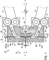
- Figures 1 and 2 show an extruder head 1 for extruding cord reinforced extrudate 90, in particular cord reinforced tire components for tire building, according to an exemplary embodiment of the invention.
- the extruder head 1 comprises a first head member H1 that holds or forms a die 2, a second head member H2 that forms or holds a cord guide 3 with respect to the die 2.
- the first head member H1 forms the die 2
- the second head member H2 comprises a casing 4 for holding the cord guide 3 with respect to the die 2.
- the die 2 is arranged for receiving a plurality of cords 8 and extrusion material 9 in a cord direction X.
- the extrusion material 9 is an elastomeric material, e.g. rubber.
- the cords 8 are made of a metal or a synthetic fiber.
- the cord guide 3 is arranged for guiding the plurality of cords 8 in a side-by-side relationship in a cord plane P into the die 2.
- the first head member H1 and the second head member H2 are mated or placed in mutual abutment at a mating plane M that extends transverse or perpendicular to the cord direction X and the cord plane P.
- the cord guide 3 and the casing 4 are located at a first side A of the mating plane M while the die 2 is located at a second side B of the mating plane M opposite to the first side A.
- the extruder head 1 further comprises a first flow channel 11 and a second flow channel 12 extending through the second head member H2 at the first side A of the mating plane M and at least partly in the second head member H2 at the second side B of the mating plane M.
- the first flow channel 11 and the second flow channel 12 are arranged to be placed in fluid communication with a first extruder 71 and a second extruder 72, respectively.
- a first gear pump 73 is provided between the first extruder 71 and the first flow channel 11 and a second gear pump 74 is provided between the second extruder 72 and the second flow channel 12 to provide a pressurized and/or uniform flow of extrusion material into the respective flow channels 11, 12.
- the die 2 comprises a first die member 21 that is arranged on a first side C of the cord plane P and a second die member 22 that is arranged on a second side D of the cord plane P, opposite to the first die member 21 at the first side C.
- the first die member 21 and the second die member 22 form a die opening 23 for shaping the extrusion material 9 in the desired shape of the extrudate 90.
- the die opening 23 has a height in a height direction H that defines the thickness T of the extrudate 90.
- the first die member 21 and the second die member 22 are inseparable, integral, monolithic or form a single piece.
- the die 2 is made from a rigid material such as metal.
- the first die member 21 and the second die member 22 are substantially tolerance free in the height direction H of the die opening 23.
- the first flow channel 11 extends through the first casing member 41 of the second head member H2 and debouches into the die opening 23 from the first side C of the cord plane P.
- the second flow channel 12 extends through the second casing member 42 of the second head member H2 and debouches into the die opening 23 from the second side D of the cord plane P.
- the first flow channel 11 is formed by a first circumferential wall 13 that defines or extends along a first flow path F1 for the extrusion material 9 through the second head member H2 and into the die opening 23.
- the second flow channel 12 is formed by a second circumferential wall 14 that defines a second flow path F2 for the extrusion material 9 through the second head member H2 and into the die opening 23.
- Both circumferential walls 13, 14 extend coaxially to the respective flow paths F1, F2. In other words, the flow paths F1, F2 extend through the heart and/or the center of the circumferential walls 13, 14.
- the first flow channel 11 and the second flow channel 12 each comprises a supply section S1, S3 for receiving the extrusion material 9 from the respective extruders 71, 72 and a so-called coat-hanger' section S2, S4 downstream of the respective supply sections S1, S3 for distributing the extrusion material 9 from the supply sections S1, S3 towards the die opening 23.
- the supply sections S1, S3 are circular or substantially circular in cross section.
- the cross sections of the supply sections S1, S3 are relatively constant through the extruder head 1.
- the coat-hanger sections S2, S4 diverge or widen in a lateral direction L parallel to the cord plane P and perpendicular to the cord direction X from or with respect to the relatively constant, cross section of the supply sections S1, S3 into a relatively flat and wide cross section that substantially corresponds to or merges into the die opening 23.
- the flow channel 11, 12 is provided with edges, flow dividers or other features (not shown) for optimizing the flow and/or the distribution of the extrusion material 9 in the coat-hanger sections S2, S4.
- the widening cross section of the coat-hanger sections S2, S4 gives these sections their characteristic shape, resembling the shape of a coat-hanger.
- the supply section S1 of the first flow channel 11 extends at an oblique angle with respect to the cord plane P through the first casing member 41 at the first side A of the mating plane M from the first extruder 71 and/or the first gear pump 73 towards the first die member 21.
- the supply section S1 intersects with the mating plane M from the first side A to the second side B at a first intersection W1.
- the supply section S1 deflects steeply towards the cord plane P.
- the coat-hanger section S2 of the first flow channel 11 starts at the widening of the first circumferential wall 13 in the lateral direction L, as shown in figure 2 and continues downstream of the supply section S1 until the debouching of the first flow channel 11 into the die opening 23.
- the first flow path F1 extends within a first range of eighty-five to ninety-five degrees with respect to the cord plane P along at least seventy percent, preferably at least eighty percent and most preferably at least ninety percent of the coat-hanger section S2.
- the first range is eighty-eight to ninety-two degrees. More in particular, at least seventy percent, preferably at least eighty percent and most preferably at least ninety percent of the surface area of the first circumferential wall 13 at said coat-hanger section S2 extends within the first range with respect to the cord plane P.
- first flow channel 11 and/or the first flow path F1 extends parallel or substantially parallel, e.g. within a deviation of five degrees or less, to the mating plane M.
- the second flow channel 12 is mirror-symmetrical to the first flow channel 11 with respect to the cord plane P.
- the second flow channel 12 comprises a corresponding supply section S3 that extends at an oblique angle with respect to the cord plane P through the second casing member 42 of the second head member H2 at the first side A of the mating plane M from the second extruder 72 and/or the second gear pump 74 towards the die 2.
- the second flow channel 12 intersects with the mating plane M from the first side A to the second side B at a second intersection W2.
- the supply section S3 of the second flow channel 12 deflects steeply towards the cord plane P.
- the second flow channel 12 further comprises a coat-hanger section S4 that starts at the widening of the second circumferential wall 14 in the lateral direction L, as shown in figure 2 , and continues downstream of the supply section S3 until the debouching of the second flow channel 12 into the die opening 23.
- the supply section S3 and the coat-hanger section S4 of the second flow channel 12 extend mirror-symmetrically at the second side D of the cord plane P to the supply section S1 and the coat-hanger section S2, respectively, of the first flow channel 11 at the first side C of the cord plane P and thus meet the same first range, surface area and other conditions as previously discussed for the supply section S1 and the coat-hanger section S2.
- a considerable part of the coat-hanger section S4 of the second flow channel 12 also extends parallel or substantially parallel, e.g. within a deviation of five degrees or less, to the mating plane M.
- the extruder head 1 comprises a plurality of interchangeable inserts 15-18 that form the circumferential walls 13, 14 of the respective flow channels 11, 12, at least at or along the coat-hanger sections S2, S4. Said inserts 15-18 are held in place by the head members H1, H2. The inserts 15-18 are replaceable by other inserts depending on the required shape of the flow channels 11, 12.
- Figures 1 and 3 show that the first flow channel 11 is formed by an first insert formed as a first coat-hanger half 15 on the first side A of the mating plane M and a second insert formed as a second coat-hanger half 16 on the second side B of the mating plane M.
- the second circumferential wall 14 at the coat-hanger section S4 of the second flow channel 12 is formed by a third insert in the form of a first coat-hanger half 17 on the first side A of the mating plane M and a fourth insert in the form of a second coat-hanger half 18 on the second side B of the mating plane M.
- the head members H1, H2 are securely clamped together with clamping members 24 about the mating plane M in the outer area around the escape channel 6 with the coat-hanger halves 15-18 mated about the same mating plane M in between.
- the first head member H1 and the second head member H2 are mated about the mating plane M.
- the cord guide 3 and/or the coat-hanger halves 15-18 the first head member H1 and the second head member H2 can be moved apart in a separation direction Z perpendicular to the mating plane M.
- the extruder head 1 is further provided with an escape channel 6 extending at or in the mating plane M in between the first head member H1 and the second head member H2.
- the escape channel 6 is preferably formed in the die 2, the casing 4 or both.
- the escape channel 6 extends around the die opening 23, the first flow channel 11 and the second flow channel 12 in the mating plane M and is fluidically separated from said die opening 23 and said flow channels 11, 12 by the mutual abutment of the first head member H1 and the second head member H2 at the mating plane M.
- the escape channel 6 comprises a ring-like main channel 61 extending circumferentially around a group of features including the first flow channel 11, the second flow channel 12 and the die opening 23, and a plurality of discharge channels 62 branching off from the main channel 61 to the outside of the extruder head 1.
- the head members H1, H2 are provided with a negative tolerance, i.e. a gap 45, to ensure that the coat-hanger halves 15-18 are clamped together securely.
- the gap 45 extends from the coat-hanger halves 15-18 to the escape channel 6.
- first flow channel 11 and/or the second flow channel 12 rises towards dangerous levels, e.g. a level that would cause the extruder head 1 to explode, the coat-hanger halves 15-18 are allowed to move apart slightly in the separation direction Z, while the parts of the head members H1, H2 outside of the escape channel 6 are still in mutual abutment about the mating plane M.
- the spacing allows the high pressure extrusion material 9 to escape into the escape channel 6 and out of the extruder head 1. This should relieve the pressure in the extrusion material 9 to acceptable levels.
- the cord guide 3 comprises a first guide member 31 on the first side C of the cord plane P, a second guide member 32 substantially on the second side B of the cord plane P and a holder 38 for holding the first guide member 31 and the second guide member 32 together on said opposite sides C, D of the cord plane P.
- One of the first guide member 31 and the second guide member 32 or both form a plurality of mutually parallel guide channels 33 extending side-by-side in the cord plane P, parallel or substantially parallel to the cord direction X.
- Each guide channel 33 is arranged for individually receiving a cord 8.
- the guide channels 33 are formed in or are at least partly located in the second guide member 32.
- the guide channels 33 are closed by abutment of the second guide member 32 with the first guide member 31.
- the cord guide 3 is provided with a leading end 30 facing towards the die 2 in the cord direction X.
- the first guide member 31 comprises a first deflecting surface 34 extending at the first side C of the cord plane P for deflecting the flow of extrusion material from the coat-hanger sections S2 of the first flow channel 11 towards and/or into the die opening 23.
- the second guide member 32 comprises a second deflecting surface 35 extending at the second side D of the cord plane P for deflecting the flow of extrusion material from the coat-hanger sections S4 of the second flow channel 12 towards and/or into the die opening 23.
- the second guide member 32 comprises a plurality of guide blocks 36 which are arranged side-by-side in a lateral direction L in the holder 38, parallel to the cord plane P and perpendicular to the cord direction X.
- Each guide block 36 comprises a number of the guide channels 33.
- each guide block 36 is provided with a half guide channel 33 that forms a complete guide channel 33 with a half guide channel 33 of a directly adjacent guide block 36.
- the guide channels 33 are easily damaged because of the thin walls between them.
- the extruder head 1 comes with a set of replacement blocks 37 to replace one or more guide blocks 36 when damaged or to change the configuration of the guide channels 33.
- the guide blocks 36 can be interchanged easily for one or more of the replacement blocks 37.
- the replacement blocks 37 may comprise alternatively shaped guide channels. When the die width is reduced, the replacement blocks 37 at the opposite ends of the plurality of guide blocks 36 may have less guide channels 33.
- the casing 4 comprises a first casing member 41 on the first side C of the cord plane P and a second casing member 42 on the second side D of the cord plane P.
- the first casing member 41 and the second casing member 42 form a receiving space 43 for receiving the cord guide 3.
- the casing 4 is arranged for holding and positioning the cord guide 3 with respect to the cord plane P and the die 2.
- the first casing member 41 and the second casing member 42 are inseparable, integral, monolithic or form a single piece.
- the casing 4 is made from a rigid material such as metal.
- the first casing member 41 and the second casing member 42 are substantially tolerance free in the height direction H of the receiving space 43.
- the cord guide 3 is slidably insertable into the receiving space 43 of the casing 4 in the cord direction X, parallel to the cord plane P, into an operative position as shown in figure 1 .
- the cord guide 3 is slidably removable from the casing 4 in a sliding direction Y opposite to the cord direction X into an inoperative position as shown in figure 6 .
- the cord guide 3 is preferably supported on a carriage (not shown) to keep the cord guide 3 level with the cord plane P. Hence, the cord guide 3 can be slid in the sliding direction Y over the plurality of cords 8, without removing said cords 8 from the cord guide 3.
- the cord guide 3 can be spaced apart from the extruder head 1 and the extruders 71, 72 in the inoperative position to allow the first guide member 31 to be lifted from the second guide member 32 and out of the holding member 38. Subsequently, new cords 8 can be inserted into the guide channels 33 of the cord guide 3.
- the extruder head 1 is provided with a locking member 5.
- the locking member 5 is received in a slot 44 in the casing 4 and is slidable with respect to said casing 4 in the lateral direction L between a locking position, as shown in figure 4A and a release position as shown in figure 4B .
- the locking member 5 comprises a locking plate 50 with a main opening 51 and a plurality of recesses 52.
- the recesses 52 are misaligned with the protrusions 53 of the cord guide 3 in the sliding direction Y.
- the cord guide 3 is retained with respect to the casing 4 in the sliding direction Y.
- the recesses 52 are aligned with the protrusions 53 of the cord guide 3 such that the cord guide 3 is removable from the casing 4 in the sliding direction Y.
- the individual aspects of the cord guide 3, in particular of the interchangeable guide blocks 36, the slidability in the sliding direction Y and/or the locking member 5, are independent from the aspects described hereafter in relation to the flow channels 11, 12 and can be made subject of divisional patent applications.
- the first deflecting surface 34 and the second deflecting surface 35 at the leading end 30 of the cord guide 3 are tangent or substantially tangent to the circumferential walls 13, 14 of the first flow channel 11 and the second flow channel 12, respectively, at the respective coat-hanger sections S2, S4 to smoothly receiving the flow of extrusion material 9 from the respective flow paths F1, F2.
- the deflecting surfaces 34, 35 are concave in the cord direction X.
- the deflecting surfaces 34, 35 are tangent to the cord plane P on the opposite sides C, D of said cord plane P.
- the deflecting surfaces 34, 35 are thus arranged for smoothly receiving and deflecting the flow of extrusion material 9 from the respective flow paths F1, F2 into the cord direction X.
- the deflecting surfaces 34, 35 can be substantially planar (not shown) and arranged at an angle in a second range of thirty to fifty degrees, and preferably approximately forty-five degrees, with respect to the cord plane P.
- the first flow channel 11 and the second flow channel 12 debouch onto the first deflecting surface 34 and the second deflecting surface 35, respectively, in a direction perpendicular or substantially perpendicular to the cord plane P and/or in a direction parallel or substantially parallel to the mating plane M.
- the extrusion material 9 will exert a pressure force onto the cord guide 3, with at least a component of said pressure force acting in the sliding direction Y opposite to the cord direction X.
- the cord guide 3 is locked by the locking member 5 in the operational position as shown in figure 1 .
- any tolerances between the cord guide 3 and the casing 4 in said sliding direction Y do not negatively influence the accuracy of the extruder head 1 in the height direction H.
- figure 7 shows an alternative extruder head 101 which differs from the previously discussed extruder head 1 in that its flow channels 111, 112 are formed by the head members H1, H2 rather than the inserts 15-18 of figure 1 .
- the first flow channel 111 is formed by the first die member 121 of the die 102 and the first casing member 141 of the casing 104 and the second flow channel 112 is formed by the second die member 122 of the die 102 and the second casing member 142 of the casing 104.
- the flow channels 111, 112 are still divided into a supply sections S1, S3 with a relatively constant, circular cross section and widening coat-hanger sections S2, S4, similar to the sections S1-S4 in figures 1 , 2 and 3 .
- the coat-hanger sections S2, S4 still meet the previously discussed first range.
- the head members H1, H2 are separable when the pressure exceeds a threshold value, to relieve the pressure in the extrusion material 9.
- the invention relates to an extruder head 1, 101 for extruding cord reinforced extrudate, wherein the extruder head 1, 101 comprises a die 2, 102 and a cord guide 3, wherein the extruder head 1, 101 further comprises a first flow channel 11, 111 that extends along a first flow path F1 through the extruder head 1, 101 at and debouches into the die 2, 102 from a first side C of a cord plane P and a second flow channel 12, 112 that extends along a second flow path F2 through the extruder head 1, 101 at and debouches into the die 2, 102 from a second side D of the cord plane P, wherein the first flow path F1 and the second flow path F2 each comprise a supply section S1, S3 and a coat-hanger section S2, S4, wherein the first flow path F1, and the second flow path F2, in their respective coat-hanger sections S2, S4, extend within a first range of eighty-five to ninety-five degrees with respect to the cord plane P along at least seventy
Landscapes
- Engineering & Computer Science (AREA)
- Mechanical Engineering (AREA)
- Manufacturing & Machinery (AREA)
- Textile Engineering (AREA)
- Extrusion Moulding Of Plastics Or The Like (AREA)
- Special Chairs (AREA)
Claims (21)
- Extruderkopf (1) zum Extrudieren kord-verstärkten Extrudats (90),
wobei der Extruderkopf eine Düse (2) umfasst zum Aufnehmen von Kordfäden (8) und Extrusionsmaterial (9) in einer Kordrichtung (X),sowie eine Kordführung (3) zum Führen der Kordfäden Seite an Seite in einer Kordebene (P), parallel zu der Kordrichtung, in die Düse,
wobei der Extruderkopf ferner einen ersten Strömungskanal (11) umfasst, der entlang eines ersten Strömungswegs (F1) durch den Extruderkopf bei der und in die Düse mündend, von einer ersten Seite der Kordebene verläuft, sowie einen zweiten Strömungskanal (12), der entlang eines zweiten Strömungswegs (F2) duch den Extruderkopf bei der und in die Düse mündend, von einer zweiten Seite der Kordebene, gegenüber der ersten Seite, verläuft, wobei der erste Strömungsweg und der zweite Strömungsweg jeweils einen Versorgungsabschnitt (S1, S3) und einen Kleiderbügelabschnitt (S2, S4) mit einem sich aufweitenden Querschnittsbereich stromabwärts des Versorgungsabschnitts umfassen, wobei der erste Strömungsweg und der zweite Strömungsweg in ihren jeweiligen Kleiderbügelabschnitten unter einem Winkel innerhalb eines ersten Bereichs von fünfundachtzig bis fünfundneunzig Grad, vorzugsweise achtundachtzig bis zweiundneunzig Grad, in Bezug auf die Kordebene entlang wenigstens siebzig Prozent der jeweiligen Kleiderbügelabschnitte, verlaufen. - Extruderkopf nach Anspruch 1, wobei der erste Strömungsweg und der zweite Strömungsweg in ihren jeweiligen Kleiderbügelabschnitten und bis zu der Kordebene unter einem Winkel innerhalb des ersten Bereichs in Bezug auf die Kordebene entlang wenigstens siebzig Prozent der jeweiligen Kleiderbügelabschnitte verlaufen.
- Extruderkopf nach einem der vorstehenden Ansprüche, wobei die jeweiligen Strömungswege senkrecht zu der Kordebene in den jeweiligen Kleiderbügelabschnitten verlaufen.
- Extruderkopf nach einem der vorstehenden Ansprüche, wobei die jeweiligen Strömungswege innerhalb des ersten Bereichs in Bezug auf die Kordebene entlang wenigstens achtzig Prozent der jeweiligen Kleiderbügelabschnitte, bevorzugter entlang wenigstens neunzig Prozent der jeweiligen Kleiderbügelabschnitte und am Bevorzugtesten in den gesamten jeweiligen Kleiderbügelabschnitten, verlaufen.
- Extruderkopf nach einem der vorstehenden Ansprüche, wobei die Kleiderbügelabschnitte in die Düse in einer Richtung senkrecht oder im Wesentlichen senkrecht zu der Kordebene münden.
- Extruderkopf nach einem der vorstehenden Ansprüche, wobei die Kordführung ein vorderes Ende (30) umfasst, das sich wenigstens zum Teil in die Düse erstreckt, wobei das vordere Ende mit einer ersten Ablenkfläche (34) und einer zweiten Ablenkfläche (35) versehen ist, die sich an gegenüberliegenden Seiten der Kordebene erstrecken und in Kordrichtung zu der Düse weisen, wobei die Kleiderbügelabschnitte des ersten Strömungskanals und des zweiten Strömungskanals auf die erste Ablenkfläche bzw. die zweite Ablenkfläche in einer Richtung senkrecht oder im Wesentlichen senkrecht zu der Kordebene münden, wobei die erste Ablenkfläche und die zweite Ablenkfläche derart angeordnet sind, dass sie das Extrusionsmaterial von dem ersten Strömungskanal bzw. dem zweiten Strömungskanal in Richtung und/oder in die Düse ablenken, wobei bevorzugt die erste Ablenkfläche und die zweite Ablenkfläche tangential oder im Wesentlichen tangential zu den jeweiligen Kleiderbügelabschnitten und der Kordebene sind.
- Extruderkopf nach einem der vorstehenden Ansprüche, wobei die Kleiderbügelabschnitte des ersten Strömungskanals und des zweiten Strömungskanals jeweils eine umlaufende Wand (13, 14) umfassen, wobei der Extruderkopf für jeden Strömungskanal eine erste Kleiderbügelhälfte (15, 17) und eine zweite Kleiderbügelhälfte (16, 18) umfasst, die sich wechselseitig berührend an gegenüberliegenden Seiten (A, B) einer Paarebene (M) platziert angeordnet sind, um die umlaufende Wand des jeweiligen Strömungskanals auszubilden, wobei vorzugsweise die Paarebene transversal oder senkrecht zu der Kordebene und der Kordrichtung verläuft.
- Extruderkopf nach Anspruch 7, wobei die jeweiligen Strömungswege parallel oder im Wesentlichen parallel zu der Paarebene entlang wenigstens siebzig Prozent der jeweiligen Kleiderbügelabschnitte verlaufen.
- Extruderkopf nach einem der vorstehenden Ansprüche, wobei der erste Strömungsweg und der zweite Strömungsweg die Paarebene schneiden und/oder zumindest teilweise in der Paarebene bei den jeweiligen Kleiderbügelabschnitten verlaufen.
- Extruderkopf nach einem der Ansprüche 7 - 9, wobei die umfängliche Wand jedes Strömungskanals symmetrisch oder im Wesentlichen symmetrisch um die Paarebene entlang wenigstens siebzig Prozent der jeweiligen Kleiderbügelabschnitte ist.
- Extruderkopf nach einem der Ansprüche 7 - 10, wobei wenigstens siebzig Prozent des Oberflächenbereichs der umlaufenden Wand bei den jeweiligen Kleiderbügelabschnitten innerhalb des ersten Bereichs in Bezug auf die Kordebene verläuft, wobei bevorzugt wenigstens achtzig Prozent und bevorzugt wenigstens neunzig Prozent des Oberflächenbereichs der umlaufenden Wand bei den jeweiligen Kleiderbügelabschnitten innerhalb des ersten Bereichs in Bezug auf die Kordebene verläuft.
- Extruderkopf nach einem der Ansprüche 7 - 11, wobei die erste Kleiderbügelhälfte und die zweite Kleiderbügelhälfte in einer Trennrichtung parallel zu der Kordrichtung trennbar sind.
- Extruderkopf nach einem der Ansprüche 7 - 12, wobei der Extruderkopf ein erstes Kopfteil (H1) zum Halten oder Ausbilden der Düse und ein zweites Kopfteil (H2) zum Halten oder Ausbilden der Kordführung umfasst, wobei die ersten Kleiderbügelhälften durch das erste Kopfteil gebildet werden und wobei die zweiten Kleiderbügelhälften durch das zweite Kopfteil gebildet werden, wobei der Extruderkopf bevorzugt einen Sicherheitskanal (6) umfasst, der sich bei der Paarebene erstreckt, wobei der Sicherheitskanal von dem ersten Strömungskanal und dem zweiten Strömungskanal getrennt ist, wenn das erste Kopfteil und das zweite Kopfteil einander bei der Paarebene berühren und wobei der Sicherheitskanal fluidmäßig mit dem ersten Strömungskanal und/oder dem zweiten Strömungskanal in Kommunikation steht, wenn das erste Kopfteil und das zweite Kopfteil in der Trennrichtung getrennt sind.
- Extruderkopf nach einem der Ansprüche 7 - 13, wobei der Extruderkopf ein erstes Kopfteil zum Halten oder Ausbilden der Düse und ein zweites Kopfteil zum Halten oder Ausbilden der Kordführung umfasst, wobei die ersten Kleiderbügelhälften Einsätze sind, die von dem ersten Kopfteil gehalten werden und wobei die zweiten Kleiderbügelhälften Einsätze sind, die von dem zweiten Kopfteil gehalten werden, wobei vorzugsweise das erste Kopfteil und das zweite Kopfteil in einer Trennrichtung parallel zu der Kordebene trennbar sind und/oder wobei das erste Kopfteil und das zweite Kopfteil derart angeordnet sind, dass sie, einander gegenseitig berührend, an gegenüberliegenden Seiten der Paarebene platziert sind.
- Extruderkopf nach Anspruch 14, wobei der Extruderkopf einen bei der Paarebene verlaufenden Sicherheitskanal umfasst, wobei der Sicherheitskanal von dem ersten Strömungskanal und dem zweiten Strömungskanal durch die Einsätze getrennt ist, wenn Einsätze in Berührung stehen bei der Paarebene und wobei der Sicherheitskanal fluidmäßig mit dem ersten Strömungskanal und/oder dem zweiten Strömungskanal in Kommunikation steht, wenn die Einsätze in der Trennrichtung getrennt sind, wobei die Kopfteile vorzugsweise derart angeordnet sind, dass sie in gegenseitiger Berührung außerhalb des Sicherheitskanals verbleiben, während die Einsätze in der Trennrichtung getrennt werden.
- Extruderkopf nach einem der Ansprüche 13 - 15, wobei das zweite Kopfteil ein erstes Gehäuseelement (41) an der ersten Seite der Kordebene und ein zweites Gehäuseelement (42) an der zweiten Seite der Kordebene umfasst, wobei das erste Gehäuseelement und das zweite Gehäuseelement zusammen einen Aufnahmeraum (43) ausbilden zum Aufnehmen der Kordführung, wobei das erste Gehäuseelement und das zweite Gehäuseelement in einer Normalrichtung senkrecht zu der Kordebene untrennbar sind, wobei vorzugsweise das erste Gehäuseelement und das zweite Gehäuseelement ein Stück bilden.
- Extruderkopf nach einem der vorstehenden Ansprüche, wobei die Düse ein erstes Düsenelement an der ersten Seite der Kordebene und ein zweites Düsenelement an der zweiten Seite der Kordebene umfasst, wobei das erste Düsenelement und das zweite Düsenelement zusammen eine Düsenöffnung (43) ausbilden, durch die das Extrudat den Extruderkopf verlässt, wobei das erste Düsenelement und das zweite Düsenelement in einer Normalrichtung senkrecht zu der Kordebene untrennbar sind, wobei bevorzugt das erste Düsenelement und das zweite Düsenelement ein Stück bilden.
- Extruderkopf nach einem der vorstehenden Ansprüche, wobei die Kordführung in eine und aus einer Betriebsstellung in dem Extruderkopf in der Kordrichtung bzw. einer Verschieberichtung (Y), entgegengesetzt zu der Kordrichtung, verschiebbar ist, wobei vorzugsweise der Extruderkopf ferner ein Verriegelungselement (5) umfasst, das derart angeordnet ist, dass es die Kordführung gegenüber einer Verschiebung in der Verschieberichtung verriegelt, wenn sich die Kordführung in der Betriebsstellung befindet.
- Extruderkopf nach einem der vorstehenden Ansprüche, wobei die Kordführung ein erstes Führungselement an der ersten Seite der Kordebene und ein zweites Führungselement an der zweiten Seite der Kordebene umfasst, wobei das erste Führungselement oder das zweite Führungselement mehrere austauschbare Führungsblöcke (36) umfasst, die Seite an Seite in einer lateralen Richtung parallel zu der Kordebene und senkrecht zu der Kordrichtung angeordnet sind, wobei jeder Block mehrere Führungskanäle (33) umfasst, die in der Kordrichtung bei und parallel zu der Kordebene zur Aufnahme der Kordfäden verlaufen, wobei der Extruderkopf vorzugsweise ferner einen Satz Ersatzblöcke (37) umfasst, um einen oder mehrere der Führungsblöcke der Kordführung zu ersetzen, wobei wenigstens einer der Ersatzblöcke die gleiche Vielzahl an Führungskanälen umfasst wie Führungsblöcke der Kordführung; oder, wobei der Extruderkopf ferner einen Satz Ersatzblöcke umfasst zum Ersetzen eines oder mehrerer der Führungsblöcke der Kordführung, wobei wenigstens einer der Ersatzblöcke eine unterschiedliche Anzahl oder Form von Führungskanälen als die Führungsblöcke der Kordführung umfasst.
- Extruderkopf nach Anspruch 19, wobei die Vielzahl an Führungskanälen wenigstens einen Führungskanal umfasst, der durch zwei unmittelbar angrenzende Führungsblöcke definiert ist.
- Verfahren zum Extrudieren kordverstärkten Extrudats unter Verwendung des Führungskopfs nach einem der vorstehenden Ansprüche, wobei das Verfahren die Schritte umfasst des Zuführens unter Druck stehenden Extrusionsmaterials in den ersten Strömungskanal und den zweiten Strömungskanal und des Absorbierens der Druckkräfte, die von dem unter Druck stehenden Extrusionsmaterial erzeugt wurden in den jeweiligen Kleiderbügelabschnitten in einer Richtung parallel oder im Wesentlichen parallel zu der Kordebene.
Priority Applications (2)
| Application Number | Priority Date | Filing Date | Title |
|---|---|---|---|
| RS20200869A RS60601B1 (sr) | 2016-05-25 | 2017-05-12 | Glava ektsrudera za istiskivanje žicom ojačanog materijala |
| PL17728672T PL3463798T3 (pl) | 2016-05-25 | 2017-05-12 | Głowica wytłaczarki do wytłaczania wzmocnionej kordem wytłoczyny |
Applications Claiming Priority (2)
| Application Number | Priority Date | Filing Date | Title |
|---|---|---|---|
| NL2016826A NL2016826B1 (en) | 2016-05-25 | 2016-05-25 | Extruder head for extruding cord-reinforced extrudate |
| PCT/NL2017/050294 WO2017204624A1 (en) | 2016-05-25 | 2017-05-12 | Extruder head for extruding cord-reinforced extrudate |
Publications (2)
| Publication Number | Publication Date |
|---|---|
| EP3463798A1 EP3463798A1 (de) | 2019-04-10 |
| EP3463798B1 true EP3463798B1 (de) | 2020-05-27 |
Family
ID=56292856
Family Applications (1)
| Application Number | Title | Priority Date | Filing Date |
|---|---|---|---|
| EP17728672.1A Active EP3463798B1 (de) | 2016-05-25 | 2017-05-12 | Extruderkopf zum strangpressen eines kordverstärkten extrudats |
Country Status (15)
| Country | Link |
|---|---|
| US (1) | US10906261B2 (de) |
| EP (1) | EP3463798B1 (de) |
| JP (1) | JP6807955B2 (de) |
| KR (1) | KR102080848B1 (de) |
| CN (3) | CN113619068B (de) |
| BR (1) | BR112018073901B1 (de) |
| ES (1) | ES2797908T3 (de) |
| HU (1) | HUE050077T2 (de) |
| MX (1) | MX2018013950A (de) |
| MY (1) | MY190776A (de) |
| NL (1) | NL2016826B1 (de) |
| PL (1) | PL3463798T3 (de) |
| RS (1) | RS60601B1 (de) |
| RU (1) | RU2728999C2 (de) |
| WO (1) | WO2017204624A1 (de) |
Families Citing this family (4)
| Publication number | Priority date | Publication date | Assignee | Title |
|---|---|---|---|---|
| US11685095B2 (en) * | 2015-06-30 | 2023-06-27 | The Goodyear Tire & Rubber Company | Method and apparatus for forming tire components using a coextruded strip |
| CN110370596B (zh) * | 2019-07-24 | 2021-09-17 | 重庆海塑建材有限公司 | 自旋混料式门窗框塑钢型材挤塑机进料斗 |
| JP7213275B2 (ja) * | 2021-01-08 | 2023-01-26 | 日本碍子株式会社 | 押出成形用ダイ及び押出成形機 |
| IT202100032852A1 (it) * | 2021-12-29 | 2023-06-29 | Semplice S P A | Testa di estrusione perfezionata, in particolare per l’estrusione di un materiale polimerico per formare il rivestimento di un filo o cavo o simili. |
Family Cites Families (32)
| Publication number | Priority date | Publication date | Assignee | Title |
|---|---|---|---|---|
| US4150929A (en) * | 1977-06-22 | 1979-04-24 | B & H Tool Company, Inc. | Ribbon cable extrusion apparatus |
| JPS5436374A (en) * | 1977-08-26 | 1979-03-17 | Sumitomo Rubber Ind | Code topping apparatus |
| JPS5636422U (de) * | 1979-08-30 | 1981-04-08 | ||
| JPS5636422A (en) | 1979-09-03 | 1981-04-09 | Mitsui Toatsu Chem Inc | Preparation of methyl tertiary-butyl ether |
| IT1123875B (it) * | 1979-10-17 | 1986-04-30 | Pirelli | Testa di estrusione piana |
| US4657718A (en) * | 1985-02-22 | 1987-04-14 | The Firestone Tire & Rubber Company | Coextrusion method |
| IT1219242B (it) * | 1988-04-27 | 1990-05-03 | Firestone Int Dev Spa | Testa di estrusione per materiale in foglio internamente armato con elementi in filo di rinforzo distribuiti con passo relativamente ridotto |
| AU8275691A (en) * | 1990-08-29 | 1992-03-05 | Chicopee | Restrictor bar and sealing arrangement for a melt blown die apparatus |
| IT1245462B (it) * | 1991-03-15 | 1994-09-20 | Firestone Int Dev Spa | Testa di estrusione per la realizzazione di fasce armate per pneumatici di veicoli stradali |
| US5292472A (en) * | 1992-12-18 | 1994-03-08 | Bridgestone Corporation | Coextrusion apparatus and method with rotating cord guidance |
| JPH07146428A (ja) * | 1993-11-24 | 1995-06-06 | Yazaki Corp | 帯状光ファイバテープ心線のコーティングヘッド |
| JPH08103972A (ja) * | 1994-08-10 | 1996-04-23 | Sumitomo Rubber Ind Ltd | コードのトッピング方法 |
| GB2326613A (en) * | 1997-06-23 | 1998-12-30 | Pirelli General Plc | Plastics extrusion |
| DE19803362A1 (de) * | 1998-01-29 | 1999-08-05 | Sartorius Gmbh | Geschäumte poröse Membranen aus thermoplastischen Polymeren sowie Verfahren und Vorrichtung zu ihrer Herstellung |
| RU2197383C2 (ru) * | 2000-09-04 | 2003-01-27 | Общество с ограниченной ответственностью "Специальное конструкторско-технологическое бюро "Маяк" | Экструзионная головка и устройство для смещения и фиксации дорна |
| JP4017454B2 (ja) * | 2002-06-25 | 2007-12-05 | 株式会社ブリヂストン | 押出機のゴム被覆ヘッド |
| RU2337825C2 (ru) * | 2003-06-30 | 2008-11-10 | Пирелли Пнеуматичи С.П.А. | Способ изготовления эластомерных компонентов шины для колес транспортных средств |
| JP2005193494A (ja) * | 2004-01-06 | 2005-07-21 | Toyo Tire & Rubber Co Ltd | 押出機用ダイインサート |
| JP4730881B2 (ja) * | 2004-10-14 | 2011-07-20 | 株式会社ブリヂストン | ゴム被覆ヘッド |
| JP2006255980A (ja) * | 2005-03-16 | 2006-09-28 | Yokohama Rubber Co Ltd:The | コード補強材料の製造方法と装置及びタイヤ構成材料 |
| US20070122605A1 (en) * | 2005-11-30 | 2007-05-31 | Downing Daniel R | Apparatus and method of manufacturing reduced gauge tire ply |
| US8162644B2 (en) | 2006-01-17 | 2012-04-24 | Toyo Tire & Rubber Co., Ltd. | Die for extrusion forming head |
| FR2904256B1 (fr) * | 2006-07-27 | 2008-11-21 | Michelin Soc Tech | Dispositif de gainage de cable a filiere mobile |
| NL1033470C2 (nl) | 2007-03-01 | 2008-09-02 | Vmi Epe Holland | Inrichting voor het maken van een gordellaag. |
| KR101571996B1 (ko) * | 2007-09-10 | 2015-11-25 | 이에이치씨 캐나다, 인크. | 열가소성 핸드레일의 압출을 위한 방법 및 장치 |
| US9981415B2 (en) * | 2007-09-10 | 2018-05-29 | Ehc Canada, Inc. | Method and apparatus for extrusion of thermoplastic handrail |
| JP4853492B2 (ja) * | 2008-04-30 | 2012-01-11 | 日立電線株式会社 | 押し出し方法及び押し出し装置 |
| JP5374136B2 (ja) * | 2008-12-17 | 2013-12-25 | 住友ゴム工業株式会社 | プライ材料製造方法、およびプライ材料を用いた空気入りタイヤ |
| NL2012075C2 (en) * | 2014-01-10 | 2015-07-13 | Vmi Holland Bv | Extruder tooling. |
| US20160059466A1 (en) * | 2014-08-28 | 2016-03-03 | The Goodyear Tire And Rubber Company | Apparatus for producing laminated fabric ply strips |
| US9770859B2 (en) * | 2014-12-18 | 2017-09-26 | The Goodyear Tire & Rubber Company | Apparatus for producing laminated fabric ply strips |
| NL2014454B1 (en) | 2015-03-13 | 2016-10-14 | Vmi Holland Bv | Extruder and method for extruding cord reinforced tire components. |
-
2016
- 2016-05-25 NL NL2016826A patent/NL2016826B1/en not_active IP Right Cessation
-
2017
- 2017-05-12 KR KR1020177031616A patent/KR102080848B1/ko active Active
- 2017-05-12 JP JP2018560852A patent/JP6807955B2/ja active Active
- 2017-05-12 RU RU2018138758A patent/RU2728999C2/ru active
- 2017-05-12 HU HUE17728672A patent/HUE050077T2/hu unknown
- 2017-05-12 WO PCT/NL2017/050294 patent/WO2017204624A1/en not_active Ceased
- 2017-05-12 MX MX2018013950A patent/MX2018013950A/es unknown
- 2017-05-12 RS RS20200869A patent/RS60601B1/sr unknown
- 2017-05-12 CN CN202110888848.2A patent/CN113619068B/zh active Active
- 2017-05-12 PL PL17728672T patent/PL3463798T3/pl unknown
- 2017-05-12 MY MYPI2018704191A patent/MY190776A/en unknown
- 2017-05-12 EP EP17728672.1A patent/EP3463798B1/de active Active
- 2017-05-12 CN CN201780031892.3A patent/CN109219507B/zh active Active
- 2017-05-12 US US16/304,024 patent/US10906261B2/en active Active
- 2017-05-12 BR BR112018073901-4A patent/BR112018073901B1/pt active IP Right Grant
- 2017-05-12 ES ES17728672T patent/ES2797908T3/es active Active
- 2017-05-12 CN CN202110881997.6A patent/CN113619067B/zh active Active
Non-Patent Citations (1)
| Title |
|---|
| None * |
Also Published As
| Publication number | Publication date |
|---|---|
| MY190776A (en) | 2022-05-12 |
| US20200282621A1 (en) | 2020-09-10 |
| CN113619068B (zh) | 2023-08-29 |
| KR102080848B1 (ko) | 2020-02-24 |
| BR112018073901A8 (pt) | 2022-08-09 |
| EP3463798A1 (de) | 2019-04-10 |
| NL2016826A (en) | 2017-11-30 |
| US10906261B2 (en) | 2021-02-02 |
| RU2018138758A3 (de) | 2020-05-27 |
| CN113619067A (zh) | 2021-11-09 |
| CN113619068A (zh) | 2021-11-09 |
| JP6807955B2 (ja) | 2021-01-06 |
| KR20170141213A (ko) | 2017-12-22 |
| BR112018073901A2 (pt) | 2019-02-26 |
| CN109219507A (zh) | 2019-01-15 |
| HUE050077T2 (hu) | 2020-11-30 |
| JP2019516588A (ja) | 2019-06-20 |
| RS60601B1 (sr) | 2020-08-31 |
| RU2018138758A (ru) | 2020-05-12 |
| PL3463798T3 (pl) | 2020-11-16 |
| CN109219507B (zh) | 2021-08-17 |
| CN113619067B (zh) | 2024-07-12 |
| BR112018073901B1 (pt) | 2022-11-29 |
| WO2017204624A1 (en) | 2017-11-30 |
| RU2728999C2 (ru) | 2020-08-03 |
| MX2018013950A (es) | 2019-04-01 |
| ES2797908T3 (es) | 2020-12-04 |
| NL2016826B1 (en) | 2017-12-12 |
Similar Documents
| Publication | Publication Date | Title |
|---|---|---|
| US10906261B2 (en) | Extruder head for extruding cord-reinforced extrudate | |
| IT9020036A1 (it) | Stampo e metodo per la vulcanizzazione di pneumatici e metodo per fabbricare stampi | |
| EP2995439B1 (de) | Vorrichtung und verfahren zur herstellung von streifen aus laminierten stofflagen | |
| EP3606722B1 (de) | Extrudersystem und verfahren zum extrudieren von kordverstärkten reifenkomponenten | |
| EP2960042B1 (de) | Verteiler mit variierendem übergangsbereich | |
| EP1352728B1 (de) | Vorrichtung und Verfahren zum Extrudieren von mehrlagigen Kunststoffen, wobei das Muster der Lagen durch einfachen Austausch des Strömungsblocks in der Düse variiert wird | |
| JP2019516588A5 (de) | ||
| US7717691B2 (en) | Tire mold with vent inlet disposed under mold rib | |
| EP3338996B1 (de) | Vorrichtung zur herstellung von streifen aus laminierten stofflagen | |
| EP2554349B1 (de) | Formentlüftungsvorrichtung | |
| US11420373B2 (en) | Preform device for positioning extruded rubber mixtures, and extruder mold system comprising the preform device for molding extruded rubber mixtures into a complete rubber element, and corresponding extruder system | |
| TWI692397B (zh) | 用以擠壓出簾布強化押出物的押出機頭與使用押出機頭以擠壓出簾布強化押出物的方法 | |
| KR20160003401U (ko) | 사출기용 노즐 어셈블리의 벤트링 | |
| NL2018638B1 (en) | Extruder system and method for extruding cord-reinforced tire components | |
| CZ7717U1 (cs) | Odvzdušňovací systém vulkanizační tvárnice | |
| ITFI990099A1 (it) | Regolatore di flusso per macchine per la produzione di pasta alimentare. |
Legal Events
| Date | Code | Title | Description |
|---|---|---|---|
| STAA | Information on the status of an ep patent application or granted ep patent |
Free format text: STATUS: UNKNOWN |
|
| STAA | Information on the status of an ep patent application or granted ep patent |
Free format text: STATUS: THE INTERNATIONAL PUBLICATION HAS BEEN MADE |
|
| PUAI | Public reference made under article 153(3) epc to a published international application that has entered the european phase |
Free format text: ORIGINAL CODE: 0009012 |
|
| STAA | Information on the status of an ep patent application or granted ep patent |
Free format text: STATUS: REQUEST FOR EXAMINATION WAS MADE |
|
| 17P | Request for examination filed |
Effective date: 20181029 |
|
| AK | Designated contracting states |
Kind code of ref document: A1 Designated state(s): AL AT BE BG CH CY CZ DE DK EE ES FI FR GB GR HR HU IE IS IT LI LT LU LV MC MK MT NL NO PL PT RO RS SE SI SK SM TR |
|
| AX | Request for extension of the european patent |
Extension state: BA ME |
|
| DAV | Request for validation of the european patent (deleted) | ||
| DAX | Request for extension of the european patent (deleted) | ||
| REG | Reference to a national code |
Ref country code: DE Ref legal event code: R079 Ref document number: 602017017333 Country of ref document: DE Free format text: PREVIOUS MAIN CLASS: B29C0047020000 Ipc: B29C0048156000 |
|
| GRAP | Despatch of communication of intention to grant a patent |
Free format text: ORIGINAL CODE: EPIDOSNIGR1 |
|
| STAA | Information on the status of an ep patent application or granted ep patent |
Free format text: STATUS: GRANT OF PATENT IS INTENDED |
|
| INTG | Intention to grant announced |
Effective date: 20191220 |
|
| RIC1 | Information provided on ipc code assigned before grant |
Ipc: B29D 30/38 20060101ALI20191206BHEP Ipc: B29C 48/49 20190101ALI20191206BHEP Ipc: B29C 48/156 20190101AFI20191206BHEP Ipc: B29C 48/25 20190101ALI20191206BHEP Ipc: B29C 48/07 20190101ALI20191206BHEP Ipc: B29C 48/305 20190101ALI20191206BHEP |
|
| GRAS | Grant fee paid |
Free format text: ORIGINAL CODE: EPIDOSNIGR3 |
|
| GRAA | (expected) grant |
Free format text: ORIGINAL CODE: 0009210 |
|
| STAA | Information on the status of an ep patent application or granted ep patent |
Free format text: STATUS: THE PATENT HAS BEEN GRANTED |
|
| AK | Designated contracting states |
Kind code of ref document: B1 Designated state(s): AL AT BE BG CH CY CZ DE DK EE ES FI FR GB GR HR HU IE IS IT LI LT LU LV MC MK MT NL NO PL PT RO RS SE SI SK SM TR |
|
| REG | Reference to a national code |
Ref country code: GB Ref legal event code: FG4D |
|
| REG | Reference to a national code |
Ref country code: CH Ref legal event code: EP |
|
| REG | Reference to a national code |
Ref country code: NL Ref legal event code: FP Ref country code: FI Ref legal event code: FGE |
|
| REG | Reference to a national code |
Ref country code: AT Ref legal event code: REF Ref document number: 1274118 Country of ref document: AT Kind code of ref document: T Effective date: 20200615 |
|
| REG | Reference to a national code |
Ref country code: DE Ref legal event code: R096 Ref document number: 602017017333 Country of ref document: DE |
|
| REG | Reference to a national code |
Ref country code: LT Ref legal event code: MG4D |
|
| PG25 | Lapsed in a contracting state [announced via postgrant information from national office to epo] |
Ref country code: GR Free format text: LAPSE BECAUSE OF FAILURE TO SUBMIT A TRANSLATION OF THE DESCRIPTION OR TO PAY THE FEE WITHIN THE PRESCRIBED TIME-LIMIT Effective date: 20200828 Ref country code: SE Free format text: LAPSE BECAUSE OF FAILURE TO SUBMIT A TRANSLATION OF THE DESCRIPTION OR TO PAY THE FEE WITHIN THE PRESCRIBED TIME-LIMIT Effective date: 20200527 Ref country code: IS Free format text: LAPSE BECAUSE OF FAILURE TO SUBMIT A TRANSLATION OF THE DESCRIPTION OR TO PAY THE FEE WITHIN THE PRESCRIBED TIME-LIMIT Effective date: 20200927 Ref country code: PT Free format text: LAPSE BECAUSE OF FAILURE TO SUBMIT A TRANSLATION OF THE DESCRIPTION OR TO PAY THE FEE WITHIN THE PRESCRIBED TIME-LIMIT Effective date: 20200928 Ref country code: LT Free format text: LAPSE BECAUSE OF FAILURE TO SUBMIT A TRANSLATION OF THE DESCRIPTION OR TO PAY THE FEE WITHIN THE PRESCRIBED TIME-LIMIT Effective date: 20200527 Ref country code: NO Free format text: LAPSE BECAUSE OF FAILURE TO SUBMIT A TRANSLATION OF THE DESCRIPTION OR TO PAY THE FEE WITHIN THE PRESCRIBED TIME-LIMIT Effective date: 20200827 |
|
| REG | Reference to a national code |
Ref country code: SK Ref legal event code: T3 Ref document number: E 35067 Country of ref document: SK |
|
| PG25 | Lapsed in a contracting state [announced via postgrant information from national office to epo] |
Ref country code: HR Free format text: LAPSE BECAUSE OF FAILURE TO SUBMIT A TRANSLATION OF THE DESCRIPTION OR TO PAY THE FEE WITHIN THE PRESCRIBED TIME-LIMIT Effective date: 20200527 Ref country code: LV Free format text: LAPSE BECAUSE OF FAILURE TO SUBMIT A TRANSLATION OF THE DESCRIPTION OR TO PAY THE FEE WITHIN THE PRESCRIBED TIME-LIMIT Effective date: 20200527 Ref country code: BG Free format text: LAPSE BECAUSE OF FAILURE TO SUBMIT A TRANSLATION OF THE DESCRIPTION OR TO PAY THE FEE WITHIN THE PRESCRIBED TIME-LIMIT Effective date: 20200827 |
|
| REG | Reference to a national code |
Ref country code: HU Ref legal event code: AG4A Ref document number: E050077 Country of ref document: HU |
|
| REG | Reference to a national code |
Ref country code: ES Ref legal event code: FG2A Ref document number: 2797908 Country of ref document: ES Kind code of ref document: T3 Effective date: 20201204 |
|
| REG | Reference to a national code |
Ref country code: AT Ref legal event code: MK05 Ref document number: 1274118 Country of ref document: AT Kind code of ref document: T Effective date: 20200527 |
|
| PG25 | Lapsed in a contracting state [announced via postgrant information from national office to epo] |
Ref country code: AL Free format text: LAPSE BECAUSE OF FAILURE TO SUBMIT A TRANSLATION OF THE DESCRIPTION OR TO PAY THE FEE WITHIN THE PRESCRIBED TIME-LIMIT Effective date: 20200527 |
|
| PG25 | Lapsed in a contracting state [announced via postgrant information from national office to epo] |
Ref country code: SM Free format text: LAPSE BECAUSE OF FAILURE TO SUBMIT A TRANSLATION OF THE DESCRIPTION OR TO PAY THE FEE WITHIN THE PRESCRIBED TIME-LIMIT Effective date: 20200527 Ref country code: AT Free format text: LAPSE BECAUSE OF FAILURE TO SUBMIT A TRANSLATION OF THE DESCRIPTION OR TO PAY THE FEE WITHIN THE PRESCRIBED TIME-LIMIT Effective date: 20200527 Ref country code: EE Free format text: LAPSE BECAUSE OF FAILURE TO SUBMIT A TRANSLATION OF THE DESCRIPTION OR TO PAY THE FEE WITHIN THE PRESCRIBED TIME-LIMIT Effective date: 20200527 Ref country code: DK Free format text: LAPSE BECAUSE OF FAILURE TO SUBMIT A TRANSLATION OF THE DESCRIPTION OR TO PAY THE FEE WITHIN THE PRESCRIBED TIME-LIMIT Effective date: 20200527 |
|
| REG | Reference to a national code |
Ref country code: DE Ref legal event code: R097 Ref document number: 602017017333 Country of ref document: DE |
|
| PLBE | No opposition filed within time limit |
Free format text: ORIGINAL CODE: 0009261 |
|
| STAA | Information on the status of an ep patent application or granted ep patent |
Free format text: STATUS: NO OPPOSITION FILED WITHIN TIME LIMIT |
|
| 26N | No opposition filed |
Effective date: 20210302 |
|
| PG25 | Lapsed in a contracting state [announced via postgrant information from national office to epo] |
Ref country code: SI Free format text: LAPSE BECAUSE OF FAILURE TO SUBMIT A TRANSLATION OF THE DESCRIPTION OR TO PAY THE FEE WITHIN THE PRESCRIBED TIME-LIMIT Effective date: 20200527 |
|
| REG | Reference to a national code |
Ref country code: CH Ref legal event code: PL |
|
| PG25 | Lapsed in a contracting state [announced via postgrant information from national office to epo] |
Ref country code: MC Free format text: LAPSE BECAUSE OF FAILURE TO SUBMIT A TRANSLATION OF THE DESCRIPTION OR TO PAY THE FEE WITHIN THE PRESCRIBED TIME-LIMIT Effective date: 20200527 Ref country code: CH Free format text: LAPSE BECAUSE OF NON-PAYMENT OF DUE FEES Effective date: 20210531 Ref country code: LI Free format text: LAPSE BECAUSE OF NON-PAYMENT OF DUE FEES Effective date: 20210531 |
|
| REG | Reference to a national code |
Ref country code: BE Ref legal event code: MM Effective date: 20210531 |
|
| PG25 | Lapsed in a contracting state [announced via postgrant information from national office to epo] |
Ref country code: IE Free format text: LAPSE BECAUSE OF NON-PAYMENT OF DUE FEES Effective date: 20210512 |
|
| PG25 | Lapsed in a contracting state [announced via postgrant information from national office to epo] |
Ref country code: BE Free format text: LAPSE BECAUSE OF NON-PAYMENT OF DUE FEES Effective date: 20210531 |
|
| P01 | Opt-out of the competence of the unified patent court (upc) registered |
Effective date: 20230517 |
|
| PG25 | Lapsed in a contracting state [announced via postgrant information from national office to epo] |
Ref country code: CY Free format text: LAPSE BECAUSE OF FAILURE TO SUBMIT A TRANSLATION OF THE DESCRIPTION OR TO PAY THE FEE WITHIN THE PRESCRIBED TIME-LIMIT Effective date: 20200527 |
|
| PG25 | Lapsed in a contracting state [announced via postgrant information from national office to epo] |
Ref country code: MK Free format text: LAPSE BECAUSE OF FAILURE TO SUBMIT A TRANSLATION OF THE DESCRIPTION OR TO PAY THE FEE WITHIN THE PRESCRIBED TIME-LIMIT Effective date: 20200527 |
|
| PG25 | Lapsed in a contracting state [announced via postgrant information from national office to epo] |
Ref country code: MT Free format text: LAPSE BECAUSE OF FAILURE TO SUBMIT A TRANSLATION OF THE DESCRIPTION OR TO PAY THE FEE WITHIN THE PRESCRIBED TIME-LIMIT Effective date: 20200527 |
|
| PGFP | Annual fee paid to national office [announced via postgrant information from national office to epo] |
Ref country code: FR Payment date: 20250325 Year of fee payment: 9 Ref country code: PL Payment date: 20250306 Year of fee payment: 9 |
|
| PGFP | Annual fee paid to national office [announced via postgrant information from national office to epo] |
Ref country code: SK Payment date: 20250307 Year of fee payment: 9 |
|
| PGFP | Annual fee paid to national office [announced via postgrant information from national office to epo] |
Ref country code: RS Payment date: 20250304 Year of fee payment: 9 |
|
| PGFP | Annual fee paid to national office [announced via postgrant information from national office to epo] |
Ref country code: TR Payment date: 20250305 Year of fee payment: 9 |
|
| PGFP | Annual fee paid to national office [announced via postgrant information from national office to epo] |
Ref country code: NL Payment date: 20250502 Year of fee payment: 9 |
|
| PGFP | Annual fee paid to national office [announced via postgrant information from national office to epo] |
Ref country code: FI Payment date: 20250515 Year of fee payment: 9 |
|
| PGFP | Annual fee paid to national office [announced via postgrant information from national office to epo] |
Ref country code: DE Payment date: 20250402 Year of fee payment: 9 |
|
| PGFP | Annual fee paid to national office [announced via postgrant information from national office to epo] |
Ref country code: ES Payment date: 20250602 Year of fee payment: 9 |
|
| PGFP | Annual fee paid to national office [announced via postgrant information from national office to epo] |
Ref country code: LU Payment date: 20250515 Year of fee payment: 9 Ref country code: IT Payment date: 20250507 Year of fee payment: 9 |
|
| PGFP | Annual fee paid to national office [announced via postgrant information from national office to epo] |
Ref country code: HU Payment date: 20250312 Year of fee payment: 9 |
|
| PGFP | Annual fee paid to national office [announced via postgrant information from national office to epo] |
Ref country code: RO Payment date: 20250506 Year of fee payment: 9 |
|
| PGFP | Annual fee paid to national office [announced via postgrant information from national office to epo] |
Ref country code: CZ Payment date: 20250411 Year of fee payment: 9 |
|
| PGFP | Annual fee paid to national office [announced via postgrant information from national office to epo] |
Ref country code: GB Payment date: 20260312 Year of fee payment: 10 |