EP3461248A1 - Holder and mobile terminal - Google Patents
Holder and mobile terminal Download PDFInfo
- Publication number
- EP3461248A1 EP3461248A1 EP18182424.4A EP18182424A EP3461248A1 EP 3461248 A1 EP3461248 A1 EP 3461248A1 EP 18182424 A EP18182424 A EP 18182424A EP 3461248 A1 EP3461248 A1 EP 3461248A1
- Authority
- EP
- European Patent Office
- Prior art keywords
- heat
- area
- holder
- heat insulation
- mobile terminal
- Prior art date
- Legal status (The legal status is an assumption and is not a legal conclusion. Google has not performed a legal analysis and makes no representation as to the accuracy of the status listed.)
- Granted
Links
Images




Classifications
-
- H—ELECTRICITY
- H05—ELECTRIC TECHNIQUES NOT OTHERWISE PROVIDED FOR
- H05K—PRINTED CIRCUITS; CASINGS OR CONSTRUCTIONAL DETAILS OF ELECTRIC APPARATUS; MANUFACTURE OF ASSEMBLAGES OF ELECTRICAL COMPONENTS
- H05K7/00—Constructional details common to different types of electric apparatus
- H05K7/20—Modifications to facilitate cooling, ventilating, or heating
- H05K7/2039—Modifications to facilitate cooling, ventilating, or heating characterised by the heat transfer by conduction from the heat generating element to a dissipating body
- H05K7/20436—Inner thermal coupling elements in heat dissipating housings, e.g. protrusions or depressions integrally formed in the housing
- H05K7/20445—Inner thermal coupling elements in heat dissipating housings, e.g. protrusions or depressions integrally formed in the housing the coupling element being an additional piece, e.g. thermal standoff
-
- G—PHYSICS
- G06—COMPUTING OR CALCULATING; COUNTING
- G06F—ELECTRIC DIGITAL DATA PROCESSING
- G06F1/00—Details not covered by groups G06F3/00 - G06F13/00 and G06F21/00
- G06F1/16—Constructional details or arrangements
- G06F1/20—Cooling means
- G06F1/203—Cooling means for portable computers, e.g. for laptops
-
- G—PHYSICS
- G06—COMPUTING OR CALCULATING; COUNTING
- G06F—ELECTRIC DIGITAL DATA PROCESSING
- G06F1/00—Details not covered by groups G06F3/00 - G06F13/00 and G06F21/00
- G06F1/16—Constructional details or arrangements
- G06F1/1613—Constructional details or arrangements for portable computers
- G06F1/1626—Constructional details or arrangements for portable computers with a single-body enclosure integrating a flat display, e.g. Personal Digital Assistants [PDAs]
-
- H—ELECTRICITY
- H05—ELECTRIC TECHNIQUES NOT OTHERWISE PROVIDED FOR
- H05K—PRINTED CIRCUITS; CASINGS OR CONSTRUCTIONAL DETAILS OF ELECTRIC APPARATUS; MANUFACTURE OF ASSEMBLAGES OF ELECTRICAL COMPONENTS
- H05K1/00—Printed circuits
- H05K1/02—Details
- H05K1/0201—Thermal arrangements, e.g. for cooling, heating or preventing overheating
- H05K1/0203—Cooling of mounted components
-
- H—ELECTRICITY
- H05—ELECTRIC TECHNIQUES NOT OTHERWISE PROVIDED FOR
- H05K—PRINTED CIRCUITS; CASINGS OR CONSTRUCTIONAL DETAILS OF ELECTRIC APPARATUS; MANUFACTURE OF ASSEMBLAGES OF ELECTRICAL COMPONENTS
- H05K7/00—Constructional details common to different types of electric apparatus
- H05K7/20—Modifications to facilitate cooling, ventilating, or heating
- H05K7/2039—Modifications to facilitate cooling, ventilating, or heating characterised by the heat transfer by conduction from the heat generating element to a dissipating body
-
- Y—GENERAL TAGGING OF NEW TECHNOLOGICAL DEVELOPMENTS; GENERAL TAGGING OF CROSS-SECTIONAL TECHNOLOGIES SPANNING OVER SEVERAL SECTIONS OF THE IPC; TECHNICAL SUBJECTS COVERED BY FORMER USPC CROSS-REFERENCE ART COLLECTIONS [XRACs] AND DIGESTS
- Y02—TECHNOLOGIES OR APPLICATIONS FOR MITIGATION OR ADAPTATION AGAINST CLIMATE CHANGE
- Y02D—CLIMATE CHANGE MITIGATION TECHNOLOGIES IN INFORMATION AND COMMUNICATION TECHNOLOGIES [ICT], I.E. INFORMATION AND COMMUNICATION TECHNOLOGIES AIMING AT THE REDUCTION OF THEIR OWN ENERGY USE
- Y02D10/00—Energy efficient computing, e.g. low power processors, power management or thermal management
Definitions
- the present invention relates to electronic devices in the communications field, and in particular, to a holder and a mobile terminal having the holder.
- heat dissipation processing (which is also referred to as a heat dissipation design) on the mobile terminal becomes particularly important. Because of size, waterproof and dustproof, and noise requirements for the mobile terminal, a hermetic seal feature of the mobile terminal restricts using a fan to forcibly dissipate heat.
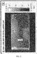
- heat is generally transferred to a battery area by using a graphite sheet or by using a holder material of a higher heat conductivity coefficient, so as to reduce a temperature of an orthogonal projection area of the circuit board of the mobile terminal with respect to the holder. It can be obtained according to FIG. 2 and FIG. 3 that the heat dissipation design reduces a temperature of an area, corresponding to the circuit board, of the mobile terminal, but because of high heat conductivity of the holder, the heat can be more rapidly transferred to the side frame of the mobile terminal; as a result, a large quantity of heat sources are concentrated on the side frame of the mobile terminal (as can be seen in FIG. 2 , a color of this area is relatively bright, which shows that the temperature of this area is relatively high).
- Embodiments of the present invention provide a holder, so as to reduce heat at a side frame of a mobile terminal.
- a holder located in a mobile terminal, where the holder includes a heat conduction area and a heat insulation area, the heat insulation area is close to an edge of the holder, the heat insulation area is adjacent to the heat conduction area, and a heat emitting element in the mobile terminal is proximate to the heat conduction area.
- the mobile terminal includes a side frame, the side frame surrounds the holder, and the heat insulation area isolates the heat emitting element from the side frame.
- the heat insulation area is provided with a heat insulation cavity, and the heat insulation cavity is vacuum or is filled with air.
- the heat insulation area is provided with a heat insulation cavity, the heat insulation cavity has a low heat conduction material, and the low heat conduction material has a heat conductivity coefficient range of 0-0.026 W/m-K.
- the heat insulation cavity is at least one strip-shaped hole or at least one elliptical hole.
- the heat insulation cavity includes at least one groove, and the groove is provided at an edge of the heat insulation area.
- an area of the heat insulation cavity occupies at least 50% of an area of the heat insulation area.
- the heat insulation area is made from a low heat conduction material, and the low heat conduction material has a heat conductivity coefficient range of 0-0.026 W/m-K.
- a material of the holder is a heat conduction material.
- the holder is a display screen holder.
- a mobile terminal including: a side frame, a heat emitting element, and the holder, where the side frame surrounds the holder.
- the heat insulation area is provided on the holder, and the heat insulation area is located at the edge of the holder and is adjacent to the heat conduction area, so that, in a process of transferring heat in the heat conduction area to the side frame, the heat is impeded by the heat insulation area, thereby reducing heat at the side frame.
- a first embodiment of the present invention provides a mobile terminal 100.
- the mobile terminal 100 includes a side frame 2, a heat emitting element 3, and a holder 1.
- the holder 1 is located in the mobile terminal 100, the holder 1 includes a heat conduction area 11 and a heat insulation area 12, the heat insulation area 12 is close to an edge of the holder 1, the heat insulation area 12 is adjacent to the heat conduction area 11, the heat emitting element 3 in the mobile terminal is proximate to the heat conduction area 11, and the side frame 2 surrounds the holder 1.
- the heat insulation area 12 is provided on the holder 1, and the heat insulation area 12 is close to the edge of the holder 1 and is adjacent to the heat conduction area 11, so that, in a process of transferring heat in the heat conduction area 11 to the side frame 2, the heat is impeded by the heat insulation area 12, thereby reducing heat at the side frame 2.
- the heat insulation area 12 may be located between the side frame 2 and the heat conduction area 11.
- the mobile terminal 100 is a smartphone. Certainly, in another embodiment, the mobile terminal 100 may also be a tablet computer.
- the side frame 2 includes a pair of long edges L and a pair of short edges D.
- the heat emitting element 3 is integrated on a circuit board.
- the mobile terminal may include a shielding can, and the shielding can surrounds the heat emitting element 3 on the circuit board, to prevent an electromagnetic field generated by the heat emitting element 3 from diffusing out, and prevent the electromagnetic field from being affected by an outside electromagnetic field.
- stainless steel having a thickness of 0.2 mm and copper-nickel-zinc alloy having a thickness of 0.2 mm may be used as materials of the shielding can.
- the heat conduction medium may be heat conduction silica gel.
- the mobile terminal may not have a shielding can.
- the holder 1 may play a role of a shielding can, that is, prevent the electromagnetic field generated by the heat emitting element 3 from diffusing out, and prevent the electromagnetic field from being affected by an outside electromagnetic field.
- the heat emitting element 3 is close to a right long edge L1 at a right side of the side frame 2, the heat conduction area 11 is generally provided close to the right long edge L1.
- the heat conduction area 11 is relatively near the right long edge L1; therefore, heat is much concentrated at the right long edge L1.
- the heat insulation area 12 is provided close to the right long edge L1.
- the heat insulation area 12 may also be provided between the heat conduction area 11 and the short edge D according to an actual need, or provided between the heat conduction area 11 and the other long edge L; or the heat insulation area 12 may be separately disposed between the heat conduction area 11 and the long edge L and between the heat conduction area 11 and the short edge D.
- the mobile terminal includes the side frame 2, the side frame 2 surrounds the holder 1, and the heat insulation area 12 may completely isolate the heat emitting element 3 from the side frame 2.
- the heat insulation area 12 completely isolates the heat emitting element 3 from the side frame 2, so that when the heat generated by the heat emitting element 3 is transferred to the side frame 2, the heat can pass through the heat insulation area 12, so as to impede all the heat, to improve a heat insulation effect of the heat insulation area 12.
- two ends, oppositely provided along a direction of the long edge L, of the heat insulation area 12 respectively exceed two ends, oppositely provided along the direction of the long edge L, of the heat conduction area 11.
- a size of the heat insulation area along the direction of the long edge L is greater than a size of the heat conduction area 11 along the direction of the long edge L; therefore, when the heat emitting element 3 emits heat and the heat is transferred to the heat conduction area 11, and when the heat in the heat conduction area 11 is transferred to the side frame, the heat passes through the heat insulation area 12, so that the heat insulation area 12 can prevent the heat in the heat conduction area 11.
- the mobile terminal 100 may further perform analysis according to main heat distribution in the heat conduction area 11, and then correspondingly set a size of the heat insulation area 12. That is, a length of the heat insulation area 12 along a length extending direction of the holder 1 is not necessarily greater than a length of the heat conduction area 11 along the holder 1, and may be less than or equal to the length of the heat conduction area 11 along the holder 1, as long as heat reception at a side of the mobile terminal 100 can satisfy an actually needed situation.
- the heat insulation area 12 is provided with a heat insulation cavity 121, and the heat insulation cavity 121 is vacuum or is filled with air 5.
- a heat conductivity coefficient of the air 5 is approximately 0.026 W/m-K in a closed small gap and is far less than that of another material.
- a heat conductivity coefficient of plastic is greater than 0.2 W/m-K
- a heat conductivity coefficient of metal is within 10-400 W/m-K
- a heat conductivity coefficient of glass is approximately 2 W/m-K.
- the materials listed above are generally used to manufacture the holder 1.
- a medium with a relatively small heat conductivity coefficient is introduced to a material with a relatively large heat conductivity coefficient, so that heat resistance is formed at a location at which the medium with the relatively small heat conductivity coefficient is introduced in the holder 1, so as to form the heat insulation area 12.
- heat insulation cavity 121 is filled with the air 5.
- the air 5 exists in the mobile terminal 100.
- the heat insulation cavity 121 may also form heat resistance in another manner.
- the heat insulation cavity 121 is configured to accommodate a low heat conduction material, and the low heat conduction material has a heat conductivity coefficient range of 0-0.026 W/m-K.
- the heat insulation area 12 may be made from a low heat conduction material, and the low heat conduction material has a heat conductivity coefficient range of 0-0.026 W/m-K.
- the heat insulation area 12 is made from a material having a heat conductivity coefficient range of 0-0.26 W/m-K, and a heat conductivity coefficient of a material whose heat conductivity coefficient is within the heat conductivity coefficient range is far less than that of another material.
- metal has a heat conductivity coefficient of 10-400 W/m-K
- glass has a heat conductivity coefficient of approximately 2 W/m-K.
- the materials listed above are generally used to manufacture the holder 1.
- a medium with a relatively small heat conductivity coefficient is introduced to a material with a relatively large heat conductivity coefficient, so that heat resistance is formed at a location at which the medium with the relatively small heat conductivity coefficient is introduced in the holder 1, so as to form the heat insulation area 12.
- the heat insulation cavity 121 is at least one strip-shaped hole or at least one elliptical hole.
- the heat insulation area 12 is provided with the hole-shaped heat insulation cavity 121, so that processing on the holder 1 is relatively simple.
- the heat insulation cavity 121 is at least one strip-shaped hole.
- the heat insulation cavity 121 may also be at least one elliptical hole or a hole of another shape.
- the heat emitting element 3 may be a heating chip and there are three heat insulation cavities 121, which are strip-shaped holes.
- the holes have a length of 5 mm and have a width of 1 mm, and a gap between the holes is greater than 1 mm and less than 2 mm.
- an area of the heat insulation cavity 121 occupies at least 50% of an area of the heat insulation area 12.
- the heat insulation cavity 121 is vacuum or is filled with the air 5, so that a heat-conducting property of the heat insulation cavity 121 becomes poorer, and heat resistance is formed. Therefore, a larger area of the heat insulation cavity 121 indicates a better heat insulation effect of the heat insulation area 12.
- each of the strip-shaped holes has a dimension of 5 mm along the direction of the long edge L (that is, each of the strip-shaped holes has a length of 5 mm along the direction of the long edge L).
- the strip-shaped hole has a dimension of 1 mm along a direction perpendicular to the long edge L (that is, each of the strip-shaped holes has a length of 1 mm along a direction of the short edge).
- a spacing between two neighboring strip-shaped holes is 2 mm.
- the area of the heat insulation cavity 121 occupies approximately 50% of the area of the heat insulation area 12.
- the heat insulation cavity 121 may also be one strip-shaped hole. That is, the area of the heat insulation cavity 121 occupies 100% of the area of the heat insulation area 12, thereby achieving a better heat insulation effect.
- a heat insulation cavity 221 includes at least one groove 221a, where the groove 221a is provided at an edge of a heat insulation area 22.
- An inward dentiform structure is formed at an edge of the heat insulation area 22 because of existence of the groove 221a.
- the heat insulation cavity 221 may include seven grooves 221a.
- Each of the groove 221a has a dimension of 5 mm along the direction of the long edge L (that is, each of the grooves 221a has a length of 5 mm along the direction of the long edge L).
- the groove 221a has a dimension of 1.5 mm along a direction perpendicular to the long edge L (that is, the groove has a length of 1.5 mm along the direction of the short edge).
- a spacing between two neighboring grooves 221a is 2 mm.
- An area of the heat insulation cavity 221 occupies approximately 50% of an area of the heat insulation area 22.
- the heat insulation cavity 221 may also include one groove 221a. That is, the area of the heat insulation cavity 221 occupies 100% of the area of the heat insulation area 22, thereby achieving a better heat insulation effect.
- the heat insulation cavity 221 may also be provided on a same holder 1 in a hole shape and in a form of the groove 221a according to an actual need.
- the material of the holder 1 is a heat conduction material. Heat in the heat emitting element 3 is rapidly transferred to the holder 1 by means of heat conductivity of the holder 1, and then the heat is transferred to the outside of the mobile terminal 100, so that heat dissipation processing on the mobile terminal 100 is more effective.
- the material of the holder 1 may be graphite. When the holder 1 is located between a display screen and the circuit board, heat in the circuit board can be more rapidly transferred to the holder 1.
- the heat in the holder 1 can be more rapidly transferred to the outside of the mobile terminal 100 because of high heat conductivity of the holder 1, so that the heat dissipation processing on the mobile terminal 100 is more effective.
- the material of the holder 1 may also be another material according to an actual need of the mobile terminal 100. For example, if the mobile terminal 100 does not have a relatively high requirement on heat dissipation performance, the material of the holder 1 may also be a material with a relatively low heat-conducting property.
- the heat emitting element 3 When the mobile terminal 100 starts to be equipped, the heat emitting element 3 first needs to be proximate to the heat conduction area 11, and the shielding can and the heat conduction medium are disposed between the heat emitting element 3 and the heat conduction area 11, so as to implement a shielding effect and a heat conduction effect.
- the heat emitting element 3 starts to generate heat, the heat is transferred from the heat emitting element 3 to the holder 1 because of the heat conductivity of the holder 1, and subsequently the holder 1 transfers the heat to the side frame 2 of the mobile terminal 100.
- the holder 1 is a display screen holder.
- the heat insulation area 12 is provided on the holder 1, and the heat insulation area 12 is close to the edge of the holder 1 and is adjacent to the heat conduction area 11, so that, in a process of transferring heat in the heat conduction area 11 to the side frame 2, the heat is impeded by the heat insulation area 12, thereby reducing heat at the side frame 2.
- the heat insulation area 12 completely isolates the heat emitting element 3 from the side frame 2, so that the heat insulation effect of the heat insulation area 12 is improved.
- the heat insulation area 12 is provided with the heat insulation cavity 121, where the heat insulation cavity 121 is vacuum or is filled with the air 5, so that heat insulation is relatively easy to be implemented in the heat insulation area 12.
- the heat insulation area 12 is made from a low heat conduction material, and the low heat conduction material has a thermal insulation coefficient range of 0-0.026 W/m-K, so that the heat insulation effect of the heat insulation area 12 is better.
- the heat insulation cavity 121 is at least one strip-shaped hole or at least one elliptical hole, so that processing on the holder 1 is relatively simple.
- the heat insulation cavity 121 includes at least one groove 221, and the groove 221 is provided at an edge of the heat insulation area 12, so that there are various providing manners for the heat insulation cavity 121.
- the area of the heat insulation cavity 121 occupies at least 50% of the area of the heat insulation area 12, so that the heat insulation effect of the heat insulation area 12 is better.
- the material of the holder 1 is a heat conduction material, so that the heat dissipation processing on the mobile terminal 100 is more effective.
- Embodiment 1 A holder, located in a mobile terminal, wherein the holder comprises a heat conduction area and a heat insulation area, the heat insulation area is close to an edge of the holder, the heat insulation area is adjacent to the heat conduction area, and a heat emitting element in the mobile terminal is proximate to the heat conduction area.
- Embodiment 2 The holder according to embodiment 1, wherein the mobile terminal comprises a side frame, the side frame surrounds the holder, and the heat insulation area isolates the heat emitting element from the side frame.
- Embodiment 3 The holder according to embodiment 1, wherein the heat insulation area is provided with a heat insulation cavity, and the heat insulation cavity is vacuum or is filled with air.
- Embodiment 4 The holder according to embodiment 1, wherein the heat insulation area is provided with a heat insulation cavity, the heat insulation cavity has a low heat conduction material, and the low heat conduction material has a heat conductivity coefficient range of 0-0.026 W/m-K.
- Embodiment 5 The holder according to embodiment 3 or 4, wherein the heat insulation cavity is at least one strip-shaped hole or at least one elliptical hole.
- Embodiment 6 The holder according to embodiment 3 or 4, wherein the heat insulation cavity comprises at least one groove, and the groove is provided at an edge of the heat insulation area.
- Embodiment 7 The holder according to embodiment 3 or 4, wherein an area of the heat insulation cavity occupies at least 50% of an area of the heat insulation area.
- Embodiment 8 The holder according to embodiment 1, wherein the heat insulation area is made from a low heat conduction material, and the low heat conduction material has a heat conductivity coefficient range of 0-0.026 W/m-K.
- Embodiment 9 The holder according to embodiment 1, wherein a material of the holder is a heat conduction material.
- Embodiment 10 The holder according to any one of embodiments 1 to 9, wherein the holder is a display screen holder.
- Embodiment 11 A mobile terminal, comprising: a side frame, a heat emitting element, and the holder according to any one of embodiments 1 to 10, wherein the side frame surrounds the holder.
Landscapes
- Engineering & Computer Science (AREA)
- Theoretical Computer Science (AREA)
- Physics & Mathematics (AREA)
- Computer Hardware Design (AREA)
- Human Computer Interaction (AREA)
- General Engineering & Computer Science (AREA)
- General Physics & Mathematics (AREA)
- Microelectronics & Electronic Packaging (AREA)
- Thermal Sciences (AREA)
- Telephone Set Structure (AREA)
- Cooling Or The Like Of Electrical Apparatus (AREA)
Abstract
Description
- The present invention relates to electronic devices in the communications field, and in particular, to a holder and a mobile terminal having the holder.
- With the rapid development of configurations of mobile terminals, for example, a dominant frequency of an internal chip of the mobile terminal is increasingly high, an access speed of a memory is increasingly high, and correspondingly, radio frequency power amplification and a power management effect are increasingly high, overall heating of the mobile terminal correspondingly increases. Therefore, heat dissipation processing (which is also referred to as a heat dissipation design) on the mobile terminal becomes particularly important. Because of size, waterproof and dustproof, and noise requirements for the mobile terminal, a hermetic seal feature of the mobile terminal restricts using a fan to forcibly dissipate heat. In a case in which the heat can be dissipated only by using a surface of the mobile terminal, performing effective heat dissipation path management by combining a use habit and a heat reception feature becomes a core of the heat dissipation design of the mobile terminal. Research shows that, because the mobile terminal is designed to be thinner, to increase a battery capacity, an overlapping design of a battery and a circuit board becomes a concurrent design on a same plane. Consequently, heat source components (such as the biggest heating component CPU in the mobile terminal) in the mobile terminal are densely centralized in areas corresponding to a side frame and a circuit board that are of the mobile terminal. It can be known according to
FIG. 1 that colors of the two areas in which the heat is relatively concentrated are relatively bright and temperatures are relatively high. However, an area in which heat sources are concentrated is a location that a user often touches when using the mobile terminal. Therefore, more effective heat dissipation processing needs to be performed on the mobile terminal. - In the prior art, heat is generally transferred to a battery area by using a graphite sheet or by using a holder material of a higher heat conductivity coefficient, so as to reduce a temperature of an orthogonal projection area of the circuit board of the mobile terminal with respect to the holder. It can be obtained according to
FIG. 2 andFIG. 3 that the heat dissipation design reduces a temperature of an area, corresponding to the circuit board, of the mobile terminal, but because of high heat conductivity of the holder, the heat can be more rapidly transferred to the side frame of the mobile terminal; as a result, a large quantity of heat sources are concentrated on the side frame of the mobile terminal (as can be seen inFIG. 2 , a color of this area is relatively bright, which shows that the temperature of this area is relatively high). - Embodiments of the present invention provide a holder, so as to reduce heat at a side frame of a mobile terminal.
- According to an aspect, a holder is provided, located in a mobile terminal, where the holder includes a heat conduction area and a heat insulation area, the heat insulation area is close to an edge of the holder, the heat insulation area is adjacent to the heat conduction area, and a heat emitting element in the mobile terminal is proximate to the heat conduction area.
- With reference to the first aspect, in a first possible implementation manner, the mobile terminal includes a side frame, the side frame surrounds the holder, and the heat insulation area isolates the heat emitting element from the side frame.
- With reference to the first aspect, in a second possible implementation manner, the heat insulation area is provided with a heat insulation cavity, and the heat insulation cavity is vacuum or is filled with air.
- With reference to the first aspect, in a third possible implementation manner, the heat insulation area is provided with a heat insulation cavity, the heat insulation cavity has a low heat conduction material, and the low heat conduction material has a heat conductivity coefficient range of 0-0.026 W/m-K.
- With reference to the second possible implementation manner of the first aspect or the third possible implementation manner of the first aspect, in a fourth possible implementation manner, the heat insulation cavity is at least one strip-shaped hole or at least one elliptical hole.
- With reference to the second possible implementation manner of the first aspect or the third possible implementation manner of the first aspect, in a fifth possible implementation manner, the heat insulation cavity includes at least one groove, and the groove is provided at an edge of the heat insulation area.
- With reference to the first aspect, in a sixth possible implementation manner, an area of the heat insulation cavity occupies at least 50% of an area of the heat insulation area.
- With reference to the first aspect, in a seventh possible implementation manner, the heat insulation area is made from a low heat conduction material, and the low heat conduction material has a heat conductivity coefficient range of 0-0.026 W/m-K.
- With reference to the first aspect, in an eighth possible implementation manner, a material of the holder is a heat conduction material.
- With reference to any one of the first aspect to the eighth possible implementation manner, in a ninth possible implementation manner, the holder is a display screen holder.
- According to a second aspect, a mobile terminal is provided, including: a side frame, a heat emitting element, and the holder, where the side frame surrounds the holder.
- According to the holder or the mobile terminal having the holder in the embodiments of the present invention, the heat insulation area is provided on the holder, and the heat insulation area is located at the edge of the holder and is adjacent to the heat conduction area, so that, in a process of transferring heat in the heat conduction area to the side frame, the heat is impeded by the heat insulation area, thereby reducing heat at the side frame.
- To describe the technical solutions in the embodiments of the present invention more clearly, the following briefly describes the accompanying drawings required for describing the embodiments. Apparently, the accompanying drawings in the following description show merely some embodiments of the present invention, and persons of ordinary skill in the art may still derive other drawings from these accompanying drawings without creative efforts.
-
FIG. 1 andFIG. 2 are schematic diagrams of infrared temperature distribution of a front plane and a rear plane that are of a mobile terminal in the prior art; -
FIG. 3 is a schematic diagram of infrared temperature distribution of a front plane and a rear plane that are of another mobile terminal in the prior art; -
FIG. 4 is a schematic diagram of a mobile terminal according toEmbodiment 1 of the present invention; -
FIG. 5 is a schematic diagram of a holder inFIG. 4 ; -
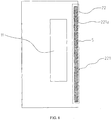
FIG. 6 is a schematic diagram of another holder inFIG. 4 ; -
FIG. 7 is a schematic diagram of a holder according toEmbodiment 2 of the present invention; -
FIG. 8 is a schematic diagram of another holder provided inFIG. 7 ; and -
FIG. 9 is a schematic diagram of temperature distribution of the mobile terminal inFIG. 4 . - The following clearly and completely describes the technical solutions in the embodiments of the present invention with reference to the accompanying drawings in the embodiments of the present invention. Apparently, the described embodiments are merely some but not all of the embodiments of the present invention. All other embodiments obtained by persons of ordinary skill in the art based on the embodiments of the present invention without creative efforts shall fall within the protection scope of the present invention.
- Referring to
FIG. 4 andFIG. 5 , a first embodiment of the present invention provides amobile terminal 100. Themobile terminal 100 includes aside frame 2, aheat emitting element 3, and aholder 1. Theholder 1 is located in themobile terminal 100, theholder 1 includes aheat conduction area 11 and aheat insulation area 12, theheat insulation area 12 is close to an edge of theholder 1, theheat insulation area 12 is adjacent to theheat conduction area 11, theheat emitting element 3 in the mobile terminal is proximate to theheat conduction area 11, and theside frame 2 surrounds theholder 1. - According to the
mobile terminal 100 provided in this embodiment of the present invention, theheat insulation area 12 is provided on theholder 1, and theheat insulation area 12 is close to the edge of theholder 1 and is adjacent to theheat conduction area 11, so that, in a process of transferring heat in theheat conduction area 11 to theside frame 2, the heat is impeded by theheat insulation area 12, thereby reducing heat at theside frame 2. - The
heat insulation area 12 may be located between theside frame 2 and theheat conduction area 11. - In this embodiment, the
mobile terminal 100 is a smartphone. Certainly, in another embodiment, themobile terminal 100 may also be a tablet computer. - In this embodiment, the
side frame 2 includes a pair of long edges L and a pair of short edges D. When a user uses themobile terminal 100, the user generally holds the pair of long edges L. Theheat emitting element 3 is integrated on a circuit board. The mobile terminal may include a shielding can, and the shielding can surrounds theheat emitting element 3 on the circuit board, to prevent an electromagnetic field generated by theheat emitting element 3 from diffusing out, and prevent the electromagnetic field from being affected by an outside electromagnetic field. Optionally, stainless steel having a thickness of 0.2 mm and copper-nickel-zinc alloy having a thickness of 0.2 mm may be used as materials of the shielding can. There may be a heat conduction medium between the shielding can and theheat emitting element 3. - There may also be a heat conduction medium on the shielding can, the heat conduction medium is proximate to the
heat conduction area 11, and theheat emitting element 3 is proximate to theheat conduction area 11, so that heat generated by theheat emitting element 3 can be more rapidly transferred to theholder 1. The heat may be transferred to the outside of themobile terminal 100 by using theholder 1. The heat conduction medium may be heat conduction silica gel. - It can be understood that the mobile terminal may not have a shielding can. The
holder 1 may play a role of a shielding can, that is, prevent the electromagnetic field generated by theheat emitting element 3 from diffusing out, and prevent the electromagnetic field from being affected by an outside electromagnetic field. - In this embodiment, the
heat emitting element 3 is close to a right long edge L1 at a right side of theside frame 2, theheat conduction area 11 is generally provided close to the right long edge L1. Theheat conduction area 11 is relatively near the right long edge L1; therefore, heat is much concentrated at the right long edge L1. To improve this situation, theheat insulation area 12 is provided close to the right long edge L1. Certainly, in another embodiment, theheat insulation area 12 may also be provided between theheat conduction area 11 and the short edge D according to an actual need, or provided between theheat conduction area 11 and the other long edge L; or theheat insulation area 12 may be separately disposed between theheat conduction area 11 and the long edge L and between theheat conduction area 11 and the short edge D. - For further improvement, the mobile terminal includes the
side frame 2, theside frame 2 surrounds theholder 1, and theheat insulation area 12 may completely isolate theheat emitting element 3 from theside frame 2. Theheat insulation area 12 completely isolates theheat emitting element 3 from theside frame 2, so that when the heat generated by theheat emitting element 3 is transferred to theside frame 2, the heat can pass through theheat insulation area 12, so as to impede all the heat, to improve a heat insulation effect of theheat insulation area 12. - In this embodiment, two ends, oppositely provided along a direction of the long edge L, of the
heat insulation area 12 respectively exceed two ends, oppositely provided along the direction of the long edge L, of theheat conduction area 11. A size of the heat insulation area along the direction of the long edge L is greater than a size of theheat conduction area 11 along the direction of the long edge L; therefore, when theheat emitting element 3 emits heat and the heat is transferred to theheat conduction area 11, and when the heat in theheat conduction area 11 is transferred to the side frame, the heat passes through theheat insulation area 12, so that theheat insulation area 12 can prevent the heat in theheat conduction area 11. Certainly, in another embodiment, themobile terminal 100 may further perform analysis according to main heat distribution in theheat conduction area 11, and then correspondingly set a size of theheat insulation area 12. That is, a length of theheat insulation area 12 along a length extending direction of theholder 1 is not necessarily greater than a length of theheat conduction area 11 along theholder 1, and may be less than or equal to the length of theheat conduction area 11 along theholder 1, as long as heat reception at a side of themobile terminal 100 can satisfy an actually needed situation. - For further improvement, referring to
FIG. 5 , theheat insulation area 12 is provided with aheat insulation cavity 121, and theheat insulation cavity 121 is vacuum or is filled withair 5. A heat conductivity coefficient of theair 5 is approximately 0.026 W/m-K in a closed small gap and is far less than that of another material. For example, a heat conductivity coefficient of plastic is greater than 0.2 W/m-K, a heat conductivity coefficient of metal is within 10-400 W/m-K, and a heat conductivity coefficient of glass is approximately 2 W/m-K. The materials listed above are generally used to manufacture theholder 1. A medium with a relatively small heat conductivity coefficient is introduced to a material with a relatively large heat conductivity coefficient, so that heat resistance is formed at a location at which the medium with the relatively small heat conductivity coefficient is introduced in theholder 1, so as to form theheat insulation area 12. As vacuum is not heat-conductive, or theair 5 in the cavity has a small heat conductivity coefficient, heat resistance is formed at the location at which the medium of the relatively small heat conductivity coefficient is introduced in theholder 1, so that the heat insulation effect is better. In this embodiment, theheat insulation cavity 121 is filled with theair 5. Generally, in the prior art, theair 5 exists in themobile terminal 100. To enable theheat insulation cavity 121 to have the heat insulation effect, making theheat insulation cavity 121 have theair 5 is a relatively easy way, or the interior of themobile terminal 100 may be made to be in a vacuum environment to make theheat insulation cavity 121 be vacuum. Certainly, in another embodiment, theheat insulation cavity 121 may also form heat resistance in another manner. For example, theheat insulation cavity 121 is configured to accommodate a low heat conduction material, and the low heat conduction material has a heat conductivity coefficient range of 0-0.026 W/m-K. In another embodiment, theheat insulation area 12 may be made from a low heat conduction material, and the low heat conduction material has a heat conductivity coefficient range of 0-0.026 W/m-K. Theheat insulation area 12 is made from a material having a heat conductivity coefficient range of 0-0.26 W/m-K, and a heat conductivity coefficient of a material whose heat conductivity coefficient is within the heat conductivity coefficient range is far less than that of another material. For example, metal has a heat conductivity coefficient of 10-400 W/m-K, and glass has a heat conductivity coefficient of approximately 2 W/m-K. The materials listed above are generally used to manufacture theholder 1. A medium with a relatively small heat conductivity coefficient is introduced to a material with a relatively large heat conductivity coefficient, so that heat resistance is formed at a location at which the medium with the relatively small heat conductivity coefficient is introduced in theholder 1, so as to form theheat insulation area 12. - For further improvement, the
heat insulation cavity 121 is at least one strip-shaped hole or at least one elliptical hole. Theheat insulation area 12 is provided with the hole-shapedheat insulation cavity 121, so that processing on theholder 1 is relatively simple. In this embodiment, theheat insulation cavity 121 is at least one strip-shaped hole. Certainly, in another embodiment, theheat insulation cavity 121 may also be at least one elliptical hole or a hole of another shape. - The
heat emitting element 3 may be a heating chip and there are threeheat insulation cavities 121, which are strip-shaped holes. The holes have a length of 5 mm and have a width of 1 mm, and a gap between the holes is greater than 1 mm and less than 2 mm. - For further improvement, an area of the
heat insulation cavity 121 occupies at least 50% of an area of theheat insulation area 12. Theheat insulation cavity 121 is vacuum or is filled with theair 5, so that a heat-conducting property of theheat insulation cavity 121 becomes poorer, and heat resistance is formed. Therefore, a larger area of theheat insulation cavity 121 indicates a better heat insulation effect of theheat insulation area 12. - In this embodiment, in consideration of general strength of the material of the
holder 1, there are sevenheat insulation cavities 121, which are strip-shaped holes. Each of the strip-shaped holes has a dimension of 5 mm along the direction of the long edge L (that is, each of the strip-shaped holes has a length of 5 mm along the direction of the long edge L). The strip-shaped hole has a dimension of 1 mm along a direction perpendicular to the long edge L (that is, each of the strip-shaped holes has a length of 1 mm along a direction of the short edge). A spacing between two neighboring strip-shaped holes is 2 mm. The area of theheat insulation cavity 121 occupies approximately 50% of the area of theheat insulation area 12. - Referring to
FIG. 6 , when the strength of theholder 1 is higher, theheat insulation cavity 121 may also be one strip-shaped hole. That is, the area of theheat insulation cavity 121 occupies 100% of the area of theheat insulation area 12, thereby achieving a better heat insulation effect. - Certainly, in a second embodiment, as shown in
FIG. 7 , aheat insulation cavity 221 includes at least onegroove 221a, where thegroove 221a is provided at an edge of aheat insulation area 22. An inward dentiform structure is formed at an edge of theheat insulation area 22 because of existence of thegroove 221a. In consideration of strength of a material of theholder 1, theheat insulation cavity 221 may include sevengrooves 221a. Each of thegroove 221a has a dimension of 5 mm along the direction of the long edge L (that is, each of thegrooves 221a has a length of 5 mm along the direction of the long edge L). Thegroove 221a has a dimension of 1.5 mm along a direction perpendicular to the long edge L (that is, the groove has a length of 1.5 mm along the direction of the short edge). A spacing between twoneighboring grooves 221a is 2 mm. An area of theheat insulation cavity 221 occupies approximately 50% of an area of theheat insulation area 22. - As shown in
FIG. 8 , when the strength of theholder 1 is higher, theheat insulation cavity 221 may also include onegroove 221a. That is, the area of theheat insulation cavity 221 occupies 100% of the area of theheat insulation area 22, thereby achieving a better heat insulation effect. In another embodiment, theheat insulation cavity 221 may also be provided on asame holder 1 in a hole shape and in a form of thegroove 221a according to an actual need. - Referring to
FIG. 9 , for a heat distribution status after theholder 1 is provided with theheat insulation cavity 121. Heat in themobile terminal 100 is evenly distributed, and the heat is not concentrated on theside frame 2 of themobile terminal 100. - For further improvement, the material of the
holder 1 is a heat conduction material. Heat in theheat emitting element 3 is rapidly transferred to theholder 1 by means of heat conductivity of theholder 1, and then the heat is transferred to the outside of themobile terminal 100, so that heat dissipation processing on themobile terminal 100 is more effective. In this embodiment, to ensure a heat-conducting property of theholder 1, the material of theholder 1 may be graphite. When theholder 1 is located between a display screen and the circuit board, heat in the circuit board can be more rapidly transferred to theholder 1. In addition, the heat in theholder 1 can be more rapidly transferred to the outside of themobile terminal 100 because of high heat conductivity of theholder 1, so that the heat dissipation processing on themobile terminal 100 is more effective. Certainly, in another embodiment, the material of theholder 1 may also be another material according to an actual need of themobile terminal 100. For example, if themobile terminal 100 does not have a relatively high requirement on heat dissipation performance, the material of theholder 1 may also be a material with a relatively low heat-conducting property. - When the mobile terminal 100 starts to be equipped, the
heat emitting element 3 first needs to be proximate to theheat conduction area 11, and the shielding can and the heat conduction medium are disposed between theheat emitting element 3 and theheat conduction area 11, so as to implement a shielding effect and a heat conduction effect. When theheat emitting element 3 starts to generate heat, the heat is transferred from theheat emitting element 3 to theholder 1 because of the heat conductivity of theholder 1, and subsequently theholder 1 transfers the heat to theside frame 2 of themobile terminal 100. In a process of transferring the heat in theheat conduction area 11 to the side, because of the existence of theheat insulation area 12, the heat is impeded by heat resistance formed in theheat insulation area 12, so that heat at the side is relatively low, thereby ensuring that the heat at theside frame 2 of a housing of themobile terminal 100 is relatively low. - The
holder 1 is a display screen holder. - According to the
mobile terminal 100 provided in this embodiment of the present invention, theheat insulation area 12 is provided on theholder 1, and theheat insulation area 12 is close to the edge of theholder 1 and is adjacent to theheat conduction area 11, so that, in a process of transferring heat in theheat conduction area 11 to theside frame 2, the heat is impeded by theheat insulation area 12, thereby reducing heat at theside frame 2. - In addition, the
heat insulation area 12 completely isolates theheat emitting element 3 from theside frame 2, so that the heat insulation effect of theheat insulation area 12 is improved. Theheat insulation area 12 is provided with theheat insulation cavity 121, where theheat insulation cavity 121 is vacuum or is filled with theair 5, so that heat insulation is relatively easy to be implemented in theheat insulation area 12. Theheat insulation area 12 is made from a low heat conduction material, and the low heat conduction material has a thermal insulation coefficient range of 0-0.026 W/m-K, so that the heat insulation effect of theheat insulation area 12 is better. Theheat insulation cavity 121 is at least one strip-shaped hole or at least one elliptical hole, so that processing on theholder 1 is relatively simple. Theheat insulation cavity 121 includes at least onegroove 221, and thegroove 221 is provided at an edge of theheat insulation area 12, so that there are various providing manners for theheat insulation cavity 121. The area of theheat insulation cavity 121 occupies at least 50% of the area of theheat insulation area 12, so that the heat insulation effect of theheat insulation area 12 is better. The material of theholder 1 is a heat conduction material, so that the heat dissipation processing on themobile terminal 100 is more effective. - Further embodiments of the present invention are provided in the following. It should be noted that the numbering used in the following section does not necessarily need to comply with the numbering used in the previous sections.
-
Embodiment 1. A holder, located in a mobile terminal, wherein the holder comprises a heat conduction area and a heat insulation area, the heat insulation area is close to an edge of the holder, the heat insulation area is adjacent to the heat conduction area, and a heat emitting element in the mobile terminal is proximate to the heat conduction area. -
Embodiment 2. The holder according toembodiment 1, wherein the mobile terminal comprises a side frame, the side frame surrounds the holder, and the heat insulation area isolates the heat emitting element from the side frame. -
Embodiment 3. The holder according toembodiment 1, wherein the heat insulation area is provided with a heat insulation cavity, and the heat insulation cavity is vacuum or is filled with air. - Embodiment 4. The holder according to
embodiment 1, wherein the heat insulation area is provided with a heat insulation cavity, the heat insulation cavity has a low heat conduction material, and the low heat conduction material has a heat conductivity coefficient range of 0-0.026 W/m-K. -
Embodiment 5. The holder according toembodiment 3 or 4, wherein the heat insulation cavity is at least one strip-shaped hole or at least one elliptical hole. - Embodiment 6. The holder according to
embodiment 3 or 4, wherein the heat insulation cavity comprises at least one groove, and the groove is provided at an edge of the heat insulation area. - Embodiment 7. The holder according to
embodiment 3 or 4, wherein an area of the heat insulation cavity occupies at least 50% of an area of the heat insulation area. -
Embodiment 8. The holder according toembodiment 1, wherein the heat insulation area is made from a low heat conduction material, and the low heat conduction material has a heat conductivity coefficient range of 0-0.026 W/m-K. - Embodiment 9. The holder according to
embodiment 1, wherein a material of the holder is a heat conduction material. - Embodiment 10. The holder according to any one of
embodiments 1 to 9, wherein the holder is a display screen holder. -
Embodiment 11. A mobile terminal, comprising: a side frame, a heat emitting element, and the holder according to any one ofembodiments 1 to 10, wherein the side frame surrounds the holder. - Finally, it should be noted that the foregoing embodiments are merely intended for describing the technical solutions of the present invention but not for limiting the present invention. Although the present invention is described in detail with reference to the foregoing embodiments, persons of ordinary skill in the art should understand that they may still make modifications to the technical solutions described in the foregoing embodiments or make equivalent replacements to some technical features thereof, without departing from the spirit and scope of the technical solutions of the embodiments of the present invention.
Claims (13)
- A holder, located in a mobile terminal, wherein the holder comprises a heat conduction area and a heat insulation area, the heat insulation area is close to an edge of the holder, the heat insulation area is adjacent to the heat conduction area, and a heat emitting element on a circuit board is proximate to the heat conduction area, the holder is located between a display screen of the mobile terminal and the circuit board.
- The holder according to claim 1, wherein the mobile terminal comprises a side frame, the side frame surrounds the holder.
- The holder according to claim 1 or 2, wherein the heat insulation area is provided with a heat insulation cavity, and the heat insulation cavity is vacuum or is filled with air.
- The holder according to claim 1 or 2, wherein the heat insulation area is provided with a heat insulation cavity, the heat insulation cavity is configured to accommodate a low heat conduction material, and the low heat conduction material has a heat conductivity coefficient range of 0-0.026 W/m-K.
- The holder according to claim 3 or 4, wherein the heat insulation cavity is at least one strip-shaped hole or at least one elliptical hole.
- The holder according to any one of claims 3-5, wherein an area of the heat insulation cavity occupies at least 50% of an area of the heat insulation area.
- The holder according to any one of claims 1-3 and 5-6, wherein the heat insulation area is made from a low heat conduction material, and the low heat conduction material has a heat conductivity coefficient range of 0-0.026 W/m-K.
- The holder according to any one of claims 1-7, wherein a material of the heat conduction area is metal material or glass material or graphite material.
- The holder according to any one of claims 1-8, wherein the holder is the display screen holder.
- The holder according to any one of claims 1-9, wherein the heat insulation area is located between the side frame and the heat conduction area.
- A mobile terminal, comprising a holder according to any one of claims 1 to 10.
- The terminal according to claim 11, wherein the mobile terminal further comprises a shielding can, the shielding surrounds the heat emitting element.
- The mobile terminal according to claim 11 or 12, wherein the mobile terminal is a phone.
Priority Applications (1)
| Application Number | Priority Date | Filing Date | Title |
|---|---|---|---|
| EP18182424.4A EP3461248B1 (en) | 2014-03-21 | 2014-03-21 | Mobile terminal |
Applications Claiming Priority (3)
| Application Number | Priority Date | Filing Date | Title |
|---|---|---|---|
| PCT/CN2014/073815 WO2015139285A1 (en) | 2014-03-21 | 2014-03-21 | Frame and mobile terminal |
| EP18182424.4A EP3461248B1 (en) | 2014-03-21 | 2014-03-21 | Mobile terminal |
| EP14886101.6A EP3107362B1 (en) | 2014-03-21 | 2014-03-21 | Frame and mobile terminal |
Related Parent Applications (2)
| Application Number | Title | Priority Date | Filing Date |
|---|---|---|---|
| EP14886101.6A Division EP3107362B1 (en) | 2014-03-21 | 2014-03-21 | Frame and mobile terminal |
| EP14886101.6A Division-Into EP3107362B1 (en) | 2014-03-21 | 2014-03-21 | Frame and mobile terminal |
Publications (2)
| Publication Number | Publication Date |
|---|---|
| EP3461248A1 true EP3461248A1 (en) | 2019-03-27 |
| EP3461248B1 EP3461248B1 (en) | 2022-07-06 |
Family
ID=54143701
Family Applications (2)
| Application Number | Title | Priority Date | Filing Date |
|---|---|---|---|
| EP18182424.4A Active EP3461248B1 (en) | 2014-03-21 | 2014-03-21 | Mobile terminal |
| EP14886101.6A Active EP3107362B1 (en) | 2014-03-21 | 2014-03-21 | Frame and mobile terminal |
Family Applications After (1)
| Application Number | Title | Priority Date | Filing Date |
|---|---|---|---|
| EP14886101.6A Active EP3107362B1 (en) | 2014-03-21 | 2014-03-21 | Frame and mobile terminal |
Country Status (6)
| Country | Link |
|---|---|
| US (2) | US9910468B2 (en) |
| EP (2) | EP3461248B1 (en) |
| JP (1) | JP6397045B2 (en) |
| KR (2) | KR102089472B1 (en) |
| CN (2) | CN108055815B (en) |
| WO (1) | WO2015139285A1 (en) |
Families Citing this family (7)
| Publication number | Priority date | Publication date | Assignee | Title |
|---|---|---|---|---|
| KR102483238B1 (en) * | 2016-08-01 | 2022-12-30 | 삼성전자 주식회사 | Heat dissipation apparatus and electronic device having the same |
| KR102709687B1 (en) * | 2017-01-06 | 2024-09-26 | 삼성전자주식회사 | Heat-radiating structure and Electronic Device including thereof |
| CN106879226A (en) * | 2017-01-20 | 2017-06-20 | 努比亚技术有限公司 | A kind of device and electronic equipment of control case temperature |
| EP3579673B1 (en) * | 2017-03-02 | 2022-01-26 | Huawei Technologies Co., Ltd. | Thermally-conductive component and mobile terminal |
| CN107592763A (en) * | 2017-09-29 | 2018-01-16 | 深圳传音制造有限公司 | A kind of heat insulation structural, mobile terminal and heat-insulating method |
| CN110691156A (en) * | 2019-11-06 | 2020-01-14 | 北京字节跳动网络技术有限公司 | Support for electronic equipment and electronic equipment |
| WO2025028775A1 (en) * | 2023-08-02 | 2025-02-06 | 삼성전자주식회사 | Wearable device comprising insulation structure |
Citations (4)
| Publication number | Priority date | Publication date | Assignee | Title |
|---|---|---|---|---|
| EP1233666A1 (en) * | 2000-06-06 | 2002-08-21 | Mitsubishi Denki Kabushiki Kaisha | Cooling structure of communication device |
| CN201115242Y (en) * | 2007-09-20 | 2008-09-10 | 深圳华为通信技术有限公司 | Electronic product heat radiation device based on user satisfaction |
| US20130301221A1 (en) * | 2013-03-07 | 2013-11-14 | Jones Tech Plc. | Thermal management system and method between heat generating chip and housing in electronic apparatus |
| WO2013191493A1 (en) * | 2012-06-20 | 2013-12-27 | Lg Electronics Inc. | Terminal unit |
Family Cites Families (55)
| Publication number | Priority date | Publication date | Assignee | Title |
|---|---|---|---|---|
| JP2997273B2 (en) | 1989-05-29 | 2000-01-11 | 西部電機株式会社 | Stage movable support device |
| JPH0498030U (en) * | 1991-01-12 | 1992-08-25 | ||
| US5581443A (en) | 1994-09-14 | 1996-12-03 | Kabushiki Kaisha Toshiba | Structure for cooling a circuit module having a circuit board and a heat-generating IC chip mounted on the board, and portable electronic apparatus incorporating the structure |
| JP3876491B2 (en) * | 1997-02-27 | 2007-01-31 | 三菱電機株式会社 | Vacuum insulation panel, method for manufacturing the same, and refrigerator using the same |
| JPH11143584A (en) * | 1997-11-07 | 1999-05-28 | Pfu Ltd | Heat dissipation structure of portable terminal device |
| JP3601282B2 (en) | 1998-01-20 | 2004-12-15 | 株式会社日立製作所 | Notebook computer |
| JP3366244B2 (en) * | 1998-02-04 | 2003-01-14 | 富士通株式会社 | Electronics |
| JP3656822B2 (en) * | 1999-09-03 | 2005-06-08 | 松下電器産業株式会社 | Portable information processing device |
| US6414844B1 (en) | 1999-09-03 | 2002-07-02 | Matsushita Electric Industrial Co., Ltd. | Portable information processing apparatus |
| TW470837B (en) * | 2000-04-21 | 2002-01-01 | Matsushita Refrigeration | Vacuum heat insulator |
| JP2001308137A (en) * | 2000-04-26 | 2001-11-02 | Matsushita Electric Works Ltd | Semiconductor device and manufacturing method thereof |
| EP1288770B1 (en) * | 2000-06-06 | 2009-03-04 | Panasonic Corporation | Portable information appliance |
| JP2003188323A (en) | 2001-12-19 | 2003-07-04 | Sony Corp | Graphite sheet and method for producing the same |
| US20030161132A1 (en) | 2002-02-05 | 2003-08-28 | Mitsubishi Denki Kabushiki Kaisha | Communication device |
| JP3559035B2 (en) * | 2002-12-05 | 2004-08-25 | 松下冷機株式会社 | Vacuum insulation material, method of manufacturing the same, and cold protection equipment and personal computer using vacuum insulation material |
| US7188484B2 (en) | 2003-06-09 | 2007-03-13 | Lg Electronics Inc. | Heat dissipating structure for mobile device |
| US7292441B2 (en) | 2003-11-25 | 2007-11-06 | Advanced Energy Technology Inc. | Thermal solution for portable electronic devices |
| JP2005277163A (en) * | 2004-03-25 | 2005-10-06 | Kyocera Corp | Wiring board |
| JP2006165154A (en) * | 2004-12-06 | 2006-06-22 | Matsushita Electric Ind Co Ltd | Thermal conduction member |
| CN100543353C (en) * | 2004-12-07 | 2009-09-23 | 松下电器产业株式会社 | Vacuum heat insulating material, manufacturing method thereof, and heat insulating box using same |
| JP4487799B2 (en) * | 2005-02-25 | 2010-06-23 | 株式会社日立製作所 | Constant temperature transport container |
| CA2877959C (en) * | 2006-08-22 | 2017-06-13 | Charles F. Barry | Apparatus and method for thermal stabilization of pcb-mounted electronic components within an enclosed housing |
| JP5179746B2 (en) | 2006-11-22 | 2013-04-10 | 京セラ株式会社 | Mobile terminal device |
| US7486517B2 (en) * | 2006-12-20 | 2009-02-03 | Nokia Corporation | Hand-held portable electronic device having a heat spreader |
| EP2075993A4 (en) * | 2007-07-02 | 2009-12-02 | Huawei Tech Co Ltd | A mobile terminal preventing temperature rising of user-sensitive surface |
| CN201114231Y (en) * | 2007-07-02 | 2008-09-10 | 华为技术有限公司 | A mobile terminal that prevents the temperature rise of the user's sensitive surface |
| CN201278544Y (en) * | 2008-09-12 | 2009-07-22 | 中兴通讯股份有限公司 | Wireless communication terminal module |
| KR101179364B1 (en) | 2008-09-22 | 2012-09-03 | 파나소닉 주식회사 | Portable Electronic Device |
| JP2010165728A (en) * | 2009-01-13 | 2010-07-29 | Kyocera Corp | Multilayer substrate and portable communication device |
| JP2010251386A (en) | 2009-04-10 | 2010-11-04 | Nec Corp | Electronic apparatus with thermal diffusion member, method of manufacturing electronic apparatus with thermal diffusion member, and thermal diffusion member |
| JP5327024B2 (en) * | 2009-12-03 | 2013-10-30 | 三菱エンジニアリングプラスチックス株式会社 | Two-color molded product with heat dissipation part and equipment with heating element |
| CN201550395U (en) * | 2009-12-10 | 2010-08-11 | 华为终端有限公司 | Wireless terminal and housing |
| US8391010B2 (en) * | 2010-08-19 | 2013-03-05 | Apple Inc. | Internal frame optimized for stiffness and heat transfer |
| JP2011042575A (en) | 2010-11-22 | 2011-03-03 | Nichias Corp | Inorganic fibrous molded body and method for producing the same |
| US8537553B2 (en) | 2011-02-14 | 2013-09-17 | Futurewei Technologies, Inc. | Devices having anisotropic conductivity heatsinks, and methods of making thereof |
| CN202003615U (en) * | 2011-03-14 | 2011-10-05 | 华为终端有限公司 | Heat radiating device for display screen |
| EP2661164A4 (en) * | 2011-06-14 | 2015-03-25 | Huawei Device Co Ltd | DEVICE WITH THERMAL INSULATION STRUCTURE |
| WO2013018553A1 (en) | 2011-07-29 | 2013-02-07 | 日本電気株式会社 | Mobile electronic device |
| CN102427159A (en) * | 2011-08-12 | 2012-04-25 | 华为终端有限公司 | Wireless terminal and antenna frame thereof |
| JP5067497B2 (en) * | 2011-09-28 | 2012-11-07 | 富士通株式会社 | Display device, display panel unit, and information processing device |
| CN202335181U (en) * | 2011-10-11 | 2012-07-11 | 捷开通讯科技(上海)有限公司 | Electronic device and heat dissipation structure therefor |
| DE102011117490A1 (en) * | 2011-10-27 | 2013-05-02 | Asia Vital Components Co., Ltd. | Vapor-chamber cooler and method for its production |
| US20140355194A1 (en) | 2012-01-16 | 2014-12-04 | Nec Casio Mobile Communications, Ltd. | Portable terminal device |
| EP2806419A4 (en) | 2012-01-16 | 2015-12-23 | Nec Corp | Mobile terminal device |
| JP2013150067A (en) | 2012-01-17 | 2013-08-01 | Kyocera Corp | Portable terminal cover |
| JP2013214868A (en) * | 2012-04-02 | 2013-10-17 | Sharp Corp | Portable information terminal |
| CN102711416B (en) * | 2012-05-24 | 2015-10-21 | 中兴通讯股份有限公司 | Radiating treatment device and mobile terminal |
| CN203086894U (en) * | 2012-12-31 | 2013-07-24 | 青岛海信移动通信技术股份有限公司 | Thermal insulation metal casing and portable mobile terminal |
| CN103209574B (en) * | 2013-04-24 | 2017-04-12 | 惠州Tcl移动通信有限公司 | Heat dissipation device and method of mobile terminal, and mobile terminal |
| CN203327471U (en) | 2013-07-23 | 2013-12-04 | 奇鋐科技股份有限公司 | Heat dissipation structure and handheld electronic device with the heat dissipation structure |
| CN105830548B (en) * | 2013-10-31 | 2017-12-01 | 阿莫绿色技术有限公司 | Thermal component and there is its portable terminal |
| US10019046B2 (en) * | 2015-08-17 | 2018-07-10 | Asia Vital Components Co., Ltd. | Internal frame structure with heat insulation effect and electronic apparatus with the internal frame structure |
| US9578791B1 (en) * | 2015-08-17 | 2017-02-21 | Asia Vital Components Co., Ltd. | Internal frame structure with heat isolation effect and electronic apparatus with the internal frame structure |
| US9690341B2 (en) * | 2015-09-04 | 2017-06-27 | Asia Vital Components Co., Ltd. | Heat insulation structure for hand-held device and hand-held device with same |
| KR102483238B1 (en) * | 2016-08-01 | 2022-12-30 | 삼성전자 주식회사 | Heat dissipation apparatus and electronic device having the same |
-
2014
- 2014-03-21 CN CN201810011916.5A patent/CN108055815B/en active Active
- 2014-03-21 KR KR1020167027927A patent/KR102089472B1/en active Active
- 2014-03-21 JP JP2016557014A patent/JP6397045B2/en active Active
- 2014-03-21 WO PCT/CN2014/073815 patent/WO2015139285A1/en not_active Ceased
- 2014-03-21 KR KR1020187025285A patent/KR101953333B1/en active Active
- 2014-03-21 US US15/127,705 patent/US9910468B2/en active Active
- 2014-03-21 EP EP18182424.4A patent/EP3461248B1/en active Active
- 2014-03-21 CN CN201480005568.0A patent/CN105611984B/en active Active
- 2014-03-21 EP EP14886101.6A patent/EP3107362B1/en active Active
-
2018
- 2018-01-23 US US15/878,017 patent/US10481654B2/en active Active
Patent Citations (4)
| Publication number | Priority date | Publication date | Assignee | Title |
|---|---|---|---|---|
| EP1233666A1 (en) * | 2000-06-06 | 2002-08-21 | Mitsubishi Denki Kabushiki Kaisha | Cooling structure of communication device |
| CN201115242Y (en) * | 2007-09-20 | 2008-09-10 | 深圳华为通信技术有限公司 | Electronic product heat radiation device based on user satisfaction |
| WO2013191493A1 (en) * | 2012-06-20 | 2013-12-27 | Lg Electronics Inc. | Terminal unit |
| US20130301221A1 (en) * | 2013-03-07 | 2013-11-14 | Jones Tech Plc. | Thermal management system and method between heat generating chip and housing in electronic apparatus |
Also Published As
| Publication number | Publication date |
|---|---|
| US20170139452A1 (en) | 2017-05-18 |
| EP3461248B1 (en) | 2022-07-06 |
| KR101953333B1 (en) | 2019-02-28 |
| US9910468B2 (en) | 2018-03-06 |
| JP6397045B2 (en) | 2018-09-26 |
| US20180150115A1 (en) | 2018-05-31 |
| EP3107362B1 (en) | 2018-09-19 |
| JP2017511643A (en) | 2017-04-20 |
| KR102089472B1 (en) | 2020-03-16 |
| EP3107362A4 (en) | 2016-12-28 |
| KR20180100274A (en) | 2018-09-07 |
| WO2015139285A1 (en) | 2015-09-24 |
| CN108055815B (en) | 2020-04-21 |
| US10481654B2 (en) | 2019-11-19 |
| CN108055815A (en) | 2018-05-18 |
| CN105611984B (en) | 2018-01-16 |
| EP3107362A1 (en) | 2016-12-21 |
| KR20160130845A (en) | 2016-11-14 |
| CN105611984A (en) | 2016-05-25 |
Similar Documents
| Publication | Publication Date | Title |
|---|---|---|
| US10481654B2 (en) | Holder and mobile terminal | |
| US20190045674A1 (en) | Electromagnetic shielding structure and electronic device having the same | |
| US20160266622A1 (en) | Mobile Terminal Heat Dissipation Apparatus and Shielding Cover Frame | |
| US20170105315A1 (en) | Heat conductive plastic radiator and communicaiton device | |
| WO2016179915A1 (en) | Mobile communication terminal | |
| US9244505B2 (en) | Portable electronic device with exposed heat dissipating mechanism | |
| CN104619146A (en) | Heat radiating device and electronic equipment | |
| CN102711416B (en) | Radiating treatment device and mobile terminal | |
| CN203645968U (en) | Optical module heat dissipation apparatus | |
| EP3163987A1 (en) | Noise reduction apparatus and method | |
| TW201508453A (en) | heat sink | |
| JP6591013B2 (en) | mobile computer | |
| CN205305289U (en) | Type of putting on shelf totally -enclosed formula codec | |
| JP2011066039A (en) | Radio communication device | |
| CN205052045U (en) | Cooling system of on -vehicle product | |
| CN203015353U (en) | Wireless audio and video communication device | |
| CN107864600B (en) | Heat abstractor and desk-top equipment for desk-top equipment | |
| TW201138605A (en) | Enclosure | |
| US20170042018A1 (en) | Dual Layer Shielding Cover and Terminal | |
| CN206024410U (en) | Electro-magnetic shielding cover and electronic equipment | |
| CN205305288U (en) | Airtight ultra -thin box -shaped codec | |
| CN206100156U (en) | A high-efficiency heat dissipation mobile phone case | |
| CN211699558U (en) | A display device with good heat dissipation | |
| CN103593027A (en) | Notebook cooler | |
| CN206136563U (en) | Vacuum cooling structure for portable electronic devices |
Legal Events
| Date | Code | Title | Description |
|---|---|---|---|
| PUAI | Public reference made under article 153(3) epc to a published international application that has entered the european phase |
Free format text: ORIGINAL CODE: 0009012 |
|
| STAA | Information on the status of an ep patent application or granted ep patent |
Free format text: STATUS: THE APPLICATION HAS BEEN PUBLISHED |
|
| AC | Divisional application: reference to earlier application |
Ref document number: 3107362 Country of ref document: EP Kind code of ref document: P |
|
| AK | Designated contracting states |
Kind code of ref document: A1 Designated state(s): AL AT BE BG CH CY CZ DE DK EE ES FI FR GB GR HR HU IE IS IT LI LT LU LV MC MK MT NL NO PL PT RO RS SE SI SK SM TR |
|
| RAP1 | Party data changed (applicant data changed or rights of an application transferred) |
Owner name: HUAWEI DEVICE CO., LTD. |
|
| STAA | Information on the status of an ep patent application or granted ep patent |
Free format text: STATUS: REQUEST FOR EXAMINATION WAS MADE |
|
| 17P | Request for examination filed |
Effective date: 20190927 |
|
| RBV | Designated contracting states (corrected) |
Designated state(s): AL AT BE BG CH CY CZ DE DK EE ES FI FR GB GR HR HU IE IS IT LI LT LU LV MC MK MT NL NO PL PT RO RS SE SI SK SM TR |
|
| STAA | Information on the status of an ep patent application or granted ep patent |
Free format text: STATUS: EXAMINATION IS IN PROGRESS |
|
| 17Q | First examination report despatched |
Effective date: 20201109 |
|
| GRAP | Despatch of communication of intention to grant a patent |
Free format text: ORIGINAL CODE: EPIDOSNIGR1 |
|
| STAA | Information on the status of an ep patent application or granted ep patent |
Free format text: STATUS: GRANT OF PATENT IS INTENDED |
|
| INTG | Intention to grant announced |
Effective date: 20220118 |
|
| GRAS | Grant fee paid |
Free format text: ORIGINAL CODE: EPIDOSNIGR3 |
|
| GRAA | (expected) grant |
Free format text: ORIGINAL CODE: 0009210 |
|
| STAA | Information on the status of an ep patent application or granted ep patent |
Free format text: STATUS: THE PATENT HAS BEEN GRANTED |
|
| AC | Divisional application: reference to earlier application |
Ref document number: 3107362 Country of ref document: EP Kind code of ref document: P |
|
| AK | Designated contracting states |
Kind code of ref document: B1 Designated state(s): AL AT BE BG CH CY CZ DE DK EE ES FI FR GB GR HR HU IE IS IT LI LT LU LV MC MK MT NL NO PL PT RO RS SE SI SK SM TR |
|
| REG | Reference to a national code |
Ref country code: AT Ref legal event code: REF Ref document number: 1503808 Country of ref document: AT Kind code of ref document: T Effective date: 20220715 Ref country code: CH Ref legal event code: EP |
|
| REG | Reference to a national code |
Ref country code: DE Ref legal event code: R096 Ref document number: 602014084259 Country of ref document: DE |
|
| REG | Reference to a national code |
Ref country code: IE Ref legal event code: FG4D |
|
| REG | Reference to a national code |
Ref country code: NL Ref legal event code: FP |
|
| REG | Reference to a national code |
Ref country code: LT Ref legal event code: MG9D |
|
| PG25 | Lapsed in a contracting state [announced via postgrant information from national office to epo] |
Ref country code: SE Free format text: LAPSE BECAUSE OF FAILURE TO SUBMIT A TRANSLATION OF THE DESCRIPTION OR TO PAY THE FEE WITHIN THE PRESCRIBED TIME-LIMIT Effective date: 20220706 Ref country code: RS Free format text: LAPSE BECAUSE OF FAILURE TO SUBMIT A TRANSLATION OF THE DESCRIPTION OR TO PAY THE FEE WITHIN THE PRESCRIBED TIME-LIMIT Effective date: 20220706 Ref country code: PT Free format text: LAPSE BECAUSE OF FAILURE TO SUBMIT A TRANSLATION OF THE DESCRIPTION OR TO PAY THE FEE WITHIN THE PRESCRIBED TIME-LIMIT Effective date: 20221107 Ref country code: NO Free format text: LAPSE BECAUSE OF FAILURE TO SUBMIT A TRANSLATION OF THE DESCRIPTION OR TO PAY THE FEE WITHIN THE PRESCRIBED TIME-LIMIT Effective date: 20221006 Ref country code: LV Free format text: LAPSE BECAUSE OF FAILURE TO SUBMIT A TRANSLATION OF THE DESCRIPTION OR TO PAY THE FEE WITHIN THE PRESCRIBED TIME-LIMIT Effective date: 20220706 Ref country code: LT Free format text: LAPSE BECAUSE OF FAILURE TO SUBMIT A TRANSLATION OF THE DESCRIPTION OR TO PAY THE FEE WITHIN THE PRESCRIBED TIME-LIMIT Effective date: 20220706 Ref country code: FI Free format text: LAPSE BECAUSE OF FAILURE TO SUBMIT A TRANSLATION OF THE DESCRIPTION OR TO PAY THE FEE WITHIN THE PRESCRIBED TIME-LIMIT Effective date: 20220706 Ref country code: ES Free format text: LAPSE BECAUSE OF FAILURE TO SUBMIT A TRANSLATION OF THE DESCRIPTION OR TO PAY THE FEE WITHIN THE PRESCRIBED TIME-LIMIT Effective date: 20220706 |
|
| REG | Reference to a national code |
Ref country code: AT Ref legal event code: MK05 Ref document number: 1503808 Country of ref document: AT Kind code of ref document: T Effective date: 20220706 |
|
| PG25 | Lapsed in a contracting state [announced via postgrant information from national office to epo] |
Ref country code: PL Free format text: LAPSE BECAUSE OF FAILURE TO SUBMIT A TRANSLATION OF THE DESCRIPTION OR TO PAY THE FEE WITHIN THE PRESCRIBED TIME-LIMIT Effective date: 20220706 Ref country code: IS Free format text: LAPSE BECAUSE OF FAILURE TO SUBMIT A TRANSLATION OF THE DESCRIPTION OR TO PAY THE FEE WITHIN THE PRESCRIBED TIME-LIMIT Effective date: 20221106 Ref country code: GR Free format text: LAPSE BECAUSE OF FAILURE TO SUBMIT A TRANSLATION OF THE DESCRIPTION OR TO PAY THE FEE WITHIN THE PRESCRIBED TIME-LIMIT Effective date: 20221007 |
|
| REG | Reference to a national code |
Ref country code: DE Ref legal event code: R097 Ref document number: 602014084259 Country of ref document: DE |
|
| PG25 | Lapsed in a contracting state [announced via postgrant information from national office to epo] |
Ref country code: SM Free format text: LAPSE BECAUSE OF FAILURE TO SUBMIT A TRANSLATION OF THE DESCRIPTION OR TO PAY THE FEE WITHIN THE PRESCRIBED TIME-LIMIT Effective date: 20220706 Ref country code: RO Free format text: LAPSE BECAUSE OF FAILURE TO SUBMIT A TRANSLATION OF THE DESCRIPTION OR TO PAY THE FEE WITHIN THE PRESCRIBED TIME-LIMIT Effective date: 20220706 Ref country code: DK Free format text: LAPSE BECAUSE OF FAILURE TO SUBMIT A TRANSLATION OF THE DESCRIPTION OR TO PAY THE FEE WITHIN THE PRESCRIBED TIME-LIMIT Effective date: 20220706 Ref country code: CZ Free format text: LAPSE BECAUSE OF FAILURE TO SUBMIT A TRANSLATION OF THE DESCRIPTION OR TO PAY THE FEE WITHIN THE PRESCRIBED TIME-LIMIT Effective date: 20220706 Ref country code: AT Free format text: LAPSE BECAUSE OF FAILURE TO SUBMIT A TRANSLATION OF THE DESCRIPTION OR TO PAY THE FEE WITHIN THE PRESCRIBED TIME-LIMIT Effective date: 20220706 |
|
| PLBE | No opposition filed within time limit |
Free format text: ORIGINAL CODE: 0009261 |
|
| STAA | Information on the status of an ep patent application or granted ep patent |
Free format text: STATUS: NO OPPOSITION FILED WITHIN TIME LIMIT |
|
| PG25 | Lapsed in a contracting state [announced via postgrant information from national office to epo] |
Ref country code: SK Free format text: LAPSE BECAUSE OF FAILURE TO SUBMIT A TRANSLATION OF THE DESCRIPTION OR TO PAY THE FEE WITHIN THE PRESCRIBED TIME-LIMIT Effective date: 20220706 Ref country code: EE Free format text: LAPSE BECAUSE OF FAILURE TO SUBMIT A TRANSLATION OF THE DESCRIPTION OR TO PAY THE FEE WITHIN THE PRESCRIBED TIME-LIMIT Effective date: 20220706 |
|
| 26N | No opposition filed |
Effective date: 20230411 |
|
| P01 | Opt-out of the competence of the unified patent court (upc) registered |
Effective date: 20230510 |
|
| PG25 | Lapsed in a contracting state [announced via postgrant information from national office to epo] |
Ref country code: AL Free format text: LAPSE BECAUSE OF FAILURE TO SUBMIT A TRANSLATION OF THE DESCRIPTION OR TO PAY THE FEE WITHIN THE PRESCRIBED TIME-LIMIT Effective date: 20220706 |
|
| PG25 | Lapsed in a contracting state [announced via postgrant information from national office to epo] |
Ref country code: SI Free format text: LAPSE BECAUSE OF FAILURE TO SUBMIT A TRANSLATION OF THE DESCRIPTION OR TO PAY THE FEE WITHIN THE PRESCRIBED TIME-LIMIT Effective date: 20220706 |
|
| PG25 | Lapsed in a contracting state [announced via postgrant information from national office to epo] |
Ref country code: MC Free format text: LAPSE BECAUSE OF FAILURE TO SUBMIT A TRANSLATION OF THE DESCRIPTION OR TO PAY THE FEE WITHIN THE PRESCRIBED TIME-LIMIT Effective date: 20220706 |
|
| REG | Reference to a national code |
Ref country code: CH Ref legal event code: PL |
|
| REG | Reference to a national code |
Ref country code: BE Ref legal event code: MM Effective date: 20230331 |
|
| PG25 | Lapsed in a contracting state [announced via postgrant information from national office to epo] |
Ref country code: LU Free format text: LAPSE BECAUSE OF NON-PAYMENT OF DUE FEES Effective date: 20230321 |
|
| REG | Reference to a national code |
Ref country code: IE Ref legal event code: MM4A |
|
| PG25 | Lapsed in a contracting state [announced via postgrant information from national office to epo] |
Ref country code: LI Free format text: LAPSE BECAUSE OF NON-PAYMENT OF DUE FEES Effective date: 20230331 Ref country code: IT Free format text: LAPSE BECAUSE OF FAILURE TO SUBMIT A TRANSLATION OF THE DESCRIPTION OR TO PAY THE FEE WITHIN THE PRESCRIBED TIME-LIMIT Effective date: 20220706 Ref country code: IE Free format text: LAPSE BECAUSE OF NON-PAYMENT OF DUE FEES Effective date: 20230321 Ref country code: CH Free format text: LAPSE BECAUSE OF NON-PAYMENT OF DUE FEES Effective date: 20230331 |
|
| PG25 | Lapsed in a contracting state [announced via postgrant information from national office to epo] |
Ref country code: BE Free format text: LAPSE BECAUSE OF NON-PAYMENT OF DUE FEES Effective date: 20230331 |
|
| PG25 | Lapsed in a contracting state [announced via postgrant information from national office to epo] |
Ref country code: HR Free format text: LAPSE BECAUSE OF FAILURE TO SUBMIT A TRANSLATION OF THE DESCRIPTION OR TO PAY THE FEE WITHIN THE PRESCRIBED TIME-LIMIT Effective date: 20220706 |
|
| PG25 | Lapsed in a contracting state [announced via postgrant information from national office to epo] |
Ref country code: HR Free format text: LAPSE BECAUSE OF FAILURE TO SUBMIT A TRANSLATION OF THE DESCRIPTION OR TO PAY THE FEE WITHIN THE PRESCRIBED TIME-LIMIT Effective date: 20220706 |
|
| PG25 | Lapsed in a contracting state [announced via postgrant information from national office to epo] |
Ref country code: BG Free format text: LAPSE BECAUSE OF FAILURE TO SUBMIT A TRANSLATION OF THE DESCRIPTION OR TO PAY THE FEE WITHIN THE PRESCRIBED TIME-LIMIT Effective date: 20220706 |
|
| PG25 | Lapsed in a contracting state [announced via postgrant information from national office to epo] |
Ref country code: BG Free format text: LAPSE BECAUSE OF FAILURE TO SUBMIT A TRANSLATION OF THE DESCRIPTION OR TO PAY THE FEE WITHIN THE PRESCRIBED TIME-LIMIT Effective date: 20220706 |
|
| PG25 | Lapsed in a contracting state [announced via postgrant information from national office to epo] |
Ref country code: CY Free format text: LAPSE BECAUSE OF FAILURE TO SUBMIT A TRANSLATION OF THE DESCRIPTION OR TO PAY THE FEE WITHIN THE PRESCRIBED TIME-LIMIT; INVALID AB INITIO Effective date: 20140321 |
|
| PG25 | Lapsed in a contracting state [announced via postgrant information from national office to epo] |
Ref country code: HU Free format text: LAPSE BECAUSE OF FAILURE TO SUBMIT A TRANSLATION OF THE DESCRIPTION OR TO PAY THE FEE WITHIN THE PRESCRIBED TIME-LIMIT; INVALID AB INITIO Effective date: 20140321 |
|
| PG25 | Lapsed in a contracting state [announced via postgrant information from national office to epo] |
Ref country code: TR Free format text: LAPSE BECAUSE OF FAILURE TO SUBMIT A TRANSLATION OF THE DESCRIPTION OR TO PAY THE FEE WITHIN THE PRESCRIBED TIME-LIMIT Effective date: 20220706 |
|
| PGFP | Annual fee paid to national office [announced via postgrant information from national office to epo] |
Ref country code: NL Payment date: 20260213 Year of fee payment: 13 |
|
| PGFP | Annual fee paid to national office [announced via postgrant information from national office to epo] |
Ref country code: GB Payment date: 20260202 Year of fee payment: 13 |
|
| PGFP | Annual fee paid to national office [announced via postgrant information from national office to epo] |
Ref country code: DE Payment date: 20260204 Year of fee payment: 13 |
|
| PGFP | Annual fee paid to national office [announced via postgrant information from national office to epo] |
Ref country code: FR Payment date: 20260209 Year of fee payment: 13 |