EP3460455B1 - Dispositif de saisie par contact simultanée des impressions des autopodes - Google Patents
Dispositif de saisie par contact simultanée des impressions des autopodes Download PDFInfo
- Publication number
- EP3460455B1 EP3460455B1 EP18181754.5A EP18181754A EP3460455B1 EP 3460455 B1 EP3460455 B1 EP 3460455B1 EP 18181754 A EP18181754 A EP 18181754A EP 3460455 B1 EP3460455 B1 EP 3460455B1
- Authority
- EP
- European Patent Office
- Prior art keywords
- light
- layer
- light source
- sensor
- light guide
- Prior art date
- Legal status (The legal status is an assumption and is not a legal conclusion. Google has not performed a legal analysis and makes no representation as to the accuracy of the status listed.)
- Active
Links
- 239000010410 layer Substances 0.000 claims description 230
- 230000001681 protective effect Effects 0.000 claims description 69
- 238000005286 illumination Methods 0.000 claims description 42
- 238000010521 absorption reaction Methods 0.000 claims description 37
- 230000008878 coupling Effects 0.000 claims description 37
- 238000010168 coupling process Methods 0.000 claims description 37
- 238000005859 coupling reaction Methods 0.000 claims description 37
- 230000007423 decrease Effects 0.000 claims description 27
- 238000000265 homogenisation Methods 0.000 claims description 25
- 230000003595 spectral effect Effects 0.000 claims description 23
- 238000002834 transmittance Methods 0.000 claims description 21
- 239000000463 material Substances 0.000 claims description 12
- 239000012790 adhesive layer Substances 0.000 claims description 10
- 230000005540 biological transmission Effects 0.000 claims description 7
- 230000003247 decreasing effect Effects 0.000 claims description 6
- 230000015572 biosynthetic process Effects 0.000 claims description 4
- 230000035945 sensitivity Effects 0.000 claims description 4
- 238000001514 detection method Methods 0.000 claims description 3
- 230000002829 reductive effect Effects 0.000 description 18
- 230000003287 optical effect Effects 0.000 description 14
- 239000011521 glass Substances 0.000 description 12
- 238000013461 design Methods 0.000 description 8
- 230000000284 resting effect Effects 0.000 description 8
- 239000000853 adhesive Substances 0.000 description 6
- 230000001070 adhesive effect Effects 0.000 description 6
- 239000000919 ceramic Substances 0.000 description 6
- 230000001902 propagating effect Effects 0.000 description 6
- 239000006096 absorbing agent Substances 0.000 description 5
- 239000006059 cover glass Substances 0.000 description 5
- 230000000694 effects Effects 0.000 description 5
- 238000001228 spectrum Methods 0.000 description 5
- 238000000034 method Methods 0.000 description 4
- 238000002310 reflectometry Methods 0.000 description 4
- 206010034960 Photophobia Diseases 0.000 description 3
- 230000008859 change Effects 0.000 description 3
- 238000000576 coating method Methods 0.000 description 3
- 208000013469 light sensitivity Diseases 0.000 description 3
- 230000008569 process Effects 0.000 description 3
- 238000012545 processing Methods 0.000 description 3
- 239000011241 protective layer Substances 0.000 description 3
- 230000005855 radiation Effects 0.000 description 3
- 230000009467 reduction Effects 0.000 description 3
- 238000007788 roughening Methods 0.000 description 3
- 230000001629 suppression Effects 0.000 description 3
- 206010052128 Glare Diseases 0.000 description 2
- 229910000831 Steel Inorganic materials 0.000 description 2
- 230000000903 blocking effect Effects 0.000 description 2
- 239000003795 chemical substances by application Substances 0.000 description 2
- 239000011248 coating agent Substances 0.000 description 2
- 239000003086 colorant Substances 0.000 description 2
- 230000006378 damage Effects 0.000 description 2
- 238000005137 deposition process Methods 0.000 description 2
- 238000009826 distribution Methods 0.000 description 2
- 238000011156 evaluation Methods 0.000 description 2
- 230000006872 improvement Effects 0.000 description 2
- 230000001788 irregular Effects 0.000 description 2
- 238000004519 manufacturing process Methods 0.000 description 2
- 230000036961 partial effect Effects 0.000 description 2
- 239000002245 particle Substances 0.000 description 2
- 230000002093 peripheral effect Effects 0.000 description 2
- 238000005240 physical vapour deposition Methods 0.000 description 2
- 239000004033 plastic Substances 0.000 description 2
- 230000000644 propagated effect Effects 0.000 description 2
- 239000010959 steel Substances 0.000 description 2
- 239000012780 transparent material Substances 0.000 description 2
- 238000005299 abrasion Methods 0.000 description 1
- 230000001154 acute effect Effects 0.000 description 1
- 239000000654 additive Substances 0.000 description 1
- 238000013459 approach Methods 0.000 description 1
- 230000008901 benefit Effects 0.000 description 1
- 230000033228 biological regulation Effects 0.000 description 1
- 238000012937 correction Methods 0.000 description 1
- 239000000975 dye Substances 0.000 description 1
- 238000005538 encapsulation Methods 0.000 description 1
- 239000010408 film Substances 0.000 description 1
- 238000001914 filtration Methods 0.000 description 1
- 210000004553 finger phalanx Anatomy 0.000 description 1
- 238000003384 imaging method Methods 0.000 description 1
- 230000003993 interaction Effects 0.000 description 1
- 238000011835 investigation Methods 0.000 description 1
- 238000000608 laser ablation Methods 0.000 description 1
- 230000000670 limiting effect Effects 0.000 description 1
- 239000002184 metal Substances 0.000 description 1
- 239000002082 metal nanoparticle Substances 0.000 description 1
- 238000012986 modification Methods 0.000 description 1
- 230000004048 modification Effects 0.000 description 1
- 230000003071 parasitic effect Effects 0.000 description 1
- 238000000206 photolithography Methods 0.000 description 1
- 238000007639 printing Methods 0.000 description 1
- 238000001454 recorded image Methods 0.000 description 1
- 230000001105 regulatory effect Effects 0.000 description 1
- 230000036548 skin texture Effects 0.000 description 1
- 239000007787 solid Substances 0.000 description 1
- 239000010409 thin film Substances 0.000 description 1
- 239000005341 toughened glass Substances 0.000 description 1
- 238000012546 transfer Methods 0.000 description 1
Images


Classifications
-
- G—PHYSICS
- G06—COMPUTING; CALCULATING OR COUNTING
- G06V—IMAGE OR VIDEO RECOGNITION OR UNDERSTANDING
- G06V10/00—Arrangements for image or video recognition or understanding
- G06V10/10—Image acquisition
- G06V10/12—Details of acquisition arrangements; Constructional details thereof
-
- G—PHYSICS
- G02—OPTICS
- G02B—OPTICAL ELEMENTS, SYSTEMS OR APPARATUS
- G02B6/00—Light guides; Structural details of arrangements comprising light guides and other optical elements, e.g. couplings
- G02B6/0001—Light guides; Structural details of arrangements comprising light guides and other optical elements, e.g. couplings specially adapted for lighting devices or systems
- G02B6/0011—Light guides; Structural details of arrangements comprising light guides and other optical elements, e.g. couplings specially adapted for lighting devices or systems the light guides being planar or of plate-like form
- G02B6/0033—Means for improving the coupling-out of light from the light guide
- G02B6/005—Means for improving the coupling-out of light from the light guide provided by one optical element, or plurality thereof, placed on the light output side of the light guide
- G02B6/0055—Reflecting element, sheet or layer
-
- G—PHYSICS
- G02—OPTICS
- G02B—OPTICAL ELEMENTS, SYSTEMS OR APPARATUS
- G02B6/00—Light guides; Structural details of arrangements comprising light guides and other optical elements, e.g. couplings
- G02B6/0001—Light guides; Structural details of arrangements comprising light guides and other optical elements, e.g. couplings specially adapted for lighting devices or systems
- G02B6/0011—Light guides; Structural details of arrangements comprising light guides and other optical elements, e.g. couplings specially adapted for lighting devices or systems the light guides being planar or of plate-like form
- G02B6/0013—Means for improving the coupling-in of light from the light source into the light guide
- G02B6/0023—Means for improving the coupling-in of light from the light source into the light guide provided by one optical element, or plurality thereof, placed between the light guide and the light source, or around the light source
- G02B6/0031—Reflecting element, sheet or layer
-
- G—PHYSICS
- G02—OPTICS
- G02B—OPTICAL ELEMENTS, SYSTEMS OR APPARATUS
- G02B6/00—Light guides; Structural details of arrangements comprising light guides and other optical elements, e.g. couplings
- G02B6/0001—Light guides; Structural details of arrangements comprising light guides and other optical elements, e.g. couplings specially adapted for lighting devices or systems
- G02B6/0011—Light guides; Structural details of arrangements comprising light guides and other optical elements, e.g. couplings specially adapted for lighting devices or systems the light guides being planar or of plate-like form
- G02B6/0033—Means for improving the coupling-out of light from the light guide
- G02B6/0035—Means for improving the coupling-out of light from the light guide provided on the surface of the light guide or in the bulk of it
- G02B6/004—Scattering dots or dot-like elements, e.g. microbeads, scattering particles, nanoparticles
- G02B6/0043—Scattering dots or dot-like elements, e.g. microbeads, scattering particles, nanoparticles provided on the surface of the light guide
-
- G—PHYSICS
- G02—OPTICS
- G02B—OPTICAL ELEMENTS, SYSTEMS OR APPARATUS
- G02B6/00—Light guides; Structural details of arrangements comprising light guides and other optical elements, e.g. couplings
- G02B6/0001—Light guides; Structural details of arrangements comprising light guides and other optical elements, e.g. couplings specially adapted for lighting devices or systems
- G02B6/0011—Light guides; Structural details of arrangements comprising light guides and other optical elements, e.g. couplings specially adapted for lighting devices or systems the light guides being planar or of plate-like form
- G02B6/0033—Means for improving the coupling-out of light from the light guide
- G02B6/0058—Means for improving the coupling-out of light from the light guide varying in density, size, shape or depth along the light guide
- G02B6/0061—Means for improving the coupling-out of light from the light guide varying in density, size, shape or depth along the light guide to provide homogeneous light output intensity
-
- G—PHYSICS
- G02—OPTICS
- G02B—OPTICAL ELEMENTS, SYSTEMS OR APPARATUS
- G02B6/00—Light guides; Structural details of arrangements comprising light guides and other optical elements, e.g. couplings
- G02B6/0001—Light guides; Structural details of arrangements comprising light guides and other optical elements, e.g. couplings specially adapted for lighting devices or systems
- G02B6/0011—Light guides; Structural details of arrangements comprising light guides and other optical elements, e.g. couplings specially adapted for lighting devices or systems the light guides being planar or of plate-like form
- G02B6/0065—Manufacturing aspects; Material aspects
-
- G—PHYSICS
- G02—OPTICS
- G02B—OPTICAL ELEMENTS, SYSTEMS OR APPARATUS
- G02B6/00—Light guides; Structural details of arrangements comprising light guides and other optical elements, e.g. couplings
- G02B6/0001—Light guides; Structural details of arrangements comprising light guides and other optical elements, e.g. couplings specially adapted for lighting devices or systems
- G02B6/0011—Light guides; Structural details of arrangements comprising light guides and other optical elements, e.g. couplings specially adapted for lighting devices or systems the light guides being planar or of plate-like form
- G02B6/0066—Light guides; Structural details of arrangements comprising light guides and other optical elements, e.g. couplings specially adapted for lighting devices or systems the light guides being planar or of plate-like form characterised by the light source being coupled to the light guide
- G02B6/0068—Arrangements of plural sources, e.g. multi-colour light sources
-
- G—PHYSICS
- G06—COMPUTING; CALCULATING OR COUNTING
- G06V—IMAGE OR VIDEO RECOGNITION OR UNDERSTANDING
- G06V10/00—Arrangements for image or video recognition or understanding
- G06V10/10—Image acquisition
- G06V10/12—Details of acquisition arrangements; Constructional details thereof
- G06V10/14—Optical characteristics of the device performing the acquisition or on the illumination arrangements
- G06V10/141—Control of illumination
-
- G—PHYSICS
- G06—COMPUTING; CALCULATING OR COUNTING
- G06V—IMAGE OR VIDEO RECOGNITION OR UNDERSTANDING
- G06V10/00—Arrangements for image or video recognition or understanding
- G06V10/10—Image acquisition
- G06V10/12—Details of acquisition arrangements; Constructional details thereof
- G06V10/14—Optical characteristics of the device performing the acquisition or on the illumination arrangements
- G06V10/147—Details of sensors, e.g. sensor lenses
-
- G—PHYSICS
- G06—COMPUTING; CALCULATING OR COUNTING
- G06V—IMAGE OR VIDEO RECOGNITION OR UNDERSTANDING
- G06V40/00—Recognition of biometric, human-related or animal-related patterns in image or video data
- G06V40/10—Human or animal bodies, e.g. vehicle occupants or pedestrians; Body parts, e.g. hands
- G06V40/12—Fingerprints or palmprints
- G06V40/13—Sensors therefor
- G06V40/1318—Sensors therefor using electro-optical elements or layers, e.g. electroluminescent sensing
-
- G—PHYSICS
- G06—COMPUTING; CALCULATING OR COUNTING
- G06V—IMAGE OR VIDEO RECOGNITION OR UNDERSTANDING
- G06V40/00—Recognition of biometric, human-related or animal-related patterns in image or video data
- G06V40/10—Human or animal bodies, e.g. vehicle occupants or pedestrians; Body parts, e.g. hands
- G06V40/12—Fingerprints or palmprints
- G06V40/13—Sensors therefor
- G06V40/1324—Sensors therefor by using geometrical optics, e.g. using prisms
-
- G—PHYSICS
- G06—COMPUTING; CALCULATING OR COUNTING
- G06V—IMAGE OR VIDEO RECOGNITION OR UNDERSTANDING
- G06V40/00—Recognition of biometric, human-related or animal-related patterns in image or video data
- G06V40/10—Human or animal bodies, e.g. vehicle occupants or pedestrians; Body parts, e.g. hands
- G06V40/12—Fingerprints or palmprints
- G06V40/13—Sensors therefor
- G06V40/1329—Protecting the fingerprint sensor against damage caused by the finger
Definitions
- the invention relates to a device for the contact-based, simultaneous recording of impressions of a plurality of perfused skin areas of human autopodia by means of disturbed total reflection.
- a device for the contact-based, simultaneous recording of impressions of a plurality of perfused skin areas of human autopodia by means of disturbed total reflection.
- Such a device comprises, from the direction of a skin area to be placed, for example from the direction of a person who places a finger or a hand on a fingerprint sensor, a protective body of predetermined thickness with a contact surface for contacting at least one skin area, the contact surface having a size which allows the simultaneous Edition of several autopodia, usually several fingers, allows.
- the device also includes a sensor layer, which in turn can be part of a layer system.
- the sensor layer comprises light-sensitive sensor elements arranged in an array for detecting light of at least one predetermined wavelength range.
- the device also includes a light guide made of a material that is transparent to light in the predetermined illumination wavelength range.
- the light guide is designed in the form of a plane-parallel plate and has a lower large side and an upper large side arranged parallel thereto, the upper large side faces the sensor layer.
- the light guide also has several narrow sides connecting the large sides to one another; the light guide itself is usually constructed as a solid glass or plastic body.
- One of the narrow sides of the light guide is designed as a coupling surface for illuminating light.
- a light source emits illuminating light along a longitudinal direction of the coupling surface, i.e. it is extended along this longitudinal direction and emits the light to the coupling surface.
- the longitudinal direction of the narrow side refers to a direction that is parallel to the planes of the large sides.
- biometric features In addition to other biometric features, fingerprints play an important role.
- systems that are used to verify biometric features In which there must be a match with stored features, for example to enable entry or access control.
- Other systems are used for identification by searching and storing in comparison databases, for example at border controls at airports or for identification purposes by the police.
- the gray value scale must include at least 200 gray values and the image field must be illuminated as homogeneously as possible both in the immediate pixel surroundings and in the entire image.
- the high image quality allows people to be recorded and identified quickly and reliably, especially in applications where, in addition to forensic accuracy, a high throughput of people also plays a role, for example in border controls.
- a high throughput of people also plays a role, for example in border controls.
- the fingerprint sensor disclosed there in which the A finger is placed on a TFT display ( Thin Film Transistor Display ), records a fingerprint and transmits it to a computer system via electronics.
- the brightness profile corresponding to the fingerprint arises - as with arrangements with prisms - because the skin ridges lying on the surface of the TFT display, the so-called papillary ridges, disturb the internal reflection of the light from the light source, while in the valleys between the papillary ridges, i.e.
- this solution presupposes that the distance between the light-sensitive areas in the TFT display and the contact surface has a minimum size so that the light can hit the light-sensitive areas of the TFT.
- the lighting must meet certain requirements with regard to the direction of incidence and the angle of aperture.
- the US 9,245,167 B2 reveals various ways in which lighting can be implemented.
- One possibility consists in a light guide arranged below the sensor layer, into which light is coupled from the side, which light is coupled from there into the sensor layer. Since the device described there is designed for examining a single finger, the light guide can be kept relatively compact, so that a drop in the illuminance with increasing distance from the light source is not noticeable. However, in the case of larger support surfaces intended for the support of several autopodia or an entire hand, the illuminance then decreases so that the autopodia located at the edge are no longer correctly illuminated, or their images can no longer be fully used due to reduced contrast .
- a strong light source is required to obtain sufficient illuminance even for the finger placed furthest away from the light source, but this leads to the fingers closest to the light source being illuminated with too high an intensity, which also has a has a negative effect on the contrast or leads to overexposure of these areas.
- optimal lighting for these autopodia means that the autopodia that are placed furthest away from the light source are underexposed and therefore also cannot be displayed.
- TIR disturbed total reflection
- the light is also coupled directly into a prism structure arranged above the sensor layer and above a cover glass.
- U.S 9,245,167 B2 The embodiment described uses light sources that are arranged between the light-sensitive sensor elements, but total reflection is not used for image recording here. This embodiment can also be used in connection with scanning a document.
- the protective layer on the sensor layer must be kept as thin as possible, otherwise diffused light creates optical crosstalk that reduces the resolution. This is understood to mean the case where light from different angles of incidence hits the same area of the contact surface and registers the same or very similar information about the finger that is or is not lying on this specific point, but also radiates at different angles of reflection due to the different angles of incidence and thus are detected at different locations, so that the resolution is degraded.
- prism devices are significantly larger and heavier than direct scanners, especially if they are dimensioned to capture multiple fingers at the same time.
- the adjustment must be very precise, which is technically complex. User guidance directly in the recording area of the skin impressions is also excluded.
- the recording of documents is not possible with this principle.
- Direct optical fingerprint scanners only work for a small distance between the sensor element and the surface of the skin, i.e. at distances of less than 25 ⁇ m. Resistant encapsulation of the sensor/pixel structures can be implemented using such a thin cover glass, but the robustness to external mechanical influences is reduced in comparison to thicker cover glasses. If an at least partially transparent coating is used instead of glass or ceramic, the stability to electrostatic discharges (ESD stability) is reduced compared to glass a lower hardness and abrasion resistance than glass or ceramics. Such devices are therefore not very suitable for scanning documents. Although glass with a thickness of less than 30 ⁇ m is commercially available for mass production, it is complex to process on large support surfaces, and bubble-free optical bonding is particularly difficult. Transparent ceramics are not available in series in this small thickness. In principle, the use of a thicker glass cover layer would be desirable, but this is offset by the reduced resolution associated with it and described at the outset.
- Capacitive devices cannot be used to record documents, and the sensors are also usually not transparent, so that up to now neither user guidance nor user feedback has been implemented in the recording area by means of a display attached underneath.
- the object of the invention is to further develop a device of the type described above for taking fingerprints such that on the one hand the fingerprints of several autopodia can be taken simultaneously and on the other hand thicker protective bodies such as cover glasses can be used, which optionally also allow documents to be scanned.
- the supporting surface should be flat.
- the device must be able to simultaneously achieve an image quality corresponding to the quality requirements specified by regulations for all autopodia placed on it. In principle, user guidance directly on the support surface should be possible.
- the light source is designed to emit light in a limited angular range around a preferred direction, with the preferred direction including an angle of incidence with the large sides, which is specified in such a way that a predominant proportion of the light, which is radiated in the angular range, would be totally reflected after entering the light guide on the large sides in the case of a medium with a refractive index of air lying against it.
- "Predominantly” means a share of more than 50%.
- the configuration is preferably chosen such that all of the light that is emitted in the angular range around the preferred angle would be totally reflected under the stated condition.
- the device also includes means for homogenizing the illuminance of illuminating light, which exits through the upper large side of the light guide and impinges on the support surface.
- the device also includes means for homogenizing a quantity of light to be detected as a function of the illuminance of the illuminating light striking the support surface from the protective body. The homogenization takes place in relation to the distance to the light source or as a function of the distance to it.
- the critical angle for total reflection is determined by the refractive indices of the two media involved. Another prerequisite for total reflection to occur is that the refractive index of the medium in which the beam propagates is greater than that of the medium on the other side of the large side.
- the light guide is connected to another material layer, for example the mirror layer, on its upper large side, for example by optically coupling both layers with a transparent adhesive, or by simply laying them together and clamping them together, which is also the case with a surface polished with high precision results in adequate bonding and interfacial contact.
- the medium adjacent to the lower large side is air.
- a light beam propagating along the preferred direction first strikes the lower or upper large side, depending on the coupling direction. It is totally reflected at the lower large side and directed towards the upper large side at the same angle.
- the medium on the other side of the upper large side is usually not air but, for example, the mirror layer or another layer of material.
- the mirror layer does not reflect the beam 100%, but lets a fraction of the illuminating light through, i.e. it transmits it while another, predominant part is reflected, so that the light guide can radiate light through the upper large side over the entire extent of the large sides, since Light can penetrate the light guide up to a narrow end, i.e. a narrow side that is opposite the coupling surface.
- the transparent materials of the layer stack in particular consisting of the mirror layer, the sensor layer and the protective body, preferably have similar refractive indices, so that a beam entering the medium at an angle other than zero is refracted as little as possible. This is not absolutely necessary, but must be included when compiling the material care must be taken to ensure that at least the light beam propagating in the light guide in the preferred direction hits the protective body at such an angle after it has passed through all media to the underside of the contact surface that the beam is also totally reflected here, provided that it is on the other side of the contact surface the medium is air.
- the angle that the preferred direction encloses to the normal of the large sides of the light guide must be chosen such that total reflection occurs on these large sides themselves, provided that air is the medium on the other side; On the other hand, the angle must also be selected in such a way that total reflection also occurs on the contact surface of the protective body after passing through all the media that are stacked in layers, provided there is air on the other side.
- the various layers are optically coupled to one another, for example by optical bonding.
- the light source only emits light in a limited angular range.
- the angular range which also defines an opening cone in the case of an essentially punctiform light source, is preferably oriented symmetrically about the preferred direction, with the normal of the coupling surface in a corresponds to an advantageous embodiment of this preferred direction or is parallel to it.
- the light source is aligned in such a way that all angles that are contained in the limited angle range still correspond to rays that, after entering the light guide, enclose an angle with the normals of the large sides that allows total reflection when air is the adjacent medium.
- the size of the opening angle also limits the possible thickness of the protective body, since the diameter of an opening cone - with a symmetrical opening angle - increases with the light path covered and thus the resolution is reduced with thicker cover glasses.
- LEDs are suitable as inexpensive light sources. Particularly small opening angle ranges can be achieved if lasers are used as light sources.
- the thickness of the protective body can be up to about 0.1 mm to still achieve a resolution of 500 dpi if you use thin glass as a protective body, for example, with a refractive index of 1.5 used; Depending on the material, other angular ranges or maximum thicknesses may result.
- the light emitted by the light source is guided to the finger lying on the support surface, whereby the angles of incidence of the light resulting from the limited Angular range result, based on the normal of the support surface, are preferably all greater than the critical angle of total reflection between the protective body and air, so that when fingers rest in the papillary valleys between the papillary ridges, the light is reflected back onto the sensor. This total reflection is disturbed at the papillary ridges so that these appear as dark areas.
- the sensor is preferably an optical TFT sensor, so that fingerprints, for example, can be recorded directly and based on contacts.
- the sensor is advantageously semi-transparent in order to let through as much light as possible from the light guide arranged below the sensor layer.
- An essential component of the device are the means for homogenizing the illuminance of illuminating light or the means for homogenizing a quantity of light to be detected, each depending on the distance from the light source.
- the homogenization it is achieved that all autopodia lying on the supporting surface, for example four fingers or an entire hand, are illuminated or detected simultaneously with the same quality.
- this can be achieved by illuminating light which exits through the upper large side of the light guide and which impinges on the supporting surface being homogenized, ie having the same illuminance everywhere on average.
- Another possibility is not to homogenize the illumination light, but rather the light to be detected or the amount of light to be detected.
- the homogenization takes place depending on the distance to the light source. Due to scattering losses and decoupling, the illuminance or the intensity of the light emitted from the light guide into the sensor layer decreases with increasing distance from the light source, this decrease in the case of a homogeneous mirror layer that is permeable to a certain degree of, for example, 10% takes place continuously for homogeneous layers. Therefore, without a homogenization layer, the illuminance is greater near the light source.
- the means for homogenizing the illuminance now ensure that the illuminance of the illuminating light that impinges on the bearing surface is homogeneous, ie constant, essentially everywhere on the bearing surface.
- the illuminance in the vicinity of the light guide must be reduced to a value that corresponds to the illuminance in the areas of the platen furthest from the light source.
- the illuminance is reduced accordingly, with the variation preferably occurring continuously and not abruptly on average, ie over a representative surface area on the support surface, for example the size of a phalanx.
- the device can also include means for homogenizing a quantity of light to be detected as a function of the illuminance of the illuminating light striking the support surface from the protective body.
- the illuminating light is then first let through completely, i.e. illuminates the support surface inhomogeneously and the autopodia lying closer to the light source more intensely.
- the means for homogenizing the quantity of light to be detected then comprise, for example, screens which are arranged over the sensor elements or their light-sensitive areas. The openings of these apertures increase with increasing distance from the light source, so that the amount of light hitting the light-sensitive areas of the sensor elements can be regulated.
- the means for homogenizing the amount of light to be detected can also include a control for varying the sensitivity of the sensor elements.
- the light sensitivity of the sensor elements in the vicinity of the light source is reduced, or that of those further away from the light source is increased, whereby both can be combined with one another in order to obtain the best possible signal-to-noise ratio.
- the higher the sensitivity the greater the amount of light that is detected.
- a further possibility for homogenization is the introduction of a layer between the light-sensitive sensor elements and the support surface, which has an absorbing effect, with the degree of absorption being different at different locations on the layer. The absorption is strong near the light source and lower further away from the light source.
- the means for homogenizing the illuminance are formed on the mirror layer, i.e. the mirror layer also assumes the function of a homogenizing layer, in that the reflectance of the mirror layer decreases with increasing distance from the light source and the transmittance of the mirror layer increases, which can be realized in different ways.
- the variation in the degree of reflection or the degree of transmission does not have to be continuous with increasing distance, but can also occur more or less abruptly or not at all for individual, pixel-sized areas:
- the requirement for a decrease in the degree of reflection or an increase in the degree of transmission refers to areas which are of a representative size in relation to the total size of the bearing surface, for example about 10% of the bearing surface or an area the size of a finger or phalanx.
- the size and shape of the areas also depends on the way in which the homogenization is carried out in of the mirror layer is achieved.
- homogenization can be achieved by a pattern of reflective and transmitting strips like a bar code, with the strips running parallel to the light source and the width of the reflective strips decreasing with increasing distance from the light source, while the width of the transmitting strips increases.
- a representative area in the direction away from the light source comprises at least one area which corresponds to the widest stripe with the highest reflectivity and the adjacent narrowest space with the lowest reflectivity or the highest degree of transmission. If the representative area is then successively shifted away from the light source, perpendicular to the longitudinal direction of the coupling surface or the strips, the mean reflectivity in the representative area - ie averaged over the representative area - decreases and the mean transmissivity increases.
- the mirror layer therefore preferably comprises reflective areas and transmitting areas, with the proportion of reflective areas per unit area - or based on an area of representative size - decreasing on average with the distance from the light source and the proportion of transmitting areas per Unit area increases on average with distance from the light source.
- the wording "per unit area” and “on average” expresses the fact that as the distance from the light source increases, the change can also occur suddenly or not at all in the smallest, pixel-sized areas, but can only take place over larger, representative areas .
- the size and shape of these representative surface areas depend on the size and shape of the transmitting or reflecting areas, and can also be up to a quarter of this or even more in relation to the entire support surface.
- a reflective area has a degree of reflection of well over 50% of the incident light, for example between 70% and 90%.
- the transmitting areas should in turn have a transmittance of well over 50%, for example between 70% and 90%.
- the areas themselves can have any shape, for example circular or rectangular, but other polygonal shapes are also conceivable.
- the areas themselves can also go through Irregular polygons may be bordered, the shape of which is predetermined stochastically, for example, in this way artefacts in the illumination that can arise due to regular structures can be avoided.
- Another way of achieving homogenization of the illuminance with the aid of the mirror layer is to vary the thickness of the mirror layer, with the thickness of the mirror layer decreasing as the distance from the light source increases, and this decrease preferably takes place continuously. In this way, the transmittance of the layer is gradually increased with increasing distance from the light source.
- the mirror layer can then be wedge-shaped, for example in a section through the layer structure—perpendicular to the support surface and away from the light source. To preserve the parallelism of the contact planes of the various layers, this can be combined with a transparent compensating layer, also in the shape of a wedge.
- All layers i.e. light guide, mirror layer, possibly a compensating layer, sensor layer and protective body, are optically coupled to one another according to their stacking order. This means that there is no air layer between two layers, but that two layers are connected directly to one another or by an adhesive layer—preferably as thin as possible. This type of connection is also referred to as optical bonding.
- Another way of achieving homogenization is to use a mirror layer in which the density of a material that is essentially responsible for the reflections in the mirror layer decreases with increasing distance from the light source.
- This embodiment is particularly advantageous when light of only specific wavelengths is used, for example laser light.
- the mirror layer can be a metal mirror, for example, and it can be produced in various ways, for example using the ink printing method, photolithographically, by means of PVD ( physical vapor deposition ) or laser ablation.
- the means for homogenization can also be implemented on the mirror layer by configuring it as an interference mirror, which in turn is advantageous when only individually selected wavelengths are used.
- the means for homogenizing the illuminance can also include an absorption layer, which is arranged between the mirror layer and the sensor layer or between the sensor elements in the transmission areas, with increasing distance from the light source, the degree of absorption of the absorption layer for the illumination light decreases and the degree of transmittance increases.
- the mirror layer can then be designed with high reflectivity throughout, so that a high proportion of the light is reflected to the end of the light guide, which ensures comparatively higher brightness there.
- the normal of the coupling surface is parallel to the preferred direction, i.e. the coupling surface encloses an acute angle with the upper or lower major side.
- the angular distribution should preferably be selected in such a way that all angles at which light is coupled in lead to total reflection in order to keep the losses as low as possible and to achieve the highest possible image quality.
- means for suppressing the formation of returning beams are designed or arranged to reduce the reflection on a narrow side of the light guide designed as a narrow end side, which is opposite the coupling surface in the direction of light propagation.
- the reduction in reflection at the end of the light guide can be achieved, for example, by applying an absorbing layer to this end or by roughening the edges.
- Another option that can be combined with the one mentioned above is to attach a bevel similar to the coupling surface, i.e.
- the narrow end side is then arranged essentially perpendicular to the direction of propagation of light that has entered the light guide along the preferred direction, with the direction of propagation of the light from the Entrance angle and in the area of the final narrow side depends on the expansion of the light guide in the direction of propagation.
- a configuration with a plurality of absorption surfaces, which are preferably provided with absorption layers and form pairs of angles between 0° and 180°, is also conceivable. Depending on the propagation direction of the light, the angles are specified in such a way that the absorption is maximized.
- the actual position of the absorption surfaces also depends on the orientation of the preferred direction in relation to the large sides and on the longitudinal extension of the light guide between the coupling surface and the narrow end side. In this regard, maximizing the absorption is a design problem with a large number of equivalent possibilities.
- the protective body advantageously has a thickness of between 50 ⁇ m and 1000 ⁇ m, as already explained above, it is optically coupled to the sensor layer.
- the protective body can be made of different materials, for example glass, ceramic or plastic.
- protective films or protective glasses that can be removed without leaving any residue can be used as protective bodies, as they are used in the display industry, which means that sensor protection can be renewed thanks to simplified exchangeability.
- transparent ceramics can be used. Due to the increased thickness of the protective body, the sensor layer is encapsulated in a mechanically and chemically extremely stable manner.
- the entire module can be manufactured both with a low weight of less than 300 g and thin with a thickness of less than 2.5 cm.
- a diaphragm layer is advantageously arranged between the bearing surface and the sensor layer in order to suppress the detection of ambient light, with a diaphragm being arranged in each case over a sensor element.
- This serves to protect against ambient light, since according to the requirements of some users, the sensors must also function when exposed to direct sunlight.
- the apertures limit the detectable angular spectrum to the relevant range, which is defined by the coupling conditions of the light.
- a spectral filter layer can also be formed between the bearing surface and the sensor layer, or the protective body itself can be formed as a spectral filter layer.
- the spectral filter layer can also only be part of the protective body. It is also possible for the sensor elements themselves to be wavelength-selective only for light of the illumination wavelengths. All measures can also be combined with one another.
- a limitation of the spectral range by integrating the spectral filter layer into the protective body can be achieved, for example, with absorbing organic or inorganic dyes, particles, plasmonic filters—resonant metal nanoparticles—or interference filters.
- the spectral filter layer then corresponds to the adhesive layer. Pixel-precise ambient light protection is possible thanks to a structured spectral filter.
- a structured spectral filter Here, only the light that propagates from the skin area to be recorded through the contact surface to the light-sensitive area of the sensor element is spectrally filtered and transmitted, but not the light rays of the illumination, which propagate through the sensor component and the contact surface and illuminate the skin area to be recorded.
- an additional light source is arranged below the lower large side of the light guide, which is at a distance from the lower large side of the light guide.
- the additional light source emits light in the form of a surface; it can be designed, for example, as background lighting, as is used in the display industry, or as a complete display. A display enables information to be shown on the contact surface, direct user guidance is made possible in this way.
- the additional light source that emits light over a surface area is not connected directly to the lower large side of the light guide, ie is not optically coupled to it; for example, there is a thin layer of air between the two in order not to disturb the total reflection on the lower large side.
- the additional light source it is also possible to record documents since the light from this light source is generally undirected and the principle of total reflection is not used here.
- the illuminance of the additional light source is advantageously adapted to the transmittance of the means for homogenization, so that even when documents are photographed, the object to be photographed is illuminated with the same illuminance wherever possible.
- the additional light source can be designed in such a way that it--preferably by control--simultaneously or successively emits light in a plurality of different wavelengths or in a plurality of different - in particular non-overlapping - wavelength ranges. This enables control recordings for authenticity checks of security documents and banknotes. It is advantageous for the light source to be able to emit light in the IR or UV range in addition to the wavelength ranges that are visible to the human eye. In order to record documents in color, it is also advantageous if the additional light source can emit light from the red, blue and green wavelength ranges one after the other. Light in these wavelength ranges can be switched on and off, preferably individually, by means of a controller, particularly if the sensor elements only register the intensity but not the colors—a color image can then be calculated using appropriate image processing algorithms.
- the additional lighting can also consist of individual light sources, which can then also be arranged between the sensor layer and the mirror layer.
- An arrangement below the light guide is preferable, however, since one has greater flexibility in terms of the choice of the additional light source and the element what carries this additional light source does not have to be transparent.
- no further layer has to be penetrated by the illumination light, which in any case is associated with losses.
- the light source which emits the illuminating light for recording the skin areas, can advantageously be switched off when the additional lighting is used.
- FIG. 1 shows the basic structure of a device for the contact-based simultaneous recording of impressions of several perfused skin areas of human autopodia using disturbed total reflection.
- a section of the device along the direction in which the light is emitted is shown.
- two fingers 101 are placed here as autopodia on a receiving surface 102, which forms the end of a protective body 103 of predetermined thickness.
- the support surface 102 is of a size that allows several autopods to be supported at the same time.
- a sensor layer 104 is arranged underneath the protective body 103, which comprises light-sensitive sensor elements 201 arranged in the form of an array, which are also referred to below as pixels.
- the sensor elements 201 are designed to detect light of at least one predetermined wavelength range—which includes at least one wavelength.
- Transmission areas 202 are arranged between the light-sensitive sensor elements 201 and are transparent to light of at least one predetermined illumination wavelength range.
- An optical waveguide 106 made of a material that is transparent to light of the predetermined illumination wavelength range is arranged further below the sensor layer 104 as viewed from the fingers 101 .
- the light guide 106 is designed in the form of a plane-parallel plate and has a lower large side 155 and an upper large side 156 which is arranged parallel to the lower large side 155 and faces the sensor layer 104 .
- the two large sides 155, 156 are connected to one another by several narrow sides, which 1 , which shows a section of a device, are not shown.
- One of the narrow sides is designed as a coupling surface for illuminating light.
- a light source 112 which emits the illuminating light, is arranged along a longitudinal direction of the in-coupling surface, that is to say here perpendicularly to the plane of the page.
- the light source 112 emits light in a limited angular range about a preferred direction 113, the preferred direction 113 encloses an angle of incidence with the two major sides 155, 156, which is specified such that light which is emitted in the angular range, after entering the light guide 106 would be totally reflected by the two major sides 155, 156 in the case of a medium with a refractive index of air resting thereon.
- the medium on the lower large side 155 is actually air, so that the condition of total reflection is met there.
- Protective body 103, sensor layer 104, mirror layer 105 and light guide 106 are each optically coupled to one another in accordance with their layer sequence, that is to say they are glued to one another, for example, by optical bonding.
- the adhesive and the materials of the layers are selected in such a way that they have refractive indices that are as similar as possible in order to fan out the angle of incidence spectrum around the preferred direction 113 as little as possible.
- the light emitted by the light source 112 is coupled into the light guide 106 along the preferred direction 113 .
- Total reflection of the light takes place on the lower large side 155 of the light guide 106 . Due to the mirror layer 105 lying between the light guide 106 and the sensor layer 104, only a fraction of the light is transmitted as transmitted beam 107 with each reflection and guided through the transmission areas 202 in the sensor layer 104 and through the protective body 103 to the contact surface 102.
- a beam 108 reflected on the bearing surface 102 strikes the sensor element 201 and is registered because of its sensitivity to light.
- Fingers are not smooth surfaces. Fingers, for example, have papillary valleys and papillary ridges, resulting in the well-known, individual structures.
- the papillary valleys 110 have no contact with the bearing surface 102; the beam is totally reflected here and registered.
- the fingers 101 rest on the support surface 102 with the papillary ridges 111; the fingers 101 are in contact with the support surface 102 at this point.
- the transmitted beam 107 penetrates the finger 101 there.
- the light is scattered within the finger at naturally occurring scattering centers 109, the majority of the light remains in the finger, only a fraction is coupled back into the protective body 103 via the contact surface 102 and has the opportunity to hit the light-sensitive sensor element 201.
- Papillary ridges are thus noticeable in the image due to a lower intensity; their image is darker than that of the papillary valleys 110. Overall, a light-dark pattern is created in this way over all sensor elements 201 of the sensor layer 104, which corresponds to the imprints of the fingers 101 lying on it.
- the protective body 103 serves as an optical medium in order to transmit the transmitted beams 107 with illumination light that have passed through the transmission areas 202 onto the to direct light-sensitive sensor elements 201, where the light is converted into an electrical signal in accordance with the intensity.
- the protective body 103 also serves to protect the sensor layer 104 from damage or destruction by objects lying on it.
- a beam that enters the light guide 106 along the preferred direction 113 is split into a transmitted beam 107 and a reflected beam 114 when it hits the upper large side 156. Due to the mirror layer 105, only a fraction of the light is passed on as a transmitted beam 107. The reflected beam 114 is reflected again on the lower large side 155 and hits the upper large side 156 again as a reflected beam 115, where a fraction is coupled out again as a transmitted beam and guided through the mirror layer 105 to the contact surface 102, while a predominant part of the Beam 115 is reflected again and is directed as a reflected beam 116 to the lower large side 155. With each reflection on the upper large side 156, a small part of the intensity is decoupled and transmitted, so that the intensity of the beam propagating in the light guide 106 is reduced more and more.
- the degree of reflection of the mirror layer 105 must be selected as high as possible in order to keep the decrease in illumination as low as possible .
- the device In order to correct the fall in illumination in order to obtain an image that is illuminated as uniformly and brightly as possible, the device therefore has means for homogenizing the illuminance of illumination light which exits through the upper large side 156 of the light guide 106 and impinges on the bearing surface 102.
- the device comprises means for homogenizing a quantity of light to be detected as a function of the illuminance of the illuminating light impinging on the support surface 102 from the protective body 103 .
- the homogenization relates to the drop in the illuminance with increasing distance from the light source 112, that is to say it takes place as a function of the distance from the light source 112, a non-linear course of the drop in the illuminance being taken into account if necessary.
- the means for homogenizing the illuminance or the quantity of light to be detected can be implemented in various ways, some of which are explained below by way of example.
- a first possibility is to form the means for homogenizing the illuminance on the mirror layer 105; the mirror layer 105 is optically coupled to the sensor layer 104 and the light guide 106, as has already been explained above.
- an education the means for homogenization on the mirror layer 105 includes an embodiment of the mirror layer 105 described above such that the reflectance of the mirror layer 105 decreases with increasing distance from the light source 112 and the transmittance increases. Examples of such mirror layers, which have a decreasing degree of reflection and an increasing degree of transmission as the distance from the light source 112 increases, are given in FIGS Fig. 2a - 2f shown.
- this is achieved by changing the area proportion of reflective areas 208 and transmitting areas 207, with a representative area proportion for which the degree of reflection is determined having to include a section that is significantly larger than the extent of the individual reflective areas 208 or transmitting areas Regions 207 is such that the proportion of the reflecting regions 208 per unit area decreases on average with the distance from the light source 112 and the proportion of the transmitting regions 207 per unit area increases on average with the distance from the light source 112 .
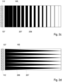
- FIG 2a which shows the mirror layer 105 in a plan view from above - the contact surface then lies parallel to the plane of the page, also in Figure 2b , c , i.e , f , where the sensor layer 104 and the protective body 103 have been omitted for a better understanding - shows the reflective areas 208 are designed as rectangular, more precisely square, their number per unit area, ie per representative area is constant, whereas the area - ie the size - of the reflecting areas 208 with increasing distance from the light source 112, which is designed to radiate light in a linear manner and can be formed, for example, from a large number of LEDs 157 arranged next to one another, is reduced, so that the proportion of the transmitting areas 207 is increased.
- the reflective areas 208 can have any desired geometric shape; they can be designed as polygons, stars, circles, ellipses, rings or also have irregular shapes.
- the proportion of the reflecting areas 208 can decrease linearly--on average over a representative area--or be adapted to a calculated or measured non-linear decrease in the illumination intensity or illuminance for even better compensation of the illumination reduction.
- their number or their distance from one another can also be varied along the distance from the light source 112. This variation can also be linear in a simplified manner or adapted to the actual lighting conditions.
- Reflective areas 208 arranged in a chessboard pattern can, in the case of an arrangement in rows parallel to the line-shaped illumination 112, also be offset in successive rows with respect to the reflective areas of the previous or subsequent row.
- the variation of the distances, the size or the number of areas can also be combined with each other in order to achieve an optimal result.
- FIG. 2b shows a detail of the structure Figure 2a .
- Light source 112 is formed here by individual LEDs that are lined up along the coupling surface parallel to one dimension of the areal extent of sensor layer 104 in order to form a line light source whose length preferably corresponds at least to the corresponding dimension of sensor layer 104.
- the individual LEDs 157 are arranged in such a way that the light bundles emitted by them at an opening angle 152 in a plane parallel to the bearing surface 102 overlap in such a way that when the rays are reflected onto the light-sensitive sensor elements 201, the bundles are always mixed and thus homogenized the illumination of the support surface 102 in the longitudinal direction, ie along the line formed by the light source 112, is ensured.
- the LEDs 157--lasers can also be used here as individual light sources--can advantageously be controlled individually via a controller, in this way irregularities in the illumination can be further reduced.
- the control can be linked to an evaluation of the image content, so that active control of the individual LEDs 157 during the image recording is used to improve the contrasts in the image and to better control the sensor elements 201 .
- Figure 2c shows a further embodiment of a mirror layer on which means for homogenization are formed in strips.
- the transmitting areas 207 are shown as white stripes, the reflective areas 208 as black stripes.
- the transmitting areas 207 and the reflecting areas 208 each extend over the entire extent along the light source 112, ie essentially transversely to the direction of light propagation.
- the change in transmission is also achieved here by changing the size of the areas.
- the width of the black reflecting areas 208 and the white transmitting areas 207, ie the expansion along the light propagation is varied.
- the illuminance can also be homogenized via a linear or adapted reduction in the distances between the reflective areas 208 along the direction of illumination, with the size of the reflective areas 208 then being constant, or else by a combination of size and distance changes.
- Fig. 2d shows a further embodiment of a mirror layer 105 with increasing transmittance with increasing distance from the light source 112, ie along the direction of illumination.
- the change in transmittance is achieved here by enlarging the transmitting areas 207 and correspondingly reducing the reflecting areas 208 transversely to the direction of illumination, i.e. parallel to the line light source, as the distance from the light source 112 increases, and the extent of the reflecting areas 208 in the longitudinal direction of the light source 112 increases with increasing distance from the light source 112.
- the size of the reflecting areas 208 along the direction of illumination is linear here, as can be seen from the straight lines; the dividing lines between transmitting areas 207 and reflecting areas 208 are straight lines, which is easier for production.
- the correction can be improved if the lines have a curve shape that is adapted to the actual course of the decrease in the illuminance, for example.
- Fig. 2f shows a further embodiment of a mirror layer 105, in which the transmission increases with increasing distance from the light source 112.
- the reflective areas 208 here, purely by way of example, have a circular shape that is easy to produce and are all of the same size.
- the circular reflecting areas 208 are arranged here in such a way that their distance in the direction of illumination increases as the distance from the light source 112 increases.
- the circular reflecting areas 208 are each arranged in rows offset to one another, so that a particularly dense arrangement in the area of the light source 112 is possible.
- larger reflective areas 208 and/or larger transmitting areas 207 can be used if the thickness ratios of sensor plane 104 and protective body 103 remain the same, without their projected structure having a quality-reducing effect on the image of an overlying object created in the plane with sensor elements 201.
- FIG. 2e A further embodiment with means for homogenization integrated into the mirror layer is shown Figure 2e , the section shown is perpendicular to the bearing surface 102.
- the thickness of the mirror layer 105 decreases with increasing distance from the light source 112, in this way the degree of transmission of the mirror layer 105 is increased and consequently the degree of reflection is reduced.
- the thickness can decrease linearly with distance or can be specially adapted to a calculated or measured drop in illuminance.
- the mirror layer 105 is wedge-shaped, it can be optically connected to a compensating layer made of a transparent material, which preferably has a similar refractive index to the other materials in order to minimize the splitting of the angular spectrum.
- the outer surfaces of this double wedge structure are then parallel to one another, see above that all other boundary surfaces of the layered collar including the bearing surface are parallel to one another.
- the mirror structures can also be worked out inversely, ie the dark areas that were previously described as reflective are then transparent and vice versa.
- the illumination is from the opposite side, so that the degree of transmission of the mirror layer 105 increases with increasing distance from the light source and the degree of reflection decreases, ie the light source 112 and the coupling surface would then be in the inverse manner to those in Fig. 2a-d , 2f formed mirror layers 105 are arranged on the right side of the mirror layers 105 shown.
- the density of a material which essentially causes the reflection at the mirror layer 105 i.e. a component of the mirror layer 105, can also decrease with increasing distance from the light source.
- the homogenization means is realized by means of a separate layer for this purpose instead of on the mirror layer 105, for example by an absorber 301 with an absorption layer 303, which is arranged between the mirror layer 105 and the sensor layer 104, with increasing distance from the light source 112 the degree of absorption of the illumination light absorption layer 303 decreases and the degree of transmittance increases.
- this is in 12 shown as an example with a wedge-shaped absorption layer 303, to maintain the parallel position of the boundary surfaces, the absorption layer 303 is optically coupled to a transparent compensation layer 304, both together form the absorber 301.
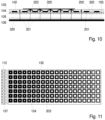
- the device comprises means for homogenizing the amount of light to be detected; these means include a pixel aperture stop layer 124, which may be disposed over the sensor layer 104, with individual pixel aperture stops 132 positioned in 11 are shown greatly enlarged.
- the diaphragm openings 203 of the pixel aperture diaphragms 132 increase with increasing distance from the light source 112, ie the greater the distance from the light source 112, the more light can be detected.
- the means for homogenizing the amount of light to be detected can also include a control for varying the light sensitivity of the sensor elements 201; in this case, the diaphragm openings 203 can also all be identical.
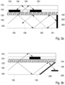
- FIGS. 3a - 3e show different configurations of these suppressants.
- the side of the structure facing away from the light source is shown in each of these figures with the terminal narrow side 300 .
- the portion of the light propagated through the light guide 106 impinges as a light beam 160 at the end on the terminal narrow side 300 of the light guide 106.
- the light - shown here in the form of the light beam 160 by way of example - is reflected and propagated back through the light guide 106, with an angle which is dependent on the inclination of the terminal narrow side 300 in relation to the upper large side 156.
- the back-reflected light beam 161 is totally reflected on the lower large side 155 and continues as a light beam 162 that is reflected again. Since the mirror layer 105 transmits a fraction of the light, a fraction of the returning light beam 163 also passes through the mirror layer 105, the sensor layer 104 and the protective body 103 and impinges on the bearing surface 102. If there is no object lying on it, it will - here it is on the description too 1 referred - totally reflected on the support surface 102 and impinges as a light beam 164 on a light-sensitive sensor element 201; otherwise it enters the overlying object and is scattered there.
- the ray path of the returning light beam is indicated by dashed lines, that of the incoming light beam by solid lines, they correspond to those in connection with 1 described light rays.
- Both the incoming and the returning beams project images of the object texture onto the sensor layer 104 with the individual sensor elements 201, which are shifted here by the distance of two pixels from one another.
- ⁇ z ⁇ d ⁇ tan( ⁇ ) in the direction of the light source 112.
- d is again the thickness of the protective layer
- ⁇ is the angle of the reflected beam to the surface normal of the support surface 102.
- the returning beams are suppressed by the measures described below.
- a simple measure is to provide the closing narrow side 300 with an absorption layer 302, in Figure 3a represented by the thick black bar. This prevents a reflection at the closing narrow side 300 and also prevents radiation from being able to propagate back.
- Another version of the suppression means is in Figure 3b shown.
- the narrow end face 300 is inclined in such a way that the impinging rays preferably impinge at right angles, that is to say the narrow end face 300 is essentially to the propagation direction of light that has entered the light guide 106 along the preferred direction 113 arranged vertically in order to achieve the lowest possible reflection.
- the closing narrow side 300 is provided here with an anti-reflection layer 154 for anti-reflection, in order to minimize the reflection. Transmitted light rays 136 are caught by an additional absorber 305 .
- the narrow terminating side 300 is inclined in relation to the lower large side 155 by an additional angle of inclination 153 to the right angle; the narrow terminating side 300 itself is provided with an absorption layer 302 here.
- the absorption layer 302 can be implemented, for example, by blackening the surfaces, by roughening or by a combination of both or by other measures known in the prior art.
- the terminal narrow side 300 is composed of two or three individual surfaces, which in pairs enclose angles of 0° and 180° with each other, the angles depending on the direction of propagation of the light being predetermined in such a way that the absorption is maximized.
- the lower large side 155 is extended compared to the upper large side 156 and encloses a corresponding angle with the narrow end side 300, which is selected such that reflected light strikes the narrow end side 300 there as perpendicularly as possible.
- the area of the closing narrow side 300 here consists of several absorption surfaces that meet at different angles.
- the portions of the light beams 166 not absorbed by the first absorption layer 302 on the lower large side 155 are directed to the terminal narrow side 300 and the portions of the light beams 167 not absorbed there to the absorption layer 302 formed on the upper large side 156. In this way it is simple technical means possible to achieve a triple absorption, so that a high degree of absorption can be realized.
- the light guide 106 does not end flush with the three other layers of the protective body 103, the sensor layer 104 and the mirror layer 105, but a flush end is easily possible if, for example, the end piece of the upper large side 156 is provided with an absorption layer is, for example, by appropriate roughening before the light guide 106 is optically coupled to the mirror layer 105.
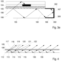
- Light is emitted from light source 112 along preferred direction 113 into light guide 106, with light also being emitted in an angular range around preferred direction 113 for technical reasons 112 are shown.
- Part of the light emitted along the preferred direction 113 is transmitted through the mirror layer 105 and continues there as a central beam 118; the same applies to the edge beams 117 and 119.
- the greater part of the light is reflected and continues as reflected beam 114 .
- the marginal rays are also reflected in the same way, but the diameter of the opening angle area, which can have a cone shape, for example, increases according to the length of the light path, as can be seen, for example, from the marginal rays 120 and 122 .
- homogeneous illumination of the bearing surface 102 is achieved, regardless from a homogenization of illuminance.
- a path for the light to travel through the light guide 106 in front of the first light-sensitive sensor elements 201 should be provided that depends on the thickness of the light guide, the angle of incidence and the angular range of the light emitted by the light source 112 emitted light is adjusted in such a way that the illumination is already homogeneous as far as possible in the area of this first sensor element 201 .
- the angular range of the light beam emitted by the light source 112 determines the resolution of the system with the thickness and the refractive index of the protective body 103 and is preferably less than ⁇ 10° around the preferred direction 113 in the in 4 shown leaf plane, ie in a plane perpendicular to the support surface 102. In the plane parallel to the support surface, however, the widest possible fanning of the light beam is advantageous.
- the protective body 103 can be applied to the sensor layer 104 by means of deposition processes, for example.
- thicker protective bodies 103 can be used; these can also be attached to the sensor layer 104 by means of an adhesive that is adapted in terms of transparency for illumination light and the refractive index are optically coupled, by so-called optical bonding.
- an adhesive layer 140 is between the sensor layer 104 and protective body 103, an adhesive layer 140, which is shown here for clarity with a greater thickness than in reality.
- the use of an adhesive layer 140 results in further technological possibilities for applying protective bodies with greater thicknesses and greater hardness than can be produced in deposition processes, preferably with thicknesses between 50 ⁇ m and 1000 ⁇ m.
- the protective body 103 is then preferably made of hard thin glass, toughened glass or ceramic.
- the protective body must be transparent for the illumination light, but it is also possible to design the protective body itself as a spectral filter, so that it blocks ambient light, for example.
- the protective body 103 can be manufactured separately and processed before being applied to the sensor in order to better adapt it to the intended use.
- the protective body 103 can be hardened, provided with electrically or optically effective coatings, and aesthetic treatments are also conceivable.
- the adhesive used for the adhesive layer 140 is at least partially transparent and can itself or through the introduction of optically active additives have a spectrally limiting effect.
- the refractive index of the adhesive is adapted to that of the protective body 103 .
- the latter measure of spectral filtering limits the wavelength spectrum of the light that can be registered by the sensor elements 201.
- the sensitivity of the sensor element 201 to ambient and stray light can be reduced in this way, and the image quality is increased as a result, particularly if this causes overdriving of some or all sensor elements can be avoided.
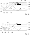
- figure 5 also shows the course of the central ray, taking into account small changes in the refractive index at the interface between the adhesive layer 140 and the protective body 103.
- the central ray 121 strikes the underside of the contact surface 102 and, if there are no skin areas above it, is again totally reflected and emerges as a light ray 142 enters the adhesive layer 140 and then hits the sensor element 201 as a light beam 143.
- FIG 6 A further configuration of the device is shown in FIG 6 , wherein the separate adhesive layer 140 is not shown.
- an additional ambient light shield layer 123 is arranged here between the sensor layer 104 and the protective body 103 , with an ambient light shield 130 being arranged over a sensor element 201 in each case.
- the ambient light screen layer 123 is designed to be transparent. Light rays from ambient light 137 are refracted at receiving surface 102 and propagate as refracted light beams 138 in the direction of the sensor elements 201.
- the ambient light screens 130 can be designed as simple, completely filled absorbing areas. However, the panels can also be used at the same time, as in connection with 11 described, assume the function of homogenization and have transparent areas of different sizes depending on the distance from the light source 112 .
- the absorption of ambient light and the homogenization of the amount of light to be detected can be realized even better if the 11 described diaphragm layer 124 is arranged with pixel aperture diaphragms and the separate ambient light diaphragm layer 123 with ambient light diaphragms 130 for blocking ambient light in the layer system. This is in the Figures 7a and 7b shown.
- Figure 7a shows such a structure with a finger 101 lying on top and diaphragm layers 123 and 124 with pixel aperture diaphragms 132 for homogenizing the quantity of light to be detected in the diaphragm layer 124 and ambient light diaphragms 130 in the ambient light diaphragm layer 123 for selective angle limitation in conjunction with the diaphragm layer 124 arranged underneath, which defines the aperture of the sensor elements 201 controls.
- the homogenization of the amount of light to be detected is only one option; this can also be achieved by a corresponding design of the mirror layer 105, as described above, ie it is also possible for all pixel aperture diaphragms 132 to have the same opening, see above that the conditions for blocking ambient light for all sensor elements 201 are identical.
- Figure 7a shows the course of the beam when the finger 101 is placed on it, with the central beam 118 hitting the contact surface 102 in an area over which there is a papillary valley 110 of the finger 101, so that the central beam 118 is totally reflected and both by the ambient light screen 130 and by the Pixel aperture stop 132 hits the light-sensitive sensor element 201 through the stop opening 203 .
- the situation for ambient light is in Figure 7b additionally shown.
- Light from an external light source 125 enters the finger 101 as a light beam 126, for example, and is scattered there into scattered beams 127 and 128. After multiple scattering, part of the light enters the protective body 103 as a light beam 129 via a papillary strip 111 and the receiving surface 102, the direction of incidence being stochastic.
- the ambient light can take as light beam 129 . Since the light rays 129 of the interfering radiation mainly have angles that are not through the Gap between the absorbing area of the ambient light screen 130 and the pixel aperture screen 132 can propagate, the image recording cannot be disturbed by the interference radiation, the contrast is not reduced.
- the aim of the spectral filter layer 131 is to limit the spectral bandwidth of the light reaching the light-sensitive sensor elements 201 .
- the spectral filter layer 131 can be formed as a uniform surface or structured in such a way that a filter is formed at least over the light-sensitive sensor elements 201 of the sensor layer 104, ie its spectral selectivity can vary over the surface, which is particularly advantageous if Light from an additional light source is used, as described below in connection with 10 is described.
- the spectral filter layer 131 can be applied to the sensor layer 104 before the protective body 103 is applied, for example, or it can be applied to the protective body 103 .
- the spectral filter layer 131 is preferably only permeable for those wavelengths or wavelength ranges that cannot penetrate the object lying thereon. The narrower the transmission band of the spectral filter layer 131, the better the shielding of the structure against stray light.
- FIG. 9a 1 shows a coupling surface 158 inclined at an angle 150 to the surface normal of the mirror layer 105 or to the upper large side 156, the angle 150 preferably has an amount between 10° and 50°.
- the light source 112 is aligned at an appropriate angle, so that preferably at least the central ray 118 strikes the in-coupling surface 158 perpendicularly and the upper large side 156 - assuming an external medium with the refractive index of air instead of the mirror layer 105 - under one for total reflection meets the required angle.
- the angular range in which the light source 112 emits light is symbolized by the marginal rays 117 and 119 drawn in dashed lines. While the central ray 118 strikes the bearing surface 102 at an angle that is sufficient for total internal reflection, the in Figure 9a marginal ray 117 shown is not totally reflected on the support surface 102, but the marginal ray 119 is totally reflected.
- the aperture angle of the light beam propagating in the light guide 106 is effectively limited in this way, even if the light source itself provides a larger aperture angle for the light emission. In the case of light sources that emit light in larger angular ranges, this leads to an improvement in the resolution of the system, but also to losses in intensity.
- Figure 9b shows a to Figure 9a analogous situation where the angle 150 has the same magnitude but a different sign than in Figure 9a and the corresponding beam path for the central beam 118 and the marginal beams 117 and 119.
- the light source 112 emits light in the plane of the page in an angular range 151, i.e. in a plane perpendicular to the bearing surface 102.
- a modification of the Figure 9b shown embodiment shows 9c .
- the coupling surface 158 is provided here with bevels 159 at its edges, which enables the light emitted by the light source 112 to be used more effectively. While the normal of the coupling surface 158 is parallel to the preferred direction 113 or the central ray 118, the bevels 159 enclose an angle that differs from 0° or 180° with the coupling surface 158. The result of this is that the marginal rays 117 and 119 are refracted to a greater extent when they enter the light guide 106 and the effective angular range of the illuminating light is therefore reduced. This leads to an improvement in the resolution of the entire system.
- in-coupling surface 158 can also divide the in-coupling surface 158 into further sub-sections that are tilted relative to one another.
- a division into infinitesimally small surface sections is also possible, for example the coupling-in surface 158 can also have a curvature.
- an additional light source 320 is arranged below the lower large side 155 of the light guide 106 , which emits light in a planar manner and is spaced from the lower large side 155 of the light guide 106 by an air layer 322 .
- the illuminance of the additional light source 320 can be adapted to the transmittance of the means for homogenization and can vary locally. In addition, it can advantageously emit light of at least two wavelength ranges that preferably do not overlap one another.
- One of the multiple wavelength ranges is advantageously adjacent to the wavelength range visible to the human eye, which allows the authenticity of documents to be checked.
- Colored illumination is also advantageous, for which purpose the additional light source 320 is preferably configured to emit light from a red, a blue, and a green wavelength range.
- the wavelength ranges can be switched on.
- the additional light source 320 is used to record objects other than areas of the skin, for example flat documents 325. It is also possible to record objects that do not disturb the total reflection of the light emitted by the light source 112 and therefore do not produce an image on the sensor elements 201 or the sensor layer 104 can produce their texture, it is also used to record objects that produce double images when illuminated with the light source 112 on the sensor layer 104 due to their surface structure.
- the light source 112 is preferably turned off.
- Light beams 321 emitted by the additional light source penetrate the light guide 106, the mirror layer 105, the transmission areas 202 of the sensor layer 104 and the protective body 103 before they also pass through the bearing surface 102.
- the light beams 321 are scattered back as scattered light 323 , which hits the light-sensitive sensor elements 201 .
- the maximum resolution of this imaging process is lower than that of fingerprint imaging using directional illumination through the light guide and depends on the thickness of the protective body. The thicker the protective body, i.e.
- the maximum resolution generally depends on the refractive index of the protective body. The larger this refractive index, the greater the maximum resolution.
- the brightness of the additional light source 320 is expediently matched to the transmission of the corresponding areas of the mirror layer 105, so that uniform illumination is achieved on the bearing surface 102.
- the additional light source advantageously emits white light for the monochrome recording of an object. For checking the authenticity of documents, it is advantageous if the additional light source 320 can also emit light in a further spectrally limited wavelength range by switching, for example in an infrared or ultraviolet range adjacent to the visible wavelength range.
- the additional light source 320 can also emit light sequentially or simultaneously in the restricted wavelength ranges for red, green and blue light. With sequential lighting, an image can be captured in the three colors one after the other and combine them into a color image using appropriate image processing algorithms, as are known in the prior art, if the sensor elements 201 only register the intensity.
- the illumination with the different wavelength ranges can also take place simultaneously, in which case it is necessary for the sensor elements 201 to be designed with corresponding sub-pixels that only detect this wavelength range and/or be designed with different color filters, so that the different sub-pixels each have different Can detect wavelength ranges.
- the additional light source 320 can also be used to display information on the contact surface that shows a user information about the use of the arrangement in the manner of an operating manual or additional information.
- the additional light source 320 must consist of individually controllable elements, e.g. designed as a display.
- the device described above it is possible to record the prints of several fingers at the same time with the same recording quality for all skin areas due to the homogenization, the structure of the device being flat compared to other arrangements based on total reflection for recording autopodia.
- information such as user guidance or an evaluation can be displayed on the support surface, which can also be used as a screen.
- Documents can also be recorded and checked for authenticity using the additional light source, for example with the help of a comparison using connected databases.
Landscapes
- Engineering & Computer Science (AREA)
- Physics & Mathematics (AREA)
- General Physics & Mathematics (AREA)
- Theoretical Computer Science (AREA)
- Multimedia (AREA)
- Optics & Photonics (AREA)
- Human Computer Interaction (AREA)
- Health & Medical Sciences (AREA)
- General Health & Medical Sciences (AREA)
- Vascular Medicine (AREA)
- Manufacturing & Machinery (AREA)
- Image Input (AREA)
- Measurement Of The Respiration, Hearing Ability, Form, And Blood Characteristics Of Living Organisms (AREA)
- Investigating Or Analysing Materials By Optical Means (AREA)
Claims (18)
- Dispositif de saisie par contact simultanée des impressions de plusieurs régions cutanées irriguées d'autopodes humains au moyen d'une réflexion totale perturbée, comprenant, vu depuis la direction d'une région cutanée en contact,- un corps de protection (103) d'une épaisseur prédéterminée avec une surface d'appui (102), la surface d'appui (102) présentant une taille qui permet l'appui simultané de plusieurs autopodes,- une couche de détection (104), comprenant des éléments de détection (201) sensibles à la lumière, disposés en forme de réseau, pour la détection de lumière d'au moins une plage de longueurs d'onde prédéfinie, des zones de transmission (202) étant disposées entre les éléments de détection (201), lesquelles sont transparentes pour la lumière d'au moins une plage de longueurs d'onde d'éclairage prédéfinie,- un guide de lumière (106) en un matériau transparent pour la lumière de la plage de longueurs d'onde d'éclairage prédéfinie, qui est réalisé sous la forme d'une plaque à faces planes et parallèles, avec un grand côté inférieur (155) et un grand côté supérieur (156) disposé parallèlement à celui-ci, qui est tourné vers la couche de détection (104), ainsi que plusieurs petits côtés reliant les grands côtés (155, 156), l'un des petits côtés étant réalisé comme surface de couplage (158) pour la lumière d'éclairage, et- une source de lumière (112) émettant une lumière d'éclairage le long d'une direction longitudinale de la surface de couplage (158), caractérisé en ce que- la source de lumière (112) est réalisée de manière à émettre de la lumière dans une plage angulaire limitée (151) autour d'une direction préférentielle (113), la direction préférentielle (113) incluant avec les grands côtés (155, 156) un angle d'incidence qui est prédéterminé de telle sorte que la lumière qui est émise dans la plage angulaire (151) serait, après entrée dans le guide de lumière (106), réfléchie de manière prépondérante totalement sur les grands côtés (155, 156) dans le cas d'un milieu s'y appliquant avec un indice de réfraction de l'air,- entre la couche de détection (104) et le guide de lumière (106) est disposée une couche de miroir (105) qui réfléchit une partie de la lumière d'éclairage en retour dans le guide de lumière (106) et transmet une autre partie de la lumière d'éclairage, et en ce que- le dispositif comprend des moyens pour homogénéiser l'intensité d'éclairage de la lumière d'éclairage qui sort du guide de lumière (106) par le grand côté supérieur (156) de celui-ci et arrive sur la surface d'appui (102), et/ou des moyens pour homogénéiser une quantité de lumière à détecter en fonction de l'intensité d'éclairage de la lumière d'éclairage qui arrive sur la surface d'appui (102) à partir du corps de protection (103), respectivement en fonction de la distance à la source de lumière (112),- toutes les couches étant couplées optiquement selon leur ordre d'empilement, respectivement par une liaison directe ou par une couche adhésive.
- Dispositif selon la revendication 1, caractérisé en ce que les moyens d'homogénéisation de l'intensité d'éclairage sont formés sur la couche de miroir (105) qui est couplée optiquement à la couche de détection (104) et au guide de lumière (106), le degré de réflexion de la couche de miroir (105) diminuant et le degré de transmission augmentant avec l'éloignement de la source de lumière (112).
- Dispositif selon la revendication 2, caractérisé en ce que la couche de miroir (105) comprend des zones réfléchissantes (208) et des zones transmissives (207), la proportion des zones réfléchissantes (208) par unité de surface diminuant en moyenne avec la distance à la source de lumière (112) et la proportion des zones transmissives (207) par unité de surface augmentant en moyenne avec la distance à la source de lumière (112).
- Dispositif selon la revendication 3, caractérisé en ce que la densité et/ou la taille des zones réfléchissantes (208) diminue avec l'éloignement de la source de lumière (112), tandis que la densité et/ou la taille des zones de transmission (207) augmente.
- Dispositif selon la revendication 2, caractérisé en ce que l'épaisseur de la couche de miroir (105) diminue avec l'éloignement de la source de lumière (112).
- Dispositif selon la revendication 1, caractérisé en ce que les moyens d'homogénéisation de l'intensité d'éclairage comprennent une couche absorbante (303) qui est disposée entre la couche réfléchissante (105) et la couche de détection (104) ou entre les éléments de détection (201) dans les zones de transmission (204), le degré d'absorption de la couche absorbante pour la lumière d'intensité d'éclairage diminuant et le degré de transmission augmentant avec l'éloignement de la source de lumière (112).
- Dispositif selon l'une quelconque des revendications 1 à 6, caractérisé en ce que les moyens d'homogénéisation de la quantité de lumière à détecter comprennent des diaphragmes d'ouverture de pixels (132) disposés au-dessus des éléments de détection (201) et dont les ouvertures (203) augmentent avec l'éloignement de la source de lumière (112).
- Dispositif selon l'une quelconque des revendications 1 à 7, caractérisé en ce que les moyens d'homogénéisation de la quantité de lumière à détecter comprennent une commande pour faire varier la sensibilité des éléments de détection (201).
- Dispositif selon l'une quelconque des revendications 1 à 8, caractérisé en ce que la normale de la surface de couplage (158) est parallèle à la direction préférentielle (113).
- Dispositif selon l'une quelconque des revendications 1 à 9, caractérisé en ce que des moyens de suppression de la formation de rayons de retour sont formés sur un petit côté du guide de lumière (106) réalisé sous forme de petit côté de terminaison (300), qui est opposé à la surface de couplage (158) dans la direction de propagation de la lumière.
- Dispositif selon la revendication 10, caractérisé en ce que le petit côté de terminaison (300) est pourvu d'une couche d'absorption (302) et/ou est disposé sensiblement perpendiculairement à la direction de propagation de la lumière entrée dans le guide de lumière (106) le long de la direction préférentielle (113).
- Dispositif selon l'une quelconque des revendications 1 à 11, caractérisé en ce que le corps de protection (103) est réalisé avec une épaisseur comprise entre 50 µm et 1000 µm et est couplé optiquement à la couche de détection.
- Dispositif selon l'une quelconque des revendications 1 à 12, caractérisé en ce qu'une couche de diaphragme (124) est disposée entre la surface d'appui (102) et la couche de détection (104) pour supprimer la détection de la lumière ambiante, un diaphragme d'ouverture de pixels (132) étant respectivement disposé au-dessus d'un élément de détection (201), et/ou une couche de filtre spectral (131) étant disposée entre la couche de détection (104) et le corps de protection (103), et/ou le corps de protection (103) étant conçu comme une couche de filtre spectral (131).
- Dispositif selon l'une quelconque des revendications 1 à 13, caractérisé en ce qu'une source de lumière supplémentaire (320) émettant de la lumière sous forme de surface est disposée en dessous du grand côté inférieur (155) du guide de lumière (106), laquelle est espacée du grand côté inférieur (155) du guide de lumière (106) par une couche d'air (322).
- Dispositif selon la revendication 14, caractérisé en ce que l'intensité d'éclairage de la source de lumière supplémentaire (320) est adapté au degré de transmission des moyens d'homogénéisation.
- Dispositif selon la revendication 14 ou 15, caractérisé en ce que la source de lumière supplémentaire (320) est conçue pour émettre de la lumière à partir d'au moins deux plages de longueurs d'onde qui ne se chevauchent pas.
- Dispositif selon la revendication 16, caractérisé en ce que l'une desdites au moins deux plages de longueurs d'onde est adjacente à la plage de longueurs d'onde visible par l'oeil humain.
- Dispositif selon la revendication 16 ou 17, caractérisé en ce que la source de lumière supplémentaire (322) est conçue pour émettre de la lumière à partir d'une plage de longueurs d'onde rouge, bleue et verte, et la lumière de ces plages de longueurs d'onde peut être activée et désactivée individuellement au moyen d'une commande.
Applications Claiming Priority (1)
| Application Number | Priority Date | Filing Date | Title |
|---|---|---|---|
| DE102017119983.7A DE102017119983B3 (de) | 2017-08-31 | 2017-08-31 | Vorrichtung zur kontaktbasierten gleichzeitigen Aufnahme von Abdrücken von Autopodien |
Publications (3)
| Publication Number | Publication Date |
|---|---|
| EP3460455A2 EP3460455A2 (fr) | 2019-03-27 |
| EP3460455A3 EP3460455A3 (fr) | 2019-07-03 |
| EP3460455B1 true EP3460455B1 (fr) | 2024-02-21 |
Family
ID=62985883
Family Applications (1)
| Application Number | Title | Priority Date | Filing Date |
|---|---|---|---|
| EP18181754.5A Active EP3460455B1 (fr) | 2017-08-31 | 2018-07-04 | Dispositif de saisie par contact simultanée des impressions des autopodes |
Country Status (4)
| Country | Link |
|---|---|
| US (1) | US10366273B2 (fr) |
| EP (1) | EP3460455B1 (fr) |
| CN (1) | CN109426812B (fr) |
| DE (1) | DE102017119983B3 (fr) |
Families Citing this family (12)
| Publication number | Priority date | Publication date | Assignee | Title |
|---|---|---|---|---|
| TWI630502B (zh) * | 2016-08-05 | 2018-07-21 | 金佶科技股份有限公司 | 取像裝置 |
| US10726240B2 (en) * | 2015-07-09 | 2020-07-28 | Gingy Technology Inc. | Image capturing apparatus |
| US10796128B2 (en) * | 2017-12-12 | 2020-10-06 | Fingerprint Cards Ab | Optical sensor with ambient light filter |
| KR102485577B1 (ko) * | 2018-01-08 | 2023-01-09 | 삼성디스플레이 주식회사 | 백라이트 유닛 및 이를 포함하는 표시 장치 |
| CN111819575A (zh) * | 2018-03-15 | 2020-10-23 | 指纹卡有限公司 | 生物计量成像装置和用于制造生物计量成像装置的方法 |
| TWI684028B (zh) * | 2018-03-28 | 2020-02-01 | 世界先進積體電路股份有限公司 | 半導體裝置及其形成方法 |
| DE102018122896A1 (de) | 2018-09-18 | 2020-03-19 | JENETRIC GmbH | Verfahren und Vorrichtung zur Kontrolle eines mobilen Eingabegeräts |
| KR20200137079A (ko) | 2019-05-28 | 2020-12-09 | 삼성디스플레이 주식회사 | 지문 센서 및 이를 포함하는 표시 장치 |
| CN110119046B (zh) * | 2019-05-31 | 2022-01-14 | 厦门天马微电子有限公司 | 一种显示面板和显示装置 |
| DE102019126408B4 (de) | 2019-09-30 | 2021-12-16 | JENETRIC GmbH | Vorrichtung und Verfahren zur Darstellung von Informationen und zur kontaktbasierten gleichzeitigen Aufnahme von Hautabdrücken mehrerer durchbluteter Hautbereiche menschlicher Autopodien |
| CN113310029A (zh) * | 2021-05-26 | 2021-08-27 | 一汽奔腾轿车有限公司 | 一种星空花纹后位置灯 |
| CN114001325B (zh) * | 2021-10-21 | 2023-09-26 | 东风柳州汽车有限公司 | 一种星空顶结构 |
Family Cites Families (27)
| Publication number | Priority date | Publication date | Assignee | Title |
|---|---|---|---|---|
| GB2196100B (en) * | 1986-10-01 | 1990-07-04 | Mitsubishi Rayon Co | Light diffusing device |
| JP2000172833A (ja) | 1998-12-10 | 2000-06-23 | Omron Corp | 指紋照合装置 |
| WO2001036905A1 (fr) | 1999-11-18 | 2001-05-25 | Asahi Glass Company, Limited | Lecteur d'empreintes digitales |
| JP2001312916A (ja) * | 2000-02-24 | 2001-11-09 | Sony Corp | 面光源装置 |
| WO2002025167A1 (fr) * | 2000-09-25 | 2002-03-28 | Mitsubishi Rayon Co., Ltd. | Dispositif d'eclairage |
| JP2002372605A (ja) * | 2001-06-15 | 2002-12-26 | Fuji Photo Film Co Ltd | 光学素子及びこれを用いた表示体 |
| JP4154874B2 (ja) * | 2001-07-30 | 2008-09-24 | カシオ計算機株式会社 | 指紋読取装置および指紋読取方法 |
| JP2003281920A (ja) * | 2002-03-22 | 2003-10-03 | Casio Comput Co Ltd | 照明装置 |
| RU2412460C2 (ru) | 2006-04-10 | 2011-02-20 | Электролюкс Хоум Продактс Корпорейшн Н.В. | Бытовой электроприбор, оснащенный датчиком идентификации "отпечатка пальца" |
| WO2008033265A2 (fr) | 2006-09-11 | 2008-03-20 | Validity Sensors, Inc. | Procédé et dispositif permettant de suivre le déplacement d'une empreinte digitale au moyen d'une barrette en ligne |
| JP4640415B2 (ja) * | 2008-01-18 | 2011-03-02 | ソニー株式会社 | 生体認証装置 |
| US8730212B2 (en) * | 2009-08-21 | 2014-05-20 | Microsoft Corporation | Illuminator for touch- and object-sensitive display |
| WO2011059496A1 (fr) | 2009-11-11 | 2011-05-19 | Cross Match Technologies, Inc. | Appareil et procédé de détermination du séquencement de doigts dans des images pour un balayage à deux doigts d'images d'empreintes digitales |
| JP5609361B2 (ja) * | 2010-07-21 | 2014-10-22 | 富士ゼロックス株式会社 | 導光体及び画像読取装置 |
| US8531773B2 (en) * | 2011-01-10 | 2013-09-10 | Microvision, Inc. | Substrate guided relay having a homogenizing layer |
| JP5720290B2 (ja) * | 2011-02-16 | 2015-05-20 | セイコーエプソン株式会社 | 虚像表示装置 |
| US20120321149A1 (en) | 2011-05-17 | 2012-12-20 | Carver John F | Fingerprint sensors |
| US9019240B2 (en) * | 2011-09-29 | 2015-04-28 | Qualcomm Mems Technologies, Inc. | Optical touch device with pixilated light-turning features |
| US10024655B2 (en) * | 2011-11-11 | 2018-07-17 | Cross Match Technologies, Inc. | Ambient light rejection for non-imaging contact sensors |
| US9285623B2 (en) * | 2012-10-04 | 2016-03-15 | Corning Incorporated | Touch screen systems with interface layer |
| CN103942559A (zh) * | 2013-01-21 | 2014-07-23 | 义明科技股份有限公司 | 影像感测装置以及影像感测装置的解码电路 |
| DE102014227028A1 (de) * | 2014-12-30 | 2016-06-30 | Magneti Marelli GmbH | Anzeigeinstrument zur Anzeige eines Betriebszustands eines Kraftfahrzeugs |
| US10147757B2 (en) * | 2015-02-02 | 2018-12-04 | Synaptics Incorporated | Image sensor structures for fingerprint sensing |
| DE102015115381A1 (de) * | 2015-09-11 | 2017-03-16 | JENETRIC GmbH | Vorrichtung und Verfahren zur optischen Aufnahme von Abdrücken von durchbluteten Hautbereichen |
| DE102015116026A1 (de) | 2015-09-22 | 2017-03-23 | JENETRIC GmbH | Vorrichtung und Verfahren zur direkten optischen Bildaufnahme von Dokumenten und / oder lebenden Hautbereichen ohne abbildende optische Elemente |
| EP3405834B1 (fr) * | 2016-01-22 | 2020-10-07 | LG Electronics Inc. -1- | Dispositif d'affichage |
| CN108021845A (zh) * | 2016-10-31 | 2018-05-11 | 上海箩箕技术有限公司 | 光学指纹传感器模组 |
-
2017
- 2017-08-31 DE DE102017119983.7A patent/DE102017119983B3/de active Active
-
2018
- 2018-07-04 EP EP18181754.5A patent/EP3460455B1/fr active Active
- 2018-08-29 CN CN201810999603.5A patent/CN109426812B/zh active Active
- 2018-08-30 US US16/117,061 patent/US10366273B2/en active Active
Also Published As
| Publication number | Publication date |
|---|---|
| DE102017119983B3 (de) | 2018-09-27 |
| US10366273B2 (en) | 2019-07-30 |
| EP3460455A2 (fr) | 2019-03-27 |
| US20190065816A1 (en) | 2019-02-28 |
| CN109426812A (zh) | 2019-03-05 |
| CN109426812B (zh) | 2020-05-05 |
| EP3460455A3 (fr) | 2019-07-03 |
Similar Documents
| Publication | Publication Date | Title |
|---|---|---|
| EP3460455B1 (fr) | Dispositif de saisie par contact simultanée des impressions des autopodes | |
| DE102015115484B3 (de) | Vorrichtung und Verfahren zur optischen Direktaufnahme von lebenden Hautbereichen | |
| EP3147823B1 (fr) | Dispositif et procede d'enregistrement d'images optique direct de documents et/ou de zones cutanees vivantes sans elements optiques de representation | |
| DE102018122918B4 (de) | Vorrichtung zur optischen Direktaufnahme von Hautabdrücken für mobile Anwendung | |
| DE60023156T2 (de) | Verfahren und gerät zur verminderung der trapezverzerrung und verbesserung der bildschärfe in einem optischen bilderfassungssystem | |
| EP3142043B1 (fr) | Dispositif et procede de reception optique d'empreintes de zones de peau irriguees | |
| EP3120535B1 (fr) | Dispositif et procede de mesure optique d'un document et procédé pour la fabrication d'un tel dispositif | |
| DE4421243A1 (de) | Einrichtung zur Eingabe eines Fingerabdrucks | |
| WO2019144997A1 (fr) | Dispositif d'enregistrement optique direct d'empreintes cutanées et de documents | |
| DE102018122872B4 (de) | Display mit integriertem Matrixsensor und Verfahren zur optischen Aufnahme der Papillarstruktur wenigstens eines Fingers mit dem Display | |
| EP3531012B9 (fr) | Dispositif d'éclairage pour véhicules automobiles pourvu de guide de lumière allongé | |
| DE102019126408B4 (de) | Vorrichtung und Verfahren zur Darstellung von Informationen und zur kontaktbasierten gleichzeitigen Aufnahme von Hautabdrücken mehrerer durchbluteter Hautbereiche menschlicher Autopodien | |
| EP1782393A2 (fr) | Dispositif pour examiner des documents | |
| EP3084397B1 (fr) | Spectromètre infrarouge atr | |
| EP3627390B1 (fr) | Dispositif de prise optique directe d'empreintes | |
| DE1816677A1 (de) | Faseroptikelement | |
| DE2727927A1 (de) | Vorrichtung zur unterscheidung bestimmter winkelbereiche bei von einer oberflaeche ausgehendem licht | |
| EP1064573B1 (fr) | Spectrometre a couche mince avec reseau de transmission | |
| DE2846190A1 (de) | Vorrichtung zum verarbeiten einer fingerabdruck betreffenden information | |
| DE112019002482T5 (de) | Decken-ausleuchtungs-fenster | |
| DE69805792T2 (de) | Optische Architektur für infrarotes Betrachtungssystem | |
| EP3474529B1 (fr) | Éclairage pour la saisie de documents optique | |
| WO2022042957A1 (fr) | Dispositif pour capturer des impressions d'autopodes et utilisation associée | |
| WO2021144171A1 (fr) | Dispositif d'identification biométrique à l'aide d'empreintes digitales et/ou de caractéristiques de main, et procédé d'identification biométrique à l'aide desdites caractéristiques | |
| WO2019228931A2 (fr) | Capteur optique d'empreintes digitales |
Legal Events
| Date | Code | Title | Description |
|---|---|---|---|
| PUAI | Public reference made under article 153(3) epc to a published international application that has entered the european phase |
Free format text: ORIGINAL CODE: 0009012 |
|
| STAA | Information on the status of an ep patent application or granted ep patent |
Free format text: STATUS: THE APPLICATION HAS BEEN PUBLISHED |
|
| AK | Designated contracting states |
Kind code of ref document: A2 Designated state(s): AL AT BE BG CH CY CZ DE DK EE ES FI FR GB GR HR HU IE IS IT LI LT LU LV MC MK MT NL NO PL PT RO RS SE SI SK SM TR |
|
| AX | Request for extension of the european patent |
Extension state: BA ME |
|
| RAP1 | Party data changed (applicant data changed or rights of an application transferred) |
Owner name: JENETRIC GMBH |
|
| PUAL | Search report despatched |
Free format text: ORIGINAL CODE: 0009013 |
|
| AK | Designated contracting states |
Kind code of ref document: A3 Designated state(s): AL AT BE BG CH CY CZ DE DK EE ES FI FR GB GR HR HU IE IS IT LI LT LU LV MC MK MT NL NO PL PT RO RS SE SI SK SM TR |
|
| AX | Request for extension of the european patent |
Extension state: BA ME |
|
| RIC1 | Information provided on ipc code assigned before grant |
Ipc: F21V 8/00 20060101ALI20190529BHEP Ipc: G01N 21/552 20140101AFI20190529BHEP Ipc: G06K 9/00 20060101ALI20190529BHEP Ipc: G06K 9/20 20060101ALI20190529BHEP |
|
| RIN1 | Information on inventor provided before grant (corrected) |
Inventor name: MORGENEIER, DIRK Inventor name: HILLMANN, JUERGEN Inventor name: RIEHL, PHILIPP Inventor name: KRENZER, DANIEL Inventor name: RICHTER, UNDINE Inventor name: REINHOLD, JOERG |
|
| STAA | Information on the status of an ep patent application or granted ep patent |
Free format text: STATUS: REQUEST FOR EXAMINATION WAS MADE |
|
| 17P | Request for examination filed |
Effective date: 20191220 |
|
| RBV | Designated contracting states (corrected) |
Designated state(s): AL AT BE BG CH CY CZ DE DK EE ES FI FR GB GR HR HU IE IS IT LI LT LU LV MC MK MT NL NO PL PT RO RS SE SI SK SM TR |
|
| STAA | Information on the status of an ep patent application or granted ep patent |
Free format text: STATUS: EXAMINATION IS IN PROGRESS |
|
| 17Q | First examination report despatched |
Effective date: 20210430 |
|
| STAA | Information on the status of an ep patent application or granted ep patent |
Free format text: STATUS: EXAMINATION IS IN PROGRESS |
|
| RAP3 | Party data changed (applicant data changed or rights of an application transferred) |
Owner name: JENETRIC GMBH |
|
| REG | Reference to a national code |
Ref document number: 502018013106 Country of ref document: DE Ref country code: DE Ref legal event code: R079 Free format text: PREVIOUS MAIN CLASS: G01N0021552000 Ipc: G06V0010141000 |
|
| GRAP | Despatch of communication of intention to grant a patent |
Free format text: ORIGINAL CODE: EPIDOSNIGR1 |
|
| STAA | Information on the status of an ep patent application or granted ep patent |
Free format text: STATUS: GRANT OF PATENT IS INTENDED |
|
| RIC1 | Information provided on ipc code assigned before grant |
Ipc: F21V 8/00 20060101ALI20230131BHEP Ipc: G06V 40/13 20220101ALI20230131BHEP Ipc: G06V 10/147 20220101ALI20230131BHEP Ipc: G06V 10/141 20220101AFI20230131BHEP |
|
| INTG | Intention to grant announced |
Effective date: 20230216 |
|
| GRAS | Grant fee paid |
Free format text: ORIGINAL CODE: EPIDOSNIGR3 |
|
| P01 | Opt-out of the competence of the unified patent court (upc) registered |
Effective date: 20230606 |
|
| GRAA | (expected) grant |
Free format text: ORIGINAL CODE: 0009210 |
|
| STAA | Information on the status of an ep patent application or granted ep patent |
Free format text: STATUS: THE PATENT HAS BEEN GRANTED |
|
| AK | Designated contracting states |
Kind code of ref document: B1 Designated state(s): AL AT BE BG CH CY CZ DE DK EE ES FI FR GB GR HR HU IE IS IT LI LT LU LV MC MK MT NL NO PL PT RO RS SE SI SK SM TR |
|
| REG | Reference to a national code |
Ref country code: GB Ref legal event code: FG4D Free format text: NOT ENGLISH |
|
| REG | Reference to a national code |
Ref country code: CH Ref legal event code: EP |
|
| REG | Reference to a national code |
Ref country code: DE Ref legal event code: R096 Ref document number: 502018013106 Country of ref document: DE |
|
| REG | Reference to a national code |
Ref country code: IE Ref legal event code: FG4D Free format text: LANGUAGE OF EP DOCUMENT: GERMAN |
|
| PUAC | Information related to the publication of a b1 document modified or deleted |
Free format text: ORIGINAL CODE: 0009299EPPU |
|
| STAA | Information on the status of an ep patent application or granted ep patent |
Free format text: STATUS: GRANT OF PATENT IS INTENDED |
|
| REG | Reference to a national code |
Ref country code: CH Ref legal event code: PK Free format text: DIE ERTEILUNG WURDE VOM EPA WIDERRUFEN. |
|
| 19U | Interruption of proceedings before grant |
Effective date: 20230601 |
|
| 19W | Proceedings resumed before grant after interruption of proceedings |
Effective date: 20240102 |
|
| DB1 | Publication of patent cancelled |
Effective date: 20230929 |
|
| RAP3 | Party data changed (applicant data changed or rights of an application transferred) |
Owner name: DERMALOG JENETRIC GMBH |
|
| REG | Reference to a national code |
Ref country code: DE Ref legal event code: R107 Ref document number: 502018013106 Country of ref document: DE |
|
| REG | Reference to a national code |
Ref country code: AT Ref legal event code: REZ Ref document number: 1606418 Country of ref document: AT Kind code of ref document: T Effective date: 20230830 |
|
| REG | Reference to a national code |
Ref country code: LT Ref legal event code: MG9D |
|
| GRAA | (expected) grant |
Free format text: ORIGINAL CODE: 0009210 |
|
| STAA | Information on the status of an ep patent application or granted ep patent |
Free format text: STATUS: THE PATENT HAS BEEN GRANTED |
|
| RAP3 | Party data changed (applicant data changed or rights of an application transferred) |
Owner name: DERMALOG JENETRIC GMBH |
|
| AK | Designated contracting states |
Kind code of ref document: B1 Designated state(s): AL AT BE BG CH CY CZ DE DK EE ES FI FR GB GR HR HU IE IS IT LI LT LU LV MC MK MT NL NO PL PT RO RS SE SI SK SM TR |
|
| REG | Reference to a national code |
Ref country code: GB Ref legal event code: FG4D Free format text: NOT ENGLISH |
|
| REG | Reference to a national code |
Ref country code: CH Ref legal event code: EP |
|
| REG | Reference to a national code |
Ref country code: DE Ref legal event code: R096 Ref document number: 502018013106 Country of ref document: DE |
|
| REG | Reference to a national code |
Ref country code: DE Ref legal event code: R081 Ref document number: 502018013106 Country of ref document: DE Owner name: DERMALOG JENETRIC GMBH, DE Free format text: FORMER OWNER: JENETRIC GMBH, 07749 JENA, DE |
|
| REG | Reference to a national code |
Ref country code: LT Ref legal event code: MG9D |
|
| REG | Reference to a national code |
Ref country code: NL Ref legal event code: MP Effective date: 20240221 |
|
| PG25 | Lapsed in a contracting state [announced via postgrant information from national office to epo] |
Ref country code: LT Free format text: LAPSE BECAUSE OF FAILURE TO SUBMIT A TRANSLATION OF THE DESCRIPTION OR TO PAY THE FEE WITHIN THE PRESCRIBED TIME-LIMIT Effective date: 20240221 |
|
| PG25 | Lapsed in a contracting state [announced via postgrant information from national office to epo] |
Ref country code: RS Free format text: LAPSE BECAUSE OF FAILURE TO SUBMIT A TRANSLATION OF THE DESCRIPTION OR TO PAY THE FEE WITHIN THE PRESCRIBED TIME-LIMIT Effective date: 20240521 Ref country code: HR Free format text: LAPSE BECAUSE OF FAILURE TO SUBMIT A TRANSLATION OF THE DESCRIPTION OR TO PAY THE FEE WITHIN THE PRESCRIBED TIME-LIMIT Effective date: 20240221 Ref country code: NL Free format text: LAPSE BECAUSE OF FAILURE TO SUBMIT A TRANSLATION OF THE DESCRIPTION OR TO PAY THE FEE WITHIN THE PRESCRIBED TIME-LIMIT Effective date: 20240221 |
|
| PG25 | Lapsed in a contracting state [announced via postgrant information from national office to epo] |
Ref country code: ES Free format text: LAPSE BECAUSE OF FAILURE TO SUBMIT A TRANSLATION OF THE DESCRIPTION OR TO PAY THE FEE WITHIN THE PRESCRIBED TIME-LIMIT Effective date: 20240221 |
|
| PG25 | Lapsed in a contracting state [announced via postgrant information from national office to epo] |
Ref country code: RS Free format text: LAPSE BECAUSE OF FAILURE TO SUBMIT A TRANSLATION OF THE DESCRIPTION OR TO PAY THE FEE WITHIN THE PRESCRIBED TIME-LIMIT Effective date: 20240521 Ref country code: NO Free format text: LAPSE BECAUSE OF FAILURE TO SUBMIT A TRANSLATION OF THE DESCRIPTION OR TO PAY THE FEE WITHIN THE PRESCRIBED TIME-LIMIT Effective date: 20240521 Ref country code: NL Free format text: LAPSE BECAUSE OF FAILURE TO SUBMIT A TRANSLATION OF THE DESCRIPTION OR TO PAY THE FEE WITHIN THE PRESCRIBED TIME-LIMIT Effective date: 20240221 Ref country code: LT Free format text: LAPSE BECAUSE OF FAILURE TO SUBMIT A TRANSLATION OF THE DESCRIPTION OR TO PAY THE FEE WITHIN THE PRESCRIBED TIME-LIMIT Effective date: 20240221 Ref country code: HR Free format text: LAPSE BECAUSE OF FAILURE TO SUBMIT A TRANSLATION OF THE DESCRIPTION OR TO PAY THE FEE WITHIN THE PRESCRIBED TIME-LIMIT Effective date: 20240221 Ref country code: ES Free format text: LAPSE BECAUSE OF FAILURE TO SUBMIT A TRANSLATION OF THE DESCRIPTION OR TO PAY THE FEE WITHIN THE PRESCRIBED TIME-LIMIT Effective date: 20240221 Ref country code: BG Free format text: LAPSE BECAUSE OF FAILURE TO SUBMIT A TRANSLATION OF THE DESCRIPTION OR TO PAY THE FEE WITHIN THE PRESCRIBED TIME-LIMIT Effective date: 20240221 |
|
| PG25 | Lapsed in a contracting state [announced via postgrant information from national office to epo] |
Ref country code: PT Free format text: LAPSE BECAUSE OF FAILURE TO SUBMIT A TRANSLATION OF THE DESCRIPTION OR TO PAY THE FEE WITHIN THE PRESCRIBED TIME-LIMIT Effective date: 20240621 Ref country code: PL Free format text: LAPSE BECAUSE OF FAILURE TO SUBMIT A TRANSLATION OF THE DESCRIPTION OR TO PAY THE FEE WITHIN THE PRESCRIBED TIME-LIMIT Effective date: 20240221 |
|
| PG25 | Lapsed in a contracting state [announced via postgrant information from national office to epo] |
Ref country code: PT Free format text: LAPSE BECAUSE OF FAILURE TO SUBMIT A TRANSLATION OF THE DESCRIPTION OR TO PAY THE FEE WITHIN THE PRESCRIBED TIME-LIMIT Effective date: 20240621 Ref country code: PL Free format text: LAPSE BECAUSE OF FAILURE TO SUBMIT A TRANSLATION OF THE DESCRIPTION OR TO PAY THE FEE WITHIN THE PRESCRIBED TIME-LIMIT Effective date: 20240221 Ref country code: LV Free format text: LAPSE BECAUSE OF FAILURE TO SUBMIT A TRANSLATION OF THE DESCRIPTION OR TO PAY THE FEE WITHIN THE PRESCRIBED TIME-LIMIT Effective date: 20240221 |
|
| PGFP | Annual fee paid to national office [announced via postgrant information from national office to epo] |
Ref country code: DE Payment date: 20240719 Year of fee payment: 7 |
|
| PG25 | Lapsed in a contracting state [announced via postgrant information from national office to epo] |
Ref country code: DK Free format text: LAPSE BECAUSE OF FAILURE TO SUBMIT A TRANSLATION OF THE DESCRIPTION OR TO PAY THE FEE WITHIN THE PRESCRIBED TIME-LIMIT Effective date: 20240221 |
|
| PG25 | Lapsed in a contracting state [announced via postgrant information from national office to epo] |
Ref country code: SM Free format text: LAPSE BECAUSE OF FAILURE TO SUBMIT A TRANSLATION OF THE DESCRIPTION OR TO PAY THE FEE WITHIN THE PRESCRIBED TIME-LIMIT Effective date: 20240221 |
|
| PGFP | Annual fee paid to national office [announced via postgrant information from national office to epo] |
Ref country code: FR Payment date: 20240730 Year of fee payment: 7 |
|
| PG25 | Lapsed in a contracting state [announced via postgrant information from national office to epo] |
Ref country code: CZ Free format text: LAPSE BECAUSE OF FAILURE TO SUBMIT A TRANSLATION OF THE DESCRIPTION OR TO PAY THE FEE WITHIN THE PRESCRIBED TIME-LIMIT Effective date: 20240221 Ref country code: EE Free format text: LAPSE BECAUSE OF FAILURE TO SUBMIT A TRANSLATION OF THE DESCRIPTION OR TO PAY THE FEE WITHIN THE PRESCRIBED TIME-LIMIT Effective date: 20240221 |
|
| PG25 | Lapsed in a contracting state [announced via postgrant information from national office to epo] |
Ref country code: SK Free format text: LAPSE BECAUSE OF FAILURE TO SUBMIT A TRANSLATION OF THE DESCRIPTION OR TO PAY THE FEE WITHIN THE PRESCRIBED TIME-LIMIT Effective date: 20240221 |