EP3459900A1 - Support en arc pourvu de pièce rabattable - Google Patents
Support en arc pourvu de pièce rabattable Download PDFInfo
- Publication number
- EP3459900A1 EP3459900A1 EP18196441.2A EP18196441A EP3459900A1 EP 3459900 A1 EP3459900 A1 EP 3459900A1 EP 18196441 A EP18196441 A EP 18196441A EP 3459900 A1 EP3459900 A1 EP 3459900A1
- Authority
- EP
- European Patent Office
- Prior art keywords
- vehicle
- folding
- carrier
- folding part
- transport
- Prior art date
- Legal status (The legal status is an assumption and is not a legal conclusion. Google has not performed a legal analysis and makes no representation as to the accuracy of the status listed.)
- Granted
Links
- 239000000969 carrier Substances 0.000 claims abstract description 9
- 230000032258 transport Effects 0.000 description 44
- 210000001331 nose Anatomy 0.000 description 10
- 238000009434 installation Methods 0.000 description 6
- 210000001503 joint Anatomy 0.000 description 6
- 235000004522 Pentaglottis sempervirens Nutrition 0.000 description 4
- 230000007246 mechanism Effects 0.000 description 3
- 230000008901 benefit Effects 0.000 description 2
- 238000010276 construction Methods 0.000 description 2
- 230000001419 dependent effect Effects 0.000 description 2
- 206010010219 Compulsions Diseases 0.000 description 1
- 239000006071 cream Substances 0.000 description 1
- 230000006735 deficit Effects 0.000 description 1
- 238000005259 measurement Methods 0.000 description 1
- 238000012986 modification Methods 0.000 description 1
- 230000004048 modification Effects 0.000 description 1
- 230000007480 spreading Effects 0.000 description 1
Images


Classifications
-
- B—PERFORMING OPERATIONS; TRANSPORTING
- B66—HOISTING; LIFTING; HAULING
- B66C—CRANES; LOAD-ENGAGING ELEMENTS OR DEVICES FOR CRANES, CAPSTANS, WINCHES, OR TACKLES
- B66C23/00—Cranes comprising essentially a beam, boom, or triangular structure acting as a cantilever and mounted for translatory of swinging movements in vertical or horizontal planes or a combination of such movements, e.g. jib-cranes, derricks, tower cranes
- B66C23/62—Constructional features or details
- B66C23/72—Counterweights or supports for balancing lifting couples
- B66C23/78—Supports, e.g. outriggers, for mobile cranes
- B66C23/80—Supports, e.g. outriggers, for mobile cranes hydraulically actuated
-
- B—PERFORMING OPERATIONS; TRANSPORTING
- B60—VEHICLES IN GENERAL
- B60S—SERVICING, CLEANING, REPAIRING, SUPPORTING, LIFTING, OR MANOEUVRING OF VEHICLES, NOT OTHERWISE PROVIDED FOR
- B60S9/00—Ground-engaging vehicle fittings for supporting, lifting, or manoeuvring the vehicle, wholly or in part, e.g. built-in jacks
- B60S9/02—Ground-engaging vehicle fittings for supporting, lifting, or manoeuvring the vehicle, wholly or in part, e.g. built-in jacks for only lifting or supporting
- B60S9/10—Ground-engaging vehicle fittings for supporting, lifting, or manoeuvring the vehicle, wholly or in part, e.g. built-in jacks for only lifting or supporting by fluid pressure
- B60S9/12—Ground-engaging vehicle fittings for supporting, lifting, or manoeuvring the vehicle, wholly or in part, e.g. built-in jacks for only lifting or supporting by fluid pressure of telescopic type
-
- E—FIXED CONSTRUCTIONS
- E04—BUILDING
- E04G—SCAFFOLDING; FORMS; SHUTTERING; BUILDING IMPLEMENTS OR AIDS, OR THEIR USE; HANDLING BUILDING MATERIALS ON THE SITE; REPAIRING, BREAKING-UP OR OTHER WORK ON EXISTING BUILDINGS
- E04G21/00—Preparing, conveying, or working-up building materials or building elements in situ; Other devices or measures for constructional work
- E04G21/02—Conveying or working-up concrete or similar masses able to be heaped or cast
- E04G21/04—Devices for both conveying and distributing
Definitions
- the invention relates to a vehicle, in particular a truck-mounted concrete pump, with a arranged on a frame, pivoting bogie with mast mounted thereon, and a frame support which retractable in the vehicle profile and / or extendable from the vehicle profile carrier, wherein the carrier each on a vehicle-fixed Ausschubabites are guided and form a telescope with this, wherein the vehicle-fixed Ausschubabitese are arranged in the direction behind a cab, wherein at a free end of the carrier in each case a hinge part connected via a hinge part is arranged, wherein on the folding part in each case a support leg is arranged the hinge is arranged in retracted transport position of the carrier outside of the respective Ausschubabroughes, so that the folding part is folded laterally in a transport folding position in the vehicle profile.
- Such a vehicle is out of the EP 1 003 655 B1 known. Such vehicles are intended as road vehicles for various purposes.
- the invention relates in particular to vehicles with a built concrete pump, wherein the mast serves as a distribution boom, which carries a concrete delivery line to distribute the concrete pumped by the concrete pump.
- powerful vehicles of the type in question must be provided with wide masts.
- For mobile truck-mounted concrete pumps require the necessary reaches of the mast its subdivision into mast segments with articulated joints, which allow folding the mast for driving.
- Such masts reach considerable heights and trigger a dependent on the projection and the length of the mast tilting moment.
- the frame support contributes to the overturning moment the footprint of the vehicle and thereby prevents a turning of the vehicle with the mast.
- the development of such vehicles is subject to the compulsion to provide due to the growing demands ever increasing mast lengths and ranges, but to comply with the vehicle profile for driving.
- it is important in this regard not to exceed the permissible vehicle width in order to avoid restrictions for special transports which are required in the case of over-width of a vehicle.
- the frame support is usually at four support points, especially when the bogie of the mast allows an unlimited swing angle. For the support then often results in the problem that arise for tilting moments substantially around the transverse axis of the vehicle lower problems than in the support of overturning moments about the vehicle longitudinal axis.
- the pivoting of the mast in the fifth wheel can not be limited to tilting moments about the transverse axis
- long carriers are required for corresponding mast lengths for the support, which is associated with the difficulty to accommodate these carriers for driving in the vehicle profile.
- the Ausschubabitese and in these telescopically arranged carrier must remain in the transport position within the two lateral boundaries of the vehicle profile for driving. As a result, the length of the Ausschubabitese and the carrier is limited.
- the invention is based on a previously known vehicle on the chassis of a concrete pump and a distribution boom is constructed, the turntable, as usual in such vehicles, in the immediate vicinity of the cab on the chassis or a subframe of the chassis is constructed during the hopper
- Concrete pump is located at the rear of the vehicle and parts of the concrete conveyor are arranged in the middle of the vehicle.
- four beams are provided for the four-point frame support.
- the front frame support has vehicle-fixed Ausschubabête, in which the carriers are arranged so that they form a telescope through which the carrier in the vehicle profile retractable or extendable from the vehicle profile.
- At the free ends of the carrier connected hinge parts are arranged via a hinge, wherein a respective support leg is arranged on the folding parts.
- the folding part can be folded in the retracted transport position of the carrier to the rear in a transport folding position laterally in the vehicle profile.
- two rear carriers can be folded laterally out of the vehicle profile via a joint. The arrangement of this joint must be moved backwards in the prior art vehicle, so that there is sufficient space for folded in Transportklapp ein folding part and the supporting leg arranged thereon.
- the maximum possible length of the rear support would possibly be limited and severely limited the available installation space for the control elements of the machine hydraulics and electronics.
- the previously known vehicle is therefore not suitable for masts with long lengths and discharges and for infinitely rotatable turntable.
- complicated drives are required for the folding movement in transport folding position backwards due to the large pivoting range of the hinged part on the carrier.
- the support width of the frame support can be increased without the (preferably arcuate) carrier in the transport position for the driving operation or the hinged part hinged thereto in the transport folding position for driving laterally over the vehicle profile protrude.
- the folding movement of the hinged part in transport folding position forward in the direction of the cab on the one hand sufficient installation space for the control elements the machine hydraulics and electronics and allows the articulation of sufficiently long rear hinged racks on the other hand so that this also a high support width of the cream support can be achieved.
- the arrangement of the support legs in Transportklapp ein between the axles has the advantage that there is sufficient space to accommodate the support legs for driving in the vehicle profile.
- On the support legs arranged support plate for the ground contact must therefore not be dismantled for driving.
- the vehicle no longer has to be expensive, e.g. be rebuilt by increasing the center distance of the wheel axles.
- the embodiment is particularly advantageous in that the folding part can be pivoted out of the transport folding position into a supporting folding position, before the carrier can be pulled out of the retracted transport position into an extended supporting position.
- this can be easily folded out of the vehicle profile.
- the support leg is in transport folding position between the axles of the double axis of the vehicle, it is possible by prior folding of the folding part from the transport folding position in the Abstützklappwolf to move the support leg between the wheels almost perpendicular to the vehicle longitudinal axis before the carrier from the transport position is pulled out or pushed in the ejection section.
- This is a special space-saving arrangement of the folding part with the support leg arranged thereon in transport folding position between two wheel axles within the vehicle profile possible.
- a particularly advantageous embodiment of the invention provides that the folding part in the transport folding position and / or in the Abstützklapp ein can be latched.
- the folding part can be ensured that this complies with the desired position relative to the carrier.
- the Transportklapp ein can thereby be ensured that the folding part does not work while driving from the vehicle profile out.
- the Abstützklapp ein can be ensured by the locking that the frame support the vehicle safely supported.
- the latching mechanism can i.a. be formed by a bolt or a rod which secures the position of the folding part relative to the carrier.
- the Ausschubabitese each having a collar, which extends relative to the vehicle profile in the direction of the cab, in particular at an angle of up to 20 degrees, preferably 15 degrees to the vehicle center, so that the collar on a the cab side facing at least the width of the folding part, but not as much as possible by much more than this width, is offset from the vehicle profile towards the vehicle center.
- the angle of the collar relative to the vehicle longitudinal direction should be as small as possible and the collar should be guided as close as possible to the outer profile edge of the vehicle profile.
- the effective as a lever arm on the collar Ausschubin the carrier can be kept as small as possible, whereby the forces acting on the collar forces are as low as possible and the collar can be dimensioned as easily as possible.
- the introduction of force between the support and collar during support is optimized by this measure.
- the collar is offset on the side facing the cab by at most the width of the folding part of the vehicle profile in the direction of the vehicle center, while the collar is guided on the side facing away from the cab side up to the outer profile edge of the vehicle profile.
- the Ausschubabites thus formed provides sufficient space, so that the joint is arranged in the retracted transport position of the carrier outside the respective Ausschubabiteses, so that the folding part in the Transportklappwolf laterally forward in the vehicle profile is foldable.
- a further advantageous embodiment provides that the folding part relative to the carrier in each case by means of a drive from the transport folding position in the Abstützklappraum is pivotable.
- a drive facilitates the pivoting of the folding part in the desired position and makes automatic positioning of the support legs possible.
- the drive can be designed as a rotary drive or as a linear, preferably hydraulic drive, which can drive the folding part relative to the carrier directly or via a lever mechanism.
- the drive is designed to hold the folding part in the transport folding position and / or in the Abstützklappwolf.
- a particularly advantageous embodiment of the invention provides that the drive comprises a hydraulic cylinder, wherein at the free end of the carrier a nose for the articulation of the hydraulic cylinder is formed. This articulation allows a sufficiently large lever arm to pivot the folding part relative to the carrier with the hydraulic cylinder safely from the transport folding position in the Abstützklappwolf and again in the transport folding position.
- the nose leads in the transport position of the wearer around the respective collar of the Ausschubabiteses in the direction of the vehicle center.
- the axis of rotation for the hydraulic cylinder as far as possible in the middle of the vehicle be positioned to provide sufficient installation length and lever arm for the hydraulic cylinder in transport folding position available.
- the folding part is constructed telescopically.
- the position of the support legs in Transportklapp ein between the wheel axles is easily adjustable via the telescopic flap part, which makes the construction more flexible.
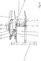
- an inventive vehicle 1 is shown purely schematically.
- the illustrated vehicle 1 is designed as a truck-mounted concrete pump.
- a pivoting bogie 3 is arranged, on which a multi-member mast 4 is constructed.
- the segments of the mast 4 are folded in the illustrated drawing via joints 20 for driving. After unfolding of the mast 4 this is used to distribute concrete on a construction site.
- the concrete is filled via a feed hopper 21 arranged at the rear and conveyed via a concrete pump in delivery lines, not shown, on the mast 4 in order to be able to be distributed over an end hose arranged at the mast top of the unfolded mast 4 (not shown).
- the unfolded mast 4 reaches considerable heights and triggers a depending on the projection and the length of the mast 4 tilting moment.
- the frame support 5, which is connected to the frame 2, carries the tilting moment on the footprint of the vehicle 1 and thereby prevents a turning of the vehicle with the mast 4 during unfolding of the mast 4 or when spreading the concrete.
- the frame support 5 from the vehicle profile extendable horizontal support 6, 6a.
- the mirror-image identical support 6, 6a of the frame support 5 are drawn into the vehicle profile.
- the carriers 6, 6a are each guided on a vehicle-fixed extension section 7, 7a.
- the carriers 6, 6a with the Ausschubabitesen 7, 7a each have a telescope 8, 8a.
- FIG. 1 It can be seen clearly that the vehicle-fixed Ausschubabitese 7, 7a are arranged behind a cab 9 in the direction of travel.
- a respective hinged part 11, 11a is connected via a hinge 10, 10a to the supports 6, 6a.
- a support leg 12, 12 a is arranged, which preferably has a vertically telescoping support leg 22, 22 a with support plate.
- the frame support 5 can be supported on the ground via the support base 22, 22a telescoped against the ground.
- the carrier 6, 6a in retracted transport position.
- the joint 10, 10a is arranged in this position of the carrier 6, 6a outside the Ausschubabiteses 7, 7a, so that the flap part 11, 11a is folded laterally into the vehicle profile in a transport folded position shown.
- the hinge 10, 10a for this folding mechanism forms a vertical pivot axis, which is indicated by dash-dotted lines, and is arranged at the free end of the carrier 6, 6a shown and thus connects the folding part 11, 11a with the carrier 6, 6a.
- the folding part 11, 11 a is the support leg 12, 12 a between the axles 14, 14 a of the double steering axle 13, which is located in the direction of travel between the cab 9 and the Ausschubabites 7, 7 a. From this transport folding position, the folding part 11, 11a can be pivoted laterally before the carrier 6, 6a from the transport position shown here in an extended support position is extendable.
- the installation space for the control electronics / hydraulic system 33 is not affected by the folded forward folding part.
- a tank, tool box or similar could also be used in this area. be housed.
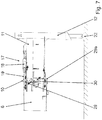
- FIG. 2 shows the vehicle 1 according to FIG. 1 from a bird's eye view.
- the hinge part 10 connected to the carrier 6 folding part 11 is unfolded in Abstützklappwolf.
- In the direction of travel on the right side of the arcuate support 6a is retracted in transport position in Ausschubabêt 7a and connected via the joint 10a with the carrier 6a folding part 11a is folded in transport folding position forward in the direction of the cab 9, so that the folding part 10a laterally in the vehicle profile located.
- the flap part 11b is formed bent from the joint 10a in the direction of the vehicle center 16, a bent embodiment would be possible, for example.
- the support leg 12a can be folded even further into the vehicle profile in the transport folding position, so that larger support feet 22, 22a can be used without them protrude laterally beyond the vehicle profile.
- the support leg 12, 12a arranged on the folding part 11, 11a is located in the transport folding position between the wheel axles 14, 14a of the double-axis 13. From this position, the folding part 11a can first be pivoted into the supporting fold position before the carrier 6a is pulled out of the Ausschubabites 7a. This prevents collisions with the wheel axles 14, 14a.
- the carrier is shown in the direction of travel on the left in pulled out from the Ausschubabites 7 support position.
- the folding part 11 is pivoted into the Abstauerklappwolf by a drive 17 which is formed in the embodiment shown here as a hydraulic cylinder 18.
- This drive 18 is adapted to hold the flap member 11 in the selected Abstützklappwolf.
- the hydraulic cylinder 18 of the drive is articulated on a nose 19, which is located at the free end of the carrier 6. By forming this nose 19, the hydraulic cylinder 18 has a sufficient lever arm to pivot the flap member 11 relative to the carrier 6 about the hinge 10.
- the two Ausschubabitese 7, 7a each have a collar 15, 15a.
- This collar 15, 15a extends opposite the vehicle profile in the direction of the cab 9 obliquely to the vehicle center 16, so that the collar 15, 15a on its side facing the cab 9 28 substantially to the width b of the folding part 11, 11a from the vehicle profile towards the vehicle center 16 is offset.
- the collar 15, 15a extends with respect to the vehicle longitudinal axis in the direction of the driver's cab 9 at an angle of preferably 15 degrees to the vehicle center 16.
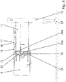
- FIG. 3 is a perspective view of a detail of the carrier 6 and the hinged part 10 connected to the hinge 11 shown.
- the carrier 6 shown here is pulled out of the Ausschubabites 7 and the flap part 11 is located in one Abstützklapp ein.
- the folding part 11 has been pivoted by means of a drive 17, which is formed by a hydraulic cylinder 18.
- This hydraulic cylinder 18 is articulated on a nose 19, which is located at the free end of the carrier 6.
- the hydraulic cylinder 18 has a sufficient lever arm to pivot the flap member 11 relative to the carrier 6 about the hinge 10 around horizontally.
- the folding part 11 is held by the hydraulic cylinder 18, for example by a hydraulic lock with non-return valves, so that its position relative to the carrier 6 is not changed.
- the angular position of the hinged part can be checked by a suitable sensor (angle measurement, limit switch or similar) on the hydraulic cylinder 18 or the joint 10 to ensure that the flap part 11 is fully extended.
- the folding part 11 can optionally bring flexible in different Abstützklappwolfen to adapt the support to the conditions on the site.
- the locking of the folding part 11 relative to the carrier 6 is preferably carried out exclusively via the hydraulic cylinder 18th
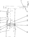
- FIG. 4 shows a detailed perspective view of the frame support 5 and the folding part 11.
- the carrier 6 shown here is in the transport position and is retracted into the Ausschubabrough 7.
- the hinge 10 which connects the flap member 11 with the carrier 6, in this position outside the Ausschubabiteses 7.
- the flap member 11 can be folded into the transport folding position shown.
- the collar 15 which extends at an angle in the direction of the cab 9 to the vehicle center 16, as described above.
- the nose 19 formed on the carrier 6 is guided in the direction of the vehicle center 16 around the collar 15 of the extension section 7. Through this nose 19, the axis of rotation 24 can be positioned as far as possible in the vehicle center 16 for the hydraulic cylinder 18 to provide sufficient installation length and lever arm for the hydraulic cylinder 18 in the transport folding position shown also available.
- FIG. 5 shows a bird's eye view of the frame support 5 and the folding part 11 according to FIG. 4 , It can be seen that the folding part 11 is located in the transport folding position shown within the dot-dash line indicated vehicle profile 25, which indicates the maximum width of the vehicle 1.
- the support 6 nose 19 leads around the collar 15 of the Ausschubabiteses 7 in the direction of the vehicle center 16 and thus provides sufficient lever arm and installation length for the hydraulic cylinder 18, via which the folding part 11 about the hinge 10 from the shown Transportklapp ein in the Abstützklappwolf can be pivoted.
- the joint 10 between the carrier 6 and the flap part 11 is arranged in the transport position of the carrier 6 in the Ausschubabites 7 shown so that it remains outside the Ausschubabites 7.
- the collar 15, 15a extends relative to the vehicle profile in the direction of the cab 9 with an angle ⁇ of preferably 15 ° to the vehicle center 16 out.
- This angle a is illustrated by a further dash-dotted line indicated.
- This offset of the collar 15 relative to the longitudinal side of the vehicle profile 25 ensures that the folding part 11 in the transport position of the carrier 6 in the Ausschubabites 7 via the hinge 10 in Transportklappwolf is folded forward.
- the support leg 22 is slightly offset to the folding part 11 to the center of the vehicle 16 inwardly so that it is in Transportklappwolf the folding part 11 within the vehicle profile.
- FIG. 6 is a perspective detailed view of the frame support 5 and the flap part 11 out.
- a look behind the flap part 11 is possible.
- the frame support 5 has a latching nose 26 which engages in an eyelet 27 on the flap part 11 and thus prevents the carrier 6 is pushed out of the Ausschubabites 7 out before the flap member 11 is not out of the Transportklapp ein was pivoted into a Abstützklapp ein.
- the flap part 11 could also be secured by a locking bolt.
- FIG. 7 shows a detailed perspective view of the joint 10 between the folding part 11 and carrier 6.
- the joint 10 between the folding part 11 and the carrier 6 has a plurality of joint components 29, 29a, 30.
- the middle joint member 30 is configured to transmit vertical forces.
- the forces to be transmitted indicated by dash-dotted arrows.
- the upper 29a and the lower joint component 29 bolts.
- the middle joint component 30 is formed without bolts, since only vertically acting forces are transmitted via support surfaces.
- FIG. 8 shows a hinge 10 between folding part 11 and support 6 according to FIG. 7 however without drawn lines of force. It can be seen that the central joint component 30 for supporting the vertical forces comprises tapered support beams 32, 32a.
- FIG. 9 goes a joint 10 between the folding part 11 and the carrier 6 according to the FIGS. 7 and 8th
- a perspective view is chosen here.
- the support leg 22 of the support leg 12 is retracted and positioned folded down by a tapered collar 31.
- FIG. 1 shows a frame support 5 with arcuate Ausschubabitesen 7, 7a and corresponding supports 6, 6a.
- the basic idea of the invention is, however, in principle, for example, on so-called telescopic X-supports with straight or curved Ausschubabitesen that intersect in front of or behind the turntable or on telescopic supports, in which the carrier are extended perpendicular to the vehicle side applicable.
- the vehicle can also be designed as a so-called truck and trailer truck-mounted concrete pump.
- the cab is part of a towing vehicle, wherein the frame support is part of a trailer articulated to the tractor.
Landscapes
- Engineering & Computer Science (AREA)
- Mechanical Engineering (AREA)
- Physics & Mathematics (AREA)
- Fluid Mechanics (AREA)
- Architecture (AREA)
- Civil Engineering (AREA)
- Structural Engineering (AREA)
- Body Structure For Vehicles (AREA)
- Vehicle Cleaning, Maintenance, Repair, Refitting, And Outriggers (AREA)
- On-Site Construction Work That Accompanies The Preparation And Application Of Concrete (AREA)
Applications Claiming Priority (1)
| Application Number | Priority Date | Filing Date | Title |
|---|---|---|---|
| DE102017122343.6A DE102017122343A1 (de) | 2017-09-26 | 2017-09-26 | Bogenabstützung mit Klappteil |
Publications (2)
| Publication Number | Publication Date |
|---|---|
| EP3459900A1 true EP3459900A1 (fr) | 2019-03-27 |
| EP3459900B1 EP3459900B1 (fr) | 2024-06-26 |
Family
ID=63683683
Family Applications (1)
| Application Number | Title | Priority Date | Filing Date |
|---|---|---|---|
| EP18196441.2A Active EP3459900B1 (fr) | 2017-09-26 | 2018-09-25 | Support de véhicule avec partie rabattable |
Country Status (4)
| Country | Link |
|---|---|
| US (1) | US10464535B2 (fr) |
| EP (1) | EP3459900B1 (fr) |
| CN (1) | CN109552273B (fr) |
| DE (1) | DE102017122343A1 (fr) |
Cited By (1)
| Publication number | Priority date | Publication date | Assignee | Title |
|---|---|---|---|---|
| US11370482B2 (en) * | 2018-08-30 | 2022-06-28 | Master Solutions, Inc. | Hydraulic steering system |
Families Citing this family (3)
| Publication number | Priority date | Publication date | Assignee | Title |
|---|---|---|---|---|
| DE102019122396A1 (de) * | 2019-08-20 | 2021-02-25 | Ffg Flensburger Fahrzeugbau Gesellschaft Mbh | Fahrzeug mit einem eine Mehrzahl von Fahrzeugstützen aufweisenden Stützsystem |
| CN111336376A (zh) * | 2020-04-13 | 2020-06-26 | 徐州徐工施维英机械有限公司 | 支撑装置以及工程机械 |
| CN115142681B (zh) * | 2021-03-31 | 2023-10-27 | 三一汽车制造有限公司 | 工程机械 |
Citations (7)
| Publication number | Priority date | Publication date | Assignee | Title |
|---|---|---|---|---|
| JPS5613243A (en) * | 1979-07-10 | 1981-02-09 | Nissan Diesel Motor Co Ltd | Car body supporter for specially equipped car |
| EP0103434A2 (fr) * | 1982-09-14 | 1984-03-21 | Koehring Company | Assemblage de poutres stabilisatrices pour un véhicule et une méthode pour stabiliser un véhicule |
| DE19736109A1 (de) * | 1997-08-21 | 1999-02-25 | Putzmeister Ag | Fahrbare Arbeitsmaschine mit teleskopierbaren Stützauslegern |
| EP1003655B1 (fr) | 1997-08-21 | 2003-06-18 | PUTZMEISTER Aktiengesellschaft | Machine de travail mobile dotee de bras d'appui telescopiques |
| WO2013082968A1 (fr) * | 2011-12-05 | 2013-06-13 | 中联重科股份有限公司 | Appareil de jambes d'appui et pont roulant |
| DE102013206366A1 (de) * | 2013-04-11 | 2014-10-16 | Putzmeister Engineering Gmbh | Fahrbare Betonpumpe mit Verteilermast und Abstützvorrichtung |
| DE102016104653A1 (de) * | 2016-03-14 | 2017-09-14 | Schwing Gmbh | Doppelt teleskopierbare Bogenabstützung |
Family Cites Families (19)
| Publication number | Priority date | Publication date | Assignee | Title |
|---|---|---|---|---|
| US3825095A (en) * | 1972-10-10 | 1974-07-23 | Pac Craft Prod Inc | Aerial scaffold for vehicle |
| CA997748A (en) * | 1973-11-01 | 1976-09-28 | John T. Hornagold | Mounting arrangement for a vertical outrigger cylinder |
| US4394912A (en) * | 1980-11-07 | 1983-07-26 | Harnischfeger Corporation | Mobile crane having telescoping outriggers and power operated screw means for same |
| DE3830315A1 (de) * | 1988-09-07 | 1990-03-08 | Putzmeister Maschf | Fahrbare betonpumpe |
| US5387071A (en) * | 1993-06-29 | 1995-02-07 | Pinkston; Donald L. | Rotatable recovery vehicle |
| DE4344779C2 (de) * | 1993-12-28 | 1999-12-09 | Schwing Gmbh F | Fahrzeug mit schwenkbar aufgebautem Mast und Rahmenabstützung |
| US6276818B1 (en) * | 2000-02-09 | 2001-08-21 | Hubbell Incorporated | Latch assembly for luminaire housing door |
| DE10032622A1 (de) * | 2000-07-07 | 2002-01-17 | Putzmeister Ag | Stützausleger für fahrbare Arbeitsmaschinen und Autobetonpumpen mit solchen Stützauslegern |
| US7594679B1 (en) * | 2005-01-19 | 2009-09-29 | Westchester Captial, Llc | Outrigger for a boom truck or the like |
| US7338077B2 (en) * | 2005-05-27 | 2008-03-04 | Richard Ronnie J | Storage system for a support mat |
| DE102008007917A1 (de) * | 2008-02-06 | 2009-08-13 | Putzmeister Concrete Pumps Gmbh | Fahrbare Arbeitsmaschine |
| CN101301869B (zh) * | 2008-04-28 | 2011-08-24 | 三一重工股份有限公司 | 一种混凝土泵车的支腿以及具有这种支腿的混凝土泵车 |
| CN201825676U (zh) * | 2010-10-20 | 2011-05-11 | 徐州重型机械有限公司 | 一种支腿支撑装置及移动式起重机 |
| CN102493653A (zh) * | 2011-12-21 | 2012-06-13 | 三一重工股份有限公司 | 一种支腿装置及包括该装置的工程机械 |
| KR101334080B1 (ko) * | 2013-03-19 | 2013-12-04 | 최병언 | 아우트리거 후방 절첩식 파일드라이버 |
| JP6231320B2 (ja) * | 2013-07-23 | 2017-11-15 | 株式会社タダノ | アウトリガ連結ロック装置 |
| DE102014006273A1 (de) * | 2014-05-02 | 2015-11-05 | Schwing Gmbh | Abstützung |
| KR20150137903A (ko) * | 2014-05-30 | 2015-12-09 | 한국타워크레인 주식회사 | 차량 탑재용 크레인 아우트리거 장치 |
| CN204297987U (zh) * | 2014-12-12 | 2015-04-29 | 中联重科股份有限公司 | 一种工程机械的支腿装置及工程机械 |
-
2017
- 2017-09-26 DE DE102017122343.6A patent/DE102017122343A1/de active Pending
-
2018
- 2018-09-25 US US16/140,944 patent/US10464535B2/en active Active
- 2018-09-25 EP EP18196441.2A patent/EP3459900B1/fr active Active
- 2018-09-26 CN CN201811123433.0A patent/CN109552273B/zh active Active
Patent Citations (7)
| Publication number | Priority date | Publication date | Assignee | Title |
|---|---|---|---|---|
| JPS5613243A (en) * | 1979-07-10 | 1981-02-09 | Nissan Diesel Motor Co Ltd | Car body supporter for specially equipped car |
| EP0103434A2 (fr) * | 1982-09-14 | 1984-03-21 | Koehring Company | Assemblage de poutres stabilisatrices pour un véhicule et une méthode pour stabiliser un véhicule |
| DE19736109A1 (de) * | 1997-08-21 | 1999-02-25 | Putzmeister Ag | Fahrbare Arbeitsmaschine mit teleskopierbaren Stützauslegern |
| EP1003655B1 (fr) | 1997-08-21 | 2003-06-18 | PUTZMEISTER Aktiengesellschaft | Machine de travail mobile dotee de bras d'appui telescopiques |
| WO2013082968A1 (fr) * | 2011-12-05 | 2013-06-13 | 中联重科股份有限公司 | Appareil de jambes d'appui et pont roulant |
| DE102013206366A1 (de) * | 2013-04-11 | 2014-10-16 | Putzmeister Engineering Gmbh | Fahrbare Betonpumpe mit Verteilermast und Abstützvorrichtung |
| DE102016104653A1 (de) * | 2016-03-14 | 2017-09-14 | Schwing Gmbh | Doppelt teleskopierbare Bogenabstützung |
Cited By (1)
| Publication number | Priority date | Publication date | Assignee | Title |
|---|---|---|---|---|
| US11370482B2 (en) * | 2018-08-30 | 2022-06-28 | Master Solutions, Inc. | Hydraulic steering system |
Also Published As
| Publication number | Publication date |
|---|---|
| CN109552273B (zh) | 2022-09-06 |
| CN109552273A (zh) | 2019-04-02 |
| US10464535B2 (en) | 2019-11-05 |
| DE102017122343A1 (de) | 2019-03-28 |
| EP3459900B1 (fr) | 2024-06-26 |
| US20190092288A1 (en) | 2019-03-28 |
Similar Documents
| Publication | Publication Date | Title |
|---|---|---|
| EP2931585B1 (fr) | Véhicule de transport à largeur et à voie variables, pourvu d'au moins un essieu directeur | |
| EP2240360B1 (fr) | Engin de travail mobile | |
| EP2238071B1 (fr) | Engin de travail mobile | |
| EP3459900B1 (fr) | Support de véhicule avec partie rabattable | |
| DE1944214C3 (de) | Schienenlos verfahrbarer Dreh kranunterwagen | |
| EP1851159B1 (fr) | Bras d'appui destine a des machines de travail roulantes | |
| CH650299A5 (de) | Schreitbagger. | |
| EP1090195A1 (fr) | Pompe a beton mobile | |
| DE102012024247B4 (de) | Transportfahrzeug mit variabler Breite und Spurweite und mindestens einer Lenkachse | |
| DE112013001318T5 (de) | Geräterahmen mit nach vorne faltbaren Flügeln | |
| DE1915825A1 (de) | Bodenbearbeitungsgeraet | |
| DE202012010545U1 (de) | Schwerlast-Transportfahrzeug zum Transport eines länglichen Objekts | |
| DE2845801C2 (fr) | ||
| DE202007002114U1 (de) | Teleskopische Abstützeinrichtung für mobile Fahrzeuge | |
| DE102012021613B4 (de) | Schwerlast-Transportfahrzeug zum Transport eines länglichen Objekts | |
| WO2014072042A2 (fr) | Véhicule de transport de charges lourdes servant au transport d'un objet allongé | |
| DE102010009176A1 (de) | Vorrichtung zum Abstützen von Sonderfahrzeugen, insbesondere von Autobetonpumpen, und Autobetonpumpe mit einer solchen Vorrichtung | |
| DE202004011990U1 (de) | Umschlaggerät | |
| DE2800119C3 (de) | Klappbarer Geräteträger | |
| DE2808591A1 (de) | Pneumatisches streugeraet | |
| EP3650615B1 (fr) | Pompe à béton automatique | |
| EP3416912B1 (fr) | Unité de bras pour l'accès en hauteur pour une machine mobile pour l'accès en hauteur, machine pour l'accès en hauteur, et utilisation de cette unité de bras pour l'accès en hauteur. | |
| DE1183217B (de) | Fahrzeugkran | |
| DE4135653C2 (de) | Abstützvorrichtung für Sonderfahrzeuge, insbesondere für fahrbare Betonpumpe | |
| DE69400825T2 (de) | Insbesondere landwirtschaftliches Fahrzeug, umfassend von einem Untergestell getragene Arbeitsorgane und einen Rädersatz, sowie Verbindungsmittel zwischen Untergestell und Rädersatz |
Legal Events
| Date | Code | Title | Description |
|---|---|---|---|
| PUAI | Public reference made under article 153(3) epc to a published international application that has entered the european phase |
Free format text: ORIGINAL CODE: 0009012 |
|
| STAA | Information on the status of an ep patent application or granted ep patent |
Free format text: STATUS: THE APPLICATION HAS BEEN PUBLISHED |
|
| AK | Designated contracting states |
Kind code of ref document: A1 Designated state(s): AL AT BE BG CH CY CZ DE DK EE ES FI FR GB GR HR HU IE IS IT LI LT LU LV MC MK MT NL NO PL PT RO RS SE SI SK SM TR |
|
| AX | Request for extension of the european patent |
Extension state: BA ME |
|
| RIN1 | Information on inventor provided before grant (corrected) |
Inventor name: SEGSCHNEIDER, BERND Inventor name: SACKEN, CHRISTOPH |
|
| STAA | Information on the status of an ep patent application or granted ep patent |
Free format text: STATUS: REQUEST FOR EXAMINATION WAS MADE |
|
| 17P | Request for examination filed |
Effective date: 20190926 |
|
| RBV | Designated contracting states (corrected) |
Designated state(s): AL AT BE BG CH CY CZ DE DK EE ES FI FR GB GR HR HU IE IS IT LI LT LU LV MC MK MT NL NO PL PT RO RS SE SI SK SM TR |
|
| STAA | Information on the status of an ep patent application or granted ep patent |
Free format text: STATUS: EXAMINATION IS IN PROGRESS |
|
| 17Q | First examination report despatched |
Effective date: 20210325 |
|
| STAA | Information on the status of an ep patent application or granted ep patent |
Free format text: STATUS: EXAMINATION IS IN PROGRESS |
|
| GRAP | Despatch of communication of intention to grant a patent |
Free format text: ORIGINAL CODE: EPIDOSNIGR1 |
|
| STAA | Information on the status of an ep patent application or granted ep patent |
Free format text: STATUS: GRANT OF PATENT IS INTENDED |
|
| INTG | Intention to grant announced |
Effective date: 20240312 |
|
| GRAS | Grant fee paid |
Free format text: ORIGINAL CODE: EPIDOSNIGR3 |
|
| GRAA | (expected) grant |
Free format text: ORIGINAL CODE: 0009210 |
|
| STAA | Information on the status of an ep patent application or granted ep patent |
Free format text: STATUS: THE PATENT HAS BEEN GRANTED |
|
| AK | Designated contracting states |
Kind code of ref document: B1 Designated state(s): AL AT BE BG CH CY CZ DE DK EE ES FI FR GB GR HR HU IE IS IT LI LT LU LV MC MK MT NL NO PL PT RO RS SE SI SK SM TR |
|
| REG | Reference to a national code |
Ref country code: GB Ref legal event code: FG4D Free format text: NOT ENGLISH |
|
| REG | Reference to a national code |
Ref country code: CH Ref legal event code: EP |
|
| REG | Reference to a national code |
Ref country code: DE Ref legal event code: R096 Ref document number: 502018014766 Country of ref document: DE |