EP3459846B1 - Aéronef à rotors multiples - Google Patents
Aéronef à rotors multiples Download PDFInfo
- Publication number
- EP3459846B1 EP3459846B1 EP16901987.4A EP16901987A EP3459846B1 EP 3459846 B1 EP3459846 B1 EP 3459846B1 EP 16901987 A EP16901987 A EP 16901987A EP 3459846 B1 EP3459846 B1 EP 3459846B1
- Authority
- EP
- European Patent Office
- Prior art keywords
- rotor
- aircraft
- main housing
- fixed
- magnetic medium
- Prior art date
- Legal status (The legal status is an assumption and is not a legal conclusion. Google has not performed a legal analysis and makes no representation as to the accuracy of the status listed.)
- Active
Links
- 230000007246 mechanism Effects 0.000 claims description 15
- 230000000694 effects Effects 0.000 description 5
- 238000010586 diagram Methods 0.000 description 4
- 230000000284 resting effect Effects 0.000 description 2
- 238000004904 shortening Methods 0.000 description 2
- RKTYLMNFRDHKIL-UHFFFAOYSA-N copper;5,10,15,20-tetraphenylporphyrin-22,24-diide Chemical compound [Cu+2].C1=CC(C(=C2C=CC([N-]2)=C(C=2C=CC=CC=2)C=2C=CC(N=2)=C(C=2C=CC=CC=2)C2=CC=C3[N-]2)C=2C=CC=CC=2)=NC1=C3C1=CC=CC=C1 RKTYLMNFRDHKIL-UHFFFAOYSA-N 0.000 description 1
- 230000002708 enhancing effect Effects 0.000 description 1
- 230000001747 exhibiting effect Effects 0.000 description 1
- 238000005339 levitation Methods 0.000 description 1
- 238000000034 method Methods 0.000 description 1
- 238000011160 research Methods 0.000 description 1
- 238000001338 self-assembly Methods 0.000 description 1
Images


Classifications
-
- B—PERFORMING OPERATIONS; TRANSPORTING
- B64—AIRCRAFT; AVIATION; COSMONAUTICS
- B64U—UNMANNED AERIAL VEHICLES [UAV]; EQUIPMENT THEREFOR
- B64U20/00—Constructional aspects of UAVs
- B64U20/30—Constructional aspects of UAVs for safety, e.g. with frangible components
-
- B—PERFORMING OPERATIONS; TRANSPORTING
- B64—AIRCRAFT; AVIATION; COSMONAUTICS
- B64C—AEROPLANES; HELICOPTERS
- B64C27/00—Rotorcraft; Rotors peculiar thereto
- B64C27/20—Rotorcraft characterised by having shrouded rotors, e.g. flying platforms
-
- B—PERFORMING OPERATIONS; TRANSPORTING
- B64—AIRCRAFT; AVIATION; COSMONAUTICS
- B64C—AEROPLANES; HELICOPTERS
- B64C27/00—Rotorcraft; Rotors peculiar thereto
- B64C27/006—Safety devices
-
- B—PERFORMING OPERATIONS; TRANSPORTING
- B64—AIRCRAFT; AVIATION; COSMONAUTICS
- B64C—AEROPLANES; HELICOPTERS
- B64C2211/00—Modular constructions of airplanes or helicopters
-
- B—PERFORMING OPERATIONS; TRANSPORTING
- B64—AIRCRAFT; AVIATION; COSMONAUTICS
- B64U—UNMANNED AERIAL VEHICLES [UAV]; EQUIPMENT THEREFOR
- B64U10/00—Type of UAV
- B64U10/10—Rotorcrafts
-
- B—PERFORMING OPERATIONS; TRANSPORTING
- B64—AIRCRAFT; AVIATION; COSMONAUTICS
- B64U—UNMANNED AERIAL VEHICLES [UAV]; EQUIPMENT THEREFOR
- B64U10/00—Type of UAV
- B64U10/10—Rotorcrafts
- B64U10/13—Flying platforms
-
- B—PERFORMING OPERATIONS; TRANSPORTING
- B64—AIRCRAFT; AVIATION; COSMONAUTICS
- B64U—UNMANNED AERIAL VEHICLES [UAV]; EQUIPMENT THEREFOR
- B64U2201/00—UAVs characterised by their flight controls
- B64U2201/10—UAVs characterised by their flight controls autonomous, i.e. by navigating independently from ground or air stations, e.g. by using inertial navigation systems [INS]
-
- B—PERFORMING OPERATIONS; TRANSPORTING
- B64—AIRCRAFT; AVIATION; COSMONAUTICS
- B64U—UNMANNED AERIAL VEHICLES [UAV]; EQUIPMENT THEREFOR
- B64U2201/00—UAVs characterised by their flight controls
- B64U2201/20—Remote controls
-
- B—PERFORMING OPERATIONS; TRANSPORTING
- B64—AIRCRAFT; AVIATION; COSMONAUTICS
- B64U—UNMANNED AERIAL VEHICLES [UAV]; EQUIPMENT THEREFOR
- B64U30/00—Means for producing lift; Empennages; Arrangements thereof
- B64U30/20—Rotors; Rotor supports
- B64U30/29—Constructional aspects of rotors or rotor supports; Arrangements thereof
- B64U30/291—Detachable rotors or rotor supports
-
- B—PERFORMING OPERATIONS; TRANSPORTING
- B64—AIRCRAFT; AVIATION; COSMONAUTICS
- B64U—UNMANNED AERIAL VEHICLES [UAV]; EQUIPMENT THEREFOR
- B64U50/00—Propulsion; Power supply
- B64U50/10—Propulsion
- B64U50/19—Propulsion using electrically powered motors
Definitions
- the present invention relates to the technical field of unmanned aerial vehicles, and more particularly, to a multi-rotor aircraft.
- the unmanned aerial vehicle in the prior art its rotor mechanism is generally fixed directly to the main housing via a bolt. With this connecting manner in which fixing is achieved directly using a bolt, an external handle is required to drive bolts for the rotor mechanism so as to accomplish its mounting and dismounting.
- a multi-rotor aircraft its rotor mechanisms are often numerous in number. In such case, when several rotor mechanisms of the multi-rotor aircraft require to be mounted or dismounted, the mounting and demounting work would be troublesome, thereby affecting the operation efficiency of workers.
- KR 101373799 B1 discloses a levitation of a robot-assembled honeycomb structure formed by propeller guide.
- CN 103419942 B discloses an unmanned aerial vehicle.
- CN 104608923 A discloses a honeycomb-type six-rotor transport aircraft.
- US 8473123 B2 discloses a programmable surface.
- CN 102556341 A discloses a group flying robot with distribution and self-assembly characteristics.
- the main housing is structured as a hollow regular hexagonal prism, and comprises two oppositely disposed end surfaces and prism faces for connecting the two end surfaces, wherein each of the rotor protection covers is fixed correspondingly to one of the prism faces, wherein the rotor protection cover is structured as a regular hexagon, and an edge on the rotor protection cover that is provided with the pin is fixed to one of the prism faces of the main housing.
- forward directions of rotating shafts of the plurality of rotor systems are identical, and are perpendicular to the end surfaces of the main housing.
- the rotor protection cover comprises first connecting surfaces and a second connecting surface for connecting two of the first connecting surfaces, wherein the pin and the second magnetic medium are provided on the second connecting surface;
- the rotor systems are six in number, wherein the second connecting surface of the rotor protection cover of each rotor system is fixed to one of the prism faces of the main housing, and the first connecting surfaces of two adjacent rotor protection covers abut against each other.
- the multi-rotor aircraft further comprises a third magnetic medium provided on each of the first connecting surfaces, wherein the third magnetic media on two of the first connecting surfaces that abut against each other attract each other.
- the rotor protection cover comprises first connecting surfaces and a second connecting surface for connecting two of the first connecting surfaces, wherein the pin and the second magnetic medium are provided on the second connecting surface;
- the rotor systems are six in number, and the second connecting surface of the rotor protection cover of each rotor system is fixed to one of the prism faces of the main housing, wherein forward directions of rotating shafts of two of the rotor systems that are fixed to two opposite prism faces of the main housing are identical, and are parallel to the end surfaces of the main housing, while those of rotating shafts of the remaining four rotor systems are identical, and are perpendicular to the end surfaces of the main housing.
- the multi-rotor aircraft further comprises a third magnetic medium provided on each of the first connecting surfaces, wherein two of the third magnetic media attract each other.
- the slot has a cruciform shape.
- the main housing comprises a base, a connecting plate and an upper cover, wherein the base and the upper cover constitute two end surfaces, the connecting plate is fixed to a side surface of the base, the slot is formed in the connecting plate, and the control motherboard is fixed to the base.
- the bottom surface of the base is further provided with a supporting point on the outer side opposite to the upper cover.
- the rotor system can be quickly mounted on or dismounted from the main aircraft assembly, thereby achieving the technical effects of shortening the mounting and dismounting time and improving the operation efficiency.
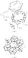
- a multi-rotor aircraft 100 of the present application comprises a main aircraft assembly 10 and rotor systems 20, wherein the rotor systems 20 are numerous in number.
- the main aircraft assembly 10 comprises a first magnetic medium 13, a main housing 11 and a control motherboard (not shown).
- the control motherboard is accommodated in the main housing 11, wherein the main housing 11 comprises two oppositely disposed end surfaces 111 and a plurality of prism faces 112 for connecting the two end surfaces 111, wherein each of the prism faces 112 is provided with the first magnetic medium 13 and the slot 1120, a connection point of the control motherboard is provided in the slot 1120, and the control motherboard is electrically connected with each of the rotor systems 20 via the connection point.
- main aircraft assembly 10 is also provided with a removable battery, an LED indicator lamp, an extension interface, etc.
- these components will not be highlighted herein as they are not the subject matter claimed to be protected in the present invention.
- Each of the rotor systems 20 comprises a rotor mechanism 21, a rotor protection cover 22 and a second magnetic medium 23, wherein the rotor protection cover 22 is of a hollow annular structure, and is fixed outside the rotor mechanism 21 for protecting the rotor mechanism 21.
- the second magnetic medium 23 is fixed to a side surface of the rotor protection cover 22, and attracts the first magnetic medium 13 so as to physically connect the rotor system 20 with the main aircraft assembly 10.
- the side surface is further provided with a pin 2200 that matches the slot 1120, and the rotor system 20 is electrically connected with the control motherboard within the main aircraft assembly 10 via the pin 2200.
- the cooperation of the pin 2200 with the slot 1120 may also hold the relative positions between the rotor system 20 and the main aircraft assembly 10, thereby exhibiting positioning effects.
- the rotor mechanism 21 is a valuable and important component for the multi-rotor aircraft 100, and thus certain measures are required to protect it.
- the rotor protection cover 22 can, to a certain extent, protect the rotor mechanism 21 from being damaged as a result of external factors. Without the protection of the rotor protection cover 22, the rotor mechanism 21 would be likely to scratch a user or other items during rotation. Furthermore, the bare rotor mechanism 21 would also be likely to scratch a user even if it is in the resting state. Accordingly, the rotor protection cover 22 can avoid the above situations to a certain extent.
- the rotor system can be quickly mounted on or dismounted from the main aircraft assembly, thereby achieving the technical effects of shortening the mounting and dismounting time and improving the operation efficiency.
- the main housing 11 is structured as a hollow regular hexagonal prism. More specifically, the main housing 11 comprises a base 113, a connecting plate 115 and an upper cover 114, wherein a bottom surface 1130 of the base 113 and the upper cover 114 constitute two end surfaces 111.
- the base 113 is shaped as a substantially hollow hexagonal prism, and an accommodating chamber is formed between the upper cover 114 and the base 113.
- the control motherboard is fixed in the accommodating chamber, i.e. that it is fixed to the base 113.
- the connecting plate 115 is fixed on a side wall 1131 of the base 113. In other words, the connecting plate 115 is fixed on each side wall 1131.
- the side walls 1131 and the connecting plates 115 cooperate to constitute the prism faces 112 of the main housing.
- the slot 1120 is formed in the connecting plate 115.
- the second magnetic medium 23 is fixed to the connecting plate 115.
- the bottom surface 1130 of the base 113 is further provided with a supporting point 1132 on the outer side opposite to the upper cover 114, wherein the supporting point is used for supporting the multi-rotor aircraft 100.
- the rotor protection cover 22 is structured as a regular hexagon, wherein the size of the regular hexagon is substantially the same as that of the cross-section of the regular hexagonal prism, and each of the rotor systems 20 is fixed to one of the prism faces 112 of the main housing 11 through the rotor protection cover 22. Further, the rotor protection cover 22 comprises a connecting member 221 and a housing 222 in the shape of a regular hexagon, and the housing 222 comprises two first side surfaces 2221 and a second side surface 2222 connected between the two first side surfaces 2221. The first side surfaces 2221 of the housing 222 are provided with connecting card slots 2224.
- the generally ⁇ -shaped connecting member 221 comprises two first connecting surfaces 2211 (namely the first connecting surfaces of the rotor protection cover) and a second connecting surface 2212 (namely the second connecting surface of the rotor protection cover) for connecting two of the first connecting surfaces 2211, wherein the first connecting surfaces 2211 of the connecting member are fixed in the connecting card slots 2224, and the second connecting surface 2212 directly faces the second side surface 2222.
- the second connecting surface 2212 of the connecting member is provided with the pin 2200 on the side distal to the rotor protection cover 22.
- the second magnetic medium 23 is fixed between the housing 222 and the connecting member 221.
- the pin 1120 comprises a boss (not numbered) and a bouncing pin (not shown) fixed to the boss, wherein the bouncing pin is used for connection with the connection point of the control motherboard.
- the plurality of rotor systems 20 in the first embodiment of the present application are six in number, wherein the six rotor systems 20 are evenly distributed outside the main housing 11, and each of them is fixed to one of the connecting plates 115.
- the second connecting surface of the rotor protection cover 22 of each rotor system 20 is fixed to one of the prism faces 112 of the main housing 11, and the first connecting surfaces 2211 of two adjacent rotor protection covers 22 abut against each other.
- the rotating shafts of the six rotor systems 20 all are perpendicular to the end surfaces 111 of the main housing, and forward directions of the rotating shafts of the plurality of rotor systems 20 are identical.
- the first connecting surfaces 2211 of two adjacent rotor protection covers 22 abut against each other, such that the operation shaking of the rotor systems 20 can be reduced, thereby improving the stability of the multi-rotor aircraft.
- first connecting surfaces 2211 of the connecting member 221 are each provided with a third magnetic medium (not shown).
- the mutual attraction between the third magnetic media on the first connecting surfaces of adjacent connecting members may act to fix the plurality of rotor systems 20 more securely, thus further enhancing the stability of the multi-rotor aircraft.
- the slot 1120 has a substantially cruciform shape.
- the pin 2200 has a cruciform shape.
- the advantage of such design is that the angle of the rotor systems 20 may be adjusted according to different requirements, thereby achieving multiple flying modes.
- the plurality of rotor systems 20 in the second embodiment of the present application are six in number, and each of the rotor systems 20 is fixed to one of the side surfaces of the main housing, wherein forward directions of the rotating shafts of two oppositely disposed rotor systems 20 are identical, and are parallel to the end surfaces 111 of the main housing 11, while the rotating shafts of the remaining four rotor systems 20 are perpendicular to the end surfaces 111 of the main housing, and their forward directions are identical.
- a pair of oppositely disposed rotor systems 20 can be rotated by 90 degrees along the center of the cruciform shape (namely in the direction along which the rotating shafts are parallel to the end surfaces 111), thereby achieving the technical effects that the multi-rotor aircraft does not need to fly forwards/backwards in a slant manner (namely in the direction along which the rotating shafts are parallel to the end surfaces 111).
- the number of rotor systems 20 may be four, three, two, etc. Different functions can be achieved by arranging the number and axial directions of the rotor systems 20, which will not be exhaustively enumerated herein.
- slot 1120 may also be in the shape of a hexagon, a tetragon, etc.
- the positions of the slot and the pin can be interchanged.
- the pin is provided on the main aircraft assembly, while the slot is provided on the rotor system, and the resultant effects are identical.
- the main housing 11 in the present application may also be in the shape of a regular trigonal prism, a regular tetragonal prism, a regular pentagonal prism, etc.
- the housing 222 is in the shape of a regular triangle, a square, a regular pentagon, etc.
Landscapes
- Engineering & Computer Science (AREA)
- Mechanical Engineering (AREA)
- Aviation & Aerospace Engineering (AREA)
- Remote Sensing (AREA)
- Details Of Aerials (AREA)
- Dynamo-Electric Clutches, Dynamo-Electric Brakes (AREA)
- Shielding Devices Or Components To Electric Or Magnetic Fields (AREA)
- Connection Of Plates (AREA)
Claims (10)
- Aéronef multi-rotor (100), comprenant:un ensemble principal d'aéronef (10), comprenant un boîtier principal (11) et une carte mère de commande logée dans le boîtier principal (11), où une fente (1120) est par ailleurs prévue sur le boîtier principal (11), et un point de connexion de la carte mère de commande est prévue dans la fente (1120) ;une pluralité de systèmes de rotor (20), où chacun de la pluralité de systèmes de rotor (20) comprend un mécanisme de rotor (21) et un couvercle de protection de rotor (22) qui est d'une structure annulaire creuse et est fixé à l'extérieur du mécanisme de rotor (21); etune goupille (2200) correspondant à la fente (1120);dans lequel le système de rotor (20) est positionné sur et connecté électriquement à l'ensemble principal d'aéronef (10) au moyen de la coopération de la goupille (2200) avec la fente (1120),caractérisé par le fait quel'ensemble principal d'aéronef (10) comprend par ailleurs un premier support magnétique (13) prévu sur le boîtier principal (11);chacun de la pluralité de systèmes de rotor (20) comprend par ailleurs un deuxième support magnétique (23) fixé au couvercle de protection de rotor (22) et attirant le premier support magnétique (13);la goupille (2200) est prévue sur le couvercle de protection du rotor (22); etle système de rotor (20) est également fixé à l'ensemble principal d'aéronef (10) par la force magnétique entre le premier support magnétique (13) et le deuxième support magnétique (23).
- Aéronef multi-rotor (100) selon la revendication 1, caractérisé par le fait que le boîtier principal (11) est structuré en forme de prisme hexagonal régulier creux, et comprend deux surfaces d'extrémité (111) disposées opposées l'une à l'autre et des faces de prisme (112) destinées à connecter les deux surfaces d'extrémité (111), dans lequel chacun des couvercles de protection de rotor (22) est fixé en correspondance à l'une des faces de prisme (112), dans lequel le couvercle de protection de rotor (22) est structuré en forme d'hexagone, et un bord sur le couvercle de protection de rotor (22) qui est pourvu de la goupille (2200) est fixé à l'une des faces de prisme (112) du boîtier principal (11).
- Aéronef multi-rotor (100) selon la revendication 2, caractérisé par le fait que les directions en avant des arbres rotatifs de la pluralité de systèmes de rotor (20) sont identiques et perpendiculaires aux surfaces d'extrémité (111) du boîtier principal (11).
- Aéronef multi-rotor (100) selon la revendication 2 ou 3, caractérisé par le fait que le couvercle de protection de rotor (22) comprend des premières surfaces de connexion (2211) et une deuxième surface de connexion (2212) destinée à connecter deux des premières surfaces de connexion (2211), dans lequel la goupille (2200) et le deuxième support magnétique (23) sont prévus sur la deuxième surface de connexion (2212), dans lequel les systèmes de rotor (20) sont au nombre de six, la deuxième surface de connexion (2212) du couvercle de protection de rotor (22) de chaque système de rotor (20) est fixée à l'une des faces de prisme (112) du boîtier principal (11), et les premières surfaces de connexion (2211) de deux couvercles de protection de rotor adjacents (22) viennent en butée l'une contre l'autre.
- Aéronef multi-rotor (100) selon la revendication 4, caractérisé par le fait que l'aéronef multi-rotor (100) comprend par ailleurs un troisième support magnétique prévu sur chacune des premières surfaces de connexion (2211), dans lequel les troisièmes supports magnétiques sur deux des premières surfaces de connexion (2211) qui viennent en butée l'une contre l'autre s'attirent entre eux.
- Aéronef multi-rotor (100) selon la revendication 2, caractérisé par le fait que le couvercle de protection de rotor comprend des premières surfaces de connexion (2211) et une deuxième surface de connexion (2212) destinée à connecter deux des premières surfaces de connexion (2211), et la goupille (2200) et le deuxième support magnétique (23) sont prévus sur la deuxième surface de connexion (2212), dans lequel les systèmes de rotor (20) sont au nombre de six, et la deuxième surface de connexion (2212) du couvercle de protection de rotor de chaque système de rotor (20) est fixée à l'une des faces de prisme (112) du boîtier principal (11), dans lequel les directions en avant des arbres rotatifs de deux des systèmes de rotor (20) qui sont fixés à deux faces de prisme opposées (112) du boîtier principal (11) sont identiques et sont parallèles aux surfaces d'extrémité (111) du boîtier principal (11), tandis que celles des arbres rotatifs des quatre systèmes de rotor restants (20) sont identiques et perpendiculaires aux surfaces d'extrémité (111) du boîtier principal (11).
- Aéronef multi-rotor (100) selon la revendication 6, caractérisé par le fait que l'aéronef multi-rotor (100) comprend par ailleurs un troisième support magnétique prévu sur chacune des premières surfaces de connexion (2211), dans lequel deux des troisièmes supports magnétiques s'attirent entre eux.
- Aéronef multi-rotor (100) selon la revendication 1, caractérisé par le fait que la fente (1120) présente une forme cruciforme.
- Aéronef multi-rotor (100) selon la revendication 1, caractérisé par le fait que le boîtier principal (11) comprend une embase (113), une plaque de connexion (115) et un couvercle supérieur (114), dans lequel l'embase (113) et le couvercle supérieur (114) constituent les deux surfaces d'extrémité (111), la plaque de connexion (115) est fixée à une surface latérale (1131) de l'embase (113), la fente (1120) est formée dans la plaque de connexion (115), et la carte mère de commande est fixée à l'embase (113).
- Aéronef multi-rotor (100) selon la revendication 9, caractérisé par le fait que la surface inférieure (1130) de l'embase (113) est par ailleurs pourvue d'un point d'appui (1132) du côté extérieur opposé au couvercle supérieur (114).
Applications Claiming Priority (1)
| Application Number | Priority Date | Filing Date | Title |
|---|---|---|---|
| PCT/CN2016/082496 WO2017197602A1 (fr) | 2016-05-18 | 2016-05-18 | Aéronef à rotors multiples |
Publications (3)
| Publication Number | Publication Date |
|---|---|
| EP3459846A1 EP3459846A1 (fr) | 2019-03-27 |
| EP3459846A4 EP3459846A4 (fr) | 2020-01-15 |
| EP3459846B1 true EP3459846B1 (fr) | 2021-04-21 |
Family
ID=58952987
Family Applications (1)
| Application Number | Title | Priority Date | Filing Date |
|---|---|---|---|
| EP16901987.4A Active EP3459846B1 (fr) | 2016-05-18 | 2016-05-18 | Aéronef à rotors multiples |
Country Status (4)
| Country | Link |
|---|---|
| US (1) | US11027832B2 (fr) |
| EP (1) | EP3459846B1 (fr) |
| CN (1) | CN106794895B (fr) |
| WO (1) | WO2017197602A1 (fr) |
Families Citing this family (10)
| Publication number | Priority date | Publication date | Assignee | Title |
|---|---|---|---|---|
| PL232731B1 (pl) * | 2017-07-03 | 2019-07-31 | Wawrzynski Pawel | Multikopter z wirnikami o zmiennym kącie natarcia i sposób sterowania jego lotem |
| PL232732B1 (pl) * | 2017-07-03 | 2019-07-31 | Wawrzynski Pawel | Pojazd latający z kilkoma zespołami napędowymi i sposób sterowania jego lotem |
| DE102017119670A1 (de) * | 2017-08-28 | 2019-02-28 | Airbus Operations Gmbh | Kopplungseinrichtung zum Koppeln von Modulen, Luftfahrzeug mit Kopplungseinrichtung, Verfahren zum Koppeln und Entkoppeln von Modulen |
| CN108216629A (zh) * | 2018-02-26 | 2018-06-29 | 西北工业大学 | 一种组合式运输无人机 |
| US10954679B2 (en) * | 2018-06-11 | 2021-03-23 | International Business Machines Corporation | Dynamic platform creation |
| CN109515702A (zh) * | 2019-01-15 | 2019-03-26 | 张轶南 | 一种便携式、模块化、可扩展3d打印多旋翼无人机 |
| US11673657B2 (en) * | 2019-05-03 | 2023-06-13 | The Boeing Company | Multi-rotor rotorcraft |
| US11958601B2 (en) * | 2020-04-14 | 2024-04-16 | Aurora Flight Sciences Corporation | Unmanned aerial aquatic platform with battery management |
| CN112550703B (zh) * | 2020-11-13 | 2023-05-23 | 安徽文达信息工程学院 | 一种定点监控无人机 |
| JP7144897B1 (ja) | 2022-07-26 | 2022-09-30 | 株式会社エムアイエー | 機体フレーム |
Family Cites Families (15)
| Publication number | Priority date | Publication date | Assignee | Title |
|---|---|---|---|---|
| US8473123B2 (en) * | 2010-02-18 | 2013-06-25 | Massachusetts Institute Of Technology | Programmable surface |
| CN101992854B (zh) * | 2010-11-03 | 2012-11-07 | 中国科学院长春光学精密机械与物理研究所 | 一种可折叠的六轴多旋翼飞行器 |
| CN102556341B (zh) | 2011-12-05 | 2013-11-13 | 北京航空航天大学 | 具有分布式和自组装特征的群体飞行机器人 |
| US8794564B2 (en) * | 2012-08-02 | 2014-08-05 | Neurosciences Research Foundation, Inc. | Vehicle capable of in-air and on-ground mobility |
| KR101373799B1 (ko) * | 2012-10-24 | 2014-03-14 | 김영진 | 공중 부양 로봇의 벌집 구조로 형성된 조립형 프로펠러 가이드 |
| US9139130B2 (en) | 2013-06-06 | 2015-09-22 | Douglas J. Wolfe | Light component coordination |
| CN103419942B (zh) * | 2013-09-10 | 2015-08-05 | 北京臻迪科技有限公司 | 一种无人飞行器 |
| DE102014100027B4 (de) * | 2014-01-02 | 2018-01-18 | Hung-Fu Lee | Hubschrauber mit einem H-förmigen Aufbau |
| JP6268659B2 (ja) * | 2014-08-08 | 2018-01-31 | エスゼット ディージェイアイ テクノロジー カンパニー リミテッドSz Dji Technology Co.,Ltd | Uavエネルギー交換ステーション |
| CN104276276A (zh) * | 2014-10-08 | 2015-01-14 | 中国航空工业集团公司西安飞机设计研究所 | 一种模块化吊运无人机布局 |
| CN104260879B (zh) | 2014-10-16 | 2017-05-03 | 深圳市科卫泰实业发展有限公司 | 具有快速拆装的高可靠性和高平稳性的多旋翼无人飞行器 |
| CN204998752U (zh) * | 2015-01-04 | 2016-01-27 | 北京零零无限科技有限公司 | 一种可折叠的无人机 |
| CN104608923B (zh) * | 2015-01-31 | 2016-05-11 | 中南大学 | 一种蜂窝式六旋翼运输飞行器 |
| WO2016209334A2 (fr) * | 2015-04-13 | 2016-12-29 | Geise David | Véhicule volant à multiples rotors |
| CN205675237U (zh) * | 2016-05-18 | 2016-11-09 | 深圳市创客工场科技有限公司 | 多旋翼飞行器 |
-
2016
- 2016-05-18 WO PCT/CN2016/082496 patent/WO2017197602A1/fr unknown
- 2016-05-18 US US16/302,217 patent/US11027832B2/en active Active
- 2016-05-18 CN CN201680002954.3A patent/CN106794895B/zh active Active
- 2016-05-18 EP EP16901987.4A patent/EP3459846B1/fr active Active
Non-Patent Citations (1)
| Title |
|---|
| None * |
Also Published As
| Publication number | Publication date |
|---|---|
| CN106794895B (zh) | 2020-04-17 |
| CN106794895A (zh) | 2017-05-31 |
| US20190291855A1 (en) | 2019-09-26 |
| EP3459846A4 (fr) | 2020-01-15 |
| EP3459846A1 (fr) | 2019-03-27 |
| WO2017197602A1 (fr) | 2017-11-23 |
| US11027832B2 (en) | 2021-06-08 |
Similar Documents
| Publication | Publication Date | Title |
|---|---|---|
| EP3459846B1 (fr) | Aéronef à rotors multiples | |
| US11155335B2 (en) | Driving device, propeller and propulsion system | |
| CN205113731U (zh) | 一种全保护无人机 | |
| KR20130109986A (ko) | 재구성가능한 배터리-작동식 운행체 시스템 | |
| EP3795474B1 (fr) | Véhicule aérien sans pilote | |
| EP2772429A1 (fr) | Aéronef à quatre rotors | |
| CN108001668B (zh) | 螺旋桨、螺旋桨套件、动力组件、动力套件及无人机 | |
| AU2019399622B2 (en) | Frame for aircraft and aircraft | |
| CN109890699A (zh) | 螺旋桨、动力系统及无人飞行器 | |
| CN112744104B (zh) | 无人机降落充电装置和无人机系统 | |
| CN104843182A (zh) | 多旋翼飞行器及机臂夹持装置与夹持机构 | |
| CN109562838A (zh) | 无人机 | |
| CN105620726A (zh) | 螺旋桨定桨器和无人机 | |
| JP2021070469A (ja) | ロータマウントアセンブリ、ロータシート、推進システム、および無人航空機(uav) | |
| KR101665236B1 (ko) | 무인 비행체의 멀티 로터 프레임 및 이를 이용한 프레임의 조립 방법 | |
| CN205615707U (zh) | 螺旋桨定桨器和无人机 | |
| US20210331783A1 (en) | A Propeller Driving Unit | |
| WO2022077290A1 (fr) | Engin volant sans pilote embarqué à rotors multiples | |
| US11309768B2 (en) | Motor and motor fixing structure | |
| US20200283143A1 (en) | Non-planar frame structure of an unmanned aerial vehicle | |
| CN108001678B (zh) | 一种用于无人机的可变旋翼连接装置 | |
| CN109383760B (zh) | 可快拆的螺旋桨结构及无人机 | |
| CN208248498U (zh) | 一种六芒星型多旋翼无人机 | |
| CN205952312U (zh) | 旋翼保护架的连接组件、无人多旋翼飞行器 | |
| WO2020103055A1 (fr) | Ensemble rotor et véhicule aérien sans pilote |
Legal Events
| Date | Code | Title | Description |
|---|---|---|---|
| STAA | Information on the status of an ep patent application or granted ep patent |
Free format text: STATUS: THE INTERNATIONAL PUBLICATION HAS BEEN MADE |
|
| PUAI | Public reference made under article 153(3) epc to a published international application that has entered the european phase |
Free format text: ORIGINAL CODE: 0009012 |
|
| STAA | Information on the status of an ep patent application or granted ep patent |
Free format text: STATUS: REQUEST FOR EXAMINATION WAS MADE |
|
| 17P | Request for examination filed |
Effective date: 20181114 |
|
| AK | Designated contracting states |
Kind code of ref document: A1 Designated state(s): AL AT BE BG CH CY CZ DE DK EE ES FI FR GB GR HR HU IE IS IT LI LT LU LV MC MK MT NL NO PL PT RO RS SE SI SK SM TR |
|
| AX | Request for extension of the european patent |
Extension state: BA ME |
|
| DAV | Request for validation of the european patent (deleted) | ||
| DAX | Request for extension of the european patent (deleted) | ||
| A4 | Supplementary search report drawn up and despatched |
Effective date: 20191218 |
|
| RIC1 | Information provided on ipc code assigned before grant |
Ipc: B64C 27/08 20060101AFI20191212BHEP Ipc: B64C 27/20 20060101ALI20191212BHEP |
|
| GRAP | Despatch of communication of intention to grant a patent |
Free format text: ORIGINAL CODE: EPIDOSNIGR1 |
|
| STAA | Information on the status of an ep patent application or granted ep patent |
Free format text: STATUS: GRANT OF PATENT IS INTENDED |
|
| INTG | Intention to grant announced |
Effective date: 20201104 |
|
| RIN1 | Information on inventor provided before grant (corrected) |
Inventor name: WANG, JIANJUN |
|
| GRAS | Grant fee paid |
Free format text: ORIGINAL CODE: EPIDOSNIGR3 |
|
| GRAA | (expected) grant |
Free format text: ORIGINAL CODE: 0009210 |
|
| STAA | Information on the status of an ep patent application or granted ep patent |
Free format text: STATUS: THE PATENT HAS BEEN GRANTED |
|
| AK | Designated contracting states |
Kind code of ref document: B1 Designated state(s): AL AT BE BG CH CY CZ DE DK EE ES FI FR GB GR HR HU IE IS IT LI LT LU LV MC MK MT NL NO PL PT RO RS SE SI SK SM TR |
|
| REG | Reference to a national code |
Ref country code: GB Ref legal event code: FG4D |
|
| REG | Reference to a national code |
Ref country code: CH Ref legal event code: EP |
|
| REG | Reference to a national code |
Ref country code: DE Ref legal event code: R096 Ref document number: 602016056701 Country of ref document: DE Ref country code: IE Ref legal event code: FG4D |
|
| REG | Reference to a national code |
Ref country code: AT Ref legal event code: REF Ref document number: 1384377 Country of ref document: AT Kind code of ref document: T Effective date: 20210515 |
|
| REG | Reference to a national code |
Ref country code: LT Ref legal event code: MG9D |
|
| REG | Reference to a national code |
Ref country code: AT Ref legal event code: MK05 Ref document number: 1384377 Country of ref document: AT Kind code of ref document: T Effective date: 20210421 |
|
| REG | Reference to a national code |
Ref country code: NL Ref legal event code: MP Effective date: 20210421 |
|
| PG25 | Lapsed in a contracting state [announced via postgrant information from national office to epo] |
Ref country code: FI Free format text: LAPSE BECAUSE OF FAILURE TO SUBMIT A TRANSLATION OF THE DESCRIPTION OR TO PAY THE FEE WITHIN THE PRESCRIBED TIME-LIMIT Effective date: 20210421 Ref country code: LT Free format text: LAPSE BECAUSE OF FAILURE TO SUBMIT A TRANSLATION OF THE DESCRIPTION OR TO PAY THE FEE WITHIN THE PRESCRIBED TIME-LIMIT Effective date: 20210421 Ref country code: NL Free format text: LAPSE BECAUSE OF FAILURE TO SUBMIT A TRANSLATION OF THE DESCRIPTION OR TO PAY THE FEE WITHIN THE PRESCRIBED TIME-LIMIT Effective date: 20210421 Ref country code: HR Free format text: LAPSE BECAUSE OF FAILURE TO SUBMIT A TRANSLATION OF THE DESCRIPTION OR TO PAY THE FEE WITHIN THE PRESCRIBED TIME-LIMIT Effective date: 20210421 Ref country code: BG Free format text: LAPSE BECAUSE OF FAILURE TO SUBMIT A TRANSLATION OF THE DESCRIPTION OR TO PAY THE FEE WITHIN THE PRESCRIBED TIME-LIMIT Effective date: 20210721 Ref country code: AT Free format text: LAPSE BECAUSE OF FAILURE TO SUBMIT A TRANSLATION OF THE DESCRIPTION OR TO PAY THE FEE WITHIN THE PRESCRIBED TIME-LIMIT Effective date: 20210421 |
|
| PG25 | Lapsed in a contracting state [announced via postgrant information from national office to epo] |
Ref country code: LV Free format text: LAPSE BECAUSE OF FAILURE TO SUBMIT A TRANSLATION OF THE DESCRIPTION OR TO PAY THE FEE WITHIN THE PRESCRIBED TIME-LIMIT Effective date: 20210421 Ref country code: GR Free format text: LAPSE BECAUSE OF FAILURE TO SUBMIT A TRANSLATION OF THE DESCRIPTION OR TO PAY THE FEE WITHIN THE PRESCRIBED TIME-LIMIT Effective date: 20210722 Ref country code: IS Free format text: LAPSE BECAUSE OF FAILURE TO SUBMIT A TRANSLATION OF THE DESCRIPTION OR TO PAY THE FEE WITHIN THE PRESCRIBED TIME-LIMIT Effective date: 20210821 Ref country code: PT Free format text: LAPSE BECAUSE OF FAILURE TO SUBMIT A TRANSLATION OF THE DESCRIPTION OR TO PAY THE FEE WITHIN THE PRESCRIBED TIME-LIMIT Effective date: 20210823 Ref country code: NO Free format text: LAPSE BECAUSE OF FAILURE TO SUBMIT A TRANSLATION OF THE DESCRIPTION OR TO PAY THE FEE WITHIN THE PRESCRIBED TIME-LIMIT Effective date: 20210721 Ref country code: PL Free format text: LAPSE BECAUSE OF FAILURE TO SUBMIT A TRANSLATION OF THE DESCRIPTION OR TO PAY THE FEE WITHIN THE PRESCRIBED TIME-LIMIT Effective date: 20210421 Ref country code: SE Free format text: LAPSE BECAUSE OF FAILURE TO SUBMIT A TRANSLATION OF THE DESCRIPTION OR TO PAY THE FEE WITHIN THE PRESCRIBED TIME-LIMIT Effective date: 20210421 Ref country code: RS Free format text: LAPSE BECAUSE OF FAILURE TO SUBMIT A TRANSLATION OF THE DESCRIPTION OR TO PAY THE FEE WITHIN THE PRESCRIBED TIME-LIMIT Effective date: 20210421 |
|
| REG | Reference to a national code |
Ref country code: CH Ref legal event code: PL |
|
| REG | Reference to a national code |
Ref country code: DE Ref legal event code: R097 Ref document number: 602016056701 Country of ref document: DE |
|
| PG25 | Lapsed in a contracting state [announced via postgrant information from national office to epo] |
Ref country code: SM Free format text: LAPSE BECAUSE OF FAILURE TO SUBMIT A TRANSLATION OF THE DESCRIPTION OR TO PAY THE FEE WITHIN THE PRESCRIBED TIME-LIMIT Effective date: 20210421 Ref country code: SK Free format text: LAPSE BECAUSE OF FAILURE TO SUBMIT A TRANSLATION OF THE DESCRIPTION OR TO PAY THE FEE WITHIN THE PRESCRIBED TIME-LIMIT Effective date: 20210421 Ref country code: ES Free format text: LAPSE BECAUSE OF FAILURE TO SUBMIT A TRANSLATION OF THE DESCRIPTION OR TO PAY THE FEE WITHIN THE PRESCRIBED TIME-LIMIT Effective date: 20210421 Ref country code: RO Free format text: LAPSE BECAUSE OF FAILURE TO SUBMIT A TRANSLATION OF THE DESCRIPTION OR TO PAY THE FEE WITHIN THE PRESCRIBED TIME-LIMIT Effective date: 20210421 Ref country code: DK Free format text: LAPSE BECAUSE OF FAILURE TO SUBMIT A TRANSLATION OF THE DESCRIPTION OR TO PAY THE FEE WITHIN THE PRESCRIBED TIME-LIMIT Effective date: 20210421 Ref country code: EE Free format text: LAPSE BECAUSE OF FAILURE TO SUBMIT A TRANSLATION OF THE DESCRIPTION OR TO PAY THE FEE WITHIN THE PRESCRIBED TIME-LIMIT Effective date: 20210421 Ref country code: CZ Free format text: LAPSE BECAUSE OF FAILURE TO SUBMIT A TRANSLATION OF THE DESCRIPTION OR TO PAY THE FEE WITHIN THE PRESCRIBED TIME-LIMIT Effective date: 20210421 Ref country code: CH Free format text: LAPSE BECAUSE OF NON-PAYMENT OF DUE FEES Effective date: 20210531 Ref country code: MC Free format text: LAPSE BECAUSE OF FAILURE TO SUBMIT A TRANSLATION OF THE DESCRIPTION OR TO PAY THE FEE WITHIN THE PRESCRIBED TIME-LIMIT Effective date: 20210421 Ref country code: LI Free format text: LAPSE BECAUSE OF NON-PAYMENT OF DUE FEES Effective date: 20210531 Ref country code: LU Free format text: LAPSE BECAUSE OF NON-PAYMENT OF DUE FEES Effective date: 20210518 |
|
| REG | Reference to a national code |
Ref country code: BE Ref legal event code: MM Effective date: 20210531 |
|
| PLBE | No opposition filed within time limit |
Free format text: ORIGINAL CODE: 0009261 |
|
| STAA | Information on the status of an ep patent application or granted ep patent |
Free format text: STATUS: NO OPPOSITION FILED WITHIN TIME LIMIT |
|
| GBPC | Gb: european patent ceased through non-payment of renewal fee |
Effective date: 20210721 |
|
| 26N | No opposition filed |
Effective date: 20220124 |
|
| PG25 | Lapsed in a contracting state [announced via postgrant information from national office to epo] |
Ref country code: IE Free format text: LAPSE BECAUSE OF NON-PAYMENT OF DUE FEES Effective date: 20210518 Ref country code: GB Free format text: LAPSE BECAUSE OF NON-PAYMENT OF DUE FEES Effective date: 20210721 |
|
| PG25 | Lapsed in a contracting state [announced via postgrant information from national office to epo] |
Ref country code: IS Free format text: LAPSE BECAUSE OF FAILURE TO SUBMIT A TRANSLATION OF THE DESCRIPTION OR TO PAY THE FEE WITHIN THE PRESCRIBED TIME-LIMIT Effective date: 20210821 Ref country code: FR Free format text: LAPSE BECAUSE OF NON-PAYMENT OF DUE FEES Effective date: 20210621 Ref country code: AL Free format text: LAPSE BECAUSE OF FAILURE TO SUBMIT A TRANSLATION OF THE DESCRIPTION OR TO PAY THE FEE WITHIN THE PRESCRIBED TIME-LIMIT Effective date: 20210421 |
|
| PG25 | Lapsed in a contracting state [announced via postgrant information from national office to epo] |
Ref country code: IT Free format text: LAPSE BECAUSE OF FAILURE TO SUBMIT A TRANSLATION OF THE DESCRIPTION OR TO PAY THE FEE WITHIN THE PRESCRIBED TIME-LIMIT Effective date: 20210421 Ref country code: BE Free format text: LAPSE BECAUSE OF NON-PAYMENT OF DUE FEES Effective date: 20210531 |
|
| PG25 | Lapsed in a contracting state [announced via postgrant information from national office to epo] |
Ref country code: CY Free format text: LAPSE BECAUSE OF FAILURE TO SUBMIT A TRANSLATION OF THE DESCRIPTION OR TO PAY THE FEE WITHIN THE PRESCRIBED TIME-LIMIT Effective date: 20210421 |
|
| PG25 | Lapsed in a contracting state [announced via postgrant information from national office to epo] |
Ref country code: HU Free format text: LAPSE BECAUSE OF FAILURE TO SUBMIT A TRANSLATION OF THE DESCRIPTION OR TO PAY THE FEE WITHIN THE PRESCRIBED TIME-LIMIT; INVALID AB INITIO Effective date: 20160518 |
|
| PGFP | Annual fee paid to national office [announced via postgrant information from national office to epo] |
Ref country code: DE Payment date: 20230530 Year of fee payment: 8 |
|
| PG25 | Lapsed in a contracting state [announced via postgrant information from national office to epo] |
Ref country code: MK Free format text: LAPSE BECAUSE OF FAILURE TO SUBMIT A TRANSLATION OF THE DESCRIPTION OR TO PAY THE FEE WITHIN THE PRESCRIBED TIME-LIMIT Effective date: 20210421 |