EP3459809B1 - Zugvorrichtung für drehgestellaufhängung zur verwendung bei einem niederflur-gelenkschienenfahrzeug - Google Patents
Zugvorrichtung für drehgestellaufhängung zur verwendung bei einem niederflur-gelenkschienenfahrzeug Download PDFInfo
- Publication number
- EP3459809B1 EP3459809B1 EP17802067.3A EP17802067A EP3459809B1 EP 3459809 B1 EP3459809 B1 EP 3459809B1 EP 17802067 A EP17802067 A EP 17802067A EP 3459809 B1 EP3459809 B1 EP 3459809B1
- Authority
- EP
- European Patent Office
- Prior art keywords
- swing bolster
- bogie
- frame
- rod
- lifting
- Prior art date
- Legal status (The legal status is an assumption and is not a legal conclusion. Google has not performed a legal analysis and makes no representation as to the accuracy of the status listed.)
- Active
Links
Images





Classifications
-
- B—PERFORMING OPERATIONS; TRANSPORTING
- B61—RAILWAYS
- B61F—RAIL VEHICLE SUSPENSIONS, e.g. UNDERFRAMES, BOGIES OR ARRANGEMENTS OF WHEEL AXLES; RAIL VEHICLES FOR USE ON TRACKS OF DIFFERENT WIDTH; PREVENTING DERAILING OF RAIL VEHICLES; WHEEL GUARDS, OBSTRUCTION REMOVERS OR THE LIKE FOR RAIL VEHICLES
- B61F5/00—Constructional details of bogies; Connections between bogies and vehicle underframes; Arrangements or devices for adjusting or allowing self-adjustment of wheel axles or bogies when rounding curves
- B61F5/02—Arrangements permitting limited transverse relative movements between vehicle underframe or bolster and bogie; Connections between underframes and bogies
- B61F5/04—Bolster supports or mountings
-
- B—PERFORMING OPERATIONS; TRANSPORTING
- B61—RAILWAYS
- B61F—RAIL VEHICLE SUSPENSIONS, e.g. UNDERFRAMES, BOGIES OR ARRANGEMENTS OF WHEEL AXLES; RAIL VEHICLES FOR USE ON TRACKS OF DIFFERENT WIDTH; PREVENTING DERAILING OF RAIL VEHICLES; WHEEL GUARDS, OBSTRUCTION REMOVERS OR THE LIKE FOR RAIL VEHICLES
- B61F3/00—Types of bogies
- B61F3/12—Types of bogies specially modified for carrying adjacent vehicle bodies of articulated trains
- B61F3/125—Types of bogies specially modified for carrying adjacent vehicle bodies of articulated trains with more than one axle or wheel set
-
- B—PERFORMING OPERATIONS; TRANSPORTING
- B61—RAILWAYS
- B61F—RAIL VEHICLE SUSPENSIONS, e.g. UNDERFRAMES, BOGIES OR ARRANGEMENTS OF WHEEL AXLES; RAIL VEHICLES FOR USE ON TRACKS OF DIFFERENT WIDTH; PREVENTING DERAILING OF RAIL VEHICLES; WHEEL GUARDS, OBSTRUCTION REMOVERS OR THE LIKE FOR RAIL VEHICLES
- B61F5/00—Constructional details of bogies; Connections between bogies and vehicle underframes; Arrangements or devices for adjusting or allowing self-adjustment of wheel axles or bogies when rounding curves
- B61F5/02—Arrangements permitting limited transverse relative movements between vehicle underframe or bolster and bogie; Connections between underframes and bogies
- B61F5/04—Bolster supports or mountings
- B61F5/06—Bolster supports or mountings incorporating metal springs
-
- B—PERFORMING OPERATIONS; TRANSPORTING
- B61—RAILWAYS
- B61F—RAIL VEHICLE SUSPENSIONS, e.g. UNDERFRAMES, BOGIES OR ARRANGEMENTS OF WHEEL AXLES; RAIL VEHICLES FOR USE ON TRACKS OF DIFFERENT WIDTH; PREVENTING DERAILING OF RAIL VEHICLES; WHEEL GUARDS, OBSTRUCTION REMOVERS OR THE LIKE FOR RAIL VEHICLES
- B61F5/00—Constructional details of bogies; Connections between bogies and vehicle underframes; Arrangements or devices for adjusting or allowing self-adjustment of wheel axles or bogies when rounding curves
- B61F5/02—Arrangements permitting limited transverse relative movements between vehicle underframe or bolster and bogie; Connections between underframes and bogies
- B61F5/16—Centre bearings or other swivel connections between underframes and bolsters or bogies
-
- B—PERFORMING OPERATIONS; TRANSPORTING
- B61—RAILWAYS
- B61F—RAIL VEHICLE SUSPENSIONS, e.g. UNDERFRAMES, BOGIES OR ARRANGEMENTS OF WHEEL AXLES; RAIL VEHICLES FOR USE ON TRACKS OF DIFFERENT WIDTH; PREVENTING DERAILING OF RAIL VEHICLES; WHEEL GUARDS, OBSTRUCTION REMOVERS OR THE LIKE FOR RAIL VEHICLES
- B61F5/00—Constructional details of bogies; Connections between bogies and vehicle underframes; Arrangements or devices for adjusting or allowing self-adjustment of wheel axles or bogies when rounding curves
- B61F5/02—Arrangements permitting limited transverse relative movements between vehicle underframe or bolster and bogie; Connections between underframes and bogies
- B61F5/22—Guiding of the vehicle underframes with respect to the bogies
Definitions
- the present invention relates to a bogie for a low floor articulated rail vehicle according to the preamble portion of claim 1.
- Low-floor urban rail vehicles play an increasingly important role in urban traffic.
- the bogie is the most important structural component, and its structure and the parameters directly determine the stability during operation and the ride comfort of the vehicle.
- the existing bogie of the low-floor urban rail vehicle generally has a poor small curving performance, the floor is too high for getting on and off, and the traction device is cumbersome and other problems.
- the requirements for urban rail vehicles are getting higher and higher. So, it is necessary to provide a bogie for a low floor articulated rail vehicle which reduces the height of the floor to facilitate getting on and off and has a simple structure with good curving performance and light weight.
- a bogie comprising the features of the preamble portion of claim 1 is known from EP 2 020355 A1 .
- the object of the present invention is to provide a bogie for a low floor articulated rail vehicle, which has the advantages of simple and compact structure, a good curving and dynamic performance, light weight and the possibility to reduce the height of the floor surface.
- the bogie of the low floor articulated rail vehicle of the present invention compared with the prior art, has the following advantages.
- an oiling device may be provided at the center of the slewing bearing.
- the structure is simple and is convenient for filling oil to the slewing bearing when needed to ensure the working stability of the slewing bearing.
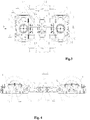
- a bogie suspension traction device of a low floor articulated rail vehicle is shown in Fig.1 , which is provided on a low floor articulated rail vehicle.
- the rail vehicle includes multiple carriages, a bogie 1 is installed below each junction of every two carriages and two carriages are respectively connected to the bogie 1 through a rotary mechanism 101.
- the bogie 1 includes a frame 2, a suspension traction device 3, a wheel-set 4, a drive motor (not shown) and a brake and so on.
- Four drive motors are provided to respectively drive four wheels 5.
- the four drive motors and the brakes are fixedly mounted on the mounting beams 81 on both sides of the frame 2, respectively.
- the drive motors and the brakes are mounted on the outside of the wheel 5, beneficial to reducing the height of the floor.
- the frame 2 comprises two side beams 80 and two end beams 82.
- a central cross beam 77 is provided in the middle of the two side beams 80.
- the two end beams 82 are arranged in parallel and symmetrically on both sides along the longitudinal direction of the central cross beam 77 (in the longitudinal direction of the vehicle body).
- the two side beams 80, the two end beams 82 and the central cross beam 77 form a frame structure shaped in a Chinese character as " "”.
- the outer sides of the side beam 80 are provided with mounting beams 81 for mounting drive motors and brakes in the transverse direction (referred to as the width direction of the vehicle body).
- the central cross beam 77 is integrally cast and shaped, and both ends of the center beam 77 are welded to lateral plates of the two side beams 80.
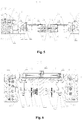
- the suspension traction device 3 comprises swing bolster mechanisms 6, traction rod mechanisms 7, primary spring (not shown), secondary spring mechanisms 8, transverse dampers 9 and vertical dampers 10 and the like.
- Two groups of swing bolster mechanisms 6 and two groups of traction rod mechanisms 7 are provided.
- the structures of the two groups of swing bolster mechanisms 6 are identical, and are respectively installed in the middle of the two wheels 5 in each group of wheel-set 4.
- the two groups of swing bolster mechanisms 6 are connected to the vehicle bodies of the adjacent two carriages by the rotary mechanism 101, respectively.
- the vehicle's small curving performance is greatly improved and the height of the floor surface is significantly reduced, conducive to the installation of getting on and off the vehicle.
- the driving performance of the vehicle is also greatly improved, helpful to reduce the wear of wheel and track. And the number of bogies 1 arranged in the vehicle group is reduced, thus costs of vehicle manufacturing, maintenance and repair are saved.
- Each group of swing bolster mechanisms 6 is connected with a frame 2 through a set of traction rod mechanism 7, two sets of secondary spring mechanisms 8 are provided between the end beams 82 of the frame 2, below each set of swing bolster mechanism 6.
- a transverse damper 9 and two vertical dampers 10 are mounted on a side, facing the outer side of the frame 2, of each set of swing bolster mechanism 6.
- Two vertical dampers 10 are provided on both sides, in the transverse direction of the vehicle body, of the transverse damper 9.
- the bogie 1 comprises four vertical dampers 10 and two transverse dampers 9, to reduce the vibration of the vehicle body in the transverse and vertical direction and improve the ride comfort.
- each group of swing bolster mechanism 6 is connected with the central cross beam 77 of a frame 2 through a set of traction rod mechanisms 7.
- Two sets of traction rod mechanisms 7 are provided between the two side beams 80 and are set separately on two sides of the central cross beam 77.
- Each set of traction rod mechanism 7 comprises one or more traction rods 16, that is, each group of swing bolster mechanism 6 is connected with a central cross beam 77 of a frame 2 through one or more traction rods 16.
- One end of the traction rod 16 is connected with the swing bolster mechanism 6, and the other end is connected with the central cross beam 77 of the frame 2.
- Two groups of swing bolster mechanism 6 and two sets of traction rod mechanism 7 are as a whole arranged as a flat structure, further reducing the height of the floor.
- each set of traction rod mechanism 7 comprises two traction rods 16, that is, each group of swing bolster mechanism 6 is connected with the central cross beam 77 of the frame 2 through two traction rods 16.
- the two traction rods 16 are arranged parallel to each other between the two side beams 80 of the frame 2.
- Two groups of swing bolster mechanism 6 are respectively connected with a central cross beam 77 of a frame 2 through two traction rods 16, thus it better realizes the transmission of the traction and braking force and bears the vertical, horizontal and longitudinal loads, while vehicle is running. Ends of each traction rod 16 are directly connected to the central cross beam 77 of the frame 2, so that two groups of swing bolster mechanism 6 and two sets of traction rod mechanism 7 do not affect each other.
- the longitudinal movement of one swing bolster mechanism 6 does not affect the movement in the longitudinal direction of another swing bolster mechanism 6, and the vibration of one carriage is not passed to another carriage.
- the two adjacent vehicle bodies are decoupled, and improves the ride comfort and the reliability during operation.
- parallel to each other and The two traction rods 16 which is parallel to each other serve as anti-side roll bars in the structure that each group of swing bolster mechanism 6 is connected with a central cross beam 77 of a frame 2 through two traction rods 16, so that the vehicle runs more smoothly and the structure of the bogie is simplified.
- the traction rod 16 includes a rod 16a arranged in the middle and spherical joints 16b arranged at both ends. Both ends of the rod 16a are U-shaped, and the two spherical joints 16b are respectively inserted into the U-shaped structure and fixedly connected to the rod 16a by fasteners.
- the spherical joint 16b is composed of a spherical joint axis in the center and a spherical joint sleeve outside.
- the spherical joint axis and the spherical joint sleeve are hinged and fitted through a spherical surface, and the spherical joint sleeve is connected to the rod 16a.
- a connecting seat 16c is mounted on each of the two spherical joint axis of each spherical joint 16b and the two connecting seats 16c are symmetrically provided on both sides of the spherical joint 16b, and the connecting seat 16c is a cylindrical rubber material.
- a mounting hole (not shown) is provided in the center of the connecting seat, and is fitted and fixed to the spherical joint axis of spherical joint 16b.
- each group of swing bolster mechanism 6 comprises a swing bolster 11 and the swing bolster 11 is a polygon.
- the swing bolster 11 is made by whole casting, not only to ensure its overall strength and stiffness, to avoid the welding stress of the welding structure and to increase the load capacity of the swing bolster 11 substantially, but also to reduce the thickness and the weight of the swing bolster 11 and the height of the floor surface, and the vehicle can be reduced in weight meanwhile.
- a mounting interface of first traction rod 12 which is connected to the traction rod 16 is provided on a side of the swing bolster 11 facing to the central cross beam 77. The mounting interface of first traction rod 12 and the swing bolster 11 are integrally casted.
- the number of the mounting interface of first traction rods 12 depends on the number of traction rods 16.
- two traction rods 16 are mounted on a side of each swing bolster 11.
- the ends of each traction rod 16 are provided with two mounting interface of first traction rods 12, for fixing the two connecting seats 16c of the ends of the traction rod 16. So that four mounting interface of first traction rods 12 are provided on one side of each swing bolster 11.
- the four mounting interface of first traction rods 12 are arranged side by side in a line on one side of the swing bolster 11 and two of the four mounting interface of first traction rods 12 in the middle close together or are as a whole structure.
- Each of the upper surfaces of the four mounting interface of first traction rods 12 has an arc portion curving downward, in order to reduce the installation height of the traction rod mechanisms 7 as a whole and then reduce the height of the floor.
- Each mounting interface of first traction rod 12 has a circular first mounting opening 17 for accommodating the connecting seat 16c of the end of the traction rod 16.
- the spherical joint 16b of the end of the traction rod 16 is set between two mounting interface of first traction rods 12 and four bolt holes for fixing bolts 18 are provided on two sides of each mounting interface of first traction rod 12.
- the four mounting interface of first traction rods 12 are all set as separate structures, that is, being separated as a upper and lower part.
- a semicircular opening is respectively provided on the upper and lower part.
- the upper and the lower part after being buckled together, form the circular first mounting opening 17.
- the upper and the lower part are correspondingly provided with bolt holes for fixing bolts 18, the connecting seat 16c of the end of the traction rod 16 is tightly fixed in the first mounting opening 17 after the upper and the lower part of the mounting interface of first traction rods 12 are buckled together, and finally the upper and lower parts are fixed together by four bolts 18 to achieve a fixed mounting of the traction rod 16.
- the upper part of the mounting interface of first traction rod 12 is integrally formed with the swing bolster 11 and the lower part is separately mounted.
- the lower part of the mounting interface of first traction rod 12 is integrally formed with the swing bolster 11 and the upper part is separately mounted.
- a pin hole 78 is provided on the outer circumference of each connecting seat 16c.
- the upper or the lower part of mounting interface of first traction rod 12 is correspondingly provided with a pin hole.
- a locating pin 79 is provided through the pin hole 78 of the connecting seat 16c during installation, fitted with the pin hole of the mounting interface of first traction rod 12, so that the traction rod 16 is accurately mounted and the mounting efficiency is improved.
- a mounting plate 41 is provided above the mounting interface of first traction rod 12, and every two adjacent bolts 18 are provided with amounting plate 41 correspondingly.
- the mounting plate 41 is a step-like structure and two bolt holes are provided in the lower step for fixing the mounting plate 41 to the mounting interface of first traction rod 12 through the bolts 43.
- Two bolt holes (not shown) are provided in the upper step, and the two bolt holes respectively correspond to and communicate with the bolt holes of mounting interface of first traction rod 12 below.
- the bolt 18 simultaneously passes through the bolt holes of the mounting interface of first traction rod 12 and the bolt holes in the upper step of the mounting plate 41, and the upper and lower parts of the mounting interface of first traction rod 12 are fixed and connected together.
- the rotary mechanism 101 comprises a slewing bearing 14 and a connecting seat of vehicle body 19.
- the center of the upper surface of the swing bolster 11 is a recessed accommodating cavity 13 in which the slewing bearing 14 is mounted.
- the slewing bearing 14 is fixedly connected to the swing bolster 11 on the circumference by a plurality of bolts 15.
- the accommodating cavity 13 protects the slewing bearing 14 and increases the carrying capacity of the slewing bearing 14.
- Penetrated bolt holes 38 are provided on the circumference of the swing bolster 11, and the bolt hole 38 is a countersunk hole.
- a plurality of bolts 15 are correspondingly inserted through the bolt holes 38 from the bottom and are fixedly connected to the slewing bearing 14.
- the head of the bolt 15 is mounted inside the countersunk hole, in order to facilitate the installation and to prevent the head of the bolt 15 from protruding to the outside of the swing bolster 11.
- the connecting seat of vehicle body 19 is a disc-like structure
- the center of the connecting seat of vehicle body 19 is a through-opening 20
- the through-opening 20 is raised upwardly to form an annular boss 24.
- the annular boss 24 is inserted into an underframe 23 of the vehicle body during installation, conducive to installation and positioning.
- the periphery of the through-opening 20 is provided with an inner and an outer loop of bolts. Twelve inner loop of bolts 21 are provided and are fixedly connected with the underframe 23 of the vehicle body. Twenty-four outer loop of bolts 22 are provided and are fixedly connected with the slewing bearing 14 and are fixedly connected with the underframe 23 of the vehicle body at the same time.
- a loop of annular mounting tables 25 projecting downwardly are provided on periphery of through-opening 20 of the lower surface of the connecting seat of vehicle body 19, and the annular mounting table 25 is pressed to the inside of slewing bearing 14 to be fixed during installation.
- the lower half of the outer circumferential surface of the annular mounting table 25 is a tapered surface inclined in the center direction, playing a better guide during the installation and being conducive to the installation.
- the connecting seat of vehicle body 19 is machined integrally, the overall structure is simple, easy to process and also conducive to the installation.
- the swing bolster 11 is connected to the underframe 23 of the vehicle body via the slewing bearing 14.
- the slewing bearing 14 carries the vertical, longitudinal and lateral loads, and the slewing bearing 14 is able to rotate in 360 degrees, so that the ground vehicle meets requirements of going through small curve (such as 25m) and the vehicle's small curving performance is improved.
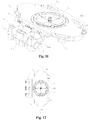
- the swing bolster 11 is provided with an oiling mechanism 26, for filling oil for the slewing bearing 14 to ensure that the slewing bearing 14 works normally.
- the oiling mechanism 26 comprises a group of grease nipples 27.
- four grease nipples 27 are provided in order to ensure the effect of oiling and the lubricating oil is distributed evenly over the slewing bearing 14.
- the four grease nipples 27 are respectively connected with four oiling pipes 28, the ends of the four oiling pipes 28 are respectively provided with a strait union 40, and the oiling pipe 28 is connected with the slewing bearing 14 through the strait union 40.
- the four grease nipples 27 are mounted on a mounting seat of grease nipple 29, the mounting seat of grease nipple 29 is integrally molded with a highly wear-resistant nylon material and is mounted directly in the center of the accommodating cavity 13 of the swing bolster 11, i.e., the four grease nipples 27 is mounted at the center of the slewing bearing 14.
- Four notches are provided on the annular mounting table 25 of the connecting seat of vehicle body 19, which is used for keeping away from the four oiling pipes 28 when the annular mounting table 25 is pressed into the inside of the slewing bearing 14.
- the four grease nipples 27 are self-sealing grease nipples and are provided with an elastic component inside.
- the mounting seat of grease nipple 29 is a cylindrical structure as a whole and the bottom of the cylinder is placed on the swing bolster 11.
- Four vertical accommodating cavities 30 extend in the vertical direction are provided on the circumferential circle of the cylinder, which are approximately semicircular and are recessed.
- the four grease nipples 27 are respectively mounted in the four vertical accommodating cavities 30.
- the vertical accommodating cavity 30 not only acts as a support for the grease nipple 27 mounted therein, but also serves to protect the grease nipple 27 during the movement of the vehicle.
- first lateral accommodating cavities 32 extending laterally around the outer circumference of the cylinder are also provided.
- the four oiling pipes 28 are connected to the bottom of the four grease nipples 27 through pipe joints, respectively. As shown in Fig. 14 , the four oiling pipes 28 are firmly fixed to the mounting seat of grease nipple 29 by the ribbon 33, and the ribbon 33 is tied to the first lateral accommodating cavity 32.
- the ribbon 33 not only effectively prevents breaking off between the oiling pipe 28 and the grease nipple 27 during the operation of the vehicle, but also facilitates the disassembly.
- Second lateral accommodating cavities 98 extending laterally around the outer circumference of the cylinder are further provided, and the second lateral accommodating cavity 98 is set below the first lateral accommodating cavity 32.
- the oiling pipe 28 is bent toward the outside at the bottom and the second lateral accommodating cavity 98 is provided to facilitate the bending of the oiling pipe 28 and also to protect the oiling pipe 28. Since the oiling pipe 28 is a copper pipe, the oiling pipe 28 can support the grease nipple 27 above by its own strength. The grease nipple 27 is fixed by tightening the oiling pipe 28 with the ribbon 33, and the mounting structure is simple and convenient.
- a movable top cover 102 is mounted on the vehicle body underframe corresponding to the space above the through-opening 20 in the center of the connecting seat of vehicle body 19.
- the top cover 102 is opened to expose the grease nipple 27 below, and the top cover 102 is covered after the oiling is completed.
- the slewing bearing 14 be oiled at any time, but it is also simple and convenient for routine maintenance.
- two recessed cavities 34 are provided on two corners in the upper surface of the swing bolster 11.
- the recessed cavity 34 works as a reinforcing rib to enhance the structural strength and stiffness of the swing bolster 11.
- a drain port 35 is respectively provided in each of the two recessed cavities 34, and the drain port 35 penetrates through the swing bolster 11, to facilitate the discharge of the rainwater and the flushing water stored in the recessed cavity 34.
- the outside of the four centrally converging sides of the swing bolster 11 are respectively provided with first reinforcing ribs 36 protruding outwards.
- two damper mounting seats 37 extending downward are arranged at the edge to the outside of the frame 2.
- the transverse dampers 9 and vertical dampers 10 are fixedly mounted on the damper mounting seats 37 via bolts 90.
- Two damper mounting seats 37 are set side by side, one is applied to fix a transverse damper 9 and a vertical damper 10, and the other one is used to fix another vertical damper 10.
- the first reinforcing rib 36 and the damper mounting seat 37 are integrally formed with the swing bolster 11, and are transited with the swing bolster 11 through arcs.
- the first reinforcing rib 36 and the damper mounting seat 37 further improves the structural strength and stiffness of the swing bolster 11.
- a protruding part 45 is projected downward at a central position of the lower surface of the swing bolster 11 and the protruding part 45 is integrally formed with the swing bolster 11 or the two parts are welded together.
- the end beam 82 of the frame 2 is provided with an opening 46 for the protruding part 45 to insert, corresponding to the protruding part 45.
- the opening 46 is a rectangular structure, and the length in the transverse direction of the vehicle body is larger than the length in the longitudinal direction of the vehicle body.
- An opening 46 is provided on each of the two end beams 82, in regard to the two swing bolsters 11.
- two transverse backstops 47 are mounted on the side walls of the two transverse sides of each opening 46.
- the two transverse backstops 47 protrude from both sides towards the protruding part 45 below the swing bolster 11.
- the protruding part 45 below the swing bolster 11 extends to the space between the two transverse backstops 47.
- a transverse stop gap is left between the protruding part 45 and each transverse backstop 47.
- the transverse backstop play a better role in the horizontal stop in the operating process of the vehicle, thus to limit the lateral displacement of the vehicle beyond normal degrees of freedom, in order to avoid dangerous conditions such as the rollover when the vehicle goes through small radius of curve.
- the transverse backstop 47 is composed of three layers, namely, a wear-resisting layer 47a, a rubber layer 47b and a bottom layer.
- the wear-resisting layer 47a is located on the top layer which is in contact with the protruding part 45 of the swing bolster 11.
- the transverse backstop 47 is in contact with the protruding part 45 of the swing bolster 11 via the wear-resisting layer 47a.
- the wear-resisting layer 47a is made of a nylon material with high abrasion resistance characteristics. The abrasion resistance characteristics of the nylon material improve the service life of the transverse backstop 47.
- the rubber layer 47b is provided between the wear-resisting layer 47a and the bottom layer, the rubber layer 47b is integrally molded by vulcanization with the bottom layer, and the wear-resisting layer 47a and the rubber layer 47b are bonded together by glue.
- the bottom layer is secured to the side wall of the opening 46 in the end beam 82 by bolts 48.
- the bottom layer is composed of three parts, and they are a first bottom plate 47c, a second bottom plate 47d and a third bottom plate 47e, respectively.
- the first bottom plate 47c is located at the bottom of the bottom layer and an opening is at the center of the first bottom plate 47c, and the cylindrical second bottom plate 47d with a thicker thickness is welded to the opening.
- the second bottom plate 47d extends into the inside of the rubber layer 47b and an inner tapping hole 47f is provided in the center of the second bottom plate 47d.
- the inner tapping hole 47f penetrates the second bottom plate 47d and the third bottom plate 47e is fixed to the top of the inner tapping hole 47f, thus the structure plays a role of a backstop while ensuring the strength of the joint.
- the first bottom plate 47c, the second bottom plate 47d and the third bottom plate 47e and the rubber layer 47b are integrally vulcanized and formed.
- the inner tapping hole 47f could be a notch structure that does not penetrate through the second bottom plate 47d and it is not necessary to separately provide the third bottom plate 47e in this situation.
- a mounting hole 50 is formed in the side wall of the end beam 82.
- a bolt 48 passes through the mounting hole 50 of the end beam 82 and is fixedly connected with the inner tapping hole 47f of the bottom layer of the transverse backstop 47, then the transverse backstop 47 is fixed to the end beam 82.
- a fixed washer (not shown in figures) is mounted between the mounting hole 50 in the side wall of the end beam 82 and the head of the bolt 48.
- the transverse backstop 47 ensures a good stiffness curve performance under the requirements of the elasticity, and ensures that the lateral displacement of the transverse backstop 47 is minimized in the worst operating conditions.
- the shaking caused by the traverse movement of the vehicle is greatly reduced, the running smoothness is improved and the ride comfort is increased.
- the structure is simple, the performance is reliable and the durability is strong.
- transverse backstop 47 When the transverse backstop 47 is mounted, it is necessary to adjust the transverse stop gap between the top of the transverse backstop 47 and the protruding part 45 of the swing bolster 11.
- One or more adjusting shims 49 are further provided between the first bottom plate 47c of the transverse backstop 47 and the side walls of the end beam 82, and the adjustment is convenient and fast.
- a longitudinal backstop 42 extends, from each of the two side walls in the longitudinal direction inside the opening 46, to the protruding part 45.
- the longitudinal backstop 42 functions as a longitudinal bearing, and the longitudinal backstop 42 engages with the protruding part 45 to drive the vehicle to operate when the traction rod 16 fails to work.
- a lifting device is provided between the swing bolster 11 and the end beam 82 of the frame 2 to limit the maximum vertical vibration distance of the vehicle body so as to avoid overshooting.
- the lifting device not only limits the maximum vertical vibration distance of the vehicle body, but also plays a role of the overall lifting of the bogie.
- the lifting device is two lifting rods 51 which are mounted on the lower surface of the swing bolster 11.
- the two lifting rods 51 are arranged symmetrically on two lateral sides of the protruding part 45, to ensure the connection strength and to maintain the balance when lifting.
- the structures of the two lifting rods 51 are the same, the top end of the lifting rod 51 is connected to the swing bolster 11, and the bottom end of the lifting rod 51 is connected to the end beam 82 of the frame 2.
- the main body of the lifting rod 51 is a long cylinder
- the top end of the lifting rod 51 is a T-shaped head
- the two sides of the T-shaped head are stop planes 57.
- the bottom of the lifting rod 51 has an external thread and the upper portion of the external thread is a stop portion 61 with a slightly larger diameter.
- a fixing port 52 is designed in the lower surface of swing bolster 11 where the lifting rod 51 is to be mounted.
- a backing plate 53 is provided inside the fixing port 52, i.e., above the top end of the lifting rod 51.
- An anti-loosing backing plate 54 is mounted on the outer circumference of the fixing port 52.
- the inner circle of the anti-loosing backing plate 54 is two straight lines opposed to the stop plane 57 of the lifting rod 51, for restricting the rotation of the lifting rod 51.
- a mounting block 55 is further provided below the anti-loosing backing plate 54, and the inner circle of the mounting block 55 is a tapered surface which cooperates with the bottom surface of the T-shaped head of the lifting rod 51.
- the bottom of the outer circle of the mounting block 55 is designed with a step-like structure and four bolt holes are provided in the step-like structure.
- the mounting block 55 and the swing bolster 11 are fixed together via four bolts 56.
- the T-shaped head of the lifting rod 51 is fixed by the mounting block 55 after installation.
- the mounting block 55 is also provided with a recessed annular groove which is filled with a sealing ring 58 therein, thus to further seal and fix the whole structure.
- a lifting opening 59 is provided for each lifting rod 51 on the end beam 82 of the frame 2 and the lifting opening 59 is symmetrically set on both sides of the opening 46.
- a bayonet 60 is provided at the bottom of the lifting rod 51 and the diameter of the bayonet 60 is greater than the diameter of the lifting opening 59.
- the bayonet 60 is away from the lifting opening 59 with a vertical distance and the distance is the maximum vertical vibration distance allowed.
- the inner surface of the bottom of the bayonet 60 is a tapered surface and a locating block 62 is mounted below the bayonet 60.
- the upper surface of the locating block 62 is a tapered surface cooperating with the tapered surface of the bayonet 60.
- the inner circle of the locating block 62 is designed with a step-like structure and the step-like structure is abutted against the stop portion 61 of the lifting rod 51 after installation, to play a role of locating and stopping.
- a nut 63 is tightened on the bottom of the lifting rod 51 below the locating block 62 for fixation.
- the inner circle of the bayonet 60 has a recessed annular groove which is provided with an O-shaped sealing ring 64 therein, for fixation and sealing.
- the end beam 82 at the lifting opening 59 is provided with an upward-concaving portion 65 in order to protect the lifting rod 51.
- the mounting hole 50 for mounting the bolt 48 of the transverse backstop 47 is arranged on the side wall of the upward-concaving portion 65 and the lifting opening 59 is arranged on the top wall of the upward-concaving portion 65.
- the upward-concaving portion 65 not only facilitates the installation of the transverse backstop 47 and the lifting rod 51 conveniently, but also facilitates routine maintenance. Additional structures such as transverse backstop mounting seats and vertical backstop mounting seats are not needed, so that the structure of the bogie 1 is simplified to a certain extent and the weight of the bogie 1 is also reduced.
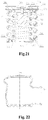
- the secondary spring mechanism 8 is composed of an upper backing plate 66, a lower backing plate 67 and a spring in the middle.
- the spring in the middle is a steel double-round spring and is composed of an inner spring 68 and an outer spring 69.
- the upper backing plate 66 is composed of an upper metal plate 66a, a lower metal plate 66b and a rubber layer 66c in the middle.
- the rubber layer 66c is vulcanized together with the upper metal plate 66a and the lower metal plate 66b and the upper backing plate 66 is provided with a central hole 66d.
- a first mounting groove 70 is provided on the lower surface of the swing bolster 11 corresponding to the upper backing plate 66.
- An annular mounting portion 71 protruding downwards is provided at the center of the first mounting groove 70, and the mounting portion 71 matches with the center hole 66d and is inserted into the center hole 66d, for positioning and fixation.
- the diameter of the first mounting groove 70 matches with the upper backing plate 66, so that the upper backing plate 66 is caught in the first mounting groove 70 and is fixed. Meanwhile, the center hole 66d is caught in the mounting portion 71, thereby the upper backing plate 66 and the swing bolster 11 are fixedly connected. There is no need for a conventional bolt connection between the upper backing plate 66 and the swing bolster 11, thus, to make the mounting and dismounting easier and more convenient, to reduce the use and maintenance of fasteners and to make the structure of the secondary springs 8 more compact, so that the device is more suitable for low-floor urban rail vehicles with limited space between the vehicle body and bogie.
- the lower surface of the lower metal plate 66b of the upper backing plate 66 bulges downwards to form an upper spring locating protrusion 66e which is ring-shaped.
- the upper spring locating protrusion 66e is located between the inner spring 68 and the outer spring 69.
- the upper spring locating protrusion 66e is a metal plate and is welded together or integrally molded with the lower metal plate 66b.
- a second mounting groove 72 corresponding to each secondary spring mechanism 8 is provided on the end beam 82 of the frame 2.
- the diameter of the second mounting groove 72 matches with the lower backing plate 67, so that the lower backing plate 67 is caught in the second mounting groove 72 and is fixed.
- the lower backing plate 67 is composed of a locating seat 67a and an adjusting pad, and the locating seat 67a is a metal plate.
- the upper surface of the locating seat 67a bugles upwards to form a lower spring locating protrusion 67b which is ring-shaped.
- the spring locating protrusion 67b is located between the inner spring 68 and the outer spring 69.
- the spring locating protrusion 67b is a metal plate and is welded together or integrally molded with the locating seat 67a. After installation, the lower backing plate 67 is secured to the bottom of the second mounting groove 72 of the frame 2 and the secondary spring mechanism 8 and the end beam 82 are fixedly connected. There is no need for a conventional bolt connection between lower backing plate 67 and the end beam 82, to make the mounting and dismounting easier and more convenient, thus, to reduce the use and maintenance of fasteners and to make the structure of the secondary spring 8 more compact.
- the second mounting groove 72 of the end beam 82 is an inverted conical structure. While the secondary spring 8 is fixed, it also prevents the secondary spring 8 from colliding with the inner wall of the second mounting groove 72 when the vehicle is running. In the embodiment, the second mounting groove 72 is a sinking structure, and the height of the floor surface is further reduced.
- the upper spring locating protrusion 66e and the lower spring locating protrusion 67b act as a damper, and on the other hand, this "protrusion" structure separates the inner spring 68 and the outer spring 69.
- the possibility of collision between the inner spring 68 and the outer spring 69 is lowered, thus, it effectively prevents the instability of the secondary spring 8.
- the adjustment pad of the lower backing plate 67 has two different structures. One is an inner spring adjusting pad 67c, the inner spring adjusting pad 67c is a rubber pad and is mounted against the inner ring of lower spring locating protrusion 67b which is the bottom of the inner spring 68, for adjusting the inner spring 68 at a predetermined load compression height. The other one is an outer spring adjusting pad 67d.
- the outer spring adjusting pad 67d is a rubber pad and is mounted against the outer ring of lower spring locating protrusion 67b which is the bottom of the outer spring 69, for adjusting the outer spring 69, to ensure the height of the inner spring 68 and the outer spring 69 compressed at the same working load, thereby to ensure the smooth operation between the vehicle body and the bogie.
- the upper backing plate 66 uses the flexibility of the rubber layer 66c to greatly reduce the vibration and the impact caused by the steel spring.
- a cylindrical protective cover 73 is mounted between the first mounting groove 70 and the second mounting groove 72.
- the secondary spring mechanism 8 is enclosed within the protective cover 73.
- the protective cover 73 is preferably vulcanized and made of a rubber which has an excellent oil resistance and corrosion resistance.
- the protective cover 73 is composed of an upper engaging portion, an intermediate cylindrical portion and a lower engaging portion, and the intermediate cylindrical portion is a wavy structure.
- the upper engaging portion and the lower engaging portion are respectively sealed and fixedly connected to the first mounting groove 70 and the second mounting groove 72. It not only facilitates the installation and removal of the protective cover 73, but also makes the secondary spring mechanism 8 sealed into the protective cover 73 to prevent oil, water droplets, etc. from penetrating into the frame and causing corrosion.
- the dustproof structure has the foldable characteristics with a "wave" shape itself, so as to seal with different spring deformations under different loads.
- a vertical backstop 74 is provided at the center of the inner spring 68.
- the vertical backstop 74 is fixed to the upper backing plate 66 of the secondary spring mechanism.
- the vertical backstop 74 is composed of a rubber 74a, a bottom plate 74b and a stopper plate 74c.
- the rubber 74a, the bottom plate 74b and the stopper plate 74c are vulcanized together, the rubber 74a is set below the bottom plate 74b and the center of the bottom plate 74b has an internal screw hole (not shown).
- the stopper plate 74c is set at the bottom of the internal screw hole.
- the bottom plate 74b and the stopper plate 74c are metal plates.
- the vertical backstop 74 cooperates with a boss 76 and act as a safety support, to ensure the travel safety of the rail vehicle, even if a secondary spring is broken.
- the lower metal plate 66b of the upper backing plate 66 of the secondary spring mechanism 8 has a mounting hole in the center.
- the bottom plate 74b and the lower metal plate 66b are fixedly connected together by bolts 75.
- An adjusting plate 74d is also provided between the bottom plate 74b and upper backing plate 66, for adjusting the vertical stop gap between the bottom of the vertical backstop 74 and the top of the boss 76 during installation.
- a boss 76 bulging upwards is arranged, which is integrally cast with the frame 2.
- An opening is provided at the center of the lower backing plate 67 of the secondary spring mechanism 8, and the boss 76 is inserted in the opening of the lower backing plate 67 after installation, which extends into the inside of the inner spring 68 and faces right to the vertical backstop 74.
- a vertical stop gap is provided between the bottom of the vertical backstop 74 and the top of the boss 76. The bottom of the vertical backstop 74 is not in contact with the top of the boss 76 when the vehicle is normally operating.
- the structure acts as a stopper and plays a role of changing the stiffness at the same time, which is beneficial to improve the dynamic performance of the operation of the vehicle.
- the central cross beam 77 of the frame 2 is provided with an elongated annular groove 83 which extends laterally.
- the upper and lower surfaces of the central cross beam 77 are respectively provided one annular groove 83.
- the intermediate connection of the central cross beam 77 increases the structural strength and the capacity of carrying load.
- the two elongated annular grooves 83 are alternative to be arranged through the upper and lower surfaces.
- a mounting interface of second traction rod 84 is mounted on both side walls of the annular groove 83 of the central cross beam 77 and four mounting interfaces of second traction rod 84 are mounted on each side wall.
- the four mounting interfaces of second traction rod 84 are arranged side by side on one side wall of the annular groove 83.
- Two mounting interfaces of second traction rod84 in the middle are close to each other and fixed, or are set as an integral structure.
- the four mounting interfaces of second traction rod 84 are used for fixing four connecting seats 16c on the ends of the two traction rods 16. That the annular groove 83 is provided in the central cross beam 77 greatly facilitates the disassembly of the mounting interface of second traction rod 84.
- the mounting interface of second traction rod 84 is designed as a separate structure, which is divided into a left part and a right part. Each part has a semicircular mounting opening and the two parts are engaged to form a complete second mounting opening 39, for accommodating the connecting seat 16c at the end of the traction rod 16.
- One part is fixedly connected to the side wall of the central cross beam 77 and the center of the part of the mounting interface of second traction rod 84 is a smooth through hole. Accordingly, a threaded hole with an internal thread is also provided on the side wall of the central cross beam 77.
- the part of the mounting interface of second traction rod 84 and the central cross beam 77 are fixed together by bolts 85.
- a groove 103 is provided on the inner wall of the part of the mounting interface of second traction rod 84 for accommodating the head of the bolt 85, in order to prevent the bolts 85 from affecting the installation of the traction rod 16 after installation.
- the two connecting seats 16c at the ends of the traction rod 16 are placed in a semicircular mounting opening on both sides, the other part of the mounting interface of second traction rod is engaged and the two parts are fixedly connected together by bolts 86, and then the connecting seats 16c at the ends of the traction rod 16 are fixed.
- the nut 104 for tightening the end of the bolt 86 extends from the center of the annular groove 83, is inserted to the tail of the bolt 86, and is tightened.
- the upper and lower annular grooves 83 are respectively provided with two nuts 104 to completely fix the traction rod 16. It is easy to operate and the installation efficiency is greatly improved.
- the locating pin 79 is mounted in the pin hole 78 of the connecting seat 16c in the same manner as the mounting interface of first traction rod 12 is mounted. The locating pin 79 cooperates with the pin hole on the mounting interface of second traction rod 84, so that the traction rod 16 is accurately mounted and the installation efficiency is greatly improved.
- a connecting seat 16c of a cylinder is provided at the end of the traction rod 16, which cooperates with the first mounting opening 17 of mounting interface of first traction rod 12 and the second mounting opening 39 of the mounting interface of second traction rod 84 to fix.
- Longitudinal transmission force is transmitted through a complete circular fit surface. It not only improves the vertical transmission capacity, but also reduces abrasion.
- both ends of the traction rod 16 are provided with spherical joints so as to have a smaller lateral rigidity. Thus, it meets the larger lateral displacement and longitudinal displacement between the vehicle body and the bogie, and it improves the longitudinal traction capability and the anti-roll capability and improves the overall performance.
- a transverse damper 9 and two vertical dampers 10 are mounted on the damper mounting seat 37 outside each swing bolster 11, and two vertical dampers 10 and the transverse damper 9 are arranged on both sides of the vehicle body in the transverse direction.
- Two damper mounting seats 37 are provided, one transverse damper 9 and one vertical damper 10 are mounted on one of the damper mounting seats 37, and one vertical damper 10 is mounted on the other damper mounting seat 37.
- the other ends of the transverse damper 9 and the vertical dampers 10 are fixedly connected to the end beam 82 of the frame 2.
- the structure of the transverse damper 9 and the vertical damper 10 are the same and are composed of a damper body 87, a first connecting rod 88 and a second connecting rod 89.
- the housing of the damper body 87 is provided with four mounting holes which are respectively fixed to damper mounting seat 37 of the swing bolster 11 by bolts 90.
- One end of first connecting rod 88 is fixedly connected to the damper body 87 and the other end is connected to the second connecting rod 89.
- the other end of the second connecting rod 89 is connected to the frame 2.
- a transverse damper mounting seat 100 and a vertical damper mounting seat 99 are provided on the side wall of the end beam 82.
- the other end of the second connecting rod 89 is connected to the transverse damper mounting seat 100 or the vertical damper mounting seat 99 of the end beam 82.
- the ends of the second connecting rod 89 are connected to the first connecting rod 88, the transverse damper mounting seat 100 or the vertical damper mounting seat 99 by a joint bearing 91.
- the outer ring of the joint bearing 91 is connected to the second connecting rod 89, and the inner ring of the joint bearing 91 is connected to a connecting shaft 92.
- the connecting shaft 92 extends from one side and sticks into the transverse damper mounting seat 100 or the vertical damper mounting seat 99 of the frame 2 and is fixed by bolts which tightens from the top.
- the connection structure between the second connecting rod 89 and the first connecting rod 88 is the same as the structure mentioned prior.
- the second connecting rod 89 is divided into two sections and the two sections are connected by a connecting rod 105 in the middle.
- the connecting rod 105 and the two sections of the second connecting rod 89 are connected by screws. This structure facilitates the fixed connection of the second connecting rod 89 with the first connecting rods 88, the transverse damper mounting seat 100 or the vertical damper mounting seat 99 at both ends.
- a dust cover 93 is provided respectively on each outer side of the joint bearing 91 at both ends of the second connecting rod 89.
- the dust cover 93 is made of a rubber material and has two openings which are an opening 94 and an opening 95. The angle between the orientations of the opening 94 and the opening 95 is 90 degrees.
- the opening 94 is used to overlap the second connecting rod 89 and the opening 95 is used to overlap the connecting shaft 92 which is connected to the second connecting rod 89.
- the diameter of the opening 95 is slightly smaller than the diameter of the connecting shaft 92 and its round edge is tapered, so that it is tightly sealed after installation.
- the opening 94 is slightly larger in diameter, easy to install.
- the first connecting rod 88 of the transverse damper 9 is set vertically.
- the second connecting rod 89 is provided laterally, the first connecting rod 88 of the vertical damper 10 is provided laterally and the second connecting rod 89 is provided vertically. Since the joints are connected by means of joint bearings 91, the second connecting rod 89 swings in a certain degree in the lateral or vertical direction when the vehicle is subjected to lateral or vertical vibration, thereby the first connecting rod 88 is driven to swing.
- the damper body 87 restricts the swing angle of the first connecting rod 88 and further plays a damping effect in the lateral and vertical direction.
- the transverse damper 9 and the vertical damper 10 are mounted between the side walls of the swing bolster 11 and the sides of the end beam 82 of the frame 2, the damper body 87 is connected with the frame 2 which acts as a vibration source through the first connecting rod 88 and the second connecting rod 89.
- the rotational motion of the damper body 87 is converted into the linear motion of the second connecting rod 89, the lateral and vertical displacement magnification is effectively achieved and the damping effect of the damper is increased.
- the adjustment is more flexible, the structure of the bogie is more simple and compact, and it is more conducive to reduce the height of the floor.
Landscapes
- Engineering & Computer Science (AREA)
- Mechanical Engineering (AREA)
- Vehicle Body Suspensions (AREA)
Claims (15)
- Drehgestell (1) für ein Niederflur-Gelenkschienenfahrzeug, umfassend:einen Rahmen (2); undeine Aufhängezugvorrichtung (3), die einen Wiegenmechanismus (6), einen Zugstangenmechanismus (7), einen primären Federmechanismus und einen sekundären Federmechanismus (8) umfasst;wobei der sekundäre Federmechanismus (8) zwischen dem Wiegenmechanismus (6) und dem Rahmen (2) des Drehgestells (1) angeordnet ist,wobei zwei Gruppen der Wiegenmechanismen (6) und zwei Sätze der Zugstangenmechanismen (7) vorgesehen sind,wobei zwei Gruppen von Wiegenmechanismen (6) jeweils in der Mitte von zwei Gruppen von Radsätzen (4) vorgesehen sind, undwobei jede Gruppe des Wiegenmechanismus (6) mit dem Rahmen (2) über einen Satz des Zugstangenmechanismus (7) verbunden ist, und jede Gruppe des Wiegenmechanismus (6) mit einem Wagenkasten durch einen Drehmechanismus (101) verbindbar ist;dadurch gekennzeichnet, dasseine Hubvorrichtung zwischen jeder Gruppe des Wiegenmechanismus (6) und einem Endträger (82) des Rahmens (2) vorgesehen ist, wobei die Hubvorrichtung mindestens eine Hubstange (51) aufweist,ein oberes Ende der Hubstange (51) mit dem Wiegenmechanismus (6) verbunden ist,eine Huböffnung (59) für die Hubstange (51) an dem Rahmen (2) vorgesehen ist,ein Bajonett (60) mit einem Durchmesser, der größer ist als der Durchmesser der Huböffnung (59), an einer Unterseite der Hubstange (51) vorgesehen ist und sich unterhalb der Huböffnung (59) erstreckt,der Rahmen (2) an der Huböffnung (59) einen nach oben gewölbten Abschnitt (65) aufweist,die Huböffnung (59) an einer oberen Wand des nach oben gewölbten Abschnitts (65) vorgesehen ist, unddas Bajonett (60) innerhalb des nach oben gewölbten Abschnitts (65) vorgesehen ist.
- Drehgestell (1) für das Niederflur-Gelenkschienenfahrzeug nach Anspruch 1, wobei
zwei Sätze der Zugstangenmechanismen (7) in der Mitte von zwei Seitenträgern (80) des Rahmens (2) angeordnet sind und separat an zwei Seiten eines mittleren Querträgers (77) des Rahmens (2) angeordnet sind,
jeder Satz des Zugstangenmechanismus (7) eine oder mehrere Zugstangen (16) umfasst, und ein Ende der Zugstange (16) mit dem mittleren Querträger (77) verbunden ist und das andere Ende der Zugstange (16) mit dem Wiegenmechanismus (6) verbunden ist. - Drehgestell (1) für das Niederflur-Gelenkschienenfahrzeug nach Anspruch 1 oder 2, wobei
eine erste Montageschnittstelle der Zugstange (12) an dem Wiegenmechanismus (6) vorgesehen ist und eine zweite Montageschnittstelle der Zugstange (12) an dem Rahmen (2) vorgesehen ist,
zwei Enden des Zugstangenmechanismus (7) jeweils an der ersten Montageschnittstelle der Zugstange (12) bzw. der zweiten Montageschnittstelle der Zugstange befestigt sind,
und die erste Montageschnittstelle der Zugstange (12) und die zweite Montageschnittstelle der Zugstange (12) separate Strukturen sind. - Drehgestell (1) für das Niederflur-Gelenkschienenfahrzeug nach Anspruch 3, wobei ein oberer Abschnitt der ersten Montageschnittstelle der Zugstange (12) einen Bogenabschnitt aufweist, der nach unten gewölbt ist.
- Drehgestell (1) für das Niederflur-Gelenkschienenfahrzeug nach einem der Ansprüche 1 bis 4, wobei
der sekundäre Federmechanismus (8) aus einer oberen Trägerplatte (66), einer unteren Trägerplatte (67) und einer dazwischen liegenden Feder (68, 69) besteht,
ein vertikaler hinterer Anschlag (74) innerhalb der Feder (68, 69) vorgesehen und an der oberen Trägerplatte (66) befestigt ist,
ein nach oben ragender Sockel (76) an dem Rahmen (2) vorgesehen ist, und
der Sockel (76) nach der Installation in die Feder (68, 69) einrückt und dem vertikalen hinteren Anschlag (74) direkt gegenüber liegt. - Drehgestell (1) für das Niederflur-Gelenkschienenfahrzeug nach Anspruch 5, wobei ein vertikaler hinterer Anschlagspalt oder ein direkter Kontakt zwischen der Unterseite des vertikalen hinteren Anschlags (74) und der Oberseite des Sockels (76) besteht.
- Drehgestell (1) für das Niederflur-Gelenkschienenfahrzeug nach einem der Ansprüche 1 bis 6, wobei zwei Hubstangen (51) zwischen jeder Gruppe des Wiegenmechanismus (6) und dem Rahmen (2) vorgesehen sind, und die zwei Hubstangen (51) in einer lateralen Richtung eines Wagenkastens unterhalb des Wiegenmechanismus (6) symmetrisch angeordnet sind.
- Drehgestell (1) für das Niederflur-Gelenkschienenfahrzeug nach einem der Ansprüche 1 bis 7, wobei
ein Hauptkörper der Hubstange (51) ein langer Zylinder ist,
ein oberes Ende der Hubstange (51) ein T-förmiger Kopf ist und zwei Seiten des T-förmiger Kopfes mit Anschlagebenen (57) versehen sind, und
eine Unterseite der Hubstange (51) mit einem Außengewinde versehen ist, und ein Abschnitt oberhalb des Außengewindes mit einem Anschlagabschnitt (61) mit einem Durchmesser vorgesehen ist, der größer ist als der des langen Zylinders. - Drehgestell (1) für das Niederflur-Gelenkschienenfahrzeug nach Anspruch 1, wobei
eine Befestigungsöffnung (52) in einer Unterseite einer Wiege (11) vorgesehen ist, wo die Hubstange (51) montiert ist,
ein oberes Ende der Hubstange (51) in der Befestigungsöffnung (52) fixiert ist,
ein Montageblock (55) unterhalb des T-förmigen Kopfes der Hubstange (51) vorgesehen und mithilfe von Schrauben fest mit der Wiege (11) verbunden ist, und
der T-förmige Kopf der Hubstange (51) nach dem Befestigen des Montageblocks (55) an die Wiege (11) gesteckt und daran fixiert ist. - Drehgestell (1) für das Niederflur-Gelenkschienenfahrzeug nach einem der Ansprüche 1 bis 9, wobei
der Wiegenmechanismus (6) eine Wiege (11) umfasst, einen Vorsprungsteil (45), der an einer mittigen Position von einer Unterseite der Wiege (11) nach unten vorsteht, und
der Vorsprungsteil (51) in eine Öffnung einrückt, die an einem Rahmen (2) vorgesehen ist;
Queranschläge (47) jeweils an Seitenwänden von zwei Querseiten der Öffnung des Rahmens (2) angebracht sind,
der Vorsprungsteil (45) sich unterhalb der Wiege (11) in einen Raum zwischen den zwei Queranschlägen (47) erstreckt, und
ein Queranschlagsspalt zwischen dem Vorsprungsteil (45) und den Queranschlägen (47) bleibt. - Drehgestell (1) für das Niederflur-Gelenkschienenfahrzeug nach Anspruch 10, wobei
der Queranschlag (47) aus einer verschleißfesten Schicht (47a), einer Gummischicht (47b) und einer Bodenschicht besteht,
die verschleißfeste Schicht (47a) auf der oberen Schicht in Kontakt zu dem Vorsprungsteil (45) der Wiege (11) angeordnet ist,
die Gummischicht (47b) zwischen der verschleißfesten Schicht (47a) und der Bodenschicht vorgesehen ist, und
die Bodenschicht fest mit dem Rahmen (2) verbunden ist;
wobei die Gummischicht (47b) vorzugsweise die Form einer Taille mit einem kleinen Durchmesser in der Mitte und großen Durchmessern an den beiden Enden aufweist;
wobei weiter bevorzugt ein Durchmesser der verschleißfesten Schicht (47a) größer ist als ein Durchmesser der Endfläche der Gummischicht, mit der die verschleißfeste Schicht in Kontakt steht;
wobei weiter bevorzugt ein oder mehrere vertiefte Hohlräume an der Wiege vorgesehen sind und der vertiefte Hohlraum mit einer Ablassöffnung versehen ist. - Drehgestell (1) für das Niederflur-Gelenkschienenfahrzeug nach einem der Ansprüche 1 bis 11, wobei
der Drehmechanismus (101) ein Großwälzlager (14) umfasst, und ein Ölzuführungsmechanismus für das Großwälzlager in einer Mitte des Großwälzlagers vorgesehen ist. - Drehgestell (1) für das Niederflur-Gelenkschienenfahrzeug nach Anspruch 12, wobei
der Ölzuführungsmechanismus eine Gruppe von Ölzuführungsnippeln (27) umfasst und der Ölzuführungsnippel (27) über eine Ölleitung mit dem Großwälzlager (14) verbunden ist;
der Ölzuführungsnippel (27) auf einem Montagesitz des Ölnippels (29) montiert ist und der Montagesitz des Ölnippels (29) an dem Wiegenmechanismus (6) befestigt ist;
der Montagesitz des Ölnippels (29) einstückig aus einem hochverschleißfesten Nylonmaterial geformt ist;
der Montagesitz des Ölnippels (49) an der Wiege (11) montiert ist. - Drehgestell (1) für das Niederflur-Gelenkschienenfahrzeug nach Anspruch 12, wobei
der Montagesitz des Ölnippels (49) eine Struktur eines Zylinders ist,
ein oder mehrere vertikale Aufnahmehohlräume (30), die sich in einer vertikalen Richtung erstrecken und nach innen vertieft sind, an einem Umfang des Zylinders vorgesehen sind, und
ein Ölzuführungsnippel (27) in jedem der vertikalen Aufnahmehohlräume (30) vorgesehen ist. - Drehgestell (1) für das Niederflur-Gelenkschienenfahrzeug nach Anspruch 14, wobei
ein erster seitlicher Aufnahmehohlraum (32) auf dem Montagesitz des Ölnippels (29) entlang einer Querrichtung um den Außenumfang des Zylinders vorgesehen ist, und
die mit dem Ölnippel (27) verbundene Ölleitung (28) durch ein Band (33) an einer Position des ersten seitlichen Aufnahmehohlraums (32) fest befestigt ist.
Applications Claiming Priority (4)
| Application Number | Priority Date | Filing Date | Title |
|---|---|---|---|
| CN201620473748.8U CN206049696U (zh) | 2016-05-21 | 2016-05-21 | 一种回转支撑轴承用注油装置及低地板轨道车辆转向架 |
| CN201610344679.5A CN105923009B (zh) | 2016-05-21 | 2016-05-21 | 一种低地板轨道车辆提吊装置及转向架 |
| CN201610340521.0A CN105923005B (zh) | 2016-05-21 | 2016-05-21 | 一种低地板铰接式轨道车辆转向架悬挂牵引装置 |
| PCT/CN2017/084303 WO2017202221A1 (zh) | 2016-05-21 | 2017-05-15 | 一种低地板铰接式轨道车辆转向架悬挂牵引装置 |
Publications (3)
| Publication Number | Publication Date |
|---|---|
| EP3459809A1 EP3459809A1 (de) | 2019-03-27 |
| EP3459809A4 EP3459809A4 (de) | 2020-01-22 |
| EP3459809B1 true EP3459809B1 (de) | 2021-07-07 |
Family
ID=60412009
Family Applications (1)
| Application Number | Title | Priority Date | Filing Date |
|---|---|---|---|
| EP17802067.3A Active EP3459809B1 (de) | 2016-05-21 | 2017-05-15 | Zugvorrichtung für drehgestellaufhängung zur verwendung bei einem niederflur-gelenkschienenfahrzeug |
Country Status (2)
| Country | Link |
|---|---|
| EP (1) | EP3459809B1 (de) |
| WO (1) | WO2017202221A1 (de) |
Families Citing this family (9)
| Publication number | Priority date | Publication date | Assignee | Title |
|---|---|---|---|---|
| CN109684654B (zh) * | 2018-08-27 | 2022-04-22 | 太原科技大学 | 双菱形仿袋鼠腿车用悬架垂向性能参数的设计方法 |
| GB2579190A (en) * | 2018-11-22 | 2020-06-17 | Bombardier Transp Gmbh | Running gear with a single pair of independent left and right wheels and lateral stop means, and associated low floor rail vehicle |
| CN112572507A (zh) * | 2020-12-11 | 2021-03-30 | 重庆中车长客轨道车辆有限公司 | 一种转向架系统及车辆 |
| CN115498813B (zh) * | 2022-07-28 | 2024-01-16 | 中铁武汉电气化局集团科工装备有限公司 | 一种氢能源作业车悬挂电机安装防脱装置 |
| CN115045148B (zh) * | 2022-07-29 | 2024-10-29 | 中国第十八冶金建设有限公司 | 一种钢轨的搬运方法 |
| CN115029968B (zh) * | 2022-07-29 | 2024-10-29 | 中国第十八冶金建设有限公司 | 一种钢轨辅助搬运装置 |
| CN115574203B (zh) * | 2022-08-24 | 2026-02-17 | 华能阳江风力发电有限公司 | 一种风电场变电站设备状态监控用视频安装架 |
| CN117226399B (zh) * | 2023-10-30 | 2024-06-28 | 南京海高德新技术有限公司 | 轨道车辆头部牵枕缓抗变形焊接工装 |
| CN118618450A (zh) * | 2024-08-14 | 2024-09-10 | 中车山东机车车辆有限公司 | 一种转向架及铁路货车 |
Family Cites Families (11)
| Publication number | Priority date | Publication date | Assignee | Title |
|---|---|---|---|---|
| EP0829413A3 (de) * | 1996-09-17 | 1999-12-15 | DWA Deutsche Waggonbau GmbH | Lenkbares Drehgestell |
| DE202005009909U1 (de) * | 2005-06-23 | 2006-10-26 | Liebherr-Aerospace Lindenberg Gmbh | Federsystem |
| CZ2005436A3 (cs) * | 2005-07-04 | 2006-10-11 | VÚKV a.s. | Nízkopodlazní clánkové kolejové vozidlo, zejména tramvajové |
| CZ2007519A3 (cs) * | 2007-08-03 | 2009-02-11 | Vúkv A. S. | Podvozek s malou stavební výškou pro nízkopodlažní kolejové vozidlo, zejména tramvajové |
| CN202149343U (zh) * | 2011-07-14 | 2012-02-22 | 长沙中联重工科技发展股份有限公司 | 回转支撑润滑装置及具有该润滑装置的回转支撑机构 |
| CN102514584A (zh) * | 2011-12-09 | 2012-06-27 | 南车眉山车辆有限公司 | 一种窄轨距铁路车辆转向架 |
| CN103253282B (zh) * | 2013-05-20 | 2015-12-02 | 南车长江车辆有限公司 | 铁路车辆中央悬挂式自调高转向架 |
| CN104527717B (zh) * | 2014-12-16 | 2017-01-25 | 中车青岛四方机车车辆股份有限公司 | 一种可整体提吊的轨道车辆 |
| CN206049696U (zh) * | 2016-05-21 | 2017-03-29 | 中车青岛四方机车车辆股份有限公司 | 一种回转支撑轴承用注油装置及低地板轨道车辆转向架 |
| CN105923009B (zh) * | 2016-05-21 | 2018-09-25 | 中车青岛四方机车车辆股份有限公司 | 一种低地板轨道车辆提吊装置及转向架 |
| CN105923005B (zh) * | 2016-05-21 | 2019-02-01 | 中车青岛四方机车车辆股份有限公司 | 一种低地板铰接式轨道车辆转向架悬挂牵引装置 |
-
2017
- 2017-05-15 EP EP17802067.3A patent/EP3459809B1/de active Active
- 2017-05-15 WO PCT/CN2017/084303 patent/WO2017202221A1/zh not_active Ceased
Non-Patent Citations (1)
| Title |
|---|
| None * |
Also Published As
| Publication number | Publication date |
|---|---|
| WO2017202221A1 (zh) | 2017-11-30 |
| EP3459809A4 (de) | 2020-01-22 |
| EP3459809A1 (de) | 2019-03-27 |
Similar Documents
| Publication | Publication Date | Title |
|---|---|---|
| EP3459809A1 (de) | Zugvorrichtung für drehgestellaufhängung zur verwendung bei einem niederflur-gelenkschienenfahrzeug | |
| CN105923003B (zh) | 一种低地板轨道车辆转向架二系悬挂装置及转向架 | |
| CN112550340B (zh) | 转向架及轨道车辆 | |
| CN112519820B (zh) | 一种轨道车辆的转向架系统及轨道车辆 | |
| CN205769309U (zh) | 低地板轨道车辆转向架二系弹簧装置及转向架 | |
| CN102923153A (zh) | 高速动车组转向架 | |
| CN103625494A (zh) | 一种窄轨客车转向架 | |
| CN205872075U (zh) | 低地板铰接式轨道车辆转向架悬挂牵引装置 | |
| EP4261099A1 (de) | Drehgestellträger, drehgestell und schienenfahrzeug | |
| CN111559404A (zh) | 一种工程车用转向架及工程车 | |
| CN106080642B (zh) | 低地板轨道车辆转向架摇枕结构及转向架 | |
| CN102514584A (zh) | 一种窄轨距铁路车辆转向架 | |
| CN105923009B (zh) | 一种低地板轨道车辆提吊装置及转向架 | |
| CN205706688U (zh) | 一种低地板铰接式轨道车辆转向架悬挂牵引装置 | |
| CN205769308U (zh) | 一种低地板轨道车辆转向架二系悬挂装置及转向架 | |
| CN105923006B (zh) | 一种低地板轨道车辆转向架摇枕结构及转向架 | |
| CN114394120B (zh) | 高动态性能铁路货车转向架 | |
| CN105923005A (zh) | 一种低地板铰接式轨道车辆转向架悬挂牵引装置 | |
| CN106114543A (zh) | 低地板轨道车辆转向架提吊装置及转向架 | |
| CN205872073U (zh) | 低地板轨道车辆转向架摇枕结构及转向架 | |
| EP4588749A1 (de) | Querschwingungsdämpfungsvorrichtung, drehgestell und strassenbahnwagen | |
| CN106080641B (zh) | 低地板轨道车辆转向架减振器安装结构及转向架 | |
| CN105923004A (zh) | 一种低地板轨道车辆转向架牵引装置及转向架 | |
| CN205706687U (zh) | 一种低地板轨道车辆转向架牵引装置及转向架 | |
| CN205872074U (zh) | 一种低地板轨道车辆提吊装置及转向架 |
Legal Events
| Date | Code | Title | Description |
|---|---|---|---|
| STAA | Information on the status of an ep patent application or granted ep patent |
Free format text: STATUS: THE INTERNATIONAL PUBLICATION HAS BEEN MADE |
|
| PUAI | Public reference made under article 153(3) epc to a published international application that has entered the european phase |
Free format text: ORIGINAL CODE: 0009012 |
|
| STAA | Information on the status of an ep patent application or granted ep patent |
Free format text: STATUS: REQUEST FOR EXAMINATION WAS MADE |
|
| 17P | Request for examination filed |
Effective date: 20180720 |
|
| AK | Designated contracting states |
Kind code of ref document: A1 Designated state(s): AL AT BE BG CH CY CZ DE DK EE ES FI FR GB GR HR HU IE IS IT LI LT LU LV MC MK MT NL NO PL PT RO RS SE SI SK SM TR |
|
| AX | Request for extension of the european patent |
Extension state: BA ME |
|
| DAV | Request for validation of the european patent (deleted) | ||
| DAX | Request for extension of the european patent (deleted) | ||
| A4 | Supplementary search report drawn up and despatched |
Effective date: 20200102 |
|
| RIC1 | Information provided on ipc code assigned before grant |
Ipc: B61F 5/22 20060101ALI20191217BHEP Ipc: B61F 3/12 20060101ALI20191217BHEP Ipc: B61F 5/16 20060101ALI20191217BHEP Ipc: B61F 5/04 20060101AFI20191217BHEP Ipc: B61F 5/50 20060101ALI20191217BHEP Ipc: B61F 5/12 20060101ALI20191217BHEP Ipc: B61F 5/06 20060101ALI20191217BHEP |
|
| GRAP | Despatch of communication of intention to grant a patent |
Free format text: ORIGINAL CODE: EPIDOSNIGR1 |
|
| STAA | Information on the status of an ep patent application or granted ep patent |
Free format text: STATUS: GRANT OF PATENT IS INTENDED |
|
| INTG | Intention to grant announced |
Effective date: 20201211 |
|
| GRAS | Grant fee paid |
Free format text: ORIGINAL CODE: EPIDOSNIGR3 |
|
| GRAA | (expected) grant |
Free format text: ORIGINAL CODE: 0009210 |
|
| STAA | Information on the status of an ep patent application or granted ep patent |
Free format text: STATUS: THE PATENT HAS BEEN GRANTED |
|
| AK | Designated contracting states |
Kind code of ref document: B1 Designated state(s): AL AT BE BG CH CY CZ DE DK EE ES FI FR GB GR HR HU IE IS IT LI LT LU LV MC MK MT NL NO PL PT RO RS SE SI SK SM TR |
|
| REG | Reference to a national code |
Ref country code: GB Ref legal event code: FG4D |
|
| REG | Reference to a national code |
Ref country code: AT Ref legal event code: REF Ref document number: 1408311 Country of ref document: AT Kind code of ref document: T Effective date: 20210715 |
|
| REG | Reference to a national code |
Ref country code: DE Ref legal event code: R096 Ref document number: 602017041772 Country of ref document: DE |
|
| REG | Reference to a national code |
Ref country code: IE Ref legal event code: FG4D |
|
| REG | Reference to a national code |
Ref country code: RO Ref legal event code: EPE |
|
| REG | Reference to a national code |
Ref country code: LT Ref legal event code: MG9D |
|
| REG | Reference to a national code |
Ref country code: NL Ref legal event code: MP Effective date: 20210707 |
|
| REG | Reference to a national code |
Ref country code: AT Ref legal event code: MK05 Ref document number: 1408311 Country of ref document: AT Kind code of ref document: T Effective date: 20210707 |
|
| PG25 | Lapsed in a contracting state [announced via postgrant information from national office to epo] |
Ref country code: HR Free format text: LAPSE BECAUSE OF FAILURE TO SUBMIT A TRANSLATION OF THE DESCRIPTION OR TO PAY THE FEE WITHIN THE PRESCRIBED TIME-LIMIT Effective date: 20210707 Ref country code: ES Free format text: LAPSE BECAUSE OF FAILURE TO SUBMIT A TRANSLATION OF THE DESCRIPTION OR TO PAY THE FEE WITHIN THE PRESCRIBED TIME-LIMIT Effective date: 20210707 Ref country code: FI Free format text: LAPSE BECAUSE OF FAILURE TO SUBMIT A TRANSLATION OF THE DESCRIPTION OR TO PAY THE FEE WITHIN THE PRESCRIBED TIME-LIMIT Effective date: 20210707 Ref country code: RS Free format text: LAPSE BECAUSE OF FAILURE TO SUBMIT A TRANSLATION OF THE DESCRIPTION OR TO PAY THE FEE WITHIN THE PRESCRIBED TIME-LIMIT Effective date: 20210707 Ref country code: SE Free format text: LAPSE BECAUSE OF FAILURE TO SUBMIT A TRANSLATION OF THE DESCRIPTION OR TO PAY THE FEE WITHIN THE PRESCRIBED TIME-LIMIT Effective date: 20210707 Ref country code: NO Free format text: LAPSE BECAUSE OF FAILURE TO SUBMIT A TRANSLATION OF THE DESCRIPTION OR TO PAY THE FEE WITHIN THE PRESCRIBED TIME-LIMIT Effective date: 20211007 Ref country code: NL Free format text: LAPSE BECAUSE OF FAILURE TO SUBMIT A TRANSLATION OF THE DESCRIPTION OR TO PAY THE FEE WITHIN THE PRESCRIBED TIME-LIMIT Effective date: 20210707 Ref country code: PT Free format text: LAPSE BECAUSE OF FAILURE TO SUBMIT A TRANSLATION OF THE DESCRIPTION OR TO PAY THE FEE WITHIN THE PRESCRIBED TIME-LIMIT Effective date: 20211108 Ref country code: AT Free format text: LAPSE BECAUSE OF FAILURE TO SUBMIT A TRANSLATION OF THE DESCRIPTION OR TO PAY THE FEE WITHIN THE PRESCRIBED TIME-LIMIT Effective date: 20210707 Ref country code: BG Free format text: LAPSE BECAUSE OF FAILURE TO SUBMIT A TRANSLATION OF THE DESCRIPTION OR TO PAY THE FEE WITHIN THE PRESCRIBED TIME-LIMIT Effective date: 20211007 Ref country code: LT Free format text: LAPSE BECAUSE OF FAILURE TO SUBMIT A TRANSLATION OF THE DESCRIPTION OR TO PAY THE FEE WITHIN THE PRESCRIBED TIME-LIMIT Effective date: 20210707 |
|
| PG25 | Lapsed in a contracting state [announced via postgrant information from national office to epo] |
Ref country code: PL Free format text: LAPSE BECAUSE OF FAILURE TO SUBMIT A TRANSLATION OF THE DESCRIPTION OR TO PAY THE FEE WITHIN THE PRESCRIBED TIME-LIMIT Effective date: 20210707 Ref country code: LV Free format text: LAPSE BECAUSE OF FAILURE TO SUBMIT A TRANSLATION OF THE DESCRIPTION OR TO PAY THE FEE WITHIN THE PRESCRIBED TIME-LIMIT Effective date: 20210707 Ref country code: GR Free format text: LAPSE BECAUSE OF FAILURE TO SUBMIT A TRANSLATION OF THE DESCRIPTION OR TO PAY THE FEE WITHIN THE PRESCRIBED TIME-LIMIT Effective date: 20211008 |
|
| REG | Reference to a national code |
Ref country code: DE Ref legal event code: R097 Ref document number: 602017041772 Country of ref document: DE |
|
| PG25 | Lapsed in a contracting state [announced via postgrant information from national office to epo] |
Ref country code: DK Free format text: LAPSE BECAUSE OF FAILURE TO SUBMIT A TRANSLATION OF THE DESCRIPTION OR TO PAY THE FEE WITHIN THE PRESCRIBED TIME-LIMIT Effective date: 20210707 |
|
| PLBE | No opposition filed within time limit |
Free format text: ORIGINAL CODE: 0009261 |
|
| STAA | Information on the status of an ep patent application or granted ep patent |
Free format text: STATUS: NO OPPOSITION FILED WITHIN TIME LIMIT |
|
| PG25 | Lapsed in a contracting state [announced via postgrant information from national office to epo] |
Ref country code: SM Free format text: LAPSE BECAUSE OF FAILURE TO SUBMIT A TRANSLATION OF THE DESCRIPTION OR TO PAY THE FEE WITHIN THE PRESCRIBED TIME-LIMIT Effective date: 20210707 Ref country code: SK Free format text: LAPSE BECAUSE OF FAILURE TO SUBMIT A TRANSLATION OF THE DESCRIPTION OR TO PAY THE FEE WITHIN THE PRESCRIBED TIME-LIMIT Effective date: 20210707 Ref country code: EE Free format text: LAPSE BECAUSE OF FAILURE TO SUBMIT A TRANSLATION OF THE DESCRIPTION OR TO PAY THE FEE WITHIN THE PRESCRIBED TIME-LIMIT Effective date: 20210707 Ref country code: CZ Free format text: LAPSE BECAUSE OF FAILURE TO SUBMIT A TRANSLATION OF THE DESCRIPTION OR TO PAY THE FEE WITHIN THE PRESCRIBED TIME-LIMIT Effective date: 20210707 Ref country code: AL Free format text: LAPSE BECAUSE OF FAILURE TO SUBMIT A TRANSLATION OF THE DESCRIPTION OR TO PAY THE FEE WITHIN THE PRESCRIBED TIME-LIMIT Effective date: 20210707 |
|
| 26N | No opposition filed |
Effective date: 20220408 |
|
| PG25 | Lapsed in a contracting state [announced via postgrant information from national office to epo] |
Ref country code: IT Free format text: LAPSE BECAUSE OF FAILURE TO SUBMIT A TRANSLATION OF THE DESCRIPTION OR TO PAY THE FEE WITHIN THE PRESCRIBED TIME-LIMIT Effective date: 20210707 |
|
| REG | Reference to a national code |
Ref country code: CH Ref legal event code: PL |
|
| REG | Reference to a national code |
Ref country code: BE Ref legal event code: MM Effective date: 20220531 |
|
| PG25 | Lapsed in a contracting state [announced via postgrant information from national office to epo] |
Ref country code: MC Free format text: LAPSE BECAUSE OF FAILURE TO SUBMIT A TRANSLATION OF THE DESCRIPTION OR TO PAY THE FEE WITHIN THE PRESCRIBED TIME-LIMIT Effective date: 20210707 Ref country code: LU Free format text: LAPSE BECAUSE OF NON-PAYMENT OF DUE FEES Effective date: 20220515 Ref country code: LI Free format text: LAPSE BECAUSE OF NON-PAYMENT OF DUE FEES Effective date: 20220531 Ref country code: CH Free format text: LAPSE BECAUSE OF NON-PAYMENT OF DUE FEES Effective date: 20220531 |
|
| PG25 | Lapsed in a contracting state [announced via postgrant information from national office to epo] |
Ref country code: IE Free format text: LAPSE BECAUSE OF NON-PAYMENT OF DUE FEES Effective date: 20220515 Ref country code: FR Free format text: LAPSE BECAUSE OF NON-PAYMENT OF DUE FEES Effective date: 20220531 |
|
| PG25 | Lapsed in a contracting state [announced via postgrant information from national office to epo] |
Ref country code: BE Free format text: LAPSE BECAUSE OF NON-PAYMENT OF DUE FEES Effective date: 20220531 |
|
| PG25 | Lapsed in a contracting state [announced via postgrant information from national office to epo] |
Ref country code: HU Free format text: LAPSE BECAUSE OF FAILURE TO SUBMIT A TRANSLATION OF THE DESCRIPTION OR TO PAY THE FEE WITHIN THE PRESCRIBED TIME-LIMIT; INVALID AB INITIO Effective date: 20170515 |
|
| PG25 | Lapsed in a contracting state [announced via postgrant information from national office to epo] |
Ref country code: MK Free format text: LAPSE BECAUSE OF FAILURE TO SUBMIT A TRANSLATION OF THE DESCRIPTION OR TO PAY THE FEE WITHIN THE PRESCRIBED TIME-LIMIT Effective date: 20210707 Ref country code: CY Free format text: LAPSE BECAUSE OF FAILURE TO SUBMIT A TRANSLATION OF THE DESCRIPTION OR TO PAY THE FEE WITHIN THE PRESCRIBED TIME-LIMIT Effective date: 20210707 |
|
| PG25 | Lapsed in a contracting state [announced via postgrant information from national office to epo] |
Ref country code: TR Free format text: LAPSE BECAUSE OF FAILURE TO SUBMIT A TRANSLATION OF THE DESCRIPTION OR TO PAY THE FEE WITHIN THE PRESCRIBED TIME-LIMIT Effective date: 20210707 |
|
| PG25 | Lapsed in a contracting state [announced via postgrant information from national office to epo] |
Ref country code: MT Free format text: LAPSE BECAUSE OF FAILURE TO SUBMIT A TRANSLATION OF THE DESCRIPTION OR TO PAY THE FEE WITHIN THE PRESCRIBED TIME-LIMIT Effective date: 20210707 |
|
| PGFP | Annual fee paid to national office [announced via postgrant information from national office to epo] |
Ref country code: RO Payment date: 20250311 Year of fee payment: 9 |
|
| PGFP | Annual fee paid to national office [announced via postgrant information from national office to epo] |
Ref country code: DE Payment date: 20250519 Year of fee payment: 9 |
|
| PGFP | Annual fee paid to national office [announced via postgrant information from national office to epo] |
Ref country code: GB Payment date: 20260302 Year of fee payment: 10 |