EP3459771B1 - Andruckleiste zum halten und andrücken eines dichtungsprofils - Google Patents
Andruckleiste zum halten und andrücken eines dichtungsprofils Download PDFInfo
- Publication number
- EP3459771B1 EP3459771B1 EP18195796.0A EP18195796A EP3459771B1 EP 3459771 B1 EP3459771 B1 EP 3459771B1 EP 18195796 A EP18195796 A EP 18195796A EP 3459771 B1 EP3459771 B1 EP 3459771B1
- Authority
- EP
- European Patent Office
- Prior art keywords
- pressure
- sealing profile
- retaining
- exerting
- body component
- Prior art date
- Legal status (The legal status is an assumption and is not a legal conclusion. Google has not performed a legal analysis and makes no representation as to the accuracy of the status listed.)
- Active
Links
Images

Classifications
-
- B—PERFORMING OPERATIONS; TRANSPORTING
- B60—VEHICLES IN GENERAL
- B60J—WINDOWS, WINDSCREENS, NON-FIXED ROOFS, DOORS, OR SIMILAR DEVICES FOR VEHICLES; REMOVABLE EXTERNAL PROTECTIVE COVERINGS SPECIALLY ADAPTED FOR VEHICLES
- B60J10/00—Sealing arrangements
- B60J10/45—Assembling sealing arrangements with vehicle parts
-
- B—PERFORMING OPERATIONS; TRANSPORTING
- B60—VEHICLES IN GENERAL
- B60J—WINDOWS, WINDSCREENS, NON-FIXED ROOFS, DOORS, OR SIMILAR DEVICES FOR VEHICLES; REMOVABLE EXTERNAL PROTECTIVE COVERINGS SPECIALLY ADAPTED FOR VEHICLES
- B60J10/00—Sealing arrangements
- B60J10/30—Sealing arrangements characterised by the fastening means
- B60J10/34—Sealing arrangements characterised by the fastening means using adhesives
- B60J10/35—Sealing arrangements characterised by the fastening means using adhesives using adhesive tapes, e.g. double-sided tapes
Definitions
- the invention relates to a pressure strip for holding and pressing a sealing profile, in particular a hollow profile seal, via an application system for body components.
- a method for attaching a sealing profile to a body component in which pre-assembled or cut sealing profiles are stored in a magazine and applied to the body component, which can be a door assembly, for example.
- a so-called application system is used here, which is designed to be complementary to a surface of the body component on which the sealing profile is to be applied.
- the application system comprises a large number of circumferentially arranged and adjacent pressure elements which, after pre-positioning the application system equipped with the sealing profile, can be delivered to the body component via a suitable actuating actuator directly in front of the body component in order to apply the sealing profile on the surface of the body component.
- a so-called adhesive technique is used here, in which an adhesive or adhesive is already applied in the longitudinal direction to the sealing profile.
- This adhesive is covered with a protection in the form of a liner, so that this liner has to be removed by the application system during the application process of the sealing profile to the body component.
- the actuating actuator can be, for example, hydraulically or pneumatically operated piston-cylinder arrangements.
- the EP 0 849 106 B1 describes a pressure element of an application system, in which the sealing element is initially held by a retaining strip and then, after the sealing profile has been prepositioned on the body component via the application unit, is pressed onto the body component via a pressure device so that the adhesive strip adheres to the surface of the Body component applied and glued.
- the object of the present invention is to provide a pressure strip for an application system that combines both the function of holding the sealing profile in the pre-positioned position in front of the body component and the function of pressing the sealing profile against the body component.
- a pressure strip for holding and pressing a sealing profile, in particular a hollow profile seal via an application system for body parts, comprising a holding tab for holding the sealing profile and a pressure web, the holding tab and the pressure web being formed in one piece and the holding tab over the pressure web a pressure force can be applied to a surface of the body component to be applied with the sealing profile.
- the pressure strip according to the invention enables the use of an adjusting actuator with a shorter adjusting path, since an empty path no longer has to be overcome as a result of the compression of the hose part. When using a pressure cylinder, pneumatically or hydraulically operated, this can be designed with a shorter stroke.
- An advantageous embodiment of the invention provides that the retaining tab and the pressure web are arranged essentially at right angles to one another. This results in a particularly compact shape of the pressure strip, since the width of the pressure strip corresponds approximately to the width of the sealing profile. This makes it possible to apply the sealing profile in the area of an undercut of the retaining tab with the adjacent sheet metal area of the body component.
- An advantageous embodiment of the invention provides that on an end face of the retaining tab facing away from the surface of the body component to be applied, a retaining groove extending transversely to an effective direction of the pressure force is arranged, for the positive engagement of a peripheral area of the hose part of the sealing profile in the retaining groove. This ensures that the sealing profile is securely attached and held securely on the retaining strip.
- An advantageous embodiment of the invention provides that the retaining tab and the pressure web form a receiving channel running transversely to an effective direction of the pressure force, for receiving at least part of the tube part of the hollow profile seal. This can further improve the retention of the sealing profile on the retaining strip, for example if the sealing profile has to be held and applied under a radius in order to avoid the sealing profile becoming detached from the retaining strip as a result of the internal stress.
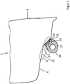
- the Figure 1 shows a schematic representation of a cross section through a lower region of a body component 2 in the form of a door of a vehicle, the reference number 4 denoting the door outer skin and the reference number 6 denoting the door bottom.
- the sheet metal of the door bottom 6 has a normal course with several bends or arches.
- a region is marked with the reference number 8 in which a surface 10 of the body component 2 to be applied with a sealing profile 20 undercuts with an adjacent surface 12 angled to it.
- the sealing profile 20 is preferably a hollow profile seal with a hose part 22, a sealing base 24 and a sealing slot 26 between the hose part 22 and the sealing base 24.
- the sealing slot 26 opens in the direction of the surface 12, so that between the sealing slot 26 and the surface 12 has an undercut.
- the sealing profile is held on the surface 10 via an adhesive strip 28. In the closed state, the body component 2 can be sealed against a side sill area of the vehicle via the sealing profile 20.
- the Figure 2 shows a situation in which the sealing profile 20 is held by a pressure strip 30 according to the invention before the sealing profile 20 is applied to the body component 2.
- the sealing profile 20 or the adhesive strip 28 is held at a distance from the surface 10 of the body component 2.
- the pressure bar 30 is in the Figure 2 shown in a first embodiment which is shaped L-shaped in cross section.
- the pressure strip 30 comprises a retaining tab 32 and a pressure web 34 arranged essentially at right angles thereto.
- the retaining tab 32 and the pressure web 34 are formed in one piece, both being made from one workpiece or being detachably assembled from at least two components.
- the retaining tab 32 is designed to engage in the sealing slot 26 in order to hold the sealing profile 20, in particular to hold it in the position shown, in order to apply the sealing profile 20 on the surface 10 of the body component 2 via the adhesive strip 28.
- the pressing web 34 is connected to a setting actuator 36 which can be operated hydraulically or pneumatically.
- the setting actuator 36 in turn, can be attached to a base element of the application system, not shown overall.
- a plurality of adjusting actuators 36 and respective pressure strips 30 are arranged in the longitudinal direction of the sealing profile 20, so that the sealing profile 20 has the full circumference of the in Figure 2
- the position shown with respect to the body component 2 may have.
- the sealing profile is brought into this relative position via the base element, for example via manipulation by an industrial robot.
- the sealing profile 20 can be fed in sections via the respective setting actuator 36 onto the body component 2 for application.
- a pressing force can now be applied directly to the sealing base 24 via the pressure strip 30 according to the invention the outside of which the adhesive strip 28 is already attached.
- the pressure strip 30 according to the invention is particularly advantageous when the sealing profile is to be applied in the area of an undercut of the body component 2.
- the width of the sealing profile 20, while it is pushed onto the retaining tab 32 increases only by the amount of the thickness of the pressure web 34, that is, insignificantly.
- a retaining groove 38 can be provided on the retaining tab 32, into which the material of the sealing profile 20 can engage in a form-fitting manner.
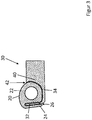
- the Figure 3 shows a further embodiment of a pressure strip 30 according to the invention, in which the pressure web 34 is designed such that it comprises a contour section 40 which at least partially wraps around the hose part 22 of the sealing profile 20 when the sealing profile 20 is placed on the pressure strip 30.
- the contour section 40 together with the holding tab 32, encloses the predominant part of the hose part 22, so that the contour section 40 and the holding tab 32 form a receiving channel 42.
- the sealing profile 20 is thus held twice by the pressure strip 30, namely once via the retaining tab 32 inserted into the sealing slot 26 and also via the hose part 22 seated between the retaining tab 32 and the contour section 40.
Landscapes
- Engineering & Computer Science (AREA)
- Mechanical Engineering (AREA)
- Gasket Seals (AREA)
- Seal Device For Vehicle (AREA)
Description
- Die Erfindung betrifft eine Andruckleiste zum Halten und Andrücken eines Dichtungsprofils, insbesondere einer Hohlprofildichtung, über eine Applikationsanlage für Karosseriebauteile.
- Im Stand der Technik ist ein Verfahren zum Anbringen eines Dichtungsprofils auf einem Karosseriebauteil bekannt, bei dem bereits vorkonfektionierte beziehungsweise abgelängte Dichtungsprofile in einem Magazin bevorratet werden und auf das Karosseriebauteil, bei dem es sich beispielsweise um einen Türzusammenbau handeln kann, appliziert werden. Hierbei kommt eine sogenannte Applikationsanlage zum Einsatz, die komplementär zu einer Fläche des Karosseriebauteils, auf der das Dichtungsprofil appliziert werden soll, ausgebildet ist. Die Applikationsanlage umfasst eine Vielzahl von umfänglich angeordneten und benachbarten Andruckelementen, die nach einer Vorpositionierung der mit dem Dichtungsprofil bestückten Applikationsanlage unmittelbar vor dem Karosseriebauteil über eine geeignete Stellaktorik an das Karosseriebauteil zugestellt werden können, um das Dichtungsprofil auf der Fläche des Karosseriebauteil zu applizieren. Hierbei kommt eine sogenannte Klebetechnik zum Einsatz, bei der auf dem Dichtungsprofil bereits ein Klebestoff beziehungsweise Klebemittel in Längsrichtung aufgebracht ist. Dieses Klebemittel ist mit einem Schutz in Form eines Liners abgedeckt, so dass dieser Liner während des Applikationsprozesses des Dichtungsprofils auf das Karosseriebauteil durch die Applikationsanlage abgezogen werden muss. Bei der Stellaktorik kann es sich beispielsweise um hydraulisch oder pneumatische betätigte Kolben-Zylinder-Anordnungen handeln. In der
EP 0 849 106 B1 ist eine Andruckelement einer Applikationsanlage beschrieben, bei dem das Dichtungselement zunächst über eine Halteleiste gehalten wird und anschließend, nachdem das Dichtungsprofil über die Applikationseinheit an das Karosseriebauteil vorpositioniert wurde, über eine Andrückeinrichtung an das Karosseriebauteil angedrückt wird, so dass sich der Klebestreifen an die Fläche des Karosseriebauteils anlegt und verklebt. Der insgesamt sehr bauraumbeanspruchenden Ausgestaltung der Aufnahme des Dichtungsprofils über die gerade ausgebildeten Halteleisten sind dann Grenzen gesetzt, wenn sich der Blechbereich des Karosseriebauteils in dem Bereich der Applikationsfläche einwölbt, so dass sich die Einschubrichtung der Haltleisten in einen Dichtungsschlitz des Dichtungsprofils und die benachbarte Kontur des Blechteils hinterschneiden, also ein Hinterschnitt vorliegt. Weiterhin erfordert die Andrückeinrichtung derEP 0 849 106 B1 einen verhältnismäßig großen Zustellweg, da zunächst das Schlauchteil des Dichtungsprofils komprimiert werden muss, bevor eine Andrückkraft auf den Dichtungsfuß aufgebracht wird, auf dessen Außenseite der Klebestreifen aufgebracht ist. DokumentDE 10 2010 050 410 zeigt eine gattungsgemäße Andrückleiste. Die DokumenteDE 196 52 459 undEP 2 913 211 zeigen weitere Stand der Technik Andrückleisten. - Ausgehend hiervon besteht die Aufgabe der vorliegenden Erfindung darin, eine Andrückleiste für eine Applikationsanlage bereitzustellen, die sowohl die Funktion des Haltens des Dichtungsprofils in der vorpositionierten Stellung vor dem Karosseriebauteil als auch die Funktion des Andrückens des Dichtungsprofils an das Karosseriebauteil vereint.
- Die Aufgabe wird gelöst durch eine Andrückleiste zum Halten und Andrücken eines Dichtungsprofils, insbesondere einer Hohlprofildichtung, über eine Applikationsanlage für Karosseriebauteile, umfassend eine Haltelasche zum Halten des Dichtungsprofils und einen Andrücksteg, wobei die Haltelasche und der Andrücksteg einstückig ausgebildet sind und die Haltelasche über den Andrücksteg gegen eine mit dem Dichtungsprofil zu applizierende Fläche des Karosseriebauteils mit einer Andrückkraft beaufschlagbar ist. Die erfindungsgemäße Andrückleiste ermöglicht die Verwendung eines Stellaktuators mit einem kürzeren Stellweg, da nun nicht mehr ein Leerweg infolge des Zusammendrückens des Schlauchteils überwunden werden muss. Bei Verwendung eines Andrückzylinders, pneumatisch oder hydraulisch betätigt, kann dieser mit einem kürzeren Hub ausgeführt werden. Da die Andrückkraft nunmehr unmittelbar über die Haltelasche auf den Dichtungsfuß wirkt, muss keine Energie mehr für das Zusammendrücken des Schlauchteils aufwendet werden. Die Energieeinsparung kann beispielsweise in einem deutlich niedrigeren Druckluftverbrauch bestehen. Insgesamt werden eine größere Positioniergenauigkeit und eine bessere Andruckverteilung des Dichtungsprofils auf dem Karosseriebauteil erzielt, da der Anpressdruck unmittelbarer auf den Dichtungsfuß übertragen wird.
- Eine vorteilhafte Ausgestaltung der Erfindung sieht vor, dass die Haltelasche und der Andrucksteg im Wesentlichen rechtwinklig zueinander angeordnet sind. Hierdurch ergibt sich eine besonders kompakte Gestalt der Andrückleiste, da die Breite der Andrückleiste annähernd der Breite des Dichtungsprofils entspricht. Hierdurch ist es möglich das Dichtungsprofil in Bereich eines Hinterschnitts der Haltelasche mit dem benachbarten Blechbereich des Karosseriebauteils zu applizieren.
- Eine vorteilhafte Ausgestaltung der Erfindung sieht vor, dass auf einer der zu applizierenden Fläche des Karosseriebauteils abgewandten Stirnfläche der Haltelasche eine quer zu einer Wirkrichtung der Andrücckraft verlaufende Haltenut angeordnet ist, zum formschlüssigen Eingriff eines Umfangsbereich des Schlauchteils des Dichtungsprofils in die Haltenut. Hierdurch sind ein sicheres Aufstecken und ein sicherer Halt des Dichtungsprofils auf der Halteleiste gewährleistet.
- Eine vorteilhafte Ausgestaltung der Erfindung sieht vor, dass die Haltelasche und der Andrucksteg einen quer zu einer Wirkrichtung der Andruckkraft verlaufenden Aufnahmekanal ausbilden, zur Aufnahme zumindest eines Teils des Schlauchteils der Hohlprofildichtung. Hierdurch kann eine weitere Verbesserung des Halts des Dichtungsprofils auf der Haltleiste erreicht werden, beispielsweise wenn das Dichtungsprofil unter einem Radius gehalten und appliziert werden muss, um zu vermeiden, dass sich das Dichtungsprofil infolge der Eigenspannung von der Halteleiste löst.
- Die Erfindung wird nachfolgend mit weiteren Merkmalen, Einzelheiten und Vorteilen anhand der beigefügten Figuren erläutert. Die Figuren illustrieren dabei lediglich beispielhafte Ausführungsformen der Erfindung. Hierin zeigen
- Figur 1
- eine schematische Darstellung eines unteren Bereichs eines Karosseriebauteil mit einem Dichtungsprofil;
- Figur 2
- eine schematische Darstellung eines unteren Bereichs eines Karosseriebauteil mit einem Dichtungsprofil und einer erfindungsgemäßen Andrückleiste in einer ersten Ausführungsform und
- Figur 3
- eine erfindungsgemäße Andrückleiste in einer weiteren erfindungsgemäßen Ausführungsform mit einem Dichtungsprofil.
- Die
Figur 1 zeigt in schematischer Darstellung einen Querschnitt durch einen unteren Bereich eines Karosseriebauteils 2 in Form einer Tür eines Fahrzeugs, wobei mit dem Bezugszeichen 4 die Türaußenhaut und mit dem Bezugszeichen 6 der Türboden bezeichnet ist. Das Blech des Türbodens 6 hat einen üblichen Verlauf mit mehreren Biegungen beziehungsweise Wölbungen. Mit dem Bezugszeichen 8 ist ein Bereich markiert, in dem sich eine mit einem Dichtungsprofil 20 zu applizierende Fläche 10 des Karosseriebauteils 2 mit einer benachbarten, hierzu abgewinkelten Fläche 12 hinterschneidet. Bei dem Dichtungsprofil 20 handelt es sich bevorzugt um eine Hohlprofildichtung mit einem Schlauchteil 22, einem Dichtungsfuß 24 und einem Dichtungsschlitz 26 zwischen dem Schlauchteil 22 und dem Dichtungsfuß 24. Der Dichtungsschlitz 26 öffnet sich in Richtung der Fläche 12, so dass auch zwischen dem Dichtungsschlitz 26 und der Fläche 12 ein Hinterschnitt vorliegt. Das Dichtungsprofil ist über einen Klebestreifen 28 an der Fläche 10 gehalten. Über das Dichtungsprofil 20 kann die Karosseriebauteil 2 im geschlossenen Zustand beispielsweise gegen einen Seitenschwellerbereich des Fahrzeugs gedichtet sein. - Die
Figur 2 zeigt eine Situation, in der das Dichtungsprofil 20 von einer erfindungsgemäßen Andrückleiste 30 gehalten ist, bevor das Dichtungsprofil 20 an dem Karosseriebauteil 2 appliziert wird. Hierbei ist das Dichtungsprofil 20 beziehungsweise der Klebestreifen 28 beabstandet zu der Fläche 10 des Karosseriebauteils 2 gehalten. Die Andrückleiste 30 ist in derFigur 2 in einer ersten Ausführungsform gezeigt, die im Querschnitt L-förmig geformt ist. Die Andrückleiste 30 umfasst eine Haltelasche 32 und einen hierzu im Wesentlichen rechtwinklig angeordneten Andrücksteg 34. Die Haltelasche 32 und der Andrücksteg 34 sind einstückig ausgebildet, wobei beide entweder aus einem Werkstück gefertigt sind oder aus zumindest zwei Bauteilen lösbar zusammengesetzt sind. Die Haltelasche 32 ist dazu ausgebildet, in den Dichtungsschlitz 26 einzugreifen, um hierüber das Dichtungsprofil 20 zu halten, insbesondere in der dargestellten Position zu halten, um ausgehend hiervon das Dichtungsprofil 20 auf der Fläche 10 des Karosseriebauteils 2 über den Klebestreifen 28 zu applizieren. Der Andrücksteg 34 ist vorliegend mit einem Stellaktuator 36 verbunden, der hydraulisch oder pneumatisch betätigt sein kann. Der Stellaktuator 36 wiederum kann an einem Grundelement der insgesamt nicht gezeigten Applikationsanlage befestigt sein. In Längsrichtung des Dichtungsprofils 20 sind eine Mehrzahl an Stellaktuatoren 36 und jeweilige Andrückleisten 30 angeordnet, so dass das Dichtungsprofil 20 vollumfänglich die inFigur 2 gezeigte Lage bezüglich des Karosseriebauteils 2 haben kann. In diese relative Lage wiederum wird das Dichtungsprofil über das Grundelement, beispielsweise über die Handhabung durch einen Industrieroboter, gebracht. Ausgehend von dieser relativen Lage kann das Dichtungsprofil 20 abschnittsweise über den jeweiligen Stellaktuator 36 auf das Karosseriebauteil 2 zur Applikation zugestellt werden. Über die erfindungsgemäße Andrückleiste 30 kann nun unmittelbar eine Andrückkraft auf den Dichtungsfuß 24 aufgebracht werden, an dessen Außenseite der Klebestreifen 28 bereits angebracht ist. Die erfindungsgemäße Andrückleiste 30 ist aber insbesondere dann von Vorteil, wenn das Dichtungsprofil in dem Bereich eines Hinterschnitts des Karosseriebauteils 2 appliziert werden soll. Durch die bevorzugt L-förmige Gestaltung der Andrückleiste 30 erhöht sich die Breite des Dichtungsprofils 20, während es auf die Haltelasche 32 aufgesteckt ist, lediglich um das Maß der Dicke des Andrückstegs 34, also unwesentlich. Um einen festen Sitz des Dichtungsprofils 20 auf der Haltelasche 32 zu gewährleisten, kann an der Haltelasche 32 eine Haltenut 38 vorgesehen sein, in die Material des Dichtungsprofils 20 formschlüssig eingreifen kann. - Die
Figur 3 zeigt eine weitere Ausführungsform einer erfindungsgemäßen Andrückleiste 30, bei der der Andrücksteg 34 derart ausgestaltet ist, dass er einen Konturabschnitt 40 umfasst, der sich um das Schlauchteil 22 des Dichtungsprofil 20 zumindest teilweise herumlegt, wenn das Dichtungsprofil 20 auf die Andrückleiste 30 gesteckt ist. Der Konturabschnitt 40 umschließt zusammen mit der Haltelasche 32 den überwiegenden Teil des Schlauchteils 22, so dass Konturabschnitt 40 und Haltelasche 32 einen Aufnahmekanal 42 bilden. Bei dieser Ausführungsform ist das Dichtungsprofil 20 somit zweifach von der Andrückleiste 30 gehalten, nämlich einmal über die in den Dichtungsschlitz 26 gesteckte Haltelasche 32 und außerdem über den zwischen Haltelasche 32 und Konturabschnitt 40 einsitzenden Schlauchteil 22. -
- 2
- Karosseriebauteil
- 4
- Türaußenhaut
- 6
- Türboden
- 8
- Hinterschnitt
- 10
- Fläche
- 12
- Fläche
- 20
- Dichtungsprofil
- 22
- Schlauchteil
- 24
- Dichtungsfuß
- 26
- Dichtungsschlitz
- 28
- Klebestreifen
- 30
- Andrückleiste
- 32
- Haltelasche
- 34
- Andrücksteg
- 36
- Stellaktuator
- 38
- Haltenut
- 40
- Konturabschnitt
- 42
- Aufnahmekanal
Claims (3)
- Andrückleiste (30) zum Halten und Andrücken eines Dichtungsprofils (20), insbesondere einer Hohlprofildichtung, über eine Applikationsanlage für Karosseriebauteile (2), umfassend eine Haltelasche (32) zum Halten des Dichtungsprofils (20) und einen Andrücksteg (34), gekennzeichnet dadurch dass die Haltelasche (32) und der Andrücksteg (34) einstückig ausgebildet und im Wesentlichen rechtwinklig zueinander angeordnet sind und die Haltelasche (32) über den Andrücksteg (34) gegen eine mit dem Dichtungsprofil (20) zu applizierende Fläche(10) des Karosseriebauteils (2) mit einer Andrückkraft beaufschlagbar ist.
- Andrückleiste (30) nach Anspruch 1 , dadurch gekennzeichnet, dass auf einer der zu applizierenden Fläche des Karosseriebauteils (2) abgewandten Stirnfläche der Haltelasche (32) eine quer zu einer Wirkrichtung der Andrückkraft verlaufende Haltenut (38) angeordnet ist, zum formschlüssigen Eingriff eines Umfangsbereich des Schlauchteils (22) des Dichtungsprofils (2) in die Haltenut (38).
- Andrückleiste (30) nach einem der Ansprüche 1 oder 2, dadurch gekennzeichnet, dass die Haltelasche (32) und der Andrücksteg (34) einen quer zu einer Wirkrichtung der Andrückkraft verlaufenden Aufnahmekanal (42) ausbilden, zur Aufnahme zumindest eines Teils des Schlauchteils (22) der Hohlprofildichtung (20)
Priority Applications (1)
| Application Number | Priority Date | Filing Date | Title |
|---|---|---|---|
| PL18195796T PL3459771T3 (pl) | 2017-09-25 | 2018-09-20 | Listwa dociskowa do przytrzymywania i dociskania profilu uszczelniającego |
Applications Claiming Priority (1)
| Application Number | Priority Date | Filing Date | Title |
|---|---|---|---|
| DE202017105787.9U DE202017105787U1 (de) | 2017-09-25 | 2017-09-25 | Andruckleiste zum Halten und Andrücken eines Dichtungsprofils |
Publications (2)
| Publication Number | Publication Date |
|---|---|
| EP3459771A1 EP3459771A1 (de) | 2019-03-27 |
| EP3459771B1 true EP3459771B1 (de) | 2020-11-04 |
Family
ID=63678421
Family Applications (1)
| Application Number | Title | Priority Date | Filing Date |
|---|---|---|---|
| EP18195796.0A Active EP3459771B1 (de) | 2017-09-25 | 2018-09-20 | Andruckleiste zum halten und andrücken eines dichtungsprofils |
Country Status (5)
| Country | Link |
|---|---|
| EP (1) | EP3459771B1 (de) |
| DE (1) | DE202017105787U1 (de) |
| ES (1) | ES2840548T3 (de) |
| HU (1) | HUE053126T2 (de) |
| PL (1) | PL3459771T3 (de) |
Family Cites Families (5)
| Publication number | Priority date | Publication date | Assignee | Title |
|---|---|---|---|---|
| DE19652459A1 (de) * | 1996-12-17 | 1998-06-18 | Thyssen Industrie | Halteleiste für eine Dichtung, insbesondere in einer Applikationsanlage für Kfz-Türen |
| DE10142288B4 (de) * | 2001-03-27 | 2006-04-20 | Saargummi Gmbh | Trägerprofil und Verbindungsbereich für Dichtungsprofile an Automobilkarosserien |
| DE102010018298B4 (de) * | 2010-04-23 | 2013-05-29 | Grohmann Engineering Gmbh | Halteleiste |
| DE102010050410A1 (de) * | 2010-11-04 | 2011-06-22 | Daimler AG, 70327 | Applikationswerkzeug für Kraftfahrzeug-Dichtprofile |
| JP5936638B2 (ja) * | 2014-02-28 | 2016-06-22 | 西川ゴム工業株式会社 | 車両のルーフシール構造 |
-
2017
- 2017-09-25 DE DE202017105787.9U patent/DE202017105787U1/de active Active
-
2018
- 2018-09-20 HU HUE18195796A patent/HUE053126T2/hu unknown
- 2018-09-20 ES ES18195796T patent/ES2840548T3/es active Active
- 2018-09-20 PL PL18195796T patent/PL3459771T3/pl unknown
- 2018-09-20 EP EP18195796.0A patent/EP3459771B1/de active Active
Non-Patent Citations (1)
| Title |
|---|
| None * |
Also Published As
| Publication number | Publication date |
|---|---|
| ES2840548T3 (es) | 2021-07-06 |
| EP3459771A1 (de) | 2019-03-27 |
| DE202017105787U1 (de) | 2019-01-09 |
| HUE053126T2 (hu) | 2021-06-28 |
| PL3459771T3 (pl) | 2021-05-17 |
Similar Documents
| Publication | Publication Date | Title |
|---|---|---|
| DE69317303T3 (de) | Selbststanzende nieten | |
| EP0759134B1 (de) | Verschlussvorrichtung und verfahren zum verschliessen von druckmittel führenden kanälen in einem gehäuse | |
| WO2000025080A1 (de) | Rohrverbindung zwischen einem sammler eines kraftfahrzeugwärmetauschers und einer äusseren rohrleitung | |
| EP1373000A1 (de) | Verfahren und vorrichtung zum aufbringen von trägerprofilen fur gummidichtungen an automobilkarosserieteilen und trägerprofil | |
| EP1250547A1 (de) | Anschlussvorrichtung für eine fluidleitung | |
| EP0857626B1 (de) | Baugruppe aus einem Gasgenerator und einem Abströmrohr für ein Fahrzeuginsassen-Rückhaltesystem | |
| EP2841217A1 (de) | Verfahren zum biegen eines verbundblechs und solches gebogenes verbundblech | |
| DE102011120147A1 (de) | Dichtungsanordnung für Öffnung einerKraftfahrzeugkarosserie | |
| EP1175323B1 (de) | Pneumatischer bremskraftverstärker | |
| DE60019645T2 (de) | Schlauchklemme mit stufenloser klemmfläche und verfahren zu ihrer herstellung | |
| DE102010009026A1 (de) | Verfahren und Vorrichtung zum Herstellen einer Stanznietverbindung sowie Stanznietverbindung, insbesondere für den Automobilbau | |
| EP2346727A1 (de) | Verfahren zur herstellung einer formschlüssigen verbindung zwischen zwei bauteilen eines in einem fahrzeug befindlichen aggregats, -werkzeug und -aggregat | |
| DE102005001548A1 (de) | Vorrichtung zum Betätigen eines Verriegelungsmechanismus | |
| DE10257818A1 (de) | Stutzen für eine Behälterwand | |
| EP3459771A1 (de) | Andruckleiste zum halten und andrücken eines dichtungsprofils | |
| EP2446980A2 (de) | Rohr und Verfahren zur Bearbeitung von Rohrenden | |
| DE102019217985A1 (de) | Anordnung eines Aktors an einem Stellelement sowie Verfahren zur Herstellung einer Anordnung eines Aktors an einem Stellelement | |
| EP0895819A1 (de) | Verfahren und Vorrichtung zur Herstellung einer Montageanbindung an einem Hohlprofil | |
| DE102011116196B3 (de) | Fügeverbindung und Verfahren zur Herstellung | |
| DE202017106935U1 (de) | Andrückvorrichtung für ein Dichtungsprofil | |
| DE3634596A1 (de) | Verfahren und vorrichtung zur herstellung von karosserieteilen in verbundtechnik | |
| EP2095890B1 (de) | Verfahren zur Umformung eines Hohlprofilbauteils mittels Innenhochdruck | |
| DE10323740B4 (de) | Baugruppe, mit einem Stanzniet und mindestens zwei zu verbindenden Bauteilen | |
| EP1378700B1 (de) | Verbindung zwischen einem Rohr und einem Fitting, Fitting für eine solche Verbindung sowie Verfahren für die Montage | |
| DE102013205468B4 (de) | Verfahren zur Herstellung eines Anlageabschnittes zur Befestigung eines weiteren Bauteils an einem Zylinderrohr für einen Schwingungsdämpfer |
Legal Events
| Date | Code | Title | Description |
|---|---|---|---|
| PUAI | Public reference made under article 153(3) epc to a published international application that has entered the european phase |
Free format text: ORIGINAL CODE: 0009012 |
|
| STAA | Information on the status of an ep patent application or granted ep patent |
Free format text: STATUS: THE APPLICATION HAS BEEN PUBLISHED |
|
| AK | Designated contracting states |
Kind code of ref document: A1 Designated state(s): AL AT BE BG CH CY CZ DE DK EE ES FI FR GB GR HR HU IE IS IT LI LT LU LV MC MK MT NL NO PL PT RO RS SE SI SK SM TR |
|
| AX | Request for extension of the european patent |
Extension state: BA ME |
|
| STAA | Information on the status of an ep patent application or granted ep patent |
Free format text: STATUS: REQUEST FOR EXAMINATION WAS MADE |
|
| 17P | Request for examination filed |
Effective date: 20190927 |
|
| RBV | Designated contracting states (corrected) |
Designated state(s): AL AT BE BG CH CY CZ DE DK EE ES FI FR GB GR HR HU IE IS IT LI LT LU LV MC MK MT NL NO PL PT RO RS SE SI SK SM TR |
|
| GRAP | Despatch of communication of intention to grant a patent |
Free format text: ORIGINAL CODE: EPIDOSNIGR1 |
|
| STAA | Information on the status of an ep patent application or granted ep patent |
Free format text: STATUS: GRANT OF PATENT IS INTENDED |
|
| INTG | Intention to grant announced |
Effective date: 20200617 |
|
| RIN1 | Information on inventor provided before grant (corrected) |
Inventor name: HAUPENTHAL, HORST-GUENTER Inventor name: WEBER, THOMAS |
|
| GRAS | Grant fee paid |
Free format text: ORIGINAL CODE: EPIDOSNIGR3 |
|
| RIN1 | Information on inventor provided before grant (corrected) |
Inventor name: HAUPENTHAL, HORST-GUENTER Inventor name: WEBER, THOMAS |
|
| GRAA | (expected) grant |
Free format text: ORIGINAL CODE: 0009210 |
|
| STAA | Information on the status of an ep patent application or granted ep patent |
Free format text: STATUS: THE PATENT HAS BEEN GRANTED |
|
| AK | Designated contracting states |
Kind code of ref document: B1 Designated state(s): AL AT BE BG CH CY CZ DE DK EE ES FI FR GB GR HR HU IE IS IT LI LT LU LV MC MK MT NL NO PL PT RO RS SE SI SK SM TR |
|
| REG | Reference to a national code |
Ref country code: GB Ref legal event code: FG4D Free format text: NOT ENGLISH |
|
| REG | Reference to a national code |
Ref country code: CH Ref legal event code: EP |
|
| REG | Reference to a national code |
Ref country code: AT Ref legal event code: REF Ref document number: 1330375 Country of ref document: AT Kind code of ref document: T Effective date: 20201115 |
|
| REG | Reference to a national code |
Ref country code: DE Ref legal event code: R096 Ref document number: 502018002909 Country of ref document: DE |
|
| REG | Reference to a national code |
Ref country code: IE Ref legal event code: FG4D Free format text: LANGUAGE OF EP DOCUMENT: GERMAN |
|
| REG | Reference to a national code |
Ref country code: SE Ref legal event code: TRGR |
|
| REG | Reference to a national code |
Ref country code: NL Ref legal event code: MP Effective date: 20201104 |
|
| PG25 | Lapsed in a contracting state [announced via postgrant information from national office to epo] |
Ref country code: FI Free format text: LAPSE BECAUSE OF FAILURE TO SUBMIT A TRANSLATION OF THE DESCRIPTION OR TO PAY THE FEE WITHIN THE PRESCRIBED TIME-LIMIT Effective date: 20201104 Ref country code: PT Free format text: LAPSE BECAUSE OF FAILURE TO SUBMIT A TRANSLATION OF THE DESCRIPTION OR TO PAY THE FEE WITHIN THE PRESCRIBED TIME-LIMIT Effective date: 20210304 Ref country code: RS Free format text: LAPSE BECAUSE OF FAILURE TO SUBMIT A TRANSLATION OF THE DESCRIPTION OR TO PAY THE FEE WITHIN THE PRESCRIBED TIME-LIMIT Effective date: 20201104 Ref country code: NO Free format text: LAPSE BECAUSE OF FAILURE TO SUBMIT A TRANSLATION OF THE DESCRIPTION OR TO PAY THE FEE WITHIN THE PRESCRIBED TIME-LIMIT Effective date: 20210204 Ref country code: GR Free format text: LAPSE BECAUSE OF FAILURE TO SUBMIT A TRANSLATION OF THE DESCRIPTION OR TO PAY THE FEE WITHIN THE PRESCRIBED TIME-LIMIT Effective date: 20210205 |
|
| PG25 | Lapsed in a contracting state [announced via postgrant information from national office to epo] |
Ref country code: BG Free format text: LAPSE BECAUSE OF FAILURE TO SUBMIT A TRANSLATION OF THE DESCRIPTION OR TO PAY THE FEE WITHIN THE PRESCRIBED TIME-LIMIT Effective date: 20210204 Ref country code: IS Free format text: LAPSE BECAUSE OF FAILURE TO SUBMIT A TRANSLATION OF THE DESCRIPTION OR TO PAY THE FEE WITHIN THE PRESCRIBED TIME-LIMIT Effective date: 20210304 Ref country code: LV Free format text: LAPSE BECAUSE OF FAILURE TO SUBMIT A TRANSLATION OF THE DESCRIPTION OR TO PAY THE FEE WITHIN THE PRESCRIBED TIME-LIMIT Effective date: 20201104 |
|
| REG | Reference to a national code |
Ref country code: LT Ref legal event code: MG9D |
|
| REG | Reference to a national code |
Ref country code: HU Ref legal event code: AG4A Ref document number: E053126 Country of ref document: HU |
|
| PG25 | Lapsed in a contracting state [announced via postgrant information from national office to epo] |
Ref country code: HR Free format text: LAPSE BECAUSE OF FAILURE TO SUBMIT A TRANSLATION OF THE DESCRIPTION OR TO PAY THE FEE WITHIN THE PRESCRIBED TIME-LIMIT Effective date: 20201104 |
|
| REG | Reference to a national code |
Ref country code: ES Ref legal event code: FG2A Ref document number: 2840548 Country of ref document: ES Kind code of ref document: T3 Effective date: 20210706 |
|
| PG25 | Lapsed in a contracting state [announced via postgrant information from national office to epo] |
Ref country code: LT Free format text: LAPSE BECAUSE OF FAILURE TO SUBMIT A TRANSLATION OF THE DESCRIPTION OR TO PAY THE FEE WITHIN THE PRESCRIBED TIME-LIMIT Effective date: 20201104 Ref country code: RO Free format text: LAPSE BECAUSE OF FAILURE TO SUBMIT A TRANSLATION OF THE DESCRIPTION OR TO PAY THE FEE WITHIN THE PRESCRIBED TIME-LIMIT Effective date: 20201104 Ref country code: SK Free format text: LAPSE BECAUSE OF FAILURE TO SUBMIT A TRANSLATION OF THE DESCRIPTION OR TO PAY THE FEE WITHIN THE PRESCRIBED TIME-LIMIT Effective date: 20201104 Ref country code: SM Free format text: LAPSE BECAUSE OF FAILURE TO SUBMIT A TRANSLATION OF THE DESCRIPTION OR TO PAY THE FEE WITHIN THE PRESCRIBED TIME-LIMIT Effective date: 20201104 Ref country code: EE Free format text: LAPSE BECAUSE OF FAILURE TO SUBMIT A TRANSLATION OF THE DESCRIPTION OR TO PAY THE FEE WITHIN THE PRESCRIBED TIME-LIMIT Effective date: 20201104 |
|
| REG | Reference to a national code |
Ref country code: DE Ref legal event code: R097 Ref document number: 502018002909 Country of ref document: DE |
|
| PG25 | Lapsed in a contracting state [announced via postgrant information from national office to epo] |
Ref country code: DK Free format text: LAPSE BECAUSE OF FAILURE TO SUBMIT A TRANSLATION OF THE DESCRIPTION OR TO PAY THE FEE WITHIN THE PRESCRIBED TIME-LIMIT Effective date: 20201104 |
|
| PLBE | No opposition filed within time limit |
Free format text: ORIGINAL CODE: 0009261 |
|
| STAA | Information on the status of an ep patent application or granted ep patent |
Free format text: STATUS: NO OPPOSITION FILED WITHIN TIME LIMIT |
|
| 26N | No opposition filed |
Effective date: 20210805 |
|
| PG25 | Lapsed in a contracting state [announced via postgrant information from national office to epo] |
Ref country code: IT Free format text: LAPSE BECAUSE OF FAILURE TO SUBMIT A TRANSLATION OF THE DESCRIPTION OR TO PAY THE FEE WITHIN THE PRESCRIBED TIME-LIMIT Effective date: 20201104 Ref country code: NL Free format text: LAPSE BECAUSE OF FAILURE TO SUBMIT A TRANSLATION OF THE DESCRIPTION OR TO PAY THE FEE WITHIN THE PRESCRIBED TIME-LIMIT Effective date: 20201104 Ref country code: AL Free format text: LAPSE BECAUSE OF FAILURE TO SUBMIT A TRANSLATION OF THE DESCRIPTION OR TO PAY THE FEE WITHIN THE PRESCRIBED TIME-LIMIT Effective date: 20201104 |
|
| PG25 | Lapsed in a contracting state [announced via postgrant information from national office to epo] |
Ref country code: SI Free format text: LAPSE BECAUSE OF FAILURE TO SUBMIT A TRANSLATION OF THE DESCRIPTION OR TO PAY THE FEE WITHIN THE PRESCRIBED TIME-LIMIT Effective date: 20201104 |
|
| REG | Reference to a national code |
Ref country code: CH Ref legal event code: PL |
|
| REG | Reference to a national code |
Ref country code: BE Ref legal event code: MM Effective date: 20210930 |
|
| PG25 | Lapsed in a contracting state [announced via postgrant information from national office to epo] |
Ref country code: IS Free format text: LAPSE BECAUSE OF FAILURE TO SUBMIT A TRANSLATION OF THE DESCRIPTION OR TO PAY THE FEE WITHIN THE PRESCRIBED TIME-LIMIT Effective date: 20210304 Ref country code: MC Free format text: LAPSE BECAUSE OF FAILURE TO SUBMIT A TRANSLATION OF THE DESCRIPTION OR TO PAY THE FEE WITHIN THE PRESCRIBED TIME-LIMIT Effective date: 20201104 |
|
| PG25 | Lapsed in a contracting state [announced via postgrant information from national office to epo] |
Ref country code: LU Free format text: LAPSE BECAUSE OF NON-PAYMENT OF DUE FEES Effective date: 20210920 Ref country code: IE Free format text: LAPSE BECAUSE OF NON-PAYMENT OF DUE FEES Effective date: 20210920 Ref country code: FR Free format text: LAPSE BECAUSE OF NON-PAYMENT OF DUE FEES Effective date: 20210930 Ref country code: BE Free format text: LAPSE BECAUSE OF NON-PAYMENT OF DUE FEES Effective date: 20210930 |
|
| PG25 | Lapsed in a contracting state [announced via postgrant information from national office to epo] |
Ref country code: LI Free format text: LAPSE BECAUSE OF NON-PAYMENT OF DUE FEES Effective date: 20210930 Ref country code: CH Free format text: LAPSE BECAUSE OF NON-PAYMENT OF DUE FEES Effective date: 20210930 |
|
| PG25 | Lapsed in a contracting state [announced via postgrant information from national office to epo] |
Ref country code: CY Free format text: LAPSE BECAUSE OF FAILURE TO SUBMIT A TRANSLATION OF THE DESCRIPTION OR TO PAY THE FEE WITHIN THE PRESCRIBED TIME-LIMIT Effective date: 20201104 |
|
| PG25 | Lapsed in a contracting state [announced via postgrant information from national office to epo] |
Ref country code: MK Free format text: LAPSE BECAUSE OF FAILURE TO SUBMIT A TRANSLATION OF THE DESCRIPTION OR TO PAY THE FEE WITHIN THE PRESCRIBED TIME-LIMIT Effective date: 20201104 |
|
| REG | Reference to a national code |
Ref country code: DE Ref legal event code: R081 Ref document number: 502018002909 Country of ref document: DE Owner name: THYSSENKRUPP AUTOMOTIVE BODY SOLUTIONS GMBH, DE Free format text: FORMER OWNERS: THYSSENKRUPP AG, 45143 ESSEN, DE; THYSSENKRUPP SYSTEM ENGINEERING GMBH, 74076 HEILBRONN, DE Ref country code: DE Ref legal event code: R081 Ref document number: 502018002909 Country of ref document: DE Owner name: THYSSENKRUPP AG, DE Free format text: FORMER OWNERS: THYSSENKRUPP AG, 45143 ESSEN, DE; THYSSENKRUPP SYSTEM ENGINEERING GMBH, 74076 HEILBRONN, DE |
|
| PG25 | Lapsed in a contracting state [announced via postgrant information from national office to epo] |
Ref country code: TR Free format text: LAPSE BECAUSE OF FAILURE TO SUBMIT A TRANSLATION OF THE DESCRIPTION OR TO PAY THE FEE WITHIN THE PRESCRIBED TIME-LIMIT Effective date: 20201104 |
|
| PG25 | Lapsed in a contracting state [announced via postgrant information from national office to epo] |
Ref country code: MT Free format text: LAPSE BECAUSE OF FAILURE TO SUBMIT A TRANSLATION OF THE DESCRIPTION OR TO PAY THE FEE WITHIN THE PRESCRIBED TIME-LIMIT Effective date: 20201104 |
|
| REG | Reference to a national code |
Ref country code: AT Ref legal event code: MM01 Ref document number: 1330375 Country of ref document: AT Kind code of ref document: T Effective date: 20230920 |
|
| PG25 | Lapsed in a contracting state [announced via postgrant information from national office to epo] |
Ref country code: AT Free format text: LAPSE BECAUSE OF NON-PAYMENT OF DUE FEES Effective date: 20230920 |
|
| PG25 | Lapsed in a contracting state [announced via postgrant information from national office to epo] |
Ref country code: AT Free format text: LAPSE BECAUSE OF NON-PAYMENT OF DUE FEES Effective date: 20230920 |
|
| PGFP | Annual fee paid to national office [announced via postgrant information from national office to epo] |
Ref country code: DE Payment date: 20250919 Year of fee payment: 8 |
|
| PGFP | Annual fee paid to national office [announced via postgrant information from national office to epo] |
Ref country code: PL Payment date: 20250915 Year of fee payment: 8 |
|
| PGFP | Annual fee paid to national office [announced via postgrant information from national office to epo] |
Ref country code: HU Payment date: 20250922 Year of fee payment: 8 Ref country code: GB Payment date: 20250919 Year of fee payment: 8 |
|
| PGFP | Annual fee paid to national office [announced via postgrant information from national office to epo] |
Ref country code: SE Payment date: 20250918 Year of fee payment: 8 |
|
| PGFP | Annual fee paid to national office [announced via postgrant information from national office to epo] |
Ref country code: CZ Payment date: 20250916 Year of fee payment: 8 |
|
| PGFP | Annual fee paid to national office [announced via postgrant information from national office to epo] |
Ref country code: ES Payment date: 20251030 Year of fee payment: 8 |
|
| PGFP | Annual fee paid to national office [announced via postgrant information from national office to epo] |
Ref country code: AT Payment date: 20260410 Year of fee payment: 5 |