EP2913211A1 - Seal structure for vehicle roof - Google Patents
Seal structure for vehicle roof Download PDFInfo
- Publication number
- EP2913211A1 EP2913211A1 EP15154507.6A EP15154507A EP2913211A1 EP 2913211 A1 EP2913211 A1 EP 2913211A1 EP 15154507 A EP15154507 A EP 15154507A EP 2913211 A1 EP2913211 A1 EP 2913211A1
- Authority
- EP
- European Patent Office
- Prior art keywords
- roof
- opening
- edge portion
- weather strip
- corner
- Prior art date
- Legal status (The legal status is an assumption and is not a legal conclusion. Google has not performed a legal analysis and makes no representation as to the accuracy of the status listed.)
- Granted
Links
Images
Classifications
-
- B—PERFORMING OPERATIONS; TRANSPORTING
- B60—VEHICLES IN GENERAL
- B60J—WINDOWS, WINDSCREENS, NON-FIXED ROOFS, DOORS, OR SIMILAR DEVICES FOR VEHICLES; REMOVABLE EXTERNAL PROTECTIVE COVERINGS SPECIALLY ADAPTED FOR VEHICLES
- B60J10/00—Sealing arrangements
- B60J10/45—Assembling sealing arrangements with vehicle parts
-
- B—PERFORMING OPERATIONS; TRANSPORTING
- B60—VEHICLES IN GENERAL
- B60J—WINDOWS, WINDSCREENS, NON-FIXED ROOFS, DOORS, OR SIMILAR DEVICES FOR VEHICLES; REMOVABLE EXTERNAL PROTECTIVE COVERINGS SPECIALLY ADAPTED FOR VEHICLES
- B60J10/00—Sealing arrangements
- B60J10/30—Sealing arrangements characterised by the fastening means
- B60J10/34—Sealing arrangements characterised by the fastening means using adhesives
- B60J10/35—Sealing arrangements characterised by the fastening means using adhesives using adhesive tapes, e.g. double-sided tapes
-
- B—PERFORMING OPERATIONS; TRANSPORTING
- B60—VEHICLES IN GENERAL
- B60J—WINDOWS, WINDSCREENS, NON-FIXED ROOFS, DOORS, OR SIMILAR DEVICES FOR VEHICLES; REMOVABLE EXTERNAL PROTECTIVE COVERINGS SPECIALLY ADAPTED FOR VEHICLES
- B60J10/00—Sealing arrangements
- B60J10/80—Sealing arrangements specially adapted for opening panels, e.g. doors
- B60J10/82—Sealing arrangements specially adapted for opening panels, e.g. doors for movable panels in roofs
Definitions
- the present disclosure relates to a seal structure for a roof of a vehicle having a retractable or removable roof, such as convertibles, vehicles having a T-bar roof, vehicles having a targa-top roof, etc.
- upper and lower directions designate upper and lower directions of a vehicle.
- Japanese Unexamined Patent Publication No. H09-164850 describes a seal structure for a convertible having a roof panel removably attached to a roof.
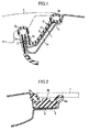
- the seal structure includes a header weather strip 3 sealing between an edge portion 1 of an opening in a body panel of the convertible and an edge portion of a roof panel 4.
- the edge portion 1 of the opening of the body panel includes an inclined part 1a extending obliquely downward toward the inside of the vehicle, and a flange 1b protruding obliquely upward toward the outside of the vehicle from a lower end of the inclined part 1a.
- a shoulder part 1c is formed at an upper end the inclined part 1a.
- the header weather strip 3 includes a grip part 3a in which a core metal 2 is embedded. The grip part 3a is fitted on the flange 1b.
- a hollow main sealing part 3b protrudes upward from an upper end of the grip part 3a.
- the header weather strip 3 further includes an extension part 3c extending obliquely upward from a sidewall of the grip part 3a along the inclined part 1a.
- a hollow sub sealing part 3d is provided at an upper end of the extension part 3c to seat on the shoulder part 1c.
- the hollow main sealing part 3b of the grip part 3a elastically contacts the roof panel 4
- the hollow sub sealing part 3d on the shoulder part 1c elastically contacts the edge portion of the roof panel 4.
- An EPTSEALER (registered trademark) 5 is provided between the inclined part 1a and the extension part 3c.
- Japanese Unexamined Patent Publication No. H07-101251 describes a seal structure between a roof center and a hatch roof 7 of a vehicle with a T-bar roof
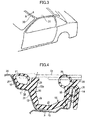
- a weather strip 9 is provided in a gutter part 8 of the roof center to which the hatch roof 7 is attached.
- the weather strip 9 includes a hollow sealing part 9a which elastically contacts the hatch roof 7 to seal an outer edge portion of the hatch roof 7, and a stopper 9 which receives and supports the outer edge portion of the hatch roof 7.
- the header weather strip 3 of the seal structure disclosed by Japanese Unexamined Patent Publication No. H09-164850 is supported by fitting the grip part 3a on the flange 1b.
- the sealing part 3d and the extension part 3c are attached to the shoulder part 1c and the inclined part 1a, respectively, using a fixture or the like means to prevent visual defects or water leakage due to separation of the sealing part 3d and the extension part 3c from the edge portion of the opening of the body panel.
- a double-sided tape can be used to attach the weather strip.
- the weather strip cannot easily be adhered to the edge portion of the opening with the double-sided tape while supporting the sealing part 3d without misalignment of the sealing part 3d.
- the present disclosure provides a seal structure for a roof which makes it possible to surely and easily fix and adhere a sealing part or an extension part of a weather strip to an edge portion of an opening of the roof with a double-sided tape.
- a seal structure for a roof of a vehicle having an opening closed by a retractable or removable roof panel includes: a weather strip which is attached to an edge portion of the opening of the roof, and elastically contacts an outer edge portion of the roof panel closing the opening to seal between the roof panel and the opening.
- the edge portion of the opening of the roof includes a lower inclined part extending obliquely downward toward an inside of the vehicle, a shoulder part extending from an upper end of the lower inclined part with a corner formed between the shoulder part and the lower inclined part, and an upper inclined part extending obliquely upward from the shoulder part.
- the weather strip includes a first sealing part which is attached to the shoulder part, and elastically contacts the outer edge portion of the roof panel closing the opening of the roof, an inclined extension part extending obliquely downward from the first sealing part along the lower inclined part, and a first stopper (23) protruding upward from the first sealing part in a direction opposite to the inclined extension part to receive the outer edge portion of the roof panel closing the opening of the roof.
- misalignment of the weather strip is controlled by the corner, a locating face on a bottom of the first sealing part is pressed onto the shoulder part on one side of the corner, and a locating face of the inclined extension part is pressed onto the lower inclined part on the other side of the corner, and the first sealing part is adhered to at least one of the shoulder part or the upper inclined part with a double-sided tape.
- the seal structure can prevent the possibility of visual defects or water leakage due to separation of the first sealing part or the inclined extension part from the edge portion of the opening of the roof.
- the stopper protruding upward from the first sealing part in the direction opposite to the inclined extension part can be pinched with fingers, or an exclusive jig can engage with the stopper.
- the stopper in attaching the weather strip to the edge portion of the opening of the roof, the stopper can easily be pressed onto the corner formed by the shoulder part and the lower inclined part of the roof by pinching the stopper with the fingers or engaging the exclusive jig with the stopper.
- misalignment of the weather strip can be controlled by the corner, and a pressing force is applied to a bottom surface of the first sealing part and the inclined extension part to press the locating face on the bottom of the first sealing part onto the shoulder part on one side of the corner, and to press the locating face of the inclined extension part onto the lower inclined part on the other side of the corner.
- a pressing force is applied to a bottom surface of the first sealing part and the inclined extension part to press the locating face on the bottom of the first sealing part onto the shoulder part on one side of the corner, and to press the locating face of the inclined extension part onto the lower inclined part on the other side of the corner.
- a side surface of the stopper facing the opening of the roof and a side surface of the inclined extension part form a surface extending smoothly and continuously to a vicinity of a lower end of the inclined extension part.
- the edge portion of the opening of the roof further includes a flange which is located closer to the opening of the roof than the lower inclined part and protrudes upward
- the weather strip further includes a grip part fitted on the flange, and a second sealing part protruding upward from an upper end of the grip part to elastically contact the roof panel closing the opening of the roof.
- the first sealing part and the second sealing part of the weather strip elastically contact the roof panel to provide a double seal structure, thereby improving sealing between the weather strip and the roof panel. Since the one side of the weather strip is adhered to the edge portion of the opening of the roof by the double-sided tape, and the grip part on the other side of the weather strip is fitted on the flange at the edge portion of the opening of the roof, the weather strip can more surely be held at the edge portion of the opening of the roof.
- the weather strip further includes a second stopper protruding upward from the upper end of the grip part to receive the roof panel closing the opening of the roof.
- the roof panel can stably be supported by the two stoppers provided on an inner circumferential side and an outer circumferential side of the weather strip, i.e., the first and second stoppers.
- the edge portion of the opening of the roof further includes an extension part extending transversely from a lower end of the lower inclined part toward the opening of the roof, and a gap is formed between the lower end of the inclined extension part of the weather strip and the extension part.
- a lower end of the extension part is not caught by the extension part of the roof.
- the adhering can easily be performed, and the first sealing part does not separate from the shoulder part.
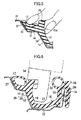
- a convertible shown in FIG. 3 includes a roof 30 of a vehicle body, and a roof panel 31 attached to an edge portion of an opening of the roof 30.
- the edge portion of the opening of the roof 30 includes a lower inclined part 12 extending obliquely downward toward the inside of the vehicle, a shoulder part 11 extending from an upper end of the lower inclined part 12, an upper inclined part 10 extending obliquely upward from the shoulder part 11, an extension part 13 extending substantially horizontally from a lower end of the lower inclined part 12 toward the opening of the roof 30, and a flange 14 protruding upward from the extension part 13 at an end of the roof 30 closer to the opening.
- the shoulder part 11 and the lower inclined part 12 have flat surfaces, and are connected through a corner 15.
- a weather strip 16 is detachably attached to the edge portion of the opening of the roof 30.
- the weather strip 16 is made of a rubber-like elastic body, such as EPDM rubber, thermoplastic elastomers, etc., and is formed by extrusion.
- the weather strip 16 includes a hollow sealing part 17 as a first sealing part attached to the shoulder part 11, an inclined extension part 18 extending obliquely downward along the lower inclined part 12 from the first sealing part 17, a grip part 20 embedded with a core metal 19 and fitted on the flange 14, and a coupling part 21 extending substantially horizontally to couple a lower end of the inclined extension part 18 and the grip part 20.
- the weather strip 16 further includes a first stopper 23 which is located adjacent to the first sealing part 17 to be closer to the opening of the roof 30 than the first sealing part 17, and protrudes upward in a direction opposite to the inclined extension part 18, a hollow sealing part 25 as a second sealing part protruding upward from an upper end of the grip part 20, and a second stopper 26 which is located adjacent to the second sealing part 25 to be closer to the opening of the roof 30 than the second sealing part 25, and protrudes upward from an upper end of the grip part 20.
- a double-sided tape 27 having a release paper on one side (registered trademark; 3M) is adhered to a side surface of the first sealing part 17, and the release paper is removed from the double-sided tape 27. Then, a corner formed by a locating face 28 on the bottom of the first sealing part 17 and a locating face 29 of the inclined extension part 18 is fixed to a corner 15 of the edge portion of the opening of the roof 30, the locating face 28 of the first sealing part 17 is fixed to the shoulder part 11, and the locating face 29 of the inclined extension part 18 is fixed to the lower inclined part 12.
- misalignment of the weather strip 16 is controlled by the corner 15.
- the first stopper 23 is pinched with fingers, and pressed in a direction of an arrow shown in FIG.
- the first sealing part 17 is squashed and pressed onto the upper inclined part 10 as shown in FIG. 5 .
- the side surface of the first sealing part 17 is adhered to the upper inclined part 10 extending upward from the shoulder part 11 with the double-sided tape 27.
- one side of the weather strip 16 is adhered to the edge portion of the opening of the roof 30.
- a side surface 23a of the first stopper 23 facing the opening of the roof 30 is curved in the shape of a recess to be continuous with a side surface of the inclined extension part 18 extending along the lower inclined part 12 of the edge portion of the opening of the roof 30 so that the pressing force generated when the first stopper 23 is pressed in the direction of the arrow shown in FIG. 4 , i.e., toward the corner 15, is easily divided to the first sealing part 17 and the inclined extension part 18.
- the side surface 23a of the first stopper 23 and the side surface of the inclined extension part 18 form a smoothly and continuously curved surface extending to a vicinity of a lower end of the inclined extension part 18.
- the stopper 23 can easily be pinched with the fingers, and the locating face 29 of the inclined extension part 18 can easily be pressed onto the lower inclined part 12.
- a top surface of the first stopper 23 is substantially parallel with the shoulder part 11. Accordingly, the pressing force applied to both of the shoulder part 11 and the inclined part 12 is naturally generated when the first stopper 23 is pinched with a finger placed on the side surface 23a facing the inside of the vehicle and a finger placed on the top surface of the first stopper 23 as shown in FIG. 5 .
- the first stopper 23 is pinched with the fingers and pressed toward the corner 15 to press the locating face 28 onto the shoulder part 11 on the one side of the corner 15, and to press the locating face 29 onto the inclined part 12 on the other side of the corner 15.
- an exclusive jig may be used.
- FIG. 6 shows an example of use of an exclusive jig 33.
- the exclusive jig 33 has a substantially J-shaped cross section, and includes a top pressing part 34 which contacts the top surface of the first stopper 23, and a side pressing part 35 which contacts the side surface 23a of the first stopper 23.
- the exclusive jig 23 is attached to an automatic device which is not shown, and is configured to attach the weather strip 16 in the same manner as in the above-described embodiment by pressing the first stopper 23 from above with the top pressing part 34, and laterally pressing the side surface 23a of the first stopper 23 with the side pressing part 35 as shown in FIG. 6 .
- a recessed groove may be formed at a boundary between the locating face 28 of the first sealing part 17 and the locating face 29 of the inclined extension part 18 to form a gap between the boundary and the corner 15 so that the boundary between the locating face 28 and the locating face 29 do not interfere with the corner 15.
- FIG. 4 shows the weather strip 16 attached to the edge portion of the opening of the roof 30.
- a lower end of the inclined extension part 18 and the coupling part 21 of the weather strip 16 are located above the extension part 13 of the edge portion of the opening of the roof 30 to form a gap s therebetween. With the presence of the gap, the lower end of the inclined extension part 18 is not caught by the extension part 13 when the first sealing part 17 is adhered to the shoulder part 11, and the first sealing part 17 does not separate from the shoulder part 11.
- the whole coupling part 21 is located above the extension part 13 with a gap formed therebetween.
- part or most part of the coupling part 21 may contact the extension part 13 as long as the lower end of the inclined extension part 18 is separated from the extension part 13 so that the lower end of the inclined extension part 18 is not caught by the extension part 13 in adhering the first sealing part 17 to the shoulder part 11.
- the weather strip 16 is pressed onto the edge portion of the opening of the roof 30 by the force applied in the direction of the arrow shown in FIG. 4 with the misalignment of the weather strip 16 being controlled by the corner 15. Therefore, the weather strip 16 is not misaligned by the attaching of the roof panel 31.
- One or both of the locating faces 28 and 29 can be adhered with the double-sided tape or a butyl sealant.
- the load of the roof panel 31 presses the locating faces 28 and 29 to enhance the adhesion of the locating faces 28 and 29 to the roof 30 with the double-sided tape, etc. This can surely prevent the weather strip 16 from separating and detaching from the roof.
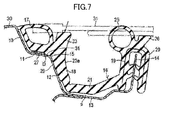
- FIG. 7 shows a seal structure for a roof of a second embodiment.
- the first sealing part 17 is fixed and adhered not at the side surface, but at the bottom surface.
- Other features of the second embodiment are the same as those of the first embodiment.
- the first sealing part 17 on the one side of the weather strip 16 is adhered to the shoulder part 11 of the edge portion of the opening of the roof 30.
- a step D is provided in the bottom surface of the first sealing part 17, and the double-sided tape 27 is provided in a recess formed by the step D.
- part of the bottom surface of the first sealing part 17 closer to the opening of the roof 30 than the step D serves as a locating face 31.
- the locating face 29 of the inclined extension part 18 is brought into contact with the lower inclined part 12, and then the first stopper 23 is pressed in a direction of an arrow shown in FIG. 7 toward the corner 15 in the same manner as in the first embodiment.
- the pressing force is applied from the first sealing part 17 to the shoulder part 11, thereby fixing and adhering the first sealing part 17 to the shoulder part 11.
- the roof panel 31 is sealed at two positions, i.e., at the outer edge by the first sealing part 17, and at the part inside of the outer edge by the second sealing part 25, and is supported by the first stopper 23 and the second stopper 26.
- the disclosed weather strip 16 does not essentially include the grip part 20 including the second sealing part 25 and the second stopper 26, and the coupling part 21, and these parts may be omitted. When these parts are omitted, the weather strip 16 is constituted of the first sealing part 17, the inclined extension part 18, and the first stopper 23.
- the roof panel 31 of the above-described embodiments is removable.
- the roof panel 31 may be retractable without removing from the roof.
- the seal structure for the roof is applied to a header on a front side of a convertible.
- the seal structure can also be applied to a rear side of the convertible, and can also be applied to the edge portion of the opening of the roof of other vehicles than the convertibles, such as vehicles with a T-bar roof, vehicles with a targa-top roof, etc.
Landscapes
- Engineering & Computer Science (AREA)
- Mechanical Engineering (AREA)
- Seal Device For Vehicle (AREA)
Abstract
Description
- The present disclosure relates to a seal structure for a roof of a vehicle having a retractable or removable roof, such as convertibles, vehicles having a T-bar roof, vehicles having a targa-top roof, etc. In the present specification, upper and lower directions designate upper and lower directions of a vehicle.
- As shown in
FIG. 1 , Japanese Unexamined Patent Publication No.H09-164850 header weather strip 3 sealing between an edge portion 1 of an opening in a body panel of the convertible and an edge portion of a roof panel 4. - The edge portion 1 of the opening of the body panel includes an
inclined part 1a extending obliquely downward toward the inside of the vehicle, and aflange 1b protruding obliquely upward toward the outside of the vehicle from a lower end of theinclined part 1a. Ashoulder part 1c is formed at an upper end theinclined part 1a. Theheader weather strip 3 includes agrip part 3a in which acore metal 2 is embedded. Thegrip part 3a is fitted on theflange 1b. A hollow main sealingpart 3b protrudes upward from an upper end of thegrip part 3a. Theheader weather strip 3 further includes an extension part 3c extending obliquely upward from a sidewall of thegrip part 3a along theinclined part 1a. A hollowsub sealing part 3d is provided at an upper end of the extension part 3c to seat on theshoulder part 1c. - When the roof panel 4 is attached to the roof, the hollow main sealing
part 3b of thegrip part 3a elastically contacts the roof panel 4, and the hollowsub sealing part 3d on theshoulder part 1c elastically contacts the edge portion of the roof panel 4. An EPTSEALER (registered trademark) 5 is provided between theinclined part 1a and the extension part 3c. - As shown in
FIG. 2 , Japanese Unexamined Patent Publication No.H07-101251 FIG. 2 , aweather strip 9 is provided in agutter part 8 of the roof center to which the hatch roof 7 is attached. Theweather strip 9 includes ahollow sealing part 9a which elastically contacts the hatch roof 7 to seal an outer edge portion of the hatch roof 7, and astopper 9 which receives and supports the outer edge portion of the hatch roof 7. - The
header weather strip 3 of the seal structure disclosed by Japanese Unexamined Patent Publication No.H09-164850 grip part 3a on theflange 1b. However, more desirably, the sealingpart 3d and the extension part 3c are attached to theshoulder part 1c and theinclined part 1a, respectively, using a fixture or the like means to prevent visual defects or water leakage due to separation of the sealingpart 3d and the extension part 3c from the edge portion of the opening of the body panel. - To solve this problem, a double-sided tape can be used to attach the weather strip. However, there is no place where fingers of a worker or an exclusive jig can be supported around the sealing
part 3d, and the weather strip cannot easily be adhered to the edge portion of the opening with the double-sided tape while supporting the sealingpart 3d without misalignment of the sealingpart 3d. - The present disclosure provides a seal structure for a roof which makes it possible to surely and easily fix and adhere a sealing part or an extension part of a weather strip to an edge portion of an opening of the roof with a double-sided tape.
- Disclosed is a seal structure for a roof of a vehicle having an opening closed by a retractable or removable roof panel, the seal structure includes: a weather strip which is attached to an edge portion of the opening of the roof, and elastically contacts an outer edge portion of the roof panel closing the opening to seal between the roof panel and the opening.
- The edge portion of the opening of the roof includes a lower inclined part extending obliquely downward toward an inside of the vehicle, a shoulder part extending from an upper end of the lower inclined part with a corner formed between the shoulder part and the lower inclined part, and an upper inclined part extending obliquely upward from the shoulder part.
- The weather strip includes a first sealing part which is attached to the shoulder part, and elastically contacts the outer edge portion of the roof panel closing the opening of the roof, an inclined extension part extending obliquely downward from the first sealing part along the lower inclined part, and a first stopper (23) protruding upward from the first sealing part in a direction opposite to the inclined extension part to receive the outer edge portion of the roof panel closing the opening of the roof.
- Misalignment of the weather strip is controlled by the corner, a locating face on a bottom of the first sealing part is pressed onto the shoulder part on one side of the corner, and a locating face of the inclined extension part is pressed onto the lower inclined part on the other side of the corner, and the first sealing part is adhered to at least one of the shoulder part or the upper inclined part with a double-sided tape.
- The seal structure can prevent the possibility of visual defects or water leakage due to separation of the first sealing part or the inclined extension part from the edge portion of the opening of the roof. The stopper protruding upward from the first sealing part in the direction opposite to the inclined extension part can be pinched with fingers, or an exclusive jig can engage with the stopper. Thus, in attaching the weather strip to the edge portion of the opening of the roof, the stopper can easily be pressed onto the corner formed by the shoulder part and the lower inclined part of the roof by pinching the stopper with the fingers or engaging the exclusive jig with the stopper. With the stopper being pressed in this way, misalignment of the weather strip can be controlled by the corner, and a pressing force is applied to a bottom surface of the first sealing part and the inclined extension part to press the locating face on the bottom of the first sealing part onto the shoulder part on one side of the corner, and to press the locating face of the inclined extension part onto the lower inclined part on the other side of the corner. This can surely prevent the misalignment of the weather strip. As a result, the first sealing part can easily be adhered to at least one of the shoulder part or the upper inclined part. When the opening of the roof is closed by the roof panel, a pressure applied to the stopper by the roof panel is transmitted to the bottom surface of the first sealing part and the inclined extension part as in the case of the attaching of the weather strip, thereby pressing the bottom surface of the first sealing part and the inclined extension part onto the shoulder part and the lower inclined part, respectively. Thus, the misalignment of the weather strip can be prevented.
- In a preferred embodiment, a side surface of the stopper facing the opening of the roof and a side surface of the inclined extension part form a surface extending smoothly and continuously to a vicinity of a lower end of the inclined extension part. Thus, when the stopper is pressed onto the corner, the pressing force can efficiently be transmitted to the bottom surface of the first sealing part and the inclined extension part.
- In a preferred embodiment, the edge portion of the opening of the roof further includes a flange which is located closer to the opening of the roof than the lower inclined part and protrudes upward, and the weather strip further includes a grip part fitted on the flange, and a second sealing part protruding upward from an upper end of the grip part to elastically contact the roof panel closing the opening of the roof.
- According to the preferred embodiment, the first sealing part and the second sealing part of the weather strip elastically contact the roof panel to provide a double seal structure, thereby improving sealing between the weather strip and the roof panel. Since the one side of the weather strip is adhered to the edge portion of the opening of the roof by the double-sided tape, and the grip part on the other side of the weather strip is fitted on the flange at the edge portion of the opening of the roof, the weather strip can more surely be held at the edge portion of the opening of the roof.
- In a preferred embodiment, the weather strip further includes a second stopper protruding upward from the upper end of the grip part to receive the roof panel closing the opening of the roof.
- According to the preferred embodiment, the roof panel can stably be supported by the two stoppers provided on an inner circumferential side and an outer circumferential side of the weather strip, i.e., the first and second stoppers.
- In a preferred embodiment, the edge portion of the opening of the roof further includes an extension part extending transversely from a lower end of the lower inclined part toward the opening of the roof, and a gap is formed between the lower end of the inclined extension part of the weather strip and the extension part.
- According to the preferred embodiment, in adhering the first sealing part of the weather strip to the shoulder part of the roof with the double-sided tape, a lower end of the extension part is not caught by the extension part of the roof. Thus, the adhering can easily be performed, and the first sealing part does not separate from the shoulder part.
-
-
FIG. 1 is a cross-sectional view showing an example of a conventional seal structure for a roof. -
FIG. 2 is a cross-sectional view showing another example of the conventional seal structure for the roof. -
FIG. 3 is a perspective view showing part of an appearance of a convertible. -
FIG. 4 is a cross-sectional view showing a seal structure for a roof of the present disclosure taken along the line A-A inFIG. 3 . -
FIG. 5 is a cross-sectional view showing a first stopper pinched with fingers and pressed toward a corner of an edge portion of an opening of a roof -
FIG. 6 is a cross-sectional view showing the first stopper pressed toward the corner of the edge portion of the opening of the roof using an exclusive jig. -
FIG. 7 is a cross-sectional view showing another embodiment of the seal structure for the roof of the present disclosure. - Embodiments of the present disclosure will be described below with reference to the drawings. The following preferred embodiments are provided merely for the illustration purpose, and do not limit the present disclosure, application, and use thereof.
- A convertible shown in
FIG. 3 includes aroof 30 of a vehicle body, and aroof panel 31 attached to an edge portion of an opening of theroof 30. - As shown in
FIG. 4 , the edge portion of the opening of theroof 30 includes a lowerinclined part 12 extending obliquely downward toward the inside of the vehicle, ashoulder part 11 extending from an upper end of the lowerinclined part 12, an upperinclined part 10 extending obliquely upward from theshoulder part 11, anextension part 13 extending substantially horizontally from a lower end of the lowerinclined part 12 toward the opening of theroof 30, and aflange 14 protruding upward from theextension part 13 at an end of theroof 30 closer to the opening. Theshoulder part 11 and the lowerinclined part 12 have flat surfaces, and are connected through acorner 15. - A
weather strip 16 is detachably attached to the edge portion of the opening of theroof 30. Theweather strip 16 is made of a rubber-like elastic body, such as EPDM rubber, thermoplastic elastomers, etc., and is formed by extrusion. Theweather strip 16 includes ahollow sealing part 17 as a first sealing part attached to theshoulder part 11, aninclined extension part 18 extending obliquely downward along the lowerinclined part 12 from thefirst sealing part 17, agrip part 20 embedded with acore metal 19 and fitted on theflange 14, and acoupling part 21 extending substantially horizontally to couple a lower end of theinclined extension part 18 and thegrip part 20. - The
weather strip 16 further includes afirst stopper 23 which is located adjacent to the first sealingpart 17 to be closer to the opening of theroof 30 than the first sealingpart 17, and protrudes upward in a direction opposite to theinclined extension part 18, a hollow sealingpart 25 as a second sealing part protruding upward from an upper end of thegrip part 20, and asecond stopper 26 which is located adjacent to the second sealingpart 25 to be closer to the opening of theroof 30 than the second sealingpart 25, and protrudes upward from an upper end of thegrip part 20. - A method of assembling the
weather strip 16 to the edge portion of the opening of theroof 30 will be described below. - A double-
sided tape 27 having a release paper on one side (registered trademark; 3M) is adhered to a side surface of the first sealingpart 17, and the release paper is removed from the double-sided tape 27. Then, a corner formed by a locatingface 28 on the bottom of the first sealingpart 17 and a locatingface 29 of theinclined extension part 18 is fixed to acorner 15 of the edge portion of the opening of theroof 30, the locatingface 28 of the first sealingpart 17 is fixed to theshoulder part 11, and the locatingface 29 of theinclined extension part 18 is fixed to the lowerinclined part 12. Thus, misalignment of theweather strip 16 is controlled by thecorner 15. In this state, thefirst stopper 23 is pinched with fingers, and pressed in a direction of an arrow shown inFIG. 4 , i.e., toward thecorner 15. Then, a pressing force is applied to the first sealingpart 17 and theinclined extension part 18, and the locatingface 28 on the bottom of the first sealingpart 17 is pressed onto theshoulder part 11 on one side of thecorner 15, while the locatingface 29 on a side surface of theinclined extension part 18 is pressed onto the lowerinclined part 12 on the other side of thecorner 15. - Subsequent to the pressing of the
first stopper 23, the first sealingpart 17 is squashed and pressed onto the upperinclined part 10 as shown inFIG. 5 . By squashing the first sealingpart 17, the side surface of the first sealingpart 17 is adhered to the upperinclined part 10 extending upward from theshoulder part 11 with the double-sided tape 27. Thus, one side of theweather strip 16 is adhered to the edge portion of the opening of theroof 30. - As shown in
FIGS. 4 and5 , aside surface 23a of thefirst stopper 23 facing the opening of theroof 30 is curved in the shape of a recess to be continuous with a side surface of theinclined extension part 18 extending along the lowerinclined part 12 of the edge portion of the opening of theroof 30 so that the pressing force generated when thefirst stopper 23 is pressed in the direction of the arrow shown inFIG. 4 , i.e., toward thecorner 15, is easily divided to the first sealingpart 17 and theinclined extension part 18. Specifically, theside surface 23a of thefirst stopper 23 and the side surface of theinclined extension part 18 form a smoothly and continuously curved surface extending to a vicinity of a lower end of theinclined extension part 18. Thus, thestopper 23 can easily be pinched with the fingers, and the locatingface 29 of theinclined extension part 18 can easily be pressed onto the lowerinclined part 12. A top surface of thefirst stopper 23 is substantially parallel with theshoulder part 11. Accordingly, the pressing force applied to both of theshoulder part 11 and theinclined part 12 is naturally generated when thefirst stopper 23 is pinched with a finger placed on theside surface 23a facing the inside of the vehicle and a finger placed on the top surface of thefirst stopper 23 as shown inFIG. 5 . - In the above-described embodiment, the
first stopper 23 is pinched with the fingers and pressed toward thecorner 15 to press the locatingface 28 onto theshoulder part 11 on the one side of thecorner 15, and to press the locatingface 29 onto theinclined part 12 on the other side of thecorner 15. In place of the fingers, an exclusive jig may be used. -
FIG. 6 shows an example of use of anexclusive jig 33. Theexclusive jig 33 has a substantially J-shaped cross section, and includes a toppressing part 34 which contacts the top surface of thefirst stopper 23, and aside pressing part 35 which contacts theside surface 23a of thefirst stopper 23. Theexclusive jig 23 is attached to an automatic device which is not shown, and is configured to attach theweather strip 16 in the same manner as in the above-described embodiment by pressing thefirst stopper 23 from above with thetop pressing part 34, and laterally pressing theside surface 23a of thefirst stopper 23 with theside pressing part 35 as shown inFIG. 6 . - In attaching the
weather strip 16 to the edge portion of the opening, a recessed groove may be formed at a boundary between the locatingface 28 of the first sealingpart 17 and the locatingface 29 of theinclined extension part 18 to form a gap between the boundary and thecorner 15 so that the boundary between the locatingface 28 and the locatingface 29 do not interfere with thecorner 15. - The one side of the
weather strip 16 is attached to the edge portion of the opening of theroof 30 as described above (adhered to the edge portion of the opening of theroof 30 with the double-sided tape 27). Before or after the attaching, thegrip part 20 on the other side of theweather strip 16 is fitted on theflange 14.FIG. 4 shows theweather strip 16 attached to the edge portion of the opening of theroof 30. A lower end of theinclined extension part 18 and thecoupling part 21 of theweather strip 16 are located above theextension part 13 of the edge portion of the opening of theroof 30 to form a gap s therebetween. With the presence of the gap, the lower end of theinclined extension part 18 is not caught by theextension part 13 when the first sealingpart 17 is adhered to theshoulder part 11, and the first sealingpart 17 does not separate from theshoulder part 11. - In the illustrated first embodiment, the
whole coupling part 21 is located above theextension part 13 with a gap formed therebetween. However, part or most part of thecoupling part 21 may contact theextension part 13 as long as the lower end of theinclined extension part 18 is separated from theextension part 13 so that the lower end of theinclined extension part 18 is not caught by theextension part 13 in adhering the first sealingpart 17 to theshoulder part 11. - When the
removable roof panel 31 is attached to the roof as indicated by a dot-and-dash line inFIG. 4 , an outer edge portion of theroof panel 31 elastically contacts the first sealingpart 17 and squashes the first sealingpart 17. Thus, the roof of the vehicle is sealed, and theroof panel 31 is received and supported by thefirst stopper 23. With theroof panel 31 being attached, a load pressing thestopper 23 in the direction of the arrow shown inFIG. 4 , i.e., toward thecorner 15, is applied by theroof panel 31 due to the presence of thecurved side surface 23a of thestopper 23, and the locating faces 28 and 29 are pressed onto theshoulder part 11 and theinclined part 12 in the same manner as the locating faces 28 and 29 are pressed in attaching theweather strip 16. Thus, just like the case of attaching theweather strip 16, theweather strip 16 is pressed onto the edge portion of the opening of theroof 30 by the force applied in the direction of the arrow shown inFIG. 4 with the misalignment of theweather strip 16 being controlled by thecorner 15. Therefore, theweather strip 16 is not misaligned by the attaching of theroof panel 31. - One or both of the locating faces 28 and 29 can be adhered with the double-sided tape or a butyl sealant. When the
roof panel 31 is attached to theroof 30, the load of theroof panel 31 presses the locating faces 28 and 29 to enhance the adhesion of the locating faces 28 and 29 to theroof 30 with the double-sided tape, etc. This can surely prevent theweather strip 16 from separating and detaching from the roof. -
FIG. 7 shows a seal structure for a roof of a second embodiment. In the second embodiment, the first sealingpart 17 is fixed and adhered not at the side surface, but at the bottom surface. Other features of the second embodiment are the same as those of the first embodiment. - As described above, in the second embodiment, the first sealing
part 17 on the one side of theweather strip 16 is adhered to theshoulder part 11 of the edge portion of the opening of theroof 30. A step D is provided in the bottom surface of the first sealingpart 17, and the double-sided tape 27 is provided in a recess formed by the step D. In this structure, part of the bottom surface of the first sealingpart 17 closer to the opening of theroof 30 than the step D serves as a locatingface 31. In attaching theweather strip 16, the locatingface 29 of theinclined extension part 18 is brought into contact with the lowerinclined part 12, and then thefirst stopper 23 is pressed in a direction of an arrow shown inFIG. 7 toward thecorner 15 in the same manner as in the first embodiment. Thus, the pressing force is applied from the first sealingpart 17 to theshoulder part 11, thereby fixing and adhering the first sealingpart 17 to theshoulder part 11. - Part of the
roof panel 31 inside of an outer edge thereof elastically contacts the second sealingpart 25, and is received and supported by thesecond stopper 26. Thus, theroof panel 31 is sealed at two positions, i.e., at the outer edge by the first sealingpart 17, and at the part inside of the outer edge by the second sealingpart 25, and is supported by thefirst stopper 23 and thesecond stopper 26. - The disclosed
weather strip 16 does not essentially include thegrip part 20 including the second sealingpart 25 and thesecond stopper 26, and thecoupling part 21, and these parts may be omitted. When these parts are omitted, theweather strip 16 is constituted of the first sealingpart 17, theinclined extension part 18, and thefirst stopper 23. - The
roof panel 31 of the above-described embodiments is removable. However, theroof panel 31 may be retractable without removing from the roof. - In the above-described embodiments, the seal structure for the roof is applied to a header on a front side of a convertible. However, the seal structure can also be applied to a rear side of the convertible, and can also be applied to the edge portion of the opening of the roof of other vehicles than the convertibles, such as vehicles with a T-bar roof, vehicles with a targa-top roof, etc.
Claims (5)
- A seal structure for a roof (30) of a vehicle having an opening closed by a retractable or removable roof panel (31), the seal structure comprising:a weather strip (16) which is attached to an edge portion of the opening of the roof (30), and elastically contacts an outer edge portion of the roof panel (31) closing the opening to seal between the roof panel (31) and the edge portion, whereinthe edge portion of the opening of the roof (30) includes a lower inclined part (12) extending obliquely downward toward an inside of the vehicle, a shoulder part (11) extending from an upper end of the lower inclined part (12) with a corner (15) formed between the shoulder part (11) and the lower inclined part (12), and an upper inclined part (10) extending obliquely upward from the shoulder part (11),the weather strip (16) includes a first sealing part (17) which is attached to the shoulder part (11), and elastically contacts the outer edge portion of the roof panel (31) closing the opening of the roof (30), an inclined extension part (18) extending obliquely downward from the first sealing part (17) along the lower inclined part (12), and a first stopper (23) protruding upward from the first sealing part (17) in a direction opposite to the inclined extension part (18) to receive the outer edge portion of the roof panel (31) closing the opening of the roof (30),misalignment of the weather strip (16) is controlled by the corner (15),a locating face (28) on a bottom of the first sealing part (17) is pressed onto the shoulder part (11) on one side of the corner (15), and a locating face (29) of the inclined extension part (18) is pressed onto the lower inclined part (12) on the other side of the corner (15), andthe first sealing part (17) is adhered to at least one of the shoulder part (11) or the upper inclined part (10) with a double-sided tape.
- The seal structure for the roof (30) of the vehicle of claim 1, wherein
a side surface (23a) of the first stopper (23) facing the opening of the roof (30) and a side surface of the inclined extension part (18) form a surface extending smoothly and continuously to a vicinity of a lower end of the inclined extension part (18). - The seal structure for the roof (30) of the vehicle of claim 1 or 2, wherein the edge portion of the opening of the roof (30) further includes a flange (14) which is located closer to the opening of the roof (30) than the lower inclined part (12) and protrudes upward, and
the weather strip (16) further includes a grip part (20) fitted on the flange (14), and a second sealing part (25) protruding upward from an upper end of the grip part (20) to elastically contact the roof panel (31) closing the opening of the roof (30). - The seal structure for the roof (30) of the vehicle of claim 3, wherein
the weather strip (16) further includes a second stopper (26) protruding upward from the upper end of the grip part (20) to receive the roof panel (31) closing the opening of the roof (30). - The seal structure for the roof of the vehicle of claim 3 or 4, wherein
the edge portion of the opening of the roof (30) further includes an extension part (13) extending transversely from a lower end of the lower inclined part (12) toward the opening of the roof (30), and
a gap (s) is formed between the lower end of the inclined extension part (18) of the weather strip (16) and the extension part (13).
Applications Claiming Priority (1)
| Application Number | Priority Date | Filing Date | Title |
|---|---|---|---|
| JP2014037883A JP5936638B2 (en) | 2014-02-28 | 2014-02-28 | Vehicle roof seal structure |
Publications (2)
| Publication Number | Publication Date |
|---|---|
| EP2913211A1 true EP2913211A1 (en) | 2015-09-02 |
| EP2913211B1 EP2913211B1 (en) | 2016-10-19 |
Family
ID=52465259
Family Applications (1)
| Application Number | Title | Priority Date | Filing Date |
|---|---|---|---|
| EP15154507.6A Active EP2913211B1 (en) | 2014-02-28 | 2015-02-10 | Seal structure for vehicle roof |
Country Status (3)
| Country | Link |
|---|---|
| US (1) | US9227497B2 (en) |
| EP (1) | EP2913211B1 (en) |
| JP (1) | JP5936638B2 (en) |
Cited By (3)
| Publication number | Priority date | Publication date | Assignee | Title |
|---|---|---|---|---|
| EP3459771A1 (en) * | 2017-09-25 | 2019-03-27 | ThyssenKrupp System Engineering GmbH | Pressure bar for holding and pressing a seal profile |
| CN109760767A (en) * | 2017-11-10 | 2019-05-17 | 丰田车体株式会社 | The mounting structure and sealing element of the sealing element of vehicle |
| CN111002806A (en) * | 2019-12-23 | 2020-04-14 | 北京汽车集团越野车有限公司 | Sealing strip and vehicle with same |
Citations (6)
| Publication number | Priority date | Publication date | Assignee | Title |
|---|---|---|---|---|
| JPH07101251A (en) | 1993-10-04 | 1995-04-18 | Suzuki Motor Corp | Vehicle roof seal structure |
| JPH09164850A (en) | 1995-12-14 | 1997-06-24 | Nishikawa Rubber Co Ltd | Open car header weather strip |
| WO2001032455A2 (en) * | 1999-11-01 | 2001-05-10 | Bestop, Inc. | Two-piece hardtop for a sport utility vehicle |
| US20030042755A1 (en) * | 2001-08-09 | 2003-03-06 | Masahiro Nozaki | Structure of roof-side portion of motor vehicle |
| JP2009046033A (en) * | 2007-08-21 | 2009-03-05 | Toyoda Gosei Co Ltd | Roof weather strip for automobile |
| US20130307295A1 (en) * | 2012-05-17 | 2013-11-21 | Aisin Seiki Kabushiki Kaisha | Roof apparatus |
Family Cites Families (10)
| Publication number | Priority date | Publication date | Assignee | Title |
|---|---|---|---|---|
| US4127302A (en) * | 1975-05-27 | 1978-11-28 | Empire Automotive, Inc. | Roof molding detachable sun roof panel for automobiles |
| US4067605A (en) * | 1975-06-03 | 1978-01-10 | Empire Automotive, Inc. | Detachable sun roof panel for automobiles |
| US4193628A (en) * | 1977-07-29 | 1980-03-18 | Wisco Corporation | Bayonet structure for detachable sunroof |
| US4231608A (en) * | 1977-07-29 | 1980-11-04 | Wisco Corporation | Sunroof structure |
| US4786101A (en) * | 1986-05-23 | 1988-11-22 | Cars & Concepts, Inc. | Externally retractable sunroof assembly |
| DE8706217U1 (en) * | 1987-04-30 | 1988-03-31 | Farmont, Rolf, Dr., 4000 Düsseldorf | Sunroof for vehicles |
| JP2565890Y2 (en) * | 1991-02-20 | 1998-03-25 | スズキ株式会社 | Body structure of open roof car |
| JP3662268B2 (en) * | 1994-02-02 | 2005-06-22 | 本田技研工業株式会社 | Weather Strip |
| JP3624328B2 (en) * | 1995-10-03 | 2005-03-02 | 西川ゴム工業株式会社 | Open car seal structure |
| JP3420562B2 (en) * | 2000-09-22 | 2003-06-23 | 東洋ゴム工業株式会社 | Method of manufacturing weatherstrip |
-
2014
- 2014-02-28 JP JP2014037883A patent/JP5936638B2/en active Active
-
2015
- 2015-02-06 US US14/615,981 patent/US9227497B2/en active Active
- 2015-02-10 EP EP15154507.6A patent/EP2913211B1/en active Active
Patent Citations (6)
| Publication number | Priority date | Publication date | Assignee | Title |
|---|---|---|---|---|
| JPH07101251A (en) | 1993-10-04 | 1995-04-18 | Suzuki Motor Corp | Vehicle roof seal structure |
| JPH09164850A (en) | 1995-12-14 | 1997-06-24 | Nishikawa Rubber Co Ltd | Open car header weather strip |
| WO2001032455A2 (en) * | 1999-11-01 | 2001-05-10 | Bestop, Inc. | Two-piece hardtop for a sport utility vehicle |
| US20030042755A1 (en) * | 2001-08-09 | 2003-03-06 | Masahiro Nozaki | Structure of roof-side portion of motor vehicle |
| JP2009046033A (en) * | 2007-08-21 | 2009-03-05 | Toyoda Gosei Co Ltd | Roof weather strip for automobile |
| US20130307295A1 (en) * | 2012-05-17 | 2013-11-21 | Aisin Seiki Kabushiki Kaisha | Roof apparatus |
Cited By (4)
| Publication number | Priority date | Publication date | Assignee | Title |
|---|---|---|---|---|
| EP3459771A1 (en) * | 2017-09-25 | 2019-03-27 | ThyssenKrupp System Engineering GmbH | Pressure bar for holding and pressing a seal profile |
| CN109760767A (en) * | 2017-11-10 | 2019-05-17 | 丰田车体株式会社 | The mounting structure and sealing element of the sealing element of vehicle |
| CN109760767B (en) * | 2017-11-10 | 2021-04-13 | 丰田车体株式会社 | Seal mounting structure for vehicle and seal |
| CN111002806A (en) * | 2019-12-23 | 2020-04-14 | 北京汽车集团越野车有限公司 | Sealing strip and vehicle with same |
Also Published As
| Publication number | Publication date |
|---|---|
| JP2015160557A (en) | 2015-09-07 |
| US9227497B2 (en) | 2016-01-05 |
| US20150246604A1 (en) | 2015-09-03 |
| JP5936638B2 (en) | 2016-06-22 |
| EP2913211B1 (en) | 2016-10-19 |
Similar Documents
| Publication | Publication Date | Title |
|---|---|---|
| CN105189164B (en) | Profile unit and profile unit block for connecting vehicle glass and coating member | |
| EP2913211B1 (en) | Seal structure for vehicle roof | |
| CN107406174B (en) | container with lid | |
| EP2851226B1 (en) | Weatherstrip | |
| CN104442304B (en) | Car door | |
| JP6566744B2 (en) | Automotive door seals | |
| CN101791939A (en) | Sealing strip and the installation structure of the sealing strip | |
| US20140290143A1 (en) | Opening trim weatherstrip | |
| US10787063B2 (en) | Glass run | |
| CN105358379A (en) | Vehicle-use seal structure | |
| JP6788803B2 (en) | Automotive weather strip | |
| US8485593B2 (en) | Drain plug | |
| CN104015594B (en) | A kind of corner part connection structure of sealing member of automobile door and window frames | |
| JP5152651B2 (en) | Weather strip assembly jig for automobile and assembly method | |
| US20160272051A1 (en) | Drainage member and vehicle air conditioner using the same | |
| KR20190057781A (en) | Mounting structure for weather strip of door in vehicle | |
| JP2011093417A (en) | Weatherstrip | |
| US7124539B2 (en) | Weather strip | |
| US9296286B1 (en) | Window gasket for a vehicle | |
| CN204432563U (en) | The car window decorative strip of vehicle | |
| CN210821778U (en) | Sealing strip for windshield | |
| CN213383842U (en) | Sealing structure of automobile sliding window | |
| US11207766B2 (en) | Mounting device for use in a strip assembly and method for carrying out in a strip assembly | |
| CN206561767U (en) | A kind of noise reduction sealing joint strip for vehicle glass | |
| CN204123933U (en) | Automotive back window frame |
Legal Events
| Date | Code | Title | Description |
|---|---|---|---|
| PUAI | Public reference made under article 153(3) epc to a published international application that has entered the european phase |
Free format text: ORIGINAL CODE: 0009012 |
|
| AK | Designated contracting states |
Kind code of ref document: A1 Designated state(s): AL AT BE BG CH CY CZ DE DK EE ES FI FR GB GR HR HU IE IS IT LI LT LU LV MC MK MT NL NO PL PT RO RS SE SI SK SM TR |
|
| AX | Request for extension of the european patent |
Extension state: BA ME |
|
| 17P | Request for examination filed |
Effective date: 20151106 |
|
| RBV | Designated contracting states (corrected) |
Designated state(s): AL AT BE BG CH CY CZ DE DK EE ES FI FR GB GR HR HU IE IS IT LI LT LU LV MC MK MT NL NO PL PT RO RS SE SI SK SM TR |
|
| REG | Reference to a national code |
Ref country code: DE Ref legal event code: R079 Ref document number: 602015000483 Country of ref document: DE Free format text: PREVIOUS MAIN CLASS: B60J0010120000 Ipc: B60J0010000000 |
|
| GRAJ | Information related to disapproval of communication of intention to grant by the applicant or resumption of examination proceedings by the epo deleted |
Free format text: ORIGINAL CODE: EPIDOSDIGR1 |
|
| GRAP | Despatch of communication of intention to grant a patent |
Free format text: ORIGINAL CODE: EPIDOSNIGR1 |
|
| RIC1 | Information provided on ipc code assigned before grant |
Ipc: B60J 10/00 20160101AFI20160421BHEP |
|
| INTG | Intention to grant announced |
Effective date: 20160524 |
|
| GRAS | Grant fee paid |
Free format text: ORIGINAL CODE: EPIDOSNIGR3 |
|
| GRAA | (expected) grant |
Free format text: ORIGINAL CODE: 0009210 |
|
| AK | Designated contracting states |
Kind code of ref document: B1 Designated state(s): AL AT BE BG CH CY CZ DE DK EE ES FI FR GB GR HR HU IE IS IT LI LT LU LV MC MK MT NL NO PL PT RO RS SE SI SK SM TR |
|
| REG | Reference to a national code |
Ref country code: GB Ref legal event code: FG4D |
|
| REG | Reference to a national code |
Ref country code: CH Ref legal event code: EP |
|
| REG | Reference to a national code |
Ref country code: AT Ref legal event code: REF Ref document number: 838010 Country of ref document: AT Kind code of ref document: T Effective date: 20161115 |
|
| REG | Reference to a national code |
Ref country code: IE Ref legal event code: FG4D |
|
| REG | Reference to a national code |
Ref country code: DE Ref legal event code: R096 Ref document number: 602015000483 Country of ref document: DE |
|
| REG | Reference to a national code |
Ref country code: NL Ref legal event code: MP Effective date: 20161019 |
|
| REG | Reference to a national code |
Ref country code: LT Ref legal event code: MG4D |
|
| PG25 | Lapsed in a contracting state [announced via postgrant information from national office to epo] |
Ref country code: LV Free format text: LAPSE BECAUSE OF FAILURE TO SUBMIT A TRANSLATION OF THE DESCRIPTION OR TO PAY THE FEE WITHIN THE PRESCRIBED TIME-LIMIT Effective date: 20161019 |
|
| REG | Reference to a national code |
Ref country code: AT Ref legal event code: MK05 Ref document number: 838010 Country of ref document: AT Kind code of ref document: T Effective date: 20161019 |
|
| PG25 | Lapsed in a contracting state [announced via postgrant information from national office to epo] |
Ref country code: NO Free format text: LAPSE BECAUSE OF FAILURE TO SUBMIT A TRANSLATION OF THE DESCRIPTION OR TO PAY THE FEE WITHIN THE PRESCRIBED TIME-LIMIT Effective date: 20170119 Ref country code: SE Free format text: LAPSE BECAUSE OF FAILURE TO SUBMIT A TRANSLATION OF THE DESCRIPTION OR TO PAY THE FEE WITHIN THE PRESCRIBED TIME-LIMIT Effective date: 20161019 Ref country code: LT Free format text: LAPSE BECAUSE OF FAILURE TO SUBMIT A TRANSLATION OF THE DESCRIPTION OR TO PAY THE FEE WITHIN THE PRESCRIBED TIME-LIMIT Effective date: 20161019 Ref country code: GR Free format text: LAPSE BECAUSE OF FAILURE TO SUBMIT A TRANSLATION OF THE DESCRIPTION OR TO PAY THE FEE WITHIN THE PRESCRIBED TIME-LIMIT Effective date: 20170120 |
|
| PG25 | Lapsed in a contracting state [announced via postgrant information from national office to epo] |
Ref country code: FI Free format text: LAPSE BECAUSE OF FAILURE TO SUBMIT A TRANSLATION OF THE DESCRIPTION OR TO PAY THE FEE WITHIN THE PRESCRIBED TIME-LIMIT Effective date: 20161019 Ref country code: NL Free format text: LAPSE BECAUSE OF FAILURE TO SUBMIT A TRANSLATION OF THE DESCRIPTION OR TO PAY THE FEE WITHIN THE PRESCRIBED TIME-LIMIT Effective date: 20161019 Ref country code: IS Free format text: LAPSE BECAUSE OF FAILURE TO SUBMIT A TRANSLATION OF THE DESCRIPTION OR TO PAY THE FEE WITHIN THE PRESCRIBED TIME-LIMIT Effective date: 20170219 Ref country code: PL Free format text: LAPSE BECAUSE OF FAILURE TO SUBMIT A TRANSLATION OF THE DESCRIPTION OR TO PAY THE FEE WITHIN THE PRESCRIBED TIME-LIMIT Effective date: 20161019 Ref country code: AT Free format text: LAPSE BECAUSE OF FAILURE TO SUBMIT A TRANSLATION OF THE DESCRIPTION OR TO PAY THE FEE WITHIN THE PRESCRIBED TIME-LIMIT Effective date: 20161019 Ref country code: HR Free format text: LAPSE BECAUSE OF FAILURE TO SUBMIT A TRANSLATION OF THE DESCRIPTION OR TO PAY THE FEE WITHIN THE PRESCRIBED TIME-LIMIT Effective date: 20161019 Ref country code: PT Free format text: LAPSE BECAUSE OF FAILURE TO SUBMIT A TRANSLATION OF THE DESCRIPTION OR TO PAY THE FEE WITHIN THE PRESCRIBED TIME-LIMIT Effective date: 20170220 Ref country code: ES Free format text: LAPSE BECAUSE OF FAILURE TO SUBMIT A TRANSLATION OF THE DESCRIPTION OR TO PAY THE FEE WITHIN THE PRESCRIBED TIME-LIMIT Effective date: 20161019 Ref country code: RS Free format text: LAPSE BECAUSE OF FAILURE TO SUBMIT A TRANSLATION OF THE DESCRIPTION OR TO PAY THE FEE WITHIN THE PRESCRIBED TIME-LIMIT Effective date: 20161019 Ref country code: BE Free format text: LAPSE BECAUSE OF FAILURE TO SUBMIT A TRANSLATION OF THE DESCRIPTION OR TO PAY THE FEE WITHIN THE PRESCRIBED TIME-LIMIT Effective date: 20161019 |
|
| REG | Reference to a national code |
Ref country code: DE Ref legal event code: R097 Ref document number: 602015000483 Country of ref document: DE |
|
| PG25 | Lapsed in a contracting state [announced via postgrant information from national office to epo] |
Ref country code: CZ Free format text: LAPSE BECAUSE OF FAILURE TO SUBMIT A TRANSLATION OF THE DESCRIPTION OR TO PAY THE FEE WITHIN THE PRESCRIBED TIME-LIMIT Effective date: 20161019 Ref country code: DK Free format text: LAPSE BECAUSE OF FAILURE TO SUBMIT A TRANSLATION OF THE DESCRIPTION OR TO PAY THE FEE WITHIN THE PRESCRIBED TIME-LIMIT Effective date: 20161019 Ref country code: RO Free format text: LAPSE BECAUSE OF FAILURE TO SUBMIT A TRANSLATION OF THE DESCRIPTION OR TO PAY THE FEE WITHIN THE PRESCRIBED TIME-LIMIT Effective date: 20161019 Ref country code: EE Free format text: LAPSE BECAUSE OF FAILURE TO SUBMIT A TRANSLATION OF THE DESCRIPTION OR TO PAY THE FEE WITHIN THE PRESCRIBED TIME-LIMIT Effective date: 20161019 Ref country code: SK Free format text: LAPSE BECAUSE OF FAILURE TO SUBMIT A TRANSLATION OF THE DESCRIPTION OR TO PAY THE FEE WITHIN THE PRESCRIBED TIME-LIMIT Effective date: 20161019 |
|
| PLBE | No opposition filed within time limit |
Free format text: ORIGINAL CODE: 0009261 |
|
| STAA | Information on the status of an ep patent application or granted ep patent |
Free format text: STATUS: NO OPPOSITION FILED WITHIN TIME LIMIT |
|
| PG25 | Lapsed in a contracting state [announced via postgrant information from national office to epo] |
Ref country code: BG Free format text: LAPSE BECAUSE OF FAILURE TO SUBMIT A TRANSLATION OF THE DESCRIPTION OR TO PAY THE FEE WITHIN THE PRESCRIBED TIME-LIMIT Effective date: 20170119 Ref country code: IT Free format text: LAPSE BECAUSE OF FAILURE TO SUBMIT A TRANSLATION OF THE DESCRIPTION OR TO PAY THE FEE WITHIN THE PRESCRIBED TIME-LIMIT Effective date: 20161019 Ref country code: SM Free format text: LAPSE BECAUSE OF FAILURE TO SUBMIT A TRANSLATION OF THE DESCRIPTION OR TO PAY THE FEE WITHIN THE PRESCRIBED TIME-LIMIT Effective date: 20161019 |
|
| 26N | No opposition filed |
Effective date: 20170720 |
|
| PG25 | Lapsed in a contracting state [announced via postgrant information from national office to epo] |
Ref country code: MC Free format text: LAPSE BECAUSE OF FAILURE TO SUBMIT A TRANSLATION OF THE DESCRIPTION OR TO PAY THE FEE WITHIN THE PRESCRIBED TIME-LIMIT Effective date: 20161019 |
|
| REG | Reference to a national code |
Ref country code: IE Ref legal event code: MM4A |
|
| PG25 | Lapsed in a contracting state [announced via postgrant information from national office to epo] |
Ref country code: SI Free format text: LAPSE BECAUSE OF FAILURE TO SUBMIT A TRANSLATION OF THE DESCRIPTION OR TO PAY THE FEE WITHIN THE PRESCRIBED TIME-LIMIT Effective date: 20161019 |
|
| REG | Reference to a national code |
Ref country code: FR Ref legal event code: ST Effective date: 20171031 |
|
| PG25 | Lapsed in a contracting state [announced via postgrant information from national office to epo] |
Ref country code: LU Free format text: LAPSE BECAUSE OF NON-PAYMENT OF DUE FEES Effective date: 20170210 |
|
| PG25 | Lapsed in a contracting state [announced via postgrant information from national office to epo] |
Ref country code: FR Free format text: LAPSE BECAUSE OF NON-PAYMENT OF DUE FEES Effective date: 20170228 |
|
| PG25 | Lapsed in a contracting state [announced via postgrant information from national office to epo] |
Ref country code: IE Free format text: LAPSE BECAUSE OF NON-PAYMENT OF DUE FEES Effective date: 20170210 |
|
| REG | Reference to a national code |
Ref country code: CH Ref legal event code: PL |
|
| PG25 | Lapsed in a contracting state [announced via postgrant information from national office to epo] |
Ref country code: MT Free format text: LAPSE BECAUSE OF NON-PAYMENT OF DUE FEES Effective date: 20170210 |
|
| PG25 | Lapsed in a contracting state [announced via postgrant information from national office to epo] |
Ref country code: CH Free format text: LAPSE BECAUSE OF NON-PAYMENT OF DUE FEES Effective date: 20180228 Ref country code: LI Free format text: LAPSE BECAUSE OF NON-PAYMENT OF DUE FEES Effective date: 20180228 |
|
| PG25 | Lapsed in a contracting state [announced via postgrant information from national office to epo] |
Ref country code: HU Free format text: LAPSE BECAUSE OF FAILURE TO SUBMIT A TRANSLATION OF THE DESCRIPTION OR TO PAY THE FEE WITHIN THE PRESCRIBED TIME-LIMIT; INVALID AB INITIO Effective date: 20150210 |
|
| GBPC | Gb: european patent ceased through non-payment of renewal fee |
Effective date: 20190210 |
|
| PG25 | Lapsed in a contracting state [announced via postgrant information from national office to epo] |
Ref country code: CY Free format text: LAPSE BECAUSE OF FAILURE TO SUBMIT A TRANSLATION OF THE DESCRIPTION OR TO PAY THE FEE WITHIN THE PRESCRIBED TIME-LIMIT Effective date: 20161019 |
|
| PG25 | Lapsed in a contracting state [announced via postgrant information from national office to epo] |
Ref country code: MK Free format text: LAPSE BECAUSE OF FAILURE TO SUBMIT A TRANSLATION OF THE DESCRIPTION OR TO PAY THE FEE WITHIN THE PRESCRIBED TIME-LIMIT Effective date: 20161019 |
|
| PG25 | Lapsed in a contracting state [announced via postgrant information from national office to epo] |
Ref country code: GB Free format text: LAPSE BECAUSE OF NON-PAYMENT OF DUE FEES Effective date: 20190210 |
|
| PG25 | Lapsed in a contracting state [announced via postgrant information from national office to epo] |
Ref country code: TR Free format text: LAPSE BECAUSE OF FAILURE TO SUBMIT A TRANSLATION OF THE DESCRIPTION OR TO PAY THE FEE WITHIN THE PRESCRIBED TIME-LIMIT Effective date: 20161019 |
|
| PG25 | Lapsed in a contracting state [announced via postgrant information from national office to epo] |
Ref country code: AL Free format text: LAPSE BECAUSE OF FAILURE TO SUBMIT A TRANSLATION OF THE DESCRIPTION OR TO PAY THE FEE WITHIN THE PRESCRIBED TIME-LIMIT Effective date: 20161019 |
|
| REG | Reference to a national code |
Ref country code: DE Ref legal event code: R081 Ref document number: 602015000483 Country of ref document: DE Owner name: NISHIKAWA RUBBER CO., LTD., JP Free format text: FORMER OWNERS: HONDA MOTOR CO., LTD., TOKYO, JP; NISHIKAWA RUBBER CO., LTD., HIROSHIMA, JP |
|
| PGFP | Annual fee paid to national office [announced via postgrant information from national office to epo] |
Ref country code: DE Payment date: 20251230 Year of fee payment: 12 |