EP3458328B1 - Station with loop configuration for hyperloop transportation system - Google Patents
Station with loop configuration for hyperloop transportation system Download PDFInfo
- Publication number
- EP3458328B1 EP3458328B1 EP17800259.8A EP17800259A EP3458328B1 EP 3458328 B1 EP3458328 B1 EP 3458328B1 EP 17800259 A EP17800259 A EP 17800259A EP 3458328 B1 EP3458328 B1 EP 3458328B1
- Authority
- EP
- European Patent Office
- Prior art keywords
- capsule
- tube
- station
- track
- gate
- Prior art date
- Legal status (The legal status is an assumption and is not a legal conclusion. Google has not performed a legal analysis and makes no representation as to the accuracy of the status listed.)
- Active
Links
Images




Classifications
-
- B—PERFORMING OPERATIONS; TRANSPORTING
- B61—RAILWAYS
- B61L—GUIDING RAILWAY TRAFFIC; ENSURING THE SAFETY OF RAILWAY TRAFFIC
- B61L25/00—Recording or indicating positions or identities of vehicles or trains or setting of track apparatus
- B61L25/02—Indicating or recording positions or identities of vehicles or trains
- B61L25/021—Measuring and recording of train speed
-
- B—PERFORMING OPERATIONS; TRANSPORTING
- B60—VEHICLES IN GENERAL
- B60L—PROPULSION OF ELECTRICALLY-PROPELLED VEHICLES; SUPPLYING ELECTRIC POWER FOR AUXILIARY EQUIPMENT OF ELECTRICALLY-PROPELLED VEHICLES; ELECTRODYNAMIC BRAKE SYSTEMS FOR VEHICLES IN GENERAL; MAGNETIC SUSPENSION OR LEVITATION FOR VEHICLES; MONITORING OPERATING VARIABLES OF ELECTRICALLY-PROPELLED VEHICLES; ELECTRIC SAFETY DEVICES FOR ELECTRICALLY-PROPELLED VEHICLES
- B60L13/00—Electric propulsion for monorail vehicles, suspension vehicles or rack railways; Magnetic suspension or levitation for vehicles
- B60L13/04—Magnetic suspension or levitation for vehicles
- B60L13/06—Means to sense or control vehicle position or attitude with respect to railway
- B60L13/08—Means to sense or control vehicle position or attitude with respect to railway for the lateral position
-
- B—PERFORMING OPERATIONS; TRANSPORTING
- B23—MACHINE TOOLS; METAL-WORKING NOT OTHERWISE PROVIDED FOR
- B23K—SOLDERING OR UNSOLDERING; WELDING; CLADDING OR PLATING BY SOLDERING OR WELDING; CUTTING BY APPLYING HEAT LOCALLY, e.g. FLAME CUTTING; WORKING BY LASER BEAM
- B23K31/00—Processes relevant to this subclass, specially adapted for particular articles or purposes, but not covered by any single one of main groups B23K1/00 - B23K28/00
- B23K31/02—Processes relevant to this subclass, specially adapted for particular articles or purposes, but not covered by any single one of main groups B23K1/00 - B23K28/00 relating to soldering or welding
- B23K31/027—Making tubes by soldering or welding
-
- B—PERFORMING OPERATIONS; TRANSPORTING
- B60—VEHICLES IN GENERAL
- B60L—PROPULSION OF ELECTRICALLY-PROPELLED VEHICLES; SUPPLYING ELECTRIC POWER FOR AUXILIARY EQUIPMENT OF ELECTRICALLY-PROPELLED VEHICLES; ELECTRODYNAMIC BRAKE SYSTEMS FOR VEHICLES IN GENERAL; MAGNETIC SUSPENSION OR LEVITATION FOR VEHICLES; MONITORING OPERATING VARIABLES OF ELECTRICALLY-PROPELLED VEHICLES; ELECTRIC SAFETY DEVICES FOR ELECTRICALLY-PROPELLED VEHICLES
- B60L13/00—Electric propulsion for monorail vehicles, suspension vehicles or rack railways; Magnetic suspension or levitation for vehicles
- B60L13/003—Crossings; Points
-
- B—PERFORMING OPERATIONS; TRANSPORTING
- B60—VEHICLES IN GENERAL
- B60L—PROPULSION OF ELECTRICALLY-PROPELLED VEHICLES; SUPPLYING ELECTRIC POWER FOR AUXILIARY EQUIPMENT OF ELECTRICALLY-PROPELLED VEHICLES; ELECTRODYNAMIC BRAKE SYSTEMS FOR VEHICLES IN GENERAL; MAGNETIC SUSPENSION OR LEVITATION FOR VEHICLES; MONITORING OPERATING VARIABLES OF ELECTRICALLY-PROPELLED VEHICLES; ELECTRIC SAFETY DEVICES FOR ELECTRICALLY-PROPELLED VEHICLES
- B60L13/00—Electric propulsion for monorail vehicles, suspension vehicles or rack railways; Magnetic suspension or levitation for vehicles
- B60L13/10—Combination of electric propulsion and magnetic suspension or levitation
-
- B—PERFORMING OPERATIONS; TRANSPORTING
- B61—RAILWAYS
- B61B—RAILWAY SYSTEMS; EQUIPMENT THEREFOR NOT OTHERWISE PROVIDED FOR
- B61B1/00—General arrangement of stations, platforms, or sidings; Railway networks; Rail vehicle marshalling systems
- B61B1/02—General arrangement of stations and platforms including protection devices for the passengers
-
- B—PERFORMING OPERATIONS; TRANSPORTING
- B61—RAILWAYS
- B61B—RAILWAY SYSTEMS; EQUIPMENT THEREFOR NOT OTHERWISE PROVIDED FOR
- B61B13/00—Other railway systems
- B61B13/08—Sliding or levitation systems
-
- B—PERFORMING OPERATIONS; TRANSPORTING
- B61—RAILWAYS
- B61B—RAILWAY SYSTEMS; EQUIPMENT THEREFOR NOT OTHERWISE PROVIDED FOR
- B61B13/00—Other railway systems
- B61B13/10—Tunnel systems
-
- E—FIXED CONSTRUCTIONS
- E01—CONSTRUCTION OF ROADS, RAILWAYS, OR BRIDGES
- E01B—PERMANENT WAY; PERMANENT-WAY TOOLS; MACHINES FOR MAKING RAILWAYS OF ALL KINDS
- E01B25/00—Tracks for special kinds of railways
- E01B25/30—Tracks for magnetic suspension or levitation vehicles
-
- B—PERFORMING OPERATIONS; TRANSPORTING
- B23—MACHINE TOOLS; METAL-WORKING NOT OTHERWISE PROVIDED FOR
- B23P—METAL-WORKING NOT OTHERWISE PROVIDED FOR; COMBINED OPERATIONS; UNIVERSAL MACHINE TOOLS
- B23P11/00—Connecting or disconnecting metal parts or objects by metal-working techniques not otherwise provided for
- B23P11/02—Connecting or disconnecting metal parts or objects by metal-working techniques not otherwise provided for by first expanding and then shrinking or vice versa, e.g. by using pressure fluids; by making force fits
- B23P11/025—Connecting or disconnecting metal parts or objects by metal-working techniques not otherwise provided for by first expanding and then shrinking or vice versa, e.g. by using pressure fluids; by making force fits by using heat or cold
-
- B—PERFORMING OPERATIONS; TRANSPORTING
- B23—MACHINE TOOLS; METAL-WORKING NOT OTHERWISE PROVIDED FOR
- B23P—METAL-WORKING NOT OTHERWISE PROVIDED FOR; COMBINED OPERATIONS; UNIVERSAL MACHINE TOOLS
- B23P15/00—Making specific metal objects by operations not covered by a single other subclass or a group in this subclass
- B23P15/20—Making specific metal objects by operations not covered by a single other subclass or a group in this subclass railroad requirements, e.g. buffers
-
- B—PERFORMING OPERATIONS; TRANSPORTING
- B65—CONVEYING; PACKING; STORING; HANDLING THIN OR FILAMENTARY MATERIAL
- B65G—TRANSPORT OR STORAGE DEVICES, e.g. CONVEYORS FOR LOADING OR TIPPING, SHOP CONVEYOR SYSTEMS OR PNEUMATIC TUBE CONVEYORS
- B65G67/00—Loading or unloading vehicles
- B65G67/60—Loading or unloading ships
- B65G67/603—Loading or unloading ships using devices specially adapted for articles
Definitions
- Terrestrial passenger and freight travel still rely on modes of transportation developed in the nineteenth and early twentieth centuries.
- a person wishing to travel long distances over land is limited to using an automobile or a train.
- Freight transport faces the same limitations.
- high speed trains can now travel more than 300 miles per hour, travelling by either automobile or train is still far slower than travel by air.
- There is a need for improved and faster modes of terrestrial transportation. Examples of high speed transportation systems can be found for instance in CN 103818267 or US 2013/136546 .
- a station for a hyperloop transportation system includes a platform adapted to hold a plurality of people waiting to enter a hyperloop capsule, the platform having a rounded shape with a rounded edge, a tube comprising a low-pressure environment, and a plurality of tracks disposed within the tube, each of the tracks being adapted to carry a hyperloop capsule.
- the tube enters the station on a side of the station, carrying capsule traffic moving toward the station, follows a path around the rounded edge of the platform, and exits the station on the same side of the station on which the tube enters, carrying capsule traffic moving away from the station.
- the station also includes a plurality of gates disposed in one side of the tube, each gate comprising a door forming a barrier between the low-pressure environment of the tube and an exterior of the tube, and a sealing mechanism adapted to form a seal with a hyperloop capsule.
- the station includes three tracks within the tube.
- the station includes the following three tracks: a first track for use by capsules docking at one or more gates, a second track for use by malfunctioning capsules, and a third track for express movement.
- the low-pressure environment within the tube is a vacuum.
- each gate includes first and second doors forming a barrier between the low-pressure environment of the tube and an exterior of the tube, and a sealing mechanism adapted to form a seal with a hyperloop capsule.
- the sealing mechanism includes a component having a curved surface that conforms to the shape of the exterior surface of the hyperloop capsule.
- a method of transporting people is provided.
- a capsule adapted to hold a plurality of people is moved through a tube using magnetic levitation.
- the capsule docks at a gate disposed in a side of the tube.
- a component of the gate is caused to form a seal with a surface of the capsule.
- a door is opened in the gate, and people are allowed to enter the capsule.
- a hyperloop system is a mode of passenger and freight transportation that propels a capsule-like vehicle through a reduced-pressure tube that would exceed airliner speed.
- the capsules accelerate to cruising speed gradually using a linear electric motor and glide above their track using passive magnetic levitation.
- the tubes can go above ground on columns or underground, eliminating the dangers of grade crossings.
- the system is highly energy-efficient, quiet and autonomous.
- a hyperloop system includes one or more tubes and one or more capsules adapted to travel through the tubes.
- FIG. 1 shows a capsule Capsule 100 has a length of about 26 meters; however, other lengths may be used.
- FIG. 2 shows the interior of a capsule Capsule 100 has two doors 250 disposed on one side of the capsule.
- the distance d from the center of a first door 250 to the center of the second door 250 is 8.311 meters. Other distances may be used.
- Capsule 100 contains a plurality of seats 120. Capsule 100 contains thirty (30) seats. Capsule 100 has an aisle 140; each row includes a single seat disposed on one side of aisle 140 and two seats disposed on the other side of aisle 140.
- Capsule 100 may include more or fewer than thirty (30) seats.
- a capsule may have up to one hundred (100) seats and thus may hold up to one hundred persons.
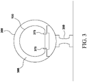
- FIG. 3 shows a cross section of a tube 300 and a capsule 100 within the tube in accordance with an embodiment.
- Tube 300 is supported by a plurality of pylons 350.
- Tube 300 may be above-ground or underground.
- At least a portion of capsule 100 has a rounded, curved exterior surface.
- the side and top of capsule may have a rounded, curved form.
- the surface may have a circular, semi-circular, oval, or other type of rounded surface.
- An interior 308 of tube 300 is maintained at a vacuum or at low pressure. Capsule 100 moves through tube 300 using magnetic levitation technology.
- Capsule 100 has wheels 375. Wheels 375 are unused when capsule 100 is powered magnetic levitation. When magnetic levitation is not used, capsule 100 may use wheels 375. For example, in one embodiment, magnetic levitation is used at speeds above about 20 miles per hour, and wheels are used at speeds below about 20 miles per hour. For example, magnetic levitation may be used between stations, while wheels 375 may be used when capsule 100 is at or near a station.
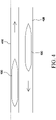
- a first tube 410 is positioned next to a second tube 420.
- First tube 410 carries traffic in a first direction.
- Second tube 420 carries traffic in the opposite direction.
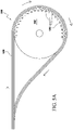
- FIG. 5A shows a station having a loop configuration in accordance with an embodiment.
- Station 500 includes a plurality of tracks 520, a platform 542, and a plurality of gate areas 530.
- Platform 542 may be have a circular, semi-circular, oval, or other round shape. Platform 542 has a rounded edge adjacent to tube 590.
- Tracks 520 enter the station from one side of the station, with traffic moving toward the station, follow a loop around an edge of platform 542, and exit the station on the same side from which they entered, but with traffic moving away from the station.
- the gate areas 530 are numbered 1-22.
- FIG. 5B shows a portion of station 500 in greater detail in accordance with an embodiment.
- FIG. 5B shows gate areas 4 and 5 and the tracks adjacent thereto.
- a tube 590 containing tracks 520 loops around platform 542.
- a low-pressure environment (which may be a vacuum) is maintained within tube 590.
- Gates 535 disposed in a side of tube 590 provide passage from platform 542 into tube 590.
- tube 590 contains three tracks 520; however, in other embodiments, a tube may contain more than three tracks.
- Gates are arranged in pairs. The distance between a pair of gates corresponds to the distance d equal to the distance between doors of a capsule 100. This arrangement allows easy docking, boarding, and deboarding by passengers. For example, in the illustrative embodiment of FIG. 5B , a capsule 100 is docked at gates 535 in gate area 4.
- selected gates are designated as arrival gates and other selected gates are designated as departure gates.
- gates 535 may be designated as arrival gates while other gates may be designated as departure gates.
- each gate serves to connect the environment of the platform 542 with the pressurized environment within the capsule. Accordingly, each gate includes a docking mechanism adapted to produce a sealed connection with the docked capsule, and multiple doors or gates for safety.
- the loop configuration of station 500 advantageously allows capsules to approach the station, stop at a gate area, and then depart in the same direction, without the need to turn around.
- the portion of tube 590 carrying departing capsules may be disposed next to the portion of the tube carrying incoming capsules. This facilitates a continuous, uninterrupted flow of traffic into and out of the station.
- FIG. 5C shows a tube, a gate, and a platform in accordance with an embodiment.
- Tube 590 contains three or more tracks 511.
- Tube 590 contains a low-pressure environment (which may be a vacuum).
- Platform 542 is a platform adapted to hold a plurality of people who may be waiting for a capsule, or who may be leaving a capsule.
- the environment on platform 542 is either an ambient environment open to the outside or a controlled indoor environment such as that of a train station.
- Gate 535 includes two doors 572, 574, which provide a barrier between the low-pressure environment of tube 590 and the environment of platform 542.
- Door 574 opens onto platform 542.
- Gate 535 includes a docking mechanism 568 having a curved surface 569 adapted to conform to the exterior surface of a capsule. Docking mechanism 568 is mounted on an extendable component 567 that has a retracted position (shown in FIG. 5B ) and an extended position.
- FIG. 5D shows capsule 100 docked at gate 535 in accordance with an embodiment.
- Capsule 100 is within tube 590 and is docked at gate 535.
- Docking mechanism 568 is in contact with the exterior surface of capsule 100 and forms a seal with the outer surface of capsule 100. After docking mechanism 568 has formed a seal with the exterior surface of capsule 100, the door(s) of capsule 100 may open and people may pass between platform 542 and the interior of capsule 100.
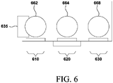
- FIG. 6 shows a three-track configuration in accordance with the invention .
- Docking track 610 is used for docking.
- capsule 662 is docked at gateway 635.
- Express track 630 is used as an express track.
- capsule 668 is moving in the express track without interruption.
- Maneuvering track 620 is used for capsules that malfunction. Such capsules, such as capsule 664, are moved to a maintenance facility for repair.
- three tracks are disposed within a single tube, such as tube 300.
- FIG. 7 shows a capsule 100 docked at a pair of gates 735 in accordance with an embodiment.
- Capsule 100 is in docking track 610.
- Maneuvering track 620 is adjacent docking track 610; express track 630 is adjacent maneuvering track 620.
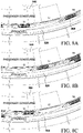
- FIG. 8A-8C shows movement of a plurality of capsules on tracks in a station in accordance with an embodiment.
- a capsule in the docking track such as capsule 850 shown FIG. 8A , changes tracks based on a tangent line method.
- a circle is determined based on the track in which the capsule is currently positioned.
- a circle may be determined based on the curvature of the docking track in which capsule 850 is located.
- a point representing the center of capsule 850 is identified; the point also lies on the circle.
- a tangent line intersecting the circle at the center point of capsule 850 is determined.
- the capsule follows the tangent line until the capsule is in the desired second track.
- a similar tangent line method may be used to determine a trajectory for capsule 870 in FIG. 8B and a trajectory for capsule 880 in FIG. 8C , for example.
- a method of transporting people is provided.
- a capsule adapted to hold a plurality of people is moved through a tube using magnetic levitation.
- the capsule docks at a gate disposed in a side of the tube.
- a component of the gate is caused to form a seal with a surface of the capsule.
- a door is opened in the gate, and people are allowed to enter the capsule. People may also leave the capsule.
- a station for a hyperloop transportation system includes a platform adapted to hold a plurality of people waiting to enter a hyperloop capsule, the platform having a rounded shape with a rounded edge, a tube comprising a low-pressure environment, and a plurality of tracks disposed within the tube, each of the tracks being adapted to carry a hyperloop capsule.
- the tube enters the station on a side of the station, carrying capsule traffic moving toward the station, follows a path around the rounded edge of the platform, and exits the station on the same side of the station on which the tube enters, carrying capsule traffic moving away from the station.
- the station also includes a plurality of gates disposed in one side of the tube, each gate comprising a door forming a barrier between the low-pressure environment of the tube and an exterior of the tube, and a sealing mechanism adapted to form a seal with a hyperloop capsule.
- the station includes three tracks within the tube.
- the station includes the following three tracks: a first track for use by capsules docking at one or more gates, a second track for use by malfunctioning capsules, and a third track for express movement.
- the low-pressure environment within the tube is a vacuum.
- each gate includes first and second doors forming a barrier between the low-pressure environment of the tube and an exterior of the tube, and a sealing mechanism adapted to form a seal with a hyperloop capsule.
- the sealing mechanism includes a component having a curved surface that conforms to the shape of the exterior surface of the hyperloop capsule.
- a method of transporting people is provided.
- a capsule adapted to hold a plurality of people is moved through a tube using magnetic levitation.
- the capsule docks at a gate disposed in a side of the tube.
- a component of the gate is caused to form a seal with a surface of the capsule.
- a door is opened in the gate, and people are allowed to enter the capsule.
Landscapes
- Engineering & Computer Science (AREA)
- Mechanical Engineering (AREA)
- Transportation (AREA)
- Physics & Mathematics (AREA)
- Electromagnetism (AREA)
- Power Engineering (AREA)
- Architecture (AREA)
- Civil Engineering (AREA)
- Structural Engineering (AREA)
- Platform Screen Doors And Railroad Systems (AREA)
- Control Of Vehicles With Linear Motors And Vehicles That Are Magnetically Levitated (AREA)
- Emergency Lowering Means (AREA)
- Small-Scale Networks (AREA)
Description
- Terrestrial passenger and freight travel still rely on modes of transportation developed in the nineteenth and early twentieth centuries. A person wishing to travel long distances over land is limited to using an automobile or a train. Freight transport faces the same limitations. Although high speed trains can now travel more than 300 miles per hour, travelling by either automobile or train is still far slower than travel by air. There is a need for improved and faster modes of terrestrial transportation. Examples of high speed transportation systems can be found for instance in
CN 103818267 orUS 2013/136546 . - The invention is defined by the appended independent claims. Dependent claims constitute embodiments of the invention.
- In accordance with the invention, a station for a hyperloop transportation system is provided. The station includes a platform adapted to hold a plurality of people waiting to enter a hyperloop capsule, the platform having a rounded shape with a rounded edge, a tube comprising a low-pressure environment, and a plurality of tracks disposed within the tube, each of the tracks being adapted to carry a hyperloop capsule. The tube enters the station on a side of the station, carrying capsule traffic moving toward the station, follows a path around the rounded edge of the platform, and exits the station on the same side of the station on which the tube enters, carrying capsule traffic moving away from the station. The station also includes a plurality of gates disposed in one side of the tube, each gate comprising a door forming a barrier between the low-pressure environment of the tube and an exterior of the tube, and a sealing mechanism adapted to form a seal with a hyperloop capsule.
- The station includes three tracks within the tube.
- The station includes the following three tracks: a first track for use by capsules docking at one or more gates, a second track for use by malfunctioning capsules, and a third track for express movement.
- In one embodiment, the low-pressure environment within the tube is a vacuum.
- In another embodiment, each gate includes first and second doors forming a barrier between the low-pressure environment of the tube and an exterior of the tube, and a sealing mechanism adapted to form a seal with a hyperloop capsule.
- In another embodiment, the sealing mechanism includes a component having a curved surface that conforms to the shape of the exterior surface of the hyperloop capsule.
- In accordance with another embodiment, a method of transporting people is provided. A capsule adapted to hold a plurality of people is moved through a tube using magnetic levitation. The capsule docks at a gate disposed in a side of the tube. A component of the gate is caused to form a seal with a surface of the capsule. A door is opened in the gate, and people are allowed to enter the capsule.
-
-
FIG. 1 shows a capsule ; -
FIG. 2 shows the interior of a capsule ; -
FIG. 3 shows a cross section of a tube and a capsule within the tube in accordance with an embodiment; -
FIG. 4 shows a first tube positioned next to a second tube in accordance with an embodiment; -
FIG. 5A shows a station having a loop configuration in accordance with an embodiment; -
FIG. 5B shows a portion of a station in accordance with an embodiment; -
FIG. 5C shows a tube, a gate, and a platform in accordance with an embodiment; -
FIG. 5D shows a capsule docked at a gate in accordance with an embodiment; -
FIG. 6 shows a three-track configuration in accordance with the invention; -
FIG. 7 shows a capsule docked at a pair of gates in accordance with an embodiment; and -
FIG. 8A-8C shows movement of capsules on tracks in a station in accordance with the invention . - A hyperloop system is a mode of passenger and freight transportation that propels a capsule-like vehicle through a reduced-pressure tube that would exceed airliner speed. The capsules accelerate to cruising speed gradually using a linear electric motor and glide above their track using passive magnetic levitation. The tubes can go above ground on columns or underground, eliminating the dangers of grade crossings. The system is highly energy-efficient, quiet and autonomous.
- In accordance with an embodiment, a hyperloop system includes one or more tubes and one or more capsules adapted to travel through the tubes.
-
FIG. 1 shows a capsule Capsule 100 has a length of about 26 meters; however, other lengths may be used. -
FIG. 2 shows the interior of a capsule Capsule 100 has twodoors 250 disposed on one side of the capsule. The distance d from the center of afirst door 250 to the center of thesecond door 250 is 8.311 meters. Other distances may be used. - Capsule 100 contains a plurality of
seats 120. Capsule 100 contains thirty (30) seats. Capsule 100 has anaisle 140; each row includes a single seat disposed on one side ofaisle 140 and two seats disposed on the other side ofaisle 140. - Capsule 100 may include more or fewer than thirty (30) seats. For example, a capsule may have up to one hundred (100) seats and thus may hold up to one hundred persons.
-
FIG. 3 shows a cross section of atube 300 and acapsule 100 within the tube in accordance with an embodiment. Tube 300 is supported by a plurality ofpylons 350. Tube 300 may be above-ground or underground. - At least a portion of
capsule 100 has a rounded, curved exterior surface. For example, the side and top of capsule may have a rounded, curved form. The surface may have a circular, semi-circular, oval, or other type of rounded surface. - An interior 308 of
tube 300 is maintained at a vacuum or at low pressure. Capsule 100 moves throughtube 300 using magnetic levitation technology. - Capsule 100 has
wheels 375.Wheels 375 are unused whencapsule 100 is powered magnetic levitation. When magnetic levitation is not used,capsule 100 may usewheels 375. For example, in one embodiment, magnetic levitation is used at speeds above about 20 miles per hour, and wheels are used at speeds below about 20 miles per hour. For example, magnetic levitation may be used between stations, whilewheels 375 may be used whencapsule 100 is at or near a station. - In accordance with an embodiment shown in
FIG. 4 , afirst tube 410 is positioned next to asecond tube 420.First tube 410 carries traffic in a first direction.Second tube 420 carries traffic in the opposite direction. - In accordance with an embodiment, passengers board capsules and exit capsules at a station.
FIG. 5A shows a station having a loop configuration in accordance with an embodiment.Station 500 includes a plurality oftracks 520, aplatform 542, and a plurality ofgate areas 530.Platform 542 may be have a circular, semi-circular, oval, or other round shape.Platform 542 has a rounded edge adjacent totube 590.Tracks 520 enter the station from one side of the station, with traffic moving toward the station, follow a loop around an edge ofplatform 542, and exit the station on the same side from which they entered, but with traffic moving away from the station. In the illustrative embodiment, thegate areas 530 are numbered 1-22. -
Fig. 5B shows a portion ofstation 500 in greater detail in accordance with an embodiment. In particular,FIG. 5B showsgate areas tube 590 containingtracks 520 loops aroundplatform 542. A low-pressure environment (which may be a vacuum) is maintained withintube 590.Gates 535 disposed in a side oftube 590 provide passage fromplatform 542 intotube 590. - In the illustrative embodiment of
FIG. 5A ,tube 590 contains threetracks 520; however, in other embodiments, a tube may contain more than three tracks. - Gates are arranged in pairs. The distance between a pair of gates corresponds to the distance d equal to the distance between doors of a
capsule 100. This arrangement allows easy docking, boarding, and deboarding by passengers. For example, in the illustrative embodiment ofFIG. 5B , acapsule 100 is docked atgates 535 ingate area 4. - In one embodiment, selected gates are designated as arrival gates and other selected gates are designated as departure gates. For example, in the illustrative embodiment of
FIG. 5B ,gates 535 may be designated as arrival gates while other gates may be designated as departure gates. - When a capsule docks at
gate 535, the gates serves to connect the environment of theplatform 542 with the pressurized environment within the capsule. Accordingly, each gate includes a docking mechanism adapted to produce a sealed connection with the docked capsule, and multiple doors or gates for safety. - The loop configuration of
station 500 advantageously allows capsules to approach the station, stop at a gate area, and then depart in the same direction, without the need to turn around. For example, referring again toFIG. 5A , the portion oftube 590 carrying departing capsules may be disposed next to the portion of the tube carrying incoming capsules. This facilitates a continuous, uninterrupted flow of traffic into and out of the station. -
FIG. 5C shows a tube, a gate, and a platform in accordance with an embodiment.Tube 590 contains three or more tracks 511.Tube 590 contains a low-pressure environment (which may be a vacuum).Platform 542 is a platform adapted to hold a plurality of people who may be waiting for a capsule, or who may be leaving a capsule. The environment onplatform 542 is either an ambient environment open to the outside or a controlled indoor environment such as that of a train station.Gate 535 includes twodoors tube 590 and the environment ofplatform 542.Door 574 opens ontoplatform 542. -
Gate 535 includes adocking mechanism 568 having a curved surface 569 adapted to conform to the exterior surface of a capsule.Docking mechanism 568 is mounted on anextendable component 567 that has a retracted position (shown inFIG. 5B ) and an extended position. - Referring to
FIG. 5D , when a capsule arrives atgate 535,extendable component 567 expands and extends away from the side oftube 590, causingdocking mechanism 568 to contact the exterior surface ofcapsule 100 and to form a seal with the surface of the capsule.FIG. 5D showscapsule 100 docked atgate 535 in accordance with an embodiment.Capsule 100 is withintube 590 and is docked atgate 535.Docking mechanism 568 is in contact with the exterior surface ofcapsule 100 and forms a seal with the outer surface ofcapsule 100. After dockingmechanism 568 has formed a seal with the exterior surface ofcapsule 100, the door(s) ofcapsule 100 may open and people may pass betweenplatform 542 and the interior ofcapsule 100. - Three tracks are used at or near a station.
FIG. 6 shows a three-track configuration in accordance with the invention .Docking track 610 is used for docking. Thus,capsule 662 is docked atgateway 635.Express track 630 is used as an express track. Thuscapsule 668 is moving in the express track without interruption.Maneuvering track 620 is used for capsules that malfunction. Such capsules, such ascapsule 664, are moved to a maintenance facility for repair. - Within a predetermined distance from a station, three tracks are disposed within a single tube, such as
tube 300. -
FIG. 7 shows acapsule 100 docked at a pair ofgates 735 in accordance with an embodiment.Capsule 100 is indocking track 610.Maneuvering track 620 isadjacent docking track 610;express track 630 isadjacent maneuvering track 620. -
FIG. 8A-8C shows movement of a plurality of capsules on tracks in a station in accordance with an embodiment. A capsule in the docking track, such ascapsule 850 shownFIG. 8A , changes tracks based on a tangent line method. A circle is determined based on the track in which the capsule is currently positioned. Thus, referring toFIG. 8A , a circle may be determined based on the curvature of the docking track in whichcapsule 850 is located. A point representing the center ofcapsule 850 is identified; the point also lies on the circle. A tangent line intersecting the circle at the center point ofcapsule 850 is determined. When capsule leaves the docking track in order to move to a second track, the capsule follows the tangent line until the capsule is in the desired second track. A similar tangent line method may be used to determine a trajectory for capsule 870 inFIG. 8B and a trajectory for capsule 880 inFIG. 8C , for example. - In accordance with another embodiment, a method of transporting people is provided. A capsule adapted to hold a plurality of people is moved through a tube using magnetic levitation. The capsule docks at a gate disposed in a side of the tube. A component of the gate is caused to form a seal with a surface of the capsule. A door is opened in the gate, and people are allowed to enter the capsule. People may also leave the capsule.
- In accordance with an embodiment, a station for a hyperloop transportation system is provided. The station includes a platform adapted to hold a plurality of people waiting to enter a hyperloop capsule, the platform having a rounded shape with a rounded edge, a tube comprising a low-pressure environment, and a plurality of tracks disposed within the tube, each of the tracks being adapted to carry a hyperloop capsule. The tube enters the station on a side of the station, carrying capsule traffic moving toward the station, follows a path around the rounded edge of the platform, and exits the station on the same side of the station on which the tube enters, carrying capsule traffic moving away from the station. The station also includes a plurality of gates disposed in one side of the tube, each gate comprising a door forming a barrier between the low-pressure environment of the tube and an exterior of the tube, and a sealing mechanism adapted to form a seal with a hyperloop capsule.
- The station includes three tracks within the tube.
- The station includes the following three tracks: a first track for use by capsules docking at one or more gates, a second track for use by malfunctioning capsules, and a third track for express movement.
- In another embodiment, the low-pressure environment within the tube is a vacuum.
- In another embodiment, each gate includes first and second doors forming a barrier between the low-pressure environment of the tube and an exterior of the tube, and a sealing mechanism adapted to form a seal with a hyperloop capsule.
- In another embodiment, the sealing mechanism includes a component having a curved surface that conforms to the shape of the exterior surface of the hyperloop capsule.
- In accordance with another embodiment, a method of transporting people is provided. A capsule adapted to hold a plurality of people is moved through a tube using magnetic levitation. The capsule docks at a gate disposed in a side of the tube. A component of the gate is caused to form a seal with a surface of the capsule. A door is opened in the gate, and people are allowed to enter the capsule.
- The foregoing Detailed Description is to be understood as being in every respect illustrative and exemplary, but not restrictive, and the scope of the invention disclosed herein is not to be determined from the Detailed Description, but rather from the claims as interpreted according to the full breadth permitted by the patent laws. It is to be understood that the embodiments shown and described herein are only illustrative of the principles of the present invention and that various modifications may be implemented by those skilled in the art without departing from the scope of the invention. Those skilled in the art could implement various other feature combinations without departing from the scope of the invention.
Claims (5)
- A station (500) for a hyperloop transportation system comprising:a platform (542) adapted to hold a plurality of people waiting to enter a hyperloop capsule (100), the platform (542) having a rounded shape with a rounded edge;a tube (300) comprising a low-pressure environment;a plurality of gates (530) disposed in one side of the tube (300), each gate (1-22) comprising a door forming a barrier between the low-pressure environment of the tube (300) and an exterior of the tube (300), and a sealing mechanism (568) adapted to form a seal with a hyperloop capsule (100); anda plurality of tracks (520) disposed within the tube (300), each of the tracks (520) being adapted to carry a hyperloop capsule (100), the plurality of tracks (520) comprising:a first track (610) for use by capsules (100) docking at one or more gates (530);a second track (620) for use by malfunctioning capsules (100); anda third track (630) for express movement;wherein the tube (300) enters the station (500) on a side of the station (500), carrying capsule traffic moving toward the station (500), follows a path around the rounded edge of the platform (542), and exits the station (500) on the same side of the station (500) on which the tube (300) enters, carrying capsule traffic moving away from the station (500).
- The station (500) of claim 1, wherein the low-pressure environment is a vacuum.
- The station (500) of claim 1, wherein each gate (535) comprises:first and second doors (572, 574) forming a barrier between the low-pressure environment of the tube (590) and an exterior of the tube (590); anda sealing mechanism (568) adapted to form a seal with a hyperloop capsule (100).
- The station (500) of claim 3, wherein the sealing mechanism (568) is a component having a curved surface that conforms to the shape of the exterior surface of the hyperloop capsule (100).
- A method of transporting people at a station (500) according to claim 1, the method comprising:moving a capsule (100) adapted to hold a plurality of people on a selected track (520) through a tube (300) using magnetic levitation, said tube (300) comprising a plurality of tracks (520) disposed within the tube (300), each of the tracks (520) being adapted to carry a hyperloop capsule (100), the plurality of tracks (520) comprising a first track (610) for use by capsules (100) docking at one or more gates (530), a second track (620) for use by malfunctioning capsules (100), and a third track (630) for express movement;moving the capsule (100) to the first track (610) when the capsule (100) approaches a gate (1-22) disposed in a side of the tube (300)docking the capsule (100) at the gate (535), while the capsule (100) is on the first track (610);causing a component of the gate to form a seal (568) with a surface of the capsule (100);opening a door in the gate (535);allowing people to enter the capsule (100);moving the capsule (100) to the third track (630); andmoving the capsule (100) in an express movement mode, while the capsule (100) is on the third track (630).
Applications Claiming Priority (2)
| Application Number | Priority Date | Filing Date | Title |
|---|---|---|---|
| US201662339069P | 2016-05-19 | 2016-05-19 | |
| PCT/US2017/033589 WO2017201435A1 (en) | 2016-05-19 | 2017-05-19 | Station with loop configuration for hyperloop transportation system |
Publications (3)
| Publication Number | Publication Date |
|---|---|
| EP3458328A1 EP3458328A1 (en) | 2019-03-27 |
| EP3458328A4 EP3458328A4 (en) | 2020-01-22 |
| EP3458328B1 true EP3458328B1 (en) | 2022-04-13 |
Family
ID=60326150
Family Applications (1)
| Application Number | Title | Priority Date | Filing Date |
|---|---|---|---|
| EP17800259.8A Active EP3458328B1 (en) | 2016-05-19 | 2017-05-19 | Station with loop configuration for hyperloop transportation system |
Country Status (5)
| Country | Link |
|---|---|
| US (1) | US10493859B2 (en) |
| EP (1) | EP3458328B1 (en) |
| CN (1) | CN109311484A (en) |
| ES (1) | ES2920147T3 (en) |
| WO (1) | WO2017201435A1 (en) |
Families Citing this family (19)
| Publication number | Priority date | Publication date | Assignee | Title |
|---|---|---|---|---|
| WO2017201435A1 (en) * | 2016-05-19 | 2017-11-23 | Hyperloop Transportation Technologies, Inc. | Station with loop configuration for hyperloop transportation system |
| US11319098B2 (en) * | 2017-03-31 | 2022-05-03 | The Boeing Company | Vacuum volume reduction system and method with fluid fill assembly for a vacuum tube vehicle station |
| US10220972B2 (en) * | 2017-03-31 | 2019-03-05 | The Boeing Company | Vacuum volume reduction system and method for a vacuum tube vehicle station |
| CN108860170B (en) * | 2018-03-19 | 2020-04-21 | 武汉理工大学 | A vacuum pipeline maglev train vacuum connection system |
| NL2021603B1 (en) * | 2018-09-11 | 2020-05-01 | Hardt Ip B V | Airlock arrangement for a transportation system |
| GB201904827D0 (en) * | 2018-11-14 | 2019-05-22 | Ocado Innovation Ltd | Container-manoeuvring apparatus |
| CN110281985B (en) * | 2019-03-19 | 2021-06-08 | 卡斯柯信号有限公司 | An ultra-high-speed maglev train operation control system and method |
| US10835832B2 (en) * | 2019-03-31 | 2020-11-17 | Universal City Studio LLC | Gap covering systems and methods for amusement park attractions |
| US12539889B2 (en) | 2019-08-27 | 2026-02-03 | Universal City Studios Llc | Gate systems and methods for rotating loading platform |
| CN110641481A (en) * | 2019-09-06 | 2020-01-03 | 张晓华 | A station system for dynamic getting on and off |
| CN112626936B (en) * | 2019-09-24 | 2022-08-09 | 中国航天科工飞航技术研究院(中国航天海鹰机电技术研究院) | Double-line track beam with metal belt and single-pipe double-line vacuum pipeline |
| ES2827898B2 (en) * | 2019-10-08 | 2025-02-12 | Zeleros Global S L | MATRIX ELECTROMAGNETIC SUSPENSION SYSTEM FOR TRANSPORT VEHICLES |
| US11518417B2 (en) | 2020-02-14 | 2022-12-06 | Safran Landing Systems | Wheeled vehicle station docking using a kneeling landing gear system |
| CN115916618A (en) * | 2020-04-30 | 2023-04-04 | 超级高铁技术公司 | Pod compartment and vehicle docking |
| CN111594627B (en) * | 2020-05-06 | 2024-07-02 | 中国空气动力研究与发展中心超高速空气动力研究所 | Thermal valve and manufacturing method thereof |
| CN112373525B (en) * | 2020-11-27 | 2021-12-31 | 同济大学 | Arrangement method for magnetic suspension traffic auxiliary parking area |
| US20220212887A1 (en) * | 2021-01-05 | 2022-07-07 | Hyperloop Technologies, Inc. | System and Method for an Inland Port Using Hyperloop |
| US12186600B2 (en) * | 2021-03-16 | 2025-01-07 | B/E Aerospace, Inc. | Low pressure enclosure vehicles having supplemental oxygen systems |
| WO2024127425A1 (en) * | 2022-12-13 | 2024-06-20 | INDIAN INSTITUTE OF TECHNOLOGY MADRAS (IIT Madras) | Hyperloop transportation system |
Family Cites Families (22)
| Publication number | Priority date | Publication date | Assignee | Title |
|---|---|---|---|---|
| US3865041A (en) * | 1973-04-16 | 1975-02-11 | Arrow Dev Co | Rotary platform vehicle passenger loading system |
| CN1417073A (en) * | 2002-12-02 | 2003-05-14 | 张惠东 | Road network and traffic tool system |
| CN100543271C (en) * | 2006-06-13 | 2009-09-23 | 上海市隧道工程轨道交通设计研究院 | Magnetic suspension tunnel internal zone dividing method |
| CN1861907A (en) * | 2006-06-13 | 2006-11-15 | 上海市隧道工程轨道交通设计研究院 | Installing method of magnetic suspension rail beam in tunnel |
| CN101327798B (en) * | 2007-06-22 | 2011-02-02 | 刘本林 | Method of vacuum pipelines for long-distance passenger transport |
| CN101823488A (en) * | 2009-03-03 | 2010-09-08 | 刘忠臣 | Vacuum pipeline docking technology and high-speed permanent maglev train system |
| CN103818267B (en) | 2010-03-03 | 2016-07-06 | 大连奇想科技有限公司 | The docking system of train and station passage |
| CN102145698A (en) * | 2010-11-15 | 2011-08-10 | 重庆兆迈机械技术研发有限公司 | Translation and rail transfer system of magnetic suspension train |
| CN101992782A (en) * | 2010-12-02 | 2011-03-30 | 张婧 | Urban unmanned electronic railcar taxi traffic system |
| AU2011342364B2 (en) * | 2010-12-16 | 2016-09-29 | David Dalrymple | An evacuated tube transport system |
| US8584593B2 (en) * | 2011-07-28 | 2013-11-19 | Jan Friedmann | Aquatic and terrestrial trans-web infrastructure network system (T.W.I.N.S.) |
| CN104057962A (en) * | 2013-03-23 | 2014-09-24 | 何筱钦 | Vacuum and supersonic maglev double lanes |
| US20160121908A1 (en) * | 2013-05-01 | 2016-05-05 | Othman Bin Ahmad | Zero energy transportation system |
| CN103523023B (en) * | 2013-10-25 | 2016-06-22 | 芦定军 | Solar rail unit, road networked system and energy utilizing method thereof and passenger management method |
| EP3253636B1 (en) * | 2015-02-08 | 2021-05-12 | Hyperloop Technologies, Inc. | Transportation system |
| US9566987B2 (en) * | 2015-02-08 | 2017-02-14 | Hyperloop Technologies, Inc. | Low-pressure environment structures |
| CN107466444B (en) * | 2015-02-08 | 2019-05-17 | 超级高铁技术公司 | Dynamic Linear Stator Segment Control |
| US9599235B2 (en) * | 2015-02-08 | 2017-03-21 | Hyperloop Technologies, Inc. | Gate valves and airlocks for a transportation system |
| CN105523046B (en) * | 2016-01-28 | 2018-05-08 | 张晓华 | A kind of closed transportation system |
| CN105539499A (en) * | 2016-02-03 | 2016-05-04 | 张晓华 | No-parking passenger getting-on and getting-off system |
| CN105564443A (en) * | 2016-03-10 | 2016-05-11 | 北京九州动脉隧道技术有限公司 | Rotation type station used for vacuum environment |
| WO2017201435A1 (en) * | 2016-05-19 | 2017-11-23 | Hyperloop Transportation Technologies, Inc. | Station with loop configuration for hyperloop transportation system |
-
2017
- 2017-05-19 WO PCT/US2017/033589 patent/WO2017201435A1/en not_active Ceased
- 2017-05-19 ES ES17800259T patent/ES2920147T3/en active Active
- 2017-05-19 US US15/600,189 patent/US10493859B2/en active Active
- 2017-05-19 EP EP17800259.8A patent/EP3458328B1/en active Active
- 2017-05-19 CN CN201780037572.9A patent/CN109311484A/en active Pending
Also Published As
| Publication number | Publication date |
|---|---|
| CN109311484A (en) | 2019-02-05 |
| ES2920147T3 (en) | 2022-08-01 |
| WO2017201435A1 (en) | 2017-11-23 |
| EP3458328A1 (en) | 2019-03-27 |
| EP3458328A4 (en) | 2020-01-22 |
| US10493859B2 (en) | 2019-12-03 |
| US20170334312A1 (en) | 2017-11-23 |
Similar Documents
| Publication | Publication Date | Title |
|---|---|---|
| US10493859B2 (en) | Station with loop configuration for hyperloop transportation system | |
| CN108313073B (en) | Sectional type vacuum pipeline transportation system and transportation method | |
| US3006288A (en) | System for high-speed transport | |
| US9873439B2 (en) | Cable car system for transporting people | |
| AU2014210672B2 (en) | Cableway system for transporting persons | |
| EP1613813B1 (en) | Station design | |
| CN102361775A (en) | Oxygen-enriched low-pressure pipeline permanent magnet drive wheel-rail maglev vehicle road system | |
| US10392030B2 (en) | Aerial cableway system | |
| US20180057028A1 (en) | High Speed Train System | |
| US20100307368A1 (en) | Motion connection parallel transit | |
| CN101152866A (en) | System for ultrahigh speed railway train running in vacuum tunnel (pipeline) | |
| CN103465912A (en) | Constant-speed surround transmission system | |
| US6102331A (en) | Operation of airports | |
| CN109466567A (en) | A kind of vacuum pipe traffic vehicle | |
| CN105109494A (en) | Rail transportation system and transportation scheme thereof | |
| CN105774816A (en) | Novel high-speed railway passenger transport control system | |
| CN203511638U (en) | Constant-speed surrounding transferring system | |
| CN101830229A (en) | Underground pipeline transportation system | |
| RU2664091C1 (en) | Air train and its travel tracks | |
| RU2205761C1 (en) | Modular transportation system and method of its operation | |
| CN107139937B (en) | A kind of subway system is used as the method and system at vacuum pipe traffic branch line and station | |
| CN213973963U (en) | Low-vacuum pipeline taking-in and taking-off system, running vehicle and transportation system | |
| KR101502565B1 (en) | Personal Rapid Transit Vehicle Vertical Transfer Using Propulsion Device | |
| CN103465913A (en) | Constant-speed surround transmission network | |
| CN203511639U (en) | Constant-speed surrounding transmission network |
Legal Events
| Date | Code | Title | Description |
|---|---|---|---|
| STAA | Information on the status of an ep patent application or granted ep patent |
Free format text: STATUS: THE INTERNATIONAL PUBLICATION HAS BEEN MADE |
|
| PUAI | Public reference made under article 153(3) epc to a published international application that has entered the european phase |
Free format text: ORIGINAL CODE: 0009012 |
|
| STAA | Information on the status of an ep patent application or granted ep patent |
Free format text: STATUS: REQUEST FOR EXAMINATION WAS MADE |
|
| 17P | Request for examination filed |
Effective date: 20181217 |
|
| AK | Designated contracting states |
Kind code of ref document: A1 Designated state(s): AL AT BE BG CH CY CZ DE DK EE ES FI FR GB GR HR HU IE IS IT LI LT LU LV MC MK MT NL NO PL PT RO RS SE SI SK SM TR |
|
| AX | Request for extension of the european patent |
Extension state: BA ME |
|
| DAV | Request for validation of the european patent (deleted) | ||
| DAX | Request for extension of the european patent (deleted) | ||
| A4 | Supplementary search report drawn up and despatched |
Effective date: 20200102 |
|
| RIC1 | Information provided on ipc code assigned before grant |
Ipc: B61B 13/08 20060101ALI20191217BHEP Ipc: B60L 13/10 20060101ALI20191217BHEP Ipc: B61B 1/00 20060101AFI20191217BHEP Ipc: B60L 13/00 20060101ALI20191217BHEP Ipc: B61B 1/02 20060101ALI20191217BHEP Ipc: E01B 25/30 20060101ALI20191217BHEP Ipc: B61B 13/10 20060101ALI20191217BHEP Ipc: B61L 25/02 20060101ALN20191217BHEP |
|
| GRAP | Despatch of communication of intention to grant a patent |
Free format text: ORIGINAL CODE: EPIDOSNIGR1 |
|
| STAA | Information on the status of an ep patent application or granted ep patent |
Free format text: STATUS: GRANT OF PATENT IS INTENDED |
|
| RIC1 | Information provided on ipc code assigned before grant |
Ipc: B61B 1/00 20060101AFI20210702BHEP Ipc: B61B 13/10 20060101ALI20210702BHEP Ipc: B61B 13/08 20060101ALI20210702BHEP Ipc: B60L 13/00 20060101ALI20210702BHEP Ipc: B60L 13/10 20060101ALI20210702BHEP Ipc: E01B 25/30 20060101ALI20210702BHEP Ipc: B61B 1/02 20060101ALI20210702BHEP Ipc: B61L 25/02 20060101ALN20210702BHEP |
|
| RIC1 | Information provided on ipc code assigned before grant |
Ipc: B61B 1/00 20060101AFI20210713BHEP Ipc: B61B 13/10 20060101ALI20210713BHEP Ipc: B61B 13/08 20060101ALI20210713BHEP Ipc: B60L 13/00 20060101ALI20210713BHEP Ipc: B60L 13/10 20060101ALI20210713BHEP Ipc: E01B 25/30 20060101ALI20210713BHEP Ipc: B61B 1/02 20060101ALI20210713BHEP Ipc: B61L 25/02 20060101ALN20210713BHEP |
|
| INTG | Intention to grant announced |
Effective date: 20210727 |
|
| GRAS | Grant fee paid |
Free format text: ORIGINAL CODE: EPIDOSNIGR3 |
|
| GRAA | (expected) grant |
Free format text: ORIGINAL CODE: 0009210 |
|
| STAA | Information on the status of an ep patent application or granted ep patent |
Free format text: STATUS: THE PATENT HAS BEEN GRANTED |
|
| AK | Designated contracting states |
Kind code of ref document: B1 Designated state(s): AL AT BE BG CH CY CZ DE DK EE ES FI FR GB GR HR HU IE IS IT LI LT LU LV MC MK MT NL NO PL PT RO RS SE SI SK SM TR |
|
| REG | Reference to a national code |
Ref country code: GB Ref legal event code: FG4D |
|
| REG | Reference to a national code |
Ref country code: CH Ref legal event code: EP |
|
| REG | Reference to a national code |
Ref country code: DE Ref legal event code: R096 Ref document number: 602017055979 Country of ref document: DE |
|
| REG | Reference to a national code |
Ref country code: IE Ref legal event code: FG4D |
|
| REG | Reference to a national code |
Ref country code: AT Ref legal event code: REF Ref document number: 1483193 Country of ref document: AT Kind code of ref document: T Effective date: 20220515 |
|
| REG | Reference to a national code |
Ref country code: ES Ref legal event code: FG2A Ref document number: 2920147 Country of ref document: ES Kind code of ref document: T3 Effective date: 20220801 |
|
| REG | Reference to a national code |
Ref country code: LT Ref legal event code: MG9D |
|
| REG | Reference to a national code |
Ref country code: NL Ref legal event code: MP Effective date: 20220413 |
|
| REG | Reference to a national code |
Ref country code: AT Ref legal event code: MK05 Ref document number: 1483193 Country of ref document: AT Kind code of ref document: T Effective date: 20220413 |
|
| PG25 | Lapsed in a contracting state [announced via postgrant information from national office to epo] |
Ref country code: NL Free format text: LAPSE BECAUSE OF FAILURE TO SUBMIT A TRANSLATION OF THE DESCRIPTION OR TO PAY THE FEE WITHIN THE PRESCRIBED TIME-LIMIT Effective date: 20220413 |
|
| PGFP | Annual fee paid to national office [announced via postgrant information from national office to epo] |
Ref country code: FR Payment date: 20220616 Year of fee payment: 7 |
|
| PG25 | Lapsed in a contracting state [announced via postgrant information from national office to epo] |
Ref country code: SE Free format text: LAPSE BECAUSE OF FAILURE TO SUBMIT A TRANSLATION OF THE DESCRIPTION OR TO PAY THE FEE WITHIN THE PRESCRIBED TIME-LIMIT Effective date: 20220413 Ref country code: PT Free format text: LAPSE BECAUSE OF FAILURE TO SUBMIT A TRANSLATION OF THE DESCRIPTION OR TO PAY THE FEE WITHIN THE PRESCRIBED TIME-LIMIT Effective date: 20220816 Ref country code: NO Free format text: LAPSE BECAUSE OF FAILURE TO SUBMIT A TRANSLATION OF THE DESCRIPTION OR TO PAY THE FEE WITHIN THE PRESCRIBED TIME-LIMIT Effective date: 20220713 Ref country code: LT Free format text: LAPSE BECAUSE OF FAILURE TO SUBMIT A TRANSLATION OF THE DESCRIPTION OR TO PAY THE FEE WITHIN THE PRESCRIBED TIME-LIMIT Effective date: 20220413 Ref country code: HR Free format text: LAPSE BECAUSE OF FAILURE TO SUBMIT A TRANSLATION OF THE DESCRIPTION OR TO PAY THE FEE WITHIN THE PRESCRIBED TIME-LIMIT Effective date: 20220413 Ref country code: GR Free format text: LAPSE BECAUSE OF FAILURE TO SUBMIT A TRANSLATION OF THE DESCRIPTION OR TO PAY THE FEE WITHIN THE PRESCRIBED TIME-LIMIT Effective date: 20220714 Ref country code: FI Free format text: LAPSE BECAUSE OF FAILURE TO SUBMIT A TRANSLATION OF THE DESCRIPTION OR TO PAY THE FEE WITHIN THE PRESCRIBED TIME-LIMIT Effective date: 20220413 Ref country code: BG Free format text: LAPSE BECAUSE OF FAILURE TO SUBMIT A TRANSLATION OF THE DESCRIPTION OR TO PAY THE FEE WITHIN THE PRESCRIBED TIME-LIMIT Effective date: 20220713 Ref country code: AT Free format text: LAPSE BECAUSE OF FAILURE TO SUBMIT A TRANSLATION OF THE DESCRIPTION OR TO PAY THE FEE WITHIN THE PRESCRIBED TIME-LIMIT Effective date: 20220413 |
|
| PG25 | Lapsed in a contracting state [announced via postgrant information from national office to epo] |
Ref country code: RS Free format text: LAPSE BECAUSE OF FAILURE TO SUBMIT A TRANSLATION OF THE DESCRIPTION OR TO PAY THE FEE WITHIN THE PRESCRIBED TIME-LIMIT Effective date: 20220413 Ref country code: PL Free format text: LAPSE BECAUSE OF FAILURE TO SUBMIT A TRANSLATION OF THE DESCRIPTION OR TO PAY THE FEE WITHIN THE PRESCRIBED TIME-LIMIT Effective date: 20220413 Ref country code: LV Free format text: LAPSE BECAUSE OF FAILURE TO SUBMIT A TRANSLATION OF THE DESCRIPTION OR TO PAY THE FEE WITHIN THE PRESCRIBED TIME-LIMIT Effective date: 20220413 Ref country code: IS Free format text: LAPSE BECAUSE OF FAILURE TO SUBMIT A TRANSLATION OF THE DESCRIPTION OR TO PAY THE FEE WITHIN THE PRESCRIBED TIME-LIMIT Effective date: 20220813 |
|
| REG | Reference to a national code |
Ref country code: CH Ref legal event code: PL |
|
| REG | Reference to a national code |
Ref country code: DE Ref legal event code: R097 Ref document number: 602017055979 Country of ref document: DE |
|
| REG | Reference to a national code |
Ref country code: BE Ref legal event code: MM Effective date: 20220531 |
|
| PG25 | Lapsed in a contracting state [announced via postgrant information from national office to epo] |
Ref country code: SM Free format text: LAPSE BECAUSE OF FAILURE TO SUBMIT A TRANSLATION OF THE DESCRIPTION OR TO PAY THE FEE WITHIN THE PRESCRIBED TIME-LIMIT Effective date: 20220413 Ref country code: SK Free format text: LAPSE BECAUSE OF FAILURE TO SUBMIT A TRANSLATION OF THE DESCRIPTION OR TO PAY THE FEE WITHIN THE PRESCRIBED TIME-LIMIT Effective date: 20220413 Ref country code: RO Free format text: LAPSE BECAUSE OF FAILURE TO SUBMIT A TRANSLATION OF THE DESCRIPTION OR TO PAY THE FEE WITHIN THE PRESCRIBED TIME-LIMIT Effective date: 20220413 Ref country code: MC Free format text: LAPSE BECAUSE OF FAILURE TO SUBMIT A TRANSLATION OF THE DESCRIPTION OR TO PAY THE FEE WITHIN THE PRESCRIBED TIME-LIMIT Effective date: 20220413 Ref country code: LU Free format text: LAPSE BECAUSE OF NON-PAYMENT OF DUE FEES Effective date: 20220519 Ref country code: LI Free format text: LAPSE BECAUSE OF NON-PAYMENT OF DUE FEES Effective date: 20220531 Ref country code: EE Free format text: LAPSE BECAUSE OF FAILURE TO SUBMIT A TRANSLATION OF THE DESCRIPTION OR TO PAY THE FEE WITHIN THE PRESCRIBED TIME-LIMIT Effective date: 20220413 Ref country code: DK Free format text: LAPSE BECAUSE OF FAILURE TO SUBMIT A TRANSLATION OF THE DESCRIPTION OR TO PAY THE FEE WITHIN THE PRESCRIBED TIME-LIMIT Effective date: 20220413 Ref country code: CZ Free format text: LAPSE BECAUSE OF FAILURE TO SUBMIT A TRANSLATION OF THE DESCRIPTION OR TO PAY THE FEE WITHIN THE PRESCRIBED TIME-LIMIT Effective date: 20220413 Ref country code: CH Free format text: LAPSE BECAUSE OF NON-PAYMENT OF DUE FEES Effective date: 20220531 |
|
| PLBE | No opposition filed within time limit |
Free format text: ORIGINAL CODE: 0009261 |
|
| STAA | Information on the status of an ep patent application or granted ep patent |
Free format text: STATUS: NO OPPOSITION FILED WITHIN TIME LIMIT |
|
| 26N | No opposition filed |
Effective date: 20230116 |
|
| PG25 | Lapsed in a contracting state [announced via postgrant information from national office to epo] |
Ref country code: AL Free format text: LAPSE BECAUSE OF FAILURE TO SUBMIT A TRANSLATION OF THE DESCRIPTION OR TO PAY THE FEE WITHIN THE PRESCRIBED TIME-LIMIT Effective date: 20220413 |
|
| PG25 | Lapsed in a contracting state [announced via postgrant information from national office to epo] |
Ref country code: IE Free format text: LAPSE BECAUSE OF NON-PAYMENT OF DUE FEES Effective date: 20220519 |
|
| PG25 | Lapsed in a contracting state [announced via postgrant information from national office to epo] |
Ref country code: SI Free format text: LAPSE BECAUSE OF FAILURE TO SUBMIT A TRANSLATION OF THE DESCRIPTION OR TO PAY THE FEE WITHIN THE PRESCRIBED TIME-LIMIT Effective date: 20220413 Ref country code: BE Free format text: LAPSE BECAUSE OF NON-PAYMENT OF DUE FEES Effective date: 20220531 |
|
| P01 | Opt-out of the competence of the unified patent court (upc) registered |
Effective date: 20230516 |
|
| PGFP | Annual fee paid to national office [announced via postgrant information from national office to epo] |
Ref country code: IT Payment date: 20230519 Year of fee payment: 7 Ref country code: DE Payment date: 20230530 Year of fee payment: 7 |
|
| PGFP | Annual fee paid to national office [announced via postgrant information from national office to epo] |
Ref country code: GB Payment date: 20230529 Year of fee payment: 7 |
|
| PG25 | Lapsed in a contracting state [announced via postgrant information from national office to epo] |
Ref country code: HU Free format text: LAPSE BECAUSE OF FAILURE TO SUBMIT A TRANSLATION OF THE DESCRIPTION OR TO PAY THE FEE WITHIN THE PRESCRIBED TIME-LIMIT; INVALID AB INITIO Effective date: 20170519 |
|
| PG25 | Lapsed in a contracting state [announced via postgrant information from national office to epo] |
Ref country code: MK Free format text: LAPSE BECAUSE OF FAILURE TO SUBMIT A TRANSLATION OF THE DESCRIPTION OR TO PAY THE FEE WITHIN THE PRESCRIBED TIME-LIMIT Effective date: 20220413 Ref country code: CY Free format text: LAPSE BECAUSE OF FAILURE TO SUBMIT A TRANSLATION OF THE DESCRIPTION OR TO PAY THE FEE WITHIN THE PRESCRIBED TIME-LIMIT Effective date: 20220413 |
|
| PG25 | Lapsed in a contracting state [announced via postgrant information from national office to epo] |
Ref country code: TR Free format text: LAPSE BECAUSE OF FAILURE TO SUBMIT A TRANSLATION OF THE DESCRIPTION OR TO PAY THE FEE WITHIN THE PRESCRIBED TIME-LIMIT Effective date: 20220413 |
|
| PG25 | Lapsed in a contracting state [announced via postgrant information from national office to epo] |
Ref country code: MT Free format text: LAPSE BECAUSE OF FAILURE TO SUBMIT A TRANSLATION OF THE DESCRIPTION OR TO PAY THE FEE WITHIN THE PRESCRIBED TIME-LIMIT Effective date: 20220413 |
|
| PG25 | Lapsed in a contracting state [announced via postgrant information from national office to epo] |
Ref country code: BG Free format text: LAPSE BECAUSE OF FAILURE TO SUBMIT A TRANSLATION OF THE DESCRIPTION OR TO PAY THE FEE WITHIN THE PRESCRIBED TIME-LIMIT Effective date: 20220413 |
|
| PG25 | Lapsed in a contracting state [announced via postgrant information from national office to epo] |
Ref country code: BG Free format text: LAPSE BECAUSE OF FAILURE TO SUBMIT A TRANSLATION OF THE DESCRIPTION OR TO PAY THE FEE WITHIN THE PRESCRIBED TIME-LIMIT Effective date: 20220413 |
|
| REG | Reference to a national code |
Ref country code: DE Ref legal event code: R119 Ref document number: 602017055979 Country of ref document: DE |
|
| PGFP | Annual fee paid to national office [announced via postgrant information from national office to epo] |
Ref country code: ES Payment date: 20241113 Year of fee payment: 8 |
|
| GBPC | Gb: european patent ceased through non-payment of renewal fee |
Effective date: 20240519 |
|
| PG25 | Lapsed in a contracting state [announced via postgrant information from national office to epo] |
Ref country code: DE Free format text: LAPSE BECAUSE OF NON-PAYMENT OF DUE FEES Effective date: 20241203 |
|
| PG25 | Lapsed in a contracting state [announced via postgrant information from national office to epo] |
Ref country code: FR Free format text: LAPSE BECAUSE OF NON-PAYMENT OF DUE FEES Effective date: 20240531 |
|
| PG25 | Lapsed in a contracting state [announced via postgrant information from national office to epo] |
Ref country code: IT Free format text: LAPSE BECAUSE OF NON-PAYMENT OF DUE FEES Effective date: 20240519 Ref country code: GB Free format text: LAPSE BECAUSE OF NON-PAYMENT OF DUE FEES Effective date: 20240519 |