EP3458127B1 - Medizinische einrichtung mit hydrophober filtermembran und vorderseitiger stützstruktur hierfür - Google Patents
Medizinische einrichtung mit hydrophober filtermembran und vorderseitiger stützstruktur hierfür Download PDFInfo
- Publication number
- EP3458127B1 EP3458127B1 EP17724536.2A EP17724536A EP3458127B1 EP 3458127 B1 EP3458127 B1 EP 3458127B1 EP 17724536 A EP17724536 A EP 17724536A EP 3458127 B1 EP3458127 B1 EP 3458127B1
- Authority
- EP
- European Patent Office
- Prior art keywords
- support structure
- filter membrane
- front support
- section
- fluid
- Prior art date
- Legal status (The legal status is an assumption and is not a legal conclusion. Google has not performed a legal analysis and makes no representation as to the accuracy of the status listed.)
- Active
Links
Images


Classifications
-
- A—HUMAN NECESSITIES
- A61—MEDICAL OR VETERINARY SCIENCE; HYGIENE
- A61M—DEVICES FOR INTRODUCING MEDIA INTO, OR ONTO, THE BODY; DEVICES FOR TRANSDUCING BODY MEDIA OR FOR TAKING MEDIA FROM THE BODY; DEVICES FOR PRODUCING OR ENDING SLEEP OR STUPOR
- A61M1/00—Suction or pumping devices for medical purposes; Devices for carrying-off, for treatment of, or for carrying-over, body-liquids; Drainage systems
- A61M1/14—Dialysis systems; Artificial kidneys; Blood oxygenators ; Reciprocating systems for treatment of body fluids, e.g. single needle systems for hemofiltration or pheresis
- A61M1/30—Single needle dialysis ; Reciprocating systems, alternately withdrawing blood from and returning it to the patient, e.g. single-lumen-needle dialysis or single needle systems for hemofiltration or pheresis
- A61M1/301—Details
- A61M1/302—Details having a reservoir for withdrawn untreated blood
-
- A—HUMAN NECESSITIES
- A61—MEDICAL OR VETERINARY SCIENCE; HYGIENE
- A61M—DEVICES FOR INTRODUCING MEDIA INTO, OR ONTO, THE BODY; DEVICES FOR TRANSDUCING BODY MEDIA OR FOR TAKING MEDIA FROM THE BODY; DEVICES FOR PRODUCING OR ENDING SLEEP OR STUPOR
- A61M1/00—Suction or pumping devices for medical purposes; Devices for carrying-off, for treatment of, or for carrying-over, body-liquids; Drainage systems
- A61M1/14—Dialysis systems; Artificial kidneys; Blood oxygenators ; Reciprocating systems for treatment of body fluids, e.g. single needle systems for hemofiltration or pheresis
- A61M1/30—Single needle dialysis ; Reciprocating systems, alternately withdrawing blood from and returning it to the patient, e.g. single-lumen-needle dialysis or single needle systems for hemofiltration or pheresis
- A61M1/301—Details
- A61M1/304—Treatment chamber used as reservoir, e.g. centrifuge bowl or filter with movable membrane
-
- A—HUMAN NECESSITIES
- A61—MEDICAL OR VETERINARY SCIENCE; HYGIENE
- A61M—DEVICES FOR INTRODUCING MEDIA INTO, OR ONTO, THE BODY; DEVICES FOR TRANSDUCING BODY MEDIA OR FOR TAKING MEDIA FROM THE BODY; DEVICES FOR PRODUCING OR ENDING SLEEP OR STUPOR
- A61M1/00—Suction or pumping devices for medical purposes; Devices for carrying-off, for treatment of, or for carrying-over, body-liquids; Drainage systems
- A61M1/14—Dialysis systems; Artificial kidneys; Blood oxygenators ; Reciprocating systems for treatment of body fluids, e.g. single needle systems for hemofiltration or pheresis
- A61M1/15—Dialysis systems; Artificial kidneys; Blood oxygenators ; Reciprocating systems for treatment of body fluids, e.g. single needle systems for hemofiltration or pheresis with a cassette forming partially or totally the flow circuit for the treating fluid, e.g. the dialysate fluid circuit or the treating gas circuit
- A61M1/156—Constructional details of the cassette, e.g. specific details on material or shape
- A61M1/1563—Details of incorporated filters
-
- A—HUMAN NECESSITIES
- A61—MEDICAL OR VETERINARY SCIENCE; HYGIENE
- A61M—DEVICES FOR INTRODUCING MEDIA INTO, OR ONTO, THE BODY; DEVICES FOR TRANSDUCING BODY MEDIA OR FOR TAKING MEDIA FROM THE BODY; DEVICES FOR PRODUCING OR ENDING SLEEP OR STUPOR
- A61M1/00—Suction or pumping devices for medical purposes; Devices for carrying-off, for treatment of, or for carrying-over, body-liquids; Drainage systems
- A61M1/14—Dialysis systems; Artificial kidneys; Blood oxygenators ; Reciprocating systems for treatment of body fluids, e.g. single needle systems for hemofiltration or pheresis
- A61M1/30—Single needle dialysis ; Reciprocating systems, alternately withdrawing blood from and returning it to the patient, e.g. single-lumen-needle dialysis or single needle systems for hemofiltration or pheresis
- A61M1/301—Details
- A61M1/303—Details having a reservoir for treated blood to be returned
-
- A—HUMAN NECESSITIES
- A61—MEDICAL OR VETERINARY SCIENCE; HYGIENE
- A61M—DEVICES FOR INTRODUCING MEDIA INTO, OR ONTO, THE BODY; DEVICES FOR TRANSDUCING BODY MEDIA OR FOR TAKING MEDIA FROM THE BODY; DEVICES FOR PRODUCING OR ENDING SLEEP OR STUPOR
- A61M1/00—Suction or pumping devices for medical purposes; Devices for carrying-off, for treatment of, or for carrying-over, body-liquids; Drainage systems
- A61M1/36—Other treatment of blood in a by-pass of the natural circulatory system, e.g. temperature adaptation, irradiation ; Extra-corporeal blood circuits
- A61M1/3621—Extra-corporeal blood circuits
- A61M1/3622—Extra-corporeal blood circuits with a cassette forming partially or totally the blood circuit
- A61M1/36226—Constructional details of cassettes, e.g. specific details on material or shape
- A61M1/362261—Constructional details of cassettes, e.g. specific details on material or shape at least one cassette surface or portion thereof being flexible, e.g. the cassette having a rigid base portion with preformed channels and being covered with a foil
-
- A—HUMAN NECESSITIES
- A61—MEDICAL OR VETERINARY SCIENCE; HYGIENE
- A61M—DEVICES FOR INTRODUCING MEDIA INTO, OR ONTO, THE BODY; DEVICES FOR TRANSDUCING BODY MEDIA OR FOR TAKING MEDIA FROM THE BODY; DEVICES FOR PRODUCING OR ENDING SLEEP OR STUPOR
- A61M1/00—Suction or pumping devices for medical purposes; Devices for carrying-off, for treatment of, or for carrying-over, body-liquids; Drainage systems
- A61M1/36—Other treatment of blood in a by-pass of the natural circulatory system, e.g. temperature adaptation, irradiation ; Extra-corporeal blood circuits
- A61M1/3621—Extra-corporeal blood circuits
- A61M1/3622—Extra-corporeal blood circuits with a cassette forming partially or totally the blood circuit
- A61M1/36226—Constructional details of cassettes, e.g. specific details on material or shape
- A61M1/362263—Details of incorporated filters
- A61M1/362264—Details of incorporated filters the filter being a blood filter
-
- A—HUMAN NECESSITIES
- A61—MEDICAL OR VETERINARY SCIENCE; HYGIENE
- A61M—DEVICES FOR INTRODUCING MEDIA INTO, OR ONTO, THE BODY; DEVICES FOR TRANSDUCING BODY MEDIA OR FOR TAKING MEDIA FROM THE BODY; DEVICES FOR PRODUCING OR ENDING SLEEP OR STUPOR
- A61M1/00—Suction or pumping devices for medical purposes; Devices for carrying-off, for treatment of, or for carrying-over, body-liquids; Drainage systems
- A61M1/36—Other treatment of blood in a by-pass of the natural circulatory system, e.g. temperature adaptation, irradiation ; Extra-corporeal blood circuits
- A61M1/3621—Extra-corporeal blood circuits
- A61M1/3643—Priming, rinsing before or after use
- A61M1/3644—Mode of operation
- A61M1/3646—Expelling the residual body fluid after use, e.g. back to the body
-
- A—HUMAN NECESSITIES
- A61—MEDICAL OR VETERINARY SCIENCE; HYGIENE
- A61M—DEVICES FOR INTRODUCING MEDIA INTO, OR ONTO, THE BODY; DEVICES FOR TRANSDUCING BODY MEDIA OR FOR TAKING MEDIA FROM THE BODY; DEVICES FOR PRODUCING OR ENDING SLEEP OR STUPOR
- A61M1/00—Suction or pumping devices for medical purposes; Devices for carrying-off, for treatment of, or for carrying-over, body-liquids; Drainage systems
- A61M1/36—Other treatment of blood in a by-pass of the natural circulatory system, e.g. temperature adaptation, irradiation ; Extra-corporeal blood circuits
- A61M1/3621—Extra-corporeal blood circuits
- A61M1/3643—Priming, rinsing before or after use
- A61M1/3644—Mode of operation
- A61M1/3652—Mode of operation using gas, e.g. air
-
- A—HUMAN NECESSITIES
- A61—MEDICAL OR VETERINARY SCIENCE; HYGIENE
- A61M—DEVICES FOR INTRODUCING MEDIA INTO, OR ONTO, THE BODY; DEVICES FOR TRANSDUCING BODY MEDIA OR FOR TAKING MEDIA FROM THE BODY; DEVICES FOR PRODUCING OR ENDING SLEEP OR STUPOR
- A61M2205/00—General characteristics of the apparatus
- A61M2205/12—General characteristics of the apparatus with interchangeable cassettes forming partially or totally the fluid circuit
- A61M2205/125—General characteristics of the apparatus with interchangeable cassettes forming partially or totally the fluid circuit with incorporated filters
- A61M2205/126—General characteristics of the apparatus with interchangeable cassettes forming partially or totally the fluid circuit with incorporated filters with incorporated membrane filters
-
- A—HUMAN NECESSITIES
- A61—MEDICAL OR VETERINARY SCIENCE; HYGIENE
- A61M—DEVICES FOR INTRODUCING MEDIA INTO, OR ONTO, THE BODY; DEVICES FOR TRANSDUCING BODY MEDIA OR FOR TAKING MEDIA FROM THE BODY; DEVICES FOR PRODUCING OR ENDING SLEEP OR STUPOR
- A61M2205/00—General characteristics of the apparatus
- A61M2205/75—General characteristics of the apparatus with filters
- A61M2205/7536—General characteristics of the apparatus with filters allowing gas passage, but preventing liquid passage, e.g. liquophobic, hydrophobic, water-repellent membranes
-
- A—HUMAN NECESSITIES
- A61—MEDICAL OR VETERINARY SCIENCE; HYGIENE
- A61M—DEVICES FOR INTRODUCING MEDIA INTO, OR ONTO, THE BODY; DEVICES FOR TRANSDUCING BODY MEDIA OR FOR TAKING MEDIA FROM THE BODY; DEVICES FOR PRODUCING OR ENDING SLEEP OR STUPOR
- A61M2207/00—Methods of manufacture, assembly or production
Definitions
- the present invention relates to a medical device according to claim 1.
- a manufacturing process for a medical facility is further described.
- Known blood treatment devices are connected to a medical device for blood treatment, for example with a blood cassette in which blood is treated or temporarily stored.
- a blood cassette in which blood is treated or temporarily stored.
- Such blood cassettes are from the DE 10 2009 018 664 A1 known.
- US4459139 discloses a medical device with a fluid system for a first medical fluid, a device body and a hydrophobic filter device.
- the object of the present invention is to provide a further medical facility.
- a medical device with a device body (or device body) is therefore proposed.
- the device body has at least one fluid system for a first medical fluid, in particular blood.
- the fluid system can be partially or completely the device body.
- the device body can be involved in the formation of the fluid system.
- the fluid system may each have one or more channels, lines and/or fluid chambers.
- the device body also has at least one - preferably hydrophobic - filter device.
- the filter device is designed and arranged in such a way that a second, gaseous fluid, in particular air, can be supplied to the fluid system through the filter surface.
- the filter device has at least one filter membrane.
- the filter membrane has a back and a front.
- the back side can be that side of the filter membrane which faces away from an optional fluid receiving chamber of the fluid system or an optional cover element (e.g. a film) of the medical device.
- an optional cover element e.g. a film
- the back can be that side of the filter membrane on which there is no liquid when the device according to the invention is used as intended.
- the front side can be that side of the filter membrane which faces an optional fluid receiving chamber of the fluid system or an optional cover element (e.g. a film) of the medical device.
- an optional cover element e.g. a film
- the front side can be that side of the filter membrane on which a liquid is present when the device according to the invention is used as intended.
- the filter membrane is welded by means of its back - directly or indirectly - or on or on its back to the device body, for example to the optional fluid receiving chamber, or a wall thereof. This creates a weld section, a weld seam section or a weld connection.
- the welded section of the filter membrane, especially its back, can be used as Welding section, weld seam section or as a welded connection can be understood.
- the filter device has a support structure arranged on the front of the filter membrane or in front of the filter membrane or is limited by it. Since this support structure lies on the front of the filter membrane, lies in front of the front or faces the front, it is also referred to herein as a front (alternatively: front-side) support structure.
- the front support structure is preferably arranged to support the filter membrane or may serve this purpose in some use situations.
- Support can be limiting, holding, contacting, touching or the like.
- Support can be to prevent undue bulging of the filter membrane when pressure is applied to the back of the filter membrane.
- a bulge can occur because a pressure drop is generated or occurs across the filter membrane. This can be achieved by lowering the pressure on the front or increasing the pressure on the back of the filter membrane.
- the filter element can have a connecting element for connecting to a line of a blood treatment device in which an overpressure can be generated by means of a pump.
- This pump can be a compressor or a pressure reservoir. By means of this pump, a liquid level in a liquid chamber in contact with the filter membrane can be lowered.
- front does not mean that there must be a “rear” support structure, although in some example embodiments there may be.
- the front support structure has a first support section and is in contact with the welding section.
- the method is used to produce a medical device, in particular a device according to the invention. It includes providing a device body of a medical device with a fluid system for a first fluid.
- the filter device has at least one filter membrane; wherein the filter membrane has a back and a front and wherein the filter membrane has its back welded to a portion of the device body along a welding section.
- the method further includes providing a support structure or front support structure.
- the front support structure is arranged on the front of the filter membrane on the device body. This happens in such a way that the front support structure is in contact with the welding section by means of a first support section of the front support structure.
- front support structure is welded to the front of the filter membrane.
- the latter can be done by softening material of the front support structure.
- Embodiments according to the invention can have one or more of the features mentioned above or below.
- the features mentioned here can be the subject of embodiments according to the invention in any combination, provided that the person skilled in the art does not recognize a specific combination as technically impossible.
- Embodiments according to the invention are also the subject of the subclaims.
- the information "above” and “below” is to be understood as absolute or relative spatial information, which relates to the orientation of the component in question during its normal use.
- the information “front” and “rear” etc. should be understood as absolute or relative spatial information which relates to the medical facility. If the medical facility has a cover element, this is located on the front side or front of the medical facility.
- a “contact” can always be understood here as meaning, for example, touching, a frictional connection, a positive connection, a material connection (e.g. by welding to one another) or a mutual pressing between the components in question or “in contact”.
- a contact can be a direct contact (e.g. a direct contact) or indirect contact (e.g. across an intermediate layer; the intermediate layer can be a membrane).
- the medical device according to the invention is a hose system, a hose set, a blood cassette or a part thereof.
- fluid receiving chamber means, for example, a chamber, or a part thereof, or a container, or a part thereof, which has an interior or an interior space suitable for being completely or partially filled with fluids and Recording the same is suitable and intended as intended.
- the fluid receiving chamber has exactly two fluid inlets or outlets.
- One of the two leads through the filter membrane and serves to supply and/or remove gas, preferably only gas, not also liquid.
- the other is the fluid connection for supplying and/or discharging liquid, such as the first fluid.
- a “first fluid” in the sense of the present invention includes any medical liquid and/or any medical gas as well as any combinations which are intended or intended for introduction into a receiving device according to the invention.
- the first fluid is blood.
- first fluid is therefore used synonymously with the term “medical fluid”.
- a “second fluid” is a gaseous fluid, or includes a gas, preferably air.
- filter device or “hydrophobic filter device”, as used interchangeably herein, denotes, for example, a device which is designed and intended to exert a filtering effect on fluids which are to be passed through the fluid receiving chamber.
- a filter device i. S.d. Invention of a membrane without a filter effect.
- the filter effect can e.g. B. cleaning of the fluids to be supplied to the fluid receiving chamber, in particular, for example, the retention of solids, microorganisms such as viruses or bacteria, and the like.
- the filter effect can also include that the filter is permeable to gas, but not to a liquid, in particular water or blood. This may make it possible to prevent the liquid from penetrating into an area beyond the filter membrane. For example, if the fluid chamber delimited by the filter membrane is connected to the machine through an opening, the machine can be prevented from becoming contaminated when the liquid advances towards the filter membrane.
- the front support structure has a second support portion.
- the front support structure is arranged to be in contact with a support section of the device body by means of the second support section and/or is in contact with it.
- the second support section is welded to the support section of the device body.
- the second support section is glued to the support section of the device body.
- the welding section and/or the first support section are circumferential or closed sections or ring areas.
- the second support section is clamped to the support section of the device body.
- a clamping device can be provided for this purpose.
- the clamping device can be designed as a flange or flanged edge or have one.
- the clamping device, flanging or flanging edge can be circumferential or closed sections.
- the first support portion of the front support structure is made of or has a softer material than other portions or all other portions of the front support structure.
- Silicone can be considered as a “softer” material (relative to other sections). This is comparatively expensive, which is why it is advisable, for example, to only make the first support section from this.
- a - compared to silicone or compared to the material of the first support section - stiffer or harder material must be selected.
- the first support section of the front support structure is permanently made of a softer material, in others the material in question is only temporarily softer, for example during production (by welding, for example) and optionally hardens again afterwards.
- the front support structure is made of or consists of exactly one material.
- the first support section of the front support structure is in - preferably direct - contact with the weld seam section of the device body.
- the weld seam section is exclusively connected to the first support section.
- the first support section of the front support structure projects beyond the welding section of the device body in at least one direction or on at least one side of the welding section or protrudes beyond the welding section.
- the direction can be parallel to the main extension direction of the front support structure or the filter membrane.
- protruding or protruding takes place in the direction of an inner or central section of the filter membrane or the front support structure and/or in the direction of an area of the filter membrane which is pressurized or is subjected to the greatest pressure during use.
- the first support section of the front support structure is detachably connected to the further sections from further sections of the front support structure.
- the connection can be achieved by plugging in.
- the front support structure is or has a flat or planar grid.
- the front support structure has openings.
- the first support section of the front support structure differs in color from other sections of the front support structure.
- the first support section can z. B. have blue or another comparatively dark tone, while the front support structure is gray or white or transparent.
- the employee who manufactures the medical device or the doctor or employee on the ward who later uses the medical device to treat the patient can check at a glance whether the front support structure, which is often manufactured separately from the device body, has actually been inserted into the device body. This makes the final inspection easier after production has been completed. It can also contribute to patient safety by allowing faulty medical equipment to be detected early, even at the patient's bedside.
- the front support structure has openings.
- the diameter or width of the openings is a maximum of 0.7 mm, preferably a maximum of 0.5 mm. These dimensions have proven to be preferred in order to ensure a compromise between the passage area on the one hand and the support of the filter membrane on the other. If the openings are larger than specified here, the filter membrane can be pushed too far into the openings under pressure. This can reduce permeability. Furthermore, the filter membrane can be subjected to undesirable mechanical stress. With the proposed opening sizes, the filter membrane can advantageously be pressurized with at least 3 bar.
- the front support structure includes or consists of a second filter membrane.
- the first support portion of the front support structure is or includes a portion formed during manufacture of the device by melting or temporarily liquefying material. This melted section can z. B. as a flat material section can be seen, which is separated from the remaining structures of the front support structure that are clearly defined, not melted and / or visually recognizable in a different way.
- the front support structure has a profiled or laminated structure in its region facing the weld seam section.
- the profiling or lamination can result in channels running parallel or obliquely to the main extension plane of the support structure.
- This combination between raised structures and channels, i.e. the profiling can have the effect that when the structure for attaching the filter membrane to the front support structure is melted, melted material does not penetrate into the central area of the filter membrane or only penetrates in a small amount, but predominates in the Channel areas expand. This can protect the openings of the front support structure and the filter membrane from sticking by melted material.
- the filter device is arranged in such a way that a normal vector on the filter surface of the optionally hydrophobic filter device is not parallel to a normal vector on the plane of the fluid level or the fluid receiving chamber when the medical device is used as intended and the fluid receiving chamber is more or less filled with the first fluid Fluid level of the first fluid present in the fluid receiving chamber.
- the two normal vectors do not lie in one plane in these embodiments according to the invention.
- normal vector means, in some exemplary embodiments of the invention, a normal vector to any surface portion of the filter device.
- the normal vector to the filter surface can be a perpendicular to a main extension plane of the filter device, particularly preferably a perpendicular to a surface of a main section of the filter device, very particularly preferably be a perpendicular to a central section of the filter device or a perpendicular to a filtering section of the filter device or the non-filtering membrane.
- Such a normal vector to the filter surface can represent a perpendicular perpendicular or a perpendicular to one of the previously mentioned sections.
- normal vector to the plane of the fluid level refers - based on the definition given above for the normal vector to the filter surface - to a normal vector to any portion or region of the plane of the fluid level.
- fluid level refers to a fluid level or level (these two terms are used synonymously with one another below) of a first fluid that is received into the fluid receiving chamber for use of the medical device.
- a fluid level is preferably understood to mean an average level or mirror taking into account all sloshing and/or flow movements of the fluids located in the fluid receiving chamber.
- the fluid level can preferably be determined in a flow rest state of the fluid. It is irrelevant whether such a resting state is achieved during use of the medical facility. For present purposes it is sufficient to assume or approximate one.
- the normal vector to the filter surface is essentially perpendicular to the normal vector to the plane of the fluid mirror.
- substantially perpendicular includes deviations from perpendicularity, which arise, for example, from the fact that the medical device according to the invention, which has the device, has a slight inclination in use, for example up to +/- 15 ° , while with such an inclination of the filter device the fluid or liquid level in the medical device still remains horizontal.
- a normal vector to the filter surface does not intersect with a fluid level - as defined above - of the first fluid present in the fluid receiving chamber during use.
- the medical device has at least one fluid supply chamber for supplying the second fluid.
- fluid delivery chamber refers to a chamber or container having an interior suitable and intended for receiving a second fluid and supplying it to the fluid receiving chamber.
- the fluid supply chamber can be made in the form of an injection molding chamber.
- the fluid delivery chamber may be a disposable fluid delivery chamber.
- the fluid supply chamber may be connected to the fluid receiving chamber in at least a portion thereof.
- the fluid supply chamber can, for example, have been designed during the manufacture of the fluid receiving chamber.
- the fluid supply chamber can be separated from the fluid receiving chamber by at least one boundary or a partial wall.
- the filter device is arranged in an interior of the fluid supply chamber.
- the fluid supply chamber and the fluid receiving chamber are preferably in fluid communication with one another only via the filter device.
- the second fluid is preferably introduced from the fluid supply chamber through the filter device into the fluid receiving chamber or fed thereto.
- the filter device is designed and provided in such a way that a first fluid and in particular a liquid fluid located in the fluid receiving chamber cannot pass through the filter device into the fluid supply chamber.
- the second fluid can be introduced, flowed in, introduced or the like into the fluid supply chamber via a fluid connector which can be connected or is connected to the fluid supply chamber.
- the fluid connector can be a sleeve-shaped structure. It can be made in one piece with a wall or side wall of the fluid supply chamber. It can be provided on or on an outside of the wall or side wall of the fluid supply chamber. It can be within a range of the fluid supply chamber arranged filter device can be provided. It can be connected directly to the filter device or connected to it.
- the fluid connector can be connected to an inside of the wall or side wall of the fluid supply chamber via one or more connecting bores.
- the fluid connector can be arranged to directly introduce a fluid from an exterior of the medical device into an interior.
- the fluid receiving chamber can be manufactured, for example, in the form of an injection molding chamber.
- the fluid receiving chamber may be a disposable fluid receiving chamber.
- the fluid receiving chamber may have fluid communication with an exterior of the chamber. It may have two or more fluid connections to the exterior of the chamber.
- the fluid receiving chamber can have one or exactly one fluid connection solely to an interior of the chamber. It may have two or more fluid connections to the interior of the chamber.
- the fluid receiving chamber is preferably decoupled from the fluid connector of the fluid supply chamber and/or from an exterior of the medical device by means of the filter membrane, as far as a fluid connection is concerned.
- the filter membrane can have any suitable shape.
- it can be designed round, square, in particular rectangular, elliptical and the like.
- the filter membrane can be cut out of a filter membrane band and/or optionally tailored to a specific shape.
- the filter membrane can be a disposable filter membrane.
- the filter membrane can be a hydrophobic membrane.
- the filter membrane can be hydrophobic on at least one side.
- the filter membrane can consist of two layers, namely firstly the actual membrane, which usually consists of a material that is difficult to weld and stick, such as PTFE (polytetrafluoroethylene) or ePTFE (expanded polytetrafluoroethylene), and secondly a layer that provides a drainage and/or or has a supporting function and usually consists of or has fabric and/or fleece that can be welded and/or glued.
- the filter membrane can alternatively have further layers or components in addition to the previously mentioned layers.
- the filter membrane can be a sterile membrane.
- the filter membrane can consist of or have a material that is difficult or impossible to bond and/or a material that is impossible or difficult to weld.
- the filter membrane can be subject to changing pressures from the direction of the fluid receiving chamber (outflowing gas, pending liquid) and/or from the direction of a treatment device (inflowing gas, pending incident liquid and/or undesirable ones arising from condensation). liquid).
- the filter membrane in the flat usable area and/or at the points of its sealing (usually welding), for example on walls of the fluid supply chamber, from deformation caused by these pressure differences, which are too If this could result in structural damage or a crack in the membrane, it may be advantageous to mechanically support the filter membrane.
- a support structure can be used to achieve such mechanical support. This is designed in such a way that the support surfaces do not impermissibly seal the filter membrane against the desired fluid passage through the filter membrane, for example a useful gas passage.
- the filter device can be constructed symmetrically or asymmetrically.
- the filter device has a support structure on or on both sides, i.e. both on the front and on the back of the filter membrane.
- a support structure referred to herein as a "rear" support structure may be present on the back of the filter membrane.
- the two support structures can be present separately from one another.
- a third support structure can be arranged on the membrane layer itself. It can preferably be designed as a fleece, fabric or the like.
- the rear support structure is preferably provided inside the housing of the fluid connector. It can have a drainage structure.
- the posterior support structure can have a drainage effect.
- the rear support structure can be connected to the fluid supply chamber in a force-fitting and/or positive and/or material-locking manner.
- the rear support structure is connected to the fluid supply chamber or another section of the device body in a force-fitting and/or form-fitting and/or material-locking manner in an outer circumferential area.
- the support structure facing the interior of the fluid supply chamber can be connected to the fluid supply chamber in at least one outer region, preferably an outer, circumferential region of the same .
- the rear support structure is cohesively connected to the fluid supply chamber or another section of the device body, for example welded, for example by means of thermal welding, mirror welding, ultrasonic welding or laser welding.
- the rear support structure may be thermally welded to the fluid supply chamber or a connecting region thereof.
- the rear support structure - preferably in an outer region thereof - is made of a higher melting material than the connecting region of the fluid supply chamber.
- the material of the fluid supply chamber liquefied by heating can penetrate into a porous structure of the rear support structure.
- the liquid material can penetrate all the way to the filter membrane.
- an inseparable connection can advantageously be formed between the fluid supply chamber, the rear support structure and the filter membrane.
- the filter membrane can be advantageously sealed particularly laterally.
- the rear support structure is preferably a thin-walled injection molded part. It preferably has a drainage structure on the side facing the membrane layer or on both sides.
- the rear and/or the front support structure can be manufactured by injection molding.
- the rear support structure can be integrated into a wall of the fluid supply chamber produced by injection molding.
- the front support structure can be arranged essentially parallel to the filter membrane.
- the front support structure can rest against the filter membrane without force and/or with little play on the side of the filter membrane facing away from the interior of the fluid supply chamber or can be in contact with the filter membrane.
- the front support structure may be made of or include the same material as the fluid supply chamber.
- the front support structure can form a separate element or be manufactured as such.
- the front support structure can be manufactured as a thin-walled injection molded component.
- the front support structure substantially completely covers the filter membrane.
- the surface and/or edge of the front support structure can be closed off to the outside by an annular zone or an annular area without a drainage effect.
- ring zone or “ring area” refer to an outer area or outer edge or outer edge of the front support structure.
- the word part “ring” is not intended to limit the invention to a circular configuration of the zone or area. Rather, it should describe a surrounding area or a surrounding zone, which, however, can also be in any other suitable form can be designed, for example in the form of a rectangle, an ellipse and the like.
- An outer boundary of this ring zone or this ring area can essentially correspond to the outer dimensions of the filter membrane.
- An inner boundary of this ring zone or ring area can essentially correspond to the filter-effective filter membrane area remaining after the filter membrane has been attached to the ring zone or ring area.
- the filter membrane can be connected to the front support structure in a gas-tight manner. It can be connected to a wall material of the ring zone or the ring area.
- the filter membrane can be connected to the front support structure or an outer ring region of the same in an outer, preferably circumferential, region.
- the filter membrane can be cohesively connected to the wall material.
- it can be glued or welded to the wall material.
- Welding processes include: Thermal welding, mirror welding, ultrasonic welding or laser welding are possible.
- the filter membrane can accordingly be connected or integrated both with the rear support structure and with the front support structure.
- the front support structure can be a thin-walled injection-molded part or element, which can be connected to the filter membrane and/or the device body by welding and/or gluing.
- the front support structure can be welded using, among other things, thermal welding, mirror welding, ultrasonic welding or laser welding.
- a construct having at least three support structures can be formed, for example, as follows:
- the third supporting layer is applied to the filter membrane.
- the third support layer for example a weldable fleece, is placed on the side of the fleece on the rear support structure during assembly.
- the third support layer is welded and/or glued tightly all around to the rear support structure on the circumference of the filter membrane layer, ie preferably in the area which lies outside the rear support structure. In this way, a sealing function can advantageously be achieved between the third support structure and the rear support structure.
- the front support structure e.g. a thin-walled injection molded part
- the front support structure is placed like a lid with its support structure on the filter membrane, which is optionally welded to the rear support structure. It is welded and/or glued to the housing (injection molded housing) of the fluid connector in an outer ring zone outside the filter membrane layer.
- the front support structure advantageously provides a holding function for the filter membrane.
- the rear and/or front support structure(s) can be designed in such a way that after arranging the support structure(s), surface portions of the filter membrane that are still freely accessible without support have a sufficiently small extent up to the adjacent mechanical supports or support structures.
- the maximum permissible fluid pressure of the second fluid on the free filter membrane surfaces therefore preferably no longer produces an impermissibly high tension (for example due to bulging of the filter membrane).
- individual or all support structures such as drainage structures, can have a width of approximately 0.5 to 2 mm.
- the fluid connector arranged on the outside can be connected to the outside drainage or support structure, i.e. via bores, recesses or openings. H. the rear support structure, for which the filter membrane is connected.
- the filter membrane arranged between the rear and the front support structure can essentially be mechanically resilient to a level required for use.
- the plane in which such a membrane connection i.e. H. a connection between the filter membrane and the two support structures, can essentially correspond to the plane in which raised areas of the drainage structure are arranged.
- a height offset between raised areas of the drainage structure and the outside plane of the filter membrane may make sense. Such a height offset can serve to allow the outside plane of the filter membrane to rest on the raised drainage structures without force and/or with slight play.
- the raised drainage structures can be arranged as small as possible.
- the second fluid can preferably only flow to a limited extent through the filter membrane areas, which come into contact and/or compression with the raised drainage structures by contacting them.
- the size and/or number of the connecting holes to the fluid connector and/or the arrangement, number, width and/or depth of the recessed drainage structures can be such that a possible pressure drop of the second fluid caused by these flow paths is a negligible or acceptable fraction of the total pressure drop during flow the filter device.
- the width of the recessed drainage structures and/or the diameters of the connecting bores to the fluid connector can be designed to be sufficiently small such that the tensile forces acting on the filter membrane at maximum possible pressure differences (which, for example, lead to a bulging in the recessed structures) are preferably well below the permissible tensile forces Both within the filter membrane and in the generally more sensitive zones at the transition to the ring fastening (e.g. weld seam).
- the rear and front support structures have drainage structures that are mirror images of a main plane of the membrane or are essentially identical.
- the recessed and/or the raised drainage structures are preferably congruent or substantially congruent.
- the recessed drainage structures on one side of the filter membrane are preferably narrower or the raised drainage structures on this side of the filter membrane are wider than the drainage structures on the other side of the filter membrane. This can allow a greater lateral installation tolerance.
- the pitch distances and/or arrangements of the structures can preferably be identical on both sides.
- the overall strength of the structure of the front support structure can result from the depth of the drainage structure and/or the minimum possible wall thickness of the material of the front support structure or can be the sum thereof.
- the front support structure can advantageously require little installation space and/or be manufactured more cheaply.
- Another advantage may be that there are no special requirements for precision and rigidity on the front support structure.
- it may advantageously be possible to attach the front support structure to the fluid supply chamber solely from a cost perspective and/or with as little effort as possible.
- the front support structure can be connected to the fluid supply chamber, for example by means of a plug or rivet fastening or the principle of bolt mounting.
- the front support structure can be connected to the fluid supply chamber by means of point welding and/or clipping into suitable geometric configurations of a side wall or wall of the fluid supply chamber.
- the drainage structures of the front support structure can differ from the outside drainage structures, among other things, or only in that the former do not end on the outside at the membrane boundaries, but are carried out radially outwards up to the edge of the component. This means that fluids flowing in and/or out can penetrate unhindered into the remaining annular space between the front support structure and an upper edge or an upper edge of the fluid supply chamber.
- the fluids can advantageously be connected to the fluid receiving chamber over a large volume.
- the fluid receiving chamber has a first height
- the fluid supply chamber has a second height, which is different from the first height
- the fluid supply chamber can be arranged above the fluid receiving chamber ("top") during use of the medical device.
- “Above” can refer to a reference system imagined as passing through the center of the Earth.
- the medical device is preferably designed with a stepped depth.
- the deep fluid receiving chamber which is arranged below the fluid supply chamber ("bottom") during use of the medical device, can be used in use as a reservoir and/or treatment room for the fluids located therein.
- the medical device according to the invention can be provided with a cover element on at least one side.
- the filter device and/or the filter membrane are arranged parallel or substantially parallel to the cover element of the medical device according to the invention.
- the second fluid is a gas. More preferably, the first fluid can be a liquid, such as blood.
- the medical device according to the invention is suitable for use in or on or with a treatment device, such as a medical treatment device, a device from laboratory technology, a device for food and/or drug production.
- Fluids suitable for introducing or introducing into the receiving device according to the invention can therefore be medical liquids such as blood, substituate (e.g. saline solution), active ingredient preparations such as solutions, suspensions, emulsions, carrier gases for active ingredients, cleaning liquids or gases, disinfectant liquids or -gases, sterilization liquids or gases, beverage liquids and the like.
- the medical device according to the invention can be used in particular to supply sterile air to the fluid receiving chamber.
- a medical device according to the invention can be a disposable component or a disposable item, which is made, for example, from a plastic material.
- the medical device according to the invention can be manufactured using an injection molding process.
- the medical device according to the invention can have liquid and/or gas connections, semi-open channels and/or chambers and/or structures for coupling to actuators and/or sensors.
- actuators and/or sensors can be used to carry out preferably non-invasive and/or sterile decoupled functions on the liquids in the cassette.
- cover elements such as membranes, especially inexpensive films, can ensure the closure and/or sealing of the channels and chambers.
- the filter device or the filter membrane of the medical device are arranged parallel to a cover element of the medical device for closing an interior of the fluid receiving chamber from an exterior.
- the blood treatment for which the medical device is used may be a dialysis procedure, hemodialysis, hemofiltration, hemodiafiltration and the like.
- the medical device according to the invention can be used advantageously to supply sterile air to a fluid receiving chamber.
- the fluid supply chamber and the fluid receiving chamber together have only exactly two connections to an exterior outside of these two chambers.
- the filter membrane is not arranged in a tube section.
- a hose can be a line for a fluid that is flexible over its entire cross section.
- neither the fluid supply chamber nor the fluid receiving chamber are flexible or fully flexible bags.
- the medical device is not a device for selectively blocking the passage of fats.
- the medical device, the fluid supply chamber and/or the fluid receiving chamber do not have an insertion mandrel.
- the access for the second fluid to the fluid supply chamber is on one side of the filter membrane (relative to a flow path through the filter membrane) and the access for the first fluid to the fluid receiving chamber is on the other side thereof.
- the fluid receiving chamber is directly connected to a fluid channel of the medical device, the fluid channel running or being formed at least in sections through the device body.
- the fluid receiving chamber is fluidically limited by the filter membrane.
- the fluid supply chamber and the fluid receiving chamber are present in the device body of the medical device.
- the medical device is a blood cassette.
- the device body in these cases is a cassette body.
- the medical device further comprises at least two connectors for pump tube segments for peristaltic pumps, with or without the pump tube segments.
- the medical device also has an arterial patient connection, an arterial filter line, a venous patient connection and an arterial heparin addition site.
- the arterial heparin addition site is located between the arterial filter line and the venous patient connection.
- the medical device has a venous filter line and a venous heparin addition site, the venous filter line being arranged medially to the venous heparin addition site.
- the medical device has a single-needle sterile membrane which has the shape of a parallelogram.
- the filter membrane can provide both protection for the machine by preventing fluid from entering the machine and protection for the patient by preventing contamination of the fluid system.
- the medical device has a primary or first alignment center and a secondary or second alignment center, for example in the form of centering openings.
- the primary alignment center and the secondary alignment center have different shapes and/or different orientations.
- the medical device according to the invention can be sterilized by radiation sterilization or "e-beam” in some embodiments according to the invention due to its front support structure described herein.
- Radiation sterilization and "e-beam” can lead to delamination of the filter membrane, which is usually made of a thin Teflon layer and a thicker fleece carrier. This reduces the strength of the filter membrane against pressure. If the pressure exceeds a comparatively low value, the Teflon layer can detach from the carrier fleece (or vice versa), which can be detrimental to both the safety of the patient and the function of the filter membrane or the medical device and is referred to herein as delamination.
- the delamination occurs preferably at the welding section where the Filter membrane is welded to the device body.
- the front support structure is in contact with the welding section. It is this contact that can counteract delamination at a given pressure or allow pressure loading in use at a pressure 4 times higher without delamination occurring. It is important that the filter membrane is supported at the front.
- the filter membrane provided according to the invention can preferably be arranged geodetically above the fluid receiving chamber which is normally filled to the maximum with fluids.
- the fluid supply chamber can therefore advantageously only come into contact with the second fluid, for example gas, and with small amounts of the first fluid, for example a liquid such as blood.
- the filter membranes used according to the invention can be designed as a single-needle filter membrane.
- the filter membranes used according to the invention can have the shape of a parallelogram.
- the filter membranes used according to the invention are sensitive and difficult to check elements and should generally be replaced with every treatment use, the filter membrane can advantageously be part of the disposable medical device. Such filter membranes can also be further advantageous be sterilized at the same time together with the disposable medical device and/or keep the disposable system closed sterile during storage and/or during connection to the treatment device.
- Hydrophobic filter membranes can also advantageously ensure that, in the event of incorrect control, the fluids to be treated present in the fluid receiving chamber cannot reach the treatment device.
- the medical device according to the invention can advantageously parallel the spatial and/or functional arrangements for accommodation, compression, tolerance compensation, force limitation, holding, alignment and/or handling that are often provided in disposable medical devices for treatment devices, in particular blood treatment devices to other functional units of the overall arrangement.
- the arrangement of the fluid supply chamber and the fluid receiving chamber of the medical device according to the invention can advantageously result in a surface-specific higher gas pressure loss at the drainage or support structures due to spatial tightness in the area around the filter membrane. In this way, it may advantageously be possible to use cheaper and smaller filter membranes with the same pressure loss, which, due to the rectangular shape, can often also use the installation space more effectively.
- the filter membrane in the medical device according to the invention can be produced without waste as a rectangle from a filter membrane band and with generous lateral Tolerance can be welded, glued or pressed onto the wall of the fluid supply chamber.
- connection In contrast to welded connections between similar or double-melting connection partners, in which the same sealing effect would result between the support structures and the filter membrane, but would be associated with a lower mechanical load capacity of the connection, according to the invention, by selecting a low-melting material for the fluid supply chamber, a tight and At the same time, a connection that can withstand mechanical loads can be achieved. In this way, it can advantageously be avoided that the first supporting layer becomes thinner due to melting and pressing. Furthermore, material defects and/or unfavorable cross-sectional jumps at the transitions to the non-melted areas of the filter membrane can advantageously be avoided.
- the front support structure provided according to the invention, good accessibility of the filter membrane from the side, in the plane of the filter membrane, is possible. This can be particularly advantageous if the filter membrane is accidentally wetted with liquid.
- the higher drainage capacity towards the interior of the fluid receiving chamber can advantageously result in important safety advantages:
- a pressure surge can occur, which can destroy the filter membrane as well as destroy or irritate others Components of the medical facility and/or the treatment device can result.
- an impermissibly increasing level can continuously sweep over the filter membrane surface, so that the flow pressure can increase gently and without shocks.
- the arrangement of the filter device provided according to the invention can advantageously withstand multiple, safe repeatability of the error case of complete flooding of the fluid receiving chamber, since the liquid in the The present invention is capable of automatically draining again from the filter membrane into the fluid receiving chamber under the influence of gravity.
- Fig. 1 shows a top view of a section of a medical device, which is designed as an example of a blood cassette 200, according to an exemplary embodiment of the present invention.
- the medical device is designed here as an example of a blood cassette 200 and is discussed with reference to this, the present invention should not be limited to this.
- the medical device can be, for example, a hose system, a hose set or a part thereof.
- the blood cassette 200 has a cassette body 201.
- the blood cassette 200 also optionally has a cover element 229, here in the form of a film.
- the cover element 229 if present, at least covers the cassette body 201 in sections, possibly on an entire page thereof.
- the cover element 229 is made of softer material than the cassette body 201, which is why the latter is also referred to herein as a hard part.
- the cover member 229 covers the cartridge body 201 from an outside or environment.
- the cassette body 201 has a fluid receiving chamber 1 and optionally a fluid supply chamber 3.
- a first medical fluid 5 is temporarily located in the fluid receiving chamber 1, which enters the fluid receiving chamber 1 Fig. 1 fills up to a fluid level or level 7.
- the fluid supply chamber 3 which has a filter device, of which in Fig. 1 a filter membrane 9 and a rear support structure 11, which is again optionally provided, are shown.
- the rear support structure 11 has a drainage structure 13.
- the rear support structure 11 is connected to the cassette body 201, for example to the fluid supply chamber 3, via fastening devices 15, for example rivet connections, weld seams or the like.
- a fluid connector 17 is connected to the rear support structure 11 of the filter device.
- a second fluid 19 is introduced into the fluid receiving chamber 1 through the fluid connector 17.
- the second fluid can be used to treat the first fluid 5, for example by applying pressure.
- the fluid receiving chamber 1 represents a lower region 21 and the fluid supply chamber 3 represents an upper region 23.
- the in Fig. 1 The section of the blood cassette 200 shown is in Fig. 1 arranged in such a way that the view falls on the front of the filter membrane 9.
- the filter membrane 9 lies with its back lying behind the drawing plane on the rear support structure 11.
- the latter is referred to as the "rear" support structure because it faces the back of the filter membrane 9 or lies on the back of the filter membrane 9.
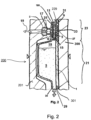
- Fig. 2 shows a blood cassette 200 in cross section.
- the blood cassette 200 is pressed with a treatment device 300.
- the lower area 21 forms the deeper area, i.e. the fluid receiving chamber 1.
- the upper area 23 forms the flatter area, i.e. the fluid supply chamber 3.
- a second fluid 19 is introduced into the fluid supply chamber 3 through a fluid connector 17.
- the fluid supply chamber 3 has, as in Fig. 2 is shown, optionally the rear support structure 11, which is attached to the fluid supply chamber 3 by means of a tight connection 25, for example a welded or adhesive connection.
- the filter membrane 9 is arranged on the rear support structure 11, on which in turn a front support structure 27 is provided.
- the cassette body 201 of the blood cassette 200 is covered on one side with a cover element 229, for example a film.
- the blood cassette 200 is pressed with the treatment device 300 via a rubber mat 301, which can be used to transmit force and/or movements through sensors or actuators of the treatment device 300 to the blood cassette 200 or chambers and/or channels thereof.
- the rubber mat 301 can have a targeted compliance structure 33.
- the fluid receiving chamber 1 can be provided with a fluid connection 35 on its underside.
- Fig. 3 shows an enlarged detail or section of the blood cassette 200 Fig. 2 , more precisely, the filter device 100 in longitudinal section.
- the filter device 100 was tilted by 90 ° so that the fluid connector 17 for the second fluid is shown in the illustration Fig. 3 is directed upwards.
- the tilt is for better display.
- the filter device 100 takes its place Fig. 1 position shown.
- the filter membrane 9 which exemplarily has a membrane layer and a third support layer (not shown) in the form of a fabric, is arranged between the rear support structure 11 and the front support structure 27.
- an optional first ring zone or a first ring region 37 is provided.
- an optional second ring zone or a second ring area 39 is provided.
- the arrows I the Fig. 3 point to the inner or central section of the filter membrane 9. They point inwards from the edge of the filter membrane 9.
- the reference number 9a denotes the back of the filter membrane 9, the reference number 9b the front of the filter membrane 9.
- the filter membrane 9 can carry a carrier fleece on its back 9a and/or its front 9b.
- a carrier fleece can be a fabric; it can have a Teflon layer (alternatively: a polytetrafluoroethylene (PTFE) layer).
- PTFE polytetrafluoroethylene
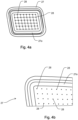
- Fig. 4a shows the front support structure 27 with a first support section 27a.
- the representation of the Fig. 4a corresponds to the view of that side of the front support structure 27, which in turn faces the front side 9b of the filter membrane 9 during use.
- the front support structure 27 has openings 28 leading through it, which will be referred to below Fig. 4b are explained.
- the first support section 27a can, as in Fig. 4a shown as an example, be made of a different material than the remaining sections or other sections of the front support structure 27.
- the first support section 27a can be made of silicone or have silicone and optionally, for example in the form of an O-ring, can be inserted into a groove or a slot in the front support structure 27.
- the front support structure 27 can therefore essentially be made of a comparatively inexpensive and harder material.
- its first support section 27a can be made of a softer material, which is more expensive compared to the harder material, but advantageously different from the harder material when it is placed on the filter membrane 9 and when the front support structure 27 is pressed against the filter membrane 9 cannot lead to any damage.
- the first support section 27a can alternatively - differently than in Fig. 4a shown - according to the invention made of the same material as the remaining sections or other sections of the front support structure 27.
- the entire front Support structure 27 including the first support section 27a may be made of silicone or consist of silicone. This brings manufacturing advantages, but with higher material costs, since silicone is not a cost-effective material.
- the present invention also includes embodiments in which - again different than in Fig. 4a shown - all sections of the front support structure 27 are made of or consist of a material, this material not being silicone. In this way, the front support structure 27 can be manufactured cost-effectively.
- the desired low hardness of the front support structure 27 is achieved when connecting the front support structure 27 to the cassette body 201 during welding and by welding the front support structure 27 in the area of the first support section 27a to the cassette body 201.
- Fig. 4b shows an enlarged section of the front support structure 27 Fig. 4a .
- Openings 28 can be seen, which make the front support structure 27 permeable to the fluid, which can also pass through the filter membrane 9.
- the permeability of the front support structure 27 to the fluid can optionally be caused solely by the openings 28, as in the present example.
- the diameter of (all or many) of the openings 28 is a maximum of 0.7 mm, preferably not more than 0.5 mm. If the openings 28 are designed as elongated holes, the above dimensions apply analogously to the width of the elongated holes.
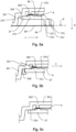
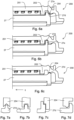
- Fig. 5a shows schematically very simplified and only in sections the blood cassette 200 of an exemplary embodiment according to the invention with the cassette body 201 (is as in the 5b to 5d Shown rotated 180° compared to its depiction in Fig. 3 ), a filter membrane 9, a front support structure 27 and a rubber mat 301.
- the rubber mat 301 is part of an in Fig. 5a blood treatment device 300, not shown, in which the blood cassette 200 is accommodated.
- the filter membrane 9 is welded to the cassette body 201 along a welding section 203.
- the welding section 203 can be closed all around, which is due to the sectional view in Fig. 5a cannot be seen from this figure.
- the welding section 203 can be understood as the first ring area 37, see Fig. 2 .
- the front support structure 27 rests at least partially or in sections on the welding section 203 with a first support section 27a or is in contact with it.
- the first support section 27a projects beyond the welding section 203 in a direction I, i.e. in the direction of the central section of the front support structure 27 or the filter membrane 9. This is in Fig. 5d shown enlarged and explained further.
- the front support structure 27 optionally has knobs or projections 27b, which preferably rise from that side of the front support structure 27 on which the front support structure 27 of the filter membrane 9 rests or with which it faces the filter membrane 9.
- the knobs or projections 27b are arranged on the edge and/or in a central region of the front support structure 27. They have gaps between them so that gas exchange is possible between them.
- the front support structure 27 has one or more knobs or projections 27c, which preferably rise from that side of the front support structure 27 which is opposite that side of the front support structure 27 that faces the filter membrane 9.
- Rubber mat 301 also shown presses on the knobs 27c of the front support structure 27.
- the knobs or projections 27c preferably protrude in a direction D by a predetermined amount.
- the direction D is perpendicular to the main extension plane of the filter membrane 9 and/or perpendicular to the main extension direction of the front support structure 27.
- the dimension can be predetermined such that the end faces 27c 'reach as far as the rubber mat 301.
- the dimension can be predetermined in such a way that the end faces 27c' extend to a level N, at which the cassette body 201 moves in the direction D with an in Fig. 5a foil, not shown, is covered.
- the front support structure 27 optionally has a second support section 27d.
- the second support section 27d rests on a support section 204.
- the support section 204 can be designed as a projection, edge or edge of the cassette body 201.
- the support section 204 and/or the second support section 27d can be closed all around, which is due to the sectional view in Fig. 5c cannot be seen from this figure.
- the first support section 27a lies further inward in relation to the direction I than the second support section 27d.
- Fig. 5b shows schematically very simplified and only in sections the blood cassette 200 of yet another exemplary embodiment according to the invention with the cassette body 201, a filter membrane 9, a front support structure 27 and a flange or a flanged edge 205.
- the flanged edge 205 serves to clamp the front support structure 27 on Cassette body 201 and in particular a compression between the first support section 27a and the welding section 203.
- Fig. 5c shows schematically very simplified and only in sections the blood cassette 200 of yet another exemplary embodiment according to the invention with the cassette body 201, a filter membrane 9, a front support structure 27 and a welded connection between the second support section 27d of the front support structure 27 and the support section 204 of the cassette body 201 .
- Fig. 5d shows in an enlarged view that the first support section 27a contacts or touches the welding section 203 as well as parts of the weld seam 203a, with which the first support section 27a is connected to the welding section 203.
- first support section 27a has a section 203b which protrudes or projects beyond the welding section 203 in - here exactly as an example - a direction I.
- the latter is an optional feature that is already in Fig. 5a to Fig. 5c is shown.
- a free distance between the knobs or projections 27b of the front support structure 27 on the one hand and the filter membrane 9 on the other hand should not exceed 0.5 mm, preferably 0.3 mm. This distance is in Fig. 5d marked with a double arrow. If it is larger than stated above, the filter membrane 9 can be bent too much before it comes to rest on the knobs or projections 27b of the front support structure 27. An undesirably high mechanical load could be the result.
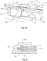
- Fig. 6a to 6c show sections of both the cassette body 201 and the front support structure 27 in different embodiments of the blood cassette 200 according to the invention.
- the second support section 27d is in Fig. 6a designed as a circumferential surface, the plane of which relates to a main plane of extension of the filter membrane 9, not shown, or to the main plane of extension of the front support structure 27 - as in Fig. 5a example shown - runs parallel.
- a - preferably also circumferential - collar or edge 27e rises, the inside and / or outside of which can be at right angles to the circumferential surface of the second support section 27d.
- the edge 27e can be understood as a centering aid when inserting the front support structure 27 into the cassette body 201. It can serve to hold the front support structure 27 while it is welded to the cassette body 201.
- edge is 27e in Fig. 6a
- the second support section 27d and the projecting edge 27e merge into one another; the second support section 27d can be understood as the front section of the projecting edge 27e.
- Fig. 6c are the second support portion 27d and the support portion 204 of the cassette body 201 in Fig. 6c
- the cross section shown is not flat, but curved, triangular or polygonal. This can promote a centering effect.
- the amount of contact between the support section 27d and the support section 204 z. B. area available for welding (ceteris paribus).
- the aforementioned advantages can also be achieved if only the second support portion 27d or the support portion 204 of the cassette body, but not both, are shaped as described above. Examples of this can be found in the following figures.
- Fig. 7a to 7d show various embodiments of the second support section 27d and the support section 204 of the blood cassette 200 according to the invention.
- Fig. 7a and Fig. 7b show versions which correspond to the design Fig. 6c correspond to or are similar to this.
- Fig. 7c shows an embodiment which corresponds to the design Fig. 6a corresponds to or is similar to this.
- Fig. 7d shows an embodiment which corresponds to a combination of the configurations 6b and 6c corresponds.
- the 7b and 7c show designs that are particularly suitable in view of the shrinkage during welding.
- Fig. 8 shows a second filter membrane 10, which is provided instead of or in addition to the support structure 27.
- the filter membrane 9 which in some exemplary embodiments could also be referred to as the first filter membrane for better distinction, has a welding section or a weld 9c, by means of which it is connected to a second filter membrane 10.
- the second filter membrane 10 can be designed like the filter membrane 9 with regard to the features that contribute to the filter effect. This is optional, so not mandatory.
- Fig. 9 shows how Fig. 8 a second filter membrane 10, which is provided instead of or in addition to the support structure 27.
- Both the filter membrane 9 and the second filter membrane 10 are in the embodiment of Fig. 9 divided into either a carrier fleece 9d or 10d, a Teflon layer 9e or 10e, or each have these.
- the filter membrane 9 and the second filter membrane 10 are arranged in such a way that their carrier fleece 9d and 10d face each other.
- the Teflon layers 9e and 10e lie on that side of the carrier fleece 9d and 10d, respectively, which faces away from the other filter membrane 10 and 9, respectively. In other words, the Teflon layers 9e and 10e each point “outwards”.
- Weld seam section 9f connects the carrier fleece 9d to the Teflon layer 9e by welding.
- Weld seam section 10f connects the carrier fleece 10d to the Teflon layer 10e by welding.
- Weld seam section 9f can be provided circumferentially like weld seam section 10f.
- the Teflon layer 9e or 10e can each be made of or have PTFE (polytetrafluoroethylene) or ePTFE (expanded polytetrafluoroethylene).
- Fig. 10 shows a further embodiment of the front support structure 27.
- This front support structure 27 has a profiled structure 29 in its area facing the welding section 203.
- the profiling 29 can be directed or run vertically or approximately vertically into the interior of the support structure 27, so that channels are created between the raised profiles.
- This profiling 29 (combination between raised structures on the one hand and channels on the other) can have the effect that when the structure for attaching the filter membrane to the front support structure 27 melts, the material does not penetrate or only penetrates a little into the central area of the filter membrane, but rather predominantly penetrates into it Channel areas expand.
- FIG. 11 This is schematic in Fig. 11 shown where the material of the raised structures (hatched area of the Fig. 10 ) extends into or into the area of the channels.
- the embodiment of the Fig. 11 the front support structure 27 can therefore be achieved by at least partially melting the raised areas of the front support structure 27 Fig. 10 be producible.
- the profile 29 can be at least partially recognizable in the melted profile 29b.
- the front support structure 27 can differ from the illustration Fig. 11 , also be designed as a parallelogram.
- the profiling 29 can be provided all around in the front support structure 27.
- This front support structure 27 can be formed in one piece and consist of one material. It has been shown that this embodiment can be suitable for supporting the radiation or beam-sterilized filter membrane even without additional softer support elements in such a way that delamination of the filter membrane can be avoided.
- the front support structure 27 may have openings 28. These can be arranged in recesses 30, so that knobs or projections 27b can also be formed flat between the openings 28. In the In the area of the openings 28, the front support structure 27 can also be made thinner than in other areas. The principle is shown in the circled area in a section in an oblique view from the front Fig. 11a shown. As a result, the front support structure 27 can have a profiling 31 on the side facing away from the filter membrane in addition to the flat knobs or projections 27b that face the filter membrane. The thinner design of the support structure 27 in the area of the openings can enable easier gas passage (lower flow resistance); The additional profiling 31 can bring about stabilization in the form of higher bending stiffness.
- All front support structures 27 and blood cassette bodies described above may include or be made of polypropylene.
- Fig. 11a shows an enlarged section of the Fig. 11 .
Landscapes
- Health & Medical Sciences (AREA)
- Heart & Thoracic Surgery (AREA)
- Vascular Medicine (AREA)
- Hematology (AREA)
- Animal Behavior & Ethology (AREA)
- Engineering & Computer Science (AREA)
- Anesthesiology (AREA)
- Biomedical Technology (AREA)
- Veterinary Medicine (AREA)
- Life Sciences & Earth Sciences (AREA)
- Public Health (AREA)
- General Health & Medical Sciences (AREA)
- Urology & Nephrology (AREA)
- Cardiology (AREA)
- Emergency Medicine (AREA)
- External Artificial Organs (AREA)
- Separation Using Semi-Permeable Membranes (AREA)
Applications Claiming Priority (2)
| Application Number | Priority Date | Filing Date | Title |
|---|---|---|---|
| DE102016109196.0A DE102016109196A1 (de) | 2016-05-19 | 2016-05-19 | Medizinische Einrichtung mit optional hydrophober Filtermembran und vorderseitiger Stützstruktur hierfür |
| PCT/EP2017/061734 WO2017198667A1 (de) | 2016-05-19 | 2017-05-16 | Medizinische einrichtung mit optional hydrophober filtermembran und vorderseitiger stützstruktur hierfür |
Publications (2)
| Publication Number | Publication Date |
|---|---|
| EP3458127A1 EP3458127A1 (de) | 2019-03-27 |
| EP3458127B1 true EP3458127B1 (de) | 2023-11-01 |
Family
ID=58739032
Family Applications (1)
| Application Number | Title | Priority Date | Filing Date |
|---|---|---|---|
| EP17724536.2A Active EP3458127B1 (de) | 2016-05-19 | 2017-05-16 | Medizinische einrichtung mit hydrophober filtermembran und vorderseitiger stützstruktur hierfür |
Country Status (11)
| Country | Link |
|---|---|
| US (1) | US20190117868A1 (OSRAM) |
| EP (1) | EP3458127B1 (OSRAM) |
| JP (1) | JP7110115B2 (OSRAM) |
| KR (1) | KR20190010610A (OSRAM) |
| CN (1) | CN109310809B (OSRAM) |
| AU (1) | AU2017266714A1 (OSRAM) |
| CA (1) | CA3021245A1 (OSRAM) |
| DE (1) | DE102016109196A1 (OSRAM) |
| EA (1) | EA201892630A1 (OSRAM) |
| TW (1) | TWI733806B (OSRAM) |
| WO (1) | WO2017198667A1 (OSRAM) |
Families Citing this family (2)
| Publication number | Priority date | Publication date | Assignee | Title |
|---|---|---|---|---|
| ES3049157T3 (en) * | 2018-07-19 | 2025-12-15 | Abiomed Inc | Systems and methods for reducing leaks from a catheter |
| EP4628185A1 (en) * | 2024-04-05 | 2025-10-08 | Sartorius Stedim Biotech GmbH | Filtration unit and method of manufacturing a filtration unit |
Family Cites Families (10)
| Publication number | Priority date | Publication date | Assignee | Title |
|---|---|---|---|---|
| US3631654A (en) * | 1968-10-03 | 1972-01-04 | Pall Corp | Gas purge device |
| US4459139A (en) * | 1981-09-14 | 1984-07-10 | Gelman Sciences Inc. | Disposable filter device and liquid aspirating system incorporating same |
| DE3541521A1 (de) * | 1985-11-23 | 1987-06-04 | Sartorius Gmbh | Filter zum filtrieren menschlichen blutes, insbesondere in einem extrakorporalen kreislauf |
| ITMO20030079A1 (it) * | 2003-03-21 | 2004-09-22 | Gambro Lundia Ab | Dispositivo per proteggere apparati medicali |
| US7069788B2 (en) * | 2003-12-23 | 2006-07-04 | Jms North America Corp. | Double membrane transducer protector |
| JP2008055100A (ja) * | 2006-09-04 | 2008-03-13 | Nipro Corp | 体外循環回路圧力モニター用保護フィルター |
| DE102009018664A1 (de) | 2009-04-23 | 2010-10-28 | Fresenius Medical Care Deutschland Gmbh | Externe Funktionseinrichtung, Blutbehandlungsvorrichtung zum Aufnehmen einer erfindungsgemäßen externen Funktionseinrichtung, sowie Verfahren |
| BRPI1013417B8 (pt) * | 2009-04-23 | 2021-06-22 | Fresenius Medical Care Deutschland Gmbh | meio funcional externo, e, aparelho de tratamento para tratar pelo menos um fluido |
| DE102009024467B4 (de) * | 2009-06-10 | 2015-12-31 | Fresenius Medical Care Deutschland Gmbh | Einrichtung sowie externe Funktionseinrichtung und Behandlungsvorrichtung zum Behandeln von medizinischen Fluiden |
| DE102014011695A1 (de) * | 2014-08-07 | 2016-02-11 | Fresenius Medical Care Deutschland Gmbh | Blutbehandlungsvorrichtung mit einer Funktionseinheit zur Durchführung der Blutbehandlung und Verfahren zur Überprüfung der Funktionsfähigkeit und/oder des Betriebszustandes der Funktionseinheit |
-
2016
- 2016-05-19 DE DE102016109196.0A patent/DE102016109196A1/de not_active Ceased
-
2017
- 2017-05-16 CN CN201780030952.XA patent/CN109310809B/zh active Active
- 2017-05-16 EA EA201892630A patent/EA201892630A1/ru unknown
- 2017-05-16 JP JP2018560630A patent/JP7110115B2/ja active Active
- 2017-05-16 AU AU2017266714A patent/AU2017266714A1/en not_active Abandoned
- 2017-05-16 KR KR1020187036770A patent/KR20190010610A/ko not_active Ceased
- 2017-05-16 CA CA3021245A patent/CA3021245A1/en active Pending
- 2017-05-16 EP EP17724536.2A patent/EP3458127B1/de active Active
- 2017-05-16 US US16/301,605 patent/US20190117868A1/en not_active Abandoned
- 2017-05-16 WO PCT/EP2017/061734 patent/WO2017198667A1/de not_active Ceased
- 2017-05-17 TW TW106116322A patent/TWI733806B/zh active
Also Published As
| Publication number | Publication date |
|---|---|
| KR20190010610A (ko) | 2019-01-30 |
| CA3021245A1 (en) | 2017-11-23 |
| TW201818982A (zh) | 2018-06-01 |
| CN109310809B (zh) | 2021-10-15 |
| BR112018073616A2 (pt) | 2019-02-26 |
| JP2019519283A (ja) | 2019-07-11 |
| US20190117868A1 (en) | 2019-04-25 |
| DE102016109196A1 (de) | 2017-11-23 |
| CN109310809A (zh) | 2019-02-05 |
| AU2017266714A1 (en) | 2018-12-06 |
| WO2017198667A1 (de) | 2017-11-23 |
| TWI733806B (zh) | 2021-07-21 |
| EA201892630A1 (ru) | 2019-05-31 |
| EP3458127A1 (de) | 2019-03-27 |
| JP7110115B2 (ja) | 2022-08-01 |
Similar Documents
| Publication | Publication Date | Title |
|---|---|---|
| DE19828650C2 (de) | Konnektorelement mit integriertem Absperrelement | |
| EP2421579B1 (de) | Ventilvorrichtung, ventileinsatz, externe funktionseinrichtung, behandlungsvorrichtung sowie verfahren | |
| DE69416651T2 (de) | Sammelsystem für körperflüssigkeiten eines patienten | |
| EP2421583B1 (de) | Einrichtung sowie externe funktionseinrichtung und behandlungsvorrichtung zum behandeln von medizinischen fluiden | |
| DE69836021T2 (de) | Filteranordung | |
| DE102009024467B4 (de) | Einrichtung sowie externe Funktionseinrichtung und Behandlungsvorrichtung zum Behandeln von medizinischen Fluiden | |
| DE112019003103T5 (de) | Belüftungseinheit | |
| EP1866008A1 (de) | Ventil, insbesondere für ein brusthaubenset | |
| EP1003600B1 (de) | Filtrationseinheit aus kunststoff und verfahren zu ihrer herstellung | |
| DE102009024469A1 (de) | Ventilvorrichtung, Ventileinsatz, externe Funktionseinrichtung, Behandlungsvorrichtung sowie Verfahren | |
| EP3458127B1 (de) | Medizinische einrichtung mit hydrophober filtermembran und vorderseitiger stützstruktur hierfür | |
| EP3377167B1 (de) | Mehrweghahn mit mehrfachhaltering | |
| DE102014103508B4 (de) | Vorgespanntes Ventil für medizinische Funktionsvorrichtung, und medizinische Funktionsvorrichtung | |
| DE102014103490A1 (de) | Blutbehandlungskassette mit Folienventil und elastischem Abstandhalter sowie Blutbehandlungsvorrichtung | |
| EP3116560B1 (de) | Blutbehandlungskassette mit folienventil und unelastischem abstandhalter sowie blutbehandlungsvorrichtung | |
| EP3116564B1 (de) | Blutbehandlungskassette mit gedelltem folienventil sowie blutbehandlungsvorrichtung | |
| EP3110469B1 (de) | Medizinische flüssigkeitskassette und medizinischer schlauchsatz mit medizinischer flüssigkeitskassette | |
| EP2890441A1 (de) | Konnektor zur herstellung einer fluidverbindung mit einem zweiten konnektor, konnektorsystem und verfahren zur herstellung einer fluidverbindung | |
| DE102023202719A1 (de) | Verschlusskappe für die "inline" sterilisation von dialysatoren | |
| WO2013007837A2 (de) | Peripherer venenkatheter mit schutz gegen blutverspritzen | |
| WO2015136067A1 (de) | Rückschlagventilanordnung, medizinische funktionsvorrichtung und eine blutbehandlungsvorrichtung | |
| DE10114768A1 (de) | Subcutan implantierbare Dialyseporteinrichtung | |
| AT527923B1 (de) | Vorrichtung zum Druckausgleich in einem Gehäuse | |
| DE102021131267A1 (de) | Verschlusskappe für Flüssigkeitsanschlüsse eines Dialysators | |
| EP1721595B2 (de) | Behälter für die Bereitstellung medizinischer Flüssigkeiten |
Legal Events
| Date | Code | Title | Description |
|---|---|---|---|
| STAA | Information on the status of an ep patent application or granted ep patent |
Free format text: STATUS: UNKNOWN |
|
| STAA | Information on the status of an ep patent application or granted ep patent |
Free format text: STATUS: THE INTERNATIONAL PUBLICATION HAS BEEN MADE |
|
| PUAI | Public reference made under article 153(3) epc to a published international application that has entered the european phase |
Free format text: ORIGINAL CODE: 0009012 |
|
| STAA | Information on the status of an ep patent application or granted ep patent |
Free format text: STATUS: REQUEST FOR EXAMINATION WAS MADE |
|
| 17P | Request for examination filed |
Effective date: 20181219 |
|
| AK | Designated contracting states |
Kind code of ref document: A1 Designated state(s): AL AT BE BG CH CY CZ DE DK EE ES FI FR GB GR HR HU IE IS IT LI LT LU LV MC MK MT NL NO PL PT RO RS SE SI SK SM TR |
|
| AX | Request for extension of the european patent |
Extension state: BA ME |
|
| DAV | Request for validation of the european patent (deleted) | ||
| DAX | Request for extension of the european patent (deleted) | ||
| STAA | Information on the status of an ep patent application or granted ep patent |
Free format text: STATUS: EXAMINATION IS IN PROGRESS |
|
| 17Q | First examination report despatched |
Effective date: 20220701 |
|
| GRAP | Despatch of communication of intention to grant a patent |
Free format text: ORIGINAL CODE: EPIDOSNIGR1 |
|
| STAA | Information on the status of an ep patent application or granted ep patent |
Free format text: STATUS: GRANT OF PATENT IS INTENDED |
|
| INTG | Intention to grant announced |
Effective date: 20230109 |
|
| GRAS | Grant fee paid |
Free format text: ORIGINAL CODE: EPIDOSNIGR3 |
|
| GRAJ | Information related to disapproval of communication of intention to grant by the applicant or resumption of examination proceedings by the epo deleted |
Free format text: ORIGINAL CODE: EPIDOSDIGR1 |
|
| GRAL | Information related to payment of fee for publishing/printing deleted |
Free format text: ORIGINAL CODE: EPIDOSDIGR3 |
|
| STAA | Information on the status of an ep patent application or granted ep patent |
Free format text: STATUS: EXAMINATION IS IN PROGRESS |
|
| GRAP | Despatch of communication of intention to grant a patent |
Free format text: ORIGINAL CODE: EPIDOSNIGR1 |
|
| STAA | Information on the status of an ep patent application or granted ep patent |
Free format text: STATUS: GRANT OF PATENT IS INTENDED |
|
| INTC | Intention to grant announced (deleted) | ||
| INTG | Intention to grant announced |
Effective date: 20230526 |
|
| P01 | Opt-out of the competence of the unified patent court (upc) registered |
Effective date: 20230712 |
|
| GRAA | (expected) grant |
Free format text: ORIGINAL CODE: 0009210 |
|
| STAA | Information on the status of an ep patent application or granted ep patent |
Free format text: STATUS: THE PATENT HAS BEEN GRANTED |
|
| AK | Designated contracting states |
Kind code of ref document: B1 Designated state(s): AL AT BE BG CH CY CZ DE DK EE ES FI FR GB GR HR HU IE IS IT LI LT LU LV MC MK MT NL NO PL PT RO RS SE SI SK SM TR |
|
| REG | Reference to a national code |
Ref country code: GB Ref legal event code: FG4D Free format text: NOT ENGLISH |
|
| REG | Reference to a national code |
Ref country code: CH Ref legal event code: EP |
|
| REG | Reference to a national code |
Ref country code: IE Ref legal event code: FG4D Free format text: LANGUAGE OF EP DOCUMENT: GERMAN |
|
| REG | Reference to a national code |
Ref country code: DE Ref legal event code: R096 Ref document number: 502017015553 Country of ref document: DE |
|
| REG | Reference to a national code |
Ref country code: LT Ref legal event code: MG9D |
|
| REG | Reference to a national code |
Ref country code: NL Ref legal event code: MP Effective date: 20231101 |
|
| PG25 | Lapsed in a contracting state [announced via postgrant information from national office to epo] |
Ref country code: GR Free format text: LAPSE BECAUSE OF FAILURE TO SUBMIT A TRANSLATION OF THE DESCRIPTION OR TO PAY THE FEE WITHIN THE PRESCRIBED TIME-LIMIT Effective date: 20240202 |
|
| PG25 | Lapsed in a contracting state [announced via postgrant information from national office to epo] |
Ref country code: IS Free format text: LAPSE BECAUSE OF FAILURE TO SUBMIT A TRANSLATION OF THE DESCRIPTION OR TO PAY THE FEE WITHIN THE PRESCRIBED TIME-LIMIT Effective date: 20240301 |
|
| PG25 | Lapsed in a contracting state [announced via postgrant information from national office to epo] |
Ref country code: LT Free format text: LAPSE BECAUSE OF FAILURE TO SUBMIT A TRANSLATION OF THE DESCRIPTION OR TO PAY THE FEE WITHIN THE PRESCRIBED TIME-LIMIT Effective date: 20231101 |
|
| PG25 | Lapsed in a contracting state [announced via postgrant information from national office to epo] |
Ref country code: NL Free format text: LAPSE BECAUSE OF FAILURE TO SUBMIT A TRANSLATION OF THE DESCRIPTION OR TO PAY THE FEE WITHIN THE PRESCRIBED TIME-LIMIT Effective date: 20231101 |
|
| PG25 | Lapsed in a contracting state [announced via postgrant information from national office to epo] |
Ref country code: ES Free format text: LAPSE BECAUSE OF FAILURE TO SUBMIT A TRANSLATION OF THE DESCRIPTION OR TO PAY THE FEE WITHIN THE PRESCRIBED TIME-LIMIT Effective date: 20231101 |
|
| PG25 | Lapsed in a contracting state [announced via postgrant information from national office to epo] |
Ref country code: NL Free format text: LAPSE BECAUSE OF FAILURE TO SUBMIT A TRANSLATION OF THE DESCRIPTION OR TO PAY THE FEE WITHIN THE PRESCRIBED TIME-LIMIT Effective date: 20231101 Ref country code: LT Free format text: LAPSE BECAUSE OF FAILURE TO SUBMIT A TRANSLATION OF THE DESCRIPTION OR TO PAY THE FEE WITHIN THE PRESCRIBED TIME-LIMIT Effective date: 20231101 Ref country code: IS Free format text: LAPSE BECAUSE OF FAILURE TO SUBMIT A TRANSLATION OF THE DESCRIPTION OR TO PAY THE FEE WITHIN THE PRESCRIBED TIME-LIMIT Effective date: 20240301 Ref country code: GR Free format text: LAPSE BECAUSE OF FAILURE TO SUBMIT A TRANSLATION OF THE DESCRIPTION OR TO PAY THE FEE WITHIN THE PRESCRIBED TIME-LIMIT Effective date: 20240202 Ref country code: ES Free format text: LAPSE BECAUSE OF FAILURE TO SUBMIT A TRANSLATION OF THE DESCRIPTION OR TO PAY THE FEE WITHIN THE PRESCRIBED TIME-LIMIT Effective date: 20231101 Ref country code: BG Free format text: LAPSE BECAUSE OF FAILURE TO SUBMIT A TRANSLATION OF THE DESCRIPTION OR TO PAY THE FEE WITHIN THE PRESCRIBED TIME-LIMIT Effective date: 20240201 Ref country code: PT Free format text: LAPSE BECAUSE OF FAILURE TO SUBMIT A TRANSLATION OF THE DESCRIPTION OR TO PAY THE FEE WITHIN THE PRESCRIBED TIME-LIMIT Effective date: 20240301 |
|
| PG25 | Lapsed in a contracting state [announced via postgrant information from national office to epo] |
Ref country code: SE Free format text: LAPSE BECAUSE OF FAILURE TO SUBMIT A TRANSLATION OF THE DESCRIPTION OR TO PAY THE FEE WITHIN THE PRESCRIBED TIME-LIMIT Effective date: 20231101 Ref country code: RS Free format text: LAPSE BECAUSE OF FAILURE TO SUBMIT A TRANSLATION OF THE DESCRIPTION OR TO PAY THE FEE WITHIN THE PRESCRIBED TIME-LIMIT Effective date: 20231101 Ref country code: PL Free format text: LAPSE BECAUSE OF FAILURE TO SUBMIT A TRANSLATION OF THE DESCRIPTION OR TO PAY THE FEE WITHIN THE PRESCRIBED TIME-LIMIT Effective date: 20231101 Ref country code: NO Free format text: LAPSE BECAUSE OF FAILURE TO SUBMIT A TRANSLATION OF THE DESCRIPTION OR TO PAY THE FEE WITHIN THE PRESCRIBED TIME-LIMIT Effective date: 20240201 Ref country code: LV Free format text: LAPSE BECAUSE OF FAILURE TO SUBMIT A TRANSLATION OF THE DESCRIPTION OR TO PAY THE FEE WITHIN THE PRESCRIBED TIME-LIMIT Effective date: 20231101 Ref country code: HR Free format text: LAPSE BECAUSE OF FAILURE TO SUBMIT A TRANSLATION OF THE DESCRIPTION OR TO PAY THE FEE WITHIN THE PRESCRIBED TIME-LIMIT Effective date: 20231101 |
|
| PG25 | Lapsed in a contracting state [announced via postgrant information from national office to epo] |
Ref country code: DK Free format text: LAPSE BECAUSE OF FAILURE TO SUBMIT A TRANSLATION OF THE DESCRIPTION OR TO PAY THE FEE WITHIN THE PRESCRIBED TIME-LIMIT Effective date: 20231101 |
|
| PG25 | Lapsed in a contracting state [announced via postgrant information from national office to epo] |
Ref country code: CZ Free format text: LAPSE BECAUSE OF FAILURE TO SUBMIT A TRANSLATION OF THE DESCRIPTION OR TO PAY THE FEE WITHIN THE PRESCRIBED TIME-LIMIT Effective date: 20231101 |
|
| PG25 | Lapsed in a contracting state [announced via postgrant information from national office to epo] |
Ref country code: SK Free format text: LAPSE BECAUSE OF FAILURE TO SUBMIT A TRANSLATION OF THE DESCRIPTION OR TO PAY THE FEE WITHIN THE PRESCRIBED TIME-LIMIT Effective date: 20231101 |
|
| PG25 | Lapsed in a contracting state [announced via postgrant information from national office to epo] |
Ref country code: SM Free format text: LAPSE BECAUSE OF FAILURE TO SUBMIT A TRANSLATION OF THE DESCRIPTION OR TO PAY THE FEE WITHIN THE PRESCRIBED TIME-LIMIT Effective date: 20231101 Ref country code: SK Free format text: LAPSE BECAUSE OF FAILURE TO SUBMIT A TRANSLATION OF THE DESCRIPTION OR TO PAY THE FEE WITHIN THE PRESCRIBED TIME-LIMIT Effective date: 20231101 Ref country code: RO Free format text: LAPSE BECAUSE OF FAILURE TO SUBMIT A TRANSLATION OF THE DESCRIPTION OR TO PAY THE FEE WITHIN THE PRESCRIBED TIME-LIMIT Effective date: 20231101 Ref country code: EE Free format text: LAPSE BECAUSE OF FAILURE TO SUBMIT A TRANSLATION OF THE DESCRIPTION OR TO PAY THE FEE WITHIN THE PRESCRIBED TIME-LIMIT Effective date: 20231101 Ref country code: DK Free format text: LAPSE BECAUSE OF FAILURE TO SUBMIT A TRANSLATION OF THE DESCRIPTION OR TO PAY THE FEE WITHIN THE PRESCRIBED TIME-LIMIT Effective date: 20231101 Ref country code: CZ Free format text: LAPSE BECAUSE OF FAILURE TO SUBMIT A TRANSLATION OF THE DESCRIPTION OR TO PAY THE FEE WITHIN THE PRESCRIBED TIME-LIMIT Effective date: 20231101 |
|
| REG | Reference to a national code |
Ref country code: DE Ref legal event code: R097 Ref document number: 502017015553 Country of ref document: DE |
|
| PLBE | No opposition filed within time limit |
Free format text: ORIGINAL CODE: 0009261 |
|
| STAA | Information on the status of an ep patent application or granted ep patent |
Free format text: STATUS: NO OPPOSITION FILED WITHIN TIME LIMIT |
|
| 26N | No opposition filed |
Effective date: 20240802 |
|
| PG25 | Lapsed in a contracting state [announced via postgrant information from national office to epo] |
Ref country code: SI Free format text: LAPSE BECAUSE OF FAILURE TO SUBMIT A TRANSLATION OF THE DESCRIPTION OR TO PAY THE FEE WITHIN THE PRESCRIBED TIME-LIMIT Effective date: 20231101 |
|
| PG25 | Lapsed in a contracting state [announced via postgrant information from national office to epo] |
Ref country code: SI Free format text: LAPSE BECAUSE OF FAILURE TO SUBMIT A TRANSLATION OF THE DESCRIPTION OR TO PAY THE FEE WITHIN THE PRESCRIBED TIME-LIMIT Effective date: 20231101 |
|
| REG | Reference to a national code |
Ref country code: CH Ref legal event code: PL |
|
| PG25 | Lapsed in a contracting state [announced via postgrant information from national office to epo] |
Ref country code: MC Free format text: LAPSE BECAUSE OF FAILURE TO SUBMIT A TRANSLATION OF THE DESCRIPTION OR TO PAY THE FEE WITHIN THE PRESCRIBED TIME-LIMIT Effective date: 20231101 |
|
| PG25 | Lapsed in a contracting state [announced via postgrant information from national office to epo] |
Ref country code: LU Free format text: LAPSE BECAUSE OF NON-PAYMENT OF DUE FEES Effective date: 20240516 |
|
| GBPC | Gb: european patent ceased through non-payment of renewal fee |
Effective date: 20240516 |
|
| PG25 | Lapsed in a contracting state [announced via postgrant information from national office to epo] |
Ref country code: MC Free format text: LAPSE BECAUSE OF FAILURE TO SUBMIT A TRANSLATION OF THE DESCRIPTION OR TO PAY THE FEE WITHIN THE PRESCRIBED TIME-LIMIT Effective date: 20231101 Ref country code: LU Free format text: LAPSE BECAUSE OF NON-PAYMENT OF DUE FEES Effective date: 20240516 Ref country code: CH Free format text: LAPSE BECAUSE OF NON-PAYMENT OF DUE FEES Effective date: 20240531 |
|
| REG | Reference to a national code |
Ref country code: BE Ref legal event code: MM Effective date: 20240531 |
|
| PG25 | Lapsed in a contracting state [announced via postgrant information from national office to epo] |
Ref country code: IE Free format text: LAPSE BECAUSE OF NON-PAYMENT OF DUE FEES Effective date: 20240516 |
|
| PG25 | Lapsed in a contracting state [announced via postgrant information from national office to epo] |
Ref country code: BE Free format text: LAPSE BECAUSE OF NON-PAYMENT OF DUE FEES Effective date: 20240531 |
|
| PG25 | Lapsed in a contracting state [announced via postgrant information from national office to epo] |
Ref country code: GB Free format text: LAPSE BECAUSE OF NON-PAYMENT OF DUE FEES Effective date: 20240516 |
|
| PGFP | Annual fee paid to national office [announced via postgrant information from national office to epo] |
Ref country code: DE Payment date: 20250423 Year of fee payment: 9 |
|
| PGFP | Annual fee paid to national office [announced via postgrant information from national office to epo] |
Ref country code: IT Payment date: 20250423 Year of fee payment: 9 |
|
| REG | Reference to a national code |
Ref country code: AT Ref legal event code: MM01 Ref document number: 1626496 Country of ref document: AT Kind code of ref document: T Effective date: 20240516 |
|
| PGFP | Annual fee paid to national office [announced via postgrant information from national office to epo] |
Ref country code: FR Payment date: 20250423 Year of fee payment: 9 |
|
| PG25 | Lapsed in a contracting state [announced via postgrant information from national office to epo] |
Ref country code: AT Free format text: LAPSE BECAUSE OF NON-PAYMENT OF DUE FEES Effective date: 20240516 |
|
| PG25 | Lapsed in a contracting state [announced via postgrant information from national office to epo] |
Ref country code: CY Free format text: LAPSE BECAUSE OF FAILURE TO SUBMIT A TRANSLATION OF THE DESCRIPTION OR TO PAY THE FEE WITHIN THE PRESCRIBED TIME-LIMIT; INVALID AB INITIO Effective date: 20170516 |
|
| PG25 | Lapsed in a contracting state [announced via postgrant information from national office to epo] |
Ref country code: HU Free format text: LAPSE BECAUSE OF FAILURE TO SUBMIT A TRANSLATION OF THE DESCRIPTION OR TO PAY THE FEE WITHIN THE PRESCRIBED TIME-LIMIT; INVALID AB INITIO Effective date: 20170516 |
|
| PG25 | Lapsed in a contracting state [announced via postgrant information from national office to epo] |
Ref country code: FI Free format text: LAPSE BECAUSE OF FAILURE TO SUBMIT A TRANSLATION OF THE DESCRIPTION OR TO PAY THE FEE WITHIN THE PRESCRIBED TIME-LIMIT Effective date: 20231101 |