EP3458127B1 - Medical device having an hydrophobic filter membrane and having a front-side supporting structure therefor - Google Patents
Medical device having an hydrophobic filter membrane and having a front-side supporting structure therefor Download PDFInfo
- Publication number
- EP3458127B1 EP3458127B1 EP17724536.2A EP17724536A EP3458127B1 EP 3458127 B1 EP3458127 B1 EP 3458127B1 EP 17724536 A EP17724536 A EP 17724536A EP 3458127 B1 EP3458127 B1 EP 3458127B1
- Authority
- EP
- European Patent Office
- Prior art keywords
- support structure
- filter membrane
- front support
- section
- fluid
- Prior art date
- Legal status (The legal status is an assumption and is not a legal conclusion. Google has not performed a legal analysis and makes no representation as to the accuracy of the status listed.)
- Active
Links
- 239000012528 membrane Substances 0.000 title claims description 218
- 230000002209 hydrophobic effect Effects 0.000 title claims description 10
- 239000012530 fluid Substances 0.000 claims description 241
- 239000008280 blood Substances 0.000 claims description 48
- 210000004369 blood Anatomy 0.000 claims description 48
- 239000000463 material Substances 0.000 claims description 46
- 238000004519 manufacturing process Methods 0.000 claims description 10
- 238000002844 melting Methods 0.000 claims description 9
- 230000008018 melting Effects 0.000 claims description 7
- 238000003466 welding Methods 0.000 description 52
- 239000007788 liquid Substances 0.000 description 27
- 239000007789 gas Substances 0.000 description 17
- 239000013598 vector Substances 0.000 description 13
- 239000004809 Teflon Substances 0.000 description 11
- 229920006362 Teflon® Polymers 0.000 description 11
- 230000000694 effects Effects 0.000 description 11
- 229920001296 polysiloxane Polymers 0.000 description 10
- 230000032798 delamination Effects 0.000 description 7
- 238000000034 method Methods 0.000 description 6
- 229920001343 polytetrafluoroethylene Polymers 0.000 description 6
- 239000004810 polytetrafluoroethylene Substances 0.000 description 6
- 230000008901 benefit Effects 0.000 description 5
- 238000001746 injection moulding Methods 0.000 description 5
- HTTJABKRGRZYRN-UHFFFAOYSA-N Heparin Chemical compound OC1C(NC(=O)C)C(O)OC(COS(O)(=O)=O)C1OC1C(OS(O)(=O)=O)C(O)C(OC2C(C(OS(O)(=O)=O)C(OC3C(C(O)C(O)C(O3)C(O)=O)OS(O)(=O)=O)C(CO)O2)NS(O)(=O)=O)C(C(O)=O)O1 HTTJABKRGRZYRN-UHFFFAOYSA-N 0.000 description 4
- 229920000295 expanded polytetrafluoroethylene Polymers 0.000 description 4
- 239000004744 fabric Substances 0.000 description 4
- 229960002897 heparin Drugs 0.000 description 4
- 229920000669 heparin Polymers 0.000 description 4
- 238000002347 injection Methods 0.000 description 4
- 239000007924 injection Substances 0.000 description 4
- 238000009434 installation Methods 0.000 description 4
- -1 polytetrafluoroethylene Polymers 0.000 description 4
- 238000007789 sealing Methods 0.000 description 4
- 230000006835 compression Effects 0.000 description 3
- 238000007906 compression Methods 0.000 description 3
- 238000001914 filtration Methods 0.000 description 3
- 238000003825 pressing Methods 0.000 description 3
- 230000005855 radiation Effects 0.000 description 3
- 230000001954 sterilising effect Effects 0.000 description 3
- 238000004659 sterilization and disinfection Methods 0.000 description 3
- 239000004480 active ingredient Substances 0.000 description 2
- 238000004140 cleaning Methods 0.000 description 2
- 238000004891 communication Methods 0.000 description 2
- 239000011888 foil Substances 0.000 description 2
- 230000035699 permeability Effects 0.000 description 2
- 230000008569 process Effects 0.000 description 2
- 230000007704 transition Effects 0.000 description 2
- 241000894006 Bacteria Species 0.000 description 1
- 239000004743 Polypropylene Substances 0.000 description 1
- FAPWRFPIFSIZLT-UHFFFAOYSA-M Sodium chloride Chemical compound [Na+].[Cl-] FAPWRFPIFSIZLT-UHFFFAOYSA-M 0.000 description 1
- 241000700605 Viruses Species 0.000 description 1
- 230000004308 accommodation Effects 0.000 description 1
- 239000000853 adhesive Substances 0.000 description 1
- 238000004026 adhesive bonding Methods 0.000 description 1
- 230000001070 adhesive effect Effects 0.000 description 1
- 238000005452 bending Methods 0.000 description 1
- 235000013361 beverage Nutrition 0.000 description 1
- 230000015572 biosynthetic process Effects 0.000 description 1
- 230000000903 blocking effect Effects 0.000 description 1
- 239000012159 carrier gas Substances 0.000 description 1
- 238000009833 condensation Methods 0.000 description 1
- 230000005494 condensation Effects 0.000 description 1
- 238000011109 contamination Methods 0.000 description 1
- 230000008878 coupling Effects 0.000 description 1
- 238000010168 coupling process Methods 0.000 description 1
- 238000005859 coupling reaction Methods 0.000 description 1
- 230000007547 defect Effects 0.000 description 1
- 239000000645 desinfectant Substances 0.000 description 1
- 230000001627 detrimental effect Effects 0.000 description 1
- 238000000502 dialysis Methods 0.000 description 1
- 238000007599 discharging Methods 0.000 description 1
- 239000003814 drug Substances 0.000 description 1
- 229940079593 drug Drugs 0.000 description 1
- 239000000839 emulsion Substances 0.000 description 1
- 238000005516 engineering process Methods 0.000 description 1
- 230000007613 environmental effect Effects 0.000 description 1
- 239000003925 fat Substances 0.000 description 1
- 230000005484 gravity Effects 0.000 description 1
- 238000001631 haemodialysis Methods 0.000 description 1
- 238000010438 heat treatment Methods 0.000 description 1
- 230000000322 hemodialysis Effects 0.000 description 1
- 238000002615 hemofiltration Methods 0.000 description 1
- 238000003780 insertion Methods 0.000 description 1
- 230000037431 insertion Effects 0.000 description 1
- 238000007689 inspection Methods 0.000 description 1
- 238000003475 lamination Methods 0.000 description 1
- 239000011344 liquid material Substances 0.000 description 1
- 238000011068 loading method Methods 0.000 description 1
- 230000014759 maintenance of location Effects 0.000 description 1
- 239000000155 melt Substances 0.000 description 1
- 244000005700 microbiome Species 0.000 description 1
- 230000000149 penetrating effect Effects 0.000 description 1
- 230000002572 peristaltic effect Effects 0.000 description 1
- 239000004033 plastic Substances 0.000 description 1
- 229920001155 polypropylene Polymers 0.000 description 1
- 238000002360 preparation method Methods 0.000 description 1
- 230000000284 resting effect Effects 0.000 description 1
- 230000035939 shock Effects 0.000 description 1
- 239000007787 solid Substances 0.000 description 1
- 239000000243 solution Substances 0.000 description 1
- 230000006641 stabilisation Effects 0.000 description 1
- 238000011105 stabilization Methods 0.000 description 1
- 238000003860 storage Methods 0.000 description 1
- 239000000725 suspension Substances 0.000 description 1
- 239000002699 waste material Substances 0.000 description 1
- XLYOFNOQVPJJNP-UHFFFAOYSA-N water Substances O XLYOFNOQVPJJNP-UHFFFAOYSA-N 0.000 description 1
Images


Classifications
-
- A—HUMAN NECESSITIES
- A61—MEDICAL OR VETERINARY SCIENCE; HYGIENE
- A61M—DEVICES FOR INTRODUCING MEDIA INTO, OR ONTO, THE BODY; DEVICES FOR TRANSDUCING BODY MEDIA OR FOR TAKING MEDIA FROM THE BODY; DEVICES FOR PRODUCING OR ENDING SLEEP OR STUPOR
- A61M1/00—Suction or pumping devices for medical purposes; Devices for carrying-off, for treatment of, or for carrying-over, body-liquids; Drainage systems
- A61M1/14—Dialysis systems; Artificial kidneys; Blood oxygenators ; Reciprocating systems for treatment of body fluids, e.g. single needle systems for hemofiltration or pheresis
- A61M1/30—Single needle dialysis ; Reciprocating systems, alternately withdrawing blood from and returning it to the patient, e.g. single-lumen-needle dialysis or single needle systems for hemofiltration or pheresis
- A61M1/301—Details
- A61M1/302—Details having a reservoir for withdrawn untreated blood
-
- A—HUMAN NECESSITIES
- A61—MEDICAL OR VETERINARY SCIENCE; HYGIENE
- A61M—DEVICES FOR INTRODUCING MEDIA INTO, OR ONTO, THE BODY; DEVICES FOR TRANSDUCING BODY MEDIA OR FOR TAKING MEDIA FROM THE BODY; DEVICES FOR PRODUCING OR ENDING SLEEP OR STUPOR
- A61M1/00—Suction or pumping devices for medical purposes; Devices for carrying-off, for treatment of, or for carrying-over, body-liquids; Drainage systems
- A61M1/14—Dialysis systems; Artificial kidneys; Blood oxygenators ; Reciprocating systems for treatment of body fluids, e.g. single needle systems for hemofiltration or pheresis
- A61M1/30—Single needle dialysis ; Reciprocating systems, alternately withdrawing blood from and returning it to the patient, e.g. single-lumen-needle dialysis or single needle systems for hemofiltration or pheresis
- A61M1/301—Details
- A61M1/304—Treatment chamber used as reservoir, e.g. centrifuge bowl or filter with movable membrane
-
- A—HUMAN NECESSITIES
- A61—MEDICAL OR VETERINARY SCIENCE; HYGIENE
- A61M—DEVICES FOR INTRODUCING MEDIA INTO, OR ONTO, THE BODY; DEVICES FOR TRANSDUCING BODY MEDIA OR FOR TAKING MEDIA FROM THE BODY; DEVICES FOR PRODUCING OR ENDING SLEEP OR STUPOR
- A61M1/00—Suction or pumping devices for medical purposes; Devices for carrying-off, for treatment of, or for carrying-over, body-liquids; Drainage systems
- A61M1/14—Dialysis systems; Artificial kidneys; Blood oxygenators ; Reciprocating systems for treatment of body fluids, e.g. single needle systems for hemofiltration or pheresis
- A61M1/15—Dialysis systems; Artificial kidneys; Blood oxygenators ; Reciprocating systems for treatment of body fluids, e.g. single needle systems for hemofiltration or pheresis with a cassette forming partially or totally the flow circuit for the treating fluid, e.g. the dialysate fluid circuit or the treating gas circuit
- A61M1/156—Constructional details of the cassette, e.g. specific details on material or shape
- A61M1/1563—Details of incorporated filters
-
- A—HUMAN NECESSITIES
- A61—MEDICAL OR VETERINARY SCIENCE; HYGIENE
- A61M—DEVICES FOR INTRODUCING MEDIA INTO, OR ONTO, THE BODY; DEVICES FOR TRANSDUCING BODY MEDIA OR FOR TAKING MEDIA FROM THE BODY; DEVICES FOR PRODUCING OR ENDING SLEEP OR STUPOR
- A61M1/00—Suction or pumping devices for medical purposes; Devices for carrying-off, for treatment of, or for carrying-over, body-liquids; Drainage systems
- A61M1/14—Dialysis systems; Artificial kidneys; Blood oxygenators ; Reciprocating systems for treatment of body fluids, e.g. single needle systems for hemofiltration or pheresis
- A61M1/30—Single needle dialysis ; Reciprocating systems, alternately withdrawing blood from and returning it to the patient, e.g. single-lumen-needle dialysis or single needle systems for hemofiltration or pheresis
- A61M1/301—Details
- A61M1/303—Details having a reservoir for treated blood to be returned
-
- A—HUMAN NECESSITIES
- A61—MEDICAL OR VETERINARY SCIENCE; HYGIENE
- A61M—DEVICES FOR INTRODUCING MEDIA INTO, OR ONTO, THE BODY; DEVICES FOR TRANSDUCING BODY MEDIA OR FOR TAKING MEDIA FROM THE BODY; DEVICES FOR PRODUCING OR ENDING SLEEP OR STUPOR
- A61M1/00—Suction or pumping devices for medical purposes; Devices for carrying-off, for treatment of, or for carrying-over, body-liquids; Drainage systems
- A61M1/36—Other treatment of blood in a by-pass of the natural circulatory system, e.g. temperature adaptation, irradiation ; Extra-corporeal blood circuits
- A61M1/3621—Extra-corporeal blood circuits
- A61M1/3622—Extra-corporeal blood circuits with a cassette forming partially or totally the blood circuit
- A61M1/36226—Constructional details of cassettes, e.g. specific details on material or shape
- A61M1/362261—Constructional details of cassettes, e.g. specific details on material or shape at least one cassette surface or portion thereof being flexible, e.g. the cassette having a rigid base portion with preformed channels and being covered with a foil
-
- A—HUMAN NECESSITIES
- A61—MEDICAL OR VETERINARY SCIENCE; HYGIENE
- A61M—DEVICES FOR INTRODUCING MEDIA INTO, OR ONTO, THE BODY; DEVICES FOR TRANSDUCING BODY MEDIA OR FOR TAKING MEDIA FROM THE BODY; DEVICES FOR PRODUCING OR ENDING SLEEP OR STUPOR
- A61M1/00—Suction or pumping devices for medical purposes; Devices for carrying-off, for treatment of, or for carrying-over, body-liquids; Drainage systems
- A61M1/36—Other treatment of blood in a by-pass of the natural circulatory system, e.g. temperature adaptation, irradiation ; Extra-corporeal blood circuits
- A61M1/3621—Extra-corporeal blood circuits
- A61M1/3622—Extra-corporeal blood circuits with a cassette forming partially or totally the blood circuit
- A61M1/36226—Constructional details of cassettes, e.g. specific details on material or shape
- A61M1/362263—Details of incorporated filters
- A61M1/362264—Details of incorporated filters the filter being a blood filter
-
- A—HUMAN NECESSITIES
- A61—MEDICAL OR VETERINARY SCIENCE; HYGIENE
- A61M—DEVICES FOR INTRODUCING MEDIA INTO, OR ONTO, THE BODY; DEVICES FOR TRANSDUCING BODY MEDIA OR FOR TAKING MEDIA FROM THE BODY; DEVICES FOR PRODUCING OR ENDING SLEEP OR STUPOR
- A61M1/00—Suction or pumping devices for medical purposes; Devices for carrying-off, for treatment of, or for carrying-over, body-liquids; Drainage systems
- A61M1/36—Other treatment of blood in a by-pass of the natural circulatory system, e.g. temperature adaptation, irradiation ; Extra-corporeal blood circuits
- A61M1/3621—Extra-corporeal blood circuits
- A61M1/3643—Priming, rinsing before or after use
- A61M1/3644—Mode of operation
- A61M1/3646—Expelling the residual body fluid after use, e.g. back to the body
-
- A—HUMAN NECESSITIES
- A61—MEDICAL OR VETERINARY SCIENCE; HYGIENE
- A61M—DEVICES FOR INTRODUCING MEDIA INTO, OR ONTO, THE BODY; DEVICES FOR TRANSDUCING BODY MEDIA OR FOR TAKING MEDIA FROM THE BODY; DEVICES FOR PRODUCING OR ENDING SLEEP OR STUPOR
- A61M1/00—Suction or pumping devices for medical purposes; Devices for carrying-off, for treatment of, or for carrying-over, body-liquids; Drainage systems
- A61M1/36—Other treatment of blood in a by-pass of the natural circulatory system, e.g. temperature adaptation, irradiation ; Extra-corporeal blood circuits
- A61M1/3621—Extra-corporeal blood circuits
- A61M1/3643—Priming, rinsing before or after use
- A61M1/3644—Mode of operation
- A61M1/3652—Mode of operation using gas, e.g. air
-
- A—HUMAN NECESSITIES
- A61—MEDICAL OR VETERINARY SCIENCE; HYGIENE
- A61M—DEVICES FOR INTRODUCING MEDIA INTO, OR ONTO, THE BODY; DEVICES FOR TRANSDUCING BODY MEDIA OR FOR TAKING MEDIA FROM THE BODY; DEVICES FOR PRODUCING OR ENDING SLEEP OR STUPOR
- A61M2205/00—General characteristics of the apparatus
- A61M2205/12—General characteristics of the apparatus with interchangeable cassettes forming partially or totally the fluid circuit
- A61M2205/125—General characteristics of the apparatus with interchangeable cassettes forming partially or totally the fluid circuit with incorporated filters
- A61M2205/126—General characteristics of the apparatus with interchangeable cassettes forming partially or totally the fluid circuit with incorporated filters with incorporated membrane filters
-
- A—HUMAN NECESSITIES
- A61—MEDICAL OR VETERINARY SCIENCE; HYGIENE
- A61M—DEVICES FOR INTRODUCING MEDIA INTO, OR ONTO, THE BODY; DEVICES FOR TRANSDUCING BODY MEDIA OR FOR TAKING MEDIA FROM THE BODY; DEVICES FOR PRODUCING OR ENDING SLEEP OR STUPOR
- A61M2205/00—General characteristics of the apparatus
- A61M2205/75—General characteristics of the apparatus with filters
- A61M2205/7536—General characteristics of the apparatus with filters allowing gas passage, but preventing liquid passage, e.g. liquophobic, hydrophobic, water-repellent membranes
-
- A—HUMAN NECESSITIES
- A61—MEDICAL OR VETERINARY SCIENCE; HYGIENE
- A61M—DEVICES FOR INTRODUCING MEDIA INTO, OR ONTO, THE BODY; DEVICES FOR TRANSDUCING BODY MEDIA OR FOR TAKING MEDIA FROM THE BODY; DEVICES FOR PRODUCING OR ENDING SLEEP OR STUPOR
- A61M2207/00—Methods of manufacture, assembly or production
Landscapes
- Health & Medical Sciences (AREA)
- Heart & Thoracic Surgery (AREA)
- Vascular Medicine (AREA)
- Hematology (AREA)
- Animal Behavior & Ethology (AREA)
- Engineering & Computer Science (AREA)
- Anesthesiology (AREA)
- Biomedical Technology (AREA)
- Veterinary Medicine (AREA)
- Life Sciences & Earth Sciences (AREA)
- Public Health (AREA)
- General Health & Medical Sciences (AREA)
- Urology & Nephrology (AREA)
- Cardiology (AREA)
- Emergency Medicine (AREA)
- External Artificial Organs (AREA)
- Separation Using Semi-Permeable Membranes (AREA)
Description
Die vorliegende Erfindung betrifft eine medizinische Einrichtung gemäß Anspruch 1.The present invention relates to a medical device according to claim 1.
Ein Herstellverfahren für eine medizinische Einrichtung wird weiter beschrieben.A manufacturing process for a medical facility is further described.
Bekannte Blutbehandlungsvorrichtungen werden zur Blutbehandlung mit einer medizinischen Einrichtung verbunden, beispielsweise mit einer Blutkassette, in welcher Blut behandelt oder vorübergehend gespeichert wird. Derartige Blutkassetten sind aus der
Aufgabe der vorliegenden Erfindung ist, eine weitere medizinische Einrichtung anzugeben.The object of the present invention is to provide a further medical facility.
Diese Aufgabe wird durch eine medizinische Einrichtung mit den Merkmalen des Anspruchs 1 gelöst.This task is achieved by a medical facility with the features of claim 1.
Ferner wird ein nicht beanspruchtes Herstellverfahren für eine solche Einrichtung vorgeschlagen.Furthermore, an unclaimed manufacturing process for such a device is proposed.
Erfindungsgemäß wird somit eine medizinische Einrichtung mit einem Einrichtungskörper (oder Einrichtungskorpus) vorgeschlagen.According to the invention, a medical device with a device body (or device body) is therefore proposed.
Der Einrichtungskörper, oder ein anderer Abschnitt der medizinischen Einrichtung, weist wenigstens ein Fluidsystem für ein erstes medizinisches Fluids, insbesondere Blut, auf. Das Fluidsystem kann teilweise oder vollständig der Einrichtungskörper sein. Der Einrichtungskörper kann an der Bildung des Fluidsystems beteiligt sein. Das Fluidsystem kann jeweils einen oder mehrere Kanäle, Leitungen und/oder Fluidkammern aufweisen.The device body, or another section of the medical device, has at least one fluid system for a first medical fluid, in particular blood. The fluid system can be partially or completely the device body. The device body can be involved in the formation of the fluid system. The fluid system may each have one or more channels, lines and/or fluid chambers.
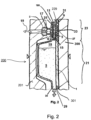
Der Einrichtungskörper, oder ein anderer Abschnitt der medizinischen Einrichtung, weist ferner wenigstens eine - vorzugsweise hydrophobe - Filtereinrichtung auf. Die Filtereinrichtung ist derart ausgestaltet und angeordnet, dass dem Fluidsystem durch die Filteroberfläche hindurch ein zweites, gasförmiges Fluid, insbesondere Luft, zuführbar ist.The device body, or another section of the medical device, also has at least one - preferably hydrophobic - filter device. The filter device is designed and arranged in such a way that a second, gaseous fluid, in particular air, can be supplied to the fluid system through the filter surface.
Die Filtereinrichtung weist wenigstens eine Filtermembran auf. Die Filtermembran weist eine Rückseite und eine Vorderseite auf.The filter device has at least one filter membrane. The filter membrane has a back and a front.
Die Rückseite kann jene Seite der Filtermembran sein, welche einer optionalen Fluidaufnahmekammer des Fluidsystems oder einem optionalen Abdeckelement (z. B. einer Folie) der medizinischen Einrichtung abgewandt ist.The back side can be that side of the filter membrane which faces away from an optional fluid receiving chamber of the fluid system or an optional cover element (e.g. a film) of the medical device.
Die Rückseite kann jene Seite der Filtermembran sein, auf welcher bei bestimmungsgemäßem Gebrauch der erfindungsgemäßen Einrichtung keine Flüssigkeit vorliegt.The back can be that side of the filter membrane on which there is no liquid when the device according to the invention is used as intended.
Die Vorderseite kann jene Seite der Filtermembran sein, welche einer optionalen Fluidaufnahmekammer des Fluidsystems oder einem optionalen Abdeckelement (z. B. einer Folie) der medizinischen Einrichtung zugewandt ist.The front side can be that side of the filter membrane which faces an optional fluid receiving chamber of the fluid system or an optional cover element (e.g. a film) of the medical device.
Die Vorderseite kann jene Seite der Filtermembran sein, auf welcher bei bestimmungsgemäßem Gebrauch der erfindungsgemäßen Einrichtung eine Flüssigkeit vorliegt.The front side can be that side of the filter membrane on which a liquid is present when the device according to the invention is used as intended.
Die Filtermembran ist mittels ihrer Rückseite - direkt oder indirekt - oder an oder auf ihrer Rückseite mit dem Einrichtungskörper, beispielsweise mit der optionalen Fluidaufnahmekammer, oder einer Wandung hiervon, verschweißt. Hierdurch ist ein Schweißabschnitt, ein Schweißnahtabschnitt oder eine Schweißverbindung ausgestaltet. Der verschweißte Abschnitt der Filtermembran, insbesondere seine Rückseite, kann als Schweißabschnitt, Schweißnahtabschnitt oder als Schweißverbindung verstanden werden.The filter membrane is welded by means of its back - directly or indirectly - or on or on its back to the device body, for example to the optional fluid receiving chamber, or a wall thereof. This creates a weld section, a weld seam section or a weld connection. The welded section of the filter membrane, especially its back, can be used as Welding section, weld seam section or as a welded connection can be understood.
Die Filtereinrichtung weist eine auf der Vorderseite der Filtermembran oder vor der Filtermembran angeordnete Stützstruktur auf oder wird durch diese begrenzt. Da diese Stützstruktur an der Vorderseite der Filtermembran liegt, vor der Vorderseite liegt oder der Vorderseite zugewandt ist, wird sie hierin auch als vordere (alternativ: vorderseitige) Stützstruktur bezeichnet.The filter device has a support structure arranged on the front of the filter membrane or in front of the filter membrane or is limited by it. Since this support structure lies on the front of the filter membrane, lies in front of the front or faces the front, it is also referred to herein as a front (alternatively: front-side) support structure.
Die vordere Stützstruktur ist vorzugsweise zum Stützen der Filtermembran angeordnet oder kann in einigen Gebrauchssituationen diesem Zweck dienen. Ein Stützen kann ein Begrenzen, Halten, Kontaktieren, Berühren oder dergleichen sein. Ein Stützen kann ein Verhindern einer unzulässigen Ausbeulung der Filtermembran bei Aufbringen von Druck auf die Rückseite der Filtermembran sein.The front support structure is preferably arranged to support the filter membrane or may serve this purpose in some use situations. Support can be limiting, holding, contacting, touching or the like. Support can be to prevent undue bulging of the filter membrane when pressure is applied to the back of the filter membrane.
Eine Ausbeulung kann dadurch entstehen, dass ein Druckabfall über die Filtermembran generiert wird oder auftritt. Dies kann durch ein Absenken des Drucks auf der Vorderseite oder durch ein Erhöhen des Drucks auf der Rückseite der Filtermembran erreicht werden. Das Filterelement kann ein Verbindungselement aufweisen zum Verbinden mit einer Leitung einer Blutbehandlungsvorrichtung, in der mittels einer Pumpe ein Überdruck generierbar ist. Bei dieser Pumpe kann es sich um einen Kompressor oder ein Überdruckreservoir handeln. Mittels dieser Pumpe kann ein Flüssigkeitsniveau in einer mit der Filtermembran in Kontakt stehenden Flüssigkeitskammer absenkbar sein.A bulge can occur because a pressure drop is generated or occurs across the filter membrane. This can be achieved by lowering the pressure on the front or increasing the pressure on the back of the filter membrane. The filter element can have a connecting element for connecting to a line of a blood treatment device in which an overpressure can be generated by means of a pump. This pump can be a compressor or a pressure reservoir. By means of this pump, a liquid level in a liquid chamber in contact with the filter membrane can be lowered.
Die Verwendung von "vorderer" heißt nicht, dass es eine "hintere" Stützstruktur geben muss, obgleich dies in einigen, beispielhaften Ausführungsformen der Fall sein kann.The use of "front" does not mean that there must be a "rear" support structure, although in some example embodiments there may be.
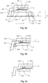
Die vordere Stützstruktur weist einen ersten Auflageabschnitt auf und steht mit diesem mit dem Schweißabschnitt in Kontakt.The front support structure has a first support section and is in contact with the welding section.
Ein nicht beanspruchtes Verfahren zum Herstellen einer medizinischen Einrichtung, insbesondere einer erfindungsgemäßen medizinischen Einrichtung, wird ferner vorgeschlagen.An unclaimed method for producing a medical device, in particular a medical device according to the invention, is also proposed.
Das Verfahren dient dem Herstellen einer medizinischen Einrichtung, insbesondere einer erfindungsgemäßen Einrichtung. Es umfasst das Bereitstellen eines Einrichtungskörpers einer medizinischen Einrichtung mit einem Fluidsystem für ein erstes Fluid.The method is used to produce a medical device, in particular a device according to the invention. It includes providing a device body of a medical device with a fluid system for a first fluid.
Es umfasst ferner ein Bereitstellen einer Filtereinrichtung mit einer Filteroberfläche, durch welche ein zweites, gasförmiges Fluid, insbesondere Luft, durchführbar ist. Die Filtereinrichtung weist wenigstens eine Filtermembran auf; wobei die Filtermembran eine Rückseite und eine Vorderseite hat und wobei die Filtermembran mit ihrer Rückseite mit einem Abschnitt des Einrichtungskörpers entlang eines Schweißabschnitts verschweißt ist.It further includes providing a filter device with a filter surface through which a second, gaseous fluid, in particular air, can be passed. The filter device has at least one filter membrane; wherein the filter membrane has a back and a front and wherein the filter membrane has its back welded to a portion of the device body along a welding section.
Weiter umfasst das Verfahren das Bereitstellen einer Stützstruktur oder vorderen Stützstruktur.The method further includes providing a support structure or front support structure.
Die vordere Stützstruktur ist auf der Vorderseite der Filtermembran am Einrichtungskörper angeordnet. Dies geschieht derart, dass die vordere Stützstruktur mittels eines ersten Auflageabschnitts der vorderen Stützstruktur mit dem Schweißabschnitt in Kontakt steht.The front support structure is arranged on the front of the filter membrane on the device body. This happens in such a way that the front support structure is in contact with the welding section by means of a first support section of the front support structure.
Schließlich wird die vordere Stützstruktur mit der Vorderseite der Filtermembran verschweißt. Letzteres kann unter Erweichen von Material der vorderen Stützstruktur erfolgen.Finally, the front support structure is welded to the front of the filter membrane. The latter can be done by softening material of the front support structure.
Bei allen Ausführungen hierin ist der Gebrauch des Ausdrucks "kann sein" bzw. "kann haben" usw. synonym zu "ist vorzugsweise" bzw. "hat vorzugsweise" usw. zu verstehen und soll eine erfindungsgemäße Ausführungsform erläutern.In all statements herein, the use of the expression "may be" or "may have" etc. is to be understood as synonymous with "is preferably" or "preferably has" etc. and is intended to explain an embodiment of the invention.
Erfindungsgemäße Ausführungsformen können eines oder mehrere der vorstehend oder im Folgenden genannten Merkmale aufweisen. Dabei können die hierin genannten Merkmale in beliebiger Kombinationen Gegenstand von erfindungsgemäßen Ausführungsformen sein, sofern der Fachmann eine konkrete Kombination nicht als technisch unmöglich erkennt. Erfindungsgemäße Ausführungsformen sind ferner Gegenstand der Unteransprüche.Embodiments according to the invention can have one or more of the features mentioned above or below. The features mentioned here can be the subject of embodiments according to the invention in any combination, provided that the person skilled in the art does not recognize a specific combination as technically impossible. Embodiments according to the invention are also the subject of the subclaims.
Wann immer hierin Zahlenworte genannt werden, so versteht der Fachmann diese als Angabe einer zahlenmäßig unteren Grenze. Sofern dies zu keinem für den Fachmann erkennbaren Widerspruch führt, liest der Fachmann daher beispielsweise bei der Angabe "ein" oder "einem" stets "wenigstens ein" oder "wenigstens einem" mit. Dieses Verständnis ist ebenso von der vorliegenden Erfindung mit umfasst wie die Auslegung, dass ein Zahlenwort wie beispielsweise "ein" alternativ als "genau ein" gemeint sein kann, wo immer dies für den Fachmann erkennbar technisch möglich ist. Beides ist von der vorliegenden Erfindung umfasst und gilt für alle hierin verwendeten Zahlenworte.Whenever numerical words are mentioned herein, the person skilled in the art understands these as indicating a numerically lower limit. Unless this leads to a contradiction that is recognizable to the person skilled in the art, the person skilled in the art will therefore always read “at least one” or “at least one” when “a” or “one” is stated. This understanding is also included in the present invention, as is the interpretation that a numerical word such as "a" can alternatively be meant as "exactly a", wherever this is technically possible for a person skilled in the art. Both are encompassed by the present invention and apply to all number words used herein.
Die Angaben "oben" und "unten" sind hierin bei Zweifel des Fachmanns als absolute oder relative Raumangaben zu verstehen, welche sich auf die Ausrichtung des betreffenden Bauteils während seines üblichen Gebrauchs beziehen.In the event of doubt by a person skilled in the art, the information "above" and "below" is to be understood as absolute or relative spatial information, which relates to the orientation of the component in question during its normal use.
Die Angaben "vordere" und "hintere" usw. sind hierin bei Zweifel des Fachmanns als absolute oder relative Raumangaben zu verstehen, welche sich auf die medizinische Einrichtung beziehen. Weist die medizinische Einrichtung ein Abdeckelement auf, so liegt dieses auf der vorderen Seite oder Vorderseite der medizinischen Einrichtung.If the expert has any doubts, the information “front” and “rear” etc. should be understood as absolute or relative spatial information which relates to the medical facility. If the medical facility has a cover element, this is located on the front side or front of the medical facility.
Unter einem "Kontakt" kann hierin stets beispielsweise ein Berühren, ein Kraftschluss, ein Formschluss, ein Stoffschluss (z. B. durch Verschweißen miteinander) oder ein gegenseitiges Verpressen zwischen den in Frage bzw. "in Kontakt" stehenden Komponenten verstanden werden. Ein Kontakt kann ein direkter Kontakt (z. B. ein direktes Berühren) oder ein indirekter Kontakt (z. B. über eine Zwischenschicht hinweg; die Zwischenschicht kann eine Membran sein) sein.A “contact” can always be understood here as meaning, for example, touching, a frictional connection, a positive connection, a material connection (e.g. by welding to one another) or a mutual pressing between the components in question or “in contact”. A contact can be a direct contact (e.g. a direct contact) or indirect contact (e.g. across an intermediate layer; the intermediate layer can be a membrane).
In einigen erfindungsgemäßen, beispielhaften Ausführungsformen ist die erfindungsgemäße medizinische Einrichtung ein Schlauchsystem, ein Schlauchset, eine Blutkassette oder jeweils ein Teil hiervon.In some exemplary embodiments according to the invention, the medical device according to the invention is a hose system, a hose set, a blood cassette or a part thereof.
Der Begriff "Fluidaufnahmekammer", wie er hierin verwendet wird, bezeichnet beispielsweise eine Kammer, oder einen Teil hiervon, oder einen Behälter, oder einen Teil hiervon, welche/r ein Inneres oder einen Innenraum aufweist, der zum vollständigen oder teilweise Befüllen mit Fluiden und Aufnehmen derselben geeignet und bestimmungsgemäß vorgesehen ist.The term "fluid receiving chamber" as used herein means, for example, a chamber, or a part thereof, or a container, or a part thereof, which has an interior or an interior space suitable for being completely or partially filled with fluids and Recording the same is suitable and intended as intended.
In einigen erfindungsgemäßen, beispielhaften Ausführungsformen weist die Fluidaufnahmekammer genau zwei Fluidzu- oder -ausgänge auf. Eine der beiden führt durch die Filtermembran hindurch und dient dem Zuführen und/oder Abführen von Gas, vorzugsweise nur von Gas, nicht auch von Flüssigkeit. Der andere ist der Fluidanschluss zum Zuführen und/oder Abführen von Flüssigkeit, etwa dem ersten Fluid.In some exemplary embodiments according to the invention, the fluid receiving chamber has exactly two fluid inlets or outlets. One of the two leads through the filter membrane and serves to supply and/or remove gas, preferably only gas, not also liquid. The other is the fluid connection for supplying and/or discharging liquid, such as the first fluid.
Ein "erstes Fluid" im Sinne der vorliegenden Erfindung schließt jede medizinische Flüssigkeit und/oder jedes medizinische Gas sowie beliebige Kombinationen ein, welche(s) zum Einbringen in eine erfindungsgemäße Aufnahmeeinrichtung angedacht bzw. vorgesehen ist. Vorzugsweise handelt es sich bei dem ersten Fluid um Blut.A “first fluid” in the sense of the present invention includes any medical liquid and/or any medical gas as well as any combinations which are intended or intended for introduction into a receiving device according to the invention. Preferably the first fluid is blood.
Der Begriff "erstes Fluid" wird deshalb gleichbedeutend mit dem Begriff "medizinisches Fluid" verwendet.The term “first fluid” is therefore used synonymously with the term “medical fluid”.
Ein "zweites Fluid" ist ein gasförmiges Fluid, oder weist ein Gas auf, vorzugsweise Luft.A "second fluid" is a gaseous fluid, or includes a gas, preferably air.
Der Begriff "Filtereinrichtung" oder "hydrophobe Filtereinrichtung", wie er hierin gleichbedeutend verwendet wird, bezeichnet beispielsweise eine Einrichtung, welche dazu ausgelegt und vorgesehen ist, eine Filterwirkung auf Fluide, welche durch die Fluidaufnahmekammer hindurchzuführen sind, auszuüben. Alternativ bezeichnet eine Filtereinrichtung i. S. d. Erfindung eine Membran ohne Filterwirkung.The term “filter device” or “hydrophobic filter device”, as used interchangeably herein, denotes, for example, a device which is designed and intended to exert a filtering effect on fluids which are to be passed through the fluid receiving chamber. Alternatively, a filter device i. S.d. Invention of a membrane without a filter effect.
Die Filterwirkung kann z. B. eine Reinigung der der Fluidaufnahmekammer zuzuführenden Fluide, insbesondere zum Beispiel das Zurückhalten von Feststoffen, Kleinstlebewesen, wie Viren oder Bakterien, und dergleichen umfassen.The filter effect can e.g. B. cleaning of the fluids to be supplied to the fluid receiving chamber, in particular, for example, the retention of solids, microorganisms such as viruses or bacteria, and the like.
Die Filterwirkung kann auch umfassen, dass der Filter durchlässig für Gas, nicht jedoch für eine Flüssigkeit, insbesondere Wasser oder Blut, ist. Dadurch kann es möglich sein, ein Eindringen der Flüssigkeit in einen Bereich jenseits der Filtermembran zu verhindern. Ist beispielsweise die durch die Filtermembran begrenzte Fluidkammer durch eine Öffnung mit der Maschine verbunden, kann verhindert werden, dass die Maschine kontaminiert wird, wenn die Flüssigkeit in Richtung zur Filtermembran vordringt.The filter effect can also include that the filter is permeable to gas, but not to a liquid, in particular water or blood. This may make it possible to prevent the liquid from penetrating into an area beyond the filter membrane. For example, if the fluid chamber delimited by the filter membrane is connected to the machine through an opening, the machine can be prevented from becoming contaminated when the liquid advances towards the filter membrane.
In einigen, beispielhaften erfindungsgemäßen Ausführungsformen weist die vordere Stützstruktur einen zweiten Auflageabschnitt auf. Dabei ist die vordere Stützstruktur angeordnet, um mittels des zweiten Auflageabschnitts mit einem Stützabschnitt des Einrichtungskörpers in Kontakt zu stehen, und/oder steht mit diesem in Kontakt.In some exemplary embodiments of the invention, the front support structure has a second support portion. The front support structure is arranged to be in contact with a support section of the device body by means of the second support section and/or is in contact with it.
In einigen, beispielhaften erfindungsgemäßen Ausführungsformen ist der zweite Auflageabschnitt mit dem Stützabschnitt des Einrichtungskörpers verschweißt.In some exemplary embodiments according to the invention, the second support section is welded to the support section of the device body.
In einigen, beispielhaften erfindungsgemäßen Ausführungsformen ist der zweite Auflageabschnitt mit dem Stützabschnitt des Einrichtungskörpers verklebt.In some exemplary embodiments according to the invention, the second support section is glued to the support section of the device body.
In einigen, beispielhaften erfindungsgemäßen Ausführungsformen sind der Schweißabschnitt und/oder der erste Auflageabschnitt umlaufende oder geschlossene Abschnitte oder Ringbereiche.In some exemplary embodiments according to the invention, the welding section and/or the first support section are circumferential or closed sections or ring areas.
In einigen, beispielhaften erfindungsgemäßen Ausführungsformen ist der zweite Auflageabschnitt mit dem Stützabschnitt des Einrichtungskörpers verklemmt.In some exemplary embodiments according to the invention, the second support section is clamped to the support section of the device body.
Hierzu kann eine Klemmeinrichtung vorgesehen sein.A clamping device can be provided for this purpose.
Die Klemmeinrichtung kann als Bördelung oder Bördelkante ausgestaltet sein oder eine solche aufweisen.The clamping device can be designed as a flange or flanged edge or have one.
Die Klemmeinrichtung, Bördelung oder Bördelkante können umlaufende oder geschlossene Abschnitte sein.The clamping device, flanging or flanging edge can be circumferential or closed sections.
In einigen, beispielhaften erfindungsgemäßen Ausführungsformen ist der erste Auflageabschnitt der vorderen Stützstruktur aus einem weicheren Material als andere Abschnitte oder als alle anderen Abschnitte der vorderen Stützstruktur gefertigt oder weist ein weicheres Material als jene Abschnitte auf.In some exemplary embodiments of the invention, the first support portion of the front support structure is made of or has a softer material than other portions or all other portions of the front support structure.
Als (relativ zu anderen Abschnitten gesehen) "weicheres" Material kommt Silikon in Frage. Dies ist vergleichsweise teuer, weshalb es sich anbietet, beispielsweise nur den ersten Auflageabschnitt hieraus zu fertigen. Für andere Abschnitte der vorderen Stützstruktur, für welche die besonderen Eigenschaften von Silikon nicht erforderlich sind oder gar nachteilig sein können (etwa die hohe Nachgiebigkeit von aus Silikon gefertigten Komponenten, welche der Idee des Stützens zuwiderläuft), kann ein - verglichen mit Silikon oder verglichen mit dem Material des ersten Auflageabschnitts - steiferes oder härteres Material ausgewählt sein.Silicone can be considered as a “softer” material (relative to other sections). This is comparatively expensive, which is why it is advisable, for example, to only make the first support section from this. For other sections of the front support structure for which the special properties of silicone are not required or may even be disadvantageous (such as the high flexibility of components made of silicone, which runs counter to the idea of support), a - compared to silicone or compared to the material of the first support section - stiffer or harder material must be selected.
In einigen, beispielhaften erfindungsgemäßen Ausführungsformen ist der erste Auflageabschnitt der vorderen Stützstruktur dauerhaft aus einem weicheren Material, in anderen ist das betreffende Material nur vorübergehend, etwa bei der Fertigung (durch Schweißen, z. B.) weicher und verhärtet sich optional anschließend wieder.In some exemplary embodiments according to the invention, the first support section of the front support structure is permanently made of a softer material, in others the material in question is only temporarily softer, for example during production (by welding, for example) and optionally hardens again afterwards.
In einigen, beispielhaften erfindungsgemäßen Ausführungsformen ist die vordere Stützstruktur aus genau einem Material gefertigt oder besteht aus genau einem Material. In einigen, beispielhaften erfindungsgemäßen Ausführungsformen steht der erste Auflageabschnitt der vorderen Stützstruktur mit dem Schweißnahtabschnitt des Einrichtungskörpers in - vorzugsweise direktem - Kontakt. Vorzugsweise steht der Schweißnahtabschnitt ausschließlich mit dem ersten Auflageabschnitt in Verbindung.In some exemplary embodiments of the invention, the front support structure is made of or consists of exactly one material. In some exemplary embodiments according to the invention, the first support section of the front support structure is in - preferably direct - contact with the weld seam section of the device body. Preferably, the weld seam section is exclusively connected to the first support section.
Erfindungsgemäß überragt der erste Auflageabschnitt der vorderen Stützstruktur den Schweißabschnitt des Einrichtungskörpers in wenigstens einer Richtung oder auf wenigstens einer Seite des Schweißabschnitts oder steht über den Schweißabschnitt über. Die Richtung kann parallel zur Haupterstreckungsrichtung der vorderen Stützstruktur oder der Filtermembran verlaufen. Ein Überragen oder Überstehen erfolgt erfindungsgemäß in Richtung auf einen inneren oder zentralen Abschnitt der Filtermembran oder der vorderen Stützstruktur und/oder in Richtung eines Bereichs der Filtermembran, der im Gebrauch mit Druck oder am stärksten mit Druck beaufschlagt wird.According to the invention, the first support section of the front support structure projects beyond the welding section of the device body in at least one direction or on at least one side of the welding section or protrudes beyond the welding section. The direction can be parallel to the main extension direction of the front support structure or the filter membrane. According to the invention, protruding or protruding takes place in the direction of an inner or central section of the filter membrane or the front support structure and/or in the direction of an area of the filter membrane which is pressurized or is subjected to the greatest pressure during use.
In einigen, beispielhaften erfindungsgemäßen Ausführungsformen ist der erste Auflageabschnitt der vorderen Stützstruktur lösbar von weiteren Abschnitten der vorderen Stützstruktur mit den weiteren Abschnitten verbunden. Die Verbindung kann durch ein Einstecken erzielt sein.In some exemplary embodiments according to the invention, the first support section of the front support structure is detachably connected to the further sections from further sections of the front support structure. The connection can be achieved by plugging in.
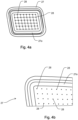
In einigen, beispielhaften erfindungsgemäßen Ausführungsformen ist die vordere Stützstruktur ein flächiges oder planes Gitter oder weist ein solches auf.In some exemplary embodiments according to the invention, the front support structure is or has a flat or planar grid.
In einigen, beispielhaften erfindungsgemäßen Ausführungsformen weist die vordere Stützstruktur Öffnungen auf.In some exemplary embodiments of the invention, the front support structure has openings.
In einigen, beispielhaften erfindungsgemäßen Ausführungsformen unterscheidet sich der erste Auflageabschnitt der vorderen Stützstruktur farblich von weiteren Abschnitten der vorderen Stützstruktur.In some exemplary embodiments according to the invention, the first support section of the front support structure differs in color from other sections of the front support structure.
So kann der erste Auflageabschnitt z. B. blau oder einen anderen vergleichsweise dunklen Ton haben, während die vordere Stützstruktur grau oder weiß oder transparent ist. Auf diese Weise kann der die medizinische Einrichtung fertigende Mitarbeiter oder der die medizinische Einrichtung später zur Behandlung des Patienten einsetzende Arzt oder Mitarbeiter auf Station auf einen Blick überprüfen, ob die oftmals separat vom Einrichtungskörper gefertigte vordere Stützstruktur tatsächlich in den Einrichtungskörper eingelegt wurde. Dies erleichtert die Endkontrolle nach Beendigung der Herstellung. Zudem kann es zur Sicherheit des Patienten beitragen, indem fehlerhafte medizinische Einrichtungen selbst am Patientenbett noch frühzeitig erkannt werden können.So the first support section can z. B. have blue or another comparatively dark tone, while the front support structure is gray or white or transparent. In this way, the employee who manufactures the medical device or the doctor or employee on the ward who later uses the medical device to treat the patient can check at a glance whether the front support structure, which is often manufactured separately from the device body, has actually been inserted into the device body. This makes the final inspection easier after production has been completed. It can also contribute to patient safety by allowing faulty medical equipment to be detected early, even at the patient's bedside.
In einigen, beispielhaften erfindungsgemäßen Ausführungsformen weist die vordere Stützstruktur Öffnungen auf. Der Durchmesser oder die Breite der Öffnungen beträgt maximal 0,7 mm, vorzugsweise maximal 0,5 mm. Diese Maße haben sich als bevorzugt erwiesen, um einen Kompromiss zwischen Durchlassfläche einerseits und Abstützung der Filtermembran andererseits zu gewährleisten. Sind die Öffnungen größer als hierin angegeben, so kann die Filtermembran bei Druck zu sehr in die Öffnungen hineingedrückt werden. Dies kann eine Durchlässigkeit vermindern. Ferner kann die Filtermembran unerwünscht stark mechanisch belastet werden. Bei den vorgeschlagenen Öffnungsgrößen kann die Filtermembran vorteilhaft mit mindestens 3 bar beaufschlagt werden.In some exemplary embodiments of the invention, the front support structure has openings. The diameter or width of the openings is a maximum of 0.7 mm, preferably a maximum of 0.5 mm. These dimensions have proven to be preferred in order to ensure a compromise between the passage area on the one hand and the support of the filter membrane on the other. If the openings are larger than specified here, the filter membrane can be pushed too far into the openings under pressure. This can reduce permeability. Furthermore, the filter membrane can be subjected to undesirable mechanical stress. With the proposed opening sizes, the filter membrane can advantageously be pressurized with at least 3 bar.
In einigen, beispielhaften erfindungsgemäßen Ausführungsformen weist die vordere Stützstruktur eine zweite Filtermembran auf oder besteht hieraus.In some exemplary embodiments of the invention, the front support structure includes or consists of a second filter membrane.
In einigen, beispielhaften erfindungsgemäßen Ausführungsformen ist der erste Auflageabschnitt der vorderen Stützstruktur ein während der Herstellung der Einrichtung durch Aufschmelzen oder vorübergehendem Verflüssigen von Material entstandener Abschnitt oder weist einen solchen auf. Dieser aufgeschmolzene Abschnitt kann z. B. als ein flächig verlaufender Materialabschnitt erkennbar sein, der sich von den verglichen hiermit klar definierten, nicht aufgeschmolzenen und/oder optisch erkennbar auf andere Weise gefertigten oder behandelten, übrigen Strukturen der vorderen Stützstruktur abgrenzt.In some exemplary embodiments of the invention, the first support portion of the front support structure is or includes a portion formed during manufacture of the device by melting or temporarily liquefying material. This melted section can z. B. as a flat material section can be seen, which is separated from the remaining structures of the front support structure that are clearly defined, not melted and / or visually recognizable in a different way.
In einigen, beispielhaften erfindungsgemäßen Ausführungsformen weist die vordere Stützstruktur in ihrem dem Schweißnahtabschnitt zugewandten Bereich eine profilierte oder laminierte Struktur auf. Die Profilierung oder Laminierung kann dabei parallel oder schräg zur Haupterstreckungsebene der Stützstruktur verlaufende Kanäle ergeben. Diese Kombination zwischen erhabenen Strukturen und Kanälen, also die Profilierung, kann bewirken, dass bei einem Aufschmelzen der Struktur zum Befestigen der Filtermembran an der vorderen Stützstruktur aufgeschmolzenes Material nicht oder nur in geringer Menge in den zentralen Bereich der Filtermembran eindringt, sondern sich überwiegen in die Kanalbereiche ausdehnt. Dies kann die Öffnungen der vorderen Stützstruktur und die Filtermembran vor einem Verkleben durch aufgeschmolzenes Material schützen.In some exemplary embodiments according to the invention, the front support structure has a profiled or laminated structure in its region facing the weld seam section. The profiling or lamination can result in channels running parallel or obliquely to the main extension plane of the support structure. This combination between raised structures and channels, i.e. the profiling, can have the effect that when the structure for attaching the filter membrane to the front support structure is melted, melted material does not penetrate into the central area of the filter membrane or only penetrates in a small amount, but predominates in the Channel areas expand. This can protect the openings of the front support structure and the filter membrane from sticking by melted material.
Die Filtereinrichtung ist in einigen, beispielhaften erfindungsgemäßen Ausführungsformen derart angeordnet, dass ein Normalenvektor auf die Filteroberfläche der optional hydrophoben Filtereinrichtung bei bestimmungsgemäßem Gebrauch der medizinischen Einrichtung und mehr oder weniger mit erstem Fluid befüllter Fluidaufnahmekammer nicht parallel zu einem Normalenvektor auf die Ebene des Fluidpegels bzw. des Fluidspiegels des in der Fluidaufnahmekammer vorhandenen ersten Fluids verläuft. Die beiden Normalenvektoren liegen, anders ausgedrückt, in diesen erfindungsgemäßen Ausführungsformen nicht in einer Ebene.In some exemplary embodiments according to the invention, the filter device is arranged in such a way that a normal vector on the filter surface of the optionally hydrophobic filter device is not parallel to a normal vector on the plane of the fluid level or the fluid receiving chamber when the medical device is used as intended and the fluid receiving chamber is more or less filled with the first fluid Fluid level of the first fluid present in the fluid receiving chamber. In other words, the two normal vectors do not lie in one plane in these embodiments according to the invention.
Der Begriff "Normalenvektor", wie er hierin in Bezug auf die Filteroberfläche verwendet wird, bezeichnet in einigen, beispielhaften erfindungsgemäßen Ausführungsformen einen Normalenvektor zu einem beliebigen Oberflächenabschnitt der Filtereinrichtung. Der Normalenvektor auf die Filteroberfläche kann eine Senkrechte zu einer Haupterstreckungsebene der Filtereinrichtung, besonders bevorzugt eine Senkrechte zu einer Oberfläche eines Hauptabschnitts der Filtereinrichtung, ganz besonders bevorzugt eine Senkrechte zu einem mittleren Abschnitt der Filtereinrichtung oder eine Senkrechte zu einem filternden Abschnitt der Filtereinrichtung oder der nicht-filternden Membran sein. Ein solcher Normalenvektor auf die Filteroberfläche kann ein senkrechtes Lot oder eine Senkrechte auf einen der zuvor genannten Abschnitte darstellen.The term "normal vector" as used herein with respect to the filter surface means, in some exemplary embodiments of the invention, a normal vector to any surface portion of the filter device. The normal vector to the filter surface can be a perpendicular to a main extension plane of the filter device, particularly preferably a perpendicular to a surface of a main section of the filter device, very particularly preferably be a perpendicular to a central section of the filter device or a perpendicular to a filtering section of the filter device or the non-filtering membrane. Such a normal vector to the filter surface can represent a perpendicular perpendicular or a perpendicular to one of the previously mentioned sections.
Der Begriff "Normalenvektor auf die Ebene des Fluidspiegels", wie er hierin verwendet wird, bezeichnet - in Anlehnung an die vorstehend angegebene Definition für den Normalenvektor auf die Filteroberfläche - einen Normalenvektor zu einem beliebigen Abschnitt bzw. Bereich der Ebene des Fluidspiegels.The term "normal vector to the plane of the fluid level" as used herein refers - based on the definition given above for the normal vector to the filter surface - to a normal vector to any portion or region of the plane of the fluid level.
Der Begriff "Fluidspiegel" bezieht sich erfindungsgemäß auf einen Fluidspiegel oder - pegel (diese beiden Begriffe werden nachfolgend synonym zueinander verwendet) eines zum Gebrauch der medizinischen Einrichtung in die Fluidaufnahmekammer aufgenommenen ersten Fluids.According to the invention, the term “fluid level” refers to a fluid level or level (these two terms are used synonymously with one another below) of a first fluid that is received into the fluid receiving chamber for use of the medical device.
Bei Schwapp- und/oder Strömungsbewegungen, beispielsweise Rotations- und/oder Wellenbewegungen der sich in der Fluidaufnahmekammer befindenden Fluide kann es schwierig sein, einen Fluidspiegel oder eine Senkrechte hierauf zu bestimmen. Daher wird unter einem Fluidspiegel erfindungsgemäß bevorzugt ein unter Berücksichtigung aller Schwapp- und/oder Strömungsbewegungen der sich in der Fluidaufnahmekammer befindenden Fluide gemittelter Durchschnittspegel oder -spiegel verstanden.In the case of sloshing and/or flow movements, for example rotational and/or wave movements, of the fluids located in the fluid receiving chamber, it can be difficult to determine a fluid level or a perpendicular to it. Therefore, according to the invention, a fluid level is preferably understood to mean an average level or mirror taking into account all sloshing and/or flow movements of the fluids located in the fluid receiving chamber.
Der Fluidspiegel kann vorzugsweise in einem Strömungs-Ruhezustand des Fluids bestimmt werden. Es ist unerheblich, ob ein solcher Ruhezustand im Gebrauch der medizinischen Einrichtung erreicht wird. Es genügt für die vorliegenden Zwecke, einen solchen anzunehmen oder zu approximieren.The fluid level can preferably be determined in a flow rest state of the fluid. It is irrelevant whether such a resting state is achieved during use of the medical facility. For present purposes it is sufficient to assume or approximate one.
In einigen, beispielhaften erfindungsgemäßen Ausführungsformen steht der Normalenvektor auf die Filteroberfläche im Wesentlichen senkrecht zum Normalenvektor auf die Ebene des Fluidspiegels.In some exemplary embodiments according to the invention, the normal vector to the filter surface is essentially perpendicular to the normal vector to the plane of the fluid mirror.
Der Begriff "im Wesentlichen senkrecht", wie er hierin verwendet wird, umfasst Abweichungen von der Rechtwinkeligkeit, die z.B. daher rühren, dass die erfindungsgemäße medizinische Einrichtung, welche die Einrichtung aufweist, im Gebrauch eine geringe Neigung, z.B. bis zu +/- 15°, aufweist, während bei einer solchen Neigung der Filtereinrichtung der Fluid- oder Flüssigkeitspegel in der medizinischen Einrichtung trotzdem horizontal bleibt.The term "substantially perpendicular" as used herein includes deviations from perpendicularity, which arise, for example, from the fact that the medical device according to the invention, which has the device, has a slight inclination in use, for example up to +/- 15 ° , while with such an inclination of the filter device the fluid or liquid level in the medical device still remains horizontal.
In einigen, beispielhaften erfindungsgemäßen Ausführungsformen hat ein Normalenvektor auf die Filteroberfläche keinen Schnittpunkt mit einem Fluidspiegel - wie oben definiert - des während des Gebrauchs in der Fluidaufnahmekammer vorhandenen ersten Fluids.In some exemplary embodiments of the invention, a normal vector to the filter surface does not intersect with a fluid level - as defined above - of the first fluid present in the fluid receiving chamber during use.
In einigen, beispielhaften erfindungsgemäßen Ausführungsformen weist die medizinische Einrichtung wenigstens eine Fluidzuführungskammer zum Zuführen des zweiten Fluids auf.In some exemplary embodiments according to the invention, the medical device has at least one fluid supply chamber for supplying the second fluid.
Der Begriff "Fluidzuführungskammer", wie er hierin verwendet wird, bezeichnet eine Kammer oder einen Behälter, welche/r ein Inneres oder einen Innenraum aufweist, der zum Aufnehmen eines zweiten Fluids und Zuführen desselben in die Fluidaufnahmekammer geeignet und bestimmt ist.The term "fluid delivery chamber" as used herein refers to a chamber or container having an interior suitable and intended for receiving a second fluid and supplying it to the fluid receiving chamber.
Die Fluidzuführungskammer kann in Form einer Spritzgusskammer hergestellt sein. Die Fluidzuführungskammer kann eine Einmal-Fluidzuführungskammer sein.The fluid supply chamber can be made in the form of an injection molding chamber. The fluid delivery chamber may be a disposable fluid delivery chamber.
Die Fluidzuführungskammer kann in wenigstens einem Abschnitt derselben mit der Fluidaufnahmekammer verbunden sein.The fluid supply chamber may be connected to the fluid receiving chamber in at least a portion thereof.
Sie kann stoffschlüssig mit der Fluidaufnahmekammer verbunden oder in diese integriert sein.It can be cohesively connected to the fluid receiving chamber or integrated into it.
Die Fluidzuführungskammer kann beispielsweise während der Herstellung der Fluidaufnahmekammer ausgestaltet worden sein.The fluid supply chamber can, for example, have been designed during the manufacture of the fluid receiving chamber.
Die Fluidzuführungskammer kann durch wenigstens eine Abgrenzung oder eine Teilwand von der Fluidaufnahmekammer abgetrennt sein.The fluid supply chamber can be separated from the fluid receiving chamber by at least one boundary or a partial wall.
In einigen, beispielhaften erfindungsgemäßen Ausführungsformen ist die Filtereinrichtung in einem Inneren der Fluidzuführungskammer angeordnet.In some exemplary embodiments according to the invention, the filter device is arranged in an interior of the fluid supply chamber.
Die Fluidzuführungskammer und die Fluidaufnahmekammer stehen bevorzugt lediglich über die Filtereinrichtung miteinander in Fluidkommunikation.The fluid supply chamber and the fluid receiving chamber are preferably in fluid communication with one another only via the filter device.
Bevorzugt wird dabei das zweite Fluid im Gebrauch der medizinischen Einrichtung aus der Fluidzuführungskammer durch die Filtereinrichtung in die Fluidaufnahmekammer eingebracht bzw. dieser zugeführt.During use of the medical device, the second fluid is preferably introduced from the fluid supply chamber through the filter device into the fluid receiving chamber or fed thereto.
Ganz besonders bevorzugt ist die Filtereinrichtung derart ausgestaltet und vorgesehen, dass ein sich in der Fluidaufnahmekammer befindendes erstes Fluid und insbesondere ein flüssiges Fluid nicht durch die Filtereinrichtung in die Fluidzuführungskammer gelangen kann.Very particularly preferably, the filter device is designed and provided in such a way that a first fluid and in particular a liquid fluid located in the fluid receiving chamber cannot pass through the filter device into the fluid supply chamber.
In einigen, beispielhaften erfindungsgemäßen Ausführungsformen kann das zweite Fluid über einen Fluidkonnektor, welcher mit der Fluidzuführungskammer verbindbar oder verbunden ist, in die Fluidzuführungskammer eingebracht, eingeströmt, eingeleitet oder dergleichen werden.In some exemplary embodiments according to the invention, the second fluid can be introduced, flowed in, introduced or the like into the fluid supply chamber via a fluid connector which can be connected or is connected to the fluid supply chamber.
Der Fluidkonnektor kann ein hülsenförmiges Gebilde sein. Er kann aus einem Stück mit einer Wandung bzw. Seitenwand der Fluidzuführungskammer hergestellt sein. Er kann auf bzw. an einer Außenseite der Wandung oder Seitenwand der Fluidzuführungskammer vorgesehen sein. Er kann innerhalb eines Bereichs der in der Fluidzuführungskammer angeordneten Filtereinrichtung vorgesehen sein. Er kann direkt mit der Filtereinrichtung verbunden bzw. an diese angeschlossen sein.The fluid connector can be a sleeve-shaped structure. It can be made in one piece with a wall or side wall of the fluid supply chamber. It can be provided on or on an outside of the wall or side wall of the fluid supply chamber. It can be within a range of the fluid supply chamber arranged filter device can be provided. It can be connected directly to the filter device or connected to it.
Der Fluidkonnektor kann über eine oder mehrere Verbindungsbohrungen mit einer Innenseite der Wandung oder Seitenwand der Fluidzuführungskammer verbunden sein.The fluid connector can be connected to an inside of the wall or side wall of the fluid supply chamber via one or more connecting bores.
Der Fluidkonnektor kann angeordnet sein, um unmittelbar ein Fluid von einem äußeren der medizinischen Einrichtung in ein Inneres einzuführen.The fluid connector can be arranged to directly introduce a fluid from an exterior of the medical device into an interior.
In einigen, beispielhaften erfindungsgemäßen Ausführungsformen kann die Fluidaufnahmekammer beispielsweise in Form einer Spritzgusskammer hergestellt sein.In some exemplary embodiments according to the invention, the fluid receiving chamber can be manufactured, for example, in the form of an injection molding chamber.
Die Fluidaufnahmekammer kann eine Einmal-Fluidaufnahmekammer sein.The fluid receiving chamber may be a disposable fluid receiving chamber.
Die Fluidaufnahmekammer kann eine Fluidverbindung zu einem Äußeren der Kammer aufweisen. Sie kann zwei oder mehr Fluidverbindungen zum Äußeren der Kammer aufweisen.The fluid receiving chamber may have fluid communication with an exterior of the chamber. It may have two or more fluid connections to the exterior of the chamber.
Die Fluidaufnahmekammer kann eine oder genau eine Fluidverbindung allein zu einem Inneren der Kammer aufweisen. Sie kann zwei oder mehr Fluidverbindungen zum Inneren der Kammer aufweisen.The fluid receiving chamber can have one or exactly one fluid connection solely to an interior of the chamber. It may have two or more fluid connections to the interior of the chamber.
Die Fluidaufnahmekammer ist mittels der Filtermembran bevorzugt vom Fluidkonnektor der Fluidzuführungskammer und/oder von einem Äußeren der medizinischen Einrichtung entkoppelt, was eine Flüssigkeitsverbindung betrifft.The fluid receiving chamber is preferably decoupled from the fluid connector of the fluid supply chamber and/or from an exterior of the medical device by means of the filter membrane, as far as a fluid connection is concerned.
Die Filtermembran kann eine beliebige geeignete Form aufweisen. Sie kann beispielsweise rund, eckig, insbesondere rechteckig, elliptisch und dergleichen ausgestaltet sein.The filter membrane can have any suitable shape. For example, it can be designed round, square, in particular rectangular, elliptical and the like.
Die Filtermembran kann aus einem Filtermembranband ausgeschnitten und/oder gegebenenfalls auf eine bestimmte Form zugeschnitten werden oder sein.The filter membrane can be cut out of a filter membrane band and/or optionally tailored to a specific shape.
Die Filtermembran kann eine Einmal-Filtermembran sein.The filter membrane can be a disposable filter membrane.
Die Filtermembran kann eine hydrophobe Membran sein. Die Filtermembran kann an wenigstens einer Seite hydrophob sein.The filter membrane can be a hydrophobic membrane. The filter membrane can be hydrophobic on at least one side.
Die Filtermembran kann aus zwei Schichten bestehen, nämlich erstens der eigentlichen Membran, die zumeist aus einem schwer schweißbaren und schwer klebbaren Werkstoff besteht, wie z.B. PTFE (Polytetrafluorethylen) oder ePTFE (expanded Polytetrafluoroethylen), und zweitens einer Schicht, die eine Drainage- und/oder Stützfunktion hat und zumeist aus Gewebe und/oder Vlies besteht oder dieses aufweist, das schweißbar und/oder klebbar ist. Die Filtermembran kann alternativ neben den zuvor genannten Schichten weitere Schichten oder Bestandteile aufweisen.The filter membrane can consist of two layers, namely firstly the actual membrane, which usually consists of a material that is difficult to weld and stick, such as PTFE (polytetrafluoroethylene) or ePTFE (expanded polytetrafluoroethylene), and secondly a layer that provides a drainage and/or or has a supporting function and usually consists of or has fabric and/or fleece that can be welded and/or glued. The filter membrane can alternatively have further layers or components in addition to the previously mentioned layers.
Die Filtermembran kann eine Sterilmembran sein.The filter membrane can be a sterile membrane.
Die Filtermembran kann aus einem nicht oder nur schwierig verklebbaren und/oder einem nicht oder nur schwierig verschweißbaren Werkstoff bestehen oder einen solchen aufweisen.The filter membrane can consist of or have a material that is difficult or impossible to bond and/or a material that is impossible or difficult to weld.
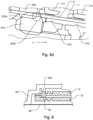
Die Filtermembran kann während der Verwendung der medizinischen Einrichtung, wie beispielsweise der Dauer einer Behandlung, wechselnden Drücken aus Richtung der Fluidaufnahmekammer (ausströmendes Gas, anstehende Flüssigkeit) und/oder aus Richtung einer Behandlungsvorrichtung (einströmendes Gas, anstehende Störfallflüssigkeit und/oder aus Kondensation entstehende unerwünschte Flüssigkeit) ausgesetzt sein. Zum Schutz der Filtermembran im flächigen Nutzbereich und/oder an den Stellen ihrer Abdichtung (in der Regel Verschweißung) z.B. an Wandungen der Fluidzuführungskammer vor Verformung durch diese Druckdifferenzen, welche zu einem Strukturschaden oder einem Riss in der Membran führen könnte, kann es von Vorteil sein, die Filtermembran mechanisch abzustützen.During use of the medical device, such as the duration of a treatment, the filter membrane can be subject to changing pressures from the direction of the fluid receiving chamber (outflowing gas, pending liquid) and/or from the direction of a treatment device (inflowing gas, pending incident liquid and/or undesirable ones arising from condensation). liquid). To protect the filter membrane in the flat usable area and/or at the points of its sealing (usually welding), for example on walls of the fluid supply chamber, from deformation caused by these pressure differences, which are too If this could result in structural damage or a crack in the membrane, it may be advantageous to mechanically support the filter membrane.
Zum Erzielen einer solchen mechanischen Abstützung kann eine Stützstruktur eingesetzt werden. Diese ist derart ausgestaltet, dass die Stützflächen die Filtermembran nicht unzulässig gegen den gewünschten Fluiddurchtritt durch die Filtermembran, z.B. einen Nutzgasdurchtritt, abdichten.A support structure can be used to achieve such mechanical support. This is designed in such a way that the support surfaces do not impermissibly seal the filter membrane against the desired fluid passage through the filter membrane, for example a useful gas passage.
Die Filtereinrichtung kann symmetrisch oder asymmetrisch aufgebaut sein.The filter device can be constructed symmetrically or asymmetrically.
In einigen, beispielhaften erfindungsgemäßen Ausführungsformen weist die Filtereinrichtung auf bzw. an beiden Seiten eine Stützstruktur auf, also sowohl an der Vorderseite als auch an der Rückseite der Filtermembran.In some exemplary embodiments according to the invention, the filter device has a support structure on or on both sides, i.e. both on the front and on the back of the filter membrane.
Zusätzlich zu der vorderen Stützstruktur kann auf der Rückseite der Filtermembran eine hierin als "hintere" Stützstruktur bezeichnete Stützstruktur vorliegen. Die beiden Stützstrukturen können getrennt voneinander vorliegen.In addition to the front support structure, a support structure referred to herein as a "rear" support structure may be present on the back of the filter membrane. The two support structures can be present separately from one another.
Eine dritte Stützstruktur kann auf der Membranschicht selbst angeordnet sein. Sie kann vorzugsweise als Vlies, Gewebe oder dergleichen ausgestaltet sein.A third support structure can be arranged on the membrane layer itself. It can preferably be designed as a fleece, fabric or the like.
Die hintere Stützstruktur ist vorzugsweise im Inneren des Gehäuses des Fluidkonnektors vorgesehen. Sie kann eine Drainagestruktur aufweisen. Die hintere Stützstruktur kann eine Drainagewirkung haben.The rear support structure is preferably provided inside the housing of the fluid connector. It can have a drainage structure. The posterior support structure can have a drainage effect.
Die hintere Stützstruktur kann kraft- und/oder form- und/oder stoffschlüssig mit der Fluidzuführungskammer verbunden sein. Bevorzugt ist die hintere Stützstruktur in einem äußeren umlaufenden Bereich kraft- und/oder form- und/oder stoffschlüssig mit der Fluidzuführungskammer oder einem anderen Abschnitt des Einrichtungskörpers verbunden.The rear support structure can be connected to the fluid supply chamber in a force-fitting and/or positive and/or material-locking manner. Preferably, the rear support structure is connected to the fluid supply chamber or another section of the device body in a force-fitting and/or form-fitting and/or material-locking manner in an outer circumferential area.
Da die Filtermembran in der Regel aus einem nicht oder schlecht verklebbaren und/oder einem nicht oder schlecht verschweißbaren Werkstoff besteht, kann die dem Inneren der Fluidzuführungskammer zugewandte Stützstruktur in wenigstens einem äußeren Bereich, bevorzugt einem äußeren, umlaufenden Bereich, derselben mit der Fluidzuführungskammer verbunden sein.Since the filter membrane generally consists of a material that cannot be bonded or is poorly bonded and/or a material that is difficult or impossible to weld, the support structure facing the interior of the fluid supply chamber can be connected to the fluid supply chamber in at least one outer region, preferably an outer, circumferential region of the same .
Bevorzugter Weise ist die hintere Stützstruktur stoffschlüssig mit der Fluidzufiihrungskammer oder einem anderen Abschnitt des Einrichtungskörpers verbunden, beispielsweise verschweißt, z.B. mittels Thermoschweißen, Spiegelschweißen, Ultraschallschweißen oder Laserschweißen. Die hintere Stützstruktur kann thermisch mit der Fluidzuführungskammer bzw. einem Verbindungsbereich derselben verschweißt sein.Preferably, the rear support structure is cohesively connected to the fluid supply chamber or another section of the device body, for example welded, for example by means of thermal welding, mirror welding, ultrasonic welding or laser welding. The rear support structure may be thermally welded to the fluid supply chamber or a connecting region thereof.
Zu diesem Zweck ist die hintere Stützstruktur - bevorzugt in einem äußeren Bereich derselben - aus einem höher schmelzenden Werkstoff als der Verbindungsbereich der Fluidzuführungskammer hergestellt.For this purpose, the rear support structure - preferably in an outer region thereof - is made of a higher melting material than the connecting region of the fluid supply chamber.
Beim Verschweißen der hinteren Stützstruktur mit der Fluidzuführungskammer bzw. einem Verbindungsbereich derselben kann der durch Erwärmen verflüssigte Werkstoff der Fluidzuführungskammer in eine poröse Struktur der hinteren Stützstruktur eindringen. Der flüssige Werkstoff kann bis zur Filtermembran eindringen. Auf diese Weise kann vorteilhaft eine unlösbare Verbindung zwischen der Fluidzuführungskammer, der hinteren Stützstruktur und der Filtermembran gebildet werden. Gleichzeitig kann die Filtermembran besonders seitlich vorteilhaft abgedichtet werden.When welding the rear support structure to the fluid supply chamber or a connecting region thereof, the material of the fluid supply chamber liquefied by heating can penetrate into a porous structure of the rear support structure. The liquid material can penetrate all the way to the filter membrane. In this way, an inseparable connection can advantageously be formed between the fluid supply chamber, the rear support structure and the filter membrane. At the same time, the filter membrane can be advantageously sealed particularly laterally.
Die hintere Stützstruktur ist vorzugsweise ein dünnwandiges Spritzgussteil. Sie weist bevorzugt auf der der Membranschicht zugewandten Seite oder beiden eine Drainagestruktur auf.The rear support structure is preferably a thin-walled injection molded part. It preferably has a drainage structure on the side facing the membrane layer or on both sides.
Die hintere und/oder die vordere Stützstruktur können mittels Spritzguss hergestellt sein.The rear and/or the front support structure can be manufactured by injection molding.
Beispielsweise kann die hintere Stützstruktur in eine spritzgusstechnisch erzeugte Wandung der Fluidzuführungskammer integriert sein.For example, the rear support structure can be integrated into a wall of the fluid supply chamber produced by injection molding.
Die vordere Stützstruktur kann im Wesentlichen parallel zur Filtermembran angeordnet sein.The front support structure can be arranged essentially parallel to the filter membrane.
Die vordere Stützstruktur kann kraftfrei an der Filtermembran anliegend und/oder mit geringem Spiel an der dem Inneren der Fluidzuführungskammer abgewandten Seite der Filtermembran vorgesehen sein oder mit der Filtermembran in Kontakt stehen.The front support structure can rest against the filter membrane without force and/or with little play on the side of the filter membrane facing away from the interior of the fluid supply chamber or can be in contact with the filter membrane.
Die vordere Stützstruktur kann aus dem gleichen Werkstoff wie die Fluidzuführungskammer hergestellt sein oder eine solchen aufweisen.The front support structure may be made of or include the same material as the fluid supply chamber.
Die vordere Stützstruktur kann ein separates Element bilden bzw. als solches hergestellt sein. Beispielsweise kann die vordere Stützstruktur als dünnwandiges Spritzgussbauteil gefertigt sein.The front support structure can form a separate element or be manufactured as such. For example, the front support structure can be manufactured as a thin-walled injection molded component.
In einigen, beispielhaften erfindungsgemäßen Ausführungsformen überdeckt die vordere Stützstruktur die Filtermembran im Wesentlichen vollständig.In some exemplary embodiments of the invention, the front support structure substantially completely covers the filter membrane.
Die vordere Stützstruktur kann in ihrer Fläche und/oder Berandung nach Außen durch eine Ringzone oder einen Ringbereich ohne Drainagewirkung abgeschlossen sein.The surface and/or edge of the front support structure can be closed off to the outside by an annular zone or an annular area without a drainage effect.
Die Begriffe "Ringzone" oder "Ringbereich" bezeichnen in einigen, beispielhaften erfindungsgemäßen Ausführungsformen einen äußeren Bereich oder äußeren Rand bzw. Außenrand der vorderen Stützstruktur. Der Wortteil "Ring-" soll die Erfindung dabei jedoch nicht auf eine kreisförmige Ausgestaltung der Zone oder des Bereichs einschränken. Vielmehr soll er einen umlaufenden Bereich oder eine umlaufende Zone beschreiben, welche jedoch auch in jeder beliebigen anderen geeigneten Form ausgestaltet sein kann, beispielsweise in Form eines Rechtecks, einer Ellipse und dergleichen.In some exemplary embodiments according to the invention, the terms “ring zone” or “ring area” refer to an outer area or outer edge or outer edge of the front support structure. However, the word part “ring” is not intended to limit the invention to a circular configuration of the zone or area. Rather, it should describe a surrounding area or a surrounding zone, which, however, can also be in any other suitable form can be designed, for example in the form of a rectangle, an ellipse and the like.
Eine Außenberandung dieser Ringzone oder dieses Ringbereichs kann im Wesentlichen den Außenabmessungen der Filtermembran entsprechen.An outer boundary of this ring zone or this ring area can essentially correspond to the outer dimensions of the filter membrane.
Eine Innenberandung dieser Ringzone oder dieses Ringbereichs kann im Wesentlichen dem nach der Befestigung der Filtermembran an der Ringzone oder dem Ringbereich verbleibenden filterwirksamen Filtermembranareal entsprechen.An inner boundary of this ring zone or ring area can essentially correspond to the filter-effective filter membrane area remaining after the filter membrane has been attached to the ring zone or ring area.
Die Filtermembran kann gasdicht mit der vorderen Stützstruktur verbunden sein. Sie kann mit einem Wandungsmaterial der Ringzone oder des Ringbereichs verbunden sein. Beispielsweise kann die Filtermembran in einem äußeren, bevorzugt umlaufenden, Bereich derselben mit der vorderen Stützstruktur bzw. einem äußeren Ringbereich derselben verbunden sein.The filter membrane can be connected to the front support structure in a gas-tight manner. It can be connected to a wall material of the ring zone or the ring area. For example, the filter membrane can be connected to the front support structure or an outer ring region of the same in an outer, preferably circumferential, region.
Die Filtermembran kann stoffschlüssig mit dem Wandungsmaterial verbunden sein. Sie kann beispielsweise mit dem Wandungsmaterial verklebt oder verschweißt sein. Als Schweißverfahren kommen u. a. Thermoschweißen, Spiegelschweißen, Ultraschallschweißen oder Laserschweißen in Frage.The filter membrane can be cohesively connected to the wall material. For example, it can be glued or welded to the wall material. Welding processes include: Thermal welding, mirror welding, ultrasonic welding or laser welding are possible.
Die Filtermembran kann entsprechend sowohl mit der hinteren Stützstruktur als auch mit der vorderen Stützstruktur verbunden oder integriert sein.The filter membrane can accordingly be connected or integrated both with the rear support structure and with the front support structure.
Die vordere Stützstruktur kann ein dünnwandiges Spritzgussteil bzw. -element sein, welches mittels Verschweißen und/oder Verkleben mit der Filtermembran und/oder dem Einrichtungskörper verbindbar ist.The front support structure can be a thin-walled injection-molded part or element, which can be connected to the filter membrane and/or the device body by welding and/or gluing.
Die vordere Stützstruktur kann u. a. mittels Thermoschweißen, Spiegelschweißen, Ultraschallschweißen oder Laserschweißen verschweißt sein.The front support structure can be welded using, among other things, thermal welding, mirror welding, ultrasonic welding or laser welding.
Ein wenigstens drei Stützstrukturen aufweisendes Konstrukt kann beispielhaft wie folgt gebildet werden:
Auf die Filtermembran wird die dritte Stützschicht aufgebracht. Die dritte Stützschicht, z.B. ein schweißbares Vlies, wird bei der Montage auf der Seite des Vlieses auf die hintere Stützstruktur gelegt. Die dritte Stützschicht wird am Umfang der Filtermembranschicht, d.h. vorzugsweise in dem Bereich, welcher außerhalb der hinteren Stützstruktur liegt, umlaufend dicht mit der hinteren Stützstruktur verschweißt und/oder verklebt. Auf diese Weise kann vorteilhaft eine Dichtfunktion zwischen der dritten Stützstruktur und der hinteren Stützstruktur erreicht werden.A construct having at least three support structures can be formed, for example, as follows:
The third supporting layer is applied to the filter membrane. The third support layer, for example a weldable fleece, is placed on the side of the fleece on the rear support structure during assembly. The third support layer is welded and/or glued tightly all around to the rear support structure on the circumference of the filter membrane layer, ie preferably in the area which lies outside the rear support structure. In this way, a sealing function can advantageously be achieved between the third support structure and the rear support structure.
Die vordere Stützstruktur, z.B. ein dünnwandiges Spritzgussteil, wird wie ein Deckel mit ihrer Stützstruktur auf die an der hinteren Stützstruktur optional angeschweißte Filtermembran gelegt. Sie wird in einer äußeren Ringzone außerhalb der Filtermembranschicht mit dem Gehäuse (Spritzgussgehäuse) des Fluidkonnektors verschweißt und/oder verklebt.The front support structure, e.g. a thin-walled injection molded part, is placed like a lid with its support structure on the filter membrane, which is optionally welded to the rear support structure. It is welded and/or glued to the housing (injection molded housing) of the fluid connector in an outer ring zone outside the filter membrane layer.
Die vordere Stützstruktur stellt vorteilhaft eine Haltefunktion der Filtermembran bereit.The front support structure advantageously provides a holding function for the filter membrane.
Die hintere und/oder vordere Stützstruktur(en) können derart ausgestaltet sein, dass nach Anordnen der Stützstruktur(en) noch unabgestützt frei zugängliche Flächenanteile der Filtermembran eine jeweils hinreichend kleine Ausdehnung bis zu den benachbarten mechanischen Abstützungen oder Stützstrukturen aufweisen.The rear and/or front support structure(s) can be designed in such a way that after arranging the support structure(s), surface portions of the filter membrane that are still freely accessible without support have a sufficiently small extent up to the adjacent mechanical supports or support structures.
Der maximal zulässige Fluiddruck des zweiten Fluids auf die freien Filtermembranflächen erzeugt damit bevorzugt keine unzulässig hohe Spannung (beispielsweise bedingt durch Ausbeulung der Filtermembran) mehr.The maximum permissible fluid pressure of the second fluid on the free filter membrane surfaces therefore preferably no longer produces an impermissibly high tension (for example due to bulging of the filter membrane).
Beispielsweise können einzelne oder alle Stützstrukturen, wie beispielsweise Drainagestrukturen, eine Breite von etwa 0,5 bis 2 mm aufweisen.For example, individual or all support structures, such as drainage structures, can have a width of approximately 0.5 to 2 mm.
Der außenseitig angeordnete Fluidkonnektor kann über Bohrungen, Aussparungen oder Öffnungen mit der außenseitigen Drainage- oder Stützstruktur, d. h. der hinteren Stützstruktur, für die Filtermembran in Verbindung stehen.The fluid connector arranged on the outside can be connected to the outside drainage or support structure, i.e. via bores, recesses or openings. H. the rear support structure, for which the filter membrane is connected.
Die zwischen der hinteren und der vorderen Stützstruktur angeordnete Filtermembran kann im Wesentlichen bis auf ein gebrauchsbestimmt erforderliches Maß mechanisch belastbar sein.The filter membrane arranged between the rear and the front support structure can essentially be mechanically resilient to a level required for use.
Die Ebene, in welcher eine derartige Membranverbindung, d. h. eine Verbindung zwischen der Filtermembran und den beiden Stützstrukturen, angeordnet ist, kann im Wesentlichen der Ebene entsprechen, in welcher erhabene Bereiche der Drainagestruktur angeordnet sind.The plane in which such a membrane connection, i.e. H. a connection between the filter membrane and the two support structures, can essentially correspond to the plane in which raised areas of the drainage structure are arranged.
Je nach Verbindungsverfahren und/oder Dicke der Filtermembran kann ein Höhenversatz zwischen erhabenen Bereichen der Drainagestruktur und der außenseitigen Ebene der Filtermembran sinnvoll sein. Ein solcher Höhenversatz kann dazu dienen, die außenseitige Ebene der Filtermembran kraftfrei und/oder mit leichtem Spiel auf den erhabenen Drainagestrukturen aufliegen zu lassen.Depending on the connection method and/or thickness of the filter membrane, a height offset between raised areas of the drainage structure and the outside plane of the filter membrane may make sense. Such a height offset can serve to allow the outside plane of the filter membrane to rest on the raised drainage structures without force and/or with slight play.
Die erhabenen Drainagestrukturen können so klein wie möglich angeordnet sein.The raised drainage structures can be arranged as small as possible.
Das zweite Fluid kann vorzugsweise nur beschränkt durch die Filtermembranbereiche strömen, welche durch Anlage an die erhabenen Drainagestrukturen in Kontakt und/oder in Verpressung mit diesen gelangen.The second fluid can preferably only flow to a limited extent through the filter membrane areas, which come into contact and/or compression with the raised drainage structures by contacting them.
Die Größe und/oder Anzahl der Verbindungsbohrungen zum Fluidkonnektor und/oder die Anordnung, Anzahl, Breite und/oder Tiefe der vertieften Drainagestrukturen können derart sein, dass ein möglicher durch diese Strömungswege verursachter Druckabfall des zweiten Fluids ein vernachlässigbarer oder hinnehmbarer Bruchteil des Gesamtdruckabfalls beim Durchströmen der Filtereinrichtung ist.The size and/or number of the connecting holes to the fluid connector and/or the arrangement, number, width and/or depth of the recessed drainage structures can be such that a possible pressure drop of the second fluid caused by these flow paths is a negligible or acceptable fraction of the total pressure drop during flow the filter device.
Die Breite der vertieften Drainagestrukturen und/oder die Durchmesser der Verbindungsbohrungen zum Fluidkonnektor können hinreichend klein ausgelegt sein derart, dass die bei maximal möglichen Druckdifferenzen auf die Filtermembran wirkenden Zugkräfte (welche beispielsweise zu einer Ausbeulung in die vertieften Strukturen führen) deutlich unterhalb der zulässigen Zugkräfte bevorzugt sowohl innerhalb der Filtermembran als auch an den in der Regel empfindlicheren Zonen am Übergang zur Ringbefestigung (zum Beispiel Schweißnaht) liegen.The width of the recessed drainage structures and/or the diameters of the connecting bores to the fluid connector can be designed to be sufficiently small such that the tensile forces acting on the filter membrane at maximum possible pressure differences (which, for example, lead to a bulging in the recessed structures) are preferably well below the permissible tensile forces Both within the filter membrane and in the generally more sensitive zones at the transition to the ring fastening (e.g. weld seam).
In einigen, beispielhaften erfindungsgemäßen Ausführungsformen weisen die hintere und die vordere Stützstruktur zu einer Hauptebene der Membran spiegelbildlich identische oder im Wesentlichen identische Drainagestrukturen auf.In some exemplary embodiments according to the invention, the rear and front support structures have drainage structures that are mirror images of a main plane of the membrane or are essentially identical.
Bevorzugt liegen sich die vertieften und/oder die erhabenen Drainagestrukturen deckungsgleich oder im Wesentlichen deckungsgleich gegenüber.The recessed and/or the raised drainage structures are preferably congruent or substantially congruent.
Bevorzugt sind die vertieften Drainagestrukturen auf der einen Filtermembranseite schmäler bzw. die erhabenen Drainagestrukturen auf dieser Filtermembranseite breiter ausgeführt als die Drainagestrukturen auf der anderen Filtermembranseite. Dies kann eine größere laterale Einbautoleranz erlauben. Die Teilungsabstände und/oder Anordnungen der Strukturen können jedoch auf beiden Seiten bevorzugt identisch ausgeführt sein.The recessed drainage structures on one side of the filter membrane are preferably narrower or the raised drainage structures on this side of the filter membrane are wider than the drainage structures on the other side of the filter membrane. This can allow a greater lateral installation tolerance. However, the pitch distances and/or arrangements of the structures can preferably be identical on both sides.
Auf diese Weise kann sich bei Ausnutzung der lateralen Einbautoleranzen ein sehr konstantes Eigenschaftsprofil hinsichtlich Merkmalen wie Fluiddurchtrittswiderstand und Grad der mechanischen Abstützung ergeben.In this way, when the lateral installation tolerances are utilized, a very constant property profile can result with regard to features such as fluid passage resistance and degree of mechanical support.
Die Gesamtstärke der Struktur der vorderen Stützstruktur kann sich aus der Tiefe der Drainagestruktur und/oder der minimal möglichen Wandstärke des Materials der vorderen Stützstruktur ergeben oder die Summe hieraus sein. Dadurch kann vorteilhafter Weise die vordere Stützstruktur wenig Bauraum benötigen und/oder günstiger hergestellt werden.The overall strength of the structure of the front support structure can result from the depth of the drainage structure and/or the minimum possible wall thickness of the material of the front support structure or can be the sum thereof. As a result, the front support structure can advantageously require little installation space and/or be manufactured more cheaply.
Ein weiterer Vorteil kann darin bestehen, dass an die vordere Stützstruktur keine besonderen Anforderungen an Präzision und Steifigkeit bestehen. Zudem kann es vorteilhaft möglich sein, die vordere Stützstruktur an der Fluidzuführungskammer einzig nach Kostengesichtspunkten und/oder möglichst geringem Aufwand zu befestigen.Another advantage may be that there are no special requirements for precision and rigidity on the front support structure. In addition, it may advantageously be possible to attach the front support structure to the fluid supply chamber solely from a cost perspective and/or with as little effort as possible.
Wie in den
Die Drainagestrukturen der vorderen Stützstruktur können sich in einigen, beispielhaften erfindungsgemäßen Ausführungsformen von den außenseitigen Drainagestrukturen u.a. oder allein darin unterscheiden, dass erstere nach außen hin nicht an den Membrangrenzen enden, sondern radial nach außen bis an die Bauteilberandung durchgeführt sind. Damit können ein- und/oder ausströmende Fluide ungehindert in den verbleibenden Ringraum zwischen der vorderen Stützstruktur und einer oberen Berandung bzw. einem oberen Rand der Fluidzuführungskammer dringen. Die Fluide können vorteilhaft großlumig mit der Fluidaufnahmekammer in Verbindung stehen.In some exemplary embodiments according to the invention, the drainage structures of the front support structure can differ from the outside drainage structures, among other things, or only in that the former do not end on the outside at the membrane boundaries, but are carried out radially outwards up to the edge of the component. This means that fluids flowing in and/or out can penetrate unhindered into the remaining annular space between the front support structure and an upper edge or an upper edge of the fluid supply chamber. The fluids can advantageously be connected to the fluid receiving chamber over a large volume.
In einigen, beispielhaften erfindungsgemäßen Ausführungsformen weist die Fluidaufnahmekammer eine erste Bauhöhe auf, und die Fluidzuführungskammer weist eine zweite Bauhöhe auf, welche von der ersten Bauhöhe verschieden ist.In some exemplary embodiments of the invention, the fluid receiving chamber has a first height, and the fluid supply chamber has a second height, which is different from the first height.
Auch oder zusätzlich dazu kann die Fluidzuführungskammer während der Verwendung der medizinischen Einrichtung oberhalb der Fluidaufnahmekammer ("oben") angeordnet sein. "Oberhalb" kann sich auf ein als durch den Erdmittelpunkt verlaufend gedachtes Bezugssystem beziehen.Also or in addition to this, the fluid supply chamber can be arranged above the fluid receiving chamber ("top") during use of the medical device. "Above" can refer to a reference system imagined as passing through the center of the Earth.
In einer derartigen Anordnung der Fluidaufnahmekammer und der Fluidzuführungskammer ist die medizinische Einrichtung bevorzugt in gestufter Tiefe ausgeführt. Die während der Verwendung der medizinischen Einrichtung unterhalb der Fluidzuführungskammer ("unten") angeordnete tiefe Fluidaufnahmekammer kann im Gebrauch als Reservoir und/oder Behandlungsraum für die sich darin befindenden Fluide genutzt werden.In such an arrangement of the fluid receiving chamber and the fluid supply chamber, the medical device is preferably designed with a stepped depth. The deep fluid receiving chamber, which is arranged below the fluid supply chamber ("bottom") during use of the medical device, can be used in use as a reservoir and/or treatment room for the fluids located therein.
Die erfindungsgemäße medizinische Einrichtung kann an wenigstens einer Seite mit einem Abdeckungselement versehen sein.The medical device according to the invention can be provided with a cover element on at least one side.
Besonders bevorzugt sind die Filtereinrichtung und/oder die Filtermembran parallel oder im Wesentlichen parallel zum Abdeckungselement der erfindungsgemäßen medizinischen Einrichtung angeordnet.Particularly preferably, the filter device and/or the filter membrane are arranged parallel or substantially parallel to the cover element of the medical device according to the invention.
In einigen beispielhaften erfindungsgemäßen Ausführungsformen ist das zweite Fluid ein Gas. Weiter bevorzugt kann das erste Fluid eine Flüssigkeit, wie beispielsweise Blut, sein.In some exemplary embodiments of the invention, the second fluid is a gas. More preferably, the first fluid can be a liquid, such as blood.
Die erfindungsgemäße medizinische Einrichtung ist zum Einsatz in bzw. an bzw. mit einer Behandlungsvorrichtung, wie einer medizinischen Behandlungsvorrichtung, einer Vorrichtung aus der Labortechnik, einer Vorrichtung der Nahrungsmittel- und/oder Arzneimittelherstellung geeignet. Zum Einbringen bzw. Einleiten oder Einführen in die erfindungsgemäße Aufnahmeeinrichtung geeignete Fluide können daher sowohl medizinische Flüssigkeiten wie Blut, Substituat (z. B. Kochsalzlösung), Wirkstoffzubereitungen, wie Lösungen, Suspensionen, Emulsionen, Trägergase für Wirkstoffe, Reinigungsflüssigkeiten oder -gase, Desinfektionsflüssigkeiten oder -gase, Sterilisationsflüssigkeiten oder -gase, Getränkeflüssigkeiten und dergleichen einschließen.The medical device according to the invention is suitable for use in or on or with a treatment device, such as a medical treatment device, a device from laboratory technology, a device for food and/or drug production. Fluids suitable for introducing or introducing into the receiving device according to the invention can therefore be medical liquids such as blood, substituate (e.g. saline solution), active ingredient preparations such as solutions, suspensions, emulsions, carrier gases for active ingredients, cleaning liquids or gases, disinfectant liquids or -gases, sterilization liquids or gases, beverage liquids and the like.
Wenn die Filtermembran als Sterilmembran vorgesehen ist, kann die erfindungsgemäße medizinische Einrichtung insbesondere zur Sterilluftversorgung der Fluidaufnahmekammer eingesetzt werden.If the filter membrane is provided as a sterile membrane, the medical device according to the invention can be used in particular to supply sterile air to the fluid receiving chamber.
Eine erfindungsgemäße medizinische Einrichtung kann eine Einmalkomponente oder ein Einmalartikel sein, welcher beispielsweise aus einem Kunststoffmaterial gefertigt ist.A medical device according to the invention can be a disposable component or a disposable item, which is made, for example, from a plastic material.
Die erfindungsgemäße medizinische Einrichtung kann mittels eines Spritzgussverfahrens hergestellt sein.The medical device according to the invention can be manufactured using an injection molding process.
Die erfindungsgemäße medizinische Einrichtung kann über Flüssigkeits- und/oder Gasanschlüsse, über halboffene Kanäle und/oder Kammern und/oder über Strukturen zur Ankopplung an Aktoren und/oder Sensoren verfügen. Derartige Aktoren und/oder Sensoren können zur Durchführung von bevorzugt nicht-invasiven und/oder steril entkoppelten Funktionen an den Flüssigkeiten in der Kassette dienen. Eine oder mehrere Abdeckungselemente, wie beispielsweise Membranen, insbesondere preisgünstige Folien, können für den Abschluss und/oder die Abdichtung der Kanäle und Kammern sorgen.The medical device according to the invention can have liquid and/or gas connections, semi-open channels and/or chambers and/or structures for coupling to actuators and/or sensors. Such actuators and/or sensors can be used to carry out preferably non-invasive and/or sterile decoupled functions on the liquids in the cassette. One or more cover elements, such as membranes, especially inexpensive films, can ensure the closure and/or sealing of the channels and chambers.
In bestimmten, beispielhaften erfindungsgemäßen Ausführungsformen sind die Filtereinrichtung oder die Filtermembran der medizinischen Einrichtung parallel zu einem Abdeckungselement der medizinischen Einrichtung zum Verschließen eines Inneren der Fluidaufnahmekammer gegenüber einem Äußeren angeordnet.In certain exemplary embodiments according to the invention, the filter device or the filter membrane of the medical device are arranged parallel to a cover element of the medical device for closing an interior of the fluid receiving chamber from an exterior.
Beispielsweise kann die Blutbehandlung, für welche die medizinische Einrichtung verwendet wird, ein Dialysierverfahren, eine Hämodialyse, Hämofiltration, Hämodiafiltration und dergleichen, sein.For example, the blood treatment for which the medical device is used may be a dialysis procedure, hemodialysis, hemofiltration, hemodiafiltration and the like.
Die erfindungsgemäße medizinische Einrichtung kann in vorteilhafter Weise zur Sterilluftversorgung einer Fluidaufnahmekammer eingesetzt werden.The medical device according to the invention can be used advantageously to supply sterile air to a fluid receiving chamber.
In bestimmten, beispielhaften erfindungsgemäßen Ausführungsformen haben die Fluidzuführungskammer und die Fluidaufnahmekammer zusammen nur genau zwei Verbindungen zu einem Äußeren außerhalb dieser beiden Kammern.In certain exemplary embodiments of the invention, the fluid supply chamber and the fluid receiving chamber together have only exactly two connections to an exterior outside of these two chambers.
In bestimmten, beispielhaften erfindungsgemäßen Ausführungsformen ist die Filtermembran nicht in einem Schlauchabschnitt angeordnet.In certain exemplary embodiments of the invention, the filter membrane is not arranged in a tube section.
Ein Schlauch kann eine über seinen gesamten Querschnitt flexible Leitung für ein Fluid sein.A hose can be a line for a fluid that is flexible over its entire cross section.
In bestimmten, beispielhaften erfindungsgemäßen Ausführungsformen besteht neben der Fluidzuführungskammer und der Fluidaufnahmekammer keine Schlauchverbindung.In certain exemplary embodiments according to the invention, there is no hose connection in addition to the fluid supply chamber and the fluid receiving chamber.
In bestimmten, beispielhaften erfindungsgemäßen Ausführungsformen sind weder die Fluidzuführungskammer noch die Fluidaufnahmekammer flexible oder vollkommen flexible Beutel.In certain exemplary embodiments of the invention, neither the fluid supply chamber nor the fluid receiving chamber are flexible or fully flexible bags.
In bestimmten, beispielhaften erfindungsgemäßen Ausführungsformen ist die medizinische Einrichtung keine Vorrichtung zum selektiven Blockieren der Passage von Fetten.In certain exemplary embodiments of the invention, the medical device is not a device for selectively blocking the passage of fats.
In bestimmten, beispielhaften erfindungsgemäßen Ausführungsformen weisen die medizinische Einrichtung, die Fluidzuführungskammer und/oder die Fluidaufnahmekammer keinen Einsteckdorn auf.In certain exemplary embodiments of the invention, the medical device, the fluid supply chamber and/or the fluid receiving chamber do not have an insertion mandrel.
In bestimmten, beispielhaften erfindungsgemäßen Ausführungsformen liegt der Zugang für das zweite Fluid zur Fluidzuführungskammer auf einer Seite der Filtermembran (bezogen auf einen Strömungsweg durch die Filtermembran) und der Zugang für das erste Fluid zur Fluidaufnahmekammer auf der anderen Seite hiervon.In certain exemplary embodiments of the invention, the access for the second fluid to the fluid supply chamber is on one side of the filter membrane (relative to a flow path through the filter membrane) and the access for the first fluid to the fluid receiving chamber is on the other side thereof.
In bestimmten, beispielhaften erfindungsgemäßen Ausführungsformen ist die Fluidaufnahmekammer mit einem Fluidkanal der medizinischen Einrichtung unmittelbar verbunden, wobei der Fluidkanal zumindest abschnittsweise durch den Einrichtungskörper verläuft oder ausgebildet wird.In certain exemplary embodiments according to the invention, the fluid receiving chamber is directly connected to a fluid channel of the medical device, the fluid channel running or being formed at least in sections through the device body.
In bestimmten, beispielhaften erfindungsgemäßen Ausführungsformen ist die Fluidaufnahmekammer strömungstechnisch durch die Filtermembran begrenzt.In certain exemplary embodiments according to the invention, the fluid receiving chamber is fluidically limited by the filter membrane.
In bestimmten, beispielhaften erfindungsgemäßen Ausführungsformen liegen die Fluidzuführungskammer und die Fluidaufnahmekammer im Einrichtungskörper der medizinischen Einrichtung vor.In certain exemplary embodiments of the invention, the fluid supply chamber and the fluid receiving chamber are present in the device body of the medical device.
In bestimmten, beispielhaften erfindungsgemäßen Ausführungsformen ist die medizinische Einrichtung eine Blutkassette. Der Einrichtungskörper ist in diesen Fällen ein Kassettenkörper.In certain exemplary embodiments of the invention, the medical device is a blood cassette. The device body in these cases is a cassette body.
In bestimmten, beispielhaften erfindungsgemäßen Ausführungsformen weist die medizinische Einrichtung ferner wenigstens zwei Konnektoren für Pumpschlauchsegmente für peristaltische Pumpen, mit oder ohne die Pumpschlauchsegmente auf.In certain exemplary embodiments of the invention, the medical device further comprises at least two connectors for pump tube segments for peristaltic pumps, with or without the pump tube segments.
In bestimmten, beispielhaften erfindungsgemäßen Ausführungsformen weist die medizinische Einrichtung zudem einen arteriellen Patientenanschluss, eine arterielle Filterleitung, einen venösen Patientenanschluss und eine arterielle Heparin-Zugabestelle auf. Die arterielle Heparin-Zugabestelle ist zwischen der arteriellen Filterleitung und dem venösen Patientenanschluss angeordnet.In certain exemplary embodiments of the invention, the medical device also has an arterial patient connection, an arterial filter line, a venous patient connection and an arterial heparin addition site. The arterial heparin addition site is located between the arterial filter line and the venous patient connection.
In bestimmten, beispielhaften erfindungsgemäßen Ausführungsformen weist die medizinische Einrichtung eine venöse Filterleitung und eine venöse Heparin-Zugabestelle auf, wobei die venöse Filterleitung medial zur venösen Heparin-Zugabestelle angeordnet ist.In certain exemplary embodiments of the invention, the medical device has a venous filter line and a venous heparin addition site, the venous filter line being arranged medially to the venous heparin addition site.
In bestimmten, beispielhaften erfindungsgemäßen Ausführungsformen weist die medizinische Einrichtung eine Single-Needle-Sterilmembran auf, welche die Form eines Parallelogramms hat.In certain exemplary embodiments according to the invention, the medical device has a single-needle sterile membrane which has the shape of a parallelogram.
Die Verwendung als Single-Needle- Sterilmembran stellt eine besondere Anforderung an die Filtermembran dar, da dort wiederholt ein Druck von der Rückseite der Filtermembran aufgebaut wird, um das Blut des Fluidsystems dem Patienten zuzuführen. In dieser Funktion kann die Filtermembran sowohl einen Schutz für die Maschine durch ein Verhindern eines Eintretens von Flüssigkeit in die Maschine als auch einen Schutz für den Patienten durch Verhindern von Verschmutzungen des Fluidsystems bewirken.The use as a single-needle sterile membrane places a special requirement on the filter membrane, as pressure is repeatedly built up from the back of the filter membrane in order to supply the blood of the fluid system to the patient. In this function, the filter membrane can provide both protection for the machine by preventing fluid from entering the machine and protection for the patient by preventing contamination of the fluid system.
In einer bevorzugten Ausführungsform weist die medizinische Einrichtung ein primäres oder erstes Ausrichtungszentrum und ein sekundäres oder zweites Ausrichtungszentrum auf, etwa in Form von Zentrieröffnungen. Das primäre Ausrichtungszentrum und das sekundäre Ausrichtungszentrum weisen unterschiedliche Formen und/oder unterschiedliche Ausrichtungen auf.In a preferred embodiment, the medical device has a primary or first alignment center and a secondary or second alignment center, for example in the form of centering openings. The primary alignment center and the secondary alignment center have different shapes and/or different orientations.
Einige oder alle erfindungsgemäßen Ausführungsformen können einen oder mehrere der oben oder im Folgenden genannten Vorteile aufweisen.Some or all embodiments according to the invention may have one or more of the advantages mentioned above or below.
Die erfindungsgemäße medizinische Einrichtung kann aufgrund seiner hierin beschriebenen vorderen Stützstruktur in einigen erfindungsgemäßen Ausführungsformen mittels Strahlensterilisation oder "e-beam" sterilisiert werden. Strahlensterilisation und "e-beam" können zu einer Delamination der zumeist aus dünner Teflonschicht und dickerem Trägervlies gefertigten Filtermembran führen. Dadurch wird die Festigkeit der Filtermembran gegen Druck gesenkt. Übersteigt der Druck einen vergleichsweise geringen Wert, so kann sich die Teflonschicht vom Trägervlies lösen (oder umgekehrt), was sowohl für die Sicherheit des Patienten als auch für die Funktion der Filtermembran oder der medizinischen Einrichtung abträglich sein kann und hierin als Delamination bezeichnet wird. Die Delamination tritt bevorzugt am Schweißabschnitt, an welchem die Filtermembran mit dem Einrichtungskörper verschweißt ist, auf. Die vordere Stützstruktur steht erfindungsgemäß mit dem Schweißabschnitt in Kontakt. Es ist dieser Kontakt, der einer Delamination bei gegebenem Druck entgegenwirken kann oder eine Druckbelastung im Gebrauch mit einem um den Faktor 4 höheren Druck ohne Auftreten von Delamination zulässt. Von Bedeutung ist dabei, dass die Stützung der Filtermembran an deren Vorderseite erfolgt.The medical device according to the invention can be sterilized by radiation sterilization or "e-beam" in some embodiments according to the invention due to its front support structure described herein. Radiation sterilization and "e-beam" can lead to delamination of the filter membrane, which is usually made of a thin Teflon layer and a thicker fleece carrier. This reduces the strength of the filter membrane against pressure. If the pressure exceeds a comparatively low value, the Teflon layer can detach from the carrier fleece (or vice versa), which can be detrimental to both the safety of the patient and the function of the filter membrane or the medical device and is referred to herein as delamination. The delamination occurs preferably at the welding section where the Filter membrane is welded to the device body. According to the invention, the front support structure is in contact with the welding section. It is this contact that can counteract delamination at a given pressure or allow pressure loading in use at a pressure 4 times higher without delamination occurring. It is important that the filter membrane is supported at the front.
Von Vorteil ist ferner, wenn der Kontakt zwischen dem ersten Auflageabschnitt und der Filtermembran sich über den Schweißabschnitt hinaus zu einem Inneren der Filtermembran erstreckt. Auch dies kann vorteilhaft einer Delamination entgegenwirken.It is also advantageous if the contact between the first support section and the filter membrane extends beyond the welding section to an interior of the filter membrane. This can also advantageously counteract delamination.
Anders als bei herkömmlichen Anordnungen zur Sterilluftversorgung von externen Funktionseinrichtungen, bei welchen die hydrophoben Sterilmembranen am höchsten Punkt der Fluidaufnahmekammer und im Wesentlichen parallel zur freien Fluidoberfläche angeordnet sind, kann die erfindungsgemäß vorgesehene Filtermembran bevorzugt geodätisch oberhalb der normal maximal mit Fluiden gefüllten Fluidaufnahmekammer angeordnet sein. Im störungsfreien Betrieb kann die Fluidzuführungskammer daher vorteilhaft nur mit dem zweiten Fluid, zum Beispiel Gas, und mit geringen Mengen des ersten Fluids, z.B. einer Flüssigkeit wie Blut, in Kontakt kommen.Unlike conventional arrangements for supplying sterile air to external functional devices, in which the hydrophobic sterile membranes are arranged at the highest point of the fluid receiving chamber and essentially parallel to the free fluid surface, the filter membrane provided according to the invention can preferably be arranged geodetically above the fluid receiving chamber which is normally filled to the maximum with fluids. In trouble-free operation, the fluid supply chamber can therefore advantageously only come into contact with the second fluid, for example gas, and with small amounts of the first fluid, for example a liquid such as blood.
Die erfindungsgemäß eingesetzten Filtermembranen können als Single-Needle-Filtermembran ausgestaltet sein.The filter membranes used according to the invention can be designed as a single-needle filter membrane.
Die erfindungsgemäß eingesetzten Filtermembranen können die Form eines Parallelogramms haben.The filter membranes used according to the invention can have the shape of a parallelogram.
Da die erfindungsgemäß eingesetzten Filtermembranen als empfindliche und schwer überprüfbare Elemente in der Regel mit jedem Behandlungseinsatz ausgewechselt werden sollten, kann die Filtermembran vorteilhaft Bestandteil der medizinischen Einmal-Einrichtung sein. Derartige Filtermembranen können ferner weiter vorteilhaft zugleich gemeinsam mit der medizinischen Einmal-Einrichtung sterilisiert werden und/oder das Einmalteilsystem bei Lagerung und/oder während der Konnektion mit der Behandlungsvorrichtung steril verschlossen halten.Since the filter membranes used according to the invention are sensitive and difficult to check elements and should generally be replaced with every treatment use, the filter membrane can advantageously be part of the disposable medical device. Such filter membranes can also be further advantageous be sterilized at the same time together with the disposable medical device and/or keep the disposable system closed sterile during storage and/or during connection to the treatment device.
Hydrophobe Filtermembranen können ferner vorteilhaft dafür sorgen, dass bei Fehlsteuerungen die in der Fluidaufnahmekammer vorhandenen, zu behandelnden Fluide nicht in die Behandlungsvorrichtung gelangen können.Hydrophobic filter membranes can also advantageously ensure that, in the event of incorrect control, the fluids to be treated present in the fluid receiving chamber cannot reach the treatment device.
Die erfindungsgemäße medizinische Einrichtung kann vorteilhaft die in für Behandlungsvorrichtungen, insbesondere Blutbehandlungsvorrichtungen, oftmals vorgesehenen medizinischen Einmal- Einrichtungen vorhandenen räumlichen und/oder funktionalen Anordnungen zur Unterbringung, zur Verpressung, zum Toleranzausgleich, zur Kraftbegrenzung, zur Halterung, zur Ausrichtung und/oder zur Handhabung parallel zu anderen Funktionseinheiten der Gesamtanordnung nutzen.The medical device according to the invention can advantageously parallel the spatial and/or functional arrangements for accommodation, compression, tolerance compensation, force limitation, holding, alignment and/or handling that are often provided in disposable medical devices for treatment devices, in particular blood treatment devices to other functional units of the overall arrangement.
Aus den unterschiedlichen geometrischen Umgebungsbedingungen herkömmlicher Anordnungen kann mit der Anordnung der Fluidzuführungskammer und der Fluidaufnahmekammer der erfindungsgemäßen medizinischen Einrichtung durch räumliche Enge im Umfeld der Filtermembran vorteilhaft ein flächenspezifisch höherer Gasdruckverlust an den Drainage- oder Stützstrukturen ergeben. Auf diese Weise kann es vorteilhaft möglich sein, bei gleichem Druckverlust, preisgünstigere und kleiner gebaute Filtermembranen einzusetzen, was aufgrund der Rechteckform häufig zugleich den Bauraum effektiver zu nutzen vermag.Due to the different geometric environmental conditions of conventional arrangements, the arrangement of the fluid supply chamber and the fluid receiving chamber of the medical device according to the invention can advantageously result in a surface-specific higher gas pressure loss at the drainage or support structures due to spatial tightness in the area around the filter membrane. In this way, it may advantageously be possible to use cheaper and smaller filter membranes with the same pressure loss, which, due to the rectangular shape, can often also use the installation space more effectively.
Während aus Festigkeitsgründen der umgebenden Stützkonstruktion in herkömmlichen Systemen die Filtermembran in der Regel rund ausgeführt werden muss und mit geringer lateraler Toleranz in die Gehäuseumgebung eingepasst werden muss, kann die Filtermembran in der erfindungsgemäßen medizinischen Einrichtung verschnittfrei als Rechteck aus einem Filtermembranband hergestellt werden und unter großzügiger lateraler Toleranz auf die Wandung der Fluidzuführungskammer aufgeschweißt, aufgeklebt oder aufgepresst werden.While for reasons of strength of the surrounding support structure in conventional systems the filter membrane must generally be designed round and must be fitted into the housing environment with a small lateral tolerance, the filter membrane in the medical device according to the invention can be produced without waste as a rectangle from a filter membrane band and with generous lateral Tolerance can be welded, glued or pressed onto the wall of the fluid supply chamber.
Im Gegensatz zu Schweißverbindungen zwischen gleichartigen oder beidseitig aufschmelzenden Verbindungspartnern, bei denen sich zwar der gleiche Dichteffekt zwischen den Stützstrukturen und der Filtermembran ergeben würde, aber mit einer geringeren mechanischen Belastbarkeit der Verbindung einhergehen, kann erfindungsgemäß durch Auswählen eines niederschmelzenden Materials für die Fluidzuführungskammer eine dichte und zugleich mechanisch gut belastbare Verbindung erreicht werden. Auf diese Weise kann vorteilhaft vermieden werden, dass die erste Stützschicht durch das Aufschmelzen und Verpressen dünner wird. Ferner können vorteilhaft Materialfehler und/oder ungünstige Querschnittssprünge an den Übergängen zu den nicht aufgeschmolzenen Bereichen der Filtermembran vermieden werden.In contrast to welded connections between similar or double-melting connection partners, in which the same sealing effect would result between the support structures and the filter membrane, but would be associated with a lower mechanical load capacity of the connection, according to the invention, by selecting a low-melting material for the fluid supply chamber, a tight and At the same time, a connection that can withstand mechanical loads can be achieved. In this way, it can advantageously be avoided that the first supporting layer becomes thinner due to melting and pressing. Furthermore, material defects and/or unfavorable cross-sectional jumps at the transitions to the non-melted areas of the filter membrane can advantageously be avoided.
Weiterhin ist mit der erfindungsgemäß vorgesehenen vorderen Stützstruktur eine gute Zugänglichkeit der Filtermembran aus seitlicher Richtung, in der Ebene der Filtermembran, möglich. Dies kann insbesondere bei ungewollter Benetzung der Filtermembran mit Flüssigkeit von Vorteil sein.Furthermore, with the front support structure provided according to the invention, good accessibility of the filter membrane from the side, in the plane of the filter membrane, is possible. This can be particularly advantageous if the filter membrane is accidentally wetted with liquid.
Durch die höhere Drainagefähigkeit zum Inneren der Fluidaufnahmekammer hin können sich vorteilhaft wichtige Sicherheitsvorteile ergeben: Bei herkömmlichen Filtermembrananordnungen mit zur Flüssigkeitsoberfläche parallelen Filtermembranen kann es bei unzulässiger vollständiger Flutung bis an die Filtermembran zu einem Druckstoß kommen, welcher sowohl zur Filtermembranzerstörung wie auch zur Zerstörung oder Irritation weiterer Komponenten der medizinischen Einrichtung und/oder der Behandlungsvorrichtung führen kann. Mit der erfindungsgemäßen medizinischen Einrichtung kann jedoch ein unzulässig weiter steigender Pegel kontinuierlich die Filtermembranfläche überstreichen, so dass sich der Durchflussdruck sanft ansteigend und stoßfrei erhöhen kann.The higher drainage capacity towards the interior of the fluid receiving chamber can advantageously result in important safety advantages: In conventional filter membrane arrangements with filter membranes parallel to the liquid surface, if the filter membrane is not completely flooded, a pressure surge can occur, which can destroy the filter membrane as well as destroy or irritate others Components of the medical facility and/or the treatment device can result. With the medical device according to the invention, however, an impermissibly increasing level can continuously sweep over the filter membrane surface, so that the flow pressure can increase gently and without shocks.
Daneben kann die erfindungsgemäß vorgesehene Anordnung der Filtereinrichtung vorteilhaft einer mehrfachen gefahrlosen Wiederholbarkeit des Fehlerfalls einer vollständigen Flutung der Fluidaufnahmekammer Stand halten, da die Flüssigkeit in der vorliegenden Erfindung in der Lage ist, unter Schwerkrafteinfluss selbsttätig wieder von der Filtermembran in die Fluidaufnahmekammer abzulaufen.In addition, the arrangement of the filter device provided according to the invention can advantageously withstand multiple, safe repeatability of the error case of complete flooding of the fluid receiving chamber, since the liquid in the The present invention is capable of automatically draining again from the filter membrane into the fluid receiving chamber under the influence of gravity.
Auf diese Weise kann es vorteilhaft möglich sein, einen Abbruch des Behandlungsverfahrens zu vermeiden.In this way, it may advantageously be possible to avoid aborting the treatment process.
Im Folgenden wird die vorliegende Erfindung unter Bezugnahme auf die beigefügte Zeichnung beschrieben. In der Zeichnung bezeichnen identische Bezugszeichen gleiche oder identische Elemente. Es zeigen:
- Fig. 1
- eine Draufsicht auf einen Ausschnitt der medizinischen Einrichtung, hier exemplarisch als Blutkassette ausgestaltet;
- Fig. 2
- einen Querschnitt durch eine Blutkassette;
- Fig. 3
- einen Ausschnitt der Blutkassette aus
Fig. 2 in Vergrößerung im Längsschnitt, gekippt um 90° gegenüber derFig. 2 und gegenüber einer Anordnung beim Gebrauch der Blutkassette; - Fig. 4a
- eine vordere Stützstruktur mit erstem ersten Auflageabschnitt;
- Fig. 4b
- Ausschnitte der vorderen Stützstruktur der
Fig. 4a in Vergrößerung; - Fig. 5a-5d
- schematisch sehr vereinfacht und nur in Ausschnitten die Blutkassette in verschiedenen, beispielhaften Ausführungsformen;
- Fig. 6a-6d
- Abschnitte sowohl des Kassettenkörpers als auch der vorderen Stützstruktur in unterschiedlichen, beispielhaften Ausführungsformen der Blutkassette;
- Fig. 7a-7d
- verschiedene Ausführungsformen des zweiten Auflageabschnitts und des Stützabschnitts der Blutkassette;
- Fig. 8
- eine Einrichtung mit einer zweiten Filtermembran, die anstelle der vorderen Stützstruktur vorgesehen ist;
- Fig. 9
- wie
Fig. 8 eine Ausführungsform mit einer zweiten Filtermembran; - Fig. 10
- eine weitere Ausführungsform der vorderen Stützstruktur vor einem Aufschmelzen von Abschnitten hiervon;
- Fig. 11
- eine weitere Ausführungsform der vorderen Stützstruktur nach einem Aufschmelzen von Abschnitten hiervon; und
- Fig. 11a
- einen vergrößerten Teilausschnitt der
Fig. 11 .
- Fig. 1
- a top view of a section of the medical facility, here designed as an example of a blood cassette;
- Fig. 2
- a cross section through a blood cassette;
- Fig. 3
- a section of the blood cassette
Fig. 2 Enlarged longitudinal section, tilted 90° compared to theFig. 2 and to an order when using the blood cassette; - Fig. 4a
- a front support structure with a first support section;
- Fig. 4b
- Sections of the front support structure
Fig. 4a in magnification; - Figs. 5a-5d
- schematically very simplified and only in sections the blood cassette in various exemplary embodiments;
- Figs. 6a-6d
- Portions of both the cassette body and the front support structure in different exemplary embodiments of the blood cassette;
- Figs. 7a-7d
- various embodiments of the second support portion and the support portion of the blood cassette;
- Fig. 8
- a device having a second filter membrane provided in place of the front support structure;
- Fig. 9
- How
Fig. 8 an embodiment with a second filter membrane; - Fig. 10
- another embodiment of the front support structure prior to melting portions thereof;
- Fig. 11
- a further embodiment of the front support structure after melting portions thereof; and
- Fig. 11a
- an enlarged section of the
Fig. 11 .
Obgleich die medizinische Einrichtung hier exemplarisch als Blutkassette 200 ausgestaltet ist und mit Bezug auf diese diskutiert wird, soll die vorliegende Erfindung nicht hierauf beschränkt werden. Die medizinische Einrichtung kann beispielsweise ein Schlauchsystem, ein Schlauchset oder jeweils ein Teil hiervon sein.Although the medical device is designed here as an example of a
Die Blutkassette 200 weist einen Kassettenkörper 201 auf. Die Blutkassette 200 weist ferner optional ein Abdeckungselement 229, hier in Gestalt einer Folie, auf. Das Abdeckungselement 229, soweit vorhanden, bedeckt den Kassettenkörper 201 zumindest abschnittsweise, möglicherweise an einer gesamten Seite hiervon. Das Abdeckungselement 229 ist aus weicherem Material gefertigt als der Kassettenkörper 201, weshalb letzterer hierin auch als Hartteil bezeichnet wird. Das Abdeckungselement 229 deckt den Kassettenkörper 201 gegenüber einem Äußeren oder einer Umgebung ab.The
Der Kassettenkörper 201 weist eine Fluidaufnahmekammer 1 sowie optional eine Fluidzuführungskammer 3 auf.The
In der Fluidaufnahmekammer 1 befindet sich im Gebrauch zeitweise ein erstes medizinisches Fluid 5, welches die Fluidaufnahmekammer 1 in
Es ist optional die Fluidzuführungskammer 3, welche eine Filtereinrichtung aufweist, von welcher in
Die hintere Stützstruktur 11 weist eine Drainagestruktur 13 auf. Die hintere Stützstruktur 11 ist über Befestigungseinrichtungen 15, beispielsweise Nietverbindungen, Schweißnähte oder dergleichen, mit dem Kassettenkörper 201, etwa mit der Fluidzuführungskammer 3, verbunden.The
Ein Fluidkonnektor 17 ist mit der hinteren Stützstruktur 11 der Filtereinrichtung verbunden.A
Durch den Fluidkonnektor 17 wird ein zweites Fluid 19 in die Fluidaufnahmekammer 1 eingebracht. Das zweite Fluid kann zum Behandeln des ersten Fluids 5, beispielsweise durch Aufbringen von Druck, verwendet werden.A
Wie in
Der in
Der untere Bereich 21 bildet den tieferen Bereich, also die Fluidaufnahmekammer 1. Der obere Bereich 23 bildet den flacheren Bereich, also die Fluidzuführungskammer 3.The
Wie in
Die Fluidzuführungskammer 3 weist, wie in
Auf der hinteren Stützstruktur 11 ist die Filtermembran 9 angeordnet, auf welcher wiederum eine vordere Stützstruktur 27 vorgesehen ist.The
Der Kassettenkörper 201 der Blutkassette 200 ist an einer Seite mit einem Abdeckungselement 229, beispielsweise einer Folie, abgedeckt.The
Über eine Gummimatte 301, welche zum Übertragen von Kraft und/oder Bewegungen durch Sensoren oder Aktoren der Behandlungsvorrichtung 300 auf die Blutkassette 200 bzw. Kammern und/oder Kanäle derselben dienen kann, wird die Blutkassette 200 mit der Behandlungsvorrichtung 300 verpresst.The
Die Gummimatte 301 kann eine gezielte Nachgiebigkeitsstruktur 33 aufweisen.The
Zum Einbringen oder Entfernen der sich im Inneren der Fluidaufnahmekammer 1 befindenden Fluide kann die Fluidaufnahmekammer 1 an ihrer Unterseite mit einem Fluidanschluss 35 versehen sein.To introduce or remove the fluids located inside the fluid receiving chamber 1, the fluid receiving chamber 1 can be provided with a
Im Vergleich zur Darstellung der
Die Kippung dient der besseren Darstellung. Im Gebrauch der Blutkassette 200 nimmt die Filtereinrichtung 100 ihre in
Die Filtermembran 9, welche exemplarisch eine Membranschicht und eine (nicht dargestellte) dritte Stützschicht in Form eines Gewebes aufweist, ist zwischen der hinteren Stützstruktur 11 und der vorderen Stützstruktur 27 angeordnet.The
Zur detaillierten Beschreibung der einzelnen Komponenten wird auf die obigen Ausführungen verwiesen.For a detailed description of the individual components, please refer to the statements above.
Zum Herstellen der dichten Verbindung zwischen der hinteren Stützstruktur 11 und der Filtermembran 9, ist eine optionale erste Ringzone bzw. ein erster Ringbereich 37 vorgesehen. Zum Herstellen der Verbindung zwischen der Filtermembran 9 und der vorderen Stützstruktur 27 ist eine optionale zweite Ringzone bzw. ein zweiter Ringbereich 39 vorgesehen.To establish the tight connection between the
Die Pfeile I der
Das Bezugszeichen 9a bezeichnet die Rückseite der Filtermembran 9, das Bezugszeichen 9b die Vorderseite der Filtermembran 9.The
Die Filtermembran 9 kann ein Trägervlies auf ihrer Rückseite 9a und/oder ihrer Vorderseite 9b tragen. Ein Trägervlies kann ein Gewebe sein, es kann eine Teflonschicht (alternativ: eine Polytetrafluorethylen-(PTFE)-schicht) aufweisen.The
Der erste Auflageabschnitt 27a kann, wie in
Der erste Auflageabschnitt 27a kann alternativ - anders als in
Von der vorliegenden Erfindung umfasst sind ferner Ausführungsformen, bei welchen - wiederum anders als in
Zu erkennen sind Öffnungen 28, welche die vordere Stützstruktur 27 durchlässig machen für das Fluid, welche auch die Filtermembran 9 durchtreten darf. Die Durchlässigkeit der vorderen Stützstruktur 27 für das Fluid kann optional allein durch die Öffnungen 28 bedingt sein wie im vorliegenden Beispiel.
Vorzugsweise beträgt der Durchmesser (aller oder vieler) der Öffnungen 28 maximal 0,7 mm, vorzugsweise nicht mehr als 0,5 mm. Sind die Öffnungen 28 als Langlöcher ausgestaltet, so gelten die vorstehenden Maße analog für die Breite der Langlöcher.Preferably, the diameter of (all or many) of the
Die Filtermembran 9 ist mit dem Kassettenkörper 201 entlang eines Schweißabschnitts 203 verschweißt. Der Schweißabschnitt 203 kann umlaufend geschlossen verlaufen, was aufgrund der Schnittdarstellung in
Die vordere Stützstruktur 27 liegt mit einem ersten Auflageabschnitt 27a zumindest teilweise oder abschnittsweise auf dem Schweißabschnitt 203 auf oder steht mit diesem in Kontakt.The
Bevorzugt steht der erste Auflageabschnitt 27a über den Schweißabschnitt 203 in einer Richtung I über, also in Richtung zum zentralen Abschnitt der vorderen Stützstruktur 27 oder der Filtermembran 9. Dies ist in
Im Beispiel der
Die Noppen oder Vorsprünge 27b sind randseitig und/oder in einem mittleren Bereich der vorderen Stützstruktur 27 angeordnet. Sie weisen Spalten zwischen sich auf, so dass ein Gasaustausch zwischen ihnen hindurch möglich ist.The knobs or
Im Beispiel der
Die in
Die Noppen oder Vorsprünge 27c ragen vorzugsweise um ein vorbestimmtes Maß in einer Richtung D vor. Die Richtung D steht senkrecht zur Haupterstreckungsebene der Filtermembran 9 und/oder senkrecht zur Haupterstreckungsrichtung der vorderen Stützstruktur 27. Das Maß kann derart vorbestimmt sein, dass die Stirnseiten 27c' bis auf die Gummimatte 301 reichen. Das Maß kann derart vorbestimmt sein, dass die Stirnseiten 27c' bis auf ein Niveau N reichen, an welchem der Kassettenkörper 201 in Richtung D mit einer in
Im Beispiel der
Der Stützabschnitt 204 und/oder der zweite Auflageabschnitt 27d können umlaufend geschlossen verlaufen, was aufgrund der Schnittdarstellung in
Der erste Auflageabschnitt 27a liegt bezogen auf die Richtung I weiter innen als der zweite Auflageabschnitt 27d.The
Die zwischen dem zweiten Auflageabschnitt 27d und dem Stützabschnitt 204 bestehende Schweißverbindung kann umlaufend geschlossen verlaufen, was aufgrund der Schnittdarstellung in
Zu sehen ist ferner, dass der erste Auflageabschnitt 27a einen Abschnitt 203b aufweist, der den Schweißabschnitt 203 in - hier exemplarisch genau - einer Richtung I überragt oder über diesen übersteht. Letzteres ist ein optionales Merkmal, das bereits in
Ein freier Abstand zwischen den Noppen oder Vorsprüngen 27b der vorderen Stützstruktur 27 einerseits und der Filtermembran 9 anderseits soll 0,5 mm, bevorzugt 0,3 mm nicht übersteigen. Dieser Abstand ist in
Nicht gezeigt ist in
Der zweite Auflageabschnitt 27d ist in
An einer inneren Seite (links in
Obwohl der Rand 27e in
In
In
Die
Die
Die Filtermembran 9, die in einigen, beispielhaften Ausführungsformen zur besseren Unterscheidung auch als erste Filtermembran bezeichnet werden könnte, weist einen Schweißabschnitt oder eine Verschweißung 9c auf, mittels welcher sie mit einer zweiten Filtermembran 10 verbunden ist.The
Die zweite Filtermembran 10 kann hinsichtlich der Merkmale, welche zur Filterwirkung beitragen, wie die Filtermembran 9 ausgestaltet sein. Dies ist optional, also nicht zwingend erforderlich.The
Sowohl die Filtermembran 9 als auch die zweite Filtermembran 10 sind in der Ausführungsform der
Dabei sind die Filtermembran 9 und die zweite Filtermembran 10 derart angeordnet, dass jeweils ihr Trägervlies 9d bzw. 10d einander zugewandt sind. Die Teflonschichten 9e bzw. 10e liegen jeweils an jener Seite des Trägervlieses 9d bzw. 10d, welches der jeweils anderen Filtermembran 10 bzw. 9 abgewandt ist. Anders ausgedrückt zeigen die Teflonschichten 9e bzw. 10e somit jeweils nach "außen".The
Neben der bereits aus
Schweißnahtabschnitt 9f verbindet mittels Verschweißung das Trägervlies 9d mit der Teflonschicht 9e. Schweißnahtabschnitt 10f verbindet mittels Verschweißung das Trägervlies 10d mit der Teflonschicht 10e.
Schweißnahtabschnitt 9f kann wie Schweißnahtabschnitt 10f umlaufend vorgesehen sein.
Die Teflonschicht 9e bzw. 10e kann jeweils aus PTFE (Polytetrafluoroethylen) oder ePTFE (expanded Polytetrafluoroethylen) gefertigt sein oder solches aufweisen.The
Dies ist schematisch in
Die Profilierung 29 kann umlaufend in der vorderen Stützstruktur 27 vorgesehen sein. Diese vordere Stützstruktur 27 kann einstückig ausgebildet sein und aus einem Material bestehen. Es hat sich gezeigt, dass diese Ausführungsform geeignet sein kann, auch ohne zusätzliche weichere Stützelemente die Strahlen- oder ebeamsterilisierte Filtermembran so zu stützen, dass eine Delamination der Filtermembran vermieden werden kann.The
Die folgenden Merkmale werden zwar anhand der Ausführungsform der
Alle oben beschriebenen vorderen Stützstrukturen 27 und Blutkassettenkörper können Polypropylen aufweisen oder aus diesem bestehen.All
- 11
- FluidaufnahmekammerFluid receiving chamber
- 33
- FluidzuführungskammerFluid supply chamber
- 55
- medizinisches Fluidmedical fluid
- 77
- Fluidspiegel oder -pegelFluid level or level
- 99
- FiltermembranFilter membrane
- 9a9a
- Rückseite der FiltermembranBack of the filter membrane
- 9b9b
- Vorderseite der FiltermembranFront of the filter membrane
- 9c9c
- Verschweißung mit zweiter FiltermembranWelding with second filter membrane
- 9d9d
- TrägervliesCarrier fleece
- 9e9e
- TeflonschichtTeflon layer
- 9f9f
- SchweißnahtabschnittWeld section
- 1010
- zweite Filtermembransecond filter membrane
- 10d10d
- TrägervliesCarrier fleece
- 10e10e
- TeflonschichtTeflon layer
- 10f10f
- SchweißnahtabschnittWeld section
- 1111
- hintere Stützstrukturrear support structure
- 11a11a
- Noppen oder VorsprüngeKnobs or protrusions
- 1313
- DrainagestrukturDrainage structure
- 1515
- BefestigungseinrichtungenFastening devices
- 1717
- FluidkonnektorFluid connector
- 1919
- zweites, gasförmiges Fluidsecond, gaseous fluid
- 2121
- unterer Bereichlower area
- 2323
- oberer Bereichupper area
- 2727
- vordere Stützstrukturfront support structure
- 27a27a
- erster Auflageabschnitt der vorderen Stützstrukturfirst support section of the front support structure
- 27b27b
- Noppen oder VorsprüngeKnobs or protrusions
- 27c27c
- Noppen oder VorsprüngeKnobs or protrusions
- 27c'27c'
- StirnseitenEnd faces
- 27d27d
- zweiter Auflageabschnittsecond edition section
- 27e27e
- Rand, KragenEdge, collar
- 2828
- Öffnungenopenings
- 2929
- ProfilierungProfiling
- 29b29b
- aufgeschmolzene Profilierungmelted profiling
- 3030
- Vertiefungendepressions
- 3131
- ProfilierungProfiling
- 3333
- Nachgiebigkeitsstrukturcompliance structure
- 3535
- FluidanschlussFluid connection
- 3737
- erste Ringzone bzw. erster Ringbereichfirst ring zone or first ring area
- 3939
- zweite Ringzone bzw. zweiter Ringbereichsecond ring zone or second ring area
- 100100
- FiltereinrichtungFilter device
- 200200
- Blutkassette als Beispiel einer medizinischen EinrichtungBlood cassette as an example of a medical facility
- 201201
- Kassettenkörper oder Kassettengrundkörper, Hartteil, EinrichtungskörperCassette body or cassette base body, hard part, device body
- 203203
- SchweißabschnittWelding section
- 203a203a
- SchweißnahtWeld
- 203b203b
- AbschnittSection
- 204204
- StützabschnittSupport section
- 205205
- Bördelung oder BördelkanteFlaring or flanged edge
- 229229
- Abdeckungselement, FolieCover element, foil
- 300300
- BlutbehandlungsvorrichtungBlood treatment device
- 301301
- GummimatteRubber mat
- DD
- RichtungDirection
- II
- RichtungDirection
- NN
- Niveaulevel
Claims (14)
- A medical device (200) comprising:- a fluid system for a first medical fluid (5), in particular blood;- a device body (201); and- at least one hydrophobic filter device (100) with a filter surface through which at least a second gaseous fluid (19), in particular air, may be supplied to the fluid system,wherein the filter device (100) comprises at least one filter membrane (9);wherein the filter membrane (9) has a rear side (9a) and a front side (9b);wherein the filter membrane (9) is welded with its rear side (9a) to a section of the device body (201) along a weld section (203);wherein the filter device (100) comprises a front support structure (27) at the front side (9b) of the filter membrane (9);characterized in thatthe front support structure (27) is arranged to be in contact with the weld section (203) through a first contact section (27a) of the front support structure (27),
and in thatthe first contact section (27a) of the front support structure (27) overhangs the weld portion (203) of the device body (201) in at least one direction (I) or on one side of the weld portion (203) or protrudes over it towards an inner or central section of the filter membrane (9) or of the front support structure (27), and/or towards an area of the filter membrane (9) which is pressurized or most pressurized in use. - The device according to claim 1, wherein the front support structure (27) comprises a second contact section (27d), the front support structure (27) being arranged to contact a support section (204) of the device body (201) through a second contact section (27d).
- The device according to claim 1 or 2, wherein the second contact section (27d) is welded to the support section (204) of the device body (201).
- The device according to claim 3, wherein the weld section (203) and/or the first contact section (27a) is/are circumferential or closed sections.
- The device according to claim 3 or 4, wherein the second contact section (27d) is clamped to the support section (204) of the device body (201).
- The device according to anyone of the preceding claims, wherein the first contact section (27a) of the front support structure (27) is made of a softer material than other sections or than all other sections of the front support structure (27).
- The device according to anyone of the preceding claims, wherein the front support structure (27) is made of exactly one material, or consists of exactly one material.
- The device according to anyone of the preceding claims, wherein the first contact section (27a) of the front support structure (27) contacts the weld section (203) of the device body (201).
- The device according to anyone of the preceding claims, wherein the first contact section (27a) of the front support structure (27) is connected to the latter from further sections of the front support structure (27) in a releasable manner.
- The device according to anyone of the preceding claims, wherein the first contact section (27a) of the front support structure (27) differs in color from further sections of the front support structure (27).
- The device according to anyone of the preceding claims, wherein the front support structure (27) comprises openings (28) whose diameter or width is at most 0.7 mm, preferably at most 0.5 mm.
- The device according to anyone of the preceding claims, wherein the front support structure (27) is or comprises a second filter membrane (10).
- The device according to anyone of the preceding claims, wherein the medical device (200) is a blood cassette.
- The device according to anyone of the preceding claims, wherein the first contact section (27a) of the front support structure (27) is or comprises a section obtained by melting or temporarily liquefying material during the manufacturing of the device.
Applications Claiming Priority (2)
| Application Number | Priority Date | Filing Date | Title |
|---|---|---|---|
| DE102016109196.0A DE102016109196A1 (en) | 2016-05-19 | 2016-05-19 | Medical device with optional hydrophobic filter membrane and front support structure for this |
| PCT/EP2017/061734 WO2017198667A1 (en) | 2016-05-19 | 2017-05-16 | Medical device having an optionally hydrophobic filter membrane and having a front-side supporting structure therefor |
Publications (2)
| Publication Number | Publication Date |
|---|---|
| EP3458127A1 EP3458127A1 (en) | 2019-03-27 |
| EP3458127B1 true EP3458127B1 (en) | 2023-11-01 |
Family
ID=58739032
Family Applications (1)
| Application Number | Title | Priority Date | Filing Date |
|---|---|---|---|
| EP17724536.2A Active EP3458127B1 (en) | 2016-05-19 | 2017-05-16 | Medical device having an hydrophobic filter membrane and having a front-side supporting structure therefor |
Country Status (12)
| Country | Link |
|---|---|
| US (1) | US20190117868A1 (en) |
| EP (1) | EP3458127B1 (en) |
| JP (1) | JP7110115B2 (en) |
| KR (1) | KR20190010610A (en) |
| CN (1) | CN109310809B (en) |
| AU (1) | AU2017266714A1 (en) |
| BR (1) | BR112018073616A2 (en) |
| CA (1) | CA3021245A1 (en) |
| DE (1) | DE102016109196A1 (en) |
| EA (1) | EA201892630A1 (en) |
| TW (1) | TWI733806B (en) |
| WO (1) | WO2017198667A1 (en) |
Families Citing this family (1)
| Publication number | Priority date | Publication date | Assignee | Title |
|---|---|---|---|---|
| EP3823687A1 (en) * | 2018-07-19 | 2021-05-26 | Abiomed, Inc. | Systems and methods for reducing leaks from a catheter |
Family Cites Families (10)
| Publication number | Priority date | Publication date | Assignee | Title |
|---|---|---|---|---|
| US3631654A (en) * | 1968-10-03 | 1972-01-04 | Pall Corp | Gas purge device |
| US4459139A (en) * | 1981-09-14 | 1984-07-10 | Gelman Sciences Inc. | Disposable filter device and liquid aspirating system incorporating same |
| DE3541521A1 (en) * | 1985-11-23 | 1987-06-04 | Sartorius Gmbh | FILTERS FOR FILTERING HUMAN BLOOD, ESPECIALLY IN AN EXTRACORPORAL CIRCUIT |
| ITMO20030079A1 (en) | 2003-03-21 | 2004-09-22 | Gambro Lundia Ab | DEVICE TO PROTECT MEDICAL EQUIPMENT |
| US7069788B2 (en) | 2003-12-23 | 2006-07-04 | Jms North America Corp. | Double membrane transducer protector |
| JP2008055100A (en) | 2006-09-04 | 2008-03-13 | Nipro Corp | Protective filter for extracorporeal circulation circuit pressure monitor |
| DE102009018664A1 (en) | 2009-04-23 | 2010-10-28 | Fresenius Medical Care Deutschland Gmbh | External function device i.e. blood treatment cassette, for use in dialyzing device, has non-return valves, addition valves and single-needle blood valve that are integrated in housing body for controlling fluid passing via device |
| CA2759518C (en) | 2009-04-23 | 2018-05-08 | Fresenius Medical Care Deutschland Gmbh | Device and external functional means and treatment apparatus for the treatment of medical fluids |
| DE102009024467B4 (en) * | 2009-06-10 | 2015-12-31 | Fresenius Medical Care Deutschland Gmbh | Device and external functional device and treatment device for the treatment of medical fluids |
| DE102014011695A1 (en) * | 2014-08-07 | 2016-02-11 | Fresenius Medical Care Deutschland Gmbh | Blood treatment device with a functional unit for performing the blood treatment and method for checking the functionality and / or the operating state of the functional unit |
-
2016
- 2016-05-19 DE DE102016109196.0A patent/DE102016109196A1/en active Pending
-
2017
- 2017-05-16 EA EA201892630A patent/EA201892630A1/en unknown
- 2017-05-16 BR BR112018073616A patent/BR112018073616A2/en unknown
- 2017-05-16 EP EP17724536.2A patent/EP3458127B1/en active Active
- 2017-05-16 AU AU2017266714A patent/AU2017266714A1/en not_active Abandoned
- 2017-05-16 CA CA3021245A patent/CA3021245A1/en active Pending
- 2017-05-16 JP JP2018560630A patent/JP7110115B2/en active Active
- 2017-05-16 KR KR1020187036770A patent/KR20190010610A/en not_active Application Discontinuation
- 2017-05-16 US US16/301,605 patent/US20190117868A1/en not_active Abandoned
- 2017-05-16 WO PCT/EP2017/061734 patent/WO2017198667A1/en unknown
- 2017-05-16 CN CN201780030952.XA patent/CN109310809B/en active Active
- 2017-05-17 TW TW106116322A patent/TWI733806B/en active
Also Published As
| Publication number | Publication date |
|---|---|
| CA3021245A1 (en) | 2017-11-23 |
| TW201818982A (en) | 2018-06-01 |
| JP7110115B2 (en) | 2022-08-01 |
| WO2017198667A1 (en) | 2017-11-23 |
| EA201892630A1 (en) | 2019-05-31 |
| AU2017266714A1 (en) | 2018-12-06 |
| US20190117868A1 (en) | 2019-04-25 |
| BR112018073616A2 (en) | 2019-02-26 |
| CN109310809A (en) | 2019-02-05 |
| CN109310809B (en) | 2021-10-15 |
| TWI733806B (en) | 2021-07-21 |
| DE102016109196A1 (en) | 2017-11-23 |
| JP2019519283A (en) | 2019-07-11 |
| KR20190010610A (en) | 2019-01-30 |
| EP3458127A1 (en) | 2019-03-27 |
Similar Documents
| Publication | Publication Date | Title |
|---|---|---|
| DE19828650C2 (en) | Connector element with integrated shut-off element | |
| DE102009024467B4 (en) | Device and external functional device and treatment device for the treatment of medical fluids | |
| DE112017000470T5 (en) | Product bag for sterile solution | |
| EP3421063B1 (en) | External functional device and treatment device | |
| EP1866008A1 (en) | Valve, especially for a breast cup set | |
| EP2421583B1 (en) | Device, external functional device and treatment device for treating medical fluids | |
| EP1003600B1 (en) | Plastic filtration unit and method for producing the same | |
| DE3144436A1 (en) | BLOOD PUMP AND METHOD FOR THEIR PRODUCTION | |
| EP3458127B1 (en) | Medical device having an hydrophobic filter membrane and having a front-side supporting structure therefor | |
| EP3594134B1 (en) | Tube holder for a tube filling machine | |
| DE102015119899A1 (en) | Reusable tap with multiple retaining ring | |
| EP3116562B1 (en) | Blood treatment cassette having a film valve and an elastic spacer, and blood treatment device | |
| DE102014213947A1 (en) | Closure device for a fluid system for medical purposes | |
| DE2523723A1 (en) | FABRIC TRANSPORT SYSTEM | |
| DE102014103508A1 (en) | Tensioned valve for medical functional device, and medical functional device | |
| DE102014103491A1 (en) | Blood treatment cassette with foil valve and inelastic spacer as well as blood treatment device | |
| WO2013007837A2 (en) | Peripheral venous catheter having protection against blood spray | |
| EP3116564B1 (en) | Blood treatment cassette having a dented film valve, and blood treatment device | |
| WO2015136067A1 (en) | Check valve arrangement, medical functional device and a blood treatment device | |
| EP2890441A1 (en) | Connector for producing a fluid connection to a second connector, connector system, and method for producing a fluid connection | |
| DE102010051756A1 (en) | Filter insert has connecting element and fluid permeable support element that are integrated to form single structure | |
| EP3110469A1 (en) | Medical fluid cassette and medical tube set comprising a medical fluid cassette | |
| DE102021131267A1 (en) | Sealing cap for liquid connections of a dialyzer | |
| DE10114768A1 (en) | Subcutaneous implantable port device used for dialysis comprises a port housing containing a connecting chamber with an adapter cone into which a cannula is pressed so that it is fixed in a friction-locking manner in the port housing | |
| DE102019100434A1 (en) | Bioreactor with filter bag and process for its manufacture |
Legal Events
| Date | Code | Title | Description |
|---|---|---|---|
| STAA | Information on the status of an ep patent application or granted ep patent |
Free format text: STATUS: UNKNOWN |
|
| STAA | Information on the status of an ep patent application or granted ep patent |
Free format text: STATUS: THE INTERNATIONAL PUBLICATION HAS BEEN MADE |
|
| PUAI | Public reference made under article 153(3) epc to a published international application that has entered the european phase |
Free format text: ORIGINAL CODE: 0009012 |
|
| STAA | Information on the status of an ep patent application or granted ep patent |
Free format text: STATUS: REQUEST FOR EXAMINATION WAS MADE |
|
| 17P | Request for examination filed |
Effective date: 20181219 |
|
| AK | Designated contracting states |
Kind code of ref document: A1 Designated state(s): AL AT BE BG CH CY CZ DE DK EE ES FI FR GB GR HR HU IE IS IT LI LT LU LV MC MK MT NL NO PL PT RO RS SE SI SK SM TR |
|
| AX | Request for extension of the european patent |
Extension state: BA ME |
|
| STAA | Information on the status of an ep patent application or granted ep patent |
Free format text: STATUS: REQUEST FOR EXAMINATION WAS MADE |
|
| DAV | Request for validation of the european patent (deleted) | ||
| DAX | Request for extension of the european patent (deleted) | ||
| STAA | Information on the status of an ep patent application or granted ep patent |
Free format text: STATUS: EXAMINATION IS IN PROGRESS |
|
| 17Q | First examination report despatched |
Effective date: 20220701 |
|
| GRAP | Despatch of communication of intention to grant a patent |
Free format text: ORIGINAL CODE: EPIDOSNIGR1 |
|
| STAA | Information on the status of an ep patent application or granted ep patent |
Free format text: STATUS: GRANT OF PATENT IS INTENDED |
|
| INTG | Intention to grant announced |
Effective date: 20230109 |
|
| GRAS | Grant fee paid |
Free format text: ORIGINAL CODE: EPIDOSNIGR3 |
|
| GRAJ | Information related to disapproval of communication of intention to grant by the applicant or resumption of examination proceedings by the epo deleted |
Free format text: ORIGINAL CODE: EPIDOSDIGR1 |
|
| GRAL | Information related to payment of fee for publishing/printing deleted |
Free format text: ORIGINAL CODE: EPIDOSDIGR3 |
|
| STAA | Information on the status of an ep patent application or granted ep patent |
Free format text: STATUS: EXAMINATION IS IN PROGRESS |
|
| GRAP | Despatch of communication of intention to grant a patent |
Free format text: ORIGINAL CODE: EPIDOSNIGR1 |
|
| STAA | Information on the status of an ep patent application or granted ep patent |
Free format text: STATUS: GRANT OF PATENT IS INTENDED |
|
| INTC | Intention to grant announced (deleted) | ||
| INTG | Intention to grant announced |
Effective date: 20230526 |
|
| P01 | Opt-out of the competence of the unified patent court (upc) registered |
Effective date: 20230712 |
|
| GRAA | (expected) grant |
Free format text: ORIGINAL CODE: 0009210 |
|
| STAA | Information on the status of an ep patent application or granted ep patent |
Free format text: STATUS: THE PATENT HAS BEEN GRANTED |
|
| AK | Designated contracting states |
Kind code of ref document: B1 Designated state(s): AL AT BE BG CH CY CZ DE DK EE ES FI FR GB GR HR HU IE IS IT LI LT LU LV MC MK MT NL NO PL PT RO RS SE SI SK SM TR |
|
| REG | Reference to a national code |
Ref country code: GB Ref legal event code: FG4D Free format text: NOT ENGLISH |
|
| REG | Reference to a national code |
Ref country code: CH Ref legal event code: EP |
|
| REG | Reference to a national code |
Ref country code: IE Ref legal event code: FG4D Free format text: LANGUAGE OF EP DOCUMENT: GERMAN |
|
| REG | Reference to a national code |
Ref country code: DE Ref legal event code: R096 Ref document number: 502017015553 Country of ref document: DE |
|
| REG | Reference to a national code |
Ref country code: LT Ref legal event code: MG9D |
|
| REG | Reference to a national code |
Ref country code: NL Ref legal event code: MP Effective date: 20231101 |
|
| PG25 | Lapsed in a contracting state [announced via postgrant information from national office to epo] |
Ref country code: GR Free format text: LAPSE BECAUSE OF FAILURE TO SUBMIT A TRANSLATION OF THE DESCRIPTION OR TO PAY THE FEE WITHIN THE PRESCRIBED TIME-LIMIT Effective date: 20240202 |
|
| PG25 | Lapsed in a contracting state [announced via postgrant information from national office to epo] |
Ref country code: IS Free format text: LAPSE BECAUSE OF FAILURE TO SUBMIT A TRANSLATION OF THE DESCRIPTION OR TO PAY THE FEE WITHIN THE PRESCRIBED TIME-LIMIT Effective date: 20240301 |
|
| PG25 | Lapsed in a contracting state [announced via postgrant information from national office to epo] |
Ref country code: LT Free format text: LAPSE BECAUSE OF FAILURE TO SUBMIT A TRANSLATION OF THE DESCRIPTION OR TO PAY THE FEE WITHIN THE PRESCRIBED TIME-LIMIT Effective date: 20231101 |
|
| PG25 | Lapsed in a contracting state [announced via postgrant information from national office to epo] |
Ref country code: NL Free format text: LAPSE BECAUSE OF FAILURE TO SUBMIT A TRANSLATION OF THE DESCRIPTION OR TO PAY THE FEE WITHIN THE PRESCRIBED TIME-LIMIT Effective date: 20231101 |
|
| PG25 | Lapsed in a contracting state [announced via postgrant information from national office to epo] |
Ref country code: ES Free format text: LAPSE BECAUSE OF FAILURE TO SUBMIT A TRANSLATION OF THE DESCRIPTION OR TO PAY THE FEE WITHIN THE PRESCRIBED TIME-LIMIT Effective date: 20231101 |
|
| PG25 | Lapsed in a contracting state [announced via postgrant information from national office to epo] |
Ref country code: NL Free format text: LAPSE BECAUSE OF FAILURE TO SUBMIT A TRANSLATION OF THE DESCRIPTION OR TO PAY THE FEE WITHIN THE PRESCRIBED TIME-LIMIT Effective date: 20231101 Ref country code: LT Free format text: LAPSE BECAUSE OF FAILURE TO SUBMIT A TRANSLATION OF THE DESCRIPTION OR TO PAY THE FEE WITHIN THE PRESCRIBED TIME-LIMIT Effective date: 20231101 Ref country code: IS Free format text: LAPSE BECAUSE OF FAILURE TO SUBMIT A TRANSLATION OF THE DESCRIPTION OR TO PAY THE FEE WITHIN THE PRESCRIBED TIME-LIMIT Effective date: 20240301 Ref country code: GR Free format text: LAPSE BECAUSE OF FAILURE TO SUBMIT A TRANSLATION OF THE DESCRIPTION OR TO PAY THE FEE WITHIN THE PRESCRIBED TIME-LIMIT Effective date: 20240202 Ref country code: ES Free format text: LAPSE BECAUSE OF FAILURE TO SUBMIT A TRANSLATION OF THE DESCRIPTION OR TO PAY THE FEE WITHIN THE PRESCRIBED TIME-LIMIT Effective date: 20231101 Ref country code: BG Free format text: LAPSE BECAUSE OF FAILURE TO SUBMIT A TRANSLATION OF THE DESCRIPTION OR TO PAY THE FEE WITHIN THE PRESCRIBED TIME-LIMIT Effective date: 20240201 Ref country code: PT Free format text: LAPSE BECAUSE OF FAILURE TO SUBMIT A TRANSLATION OF THE DESCRIPTION OR TO PAY THE FEE WITHIN THE PRESCRIBED TIME-LIMIT Effective date: 20240301 |