EP3457595B1 - Drahtloskommunikationssystem und drahtlosfunkfrequenzvorrichtung - Google Patents
Drahtloskommunikationssystem und drahtlosfunkfrequenzvorrichtung Download PDFInfo
- Publication number
- EP3457595B1 EP3457595B1 EP18185234.4A EP18185234A EP3457595B1 EP 3457595 B1 EP3457595 B1 EP 3457595B1 EP 18185234 A EP18185234 A EP 18185234A EP 3457595 B1 EP3457595 B1 EP 3457595B1
- Authority
- EP
- European Patent Office
- Prior art keywords
- optical
- transceivers
- transceiver
- rru
- optical transceiver
- Prior art date
- Legal status (The legal status is an assumption and is not a legal conclusion. Google has not performed a legal analysis and makes no representation as to the accuracy of the status listed.)
- Active
Links
Images


Classifications
-
- H—ELECTRICITY
- H04—ELECTRIC COMMUNICATION TECHNIQUE
- H04B—TRANSMISSION
- H04B10/00—Transmission systems employing electromagnetic waves other than radio-waves, e.g. infrared, visible or ultraviolet light, or employing corpuscular radiation, e.g. quantum communication
- H04B10/25—Arrangements specific to fibre transmission
- H04B10/2575—Radio-over-fibre, e.g. radio frequency signal modulated onto an optical carrier
- H04B10/25752—Optical arrangements for wireless networks
- H04B10/25753—Distribution optical network, e.g. between a base station and a plurality of remote units
-
- H—ELECTRICITY
- H04—ELECTRIC COMMUNICATION TECHNIQUE
- H04B—TRANSMISSION
- H04B10/00—Transmission systems employing electromagnetic waves other than radio-waves, e.g. infrared, visible or ultraviolet light, or employing corpuscular radiation, e.g. quantum communication
- H04B10/25—Arrangements specific to fibre transmission
- H04B10/2575—Radio-over-fibre, e.g. radio frequency signal modulated onto an optical carrier
-
- G—PHYSICS
- G02—OPTICS
- G02B—OPTICAL ELEMENTS, SYSTEMS OR APPARATUS
- G02B6/00—Light guides; Structural details of arrangements comprising light guides and other optical elements, e.g. couplings
- G02B6/24—Coupling light guides
- G02B6/26—Optical coupling means
- G02B6/28—Optical coupling means having data bus means, i.e. plural waveguides interconnected and providing an inherently bidirectional system by mixing and splitting signals
- G02B6/293—Optical coupling means having data bus means, i.e. plural waveguides interconnected and providing an inherently bidirectional system by mixing and splitting signals with wavelength selective means
- G02B6/29379—Optical coupling means having data bus means, i.e. plural waveguides interconnected and providing an inherently bidirectional system by mixing and splitting signals with wavelength selective means characterised by the function or use of the complete device
- G02B6/2938—Optical coupling means having data bus means, i.e. plural waveguides interconnected and providing an inherently bidirectional system by mixing and splitting signals with wavelength selective means characterised by the function or use of the complete device for multiplexing or demultiplexing, i.e. combining or separating wavelengths, e.g. 1xN, NxM
-
- H—ELECTRICITY
- H04—ELECTRIC COMMUNICATION TECHNIQUE
- H04B—TRANSMISSION
- H04B10/00—Transmission systems employing electromagnetic waves other than radio-waves, e.g. infrared, visible or ultraviolet light, or employing corpuscular radiation, e.g. quantum communication
- H04B10/11—Arrangements specific to free-space transmission, i.e. transmission through air or vacuum
-
- H—ELECTRICITY
- H04—ELECTRIC COMMUNICATION TECHNIQUE
- H04B—TRANSMISSION
- H04B10/00—Transmission systems employing electromagnetic waves other than radio-waves, e.g. infrared, visible or ultraviolet light, or employing corpuscular radiation, e.g. quantum communication
- H04B10/40—Transceivers
-
- H—ELECTRICITY
- H04—ELECTRIC COMMUNICATION TECHNIQUE
- H04J—MULTIPLEX COMMUNICATION
- H04J14/00—Optical multiplex systems
- H04J14/02—Wavelength-division multiplex systems
- H04J14/0201—Add-and-drop multiplexing
Definitions
- the present invention relates to the field of communications technologies, and in particular, to a wireless communications system and a wireless radio frequency apparatus.
- RRU Remote Radio Unit
- BBU Baseband Control Unit
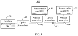
- a data transmission mode of a wireless communications system 900 in which one BBU supports two cascaded RRUs is used as an example for description.
- a BBU 90 receives downlink data sent by a gateway, processes the downlink data, and sends processed downlink data to an optical transceiver (optical transceiver) 93 through a common public radio interface (Common Public Radio Interface, CPRI), where the optical transceiver is also referred to as an optical module.
- CPRI Common Public Radio Interface
- the optical transceiver 93 converts the processed downlink data into a first downlink optical carrier signal, and sends, through an optical fiber, the first downlink optical carrier signal to an optical transceiver 94 that corresponds to an RRU 91; the optical transceiver 94 converts the first downlink optical carrier signal into a first downlink electrical signal, and sends the first downlink electrical signal to the RRU 91; the RRU 91 selectively receives part of the first downlink electrical signal, sends the remaining signal to an optical transceiver 95; the optical transceiver 95 converts the remaining signal into a second downlink optical carrier signal, and sends the second downlink optical carrier signal to an optical transceiver 96 through an optical fiber; the optical transceiver 96 converts the second downlink optical carrier signal into a second downlink electrical signal, and sends the second downlink electrical signal to an RRU 92.
- the downlink data received from the gateway can be sent to a mobile terminal by using the RRU 91 and the RRU 92
- the RRU 91 and the RRU 92 separately receive uplink data sent by the mobile terminal, and process the uplink data to obtain an uplink electrical signal.
- the RRU 92 sends an obtained first uplink electrical signal to the optical transceiver 96 that corresponds to the RRU 92;
- the optical transceiver 96 converts the first uplink electrical signal into a first uplink optical carrier signal, and sends, through an optical fiber, the first uplink optical carrier signal to the optical transceiver 95 that corresponds to the RRU 91;
- the optical transceiver 95 converts the first uplink optical carrier signal into a second uplink electrical signal, and sends the second uplink electrical signal to the RRU 91;
- the RRU 91 integrates the second uplink electrical signal with the uplink electrical signal obtained by the RRU 91 to obtain a third uplink electrical signal, and sends the third uplink electrical signal to the optical transceiver 94 connected to the RRU 91;
- the optical transceiver 94 converts the third
- the RRU 91 needs to forward data sent to or from the RRU 92, and when the RRU 91 is faulty, the RRU 92 cannot work.
- the existing networking structure of a distributed base station has the following disadvantages: when an RRU (referred to as a current RRU) of cascaded RRUs is faulty, a next RRU cannot work, which reduces system reliability.
- US 2007/0206950 A1 discloses a system for converting optical signals to MWOF signals for transmission to wireless data, audio and/or video terminals in the W-band.
- a centralized station performs the complex processing.
- a wavelength multiplexed signal is transmitted through a fiber.
- Optical filters selectively allow certain channels to be received by the respective remote stations.
- the optical filters can be a splitter and the optical filters pass the desired wavelengths at each remote station.
- the number of splitters and remote stations is greater than 2.
- embodiments of the present invention provide a wireless communications system and a wireless radio frequency apparatus, which resolve a technical problem of low system reliability caused by that when an RRU of multiple cascaded RRU is faulty in an existing distributed base station architecture, a next RRU cannot work.
- optical signals of different RRUs are transmitted by using different wavelengths (which includes transmission from an RRU to a BBU, and transmission from a BBU to an RRU), and correspondingly, optical transceivers of the cascaded RRUs work at different wavelengths.
- an optical splitter is further provided, and the optical transceivers of these cascaded RRUs are all connected to the optical splitter, and are connected to a same optical fiber by the optical splitter.
- optical signals of multiple RRUs that are transmitted on the optical fiber can be transmitted to the optical transceivers of all the RRUs by using the optical splitter, and each optical transceiver receives only a signal corresponding to its own operating wavelength; therefore, each RRU can correctly receive its own signal, and when an RRU is faulty, operation of the other RRUs is not affected, which greatly increases system reliability, and resolves the technical problem of low system reliability caused by that when a remote radio unit of multiple cascaded remote radio units is faulty in an existing distributed base station architecture, all next RRUs cannot work.
- each RRU receives its own signal without the need to forward a signal of another RRU, which reduces a requirement on bandwidth of a CPRI interface and reduces costs, and does not cause any limitation to a quantity of levels of cascaded RRUs. Further, each RRU no longer needs to be provided with two CPRI interfaces, thereby further reducing the costs. In addition, a decrease in the requirement on the bandwidth of the CPRI interface further reduces a requirement on a rate of an optical transceiver, which further reduces the costs.
- cascading of multiple RRUs is a common networking manner; however, for this networking manner, a current RRU sends data to a next RRU in a forwarding manner, and when the current RRU is faulty, all next RRUs cannot work, which results in reduced system reliability.
- optical signals of different RRUs are transmitted by using different wavelengths (which includes transmission from an RRU to a BBU, and transmission from a BBU to an RRU), and correspondingly, optical transceivers of the cascaded RRUs work at different wavelengths.
- an optical splitter is further provided, and the optical transceivers of these cascaded RRUs are all connected to the optical splitter, and are connected to a same optical fiber by the optical splitter.
- optical signals of multiple RRUs that are transmitted on the optical fiber can be transmitted to the optical transceivers of all the RRUs by using the optical splitter, and each optical transceiver receives only a signal corresponding to its own operating wavelength; therefore, each RRU can correctly receive its own signal, and when an RRU is faulty, working of the other RRUs is not affected, which greatly increases system reliability.
- each RRU receives its own signal without the need to forward a signal of another RRU, which reduces the requirement on the bandwidth of the CPRI interface and reduces the costs, and does not cause any limitation to the quantity of levels of cascaded RRUs. Further, each RRU no longer needs to be provided with two CPRI interfaces, thereby further reducing the costs. In addition, a decrease in the requirement on the bandwidth of the CPRI interface further reduces the requirement on the rate of the optical transceiver, which further reduces the costs.
- FIG. 1 is a schematic structural diagram of a wireless communications system 100 according to an embodiment of the present invention.
- the wireless communications system 100 includes: a baseband processing unit 10, an optical multiplexer 20, optical transceivers 31 and 32, and a wireless radio frequency apparatus 500, where the wireless radio frequency apparatus 500 includes remote radio units 41 and 42, optical transceivers 51 and 52, and an optical splitter 60.
- the baseband processing unit 10 is referred to as a BBU for short, with a full name being Baseband Control Unit, and is also referred to as a baseband control unit.
- the BBU 10 may include a transmission subsystem, a baseband subsystem, a control subsystem, and a power supply module.
- the transmission subsystem is configured to implement a function of transmitting and receiving data, and includes an interface between the BBU and a core network/controller and an interface between the BBU and a radio frequency module, where the interface between the BBU and the radio frequency module may be a common public radio interface (Common Public Radio Interface, CPRI) interface or an OBSAI (Open Base Station Architecture Initiative) interface.
- CPRI Common Public Radio Interface
- OBSAI Open Base Station Architecture Initiative
- the BBU 10 includes two interfaces, that is, a quantity of interfaces is the same as a quantity of remote radio units 40.
- the power supply module is configured to provide required power supply for the BBU 10.
- the baseband subsystem is mainly configured to implement a baseband processing function for uplink and downlink data, and mainly includes an uplink processing module and a downlink processing module.
- the uplink processing module is configured to demodulate and decode uplink baseband data from the transmission subsystem, and transmit decoded and demodulated data through the transmission subsystem;
- the downlink processing module is configured to modulate and encode downlink baseband data from the transmission subsystem, and transmit modulated and encoded data through the transmission subsystem.
- the control subsystem is configured to manage the entire wireless communications system 100, and the control subsystem may have, for example, one or more of the following functions: operation and maintenance functions such as device management, configuration management, alarm management, software management, and debugging and testing management; a signaling processing function such as logical resource management; clock module functions such as phase locking a GPS clock, performing frequency dividing, phase locking and phase adjustment, and providing a clock, which meets a requirement, for an entire base station.
- operation and maintenance functions such as device management, configuration management, alarm management, software management, and debugging and testing management
- a signaling processing function such as logical resource management
- clock module functions such as phase locking a GPS clock, performing frequency dividing, phase locking and phase adjustment, and providing a clock, which meets a requirement, for an entire base station.
- the remote radio unit is referred to as a RRU for short, with a full name being Radio Remote Unit.
- the RRU is configured to send, to an antenna feeder and by means of transmission filtering, a downlink baseband signal that is received from the BBU 10 and has undergone frequency conversion, filtering, radio frequency filtering, and passed a linear power amplifier, or perform filtering, low noise amplification, further radio frequency small signal amplification and filtering, down-conversion, analog-to-digital conversion, digital intermediate frequency processing, and the like on an uplink signal received from a mobile terminal.
- Each RRU is communicatively connected to the BBU 10 by using one interface.
- the optical multiplexer 20 is referred to as an optical MUX for short, with a full name being optical multiplexer.
- the optical multiplexer 20 is a device that combines and separates several optical carrier signals having different wavelengths, and may combine several optical carrier signals having different wavelengths onto one optical fiber for transmission, or separate optical carrier signals into multiple optical carrier signals according to the wavelengths to transmit the multiple optical carrier signals through multiple optical fibers.
- the optical multiplexer 20 generally includes multiple input interfaces and one output interface. In this implementation manner, the optical multiplexer 20 includes two input interfaces and one output interface, where both the input interfaces and the output interface are single-core bidirectional interfaces. In another implementation manner, the interfaces may be dual-core bidirectional interfaces.
- optical transceiver whose full name in English is optical transceiver is also referred to as an optical module, and is configured to implement optical/electrical conversion, where the optical/electrical conversion mentioned herein includes conversion from an optical signal to an electrical signal, and also includes conversion from an electrical signal to an optical signal.
- the optical transceivers 31 and 32 are provided between the BBU 10 and the optical multiplexer 20, where the optical transceiver 31 is connected to one input interface of the optical multiplexer 20 and one CPRI interface of the BBU 10, and the optical transceiver 32 is connected to another input interface of the optical multiplexer 20 and another CPRI interface of the BBU 10.
- the optical transceivers 51 and 52 are connected to the RRUs 41 and 42, respectively, that is, the optical transceiver 51 is connected to the RRU 41, and the optical transceiver 52 is connected to the RRU 42.
- An optical transceiver generally includes an optoelectronic device, a functional circuit, an optical interface, and the like, where the optoelectronic device includes an emitting part and a receiving part.
- the emitting part is implemented as follows: after an electrical signal with a particular bit rate is input and processed by an internal driver chip, a semiconductor laser device (LD) or a light-emitting diode (LED) is driven to emit a modulated optical signal having a corresponding rate, where an automatic optical power control circuit is provided inside the optoelectronic device, so as to keep power of the output optical signal steady.
- LD semiconductor laser device
- LED light-emitting diode
- the receiving part is implemented as follows: after an optical signal with a particular bit rate is input into the module, the optical signal is converted into an electrical signal by a photodetection diode; and a head amplifier amplifies the electrical signal and outputs an electrical signal with a corresponding bit rate.
- a function of the optical transceiver is optical/electrical conversion.
- Each optical transceiver connected to the BBU 10 is corresponding to one RRU, and at each RRU, one optical transceiver corresponding to the RRU is provided.
- Operating wavelengths of optical transceivers corresponding to a same RRU match each other, and operating wavelengths of optical transceivers corresponding to different RRUs are different, for example, operating wavelengths of the optical transceivers 31 and 51 corresponding to the RRU 41 match each other, and operating wavelengths of the optical transceivers 32 and 52 corresponding to the RRU 42 match each other, but the operating wavelengths of the optical transceivers 31 and 32 are different, and the operating wavelengths of the optical transceivers 51 and 52 are different, thereby ensuring that the optical transceiver corresponding to each RRU receives only a signal corresponding to its own operating wavelength.
- That operating wavelengths match each other mentioned herein refers to that a transmit wavelength of one optical transceiver is the same as a receive wavelength of another optical transceiver, so that the another optical transceiver can receive an optical signal sent by the optical transceiver.
- a transmit wavelength of the optical transceiver 31 is equal to a receive wavelength of the optical transceiver 51; and a receive wavelength of the optical transceiver 31 is equal to a transmit wavelength of the optical transceiver 51.
- a transmit wavelength of the optical transceiver 32 is equal to a receive wavelength of the optical transceiver 52; and a receive wavelength of the optical transceiver 32 is equal to a transmit wavelength of the optical transceiver 52.
- the foregoing optical transceivers may be dual-core bidirectional optical transceivers, or may be single-core bidirectional optical transceivers.
- each optical transceiver has one operating wavelength, which is not only used for transmission, but also used for reception;
- each optical transceiver has two operating wavelengths, including a transmit wavelength and a receive wavelength.
- the optical transceivers are single-core bidirectional optical transceivers, that is, transmission and reception are combined to be performed on one optical fiber, where different wavelengths are used to transmit and receive optical signals.
- the transmit wavelength of the optical transceiver 31 is ⁇ 1, and the receive wavelength of the optical transceiver 31 is ⁇ 2, where ⁇ 2 is unequal to ⁇ 1.
- the transmit wavelength of the optical transceiver 32 is ⁇ 3, and the receive wavelength of the optical transceiver 32 is ⁇ 4, where ⁇ 4 is unequal to ⁇ 3.
- the transmit wavelength ⁇ 1 of the optical transceiver 31 is different from the transmit wavelength ⁇ 3 of the optical transceiver 32
- the receive wavelength ⁇ 2 of the optical transceiver 31 is different from the receive wavelength ⁇ 4 of the optical transceiver 32, so as to ensure that optical signals sent out by different optical transceivers can be received by different RRUs.
- the transmit wavelength ⁇ 1 and the receive wavelength ⁇ 2 of the optical transceiver 31 are different, and the transmit wavelength ⁇ 3 and the receive wavelength ⁇ 4 of the optical transceiver 32 are different; therefore, ⁇ 1, ⁇ 2, ⁇ 3, and ⁇ 4 are different from each other.
- the optical transceiver 51 and the optical transceiver 31 are used in a paired manner, and the optical transceiver 52 and the optical transceiver 32 are used in a paired manner; therefore, when the transmit wavelength of the optical transceiver 31 is ⁇ 1, and the receive wavelength of the optical transceiver 31 is ⁇ 2, the receive wavelength of the optical transceiver 51 is ⁇ 1, and the transmit wavelength of the optical transceiver 51 is ⁇ 2; when the transmit wavelength of the optical transceiver 32 is ⁇ 3, and the receive wavelength of the optical transceiver 32 is ⁇ 4, the receive wavelength of the optical transceiver 52 is ⁇ 3, and the transmit wavelength of the optical transceiver 52 is ⁇ 4, where ⁇ 1, ⁇ 2, ⁇ 3, and ⁇ 4 are different from each other.
- the optical transceivers 51 and 52 are connected, by the optical splitter 60, to an optical fiber 70 that is connected to the optical multiplexer 20.
- the optical transceivers 51 and 52 may be connected to the optical splitter 60 by using an optical fiber, for example, a single-core bidirectional optical fiber.
- the optical multiplexer 20 may be also connected to the optical splitter 60 by using an optical fiber, for example, a single-core bidirectional optical fiber. Compared with using a dual-core bidirectional optical fiber, using the single-core bidirectional optical fiber reduces costs.
- the optical splitter 60 is also referred to as an optical splitting device, is one of important passive devices on an optical fiber link, and is configured to perform coupling, splitting, and distribution of an optical signal. Quantities of input and output interfaces of the optical splitter 60 may be selected according to a need. As shown in FIG. 1 , in this implementation manner, a quantity of RRUs is two, a quantity of optical splitters 60 is one, and a quantity of optical multiplexers 20 is one, and in this case, the optical splitter 60 is a 1:2 optical splitter. Alternatively, as shown in FIG. 3 or FIG.
- each RRU is connected to the optical splitter 60 by one optical transceiver, and the optical splitter 60 is also a 1:2 optical splitter. Because the 1:2 optical splitter has a small volume and can be directly placed in a maintenance cavity of the RRU, costs of mounting are reduced.
- the quantity of RRUs is two
- a quantity of interfaces of BBUs 10 is also two
- a quantity of optical transceivers connected to the BBUs 10 is also two
- one optical transceiver is provided between each RRU and the optical splitter.
- the BBU 10 and the optical multiplexer 20 may be placed in an equipment room, and the RRUs 41 and 42 may be remotely placed at an outdoor station by using an optical fiber.
- the optical transceiver 31 is mounted on an interface 11, corresponding to the RRU 41, of the BBU 10
- the optical transceiver 32 is mounted on an interface 12, corresponding to the RRU 42, of the BBU 10.
- the optical transceiver 51 is mounted on the RRU 41
- the optical transceiver 52 is mounted on the RRU 42.
- the optical splitter 60 may be independently provided, or may be provided in a maintenance cavity of the RRU 41.
- the BBU 10 modulates and encodes downlink baseband data, and sends modulated and encoded downlink data to the optical transceivers 31 and 32 through the interface 11 and the interface 12; the optical transceivers 31 and 32 convert the received downlink data into optical carrier signals having different wavelengths, and send the optical carrier signals to the optical multiplexer 20; and the optical multiplexer 20 combines the optical carrier signals from the optical transceivers 31 and 32 onto one optical fiber, so as to send the optical carrier signals to the optical splitter 60 though the optical fiber.
- the optical transceivers 51 and 52 connected to the optical splitter 60 selectively receive, according to the wavelengths, data corresponding to the wavelengths.
- the receive wavelength of the optical transceiver 51 is equal to the transmit wavelength of the optical transceiver 31, and the optical transceiver 51 can receive only data sent by the optical transceiver 31 to the optical multiplexer 20; the receive wavelength of the optical transceiver 52 is equal to the transmit wavelength of the optical transceiver 32, and the optical transceiver 52 can receive only data sent by the optical transceiver 32 to the optical multiplexer 20.
- the two optical transceivers 51 and 52 send the downlink electrical signals to the RRUs 41 and 42, respectively; and the RRUs 41 and 42 transmit the received signals to an antenna feeder by means of transmission filtering after the received signals undergoes radio frequency filtering and passes a linear power amplifier.
- the RRUs 41 and 42 perform filtering, low noise amplification, further radio frequency small signal amplification and filtering, down-conversion, analog-to-digital conversion, digital intermediate frequency processing, and the like on an uplink signal received from a mobile terminal to generate uplink electrical signals, and transmit the uplink electrical signals to the optical transceivers 51 and 52, respectively; and the optical transceivers 51 and 52 convert the received uplink electrical signals into uplink optical carrier signals.
- the optical transceivers 51 and 52 have different transmit wavelengths, where a transmit wavelength of the optical transceiver 51 is equal to the receive wavelength of the optical transceiver 31, so that data sent by the optical transceiver 51 can be only received by the optical transceiver 31; and a transmit wavelength of the optical transceiver 52 is equal to the receive wavelength of the optical transceiver 32, so that data sent by the optical transceiver 52 can be only received by the optical transceiver 32.
- the optical splitter 60 couples the received two links of uplink optical carrier signals onto a same downlink optical fiber, and sends the signals to the optical multiplexer 20; the optical multiplexer 20 separates the received optical carrier signals, and separately sends the separated optical carrier signals to the optical transceivers 31 and 32; the optical transceivers 31 and 32 convert the received optical carrier signals into uplink data signals, and send the uplink data signals to corresponding interfaces of the BBU 10; and the BBU 10 demodulates and decodes the received uplink data signals, and transmits demodulated and decoded uplink data signals to a gateway.
- a signal of the RRU 42 can be directly transmitted to the optical splitter 60, and transferred to the BBU 10 by using the optical splitter 60, and a signal of the BBU 10 can also be transmitted to the RRU 42 by using the optical splitter 60, thereby ensuring that the RRU 42 can work normally.
- an optical splitter 60 is provided between two RRUs, that is, a first RRU 41 and a second RRU 42, and even when the first RRU 41 is faulty, a signal of the second RRU 42 can be directly transmitted to the optical splitter 60, and transferred to a BBU 10 by using the optical splitter 60; and a signal of the BBU 10 can also be transmitted to the second RRU 42 by using the optical splitter 60, thereby ensuring that the RRU 42 can work normally, which resolves a technical problem of low system reliability caused by that when a remote radio unit of multiple cascaded RRUs is faulty in an existing distributed base station architecture, all next RRUs cannot work.
- all links use different wavelengths for communication, and are completely independent of each other, which also resolves a technical problem that when multiple RRUs are cascaded, a rate of an optical transceiver increases and a quantity of cascaded RRUs on a same link is limited because communication bandwidth is superimposed.
- this application further provides a wireless communications system 200.
- the wireless communications system 200 is different from the wireless communications system 100 in that: a quantity of optical transceivers and a quantity of RRUs are different, and an optical splitter is different.
- a quantity of RRUs 40 is M, correspondingly, M optical transceivers 50 are separately connected to the M RRUs 40, and M optical transceivers 30 are provided on M interfaces between a BBU 10 and the M RRUs 40.
- An optical splitter 60 may be a 1:N optical splitter, where M is an integer greater than or equal to 3, and N is an integer greater than or equal to 2.
- the M RRUs 40 are separately connected to the optical splitter 60 by the M optical transceivers 50.
- N is equal to M
- the optical splitter 60 is a 1:M optical splitter and has M+1 interfaces, where a quantity of optical splitters is one. In this case, all the RRUs 40 are connected the optical splitter 60.
- N may be unequal to M, for example, when N is equal to 2, the optical splitter 60 is a 1:2 optical splitter and has three interfaces, where a quantity of optical splitters is M-1.
- One interface of a first optical splitter is connected to an optical multiplexer 20 by an optical fiber, so as to receive multiple links of optical signals that are obtained by the optical multiplexer 20 by means of combining, and the other two interfaces are separately connected to the first RRU 40 and the second optical splitter; one interface of the ith optical splitter is connected to the (i-1)th optical splitter, and the other two interfaces are separately connected to the ith RRU and the (i+1)th optical splitter, where 2 ⁇ i ⁇ M-2; one interface of the last optical splitter, that is, the (M-1)th optical splitter, is connected to the (M-2)th optical splitter, and the other two interfaces are separately connected to the (M-1)th RRU and the Mth RRU.
- the operating principle of the foregoing wireless communications system 200 is the same as that of the wireless communications system 100, and the details are not described herein again.
- signals of the other RRUs can be directly transmitted to the optical splitter 60, and transferred to the BBU 10 by using the optical splitter 60, and a signal of the BBU 10 can also be transmitted to the other RRUs 40 by using the optical splitter 60, thereby ensuring that the other RRUs 40 can work normally, which resolves a technical problem of low system reliability caused by that when an RRU of multiple cascaded RRUs is faulty in an existing distributed base station architecture, all next RRUs cannot work.
- all links use different wavelengths for communication, and are completely independent of each other, which also resolves a technical problem that when multiple RRUs are cascaded, a rate of an optical transceiver increases and a quantity of cascaded RRUs on a same link is limited because communication bandwidth is superimposed.
- FIG. 3 is a schematic structural diagram of a wireless communications system 300 according to another embodiment of the present invention.
- the wireless communications system 300 is different from the wireless communications system 100 in FIG. 1 in that: a quantity of optical splitters 60 is two, and a quantity of RRUs 40 is three, and correspondingly, a quantity of interfaces of a BBU 10 is also three, a quantity of optical transceivers 30 connected to the BBU 10 is three, and a quantity of optical transceivers 50 connected to the RRUs 40 is also three.
- the quantity of optical splitters 60 is one less than the quantity of RRUs 40, that is, there are two optical splitters 60, which are optical transceivers 61 and 62.
- the optical splitter 61 is connected to an optical multiplexer 20 and the optical splitter 62, an RRU 41 is connected to the optical splitter 61 by an optical transceiver 51, an RRU 42 is connected to the optical splitter 62 by an optical transceiver 52, and an RRU 43 is connected to the optical splitter 62 by an optical transceiver 53.
- the BBU 10 and the optical multiplexer 20 are placed in an equipment room, and the three RRUs 40 may be remotely placed at an outdoor station by using an optical fiber.
- An optical transceiver 31 is mounted on an interface 11, corresponding to the first RRU 41, of the BBU 10; an optical transceiver 32 is mounted on an interface 12, corresponding to the second RRU 42, of the BBU 10; an optical transceiver 33 is mounted on an interface 13, corresponding to the third RRU 43, of the BBU 10.
- the optical transceiver 51 is mounted on the RRU 41, the optical transceiver 52 is mounted on the RRU 42, and the optical transceiver 53 is mounted on the RRU 43.
- the optical splitter 61 is placed in a maintenance cavity of the remote radio unit 41, and the optical splitter 62 is placed in a maintenance cavity of the RRU 42.
- the BBU 10 modulates and encodes downlink baseband data, and sends modulated and encoded downlink data to the optical transceivers 31, 32 and 33 through the interface 11, the interface 12, and the interface 13; the optical transceivers 31, 32 and 33 convert the received downlink data into optical carrier signals having different wavelengths, and send the optical carrier signals to the optical multiplexer 20; and the optical multiplexer 20 combines the received optical carrier signals onto one optical fiber, and sends the optical carrier signals to the three optical transceivers 50 through the optical splitters 60; and the three optical transceivers 50 selectively receive, according to the wavelengths, data corresponding to the wavelengths.
- a receive wavelength of the optical transceiver 51 is equal to a transmit wavelength of the optical transceiver 31, and the optical transceiver 51 can receive only data sent by the optical transceiver 31;
- a receive wavelength of the optical transceiver 52 is equal to a transmit wavelength of the optical transceiver 32, and the optical transceiver 52 can receive only data sent by the optical transceiver 32;
- a receive wavelength of the optical transceiver 53 is equal to a transmit wavelength of the optical transceiver 33, and the optical transceiver 53 can receive only data sent by the optical transceiver 33.
- the three optical transceivers 50 After converting the received signals into downlink electrical signals, the three optical transceivers 50 send the downlink electrical signals to the three RRUs 40, and the three RRUs 40 sends the received signals to an antenna feeder by means of transmission filtering after the signals undergoes radio frequency filtering and passes a linear power amplifier.
- the three RRUs 40 perform filtering, low noise amplification, further radio frequency small signal amplification and filtering, down-conversion, analog-to-digital conversion, digital intermediate frequency processing, and the like on an uplink signal received from a mobile terminal to generate uplink electrical signals, and transmit the uplink electrical signals to the three optical transceivers 50; and the three optical transceivers 50 convert the received uplink electrical signals into uplink optical carrier signals.
- the three optical transceivers 50 have different transmit wavelengths, where a transmit wavelength of the optical transceiver 51 is equal to a receive wavelength of the optical transceiver 31, and data sent by the optical transceiver 51 can be only received by the optical transceiver 31; a transmit wavelength of the optical transceiver 52 is equal to a receive wavelength of the optical transceiver 32, and data sent by the optical transceiver 52 can be only received by the optical transceiver 32; and a transmit wavelength of the optical transceiver 53 is equal to a receive wavelength of the optical transceiver 33, and data sent by the optical transceiver 53 can be only received by the optical transceiver 33.
- the optical splitters 61 and 62 couple the three links of uplink optical carrier signals onto a same downlink optical fiber, and send the signals to the optical multiplexer 20; the optical multiplexer 20 separates the received optical carrier signals, and separately sends the separated optical carrier signals to the optical transceivers 31 32, and 33; after separately converting the received optical carrier signals into uplink data signals, the optical transceivers 31, 32, and 33 send the uplink data signals to the corresponding three interfaces 11, 12, and 13 of the BBU 10, respectively; and the BBU 10 demodulates and decodes the received uplink data signals, and transmits demodulated and decoded uplink data signals to a gateway.
- optical signals of different RRUs are transmitted by using different wavelengths, and correspondingly, optical transceivers of the cascaded RRUs work at different wavelengths.
- Optical splitters are further provided, and the optical transceivers of these cascaded RRUs are all connected to the optical splitters, and are connected to a same optical fiber 70 by the optical splitters.
- the optical signals of the multiple RRUs that are transmitted on the optical fiber can be transmitted to the optical transceivers of all the RRUs by using the optical splitters, and each optical transceiver receives only a signal corresponding to its own operating wavelength; therefore, each RRU can correctly receive its own signal, and when an RRU is faulty, operation of the other RRUs is not affected.
- signals of the RRUs 42 and 43 can be directly transferred to the BBU 10 by using the optical splitter 61, and a signal of the BBU 10 can also be transmitted to the RRU 42 and the RRU 43 by using the optical splitter 61, thereby ensuring that the RRUs 42 and 43 can work normally.
- the RRU 43 can transfer a signal to the BBU 10 by using the optical splitters 62 and 61, and a signal of the BBU 10 can also be transferred to the RRU 43 by using the optical splitters 61 and 62, which resolves a technical problem of low system reliability caused by that when an RRU of multiple cascaded RRUs is faulty in an existing distributed base station architecture, all next RRUs cannot work.
- all links use different wavelengths for communication, and are completely independent of each other, which also resolves a technical problem that when multiple RRUs are cascaded, a rate of an optical transceiver increases and a quantity of cascaded RRUs on a same link is limited because communication bandwidth is superimposed.
- FIG. 4 is a schematic structural diagram of a wireless communications system 400 according to still another embodiment of the present invention.
- the wireless communications system 400 is different from the wireless communications system 100 in FIG. 2 in that: a quantity of RRUs 40, a quantity of optical splitters 60, and a quantity of optical transceivers 50 are different.
- the quantity of RRUs 40 is M, where M is greater than 3; correspondingly, M optical transceivers 50 are separately connected to the M RRUs, and M optical transceivers 30 are provided on M interfaces between a BBU 10 and the M RRUs 40.
- the optical splitter 60 is a 1:2 optical splitter, and the quantity of optical splitters 60 is M-1, where the M-1 optical splitters 60 are cascaded by using a single-core optical fiber 70.
- One interface of the first optical splitter 60 is connected to an optical multiplexer 20 by the optical fiber 70, so as to receive multiple links of optical signals that are obtained by the optical multiplexer 20 by means of combining, and the other two interfaces are separately connected to the first RRU 40 and the second optical splitter 60; one interface of the ith optical splitter 60 is connected to the (i-1)th optical splitter 60, and the other two interfaces are separately connected to the ith RRU and the (i+1)th optical splitter 60, where 2 ⁇ i ⁇ M-2; one interface of the last optical splitter 60, that is, the (M-1)th optical splitter 60, is connected to the (M-2)th optical splitter 60, and the other two interfaces are separately connected to the (M-1)th RRU 40 and the Mth RRU 40.
- the BBU 10 and the optical multiplexer 20 may be placed in an equipment room, and the M RRUs 40 may be remotely placed at an outdoor station by using an optical fiber.
- the first optical transceiver 30 is mounted on an interface 1, corresponding to the first RRU 40, of the BBU 10; the jth optical transceiver 30 is mounted on an interface j, corresponding to the jth RRU, of the BBU 10, where 1 ⁇ j ⁇ M; the Mth optical transceiver 30 is mounted on an interface M, corresponding to the Mth RRU 40, of the BBU 10.
- the first optical transceiver 50 is mounted on the first RRU 40
- the jth optical transceiver is mounted on the jth RRU 40, where 1 ⁇ j ⁇ M
- the Mth optical transceiver 50 is mounted on the Mth RRU 40.
- the first optical splitter 60 may be placed in a maintenance cavity of the first RRU 40
- the ith optical splitter 60 may be placed in a maintenance cavity of the ith RRU 40, where 2 ⁇ i ⁇ M-2
- the (M-1)th optical splitter 60 may be placed in a maintenance cavity of the (M-1)th RRU 40.
- this embodiment is not limited thereto, and the optical splitters 60 may be placed independently, or placed in another manner.
- the BBU 10 modulates and encodes downlink baseband data, and sends modulated and encoded downlink data to the M optical transceivers 30; the M optical transceivers 30 convert the received downlink data into optical carrier signals having different wavelengths, and send the optical carrier signals to the optical multiplexer 20; the optical multiplexer 20 combines the received optical carrier signals onto one optical fiber, and sends the optical carrier signals to the M optical transceivers 50 through the optical splitters 60; and the M optical transceivers 50 selectively receive, according to the wavelengths, data sent to the M optical transceivers.
- the M optical transceivers 50 After separately converting the received signals into downlink electrical signals, the M optical transceivers 50 send the downlink electrical signals to the M RRUs 40; and the M RRUs 40 separately transmit the received signals to an antenna feeder by means of transmission filtering after the received signals undergoes radio frequency filtering and passes a linear power amplifier.
- the M RRUs 40 perform filtering, low noise amplification, further radio frequency small signal amplification and filtering, down-conversion, analog-to-digital conversion, digital intermediate frequency processing, and the like on an uplink signal received from a mobile terminal to generate uplink electrical signals, and transmit the uplink electrical signals to the M optical transceivers 50 correspondingly; and the M optical transceivers 50 separately convert the received uplink electrical signals into uplink optical carrier signals and send the uplink optical carrier signals to the optical splitters 60.
- the M optical transceivers 50 have different transmit wavelengths.
- Each optical transceiver 50 has one optical transceiver 30 matching the optical transceiver 50, that is, a transmit wavelength of each optical transceiver 50 is equal to a receive wavelength of one optical transceiver 30, and data sent by the optical transceiver 50 can only be received by the optical transceiver.
- the optical splitters 60 couple M links of uplink optical carrier signals onto a same downlink optical fiber, and send the signals to the optical multiplexer 20; the optical multiplexer 20 separates the received optical carrier signals, and sends the separated optical carrier signals separately to the M optical transceivers 30; the M optical transceivers 30 convert the received optical carrier signals into uplink data signals, and send the uplink data signals to the BBU 10; and the BBU 10 demodulates and decodes the received uplink data signals, and transmits demodulated and decoded uplink data signals to a gateway.
- optical signals of different RRUs are transmitted by using different wavelengths, and correspondingly, optical transceivers of the cascaded RRUs work at different wavelengths.
- Optical splitters are further provided, and the optical transceivers of these cascaded RRUs are all connected to the optical splitters, and are connected to a same optical fiber by the optical splitters.
- the optical signals of the multiple RRUs that are transmitted on the optical fiber can be transmitted to the optical transceivers of all the RRUs by using the optical splitters, and each optical transceiver receives only a signal corresponding to its own operating wavelength; therefore, each RRU can correctly receive its own signal, and when an RRU is faulty, operation of the other RRUs is not affected.
- signals of the other RRUs can be directly transferred to the BBU 10 by using the optical splitters 60, and a signal of the BBU 10 can also be transmitted to the other RRUs by using the optical splitters 60, thereby ensuring that the other RRUs can work normally, which resolves a technical problem of low system reliability caused by that when an RRU of multiple cascaded RRUs is faulty in an existing distributed base station architecture, all next RRUs cannot work.
- all links use different wavelengths for communication, and are completely independent of each other, which also resolves a technical problem that when multiple RRUs are cascaded, a rate of an optical transceiver increases and a quantity of cascaded RRUs on a same link is limited because communication bandwidth is superimposed.
- this application further provides a wireless radio frequency apparatus, where the wireless radio frequency apparatus includes:
- the optical splitter is a 1:N optical splitter, where N is an integer greater than or equal to 2 and less than or equal to M.
- the optical splitter is a 1:2 optical splitter, and a quantity of optical splitters is M-1.
- the M-1 optical splitters are connected to each other by a single-core optical fiber.
- the optical fiber is a single-core optical fiber.
- an operating wavelength of each optical transceiver of the first optical transceivers and the second optical transceivers includes a receive wavelength and a transmit wavelength.
- optical signals of different RRUs are transmitted by using different wavelengths (which includes transmission from an RRU to a BBU, and transmission from a BBU to an RRU), and correspondingly, optical transceivers of the cascaded RRUs work at different wavelengths.
- an optical splitter is further provided, and the optical transceivers of these cascaded RRUs are all connected to the optical splitter, and are connected to a same optical fiber by the optical splitter.
- optical signals of multiple RRUs that are transmitted on the optical fiber can be transmitted to the optical transceivers of all the RRUs by using the optical splitter, and each optical transceiver receives only a signal corresponding to its own operating wavelength; therefore, each RRU can correctly receive its own signal, and when an RRU is faulty, operation of the other RRUs is not affected, which greatly increases system reliability.
- each RRU receives its own signal without the need to forward a signal of another RRU, which reduces the requirement on the bandwidth of the CPRI and reduces the costs, and does not cause any limitation to the quantity of levels of cascaded RRUs. Further, each RRU no longer needs to be provided with two CPRI interfaces, thereby further reducing the costs. In addition, a decrease in the requirement on the bandwidth of the CPRI interface further reduces the requirement on the rate of the optical transceiver, which further reduces the costs.
- Embodiment 1 A wireless radio frequency apparatus, wherein the wireless radio frequency apparatus comprises:
- Embodiment 2 The apparatus according to embodiment 1, wherein the optical splitter is a 1:N optical splitter, and N is an integer greater than or equal to 2 and less than or equal to M.
- Embodiment 3 The apparatus according to embodiment 2, wherein the optical splitter is a 1:2 optical splitter, and a quantity of optical splitters is M-1.
- Embodiment 4 The apparatus according to embodiment 3, wherein when M is greater than 2, the M-1 optical splitters are connected to each other by a single-core optical fiber.
- Embodiment 5 The apparatus according to any one of embodiments 1 to 4, wherein the optical fiber is a single-core optical fiber.
- Embodiment 6 The apparatus according to any one of embodiments 1 to 5, wherein an operating wavelength of each optical transceiver of the first optical transceivers and the second optical transceivers comprises a receive wavelength and a transmit wavelength.
- Embodiment 7 A wireless communications system, wherein the wireless communications system comprises:
- Embodiment 8 The wireless communications system according to embodiment 7, wherein the optical splitter is a 1:N optical splitter, and N is an integer greater than or equal to 2 and less than or equal to M.
- Embodiment 9 The wireless communications system according to embodiment 8, wherein the optical splitter is a 1:2 optical splitter, and a quantity of optical splitters is M-1.
- Embodiment 10 The wireless communications system according to embodiment 9, wherein when M is greater than 2, the M-1 optical splitters are connected to each other by a single-core optical fiber.
- Embodiment 11 The wireless communications system according to any one of embodiments 7 to 10, wherein the optical fiber is a single-core optical fiber.
- Embodiment 12 The wireless communications system according to any one of embodiments 7 to 11, wherein an operating wavelength of each optical transceiver of the first optical transceivers and the second optical transceivers comprises a receive wavelength and a transmit wavelength.
- Embodiment 13 The system according to embodiment 12, wherein that an operating wavelength of a first optical transceiver matches an operating wavelength of a second optical transceiver corresponding to the first optical transceiver comprises that: in the first optical transceiver and the second optical transceiver corresponding to the first optical transceiver, the transmit wavelength of the first optical transceiver is the same as the receive wavelength of the second optical transceiver; and the receive wavelength of the first optical transceiver is the same as the transmit wavelength of the second optical transceiver.
Landscapes
- Physics & Mathematics (AREA)
- Engineering & Computer Science (AREA)
- Computer Networks & Wireless Communication (AREA)
- Signal Processing (AREA)
- Electromagnetism (AREA)
- General Physics & Mathematics (AREA)
- Optics & Photonics (AREA)
- Optical Communication System (AREA)
Claims (9)
- Vorrichtung umfasst M-1 optische Splitter (60) und M erste optische Sendeempfänger (50), wobei M eine ganze Zahl größer oder gleich 2 ist und sich Betriebswellenlängen der M ersten optischen Sendeempfänger (50) voneinander unterscheiden und die M-1 optischen Splitter (60) optische 1:2-Splitter sind und drei Schnittstellen aufweisen, wobei:eine Schnittstelle eines ersten optischen Splitters (60) ausgelegt ist zum Empfangen von mehreren Links von optischen Signalen und die anderen zwei Schnittstellen separat mit dem ersten optischen Sendeempfänger (50) der M ersten optischen Sendeempfänger (50) und einem zweiten optischen Splitter (60) verbunden sind;eine Schnittstelle des i-ten optischen Splitters (60) mit dem (i-1)-ten optischen Splitter (60) verbunden ist und die anderen zwei Schnittstellen separat mit dem i-ten optischen Sendeempfänger (50) der M ersten optischen Sendeempfänger (50) und dem (i+1)-ten optischen Splitter (60) verbunden sind, wobei 2≤i≤M-2;eine Schnittstelle des (M-1)-ten optischen Splitters (60) mit dem (M-2)-ten optischen Splitter (60) verbunden ist und die anderen zwei Schnittstellen separat mit dem (M-1)-ten optischen Sendeempfänger (50) und dem M-ten optischen Sendeempfänger (50) der M ersten optischen Sendeempfänger (50) verbunden sind; unddie M ersten optischen Sendeempfänger (50) bidirektionale optische Einzelkern-Sendeempfänger sind und die Betriebswellenlänge jedes ersten optischen Sendeempfängers (50) eine Sendewellenlänge und eine Empfangswellenlänge umfasst, die unterschiedlich sind und die jeweils zum Senden und Empfangen von optischen Signalen verwendet werden.
- Vorrichtung nach Anspruch 1, wobei M größer als 2 ist, die M-1 optischen Splitter (60) durch eine optische Einzelkernfaser miteinander verbunden sind.
- Vorrichtung nach einem der Ansprüche 1 oder 2, die ferner Folgendes umfasst:einen optischen Multiplexer (20), der mit der Schnittstelle, die zum Empfangen der mehreren Links von optischen Signalen ausgelegt ist und zu dem ersten optischen Splitter (60) gehört, über eine optische Faser (70) verbunden ist, und Bereitstellen der mehreren Links von optischen Signalen an die Schnittstelle, undM zweite optische Sendeempfänger (30), die M ersten optischen Sendeempfängern (50) entsprechen und mit dem optischen Multiplexer (20) verbunden sind, wobei sich Betriebswellenlängen der M zweiten optischen Sendeempfänger (30) voneinander unterscheiden und für den entsprechenden ersten optischen Sendeempfänger (50) und den zweiten optischen Sendeempfänger (30) eine Betriebswellenlänge des ersten optischen Sendeempfängers (50) mit einer Betriebswellenlänge des zweiten optischen Sendeempfängers (30) übereinstimmt.
- Vorrichtung nach Anspruch 3, wobei die M zweiten optischen Sendeempfänger (30) bidirektionale optische Einzelkern-Sendeempfänger sind und die Betriebswellenlänge jedes zweiten optischen Sendeempfängers (30) eine Sendewellenlänge und eine Empfangswellenlänge umfasst, die unterschiedlich sind und die jeweils zum Senden und Empfangen von optischen Signalen verwendet werden.
- Vorrichtung nach Anspruch 4, wobei für den entsprechenden ersten optischen Sendeempfänger (50) und den zweiten optischen Sendeempfänger (30) eine Sendewellenlänge des ersten optischen Sendeempfängers (50) gleich der Empfangswellenlänge des zweiten optischen Sendeempfängers (30) ist; und die Empfangswellenlänge des ersten optischen Sendeempfängers (50) gleich der Sendewellenlänge des zweiten optischen Sendeempfängers (30) ist.
- Drahtlosfunkfrequenzeinrichtung, die Folgendes umfasst:eine Vorrichtung nach einem der Ansprüche 1 bis 5;M Fernfunkeinheiten (40), die separat mit den M ersten optischen Sendeempfängern (50) in der Vorrichtung verbunden sind.
- Einrichtung nach Anspruch 6, wobei jeder optische Splitter (60) in einem Wartungshohlraum einer entsprechenden Fernfunkeinheit (40) platziert ist.
- Drahtloskommunikationssystem, das Folgendes umfasst:eine Vorrichtung nach einem der Ansprüche 3 bis 5;M Fernfunkeinheiten (40), die separat mit den M ersten optischen Sendeempfängern (50) in der Vorrichtung verbunden sind; undeine Basisbandverarbeitungseinheit (10), die mit den M zweiten optischen Sendeempfängern (30) in der Vorrichtung verbunden ist.
- Einrichtung nach Anspruch 8, wobei jeder optische Splitter (60) in einem Wartungshohlraum einer entsprechenden Fernfunkeinheit (40) platziert ist.
Priority Applications (1)
| Application Number | Priority Date | Filing Date | Title |
|---|---|---|---|
| EP18185234.4A EP3457595B1 (de) | 2014-04-29 | 2014-04-29 | Drahtloskommunikationssystem und drahtlosfunkfrequenzvorrichtung |
Applications Claiming Priority (3)
| Application Number | Priority Date | Filing Date | Title |
|---|---|---|---|
| EP18185234.4A EP3457595B1 (de) | 2014-04-29 | 2014-04-29 | Drahtloskommunikationssystem und drahtlosfunkfrequenzvorrichtung |
| EP14890981.5A EP3139525B1 (de) | 2014-04-29 | 2014-04-29 | Drahtloskommunikationssystem und funkfrequenzvorrichtung |
| PCT/CN2014/076503 WO2015165046A1 (zh) | 2014-04-29 | 2014-04-29 | 无线通信系统和无线射频装置 |
Related Parent Applications (1)
| Application Number | Title | Priority Date | Filing Date |
|---|---|---|---|
| EP14890981.5A Division EP3139525B1 (de) | 2014-04-29 | 2014-04-29 | Drahtloskommunikationssystem und funkfrequenzvorrichtung |
Publications (2)
| Publication Number | Publication Date |
|---|---|
| EP3457595A1 EP3457595A1 (de) | 2019-03-20 |
| EP3457595B1 true EP3457595B1 (de) | 2024-10-09 |
Family
ID=51808350
Family Applications (2)
| Application Number | Title | Priority Date | Filing Date |
|---|---|---|---|
| EP18185234.4A Active EP3457595B1 (de) | 2014-04-29 | 2014-04-29 | Drahtloskommunikationssystem und drahtlosfunkfrequenzvorrichtung |
| EP14890981.5A Active EP3139525B1 (de) | 2014-04-29 | 2014-04-29 | Drahtloskommunikationssystem und funkfrequenzvorrichtung |
Family Applications After (1)
| Application Number | Title | Priority Date | Filing Date |
|---|---|---|---|
| EP14890981.5A Active EP3139525B1 (de) | 2014-04-29 | 2014-04-29 | Drahtloskommunikationssystem und funkfrequenzvorrichtung |
Country Status (7)
| Country | Link |
|---|---|
| US (2) | US10270530B2 (de) |
| EP (2) | EP3457595B1 (de) |
| JP (1) | JP6522659B2 (de) |
| KR (1) | KR102006964B1 (de) |
| CN (2) | CN109818675B (de) |
| ES (1) | ES2690389T3 (de) |
| WO (1) | WO2015165046A1 (de) |
Families Citing this family (10)
| Publication number | Priority date | Publication date | Assignee | Title |
|---|---|---|---|---|
| EP3457595B1 (de) * | 2014-04-29 | 2024-10-09 | Huawei Technologies Co., Ltd. | Drahtloskommunikationssystem und drahtlosfunkfrequenzvorrichtung |
| EP3332579B1 (de) * | 2015-08-06 | 2019-10-09 | Telefonaktiebolaget LM Ericsson (PUBL) | Kommunikationsnetzsteuerung |
| US10637602B2 (en) * | 2016-07-15 | 2020-04-28 | Safe-Com Wireless | Method, apparatus and system to amplify and transport analog signals |
| KR102054180B1 (ko) * | 2016-11-29 | 2020-01-22 | 한국전자통신연구원 | 대용량의 데이터 트래픽을 지원하는 분산형 안테나 시스템을 위한 리모트 라디오 헤드 장치 및 호스트 장치 |
| WO2018133932A1 (en) * | 2017-01-18 | 2018-07-26 | Telefonaktiebolaget Lm Ericsson (Publ) | Node for a fronthaul network and monitoring of optical trasceivers in fronthaul networks |
| CN110611514B (zh) * | 2019-09-20 | 2022-05-17 | 内蒙古信元网络安全技术股份有限公司 | 分布式接收机的信号解调系统、方法及计算机存储介质 |
| CN113572525B (zh) * | 2020-04-28 | 2022-11-04 | 华为技术有限公司 | 一种通信方法及系统 |
| CN115801125A (zh) * | 2021-09-10 | 2023-03-14 | 合圣科技股份有限公司 | 无线射频转换系统及一对多分配装置 |
| EP4480209A4 (de) * | 2022-02-16 | 2025-03-19 | Huawei Technologies Co., Ltd. | Systeme und verfahren zur energieeinsparung in einem sende-empfangspunkt (trp) |
| CN116929436A (zh) * | 2023-09-13 | 2023-10-24 | 宁德时代新能源科技股份有限公司 | 测试系统及方法 |
Citations (1)
| Publication number | Priority date | Publication date | Assignee | Title |
|---|---|---|---|---|
| US20070206950A1 (en) * | 2006-03-03 | 2007-09-06 | Lucent Technologies, Inc. | Method and apparatus for generating and transmitting WDM MWOF signals |
Family Cites Families (32)
| Publication number | Priority date | Publication date | Assignee | Title |
|---|---|---|---|---|
| JP3568145B2 (ja) * | 1998-05-25 | 2004-09-22 | 株式会社エヌ・ティ・ティ・ドコモ | 光波長多重を用いる高周波の光ファイバ伝送システム |
| JP2003324393A (ja) | 2002-02-26 | 2003-11-14 | Matsushita Electric Ind Co Ltd | 双方向光伝送システム並びにそれに用いられる親局及び子局 |
| US7200342B2 (en) * | 2002-06-06 | 2007-04-03 | The Aerospace Corporation | Direct-sequence spread-spectrum optical-frequency-shift-keying code-division-multiple-access communication system |
| JP2004363948A (ja) * | 2003-06-04 | 2004-12-24 | Nippon Telegr & Teleph Corp <Ntt> | 光ネットワークシステムおよび光送受信装置 |
| US8958697B2 (en) * | 2003-06-10 | 2015-02-17 | Alexander I. Soto | System and method for optical layer management in optical modules and remote control of optical modules |
| US8374508B2 (en) * | 2003-06-12 | 2013-02-12 | Alexander I Soto | Augmenting passive optical networks |
| JP2005012447A (ja) * | 2003-06-18 | 2005-01-13 | Nippon Telegr & Teleph Corp <Ntt> | 光送受信装置および光伝送システム |
| JP2005094263A (ja) * | 2003-09-16 | 2005-04-07 | Panasonic Mobile Communications Co Ltd | 固定無線通信用光リモートシステムならびにそれに用いられるセンタ局装置、リモート局装置および通信方法 |
| US7609971B1 (en) * | 2004-12-06 | 2009-10-27 | The United States Of America As Represented By The Secretary Of The Army | Electro optical scanning multi-function antenna |
| JP4852260B2 (ja) * | 2005-05-16 | 2012-01-11 | 三菱電機株式会社 | 1心双方向波長多重伝送システム |
| ATE531149T1 (de) * | 2006-06-02 | 2011-11-15 | Aurora Networks Inc | Wdm-transport von mit unterträgern multiplexten signalen über eine optische faser in spektralbereichen mit geringer streuung |
| CN101098206B (zh) * | 2006-06-26 | 2012-05-02 | 华为技术有限公司 | 一种无源光网络系统及其光路处理方法 |
| CN101166041B (zh) * | 2006-10-18 | 2011-06-22 | 中兴通讯股份有限公司 | 无线通讯系统中的射频远端分布系统 |
| CN101232345A (zh) * | 2008-01-04 | 2008-07-30 | 中兴通讯股份有限公司 | 一种射频单元与基站之间的信号传输方法及系统 |
| CN101350662B (zh) * | 2008-09-01 | 2010-06-23 | 成都优博创技术有限公司 | 基于波分复用(xWDM)射频拉远单元的级联组网方法 |
| US8532489B2 (en) * | 2009-03-04 | 2013-09-10 | Futurewei Technologies, Inc. | Multi-fiber ten gigabit passive optical network optical line terminal for optical distribution network coexistence with gigabit passive optical network |
| CN101841748B (zh) * | 2009-03-17 | 2013-06-12 | 中国移动通信集团公司 | 信号传输系统以及相关装置 |
| JP2010245987A (ja) * | 2009-04-09 | 2010-10-28 | Nippon Telegr & Teleph Corp <Ntt> | 光/無線アクセスシステム |
| CN101995616B (zh) * | 2009-08-19 | 2012-05-23 | 中国科学院半导体研究所 | 全硅基材料多通道光收发模块 |
| CN102065343B (zh) * | 2009-11-16 | 2013-10-02 | 华为技术有限公司 | 波长选择方法、装置及系统 |
| CN102360106A (zh) * | 2011-10-31 | 2012-02-22 | 索尔思光电(成都)有限公司 | 一种单纤双向收发模块及其封装 |
| US9100121B2 (en) * | 2011-06-30 | 2015-08-04 | Electronics And Telecommunications Research Institute | Link setup method for wavelength division multiplexing wavelength passive optical network(WDM PON) system |
| CN102984604A (zh) | 2011-09-02 | 2013-03-20 | 中兴通讯股份有限公司 | 数据交互系统及方法 |
| US9184842B2 (en) * | 2011-10-06 | 2015-11-10 | Telefonaktiebolaget L M Ericsson (Publ) | Apparatus for communicating a plurality of antenna signals at different optical wavelengths |
| CN202374404U (zh) * | 2011-12-22 | 2012-08-08 | 深圳国人通信有限公司 | 多业务无源光网络系统 |
| US9374187B2 (en) * | 2012-03-12 | 2016-06-21 | Advanced Rf Technologies, Inc. | Distributed antenna system and method |
| CN102710361B (zh) * | 2012-06-01 | 2015-09-30 | 华为技术有限公司 | 一种分布式基站信号传输系统及通信系统 |
| CN104718795B (zh) * | 2012-10-19 | 2018-05-29 | 日本电信电话株式会社 | 分散式无线通信基站系统、信号处理装置、无线装置和分散式无线通信基站系统的执行方法 |
| WO2014136264A1 (ja) * | 2013-03-08 | 2014-09-12 | 富士通株式会社 | 光ネットワークシステムおよび光通信方法 |
| US9225453B2 (en) * | 2013-04-09 | 2015-12-29 | Futurewei Technologies, Inc. | Optimizing optical systems using code division multiple access and/or orthogonal frequency-division multiplexing |
| EP3457595B1 (de) * | 2014-04-29 | 2024-10-09 | Huawei Technologies Co., Ltd. | Drahtloskommunikationssystem und drahtlosfunkfrequenzvorrichtung |
| US9236949B1 (en) * | 2014-06-24 | 2016-01-12 | Applied Optoelectronics, Inc. | Laser transceiver with improved bit error rate |
-
2014
- 2014-04-29 EP EP18185234.4A patent/EP3457595B1/de active Active
- 2014-04-29 EP EP14890981.5A patent/EP3139525B1/de active Active
- 2014-04-29 ES ES14890981.5T patent/ES2690389T3/es active Active
- 2014-04-29 CN CN201811511084.XA patent/CN109818675B/zh active Active
- 2014-04-29 CN CN201480000671.6A patent/CN104137454B/zh active Active
- 2014-04-29 JP JP2016565453A patent/JP6522659B2/ja active Active
- 2014-04-29 KR KR1020167032719A patent/KR102006964B1/ko active Active
- 2014-04-29 WO PCT/CN2014/076503 patent/WO2015165046A1/zh not_active Ceased
-
2016
- 2016-10-31 US US15/338,557 patent/US10270530B2/en active Active
-
2019
- 2019-03-19 US US16/357,739 patent/US10826610B2/en active Active
Patent Citations (1)
| Publication number | Priority date | Publication date | Assignee | Title |
|---|---|---|---|---|
| US20070206950A1 (en) * | 2006-03-03 | 2007-09-06 | Lucent Technologies, Inc. | Method and apparatus for generating and transmitting WDM MWOF signals |
Also Published As
| Publication number | Publication date |
|---|---|
| US10270530B2 (en) | 2019-04-23 |
| EP3139525B1 (de) | 2018-08-15 |
| US20190215068A1 (en) | 2019-07-11 |
| WO2015165046A1 (zh) | 2015-11-05 |
| EP3139525A1 (de) | 2017-03-08 |
| JP2017517198A (ja) | 2017-06-22 |
| CN104137454B (zh) | 2019-01-08 |
| JP6522659B2 (ja) | 2019-05-29 |
| EP3457595A1 (de) | 2019-03-20 |
| US10826610B2 (en) | 2020-11-03 |
| KR20160145808A (ko) | 2016-12-20 |
| US20170047996A1 (en) | 2017-02-16 |
| CN109818675A (zh) | 2019-05-28 |
| ES2690389T3 (es) | 2018-11-20 |
| CN109818675B (zh) | 2022-04-22 |
| KR102006964B1 (ko) | 2019-08-02 |
| EP3139525A4 (de) | 2017-05-03 |
| CN104137454A (zh) | 2014-11-05 |
Similar Documents
| Publication | Publication Date | Title |
|---|---|---|
| EP3457595B1 (de) | Drahtloskommunikationssystem und drahtlosfunkfrequenzvorrichtung | |
| US10567974B2 (en) | Monitoring non-supported wireless spectrum within coverage areas of distributed antenna systems (DASS) | |
| TWI514791B (zh) | 射頻信號收發裝置及方法,自我監控光學傳輸裝置及方法 | |
| US9236941B2 (en) | System for implementing a radio over fiber transmission in a passive optical network | |
| JP5894094B2 (ja) | 分散型無線通信基地局システム、olt部、及びonu部 | |
| US10110310B2 (en) | Transmission system and transmission method | |
| JP2014110574A (ja) | 光無線アクセスシステム | |
| EP4425796A1 (de) | Erste vorrichtung, zweite vorrichtung, signalübertragungsverfahren und drahtloses zugangssystem | |
| KR101577758B1 (ko) | 아날로그 분산 안테나 시스템에서의 중계 장치 | |
| JP6899856B2 (ja) | 無線通信システムおよび無線ラジオ周波数装置 | |
| US11716147B2 (en) | Optical communication device and optical communication system including the same | |
| EP4557637A1 (de) | Vorrichtung zur signalverstärkung sowie vorrichtung und verfahren zum empfangen eines optischen signals | |
| US10454582B2 (en) | Transponder for a radio-over-fibre transmission system allowing retransmission from the antenna management interface | |
| KR101175002B1 (ko) | 이동통신 중계기 및 이동통신 중계기용 리모트 |
Legal Events
| Date | Code | Title | Description |
|---|---|---|---|
| PUAI | Public reference made under article 153(3) epc to a published international application that has entered the european phase |
Free format text: ORIGINAL CODE: 0009012 |
|
| STAA | Information on the status of an ep patent application or granted ep patent |
Free format text: STATUS: THE APPLICATION HAS BEEN PUBLISHED |
|
| AC | Divisional application: reference to earlier application |
Ref document number: 3139525 Country of ref document: EP Kind code of ref document: P |
|
| AK | Designated contracting states |
Kind code of ref document: A1 Designated state(s): AL AT BE BG CH CY CZ DE DK EE ES FI FR GB GR HR HU IE IS IT LI LT LU LV MC MK MT NL NO PL PT RO RS SE SI SK SM TR |
|
| STAA | Information on the status of an ep patent application or granted ep patent |
Free format text: STATUS: REQUEST FOR EXAMINATION WAS MADE |
|
| 17P | Request for examination filed |
Effective date: 20190920 |
|
| RBV | Designated contracting states (corrected) |
Designated state(s): AL AT BE BG CH CY CZ DE DK EE ES FI FR GB GR HR HU IE IS IT LI LT LU LV MC MK MT NL NO PL PT RO RS SE SI SK SM TR |
|
| STAA | Information on the status of an ep patent application or granted ep patent |
Free format text: STATUS: EXAMINATION IS IN PROGRESS |
|
| 17Q | First examination report despatched |
Effective date: 20211004 |
|
| GRAJ | Information related to disapproval of communication of intention to grant by the applicant or resumption of examination proceedings by the epo deleted |
Free format text: ORIGINAL CODE: EPIDOSDIGR1 |
|
| GRAP | Despatch of communication of intention to grant a patent |
Free format text: ORIGINAL CODE: EPIDOSNIGR1 |
|
| GRAP | Despatch of communication of intention to grant a patent |
Free format text: ORIGINAL CODE: EPIDOSNIGR1 |
|
| STAA | Information on the status of an ep patent application or granted ep patent |
Free format text: STATUS: GRANT OF PATENT IS INTENDED |
|
| INTG | Intention to grant announced |
Effective date: 20240516 |
|
| GRAS | Grant fee paid |
Free format text: ORIGINAL CODE: EPIDOSNIGR3 |
|
| GRAA | (expected) grant |
Free format text: ORIGINAL CODE: 0009210 |
|
| STAA | Information on the status of an ep patent application or granted ep patent |
Free format text: STATUS: THE PATENT HAS BEEN GRANTED |
|
| AC | Divisional application: reference to earlier application |
Ref document number: 3139525 Country of ref document: EP Kind code of ref document: P |
|
| AK | Designated contracting states |
Kind code of ref document: B1 Designated state(s): AL AT BE BG CH CY CZ DE DK EE ES FI FR GB GR HR HU IE IS IT LI LT LU LV MC MK MT NL NO PL PT RO RS SE SI SK SM TR |
|
| REG | Reference to a national code |
Ref country code: CH Ref legal event code: EP |
|
| REG | Reference to a national code |
Ref country code: DE Ref legal event code: R096 Ref document number: 602014091007 Country of ref document: DE |
|
| REG | Reference to a national code |
Ref country code: IE Ref legal event code: FG4D |
|
| REG | Reference to a national code |
Ref country code: LT Ref legal event code: MG9D |
|
| REG | Reference to a national code |
Ref country code: NL Ref legal event code: MP Effective date: 20241009 |
|
| REG | Reference to a national code |
Ref country code: AT Ref legal event code: MK05 Ref document number: 1731726 Country of ref document: AT Kind code of ref document: T Effective date: 20241009 |
|
| PG25 | Lapsed in a contracting state [announced via postgrant information from national office to epo] |
Ref country code: NL Free format text: LAPSE BECAUSE OF FAILURE TO SUBMIT A TRANSLATION OF THE DESCRIPTION OR TO PAY THE FEE WITHIN THE PRESCRIBED TIME-LIMIT Effective date: 20241009 |
|
| PG25 | Lapsed in a contracting state [announced via postgrant information from national office to epo] |
Ref country code: NL Free format text: LAPSE BECAUSE OF FAILURE TO SUBMIT A TRANSLATION OF THE DESCRIPTION OR TO PAY THE FEE WITHIN THE PRESCRIBED TIME-LIMIT Effective date: 20241009 |
|
| PG25 | Lapsed in a contracting state [announced via postgrant information from national office to epo] |
Ref country code: HR Free format text: LAPSE BECAUSE OF FAILURE TO SUBMIT A TRANSLATION OF THE DESCRIPTION OR TO PAY THE FEE WITHIN THE PRESCRIBED TIME-LIMIT Effective date: 20241009 Ref country code: PT Free format text: LAPSE BECAUSE OF FAILURE TO SUBMIT A TRANSLATION OF THE DESCRIPTION OR TO PAY THE FEE WITHIN THE PRESCRIBED TIME-LIMIT Effective date: 20250210 Ref country code: IS Free format text: LAPSE BECAUSE OF FAILURE TO SUBMIT A TRANSLATION OF THE DESCRIPTION OR TO PAY THE FEE WITHIN THE PRESCRIBED TIME-LIMIT Effective date: 20250209 |
|
| PG25 | Lapsed in a contracting state [announced via postgrant information from national office to epo] |
Ref country code: FI Free format text: LAPSE BECAUSE OF FAILURE TO SUBMIT A TRANSLATION OF THE DESCRIPTION OR TO PAY THE FEE WITHIN THE PRESCRIBED TIME-LIMIT Effective date: 20241009 |
|
| PG25 | Lapsed in a contracting state [announced via postgrant information from national office to epo] |
Ref country code: BG Free format text: LAPSE BECAUSE OF FAILURE TO SUBMIT A TRANSLATION OF THE DESCRIPTION OR TO PAY THE FEE WITHIN THE PRESCRIBED TIME-LIMIT Effective date: 20241009 |
|
| PG25 | Lapsed in a contracting state [announced via postgrant information from national office to epo] |
Ref country code: ES Free format text: LAPSE BECAUSE OF FAILURE TO SUBMIT A TRANSLATION OF THE DESCRIPTION OR TO PAY THE FEE WITHIN THE PRESCRIBED TIME-LIMIT Effective date: 20241009 |
|
| PG25 | Lapsed in a contracting state [announced via postgrant information from national office to epo] |
Ref country code: NO Free format text: LAPSE BECAUSE OF FAILURE TO SUBMIT A TRANSLATION OF THE DESCRIPTION OR TO PAY THE FEE WITHIN THE PRESCRIBED TIME-LIMIT Effective date: 20250109 |
|
| PG25 | Lapsed in a contracting state [announced via postgrant information from national office to epo] |
Ref country code: GR Free format text: LAPSE BECAUSE OF FAILURE TO SUBMIT A TRANSLATION OF THE DESCRIPTION OR TO PAY THE FEE WITHIN THE PRESCRIBED TIME-LIMIT Effective date: 20250110 Ref country code: LV Free format text: LAPSE BECAUSE OF FAILURE TO SUBMIT A TRANSLATION OF THE DESCRIPTION OR TO PAY THE FEE WITHIN THE PRESCRIBED TIME-LIMIT Effective date: 20241009 Ref country code: AT Free format text: LAPSE BECAUSE OF FAILURE TO SUBMIT A TRANSLATION OF THE DESCRIPTION OR TO PAY THE FEE WITHIN THE PRESCRIBED TIME-LIMIT Effective date: 20241009 |
|
| PG25 | Lapsed in a contracting state [announced via postgrant information from national office to epo] |
Ref country code: PL Free format text: LAPSE BECAUSE OF FAILURE TO SUBMIT A TRANSLATION OF THE DESCRIPTION OR TO PAY THE FEE WITHIN THE PRESCRIBED TIME-LIMIT Effective date: 20241009 |
|
| PGFP | Annual fee paid to national office [announced via postgrant information from national office to epo] |
Ref country code: GB Payment date: 20250306 Year of fee payment: 12 |
|
| PG25 | Lapsed in a contracting state [announced via postgrant information from national office to epo] |
Ref country code: RS Free format text: LAPSE BECAUSE OF FAILURE TO SUBMIT A TRANSLATION OF THE DESCRIPTION OR TO PAY THE FEE WITHIN THE PRESCRIBED TIME-LIMIT Effective date: 20250109 |
|
| PG25 | Lapsed in a contracting state [announced via postgrant information from national office to epo] |
Ref country code: SM Free format text: LAPSE BECAUSE OF FAILURE TO SUBMIT A TRANSLATION OF THE DESCRIPTION OR TO PAY THE FEE WITHIN THE PRESCRIBED TIME-LIMIT Effective date: 20241009 |
|
| PGFP | Annual fee paid to national office [announced via postgrant information from national office to epo] |
Ref country code: DE Payment date: 20250305 Year of fee payment: 12 |
|
| PG25 | Lapsed in a contracting state [announced via postgrant information from national office to epo] |
Ref country code: DK Free format text: LAPSE BECAUSE OF FAILURE TO SUBMIT A TRANSLATION OF THE DESCRIPTION OR TO PAY THE FEE WITHIN THE PRESCRIBED TIME-LIMIT Effective date: 20241009 |
|
| REG | Reference to a national code |
Ref country code: DE Ref legal event code: R097 Ref document number: 602014091007 Country of ref document: DE |
|
| PG25 | Lapsed in a contracting state [announced via postgrant information from national office to epo] |
Ref country code: EE Free format text: LAPSE BECAUSE OF FAILURE TO SUBMIT A TRANSLATION OF THE DESCRIPTION OR TO PAY THE FEE WITHIN THE PRESCRIBED TIME-LIMIT Effective date: 20241009 |
|
| PG25 | Lapsed in a contracting state [announced via postgrant information from national office to epo] |
Ref country code: RO Free format text: LAPSE BECAUSE OF FAILURE TO SUBMIT A TRANSLATION OF THE DESCRIPTION OR TO PAY THE FEE WITHIN THE PRESCRIBED TIME-LIMIT Effective date: 20241009 |
|
| PG25 | Lapsed in a contracting state [announced via postgrant information from national office to epo] |
Ref country code: SK Free format text: LAPSE BECAUSE OF FAILURE TO SUBMIT A TRANSLATION OF THE DESCRIPTION OR TO PAY THE FEE WITHIN THE PRESCRIBED TIME-LIMIT Effective date: 20241009 |
|
| PG25 | Lapsed in a contracting state [announced via postgrant information from national office to epo] |
Ref country code: CZ Free format text: LAPSE BECAUSE OF FAILURE TO SUBMIT A TRANSLATION OF THE DESCRIPTION OR TO PAY THE FEE WITHIN THE PRESCRIBED TIME-LIMIT Effective date: 20241009 |
|
| PG25 | Lapsed in a contracting state [announced via postgrant information from national office to epo] |
Ref country code: IT Free format text: LAPSE BECAUSE OF FAILURE TO SUBMIT A TRANSLATION OF THE DESCRIPTION OR TO PAY THE FEE WITHIN THE PRESCRIBED TIME-LIMIT Effective date: 20241009 |
|
| PLBE | No opposition filed within time limit |
Free format text: ORIGINAL CODE: 0009261 |
|
| STAA | Information on the status of an ep patent application or granted ep patent |
Free format text: STATUS: NO OPPOSITION FILED WITHIN TIME LIMIT |
|
| PG25 | Lapsed in a contracting state [announced via postgrant information from national office to epo] |
Ref country code: SE Free format text: LAPSE BECAUSE OF FAILURE TO SUBMIT A TRANSLATION OF THE DESCRIPTION OR TO PAY THE FEE WITHIN THE PRESCRIBED TIME-LIMIT Effective date: 20241009 |
|
| 26N | No opposition filed |
Effective date: 20250710 |
|
| REG | Reference to a national code |
Ref country code: CH Ref legal event code: H13 Free format text: ST27 STATUS EVENT CODE: U-0-0-H10-H13 (AS PROVIDED BY THE NATIONAL OFFICE) Effective date: 20251125 |
|
| PG25 | Lapsed in a contracting state [announced via postgrant information from national office to epo] |
Ref country code: LU Free format text: LAPSE BECAUSE OF NON-PAYMENT OF DUE FEES Effective date: 20250429 |
|
| PG25 | Lapsed in a contracting state [announced via postgrant information from national office to epo] |
Ref country code: MC Free format text: LAPSE BECAUSE OF FAILURE TO SUBMIT A TRANSLATION OF THE DESCRIPTION OR TO PAY THE FEE WITHIN THE PRESCRIBED TIME-LIMIT Effective date: 20241009 |
|
| REG | Reference to a national code |
Ref country code: BE Ref legal event code: MM Effective date: 20250430 |
|
| PG25 | Lapsed in a contracting state [announced via postgrant information from national office to epo] |
Ref country code: FR Free format text: LAPSE BECAUSE OF NON-PAYMENT OF DUE FEES Effective date: 20250430 |
|
| PG25 | Lapsed in a contracting state [announced via postgrant information from national office to epo] |
Ref country code: BE Free format text: LAPSE BECAUSE OF NON-PAYMENT OF DUE FEES Effective date: 20250430 |
|
| PG25 | Lapsed in a contracting state [announced via postgrant information from national office to epo] |
Ref country code: CH Free format text: LAPSE BECAUSE OF NON-PAYMENT OF DUE FEES Effective date: 20250430 |