EP3457009A1 - Dampfturbine mit wellendichtungsanordnung - Google Patents
Dampfturbine mit wellendichtungsanordnung Download PDFInfo
- Publication number
- EP3457009A1 EP3457009A1 EP18194984.3A EP18194984A EP3457009A1 EP 3457009 A1 EP3457009 A1 EP 3457009A1 EP 18194984 A EP18194984 A EP 18194984A EP 3457009 A1 EP3457009 A1 EP 3457009A1
- Authority
- EP
- European Patent Office
- Prior art keywords
- seal
- pressure chamber
- steam
- turbine
- pressure
- Prior art date
- Legal status (The legal status is an assumption and is not a legal conclusion. Google has not performed a legal analysis and makes no representation as to the accuracy of the status listed.)
- Granted
Links
Images
Classifications
-
- F—MECHANICAL ENGINEERING; LIGHTING; HEATING; WEAPONS; BLASTING
- F01—MACHINES OR ENGINES IN GENERAL; ENGINE PLANTS IN GENERAL; STEAM ENGINES
- F01D—NON-POSITIVE DISPLACEMENT MACHINES OR ENGINES, e.g. STEAM TURBINES
- F01D11/00—Preventing or minimising internal leakage of working-fluid, e.g. between stages
- F01D11/02—Preventing or minimising internal leakage of working-fluid, e.g. between stages by non-contact sealings, e.g. of labyrinth type
- F01D11/04—Preventing or minimising internal leakage of working-fluid, e.g. between stages by non-contact sealings, e.g. of labyrinth type using sealing fluid, e.g. steam
- F01D11/06—Control thereof
-
- F—MECHANICAL ENGINEERING; LIGHTING; HEATING; WEAPONS; BLASTING
- F16—ENGINEERING ELEMENTS AND UNITS; GENERAL MEASURES FOR PRODUCING AND MAINTAINING EFFECTIVE FUNCTIONING OF MACHINES OR INSTALLATIONS; THERMAL INSULATION IN GENERAL
- F16J—PISTONS; CYLINDERS; SEALINGS
- F16J15/00—Sealings
- F16J15/16—Sealings between relatively-moving surfaces
- F16J15/32—Sealings between relatively-moving surfaces with elastic sealings, e.g. O-rings
- F16J15/3284—Sealings between relatively-moving surfaces with elastic sealings, e.g. O-rings characterised by their structure; Selection of materials
- F16J15/3288—Filamentary structures, e.g. brush seals
-
- F—MECHANICAL ENGINEERING; LIGHTING; HEATING; WEAPONS; BLASTING
- F16—ENGINEERING ELEMENTS AND UNITS; GENERAL MEASURES FOR PRODUCING AND MAINTAINING EFFECTIVE FUNCTIONING OF MACHINES OR INSTALLATIONS; THERMAL INSULATION IN GENERAL
- F16J—PISTONS; CYLINDERS; SEALINGS
- F16J15/00—Sealings
- F16J15/16—Sealings between relatively-moving surfaces
- F16J15/40—Sealings between relatively-moving surfaces by means of fluid
-
- F—MECHANICAL ENGINEERING; LIGHTING; HEATING; WEAPONS; BLASTING
- F16—ENGINEERING ELEMENTS AND UNITS; GENERAL MEASURES FOR PRODUCING AND MAINTAINING EFFECTIVE FUNCTIONING OF MACHINES OR INSTALLATIONS; THERMAL INSULATION IN GENERAL
- F16J—PISTONS; CYLINDERS; SEALINGS
- F16J15/00—Sealings
- F16J15/44—Free-space packings
- F16J15/447—Labyrinth packings
- F16J15/4472—Labyrinth packings with axial path
-
- F—MECHANICAL ENGINEERING; LIGHTING; HEATING; WEAPONS; BLASTING
- F05—INDEXING SCHEMES RELATING TO ENGINES OR PUMPS IN VARIOUS SUBCLASSES OF CLASSES F01-F04
- F05D—INDEXING SCHEME FOR ASPECTS RELATING TO NON-POSITIVE-DISPLACEMENT MACHINES OR ENGINES, GAS-TURBINES OR JET-PROPULSION PLANTS
- F05D2220/00—Application
- F05D2220/30—Application in turbines
- F05D2220/31—Application in turbines in steam turbines
-
- F—MECHANICAL ENGINEERING; LIGHTING; HEATING; WEAPONS; BLASTING
- F05—INDEXING SCHEMES RELATING TO ENGINES OR PUMPS IN VARIOUS SUBCLASSES OF CLASSES F01-F04
- F05D—INDEXING SCHEME FOR ASPECTS RELATING TO NON-POSITIVE-DISPLACEMENT MACHINES OR ENGINES, GAS-TURBINES OR JET-PROPULSION PLANTS
- F05D2240/00—Components
- F05D2240/55—Seals
- F05D2240/56—Brush seals
Definitions
- the invention relates to a steam turbine with a sealing arrangement according to the preamble of the independent patent claim 1.
- the gap between the turbine housing and the turbine rotor protruding from the turbine housing must be sealed to prevent steam from escaping through the gap.
- a seal is arranged in the gap between the turbine housing and the turbine rotor.
- the seal can not completely seal the gap, so that always a certain mass flow of steam can escape through the gap.
- the steam turbine according to the invention with at least one turbine housing forming a first pressure chamber and a turbine rotor projecting through the turbine housing into a second pressure chamber and with a sealing arrangement for sealing a gap between a first pressure chamber and the second pressure chamber, the pressure P 1 in the first pressure chamber is greater than the pressure P 2 in the second pressure chamber, and wherein the seal assembly has at least one brush seal and a downstream in the flow direction of the seal assembly, facing away from the first pressure chamber labyrinth seal, characterized in that steam is removed from the Beschaufelungspfad downstream of the seal assembly and in a Gap between the brush seal and the labyrinth seal is initiated.
- the invention makes use of the fact that, in an array of brush seals in series with conventional labyrinth seals which serve as backup, the majority of the pressure difference P 1 -P 2 is attributable to the brush and only a small part to the backup mazes.
- An embodiment of the invention provides that the steam is removed via a collection groove introduced into the blading part of the steam turbine.
- the collecting groove can be produced easily in the turbine housing and enables a simple and streamlined discharge of the steam from the blading part of the steam turbine.
- a further embodiment of the invention provides that between the removal of the steam downstream of the seal assembly and the introduction of the steam in the space between the brush seal and the labyrinth seal a check valve and / or a control valve is arranged.
- a check valve and / or a control valve is arranged between the removal of the steam downstream of the seal assembly and the introduction of the steam in the space between the brush seal and the labyrinth seal.
- a valve must be installed in the supply line, which can be closed in this case.
- a non-return valve or a combination of control valve and non-return valve may be formed.
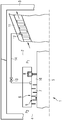
- the figure represents only a schematic diagram in which essentially only the components necessary for the invention are shown.
- the figure in no way shows a true-to-scale embodiment of the invention.
- the sole FIGURE shows a steam turbine 1 with at least one turbine housing 3 forming a first pressure chamber 2 and a turbine rotor 5 protruding through the turbine housing 3 into a second pressure chamber 4.
- the steam turbine 1 has a sealing arrangement 6 for sealing a gap 7 between the first pressure chamber 2 and the second pressure chamber 4th on.
- the pressure P 1 in the first pressure chamber 2 is greater than the pressure P 2 in the second pressure chamber 4.
- the seal assembly 6 comprises a brush seal 8 and a downstream in the flow direction of the seal assembly 6, facing away from the first pressure chamber 2 labyrinth seal 9. Downstream of the seal assembly 6 is Steam from the Beschaufelungspfad, preferably via an introduced in the blading part 11 of the steam turbine 1 collecting groove 12 taken.
- the collecting groove 12 is connected to a steam line 14, via which the steam from the annular groove 12 is introduced into a gap 10 between the brush seal 8 and the labyrinth seal 9. Since the steam is already relaxed in the region of the removal from the blading path, it has a lower temperature than immediately before the brush seal 8. The cooler steam introduced into the intermediate space flows through the labyrinth seal 9 and cools it. By cooling the labyrinth seal 9 an unacceptably high component temperature in the region of the seal assembly 6 is prevented. In normal steam turbine operation accounts for the majority of the pressure difference P 1 -P 2 on the brush seal 8 and only a small part of the pressure difference on trained as a backup labyrinth seal 9.
- a control valve 13 is arranged in the steam line 14.
- a non-return valve or a combination of control valve and non-return valve can be formed.
Landscapes
- Engineering & Computer Science (AREA)
- General Engineering & Computer Science (AREA)
- Mechanical Engineering (AREA)
- Turbine Rotor Nozzle Sealing (AREA)
- Sealing Using Fluids, Sealing Without Contact, And Removal Of Oil (AREA)
Abstract
Description
- Die Erfindung betrifft eine Dampfturbine mit einer Dichtungsanordnung nach dem Oberbegriff des unabhängigen Patentanspruchs 1.
- Bei Dampfturbinen muss der Spalt zwischen dem Turbinengehäuse und dem aus dem Turbinengehäuse hinausragenden Turbinenrotors abgedichtet werden, um zu verhindern, dass Dampf durch den Spalt entweichen kann. Hierzu wird eine Dichtung in den Spalt zwischen Turbinengehäuse und Turbinenrotor angeordnet. Die Dichtung kann den Spalt allerdings nicht vollständig abdichten, so dass immer ein gewisser Dampfmassenstrom durch den Spalt entweichen kann. Durch die Dampfreibung innerhalb der Dichtungsanordnung kommt es zu einer Temperaturerhöhung des zu dichtenden Mediums, wobei diese umso größer ist, je geringer bei sonst gleichen Bedingungen die Massenströme durch die Dichtung sind. Dies kann zu einer Gefährdung der Bauteile infolge zu hoher Bauteiltemperaturen führen. Besonders stark tritt dieser Effekt bei Dichtungen mit extrem niedrigen Leckagemassenströmen, wie beispielsweise Bürstendichtungen, die häufig bei Dampfturbinen zur Anwendung kommen, auf. Um unzulässig hohe Bauteiltemperaturen zu vermeiden, ist eine Reduzierung des Einsatzbereiches der Bauteile notwendig, oder es müssen Werkstoffe mit höherer Warmfestigkeit ausgewählt werden. Dies führt zu höheren Leckageverlusten und damit niedrigeren Wirkungsgraden bzw. oder zu einer Erhöhung der Bauteilkosten.
- Ausgehend zum zuvor beschriebenen Problem ist es Aufgabe der vorliegenden Erfindung, eine Dampfturbine bereitzustellen, welche eine verbesserte Dichtungsanordnung aufweist, wodurch unzulässig hohe Bauteiltemperaturen vermeiden werden.
- Die Aufgabe wird gelöst durch die Merkmale des unabhängigen Patentanspruchs 1.
- Weitere Vorteile und Ausgestaltungen der Erfindung, die einzeln oder in Kombination miteinander verwendet werden können, sind Gegenstand der Unteransprüche.
- Die erfindungsgemäße Dampfturbine mit wenigstens einem, einen ersten Druckraum bildenden Turbinengehäuse und einem durch das Turbinengehäuse hindurch in einen zweiten Druckraum ragenden Turbinenrotor, sowie mit einer Dichtungsanordnung zum Abdichten eines Spaltes zwischen einem ersten Druckraum und dem zweiten Druckraum, wobei der Druck P1 im ersten Druckraum größer ist als der Druck P2 im zweiten Druckraum, und wobei die Dichtungsanordnung wenigstens eine Bürstendichtung und eine in Durchströmungsrichtung der Dichtungsanordnung nachgeordnete, zum ersten Druckraum abgewandte Labyrinthdichtung aufweist, zeichnet sich dadurch aus, dass Dampf dem Beschaufelungspfad stromabwärts der Dichtungsanordnung entnommen wird und in einen Zwischenraum zwischen der Bürstendichtung und der Labyrinthdichtung eingeleitet wird.
- Die Erfindung macht sich den Sachverhalt zunutze, dass in einer Anordnung von Bürstendichtungen in Reihe mit üblichen Labyrinthdichtungen, welche als Backup dienen, der überwiegende Teil der Druckdifferenz P1-P2 auf die Bürste und nur ein kleiner Teil auf die Backup Labyrinthe entfällt. Durch Einleiten von entspannten und daher kühlerem Dampf aus dem Beschaufelungspfad stromabwärts der Dichtungsanordnung in den Zwischenraum zwischen der Bürstendichtung und der Labyrinthdichtung wird die Labyrinthdichtung mit dem kühleren Dampf durchströmt und dadurch gekühlt. Hierdurch können unzulässig hohe Bauteiltemperaturen an der Dichtungsanordnung wirkungsvoll verhindert werden. Durch das Einleiten des kühleren Dampfes in den Zwischenraum zwischen der Bürstendichtung und der Labyrinthdichtung treten zwar zusätzliche Leckageverluste auf, diese sind aber bei geeigneter Auslegung geringer, als sie ohne den Einsatz der Bürstendichtung und nur mittels Labyrinthdichtungen wären. Beim Ausfall der Bürstendichtung übernimmt die Labyrinthdichtung die Aufgabe der Abdichtung des Spaltes zwischen dem Turbinengehäuse und dem Turbinenrotor.
- Eine Ausgestaltung der Erfindung sieht vor, dass der Dampf über ein im Beschaufelungsteil der Dampfturbine eingebrachte Sammelnut entnommen wird. Die Sammelnut lässt sich fertigungstechnisch einfach im Turbinengehäuse ausbilden und ermöglicht ein einfaches und strömungsgünstiges Abführen des Dampfes aus dem Beschaufelungsteil der Dampfturbine.
- Eine weitere Ausgestaltung der Erfindung sieht vor, dass zwischen der Entnahme des Dampfes stromabwärts der Dichtungsanordnung und der Einleitung des Dampfes in den Zwischenraum zwischen der Bürstendichtung und der Labyrinthdichtung eine Rückschlagklappe und/oder ein Regelventil angeordnet ist. Wie bereits weiter oben beschrieben, muss beim Ausfall der Bürstendichtung die Labyrinthdichtung die Dichtungsaufgabe übernehmen. Um in diesem Fall eine Rückströmung des Dampfes in den Beschaufelungspfad zu vermeiden, muss in die Zuleitung ein Ventil eingebaut werden, das in diesem Fall geschlossen werden kann. Alternativ kann auch eine Rückschlagklappe oder eine Kombination aus Regelventil und Rückschlagklappe ausgebildet sein.
- Nachfolgend werden die Erfindung sowie weitere Vorteile der Erfindung anhand eines Ausführungsbeispieles erläutert.
- Die Abbildung stellt dabei nur eine Prinzipskizze dar, in der im Wesentlichen nur die zur Erfindung notwendigen Bauteile gezeigt werden. Die Abbildung zeigt keinesfalls eine maßstabsgetreue Ausbildung der Erfindung.
- Die einzige Figur zeigt eine Dampfturbine 1 mit wenigstens einem, einem ersten Druckraum 2 bildenden Turbinengehäuse 3 und einem durch das Turbinengehäuse 3 hindurch in einen zweiten Druckraum 4 ragenden Turbinenrotor 5. Die Dampfturbine 1 weist eine Dichtungsanordnung 6 zum Abdichten eines Spaltes 7 zwischen dem ersten Druckraum 2 und dem zweiten Druckraum 4 auf. Der Druck P1 im ersten Druckraum 2 ist dabei größer als der Druck P2 im zweiten Druckraum 4. Die Dichtungsanordnung 6 umfasst eine Bürstendichtung 8 sowie eine in Durchströmungsrichtung der Dichtungsanordnung 6 nachgeordnete, zum ersten Druckraum 2 abgewandte Labyrinthdichtung 9. Stromabwärts der Dichtungsanordnung 6 wird Dampf aus dem Beschaufelungspfad, vorzugsweise über eine im Beschaufelungsteil 11 der Dampfturbine 1 eingebrachte Sammelnut 12, entnommen. Die Sammelnut 12 ist mit einer Dampfleitung 14 verbunden, über die der Dampf aus der Ringnut 12 in einen Zwischenraum 10 zwischen der Bürstendichtung 8 und der Labyrinthdichtung 9 eingeleitet wird. Da der Dampf im Bereich der Entnahme aus dem Beschaufelungspfad bereits entspannt ist, weist er eine niedrigere Temperatur als unmittelbar vor der Bürstendichtung 8 auf. Der kühlere in den Zwischenraum eingeleitete Dampf durchströmt die Labyrinthdichtung 9 und kühlt sie dabei. Durch die Kühlung der Labyrinthdichtung 9 wird eine unzulässig hohe Bauteiltemperatur im Bereich der Dichtungsanordnung 6 verhindert. Im normalen Dampfturbinenbetrieb entfällt der überwiegende Teil der Druckdifferenz P1-P2 auf die Bürstendichtung 8 und nur ein kleiner Teil der Druckdifferenz auf die als Backup ausgebildete Labyrinthdichtung 9. Bei einem Ausfall der Bürstendichtung 8 übernimmt die Labyrinthdichtung 9 die gesamte Dichtungsaufgabe. Um in diesem Fall eine Rückströmung des Dampfes über die Dampfleitung 14 zu vermeiden, wird in die Dampfleitung 14 ein Regelventil 13 angeordnet. Alternativ kann auch eine Rückschlagklappe oder eine Kombination aus Regelventil und Rückschlagklappe ausgebildet werden.
- Zusammenfassend kann festgestellt werden, dass durch die erfindungsgemäße Dampfturbine eine unzulässige Temperaturerhöhung im Bereich der Dichtungsanordnung, in Folge von Dampfreibung, wirkungsvoll verhindert werden kann. Hierdurch kann der Einsatzbereich der Bauteile zu höheren Temperaturen hin verschoben werden, ohne dass teurere Werkstoffe mit höherer Warmfestigkeit eingesetzt werden müssen.
Claims (3)
- Dampfturbine (1) mit wenigstens einem, einen ersten Druckraum (2) bildenden, Turbinengehäuse (3) und einem durch das Turbinengehäuse (3) hindurch in einen zweiten Druckraum (4) ragenden Turbinenrotor (5), sowie mit einer Dichtungsanordnung (6) zum Abdichten eines Spaltes (7) zwischen dem ersten Druckraum (2) und dem zweiten Druckraum (4), wobei der Druck P1 im ersten Druckraum (2) größer ist als der Druck P2 im zweiten Druckraum (4) und wobei die Dichtungsanordnung (6) wenigstens eine Bürstendichtung (8) und eine in Durchströmungsrichtung der Dichtungsanordnung (6) nachgeordnete, zum ersten Druckraum (2) abgewandte Labyrinthdichtung (9) aufweist, dadurch gekennzeichnet, dass
Dampf dem Beschaufelungspfad stromabwärts der Dichtungsanordnung (6) entnommen wird und in einen Zwischenraum (10) zwischen der Bürstendichtung (8) und der Labyrinthdichtung (9) eingeleitet wird. - Dampfturbine (1) nach Anspruch 1,
dadurch gekennzeichnet, dass
der Dampf über eine im Beschaufelungsteil (11) der Dampfturbine (1) eingebrachte Sammelnut (12) entnommen wird. - Dampfturbine (1) nach Anspruch 1 oder 2,
dadurch gekennzeichnet, dass
zwischen der der Entnahme des Dampfes stromabwärts der Dichtungsanordnung (6) und der Einleitung des Dampfes in den Zwischenraum (10) zwischen der Bürstendichtung (8) und der Labyrinthdichtung (9) eine Rückschlagklappe und/oder ein Regelventil (13) angeordnet ist.
Applications Claiming Priority (1)
| Application Number | Priority Date | Filing Date | Title |
|---|---|---|---|
| DE102017216558.8A DE102017216558A1 (de) | 2017-09-19 | 2017-09-19 | Dampfturbine mit Wellendichtungsanordnung |
Publications (2)
| Publication Number | Publication Date |
|---|---|
| EP3457009A1 true EP3457009A1 (de) | 2019-03-20 |
| EP3457009B1 EP3457009B1 (de) | 2024-01-17 |
Family
ID=63642582
Family Applications (1)
| Application Number | Title | Priority Date | Filing Date |
|---|---|---|---|
| EP18194984.3A Active EP3457009B1 (de) | 2017-09-19 | 2018-09-18 | Dampfturbine mit wellendichtungsanordnung |
Country Status (2)
| Country | Link |
|---|---|
| EP (1) | EP3457009B1 (de) |
| DE (1) | DE102017216558A1 (de) |
Citations (6)
| Publication number | Priority date | Publication date | Assignee | Title |
|---|---|---|---|---|
| US3614255A (en) * | 1969-11-13 | 1971-10-19 | Gen Electric | Thrust balancing arrangement for steam turbine |
| WO2001038707A1 (en) * | 1999-11-26 | 2001-05-31 | Hitachi, Ltd. | Gas turbine equipment, gas turbine sealing device, and gas turbine cooling air leakage suppressing method |
| DE10060656A1 (de) * | 1999-12-27 | 2001-06-28 | Gen Electric | Dichtungsaufbau für eine Rotationsmaschine wie eine Turbine |
| DE102008003301A1 (de) * | 2007-01-11 | 2008-07-17 | General Electric Co. | Zurückziehbare aktive Dichtungen für Strömungsmaschinen und zugehöriges Verfahren |
| EP2420650A2 (de) * | 2009-05-05 | 2012-02-22 | General Electric Company | Dampfturbine, System und Betriebsverfahren |
| EP2426318A2 (de) * | 2010-06-23 | 2012-03-07 | General Electric Company | System zur Schubkontrolle in Dampfturbinen |
Family Cites Families (1)
| Publication number | Priority date | Publication date | Assignee | Title |
|---|---|---|---|---|
| EP1378630A1 (de) * | 2002-07-01 | 2004-01-07 | ALSTOM (Switzerland) Ltd | Dampfturbine |
-
2017
- 2017-09-19 DE DE102017216558.8A patent/DE102017216558A1/de not_active Ceased
-
2018
- 2018-09-18 EP EP18194984.3A patent/EP3457009B1/de active Active
Patent Citations (6)
| Publication number | Priority date | Publication date | Assignee | Title |
|---|---|---|---|---|
| US3614255A (en) * | 1969-11-13 | 1971-10-19 | Gen Electric | Thrust balancing arrangement for steam turbine |
| WO2001038707A1 (en) * | 1999-11-26 | 2001-05-31 | Hitachi, Ltd. | Gas turbine equipment, gas turbine sealing device, and gas turbine cooling air leakage suppressing method |
| DE10060656A1 (de) * | 1999-12-27 | 2001-06-28 | Gen Electric | Dichtungsaufbau für eine Rotationsmaschine wie eine Turbine |
| DE102008003301A1 (de) * | 2007-01-11 | 2008-07-17 | General Electric Co. | Zurückziehbare aktive Dichtungen für Strömungsmaschinen und zugehöriges Verfahren |
| EP2420650A2 (de) * | 2009-05-05 | 2012-02-22 | General Electric Company | Dampfturbine, System und Betriebsverfahren |
| EP2426318A2 (de) * | 2010-06-23 | 2012-03-07 | General Electric Company | System zur Schubkontrolle in Dampfturbinen |
Also Published As
| Publication number | Publication date |
|---|---|
| EP3457009B1 (de) | 2024-01-17 |
| DE102017216558A1 (de) | 2019-03-21 |
Similar Documents
| Publication | Publication Date | Title |
|---|---|---|
| DE102005060961B4 (de) | Gasturbine | |
| DE60300288T2 (de) | Abgedichtetes ölgedämpftes Wälzlager | |
| EP2169282A1 (de) | Anordnung mit einer Wellendichtung | |
| DE10393433T5 (de) | Bürstendichtungen verwendende Dichtungsanordnung | |
| DE3804183C2 (de) | Wellendichtung für Kreiselpumpen | |
| DE69819293T2 (de) | Hydraulikdichtung | |
| EP1604752B1 (de) | Hydraulisches Aufweitverfahren und Vorrichtung dafür | |
| DE60319195T2 (de) | Axialschubausgleichseinrichtung mit verbesserten Sicherheitsmerkmalen für Kreiselverdichter | |
| EP3182813A1 (de) | Umrichterkühlsystem | |
| WO2017178203A1 (de) | Turbinenschaufel, zugehörige vorrichtung, strömungsmaschine und verwendung | |
| EP2815129B1 (de) | Dichtungsanordnung und pumpe mit einer dichtungsanordnung | |
| EP2065555B1 (de) | Verfahren zum Betrieb einer Verdichtervorrichtung und zugehörige Verdichtervorrichtung | |
| DE102012207019B4 (de) | Strömungsmaschine sowie Verfahren zur Kühlen einer solchen | |
| EP3457009B1 (de) | Dampfturbine mit wellendichtungsanordnung | |
| WO2001086121A1 (de) | Verfahren zur kühlung einer welle in einem hochdruck-expansionsabschnitt einer dampfturbine | |
| EP0690204B1 (de) | Kondensationsturbine mit mindestens zwei Dichtungen zur Abdichtung des Turbinengehäuses | |
| AT504522B1 (de) | Dichtungsanordnung | |
| DE102013005431B4 (de) | Axialströmungsmaschine | |
| DE102018211038B4 (de) | Leckageregelungsvorrichtung, elektrische Maschine mit einer Leckageregelungsvorrichtung und Verfahren zum Betreiben einer Leckageregelungsvorrichtung | |
| DE202023103708U1 (de) | Hydraulikmotor des Regelsystems für Dampfturbine | |
| CH709982B1 (de) | Wellendichtungssystem und Abgasturbolader. | |
| WO2018206157A1 (de) | Lageranordnung zur lagerung eines turbinenrotors einer turbomaschine | |
| WO2018054858A1 (de) | Anordnung von schrauben für einen schraubenkompressor für ein nutzfahrzeug | |
| DE102014223186A1 (de) | Hydrostatische Versorgungseinrichtung | |
| DE10312667A1 (de) | Verfahren zum Überwachen eines Boilersystems für Wasser und Vorrichtung zur Durchführung des Verfahrens |
Legal Events
| Date | Code | Title | Description |
|---|---|---|---|
| PUAI | Public reference made under article 153(3) epc to a published international application that has entered the european phase |
Free format text: ORIGINAL CODE: 0009012 |
|
| STAA | Information on the status of an ep patent application or granted ep patent |
Free format text: STATUS: THE APPLICATION HAS BEEN PUBLISHED |
|
| AK | Designated contracting states |
Kind code of ref document: A1 Designated state(s): AL AT BE BG CH CY CZ DE DK EE ES FI FR GB GR HR HU IE IS IT LI LT LU LV MC MK MT NL NO PL PT RO RS SE SI SK SM TR |
|
| AX | Request for extension of the european patent |
Extension state: BA ME |
|
| STAA | Information on the status of an ep patent application or granted ep patent |
Free format text: STATUS: REQUEST FOR EXAMINATION WAS MADE |
|
| 17P | Request for examination filed |
Effective date: 20190404 |
|
| RBV | Designated contracting states (corrected) |
Designated state(s): AL AT BE BG CH CY CZ DE DK EE ES FI FR GB GR HR HU IE IS IT LI LT LU LV MC MK MT NL NO PL PT RO RS SE SI SK SM TR |
|
| STAA | Information on the status of an ep patent application or granted ep patent |
Free format text: STATUS: EXAMINATION IS IN PROGRESS |
|
| 17Q | First examination report despatched |
Effective date: 20190809 |
|
| RAP1 | Party data changed (applicant data changed or rights of an application transferred) |
Owner name: SIEMENS ENERGY GLOBAL GMBH & CO. KG |
|
| GRAP | Despatch of communication of intention to grant a patent |
Free format text: ORIGINAL CODE: EPIDOSNIGR1 |
|
| STAA | Information on the status of an ep patent application or granted ep patent |
Free format text: STATUS: GRANT OF PATENT IS INTENDED |
|
| INTG | Intention to grant announced |
Effective date: 20230914 |
|
| RIN1 | Information on inventor provided before grant (corrected) |
Inventor name: LEIDINGER, BERND |
|
| GRAS | Grant fee paid |
Free format text: ORIGINAL CODE: EPIDOSNIGR3 |
|
| GRAA | (expected) grant |
Free format text: ORIGINAL CODE: 0009210 |
|
| STAA | Information on the status of an ep patent application or granted ep patent |
Free format text: STATUS: THE PATENT HAS BEEN GRANTED |
|
| AK | Designated contracting states |
Kind code of ref document: B1 Designated state(s): AL AT BE BG CH CY CZ DE DK EE ES FI FR GB GR HR HU IE IS IT LI LT LU LV MC MK MT NL NO PL PT RO RS SE SI SK SM TR |
|
| REG | Reference to a national code |
Ref country code: GB Ref legal event code: FG4D Free format text: NOT ENGLISH |
|
| REG | Reference to a national code |
Ref country code: DE Ref legal event code: R096 Ref document number: 502018013989 Country of ref document: DE |
|
| REG | Reference to a national code |
Ref country code: CH Ref legal event code: EP |
|
| REG | Reference to a national code |
Ref country code: IE Ref legal event code: FG4D Free format text: LANGUAGE OF EP DOCUMENT: GERMAN |
|
| REG | Reference to a national code |
Ref country code: LT Ref legal event code: MG9D |
|
| REG | Reference to a national code |
Ref country code: NL Ref legal event code: MP Effective date: 20240117 |
|
| PG25 | Lapsed in a contracting state [announced via postgrant information from national office to epo] |
Ref country code: NL Free format text: LAPSE BECAUSE OF FAILURE TO SUBMIT A TRANSLATION OF THE DESCRIPTION OR TO PAY THE FEE WITHIN THE PRESCRIBED TIME-LIMIT Effective date: 20240117 |
|
| PG25 | Lapsed in a contracting state [announced via postgrant information from national office to epo] |
Ref country code: NL Free format text: LAPSE BECAUSE OF FAILURE TO SUBMIT A TRANSLATION OF THE DESCRIPTION OR TO PAY THE FEE WITHIN THE PRESCRIBED TIME-LIMIT Effective date: 20240117 |
|
| PG25 | Lapsed in a contracting state [announced via postgrant information from national office to epo] |
Ref country code: IS Free format text: LAPSE BECAUSE OF FAILURE TO SUBMIT A TRANSLATION OF THE DESCRIPTION OR TO PAY THE FEE WITHIN THE PRESCRIBED TIME-LIMIT Effective date: 20240517 |
|
| PG25 | Lapsed in a contracting state [announced via postgrant information from national office to epo] |
Ref country code: LT Free format text: LAPSE BECAUSE OF FAILURE TO SUBMIT A TRANSLATION OF THE DESCRIPTION OR TO PAY THE FEE WITHIN THE PRESCRIBED TIME-LIMIT Effective date: 20240117 |
|
| PG25 | Lapsed in a contracting state [announced via postgrant information from national office to epo] |
Ref country code: GR Free format text: LAPSE BECAUSE OF FAILURE TO SUBMIT A TRANSLATION OF THE DESCRIPTION OR TO PAY THE FEE WITHIN THE PRESCRIBED TIME-LIMIT Effective date: 20240418 |
|
| PG25 | Lapsed in a contracting state [announced via postgrant information from national office to epo] |
Ref country code: HR Free format text: LAPSE BECAUSE OF FAILURE TO SUBMIT A TRANSLATION OF THE DESCRIPTION OR TO PAY THE FEE WITHIN THE PRESCRIBED TIME-LIMIT Effective date: 20240117 Ref country code: RS Free format text: LAPSE BECAUSE OF FAILURE TO SUBMIT A TRANSLATION OF THE DESCRIPTION OR TO PAY THE FEE WITHIN THE PRESCRIBED TIME-LIMIT Effective date: 20240417 |
|
| PG25 | Lapsed in a contracting state [announced via postgrant information from national office to epo] |
Ref country code: ES Free format text: LAPSE BECAUSE OF FAILURE TO SUBMIT A TRANSLATION OF THE DESCRIPTION OR TO PAY THE FEE WITHIN THE PRESCRIBED TIME-LIMIT Effective date: 20240117 |
|
| PG25 | Lapsed in a contracting state [announced via postgrant information from national office to epo] |
Ref country code: RS Free format text: LAPSE BECAUSE OF FAILURE TO SUBMIT A TRANSLATION OF THE DESCRIPTION OR TO PAY THE FEE WITHIN THE PRESCRIBED TIME-LIMIT Effective date: 20240417 Ref country code: NO Free format text: LAPSE BECAUSE OF FAILURE TO SUBMIT A TRANSLATION OF THE DESCRIPTION OR TO PAY THE FEE WITHIN THE PRESCRIBED TIME-LIMIT Effective date: 20240417 Ref country code: LT Free format text: LAPSE BECAUSE OF FAILURE TO SUBMIT A TRANSLATION OF THE DESCRIPTION OR TO PAY THE FEE WITHIN THE PRESCRIBED TIME-LIMIT Effective date: 20240117 Ref country code: IS Free format text: LAPSE BECAUSE OF FAILURE TO SUBMIT A TRANSLATION OF THE DESCRIPTION OR TO PAY THE FEE WITHIN THE PRESCRIBED TIME-LIMIT Effective date: 20240517 Ref country code: HR Free format text: LAPSE BECAUSE OF FAILURE TO SUBMIT A TRANSLATION OF THE DESCRIPTION OR TO PAY THE FEE WITHIN THE PRESCRIBED TIME-LIMIT Effective date: 20240117 Ref country code: GR Free format text: LAPSE BECAUSE OF FAILURE TO SUBMIT A TRANSLATION OF THE DESCRIPTION OR TO PAY THE FEE WITHIN THE PRESCRIBED TIME-LIMIT Effective date: 20240418 Ref country code: FI Free format text: LAPSE BECAUSE OF FAILURE TO SUBMIT A TRANSLATION OF THE DESCRIPTION OR TO PAY THE FEE WITHIN THE PRESCRIBED TIME-LIMIT Effective date: 20240117 Ref country code: ES Free format text: LAPSE BECAUSE OF FAILURE TO SUBMIT A TRANSLATION OF THE DESCRIPTION OR TO PAY THE FEE WITHIN THE PRESCRIBED TIME-LIMIT Effective date: 20240117 Ref country code: BG Free format text: LAPSE BECAUSE OF FAILURE TO SUBMIT A TRANSLATION OF THE DESCRIPTION OR TO PAY THE FEE WITHIN THE PRESCRIBED TIME-LIMIT Effective date: 20240117 |
|
| PG25 | Lapsed in a contracting state [announced via postgrant information from national office to epo] |
Ref country code: PT Free format text: LAPSE BECAUSE OF FAILURE TO SUBMIT A TRANSLATION OF THE DESCRIPTION OR TO PAY THE FEE WITHIN THE PRESCRIBED TIME-LIMIT Effective date: 20240517 Ref country code: PL Free format text: LAPSE BECAUSE OF FAILURE TO SUBMIT A TRANSLATION OF THE DESCRIPTION OR TO PAY THE FEE WITHIN THE PRESCRIBED TIME-LIMIT Effective date: 20240117 |
|
| PG25 | Lapsed in a contracting state [announced via postgrant information from national office to epo] |
Ref country code: SE Free format text: LAPSE BECAUSE OF FAILURE TO SUBMIT A TRANSLATION OF THE DESCRIPTION OR TO PAY THE FEE WITHIN THE PRESCRIBED TIME-LIMIT Effective date: 20240117 Ref country code: PT Free format text: LAPSE BECAUSE OF FAILURE TO SUBMIT A TRANSLATION OF THE DESCRIPTION OR TO PAY THE FEE WITHIN THE PRESCRIBED TIME-LIMIT Effective date: 20240517 Ref country code: PL Free format text: LAPSE BECAUSE OF FAILURE TO SUBMIT A TRANSLATION OF THE DESCRIPTION OR TO PAY THE FEE WITHIN THE PRESCRIBED TIME-LIMIT Effective date: 20240117 Ref country code: LV Free format text: LAPSE BECAUSE OF FAILURE TO SUBMIT A TRANSLATION OF THE DESCRIPTION OR TO PAY THE FEE WITHIN THE PRESCRIBED TIME-LIMIT Effective date: 20240117 |
|
| PG25 | Lapsed in a contracting state [announced via postgrant information from national office to epo] |
Ref country code: DK Free format text: LAPSE BECAUSE OF FAILURE TO SUBMIT A TRANSLATION OF THE DESCRIPTION OR TO PAY THE FEE WITHIN THE PRESCRIBED TIME-LIMIT Effective date: 20240117 |
|
| PG25 | Lapsed in a contracting state [announced via postgrant information from national office to epo] |
Ref country code: SM Free format text: LAPSE BECAUSE OF FAILURE TO SUBMIT A TRANSLATION OF THE DESCRIPTION OR TO PAY THE FEE WITHIN THE PRESCRIBED TIME-LIMIT Effective date: 20240117 |
|
| REG | Reference to a national code |
Ref country code: DE Ref legal event code: R097 Ref document number: 502018013989 Country of ref document: DE |
|
| PG25 | Lapsed in a contracting state [announced via postgrant information from national office to epo] |
Ref country code: EE Free format text: LAPSE BECAUSE OF FAILURE TO SUBMIT A TRANSLATION OF THE DESCRIPTION OR TO PAY THE FEE WITHIN THE PRESCRIBED TIME-LIMIT Effective date: 20240117 Ref country code: CZ Free format text: LAPSE BECAUSE OF FAILURE TO SUBMIT A TRANSLATION OF THE DESCRIPTION OR TO PAY THE FEE WITHIN THE PRESCRIBED TIME-LIMIT Effective date: 20240117 |
|
| PG25 | Lapsed in a contracting state [announced via postgrant information from national office to epo] |
Ref country code: SK Free format text: LAPSE BECAUSE OF FAILURE TO SUBMIT A TRANSLATION OF THE DESCRIPTION OR TO PAY THE FEE WITHIN THE PRESCRIBED TIME-LIMIT Effective date: 20240117 |
|
| PG25 | Lapsed in a contracting state [announced via postgrant information from national office to epo] |
Ref country code: SM Free format text: LAPSE BECAUSE OF FAILURE TO SUBMIT A TRANSLATION OF THE DESCRIPTION OR TO PAY THE FEE WITHIN THE PRESCRIBED TIME-LIMIT Effective date: 20240117 Ref country code: SK Free format text: LAPSE BECAUSE OF FAILURE TO SUBMIT A TRANSLATION OF THE DESCRIPTION OR TO PAY THE FEE WITHIN THE PRESCRIBED TIME-LIMIT Effective date: 20240117 Ref country code: RO Free format text: LAPSE BECAUSE OF FAILURE TO SUBMIT A TRANSLATION OF THE DESCRIPTION OR TO PAY THE FEE WITHIN THE PRESCRIBED TIME-LIMIT Effective date: 20240117 Ref country code: EE Free format text: LAPSE BECAUSE OF FAILURE TO SUBMIT A TRANSLATION OF THE DESCRIPTION OR TO PAY THE FEE WITHIN THE PRESCRIBED TIME-LIMIT Effective date: 20240117 Ref country code: DK Free format text: LAPSE BECAUSE OF FAILURE TO SUBMIT A TRANSLATION OF THE DESCRIPTION OR TO PAY THE FEE WITHIN THE PRESCRIBED TIME-LIMIT Effective date: 20240117 Ref country code: CZ Free format text: LAPSE BECAUSE OF FAILURE TO SUBMIT A TRANSLATION OF THE DESCRIPTION OR TO PAY THE FEE WITHIN THE PRESCRIBED TIME-LIMIT Effective date: 20240117 |
|
| PLBE | No opposition filed within time limit |
Free format text: ORIGINAL CODE: 0009261 |
|
| STAA | Information on the status of an ep patent application or granted ep patent |
Free format text: STATUS: NO OPPOSITION FILED WITHIN TIME LIMIT |
|
| PG25 | Lapsed in a contracting state [announced via postgrant information from national office to epo] |
Ref country code: IT Free format text: LAPSE BECAUSE OF FAILURE TO SUBMIT A TRANSLATION OF THE DESCRIPTION OR TO PAY THE FEE WITHIN THE PRESCRIBED TIME-LIMIT Effective date: 20240117 |
|
| 26N | No opposition filed |
Effective date: 20241018 |
|
| PG25 | Lapsed in a contracting state [announced via postgrant information from national office to epo] |
Ref country code: IT Free format text: LAPSE BECAUSE OF FAILURE TO SUBMIT A TRANSLATION OF THE DESCRIPTION OR TO PAY THE FEE WITHIN THE PRESCRIBED TIME-LIMIT Effective date: 20240117 |
|
| PG25 | Lapsed in a contracting state [announced via postgrant information from national office to epo] |
Ref country code: SI Free format text: LAPSE BECAUSE OF FAILURE TO SUBMIT A TRANSLATION OF THE DESCRIPTION OR TO PAY THE FEE WITHIN THE PRESCRIBED TIME-LIMIT Effective date: 20240117 Ref country code: MC Free format text: LAPSE BECAUSE OF FAILURE TO SUBMIT A TRANSLATION OF THE DESCRIPTION OR TO PAY THE FEE WITHIN THE PRESCRIBED TIME-LIMIT Effective date: 20240117 |
|
| REG | Reference to a national code |
Ref country code: CH Ref legal event code: PL |
|
| PG25 | Lapsed in a contracting state [announced via postgrant information from national office to epo] |
Ref country code: LU Free format text: LAPSE BECAUSE OF NON-PAYMENT OF DUE FEES Effective date: 20240918 |
|
| GBPC | Gb: european patent ceased through non-payment of renewal fee |
Effective date: 20240918 |
|
| PG25 | Lapsed in a contracting state [announced via postgrant information from national office to epo] |
Ref country code: GB Free format text: LAPSE BECAUSE OF NON-PAYMENT OF DUE FEES Effective date: 20240918 |
|
| REG | Reference to a national code |
Ref country code: BE Ref legal event code: MM Effective date: 20240930 |
|
| PG25 | Lapsed in a contracting state [announced via postgrant information from national office to epo] |
Ref country code: BE Free format text: LAPSE BECAUSE OF NON-PAYMENT OF DUE FEES Effective date: 20240930 |
|
| PG25 | Lapsed in a contracting state [announced via postgrant information from national office to epo] |
Ref country code: FR Free format text: LAPSE BECAUSE OF NON-PAYMENT OF DUE FEES Effective date: 20240930 |
|
| PG25 | Lapsed in a contracting state [announced via postgrant information from national office to epo] |
Ref country code: CH Free format text: LAPSE BECAUSE OF NON-PAYMENT OF DUE FEES Effective date: 20240930 |
|
| PG25 | Lapsed in a contracting state [announced via postgrant information from national office to epo] |
Ref country code: IE Free format text: LAPSE BECAUSE OF NON-PAYMENT OF DUE FEES Effective date: 20240918 |
|
| PGFP | Annual fee paid to national office [announced via postgrant information from national office to epo] |
Ref country code: DE Payment date: 20250926 Year of fee payment: 8 |
|
| REG | Reference to a national code |
Ref country code: AT Ref legal event code: MM01 Ref document number: 1650733 Country of ref document: AT Kind code of ref document: T Effective date: 20240918 |
|
| PG25 | Lapsed in a contracting state [announced via postgrant information from national office to epo] |
Ref country code: AT Free format text: LAPSE BECAUSE OF NON-PAYMENT OF DUE FEES Effective date: 20240918 |
|
| PG25 | Lapsed in a contracting state [announced via postgrant information from national office to epo] |
Ref country code: CY Free format text: LAPSE BECAUSE OF FAILURE TO SUBMIT A TRANSLATION OF THE DESCRIPTION OR TO PAY THE FEE WITHIN THE PRESCRIBED TIME-LIMIT; INVALID AB INITIO Effective date: 20180918 |
|
| PG25 | Lapsed in a contracting state [announced via postgrant information from national office to epo] |
Ref country code: HU Free format text: LAPSE BECAUSE OF FAILURE TO SUBMIT A TRANSLATION OF THE DESCRIPTION OR TO PAY THE FEE WITHIN THE PRESCRIBED TIME-LIMIT; INVALID AB INITIO Effective date: 20180918 |
|
| PG25 | Lapsed in a contracting state [announced via postgrant information from national office to epo] |
Ref country code: TR Free format text: LAPSE BECAUSE OF FAILURE TO SUBMIT A TRANSLATION OF THE DESCRIPTION OR TO PAY THE FEE WITHIN THE PRESCRIBED TIME-LIMIT Effective date: 20240117 |