EP3456595B1 - Nachstelleinrichtung für ein hydraulisches bremssystem - Google Patents
Nachstelleinrichtung für ein hydraulisches bremssystem Download PDFInfo
- Publication number
- EP3456595B1 EP3456595B1 EP18190258.6A EP18190258A EP3456595B1 EP 3456595 B1 EP3456595 B1 EP 3456595B1 EP 18190258 A EP18190258 A EP 18190258A EP 3456595 B1 EP3456595 B1 EP 3456595B1
- Authority
- EP
- European Patent Office
- Prior art keywords
- adjusting device
- piston
- adjustment structure
- fluid
- brake system
- Prior art date
- Legal status (The legal status is an assumption and is not a legal conclusion. Google has not performed a legal analysis and makes no representation as to the accuracy of the status listed.)
- Active
Links
Images










Classifications
-
- F—MECHANICAL ENGINEERING; LIGHTING; HEATING; WEAPONS; BLASTING
- F16—ENGINEERING ELEMENTS AND UNITS; GENERAL MEASURES FOR PRODUCING AND MAINTAINING EFFECTIVE FUNCTIONING OF MACHINES OR INSTALLATIONS; THERMAL INSULATION IN GENERAL
- F16D—COUPLINGS FOR TRANSMITTING ROTATION; CLUTCHES; BRAKES
- F16D65/00—Parts or details
- F16D65/38—Slack adjusters
- F16D65/40—Slack adjusters mechanical
- F16D65/52—Slack adjusters mechanical self-acting in one direction for adjusting excessive play
- F16D65/54—Slack adjusters mechanical self-acting in one direction for adjusting excessive play by means of direct linear adjustment
-
- B—PERFORMING OPERATIONS; TRANSPORTING
- B60—VEHICLES IN GENERAL
- B60T—VEHICLE BRAKE CONTROL SYSTEMS OR PARTS THEREOF; BRAKE CONTROL SYSTEMS OR PARTS THEREOF, IN GENERAL; ARRANGEMENT OF BRAKING ELEMENTS ON VEHICLES IN GENERAL; PORTABLE DEVICES FOR PREVENTING UNWANTED MOVEMENT OF VEHICLES; VEHICLE MODIFICATIONS TO FACILITATE COOLING OF BRAKES
- B60T11/00—Transmitting braking action from initiating means to ultimate brake actuator without power assistance or drive or where such assistance or drive is irrelevant
- B60T11/10—Transmitting braking action from initiating means to ultimate brake actuator without power assistance or drive or where such assistance or drive is irrelevant transmitting by fluid means, e.g. hydraulic
- B60T11/16—Master control, e.g. master cylinders
- B60T11/236—Piston sealing arrangements
-
- B—PERFORMING OPERATIONS; TRANSPORTING
- B62—LAND VEHICLES FOR TRAVELLING OTHERWISE THAN ON RAILS
- B62L—BRAKES SPECIALLY ADAPTED FOR CYCLES
- B62L3/00—Brake-actuating mechanisms; Arrangements thereof
- B62L3/02—Brake-actuating mechanisms; Arrangements thereof for control by a hand lever
- B62L3/023—Brake-actuating mechanisms; Arrangements thereof for control by a hand lever acting on fluid pressure systems
Definitions
- the present invention relates to an adjustment structure which is used in a hydraulic brake system. More particularly, the present invention relates to an adjustment structure which is used in a hydraulic brake system which can solve the position shift problem of the piston and the seal to satisfy the accurate requirement.
- the hydraulic brake system includes a brake cable controlled by a brake lever to drive a brake master cylinder, and a fluid hose connected between the brake master cylinder and calipers which are disposed at a wheel.
- a piston disposed within the brake master cylinder will be moved to push the fluid within the brake master cylinder to go into the fluid hose to push the calipers such that the brake pads of the calipers are pushed forward to press against the brake disc; thus, the wheel can be braked or stopped.
- the length of the brake cable will be adjusted before used in the brake system.
- the brake cable When a user adjusts the brake lever, the brake cable will be moved corresponding to the adjustment thereof. Accordingly, the piston and a seal connected to the brake cable will be moved and the position thereof will be changed simultaneously. Therefore, the position of the piston and the seal is improper; as a result, the fluid port of the hydraulic master cylinder will be blocked, or the piston and the seal exceed the fluid port, i.e., at a wrong position, such that a close loop is formed.
- the fluid ports of the hydraulic master cylinder are blocked, the brake system cannot be operated normally, or some problems, e.g., mistaken operation when the brake lever being not operated, will be occurred.
- Another problem existing in the conventional hydraulic brake system is that the piston will move forward automatically to adjust the gap between the brake pads and the disc after the brake pads are worn.
- the fluid will go into the cylinder to compensate the pressure within the cylinder when the piston goes back to the original position. If the piston moves forward to adjust the gap between the brake pads and the disc after the brake pads are worn, the seal may block the fluid ports; hence, the fluid cannot go into the cylinder through the fluid ports and the fluid therewithin is insufficient such that the brake may fail to work.
- the fluid within the cylinder is expanded due to thermal effect after long time operation, the piston will return to a wrong position and the fluid cannot go out through the fluid port. Moreover, the expanded fluid will push the piston such that the brake pads will be pushed out to touch the brake disc. As a result, the hydraulic brake system may be locked up or has mistaken operations.
- the present invention provides an adjustment structure which is used in a hydraulic brake system and is coordinated with a brake cable controlled by a brake lever.
- the adjustment structure includes a main body, an adjusting device, a returning spring, a positioning device and a piston.
- the main body includes a fluid reservoir, an inner chamber and at least one fluid port.
- the inner chamber includes a cylinder channel and an opening part communicated with the cylinder channel.
- the adjusting device is screwed in the opening part of the main body.
- the adjusting device is rotated so as to move reciprocatedly in the cylinder channel, and the adjusting device includes an annular fluid guiding passage.
- the annular fluid guiding passage includes a guiding port and an annular groove connected to the guiding port.
- the annular groove surrounds an outside of the adjusting device and is communicated with the cylinder channel and the fluid reservoir via the at least one fluid port.
- the piston is connected to the brake cable and is liquid-tightly disposed in the adjusting device.
- the piston is limitedly moved in the cylinder channel and includes a cable hole for receiving the brake cable, and the adjusting device is rotated to adjust the piston to be located at a normal operated position relative to the guiding port.
- the returning spring is abutted between the main body and the piston.
- the positioning device is disposed at the main body.
- the positioning device includes an abutted ball abutted against the adjusting device, and the adjusting device includes a positioning groove coordinated with the abutted ball.
- the piston includes a visible mark located at an outer surface of a cable securing element of the adjusting device, which is exposed from the opening part, and the visible mark shows an adjusting length of the adjusting device.
- the adjustment structure of the hydraulic brake system is detachably assembled on a handlebar.
- a number of the inner chamber is two, and each of the inner chambers is communicated with the fluid reservoir.
- the piston includes a positioning ring disposed in the cylinder channel.
- the positioning ring is coordinated with the returning spring to allow the piston which is connected with the brake cable to be remained at the normal operated position.
- Fig. 1 shows a cross-sectional view of an adjustment structure 100A of a hydraulic brake system according to a first embodiment of the present invention.
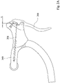
- Fig. 2A shows one side view of the adjustment structure 100A of the hydraulic brake system of Fig. 1 after a length of the brake cable 201 is changed by adjusting the brake lever 200.
- Fig. 2B shows a cross-sectional view of the adjustment structure 100A of the hydraulic brake system of Fig. 1 after an adjusting device 130A being operated.
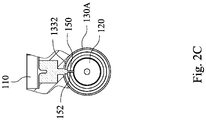
- Fig. 2C shows a partial cross-sectional view of the adjustment structure 100A of the hydraulic brake system of Fig. 2B taken along line 4c-4c.
- the adjustment structure 100A of the hydraulic brake system is coordinated with a brake cable 201 controlled by a brake lever 200.
- the adjustment structure 100A of the hydraulic brake system is detachably assembled on a handlebar 300.
- the adjustment structure 100A of the hydraulic brake system includes a main body 110, a piston 120, an adjusting device 130A, a returning spring 140 and a sleeve tube 150.
- the main body 110 includes a fluid reservoir 111, an inner chamber 112 and at least one fluid passage (not labeled).
- the inner chamber 112 includes a cylinder channel 1121 and an opening part 1122 communicated with the cylinder channel 1121, and the fluid passage is filled with a hydraulic fluid.
- the cylinder channel 1121 is communicated with the fluid reservoir 111 through a fluid port 114 of the fluid passage, and the hydraulic fluid can flow out of the cylinder channel 1121 via a hydraulic hose 115.
- the adjusting device 130A includes a tube body.
- the adjusting device 130A is disposed in the inner chamber 112, and a first end 1301 of the adjusting device 130A is rotatably located in the cylinder channel 1121.
- the adjusting device 130A includes an annular fluid guiding passage 133 located at the first end 1301 of the adjusting device 130A and is corresponding to the fluid port 114.
- a second end 1302 of the adjusting device 130A is exposed from the opening part 1122 for manually operating.
- the adjusting device 130A includes an inner thread 134.
- the annular fluid guiding passage 133 of the adjusting device 130A includes an annular groove 1331 and a guiding port 1332.
- the annular groove 1331 rotatably surrounds an outside of the adjusting device 130A and is communicated with the fluid port 114.
- the guiding port 1332 is communicated with the annular groove 1331 and a plurality of supplying ports 152 which will be described in the following paragraphs.
- the returning spring 140 is abutted between the inner chamber 112 and the piston 120.
- the sleeve tube 150 is securely positioned in the main body 110, and is disposed in the first end 1301 of the adjusting device 130A.
- the sleeve tube 150 includes an outer thread 151 coupled to the inner thread 134 of the adjusting device 130A, and the adjusting device 130A is moved relative to the sleeve tube 150 reciprocatedly when rotating.
- the sleeve tube 150 includes the supplying ports 152 arranged along the axis of the sleeve tube 150.
- An inner space of the sleeve tube 150 is communicated with the fluid reservoir 111 through at least one of the supplying ports 152, the annular fluid guiding passage 133 and the fluid port 114.
- the piston 120 includes a seal 121.
- the piston 120 is located within the sleeve tube 150 which is located in the cylinder channel 1121.
- the piston 120 includes a cable hole 1201 for receiving the brake cable 201.
- the piston 120 having a plurality of operated positions relative to the supplying ports 152. When the piston 120 is located at any one of the normal operated positions, the hydraulic brake system can be operated normally, and the piston 120 will not exceed or block all the supplying ports 152.
- a user can simply rotate the second end 1302 of the adjusting device 130A to operate the adjustment structure 100A of the hydraulic brake system.
- the piston 120 connected with the brake cable 201 will leave the original operated position to move toward the brake lever 200, as shown in Figs. 2B and 2C , and the piston 120 may exceed or block the outermost supplying port 152 which is communicated with the fluid port 114 through the annular fluid guiding passage 133. In such a situation, the brake may be locked and unable to work.
- the user can rotate the adjusting device 130A manually such that the adjusting device 130A can be moved relative to the sleeve tube 150 to allow the innermost supplying port 152 to communicate with the fluid reservoir 111 through the annular fluid guiding passage 133 and the fluid port 114, and the piston 120 is located at the normal operated position relative to the innermost supplying port 152.
- the piston 120 is moved owing to the brake cable 201 adjusted with the maximum adjustable distance A, through the movement of the adjusting device 130A, at least one supplying port 152 will be communicated with the fluid reservoir 111 such that the piston 120 will be located at one of the normal operated positions relative to the supplying port 152 and will not exceed or block all the supplying ports 152; thus, the hydraulic brake system can work normally.
- the piston 120 can be located at one of the normal operated position by simply and manually operating the adjusting device 130A.
- the adjustment structure 100A of the hydraulic brake system can prevent the situation that the piston 120 and the seal 121 exceed or block the supplying ports 152.
- the tube body of the adjusting device 130A is sleeved on an outside of the sleeve tube 150 without abutting the piston 120, the tube body of the adjusting device 130A is sleeved on an outside of the piston 120 such that the volume can become more compacted and the structure can be simplified.
- the adjustment structure 100A of the hydraulic brake system includes a positioning device 400.
- the positioning device 400 is disposed at the main body 110, and the positioning device 400 includes an abutted ball 401 abutted against the adjusting device 130A.
- the adjusting device 130A includes a plurality of positioning grooves 135 coordinated with the abutted ball 401.
- a visible mark (not labeled) can be located at an outer surface of the second end 1302 of the adjusting device 130A, which is exposed from the opening part 1122. The visible mark shows an adjusting length or a rotatable angle of the adjusting device 130A.
- Fig. 3A shows a cross-sectional view of an adjustment structure 100B of a hydraulic brake system according to a second embodiment of the present invention.
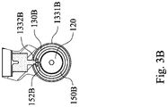
- Fig. 3B shows a partial cross-sectional view of the adjustment structure 100B of the hydraulic brake system of Fig. 3A taken along line 5b-5b.
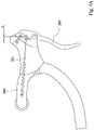
- Fig. 4A shows one side view of the adjustment structure 100B of the hydraulic brake system of Fig. 3A after a length of the brake cable 201 is changed by adjusting the brake lever 200.
- Fig. 4B-1 shows one cross-sectional view of the adjustment structure 100B of the hydraulic brake system of Fig.
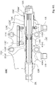
- Fig. 4B-2 shows another cross-sectional view of the adjustment structure 100B of the hydraulic brake system of Fig. 3A after the adjusting device 130B being operated.
- Fig. 4C-1 shows a partial cross-sectional view of the adjustment structure 100B of the hydraulic brake system of Fig. 4B-1 taken along line 6c-1-6c-1.
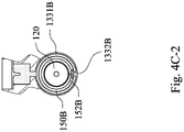
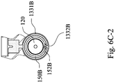
- Fig. 4C-2 shows a partial cross-sectional view of the adjustment structure 100B of the hydraulic brake system of Fig. 4B-2 taken along line 6c-2-6c-2.
- the adjustment structure 100B of the hydraulic brake system is coordinated with a brake cable 201 controlled by a brake lever 200.
- the adjustment structure 100B of the hydraulic brake system is detachably assembled on a handlebar 300.
- the adjustment structure 100B of the hydraulic brake system includes a main body 110, a piston 120, an adjusting device 130B, a returning spring 140 and a sleeve tube 150B.
- the main body 110 includes a fluid reservoir 111, an inner chamber 112 and at least one fluid passage (not labeled).
- the inner chamber 112 includes a cylinder channel 1121 and an opening part 1122 communicated with the cylinder channel 1121, and the fluid passage is filled with a hydraulic fluid.
- the cylinder channel 1121 is communicated with the fluid reservoir 111 by a fluid port 114 of the fluid passage, and the hydraulic fluid can flow out of the cylinder channel 1121 via a hydraulic hose 115.
- the adjusting device 130B includes a tube body.
- the adjusting device 130B is disposed in the inner chamber 112, and a first end 1301B of the adjusting device 130B is rotatably located in the cylinder channel 1121.
- the adjusting device 130B includes an annular fluid guiding passage 133B located at the first end 1301B of the adjusting device 130B and is corresponding to the fluid port 114.
- a second end 1302B of the adjusting device 130B is exposed from the opening part 1122 for manually operating.
- the annular fluid guiding passage 133B of the adjusting device 130B includes an annular groove 1331B and a plurality of guiding ports 1332B arranged along a spiral path.
- the annular groove 1331B rotatably surrounds an outside of the adjusting device 130B and is communicated with the fluid port 114.
- Different guiding ports 1332B are communicated with the annular groove 1331B and different supplying ports 152B which will be described in the following paragraphs.
- the returning spring 140 is abutted between the inner chamber 112 and the piston 120.
- the sleeve tube 150B is positioned in the main body 110, and is disposed in the first end 1301B of the adjusting device 130B.
- the adjusting device 130B is disposed at an outside of the sleeve tube 150B and can be rotated liquid-tightly.
- the sleeve tube 150B includes a plurality of supplying ports 152B arranged along a spiral path, and the fluid reservoir 111 is communicated with at least one of the supplying ports 152B through the fluid port 114 and the annular fluid guiding passage 133B.
- Each of the guiding ports 1332B of the adjusting device 130B is communicated with one of the supplying ports 152B when the adjusting device 130B is rotated to align with one of the supplying ports 152B at a corresponding rotating degree of the adjusting device 130B.
- the piston 120 includes a seal (not labeled).
- the piston 120 is located within the sleeve tube 150B which is located in the cylinder channel 1121.
- the piston 120 includes a cable hole 1201 for receiving the brake cable 201.
- the piston 120 has a plurality of operated positions relative to the plurality of supplying ports 152B. When the piston 120 is located at any one of the normal operated positions, the hydraulic brake system can be operated normally, and the piston 120 will not exceed or block all the supplying ports 152B.
- the piston 120 shown in each of Figs. 3A and 3B is located in the normal operated position, and the hydraulic brake system can work normally.
- the piston 120 is located at the normal operated position relative to the outermost supplying port 152B while the outermost guiding port 1332B is communicated with the fluid reservoir 111 through the outermost supplying port 152B, the annular fluid guiding passage 133B and the fluid port 114.
- the piston 120 connected with the brake cable 201 will leave the original operated position to move toward the brake lever 200, as shown in Figs. 4B-1 and 4B-2 .
- the piston 120 may exceed the original operated position relative to the outermost supplying port 152B; meanwhile, the piston 120 may be moved to the normal operated position relative to the middle or the innermost supplying port 152B.
- the user can rotate the second end 1302B of the adjusting device 130B to adjust the guiding ports 1332B to be rotated to different rotating degrees, e.g., 90 degrees in Fig. 4C-1 or 180 degrees in Fig. 4C-2 .
- One of the guiding ports 1332B is communicated with the annular groove 1331B and the appropriate supplying port 152B, e.g., the middle or the innermost supplying port 152B, such that the piston 120 can be operated normally.
- a visible mark (not labeled) can be located at an outer surface of the second end 1302B of the adjusting device 130B, which is exposed from the opening part 1122. The visible mark shows an adjusting length or a rotatable angle of the adjusting device 130B.
- Fig. 5 shows a cross-sectional view of an adjustment structure 100C of a hydraulic brake system according to a third embodiment of the present invention.
- Fig. 6A shows one cross-sectional view of the adjustment structure 100C of the hydraulic brake system of Fig. 5 before an adjusting device 130C being operated.
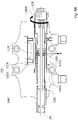
- Fig. 6B shows another cross-sectional view of the adjustment structure 100C of the hydraulic brake system of Fig. 5 after the adjusting device 130C being operated.
- only one inner chamber 112 is shown in Figs. 6A and 6B .
- the adjustment structure 100C of the hydraulic brake system is coordinated with a brake cable 201 controlled by a brake lever.
- the adjustment structure 100C of the hydraulic brake system is detachably assembled on a handlebar.
- the adjustment structure 100C of the hydraulic brake system includes a main body 110C, a piston 120C, an adjusting device 130C and a returning spring 140C.
- the main body 110C includes a fluid reservoir 111C, an inner chamber 112C and at least one fluid passage (not labeled).
- the inner chamber 112C includes a cylinder channel 1121C and an opening part 1122C communicated with the cylinder channel 1121C, and the fluid passage is filled with a hydraulic fluid.
- the cylinder channel 1121C is communicated with the fluid reservoir 111C through a fluid port 114C of the fluid passage, and the hydraulic fluid can flow out of the cylinder channel 1121C via a hydraulic hose 115.
- the main body 110C includes an inner thread 1123C disposed at an inner wall of the opening part 1122C.
- the adjusting device 130C includes a tube body and an outer thread 134C located at an outer wall of tube body.
- the outer thread 134C of the adjusting device 130C is coupled to the inner thread 1123C located within opening part 1122C of the main body 110C.
- a second end 1302C of the adjusting device 130C is exposed from the opening part 1122C for manually operating, and a first end 1301C is rotated to move reciprocatedly within the cylinder channel 1121C.
- the adjusting device 130C includes an annular fluid guiding passage 133C.
- the annular fluid guiding passage 133C includes an annular groove 1331C and a guiding port 1332C communicated with the annular groove 1331C.
- the annular groove 1331C rotatably surrounds an outside of the adjusting device 130C and is communicated with the fluid port 114C.
- the cylinder channel 1121C is communicated with the fluid reservoir 111C through the guiding port 1332C.
- the piston 120C is connected with the brake cable 201 and disposed within the adjusting device 130C liquid-tightly.
- the piston 120C includes a positioning ring 122C disposed at one end of the piston 120C to allow the piston 120C to be remained at the normal operated position in the cylinder channel 1121C.
- the piston 120C includes a cable hole 1201 for receiving the brake cable 201.
- the piston 120C connected with the brake cable 201 can be moved within the adjusting device 130C.
- the guiding port 1332C is moved by operating the adjusting device 130C to change the relative position between the piston 120C and the guiding port 1332C such that the piston 120C can be located at the normal operated position B again.
- the piston 120C includes a visible mark 123C located at an outer surface of a cable securing element (not labeled) of the adjusting device 130C, which is exposed from the opening part 1122C.
- the visible mark 123C shows an adjusting length of the adjusting device 130C relative to the second end 1302C of the adjusting device 130C.
- the returning spring 140C is abutted between the inner chamber 112C and the piston 120C, and the returning spring 140C pushes the piston 120C to be abutted against the cable securing element of the adjusting device 130C.
- the adjustment structure 100C of the hydraulic brake system can further include a positioning device 400.
- the positioning device 400 is disposed at the main body 110C, and the positioning device 400 includes an abutted ball 401 abutted against the adjusting device 130C.
- the adjusting device 130C includes a plurality of positioning grooves 135C coordinated with the abutted ball 401. When rotating the adjusting device 130C, the abutted ball 401 will be located at different positioning grooves 135C according to the movement of the adjusting device 130C to achieve the effect of segmental positioning.
- the hydraulic brake system cannot work properly.
- the piston 120C is relocated at the normal operated position B through the movement and the fluid communicating relationship of the guiding port 1332C.
- the piston 120C can be relocated at the normal operated position B, and the piston 120C will not exceed or block the guiding port 1332C.
- each of the embodiments of the present invention can have two inner chambers (as shown in Fig. 5 ) and two fluid passages which represent the fluid ports, the guiding ports, the supplying ports, the annular fluid guiding passage or the communicating route therebetween which allows the hydraulic fluid to pass therethrough.
- the hydraulic fluid can be provided to the two inner chambers.
- the abovementioned mechanism is only one of the embodiments which can be carried out, and the present invention is not limited thereto.
- the normal operated position mentioned in the present invention does not represent a specific position, and the normal operated position is a position of the piston relative to the fluid port, the guiding port or the supplying port.
- the abovementioned brake lever can be a main brake lever or a sub-brake lever with small size.
- the adjusting device when the adjusting device is rotatable and has one end exposed from the opening part, or a visible mark (not labeled) can be located at the outer surface of the adjusting device or the element exposed from the opening part, e.g., the cable securing element, the user can know the rotating angle or the adjusting length of the adjusting device through visible identification.
- a visible mark not labeled
- the present invention has the following advantages: 1.
- the adjusting device can be manually operated to move the piston, the supplying ports or the guiding port to adjust the piston to be located at the normal operated position; 2.
- the adjusting device is disposed at the opening part, and the piston includes a cable hole for receiving the brake cable, the volume can be effectively compacted and the structure can be simplified to solve the assembly difficulty, and the demands of small sized bike components can be satisfied; 3.
- the positioning device can assist the adjusting device to be accurately adjusted; and 4.
- the visible mark located at the outer surface of the adjusting device or the element exposed from the opening part, e.g., the cable securing element, can illustrate the rotating angle or the movement of the adjusting device.
Landscapes
- Engineering & Computer Science (AREA)
- Mechanical Engineering (AREA)
- Physics & Mathematics (AREA)
- Fluid Mechanics (AREA)
- General Engineering & Computer Science (AREA)
- Transportation (AREA)
- Transmission Of Braking Force In Braking Systems (AREA)
- Braking Arrangements (AREA)
Claims (4)
- Anpassungsstruktur (100C), die in einem hydraulischen Bremssystem verwendet wird und mit einem durch einen Bremshebel (200) gesteuerten Bremskabel (201) koordiniert ist, wobei die Anpassungsstruktur (100C) umfasst:einen Hauptkörper (1 10C), umfassend ein Fluidreservoir (111C), eine innere Kammer (112C) und wenigstens einen Fluidanschluss (114C), wobei die innere Kammer (112C) einen Zylinderkanal (1121C) und einen Öffnungsteil (1122C) umfasst, der mit dem Zylinderkanal (1121C) kommuniziert;eine Anpassvorrichtung (130C), die in den Öffnungsteil (1122C) des Hauptkörpers (110C) geschraubt ist, wobei die Anpassvorrichtung (130C) gedreht wird, um sich in dem Zylinderkanal (1121C) hin- und herzubewegen, und die Anpassvorrichtung (130C) einen ringförmigen Fluidführungsdurchgang (133C) umfasst, wobei der ringförmige Fluidführungsdurchgang (133C) umfasst:einen Führungsanschluss (1332C); undeine ringförmige Nut (1331C), die mit dem Führungsanschluss (1332C) verbunden ist, wobei die ringförmige Nut (1331C) eine Außenseite der Anpassvorrichtung (130C) umgibt und mit dem Zylinderkanal (1121C) und dem Fluidreservoir (111C) über den wenigstens einen Fluidanschluss (114C) verbunden ist;einen Kolben (120C), der mit dem Bremskabel (201) verbunden und flüssigkeitsdicht in der Anpassvorrichtung (130C) angeordnet ist, wobei der Kolben (120C) in dem Zylinderkanal (1121C) begrenzt bewegt wird und ein Kabelloch (1201) für die Aufnahme des Bremskabels (201) umfasst, und die Anpassvorrichtung (130C) gedreht wird, um den Kolben (120C) anzupassen, um sich in einer normalen betriebenen Position (B) relativ zu dem Fluidanschluss (1332C) zu befinden;eine Rückstellfeder (140C), die zwischen dem Hauptkörper (110C) und dem Kolben (120C) angegrenzt ist; gekennzeichnet durcheine an dem Hauptkörper (110C) angeordnete Positioniervorrichtung (400), wobei die Positioniervorrichtung (400) eine an der Anpassvorrichtung (130C) angrenzende Kugel (401) umfasst;wobei die Anpassvorrichtung (130C) eine Positionierungsnut (135C) umfasst, die mit der angrenzenden Kugel (401) koordiniert ist.
- Anpassungsstruktur (100C) nach Anspruch 1, wobei der Kolben (120C) umfasst:eine sichtbare Markierung (123C), die sich an einer äußeren Oberfläche eines Kabelsicherungselements (1322) der Anpassvorrichtung (130C) befindet, die von dem Öffnungsteil (1122C) aus sichtbar ist;wobei die sichtbare Markierung (123C) eine Anpasslänge der Anpassvorrichtung (130C) anzeigt.
- Anpassungsstruktur (100C) nach Anspruch 1, wobei die Anpassungsstruktur (100C) des hydraulischen Bremssystems abnehmbar an einer Lenkstange (300) montiert ist, eine Anzahl der inneren Kammern (112C) zwei ist und jede der inneren Kammern (112C) mit dem Fluidreservoir (111C) kommuniziert.
- Anpassungsstruktur (100C) nach Anspruch 1, wobei der Kolben (120C) umfasst:
einen Positionierungsring (122C), der in dem Zylinderkanal (1121C) angeordnet ist, wobei der Positionierungsring (122C) mit der Rückstellfeder (140C) koordiniert ist, um zu ermöglichen, dass der Kolben (120C), der mit dem Bremskabel (201) verbunden ist, in der normalen betriebenen Position (B) verbleibt.
Applications Claiming Priority (1)
| Application Number | Priority Date | Filing Date | Title |
|---|---|---|---|
| TW106128634A TWI660877B (zh) | 2017-08-23 | 2017-08-23 | 外掛式煞車調整機構 |
Publications (2)
| Publication Number | Publication Date |
|---|---|
| EP3456595A1 EP3456595A1 (de) | 2019-03-20 |
| EP3456595B1 true EP3456595B1 (de) | 2023-01-04 |
Family
ID=63363984
Family Applications (1)
| Application Number | Title | Priority Date | Filing Date |
|---|---|---|---|
| EP18190258.6A Active EP3456595B1 (de) | 2017-08-23 | 2018-08-22 | Nachstelleinrichtung für ein hydraulisches bremssystem |
Country Status (6)
| Country | Link |
|---|---|
| US (1) | US11067143B2 (de) |
| EP (1) | EP3456595B1 (de) |
| JP (1) | JP6746638B2 (de) |
| CN (1) | CN109421875B (de) |
| AU (1) | AU2018220013B2 (de) |
| TW (1) | TWI660877B (de) |
Family Cites Families (12)
| Publication number | Priority date | Publication date | Assignee | Title |
|---|---|---|---|---|
| FR2681116B1 (fr) * | 1991-09-10 | 1995-09-15 | Gabillon Jean | Dispositif de commande d'un frein a disque pour vehicule. |
| DE29601448U1 (de) * | 1996-01-29 | 1996-04-04 | Klein, Thomas, 63110 Rodgau | Hydraulischer Bowdenzug zum Gangwechsel und zur Bremsbetätigung an Fahrrädern |
| US6341673B1 (en) * | 2000-04-07 | 2002-01-29 | Kuo Yung-Pin | Actuator for a hydraulic brake system of bicycles |
| CN2474422Y (zh) * | 2001-02-27 | 2002-01-30 | 李木凯 | 碟式刹车器的刹车片调整装置 |
| CN2928666Y (zh) * | 2006-07-19 | 2007-08-01 | 亨通机械股份有限公司 | 把手的刹车调整器 |
| JP2011159111A (ja) * | 2010-02-01 | 2011-08-18 | Shimano Inc | 自転車用ブレーキ及び変速操作装置 |
| US9334012B1 (en) * | 2013-09-13 | 2016-05-10 | Gregory Alan Ward | Brake safety apparatus |
| TWI552905B (zh) * | 2014-04-21 | 2016-10-11 | Tektro Technology Corp | Hydraulic brake master cylinder |
| US9371110B2 (en) * | 2014-04-30 | 2016-06-21 | Tektro Technology Corporation | Hydraulic brake master cylinder |
| TWI589483B (zh) * | 2014-11-20 | 2017-07-01 | Tektro Tech Corp | Medium-pull semi-hydraulic brake caliper structure |
| US9464677B2 (en) * | 2015-02-28 | 2016-10-11 | Tektro Technology Corp | Center-pull hydraulic brake caliper structure for a bicycle |
| TWM522177U (zh) * | 2015-11-13 | 2016-05-21 | 巨大機械工業股份有限公司 | 自行車之油壓碟煞裝置 |
-
2017
- 2017-08-23 TW TW106128634A patent/TWI660877B/zh active
-
2018
- 2018-07-31 JP JP2018144190A patent/JP6746638B2/ja active Active
- 2018-08-21 AU AU2018220013A patent/AU2018220013B2/en active Active
- 2018-08-21 CN CN201810953824.9A patent/CN109421875B/zh active Active
- 2018-08-21 US US16/108,063 patent/US11067143B2/en active Active
- 2018-08-22 EP EP18190258.6A patent/EP3456595B1/de active Active
Also Published As
| Publication number | Publication date |
|---|---|
| US20190063531A1 (en) | 2019-02-28 |
| TWI660877B (zh) | 2019-06-01 |
| JP6746638B2 (ja) | 2020-08-26 |
| US11067143B2 (en) | 2021-07-20 |
| AU2018220013B2 (en) | 2020-04-02 |
| AU2018220013A1 (en) | 2019-03-14 |
| CN109421875A (zh) | 2019-03-05 |
| EP3456595A1 (de) | 2019-03-20 |
| CN109421875B (zh) | 2020-10-30 |
| TW201912492A (zh) | 2019-04-01 |
| JP2019038528A (ja) | 2019-03-14 |
Similar Documents
| Publication | Publication Date | Title |
|---|---|---|
| EP1693244B1 (de) | Hydraulische Scheibenbremshebeleinheit | |
| CN107521606B (zh) | 制动控制装置 | |
| US7540147B2 (en) | Master cylinder lever for a hydraulic brake with dead-band adjustment mechanism | |
| US4152897A (en) | Tandem brake master cylinder | |
| JP2010502463A (ja) | 工具ホルダのロックロッド用引き戻し力増幅装置 | |
| US3972191A (en) | Balanced servomotor valve | |
| EP1870328B1 (de) | Hebelanordnung für eine hydraulische Scheibenbremse | |
| US6729132B2 (en) | Remotely and directly pedal operated hydraulic compact booster for bi-directional braking | |
| US11492068B2 (en) | Control device of a hydraulic brake, braking member and hydraulic braking system for a bicycle and method for storing and transporting a hydraulic braking system for a bicycle | |
| AU2018220013B2 (en) | Adjustment structure of hydraulic brake system | |
| JP2008222214A (ja) | 差動液圧マスターシリンダ | |
| JPS625821B2 (de) | ||
| EP0554727B1 (de) | Kolbenstangenlose Zylindereinheit mit Bremse | |
| JP2005075258A (ja) | ブレーキマスタシリンダ及びその製造方法 | |
| JPS6213227B2 (de) | ||
| US7197875B2 (en) | Hydraulic cylinder with coaxial, in-line reservoir | |
| US4033131A (en) | Two stage servomotor | |
| US3990241A (en) | Valve locking means for a two stage servomotor | |
| US10053182B2 (en) | Hydraulic pressure master cylinder for bar-handle vehicle | |
| US9963201B2 (en) | Bicycle hydraulic component | |
| EP0327357B1 (de) | Hauptzylinder | |
| US2852919A (en) | Brake wear compensating device | |
| JP6530231B2 (ja) | バーハンドル車両用液圧マスタシリンダ装置 | |
| JPH11157435A (ja) | パッド部の摩耗を自動補償するブレーキマスター シリンダー | |
| JPH11198794A (ja) | マスタシリンダ |
Legal Events
| Date | Code | Title | Description |
|---|---|---|---|
| PUAI | Public reference made under article 153(3) epc to a published international application that has entered the european phase |
Free format text: ORIGINAL CODE: 0009012 |
|
| STAA | Information on the status of an ep patent application or granted ep patent |
Free format text: STATUS: REQUEST FOR EXAMINATION WAS MADE |
|
| 17P | Request for examination filed |
Effective date: 20180822 |
|
| AK | Designated contracting states |
Kind code of ref document: A1 Designated state(s): AL AT BE BG CH CY CZ DE DK EE ES FI FR GB GR HR HU IE IS IT LI LT LU LV MC MK MT NL NO PL PT RO RS SE SI SK SM TR |
|
| AX | Request for extension of the european patent |
Extension state: BA ME |
|
| RIC1 | Information provided on ipc code assigned before grant |
Ipc: B62L 3/02 20060101ALI20220608BHEP Ipc: B60T 11/236 20060101AFI20220608BHEP |
|
| GRAP | Despatch of communication of intention to grant a patent |
Free format text: ORIGINAL CODE: EPIDOSNIGR1 |
|
| STAA | Information on the status of an ep patent application or granted ep patent |
Free format text: STATUS: GRANT OF PATENT IS INTENDED |
|
| INTG | Intention to grant announced |
Effective date: 20220727 |
|
| GRAS | Grant fee paid |
Free format text: ORIGINAL CODE: EPIDOSNIGR3 |
|
| GRAA | (expected) grant |
Free format text: ORIGINAL CODE: 0009210 |
|
| STAA | Information on the status of an ep patent application or granted ep patent |
Free format text: STATUS: THE PATENT HAS BEEN GRANTED |
|
| AK | Designated contracting states |
Kind code of ref document: B1 Designated state(s): AL AT BE BG CH CY CZ DE DK EE ES FI FR GB GR HR HU IE IS IT LI LT LU LV MC MK MT NL NO PL PT RO RS SE SI SK SM TR |
|
| REG | Reference to a national code |
Ref country code: GB Ref legal event code: FG4D |
|
| REG | Reference to a national code |
Ref country code: DE Ref legal event code: R096 Ref document number: 602018044942 Country of ref document: DE |
|
| REG | Reference to a national code |
Ref country code: CH Ref legal event code: EP |
|
| REG | Reference to a national code |
Ref country code: AT Ref legal event code: REF Ref document number: 1541739 Country of ref document: AT Kind code of ref document: T Effective date: 20230115 |
|
| REG | Reference to a national code |
Ref country code: IE Ref legal event code: FG4D |
|
| REG | Reference to a national code |
Ref country code: NL Ref legal event code: FP |
|
| REG | Reference to a national code |
Ref country code: LT Ref legal event code: MG9D |
|
| REG | Reference to a national code |
Ref country code: AT Ref legal event code: MK05 Ref document number: 1541739 Country of ref document: AT Kind code of ref document: T Effective date: 20230104 |
|
| PG25 | Lapsed in a contracting state [announced via postgrant information from national office to epo] |
Ref country code: RS Free format text: LAPSE BECAUSE OF FAILURE TO SUBMIT A TRANSLATION OF THE DESCRIPTION OR TO PAY THE FEE WITHIN THE PRESCRIBED TIME-LIMIT Effective date: 20230104 Ref country code: PT Free format text: LAPSE BECAUSE OF FAILURE TO SUBMIT A TRANSLATION OF THE DESCRIPTION OR TO PAY THE FEE WITHIN THE PRESCRIBED TIME-LIMIT Effective date: 20230504 Ref country code: NO Free format text: LAPSE BECAUSE OF FAILURE TO SUBMIT A TRANSLATION OF THE DESCRIPTION OR TO PAY THE FEE WITHIN THE PRESCRIBED TIME-LIMIT Effective date: 20230404 Ref country code: LV Free format text: LAPSE BECAUSE OF FAILURE TO SUBMIT A TRANSLATION OF THE DESCRIPTION OR TO PAY THE FEE WITHIN THE PRESCRIBED TIME-LIMIT Effective date: 20230104 Ref country code: LT Free format text: LAPSE BECAUSE OF FAILURE TO SUBMIT A TRANSLATION OF THE DESCRIPTION OR TO PAY THE FEE WITHIN THE PRESCRIBED TIME-LIMIT Effective date: 20230104 Ref country code: HR Free format text: LAPSE BECAUSE OF FAILURE TO SUBMIT A TRANSLATION OF THE DESCRIPTION OR TO PAY THE FEE WITHIN THE PRESCRIBED TIME-LIMIT Effective date: 20230104 Ref country code: ES Free format text: LAPSE BECAUSE OF FAILURE TO SUBMIT A TRANSLATION OF THE DESCRIPTION OR TO PAY THE FEE WITHIN THE PRESCRIBED TIME-LIMIT Effective date: 20230104 Ref country code: AT Free format text: LAPSE BECAUSE OF FAILURE TO SUBMIT A TRANSLATION OF THE DESCRIPTION OR TO PAY THE FEE WITHIN THE PRESCRIBED TIME-LIMIT Effective date: 20230104 |
|
| PG25 | Lapsed in a contracting state [announced via postgrant information from national office to epo] |
Ref country code: SE Free format text: LAPSE BECAUSE OF FAILURE TO SUBMIT A TRANSLATION OF THE DESCRIPTION OR TO PAY THE FEE WITHIN THE PRESCRIBED TIME-LIMIT Effective date: 20230104 Ref country code: PL Free format text: LAPSE BECAUSE OF FAILURE TO SUBMIT A TRANSLATION OF THE DESCRIPTION OR TO PAY THE FEE WITHIN THE PRESCRIBED TIME-LIMIT Effective date: 20230104 Ref country code: IS Free format text: LAPSE BECAUSE OF FAILURE TO SUBMIT A TRANSLATION OF THE DESCRIPTION OR TO PAY THE FEE WITHIN THE PRESCRIBED TIME-LIMIT Effective date: 20230504 Ref country code: GR Free format text: LAPSE BECAUSE OF FAILURE TO SUBMIT A TRANSLATION OF THE DESCRIPTION OR TO PAY THE FEE WITHIN THE PRESCRIBED TIME-LIMIT Effective date: 20230405 Ref country code: FI Free format text: LAPSE BECAUSE OF FAILURE TO SUBMIT A TRANSLATION OF THE DESCRIPTION OR TO PAY THE FEE WITHIN THE PRESCRIBED TIME-LIMIT Effective date: 20230104 |
|
| REG | Reference to a national code |
Ref country code: DE Ref legal event code: R097 Ref document number: 602018044942 Country of ref document: DE |
|
| PG25 | Lapsed in a contracting state [announced via postgrant information from national office to epo] |
Ref country code: SM Free format text: LAPSE BECAUSE OF FAILURE TO SUBMIT A TRANSLATION OF THE DESCRIPTION OR TO PAY THE FEE WITHIN THE PRESCRIBED TIME-LIMIT Effective date: 20230104 Ref country code: RO Free format text: LAPSE BECAUSE OF FAILURE TO SUBMIT A TRANSLATION OF THE DESCRIPTION OR TO PAY THE FEE WITHIN THE PRESCRIBED TIME-LIMIT Effective date: 20230104 Ref country code: EE Free format text: LAPSE BECAUSE OF FAILURE TO SUBMIT A TRANSLATION OF THE DESCRIPTION OR TO PAY THE FEE WITHIN THE PRESCRIBED TIME-LIMIT Effective date: 20230104 Ref country code: DK Free format text: LAPSE BECAUSE OF FAILURE TO SUBMIT A TRANSLATION OF THE DESCRIPTION OR TO PAY THE FEE WITHIN THE PRESCRIBED TIME-LIMIT Effective date: 20230104 Ref country code: CZ Free format text: LAPSE BECAUSE OF FAILURE TO SUBMIT A TRANSLATION OF THE DESCRIPTION OR TO PAY THE FEE WITHIN THE PRESCRIBED TIME-LIMIT Effective date: 20230104 |
|
| PLBE | No opposition filed within time limit |
Free format text: ORIGINAL CODE: 0009261 |
|
| STAA | Information on the status of an ep patent application or granted ep patent |
Free format text: STATUS: NO OPPOSITION FILED WITHIN TIME LIMIT |
|
| PG25 | Lapsed in a contracting state [announced via postgrant information from national office to epo] |
Ref country code: SK Free format text: LAPSE BECAUSE OF FAILURE TO SUBMIT A TRANSLATION OF THE DESCRIPTION OR TO PAY THE FEE WITHIN THE PRESCRIBED TIME-LIMIT Effective date: 20230104 |
|
| 26N | No opposition filed |
Effective date: 20231005 |
|
| PG25 | Lapsed in a contracting state [announced via postgrant information from national office to epo] |
Ref country code: SI Free format text: LAPSE BECAUSE OF FAILURE TO SUBMIT A TRANSLATION OF THE DESCRIPTION OR TO PAY THE FEE WITHIN THE PRESCRIBED TIME-LIMIT Effective date: 20230104 |
|
| PG25 | Lapsed in a contracting state [announced via postgrant information from national office to epo] |
Ref country code: MC Free format text: LAPSE BECAUSE OF FAILURE TO SUBMIT A TRANSLATION OF THE DESCRIPTION OR TO PAY THE FEE WITHIN THE PRESCRIBED TIME-LIMIT Effective date: 20230104 |
|
| REG | Reference to a national code |
Ref country code: CH Ref legal event code: PL |
|
| PG25 | Lapsed in a contracting state [announced via postgrant information from national office to epo] |
Ref country code: MC Free format text: LAPSE BECAUSE OF FAILURE TO SUBMIT A TRANSLATION OF THE DESCRIPTION OR TO PAY THE FEE WITHIN THE PRESCRIBED TIME-LIMIT Effective date: 20230104 |
|
| PG25 | Lapsed in a contracting state [announced via postgrant information from national office to epo] |
Ref country code: LU Free format text: LAPSE BECAUSE OF NON-PAYMENT OF DUE FEES Effective date: 20230822 |
|
| PG25 | Lapsed in a contracting state [announced via postgrant information from national office to epo] |
Ref country code: LU Free format text: LAPSE BECAUSE OF NON-PAYMENT OF DUE FEES Effective date: 20230822 Ref country code: CH Free format text: LAPSE BECAUSE OF NON-PAYMENT OF DUE FEES Effective date: 20230831 |
|
| REG | Reference to a national code |
Ref country code: BE Ref legal event code: MM Effective date: 20230831 |
|
| REG | Reference to a national code |
Ref country code: IE Ref legal event code: MM4A |
|
| PG25 | Lapsed in a contracting state [announced via postgrant information from national office to epo] |
Ref country code: IT Free format text: LAPSE BECAUSE OF FAILURE TO SUBMIT A TRANSLATION OF THE DESCRIPTION OR TO PAY THE FEE WITHIN THE PRESCRIBED TIME-LIMIT Effective date: 20230104 |
|
| PG25 | Lapsed in a contracting state [announced via postgrant information from national office to epo] |
Ref country code: IE Free format text: LAPSE BECAUSE OF NON-PAYMENT OF DUE FEES Effective date: 20230822 |
|
| PG25 | Lapsed in a contracting state [announced via postgrant information from national office to epo] |
Ref country code: IE Free format text: LAPSE BECAUSE OF NON-PAYMENT OF DUE FEES Effective date: 20230822 |
|
| PG25 | Lapsed in a contracting state [announced via postgrant information from national office to epo] |
Ref country code: BE Free format text: LAPSE BECAUSE OF NON-PAYMENT OF DUE FEES Effective date: 20230831 |
|
| PG25 | Lapsed in a contracting state [announced via postgrant information from national office to epo] |
Ref country code: BG Free format text: LAPSE BECAUSE OF FAILURE TO SUBMIT A TRANSLATION OF THE DESCRIPTION OR TO PAY THE FEE WITHIN THE PRESCRIBED TIME-LIMIT Effective date: 20230104 |
|
| PG25 | Lapsed in a contracting state [announced via postgrant information from national office to epo] |
Ref country code: BG Free format text: LAPSE BECAUSE OF FAILURE TO SUBMIT A TRANSLATION OF THE DESCRIPTION OR TO PAY THE FEE WITHIN THE PRESCRIBED TIME-LIMIT Effective date: 20230104 |
|
| PG25 | Lapsed in a contracting state [announced via postgrant information from national office to epo] |
Ref country code: CY Free format text: LAPSE BECAUSE OF FAILURE TO SUBMIT A TRANSLATION OF THE DESCRIPTION OR TO PAY THE FEE WITHIN THE PRESCRIBED TIME-LIMIT; INVALID AB INITIO Effective date: 20180822 |
|
| PG25 | Lapsed in a contracting state [announced via postgrant information from national office to epo] |
Ref country code: HU Free format text: LAPSE BECAUSE OF FAILURE TO SUBMIT A TRANSLATION OF THE DESCRIPTION OR TO PAY THE FEE WITHIN THE PRESCRIBED TIME-LIMIT; INVALID AB INITIO Effective date: 20180822 |
|
| PGFP | Annual fee paid to national office [announced via postgrant information from national office to epo] |
Ref country code: NL Payment date: 20250706 Year of fee payment: 8 |
|
| PGFP | Annual fee paid to national office [announced via postgrant information from national office to epo] |
Ref country code: DE Payment date: 20250715 Year of fee payment: 8 |
|
| PGFP | Annual fee paid to national office [announced via postgrant information from national office to epo] |
Ref country code: GB Payment date: 20250710 Year of fee payment: 8 |
|
| PGFP | Annual fee paid to national office [announced via postgrant information from national office to epo] |
Ref country code: FR Payment date: 20250714 Year of fee payment: 8 |
|
| PG25 | Lapsed in a contracting state [announced via postgrant information from national office to epo] |
Ref country code: TR Free format text: LAPSE BECAUSE OF FAILURE TO SUBMIT A TRANSLATION OF THE DESCRIPTION OR TO PAY THE FEE WITHIN THE PRESCRIBED TIME-LIMIT Effective date: 20230104 |