EP3455516B1 - Brems- und/oder klemmvorrichtung mit einer betätigungs- und einer wellenanbindungsbaugruppe - Google Patents
Brems- und/oder klemmvorrichtung mit einer betätigungs- und einer wellenanbindungsbaugruppe Download PDFInfo
- Publication number
- EP3455516B1 EP3455516B1 EP17727076.6A EP17727076A EP3455516B1 EP 3455516 B1 EP3455516 B1 EP 3455516B1 EP 17727076 A EP17727076 A EP 17727076A EP 3455516 B1 EP3455516 B1 EP 3455516B1
- Authority
- EP
- European Patent Office
- Prior art keywords
- clamping
- braking
- shaft attachment
- clamping device
- shaft
- Prior art date
- Legal status (The legal status is an assumption and is not a legal conclusion. Google has not performed a legal analysis and makes no representation as to the accuracy of the status listed.)
- Active
Links
- 238000010168 coupling process Methods 0.000 title claims description 8
- 238000005859 coupling reaction Methods 0.000 title claims description 8
- 238000007789 sealing Methods 0.000 claims description 13
- 238000005452 bending Methods 0.000 claims description 11
- 230000008878 coupling Effects 0.000 claims description 7
- 229920001971 elastomer Polymers 0.000 claims description 6
- 239000000806 elastomer Substances 0.000 claims description 5
- 239000003921 oil Substances 0.000 description 8
- 238000000576 coating method Methods 0.000 description 6
- 238000006073 displacement reaction Methods 0.000 description 6
- 241000237942 Conidae Species 0.000 description 5
- 239000011248 coating agent Substances 0.000 description 5
- 238000009434 installation Methods 0.000 description 5
- 239000000463 material Substances 0.000 description 5
- 238000010276 construction Methods 0.000 description 3
- 229910003460 diamond Inorganic materials 0.000 description 3
- 239000010432 diamond Substances 0.000 description 3
- 239000010720 hydraulic oil Substances 0.000 description 3
- 125000006850 spacer group Chemical group 0.000 description 3
- 229920000459 Nitrile rubber Polymers 0.000 description 2
- 210000000080 chela (arthropods) Anatomy 0.000 description 2
- 230000006835 compression Effects 0.000 description 2
- 238000007906 compression Methods 0.000 description 2
- 230000007423 decrease Effects 0.000 description 2
- 229910052594 sapphire Inorganic materials 0.000 description 2
- 239000010980 sapphire Substances 0.000 description 2
- 230000007704 transition Effects 0.000 description 2
- 229910000831 Steel Inorganic materials 0.000 description 1
- 238000004026 adhesive bonding Methods 0.000 description 1
- 230000000712 assembly Effects 0.000 description 1
- 238000000429 assembly Methods 0.000 description 1
- 230000003247 decreasing effect Effects 0.000 description 1
- 230000001419 dependent effect Effects 0.000 description 1
- 238000005553 drilling Methods 0.000 description 1
- 238000007373 indentation Methods 0.000 description 1
- 230000001788 irregular Effects 0.000 description 1
- 229920002635 polyurethane Polymers 0.000 description 1
- 239000004814 polyurethane Substances 0.000 description 1
- 230000036316 preload Effects 0.000 description 1
- 230000000644 propagated effect Effects 0.000 description 1
- 230000000284 resting effect Effects 0.000 description 1
- 239000005060 rubber Substances 0.000 description 1
- 238000005488 sandblasting Methods 0.000 description 1
- 239000010959 steel Substances 0.000 description 1
- 238000004073 vulcanization Methods 0.000 description 1
Images


Classifications
-
- F—MECHANICAL ENGINEERING; LIGHTING; HEATING; WEAPONS; BLASTING
- F16—ENGINEERING ELEMENTS AND UNITS; GENERAL MEASURES FOR PRODUCING AND MAINTAINING EFFECTIVE FUNCTIONING OF MACHINES OR INSTALLATIONS; THERMAL INSULATION IN GENERAL
- F16D—COUPLINGS FOR TRANSMITTING ROTATION; CLUTCHES; BRAKES
- F16D55/00—Brakes with substantially-radial braking surfaces pressed together in axial direction, e.g. disc brakes
- F16D55/02—Brakes with substantially-radial braking surfaces pressed together in axial direction, e.g. disc brakes with axially-movable discs or pads pressed against axially-located rotating members
- F16D55/22—Brakes with substantially-radial braking surfaces pressed together in axial direction, e.g. disc brakes with axially-movable discs or pads pressed against axially-located rotating members by clamping an axially-located rotating disc between movable braking members, e.g. movable brake discs or brake pads
- F16D55/224—Brakes with substantially-radial braking surfaces pressed together in axial direction, e.g. disc brakes with axially-movable discs or pads pressed against axially-located rotating members by clamping an axially-located rotating disc between movable braking members, e.g. movable brake discs or brake pads with a common actuating member for the braking members
- F16D55/2245—Brakes with substantially-radial braking surfaces pressed together in axial direction, e.g. disc brakes with axially-movable discs or pads pressed against axially-located rotating members by clamping an axially-located rotating disc between movable braking members, e.g. movable brake discs or brake pads with a common actuating member for the braking members in which the common actuating member acts on two levers carrying the braking members, e.g. tong-type brakes
-
- F—MECHANICAL ENGINEERING; LIGHTING; HEATING; WEAPONS; BLASTING
- F16—ENGINEERING ELEMENTS AND UNITS; GENERAL MEASURES FOR PRODUCING AND MAINTAINING EFFECTIVE FUNCTIONING OF MACHINES OR INSTALLATIONS; THERMAL INSULATION IN GENERAL
- F16D—COUPLINGS FOR TRANSMITTING ROTATION; CLUTCHES; BRAKES
- F16D59/00—Self-acting brakes, e.g. coming into operation at a predetermined speed
- F16D59/02—Self-acting brakes, e.g. coming into operation at a predetermined speed spring-loaded and adapted to be released by mechanical, fluid, or electromagnetic means
-
- F—MECHANICAL ENGINEERING; LIGHTING; HEATING; WEAPONS; BLASTING
- F16—ENGINEERING ELEMENTS AND UNITS; GENERAL MEASURES FOR PRODUCING AND MAINTAINING EFFECTIVE FUNCTIONING OF MACHINES OR INSTALLATIONS; THERMAL INSULATION IN GENERAL
- F16D—COUPLINGS FOR TRANSMITTING ROTATION; CLUTCHES; BRAKES
- F16D2121/00—Type of actuator operation force
- F16D2121/02—Fluid pressure
- F16D2121/12—Fluid pressure for releasing a normally applied brake, the type of actuator being irrelevant or not provided for in groups F16D2121/04 - F16D2121/10
Definitions
- the invention relates to a braking and / or clamping device for a shaft which is guided with respect to a base body and has an actuation assembly and a shaft connection assembly.
- a braking and / or clamping device for shafts is known in which, for example, ten sliding wedge gears acting on friction locks are arranged around the shaft.
- the sliding wedges are adjusted by means of pneumatic cylinders in order to press the individual brake shoes against the shaft. This construction requires a lot of space and acts directly on the shaft.
- the DE 11 12 873 B describes a clamping device with axially movable clamping jaws for locking a workpiece spindle.
- the workpiece spindle has a circumferential annular groove into which a clamping ring that is hydraulically expandable in the axial direction protrudes. If pressure is applied to the interior of the clamping ring - to lock it in place - the two axial walls of the clamping ring lie against the two axial walls of the annular groove.
- the present invention is based on the problem of developing such a braking and / or clamping device which, even with a large diameter, has a small overall width, consists of a few components and also functions simply, safely and maintenance-free.
- the actuation assembly has two ring disks, which lie close to one another in a common contact zone, either directly or via an intermediate element, and each outside of the contact zone has an elastically bulging bending zone in some areas.
- the ring disks each have, in two opposing clamping zones, gripper jaws with friction surfaces, the surface normals of which are directed inward. Between the ring disks there is a sealed pressure space which can be filled with pressure medium to elastically push the friction surfaces apart.
- the shaft connection assembly has a coupling area which has two friction surfaces which are spaced apart from one another and whose surface normals point outwards.
- the shaft connection assembly has a shaft connection area.
- the shaft connection area is arranged either directly or indirectly via a clamping mechanism on the coupling area.
- the friction surfaces of the actuation assembly are applied to the friction surfaces of the shaft connection assembly while providing the clamping and / or braking force.
- the object of the present invention is an at least two-part braking and / or clamping device for shafts.
- One part is mounted as an adapter on the shaft and on this clamped or screwed to rotate with this. It has, for example, a radially protruding clamping flange.
- the other part is a type of pliers which is attached to a stationary machine part, for example, which supports the aforementioned shaft.
- the pliers have, for example, ring-shaped pliers jaws with which they can loosely encompass the end faces of the shaft-side flange or grip around them in a rotationally fixed manner.
- the device parts braking or clamping the shaft do not rest on the outer wall of the shaft, ie the construction joint of the braking and / or clamping device is identical to the wall of the shaft.
- the ring-shaped pincer jaws of the device can be described in a simplified manner as two disc springs, the two inner edges of which face one another, while the outer edges, which are larger in diameter, are far apart in the axial direction.
- the clamping flange is inserted between the inner edges, which form a clamping zone. If the outer edges, which represent the contact zone, are now moved towards one another in the axial direction, the inner edges, which are smaller in diameter, will clamp the clamping flange in a spring-tensioned manner like tongs to hold it.
- the disc springs are fixed in such a way that the distance between the outer edges can no longer be changed.
- the disc springs are pressed apart with oil pressure. The inner edges detach from the clamping flange.
- the plate springs which were previously slightly pre-tensioned for clamping, are thus tensioned or deformed even more to release.
- the device can also be designed in such a way that the clamping flange is attached in the bore of a rotating ring, while the fixedly mounted pliers spatially encompass its inwardly projecting clamping flange within the rotating ring.
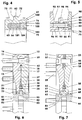
- the Figure 1 shows the braking and / or clamping device without the supporting machine-side base body (1), cf. Figure 2 or 3 , and without the shaft to be braked and / or clamped (5).
- the external actuation assembly (10) shows as the front side (19) an installation joint, via which it is screwed to the base body (1) by means of the fastening screws (59).
- the actuation assembly (10) surrounds a shaft connection assembly (60) which adapts a clamping flange (62) to the shaft (5).
- the actuating assembly (10) has two annular disks (11, 12) which are elastic in some areas and which are joined in an assembly joint (16) and which rest on the clamping flange (62) like tongs.
- the washers (11, 12) also enclose a pressure space (37). If the latter is pressurized with oil, the pincer-like clasping of the clamping flange (62) is released.
- the pressure chamber (37) has a volume which is smaller than one seventy-fifth of the envelope volume of the device.
- the envelope volume corresponds to a given pipe volume, which has the device width as the pipe length, the outer device diameter as the outer diameter and the diameter of the shaft (5) as the inner diameter.
- the actuating assembly (10) has two plate-like ring disks (11, 12) resting against one another, which e.g. enclose narrow-column, annular pressure chamber (37).
- Each ring disk (11, 12) is in the undeformed state a flat disk with an inside diameter of e.g. approx. 280 mm and an outer diameter of 388 mm.
- the maximum thickness of the disc is e.g. at 11 mm.
- the ring washer (11, 12) is made of a quenched and tempered steel, e.g. 42CrMoS4. It is divided into three areas (13, 21, 26) which adjoin one another in the radial direction. An inner area is the clamping zone (26). This is followed by a bending zone (21), which in turn opens into an outer area, the contact zone (13).
- the contact zone (13) each has a flat end face (15) over which the annular disks (11, 12) lie close to one another in the assembled state. It has, for example, a bore every 5 degrees of which only two are centering bores (44) and two further threaded inlet bores (41).
- the remaining through holes are holes (45) with a countersink according to DIN 974-1 or threaded holes (46).
- To Figure 1 has the front washer (11) in the upper half - with the exception of the centering hole (44) - only the holes (45), while the lower half Half - also with the exception of the centering hole (44) - in addition to 21 threaded holes (46) also has 12 holes (45) with countersinking. In total, 24 fastening screws (59) hold the device on the base body (1).
- a housing screw (57) is positioned between a first and a second fastening screw (59). Three housing screws (57) are arranged between the second and a third fastening screw (59). The screwing pattern is repeated from the third fastening screw (59).
- a circumferential distribution half-groove (18) is arranged which, together with the distribution half-groove (17) of the other annular disk (11), forms the distribution groove.
- An O-ring (52) is located in the distribution groove (17, 18).
- the hydraulic oil-free assembly joint (16) is located in the radial direction outside the distribution groove (17, 18).
- the gap-shaped pressure space (37) is located radially within the distribution groove (17, 18). It is limited radially outward by the O-ring (52). Towards the center line (9), the pressure space (37) is closed by a double lip seal (50).
- the double lip seal (50) sits in an annular channel - at least approximately rectangular in cross section - which is formed by a half-ring channel (35, 36) per annular disk (11, 12) becomes.
- the half-ring channel (35, 36) is located in the transition zone between the bending zone (21) and the clamping zone (26).
- the double lip seal (50) it is made for example from a polyurethane with a Shore D hardness of 57, has two radially outwardly oriented sealing lips (51), which are each on the groove base of the half-ring channels (35) and (36) due to their own Apply elasticity or additionally through the internal pressure in the pressure chamber (37).
- the double lip seal (50) has a metallic stiffening ring (58) on its flank oriented towards the center line (9). The latter is intended to prevent parts of the seal (50) - especially if it has a hardness of less than 50 Shore D, for example - from becoming permanently stuck in the gap (37) located between the annular disks (11, 12) in the clamping zone (26).
- the stiffening ring (58) is either loosely inserted into the annular channel (35, 36) or it is materially connected to the sealing ring (50), for example by gluing or by vulcanization.
- the respective distribution half-groove (17, 18) is located in the edge area of the greatest bending moment in the case of annular disks (11, 12) loaded with oil pressure.
- the distribution half-groove (17, 18) has a radius of 2 mm towards the installation joint (16). Towards the gap (37) the radius measures 1.25 mm.
- a spacer disk (23) is arranged between the two annular disks (11, 12) as an intermediate element.
- a second sealing ring (50) rests on the spacer (23), the sealing lips of which face the first - in Figure 7 below - the sealing ring (50) are oriented.
- FIG. 1 to 3 are located in the contact zone (13) at least two each coaxially opposite threaded inlet bores (41).
- the M5 threads used here are slowing down Figure 3 each have a sealing plug (55) and a hydraulic adapter (56).
- Each threaded inlet bore (41) intersects a radial distribution bore (42).
- These distribution bores (42) are each closed to the outside by a clamping sleeve (53).
- a compression ball (54) is wedged into the bore of the clamping sleeve (53) and permanently fixes the clamping sleeve (53) in the individual radial distribution bore (42), at least in an oil-tight manner.
- Each radial distribution bore (42) meets, for example, perpendicularly on an axial distribution bore (43) which opens into the pressure chamber (37).
- the distribution bores (42, 43) here have a diameter of 2.5 mm.
- the hydraulic oil flowing in via the hydraulic adapter (56) e.g. an oil of the type HLP 46 according to DIN 51524, part 2, which has a viscosity of 46 ⁇ 2 mm 2 / s at 40 ° Celsius, is distributed among other things via the distribution groove (17, 18) quickly in the pressure chamber (37).
- the annular disk (11, 12) has a recess (29) towards the assembly joint (16), which creates the, for example, planar friction surface (31, 32) on the jaws (27, 28).
- the individual friction surface (31, 32) has a depth of 3 mm with an average radius of 142.3 mm.
- the jaw width of the individual pliers jaws (27, 28) is 4.2 mm, for example.
- the maximum width of the friction surface (31, 32) is 6 mm, for example.
- the friction surfaces (31, 32) have inwardly directed surface normals (33). The latter show after Figure 6 in the direction of a plane in which the assembly plane (16) also lies.
- the friction surfaces can also have the shape of a truncated cone jacket or a partial area of a torus.
- the elastic bending zone (21) lies between the clamping zone (26) and the contact zone (13). Their wall thickness decreases with decreasing device radius from e.g. 11 mm by 6 mm. The dimensional rigidity of the annular disk (11, 12) thus decreases almost continuously in the direction of the clamping zone (26). The transitions between zones (26) and (21) and zones (21) and (13) are rounded with large radii. The two radii are in the order of magnitude of twice the maximum wall thickness of the individual annular disk (11, 12).
- the bending zone (21) is set back compared to the contact zone (13) - in the area of the outer end wall (14) - by 0.2 mm compared to the installation joint, so that the deformation of the bending zone (21) does not affect that between the base body (1) and the Enter the installation joint located in the annular disk (11).
- the coupling area (61) consists of a flange core (63), an annular body which carries the, for example, centrally formed clamping flange (62) radially on the outside.
- the clamping flange (62) for example 4.4 mm wide, protrudes radially from the flange core (63) by, for example, 4 mm as a circumferential web. Its end faces form, for example, flat friction surfaces (71, 72).
- the latter like the friction surfaces (31, 32) of the tong jaws (27, 28), are usually finely machined.
- the friction surfaces (71, 72) have outwardly directed surface normals (73).
- the friction surfaces (31, 32) or the friction surfaces (71, 72) can have a surface structure.
- this is created by sandblasting or a diamond or sapphire coating.
- Such coatings have a layer thickness of e.g. 0.038 mm.
- the average grain size of the coating base material at this layer thickness is 30 ⁇ m.
- the clamping flange (62) merges into the flange core (63) on both sides via relief notches (65), cf. Figure 7 .
- the relief notches (65) are 2.8 mm wide, 0.65 mm deep and each have 1 mm radii on both sides.
- the flange core (63) has a central stepped bore (112) which carries a radial seat surface (113) and a flat flange surface (114) on the flange collar side.
- the axial mounting flange (111) there are several bores (115) parallel to the center line (9) with cylinder countersinks.
- these bores (115) are screws (119), via which the connection assembly (110) is screwed directly to the shaft (5) on its shaft collar (6).
- the clamping flange (62) can optionally also have transverse grooves which extend to the flange base (64). In this way, instead of a completely circumferential clamping flange (62), several or many clamping webs protrude radially from the flange core (63) in order to protrude between the tong jaws (27, 28). The clamping webs can - to influence the device noise - protrude from the flange core (63) at a constant or irregular pitch.
- the Figures 1 and 2 show a shaft connection assembly (80) with a double radial clamping flange.
- the flange core (63) has a central, cylindrical bore (66), in which a groove (85) is worked in the center, which has a rectangular cross-section, for example.
- a clamping mechanism (76) two clamping flanges (81, 82) are created in the shaft connection area (75).
- the groove width is, for example, 7 mm with a groove depth of, for example, 7.35 mm.
- the groove (85) has two radii of curvature of 1.5 mm.
- a material web (86) of 1.5 to 2 mm is located between the individual relief notches (65) and the closest rounded groove.
- the flange core (63) is drilled through in the area of the clamping flanges (81, 82) so that Figure 2 to the right of the groove (85) there are in pairs many bores (87) with countersinking and to the left of the groove (85) a corresponding number of threaded bores (88), e.g. M4. In the exemplary embodiment, 48 screws (89) are screwed in.
- the clamping surface (66) the inner diameter of which here e.g. 260 mm, equipped with a diamond or sapphire coating, cf. any existing coating of the friction surfaces (31, 32) or (71, 72).
- a diamond paste can also be introduced into the assembly joint between the clamping surface (66) and the shaft surface to improve the adhesion.
- the clamping surface (66) and / or the shaft surface in the seat area of the flange core (63) can have a friction structure, e.g. is lasered.
- FIG Figure 4 An alternative shaft connection assembly (60) is shown in FIG Figure 4 shown. It shows a connection assembly (100) with a displacement clamping sleeve.
- the core flange (63) has, as a shaft connection area (75), a circumferential end groove (102) which follows Figure 4 is incorporated into the flange core (63) from the right end.
- a fine thread (103) is cut into the outer wall of the end groove (102), for example 7 mm deep.
- an elastic for example 1.4 mm thick, clamping sleeve wall (101) of the displacement clamping sleeve remains.
- An annular elastomer body (104) is inserted into the end groove (102) as a displacement body. Its width covers 55 to 70% of the flange core width. Its wall thickness measures e.g. 5 mm.
- a threaded ring (105) e.g., a threaded ring (105)
- the elastomer body (104) is compressed in such a way that the clamping sleeve wall (101) clings to the shaft (5) in a torsion-proof manner.
- the elastomer body (104) is made, for example, from the acrylonitrile-butadiene rubber NBR. Its Shore A hardness is between 64 and 68.
- the Figure 5 shows a partial section of a shaft connection assembly (90) with a shrink disk connection.
- the one Flange core (63) is a relatively thin ring which tapers outward in diameter on both sides.
- the central clamping flange (62) protrudes here about 11.5 mm in the radial direction over the truncated cone shells (91).
- the annular cone clamping elements (93, 94) sit on both sides of these truncated cone shells (91) in order, together with the flange core (63), to form a shrink disk serving as a clamping mechanism.
- the ring cone clamping elements (93, 94) are rings, the central recess (92) of which is conically designed to match the truncated cone shells (91).
- the cone angle is e.g. 5 degrees.
- the annular cone clamping elements (93, 94) are each provided on the end faces which are oriented towards the clamping flange (62) with e.g. Make approx. 4.3 mm wide and 10 mm deep grooves (97) at the narrowest point. The width of the indentations (97) increases steadily with increasing radius.
- Both annular cone clamping elements (93, 94) have coaxial bores (95, 96) for the screws (99) with which the annular cone clamping elements (93, 94) are pressed against the thin-walled flange core (63) with axial and radial tension. That after Figure 5
- the left ring cone clamping element (93) has a threaded hole (96)
- the right ring cone clamping element (94) is provided with a hole (95) with a counterbore.
- the shrink disk has, for example, 24 screws (99). All screws also pass through the clamping flange (62) between the friction surfaces (31, 32) and the flange core (63), which has a concentric bore (98) to the bores (95, 96).
- This braking and / or clamping device is delivered in combination with the selected shaft connection assembly (80, 90, 100, 110).
- the respective shaft connection assembly (80, 90, 100, 110) sits coaxially in the actuation assembly (10).
- the shaft connection assembly (80, 90, 100) is pushed onto the shaft (5) and attached there - usually detachable - directly to the mounting surface (3) of the base body (1).
- the fastening screws (59) are inserted into the corresponding holes on the base body and screwed there.
- the shaft (5) is clamped against the base body (1).
- the pressure chamber (37) has no significant oil pressure, since the oil inlet is relieved into the oil tank via a valve (not shown).
- the ring disks (11, 12) are pre-tensioned by their pincer jaws (27, 28) on the clamping flange (62), cf. Figure 2.
- the preload results from the spring rate of the bulged annular disks (11, 12).
- the level of the spring rate is a function of the choice of material on the ring washer side and the geometry of the bending zone (21).
- the braking or holding torque generated is 3000 ⁇ 200 Nm.
- the annular disks (11, 12) would only be in the completely relaxed state if there were no clamping flange (62) between the tong jaws (27, 28). Then, in the exemplary embodiment, the pressure chamber (37) would be a gap with a constant gap width.
- the hydraulic adapter (56), cf. Figure 3 the pressure oil pressure in the pressure chamber (37) is increased to 100 to 150 * 10 5 Pa, for example. From the hydraulic adapter (56), the pressure increase is propagated via the distribution bores (42) and (43) into the pressure chamber (37). The annular disks (11, 12) buckle in the elastic bending zones (21), cf. FIG. 3. In this case, each clamping zone (26) moves outwards in relation to the contact zone (13), which remains stationary, essentially in the axial direction. The tong jaws (27, 28) lift off the clamping flange (62) in the direction of the arrows (47).
- the friction surfaces (31, 32) on the actuation assembly side move away from the friction surfaces (71, 72) on the shaft connection assembly side, so that there is no longer any contact between the shaft (5) and the base body (1).
- the clearance per friction surface pairing (31) to (71) and (32) to (72), i.e. the distance between the previously contacting friction surfaces, is now between 0.3 and 0.5 mm.
- the device is designed for 5 to 10 million opening and closing cycles.
Landscapes
- Engineering & Computer Science (AREA)
- General Engineering & Computer Science (AREA)
- Mechanical Engineering (AREA)
- Physics & Mathematics (AREA)
- Electromagnetism (AREA)
- Clamps And Clips (AREA)
- Braking Arrangements (AREA)
Description
- Die Erfindung betrifft eine Brems- und/oder Klemmvorrichtung für eine gegenüber einem Grundkörper geführte Welle mit einer Betätigungsbaugruppe und mit einer Wellenanbindungsbaugruppe.
- Aus der
DE 10 2008 020 518 B4 ist eine Brems- und/oder Klemmvorrichtung für Wellen bekannt, bei der um die Welle herum z.B. zehn auf Reibgehemme wirkende Schiebekeilgetriebe angeordnet sind. Die Schiebekeile werden mittels Pneumatikzylinder verstellt, um die einzelnen Bremsbacken gegen die Welle zu pressen. Diese Konstruktion hat einen hohen Bauraumbedarf und wirkt direkt auf die Welle. - Die
DE 11 12 873 B beschreibt eine Klemmeinrichtung mit axial beweglichen Klemmbacken zum Feststellen einer Werkstückspindel. Dazu hat die Werkstückspindel eine umlaufende Ringnut, in die ein in Axialrichtung hydraulisch dehnbarer Klemmring hineinragt. Wird der Innenraum des Klemmrings - zum Feststellen - mit Druck beaufschlagt, legen sich die beiden axialen Wandungen des Klemmrings an die beiden axialen Wandungen der Ringnut an. - Der vorliegenden Erfindung liegt die Problemstellung zugrunde, eine derartige Brems- und/oder Klemmvorrichtung zu entwickeln, die auch bei einem großen Durchmesser eine geringe Baubreite aufweist, aus wenigen Bauteilen besteht und zudem einfach, sicher und wartungsfrei funktioniert.
- Diese Problemstellung wird mit den Merkmalen des Hauptanspruchs gelöst. Dabei weist die Betätigungsbaugruppe zwei Ringscheiben auf, die in einer gemeinsamen Kontaktzone direkt oder über ein Zwischenelement dicht aneinanderliegen und jeweils außerhalb der Kontaktzone bereichsweise eine elastisch beulbare Biegezone haben. Die Ringscheiben weisen jeweils in zwei einander gegenüberliegenden Klemmzonen jeweils Zangenbacken mit Reibflächen auf, deren Flächennormalen nach innen gerichtet sind. Zwischen den Ringscheiben liegt ein abgedichteter Druckraum, der zum elastischen Auseinanderdrücken der Reibflächen mit Druckmedium befüllbar ist. Die Wellenanbindungsbaugruppe weist einen Kupplungsbereich auf, der zwei voneinander beabstandete Reibflächen hat, deren Flächennormalen nach außen weisen. Die Wellenanbindungsbaugruppe weist einen Wellenanbindungsbereich auf. Der Wellenanbindungsbereich ist entweder direkt oder indirekt über einen Spannmechanismus am Kupplungsbereich angeordnet. Bei entlastetem Druckraum sind die Reibflächen der Betätigungsbaugruppe an den Reibflächen der Wellenanbindungsbaugruppe unter Bereitstellung der Klemm- und/oder Bremskraft angelegt.
- Der Gegenstand der vorliegenden Erfindung ist eine mindestens zweiteilige Brems- und/oder Klemmvorrichtung für Wellen. Das eine Teil wird als Adapter auf die Welle montiert und an dieser festgeklemmt oder festgeschraubt, um mit dieser zu rotieren. Es hat beispielsweise einen radial abstehenden Klemmflansch. Das andere Teil ist eine Art von Zange, die an einem ortsfesten, z.B. die vorgenannte Welle lagernden Maschinenteil befestigt ist. Die Zange hat z.B. ringförmige Zangenbacken, mit denen sie die Stirnseiten des wellenseitigen Flansches lose umfassen oder drehfest umgreifen kann. Die die Welle bremsenden oder klemmenden Vorrichtungsteile liegen nicht auf der Außenwandung der Welle an, d.h. die Arbeitsfuge der Brems- und/oder Klemmvorrichtung ist identisch mit der Wandung der Welle.
- Die ringförmigen Zangenbacken der Vorrichtung lassen sich vereinfacht als zwei Tellerfedern beschreiben, deren beiden Innenränder einander zugewandt sind, während die im Durchmesser größeren Außenränder in Axialrichtung weit auseinanderliegen. Zwischen die Innenränder, die eine Klemmzone bilden, wird der Klemmflansch eingelegt. Werden nun die Außenränder, die die Kontaktzone darstellen, in Axialrichtung aufeinander zubewegt, werden die im Durchmesser kleineren Innenränder den Klemmflansch zum Halten federgespannt zangenartig einklemmen. Die Tellerfedern werden bei der Montage der Vorrichtung so fixiert, dass sich der Abstand der Außenränder nicht mehr ändern lässt. Um nun den Klemmflansch wieder freizugeben, werden die Tellerfedern mit Öldruck auseinandergepresst. Die Innenränder lösen sich vom Klemmflansch. Die bisher zum Klemmen wenig vorgespannten Tellerfedern werden somit zum Lösen noch stärker gespannt bzw. verformt.
- Alternativ lässt sich die Vorrichtung auch so gestalten, dass der Klemmflansch in der Bohrung eines rotierenden Ringes angebracht wird, während die ortsfest gelagerte Zange räumlich innerhalb des rotierenden Ringes dessen nach innen kragenden Klemmflansch umgreift.
- Weitere Einzelheiten der Erfindung ergeben sich aus den Unteransprüchen und der nachfolgenden Beschreibung mindestens einer schematisch dargestellten Ausführungsform.
- Figur 1:
- perspektivische Ansicht einer Brems- und/oder Klemmvorrichtung mit einer auf einem Doppelradialspannflansch basierenden Wellen-Naben-Verbindung;
- Figur 2:
- Teillängsschnitt zu
Figur 1 ; - Figur 3:
- Teillängsschnitt zu
Figur 1 , jedoch mit ungeradem und/oder flexiblem Führungselement; - Figur 4:
- Teillängsschnitt durch eine Wellen-Naben-Verbindung mit Verdrängerspannhülse, vergrößert;
- Figur 5:
- Teillängsschnitt durch eine Wellen-Naben-Verbindung mit Ringfederspannsatz, vergrößert;
- Figur 6:
- Teillängsschnitt der Brems- und/oder Klemmvorrichtung durch die Grundkörperverschraubung;
- Figur 7:
- Teillängsschnitt der Brems- und/oder Klemmvorrichtung durch die Ringscheibenverschraubung.
- Die
Figur 1 zeigt die Brems- und/oder Klemmvorrichtung ohne den tragenden maschinenseitigen Grundkörper (1), vgl.Figur 2 oder 3 , und ohne die abzubremsende und/oder festzuklemmende Welle (5). Die außenliegende Betätigungsbaugruppe (10) zeigt als Vorderseite (19) eine Einbaufuge, über die sie mittels der Befestigungsschrauben (59) am Grundkörper (1) angeschraubt wird. Die Betätigungsbaugruppe (10) umgibt eine Wellenanbindungsbaugruppe (60), die einen Klemmflansch (62) an der Welle (5) adaptiert. Die Betätigungsbaugruppe (10) hat zwei in einer Montagefuge (16) gefügte, bereichsweise elastische Ringscheiben (11, 12), die zangenartig am Klemmflansch (62) anliegen. Die Ringscheiben (11, 12) umschließen zudem einen Druckraum (37). Wird letzterer mit Drucköl beaufschlagt, löst sich die zangenartige Umklammerung des Klemmflansches (62). - Der Druckraum (37) hat ein Volumen, das kleiner ist als ein fünfundsiebzigstel des Hüllvolumens der Vorrichtung. Das Hüllvolumen, der in den Figuren dargestellten Variante, entspricht einem gegebenen Rohrvolumen, das als Rohrlänge die Vorrichtungsbreite, als Außenduchmesser den äußeren Vorrichtungsdurchmesser und als Innendurchmesser den Durchmesser der Welle (5) hat.
- Die Betätigungsbaugruppe (10) weist zwei aneinander anliegende plattenartige Ringscheiben (11, 12) auf, die den z.B. schmalspaltigen, ringförmigen Druckraum (37) umschließen. Jede Ringscheibe (11, 12) ist im unverformten Zustand eine ebene Scheibe mit einem Innendurchmesser von z.B. ca. 280 mm und einem Außendurchmesser von 388 mm. Die maximale Dicke der Scheibe liegt z.B. bei 11 mm. Die Ringscheibe (11, 12) ist aus einem Vergütungsstahl, z.B. 42CrMoS4, gefertigt. Sie ist in drei Bereiche (13, 21, 26) aufgeteilt, die in Radialrichtung aneinander anschließen. Ein innerer Bereich ist die Klemmzone (26). An sie schließt sich eine Biegezone (21) an, die wiederum in einen äußeren Bereich, die Kontaktzone (13), mündet.
- Die Kontaktzone (13) hat jeweils eine plane Stirnfläche (15), über die die Ringscheiben (11, 12) im montierten Zustand dicht aneinander liegen. Sie weist z.B. alle 5 Winkelgrade eine Bohrung auf, von denen nur zwei Zentrierbohrungen (44) und zwei weitere Zulaufgewindebohrungen (41) sind. Die restlichen Durchgangsbohrungen sind Bohrungen (45) mit einer Senkung nach DIN 974-1 oder Gewindebohrungen (46). Nach
Figur 1 hat die vordere Ringscheibe (11) in der oberen Hälfte - mit Ausnahme der Zentrierbohrung (44) - nur die Bohrungen (45), während die untere Hälfte - auch mit Ausnahme der Zentrierbohrung (44) - neben 21 Gewindebohrungen (46) noch 12 Bohrungen (45) mit Senkung auf-weist. In der Summe halten 24 Befestigungsschrauben (59) die Vorrichtung am Grundkörper (1). - Jeweils zwischen einer ersten und einer zweiten Befestigungsschraube (59) ist eine Gehäuseschraube (57) positioniert. Zwischen der zweiten und einer dritten Befestigungsschraube (59) sind drei Gehäuseschrauben (57) angeordnet. Ab der dritten Befestigungsschraube (59) wiederholt sich das Verschraubungsmuster.
- Die nach
Figur 1 hinten gelegene Ringscheibe (12) ist gegenüber der vorderen Ringscheibe (11) um die in der Montagefuge (16) liegende fiktive Achse (8) um 180 Winkelgrade geschwenkt und dann zusätzlich um die Mittellinie (9) nochmals um 180 Winkelgrade gedreht. Durch die vorliegende Anordnung der Bohrungen (41, 44, 45, 46) können beide Ringscheiben (11, 12) baugleich ausgeführt sein. - In der Innenwandung (15) der Ringscheibe (12) ist in der Kontaktzone (13), vgl.
Figur 6 , eine umlaufende Verteilhalbnut (18) angeordnet, die zusammen mit der Verteilhalbnut (17) der anderen Ringscheibe (11) die Verteilnut bildet. In der Verteilnut (17, 18) liegt ein O-Ring (52). In Radialrichtung außerhalb der Verteilnut (17, 18) befindet sich die hydraulikölfreie Montagefuge (16). Radial innerhalb der Verteilnut (17, 18) liegt der spaltförmige Druckraum (37). Er wird radial nach außen durch den O-Ring (52) begrenzt. Zur Mittellinie (9) hin wird der Druckraum (37) durch eine Doppellippendichtung (50) abgeschlossen. Die Doppellippendichtung (50) sitzt in einem - im Querschnitt zumindest annähernd rechteckigen - Ringkanal, der pro Ringscheibe (11, 12) durch einen Halbringkanal (35, 36) gebildet wird. Der Halbringkanal (35, 36) befindet sich in der Übergangszone zwischen der Biegezone (21) und der Klemmzone (26). - Die Doppellippendichtung (50), sie ist z.B. aus einem Polyurethan mit einer Shore D-Härte von 57 gefertigt, hat zwei radial nach außen orientierte Dichtlippen (51), die sich jeweils am Nutgrund der Halbringkanäle (35) und (36) aufgrund der eigenen Elastizität oder zusätzlich durch den im Druckraum (37) anstehenden Innendruck anlegen. Nach den
Figuren 5 und 6 weist die Doppellippendichtung (50) an ihrer zur Mittellinie (9) hin orientierten Flanke einen metallischen Versteifungsring (58) auf. Letzterer soll verhindern, dass sich Teile der Dichtung (50) - zumal wenn sie beispielsweise eine Härte unter 50 Shore D hat - dauerhaft in den zwischen den Ringscheiben (11, 12) gelegenen Spalt (37) in der Klemmzone (26) festsetzen. Der Versteifungsring (58) ist entweder lose in den Ringkanal (35, 36) eingelegt oder er ist stoffschlüssig mit dem Dichtring (50) verbunden, z.B. durch Verkleben oder durch Vulkanisieren. - Die jeweilige Verteilhalbnut (17, 18) befindet sich bei öldruckbelasteten Ringscheiben (11, 12) im Randbereich des größten Biegemoments. Um die durch die z.B. 1,2 mm tiefe Verteilhalbnut (17, 18) entstehende Kerbspannung so niedrig wie möglich zu halten, hat der Querschnitt der Verteilhalbnut (17, 18) zur Montagefuge (16) hin einen Radius von 2 mm. Zum Spaltraum (37) hin misst der Radius 1,25 mm.
- In der Variante nach
Figur 7 ist zwischen den beiden Ringscheiben (11, 12) als Zwischenelement eine Distanzscheibe (23) angeordnet. An der Distanzscheibe (23) legt sich beispielsweise ein zweiter Dichtring (50) an, dessen Dichtlippen in Richtung des ersten - inFigur 7 unten liegenden - Dichtrings (50) orientiert sind. - Gemäß der
Figuren 1 bis 3 befinden sich in der Kontaktzone (13) mindestens jeweils zwei einander koaxial gegenüberliegende Zulaufgewindebohrungen (41). Die hier verwendeten M5-Gewinde neh men nachFigur 3 jeweils einen Verschlussstopfen (55) und einen Hydraulikadapter (56) auf. Jede Zulaufgewindebohrung (41) schneidet eine radiale Verteilbohrung (42). Nach außen hin sind diese Verteilbohrungen (42) jeweils durch eine Klemmbüchse (53) verschlossen. In die Bohrung der Klemmbüchse (53) ist jeweils eine Stauchkugel (54) eingestemmt, die die Klemmbüchse (53) in der einzelnen radialen Verteilbohrung (42) zumindest öldicht dauerhaft fixiert. Jede radiale Verteilbohrung (42) trifft z.B. senkrecht auf eine axiale Verteilbohrung (43), die in den Druckraum (37) mündet. Die Verteilbohrungen (42, 43) haben hier einen Durchmesser von 2,5 mm. Das über den Hydraulikadapter (56) einströmende Hydrauliköl, z.B. ein Öl vom Typ HLP 46 nach DIN 51524, Teil 2, das bei 40° Celsius eine Viskosität von 46 ± 2 mm2/s aufweist, verteilt sich u.a. über die Verteilnut (17, 18) schnell im Druckraum (37). - Die Klemmzone (26), die zu der jeweiligen Wellenanbindungsbaugruppe (60) hin orientiert ist, weist die umlaufenden Zangenbacken (27, 28) auf. Zur Montagefuge (16) hin hat die Ringscheibe (11, 12) eine Eindrehung (29), wodurch die beispielsweise plane Reibfläche (31, 32) an den Zangenbacken (27, 28) entsteht. Im Ausführungsbeispiel hat die einzelne Reibfläche (31, 32) bei einem mittleren Radius von 142,3 mm eine Tiefe von 3 mm. Die Backenbreite des einzelnen Zangenbackens (27, 28) beträgt hier z.B. 4,2 mm. In der Klemmzone (26) beträgt die maximale Breite der Reibfläche (31, 32) z.B. 6 mm. Die Reibflächen (31, 32) haben nach innen gerichtete Flächennormalen (33). Letztere zeigen nach
Figur 6 in Richtung einer Ebene, in der auch die Montageebene (16) liegt. - Anstelle der planen Reibflächen (31, 32), die zudem parallel zur Montagefuge orientiert sind, können die Reibflächen auch die Gestalt eines Kegelstumpfmantels oder eines Teilbereiches eines Torus haben.
- Zwischen der Klemmzone (26) und der Kontaktzone (13) liegt die elastische Biegezone (21). Ihre Wandstärke sinkt mit abnehmendem Vorrichtungsradius von z.B. 11 mm auf 6 mm. Die Formsteifigkeit der Ringscheibe (11, 12) nimmt somit in Richtung Klemmzone (26) nahezu stetig ab. Die Übergänge zwischen den Zonen (26) und (21) sowie den Zonen (21) und (13) sind mit großen Radien ausgerundet. Die beiden Radien liegen in der Größenordnung der doppelten maximalen Wandstärke der einzelnen Ringscheibe (11, 12). Die Biegezone (21) ist gegenüber der Kontaktzone (13) - im Bereich der außenliegenden Stirnwandung (14) - um 0,2 mm gegenüber Einbaufuge zurückgenommen, um die Verformung der Biegezone (21) nicht in die zwischen dem Grundkörper (1) und der Ringscheibe (11) gelegenen Einbaufuge einzutragen.
- Die Zangenbacken (27, 28) der Betätigungsbaugruppe (10) liegen bei geklemmter Brems- und/oder Klemmvorrichtung an einem Klemmflansch (62) des Kupplungsbereiches (61) einer Wellenanbindungsbaugruppe (60) an.
- In den
Figuren 1 und 3 bis 5 sind vier verschiedene Wellenanbindungsbaugruppen (80, 90, 100, 110) dargestellt. DieFigur 3 zeigt als Wellenanbindungsbaugruppe eine Anbindungsbaugruppe mit Axialmontageflansch (110). Bei dieser Variante besteht der Kupplungsbereich (61) aus einem Flanschkern (63), einem ringförmigen Körper, der radial außen den z.B. zentral angeformten Klemmflansch (62) trägt. Der z.B. 4,4 mm breite Klemmflansch (62) steht als umlaufender Steg vom Flanschkern (63) radial um z.B. 4 mm ab. Seine Stirnflächen bilden z.B. ebene Reibflächen (71, 72). Letztere sind in der Regel, wie auch die Reibflächen (31, 32) der Zangenbacken (27, 28), fein bearbeitet. Die Reibflächen (71, 72) haben nach außen gerichtete Flächennormalen (73). - Alternativ können die Reibflächen (31, 32) oder die Reibflächen (71, 72) eine Oberflächenstruktur aufweisen. Beispielsweise entsteht diese durch Sandstrahlen oder durch eine Diamant- oder Saphirbeschichtung. Derartige Beschichtungen weisen eine Schichtstärke von z.B. 0,038 mm auf. Die durchschnittliche Korngröße des Beschichtungsgrundmaterials liegt bei dieser Schichtstärke bei 30 µm.
- Der Klemmflansch (62) geht in den Flanschkern (63) beidseitig über Entlastungskerben (65) über, vgl.
Figur 7 . Die Entlastungskerben (65) sind 2,8 mm breit, 0,65 mm tief und weisen beidseitig jeweils 1 mm-Radien auf. - Der Flanschkern (63) hat zur Ausbildung eines Axialmontageflansches (111) eine zentrale Stufenbohrung (112), die eine radiale Sitzfläche (113) und flanschbundseitig eine plane Bundfläche (114) trägt. Im Bereich des Axialmontageflansches (111) befinden sich mehrere zur Mittellinie (9) parallele Bohrungen (115) mit Zylindersenkungen. In diesen Bohrungen (115) sitzen Schrauben (119), über die die Anbindungsbaugruppe (110) direkt mit der Welle (5) an deren Wellenbund (6) verschraubt ist.
- Der Klemmflansch (62) kann ggf. auch Quernuten aufweisen, die bis an den Flanschgrund (64) reichen. Auf diese Weise stehen, anstatt eines vollständig umlaufenden Klemmflansches (62), mehrere oder viele Klemmstege vom Flanschkern (63) radial ab, um zwischen die Zangenbacken (27, 28) hineinzuragen. Die Klemmstege können dabei - zur Beeinflussung des Vorrichtungsgeräusches - mit konstanter oder unregelmäßiger Teilung vom Flanschkern (63) abstehen.
- Die
Figuren 1 und2 zeigen eine Wellenanbindungsbaugruppe (80) mit einem Doppelradialspannflansch. Hier hat der Flanschkern (63) eine zentrale, zylindrische Bohrung (66), in die hier mittig eine Nut (85) eingearbeitet ist, die z.B. einen rechteckigen Querschnitt hat. So entstehen zur Herstellung eines Spannmechanismus (76) im Wellenanbindungsbereich (75) zwei Spannflansche (81, 82). Die Nutbreite beträgt z.B. 7 mm bei einer Nuttiefe von z.B. 7,35 mm. Die Nut (85) hat zwei Ausrundungsradien von 1,5 mm. Zwischen der einzelnen Entlastungskerbe (65) und der nächstgelegenen Nutausrundung liegt ein Materialsteg (86) von 1,5 bis 2 mm. Der Flanschkern (63) ist im Bereich der Spannflansche (81, 82) so durchbohrt, dass sich nachFigur 2 rechts neben der Nut (85) paarweise viele Bohrungen (87) mit Kegelsenkung und links neben der Nut (85) entsprechend viele Gewindebohrungen (88), z.B. M4, befinden. Im Ausführungsbeispiel sind 48 Schrauben (89) eingeschraubt. - Ggf. ist die Spannfläche (66), deren Innendurchmesser hier z.B. 260 mm beträgt, mit einer Diamant- oder Saphirbeschichtung ausgestattet, vgl. ggf. vorhandene Beschichtung der Reibflächen (31, 32) oder (71, 72). Anstelle der festhaftenden Beschichtung, kann auch in die Montagefuge zwischen der Spannfläche (66) und der Wellenoberfläche eine Diamantpaste zum Verbessern der Haftung eingebracht werden. Alternativ kann die Spannfläche (66) und/oder die Wellenoberfläche im Sitzbereich des Flanschkerns (63) über eine Reibstruktur verfügen, die z.B. aufgelasert wird.
- Werden nach dem Aufschieben der Vorrichtung auf die Welle (5) an den vorgesehenen Einbauplatz die Schrauben (89) festgeschraubt, so werden die Spannflansche (81, 82) gegeneinander gezogen. Hierdurch legen sich aufgrund der gelenkartigen Nachgiebigkeit der Materialstege (86) des Flanschkerns (63) die Spannflansche (81, 82) über die Tragkanten (83), vgl.
Figur 6 , primär unter radialer Verspannung fest an. - Eine alternative Wellenanbindungsbaugruppe (60) ist in
Figur 4 dargestellt. Sie zeigt eine Anbindungsbaugruppe (100) mit Verdrängerspannhülse. Hier weist der Kernflansch (63) als Wellenanbindungsbereich (75) eine umlaufende Stirnnut (102) auf, die nachFigur 4 von der rechten Stirnseite aus in den Flanschkern (63) eingearbeitet ist. In die außenliegende Wandung der Stirnnut (102) ist z.B. 7 mm tief ein Feingewinde (103) eingeschnitten. Zur Welle (5) bzw. zur Bohrung (66) hin bleibt eine elastische, z.B. 1,4 mm dicke, Klemmhülsenwandung (101) der Verdrängerspannhülse stehen. - In die Stirnnut (102) ist als Verdrängerkörper ein ringförmiger Elastomerkörper (104) eingesetzt. Seine Breite überdeckt 55 bis 70% der Flanschkernbreite. Seine Wandstärke misst z.B. 5 mm. Zur Herstellung eines klemmenden Spannmechanismus (76) wird bei der Montage der Anbindungsbaugruppe (100) auf die Welle (5) in das Innengewinde (103) ein Gewindering (105), z.B. mittels Hakenschlüssel, eingeschraubt. Der Elastomerkörper (104) wird so verdichtet, dass sich die Klemmhülsenwandung (101) verdrehfest an der Welle (5) anschmiegt.
- Der Elastomerkörper (104) ist beispielweise aus dem AcrylnitrilButadien-Kautschuk NBR hergestellt. Seine Härte in Shore A liegt zwischen 64 und 68.
- Die
Figur 5 zeigt einen Teilschnitt einer Wellenanbindungsbaugruppe (90) mit einer Schrumpfscheibenverbindung. Hier ist der Flanschkern (63) ein relativ dünner Ring, der sich beidseitig nach außen im Durchmesser verjüngt. Rechts und links neben dem zentralen Klemmflansch (62) weist er als radiale Außenwandung zwei Kegelstumpfmäntel (91) auf. Der zentrale Klemmflansch (62) ragt hier ca. 11,5 mm in Radialrichtung über die Kegelstumpfmäntel (91) über. - Auf diesen Kegelstumpfmänteln (91) sitzen beidseitig die Ringkegelspannelemente (93, 94) auf, um zusammen mit dem Flanschkern (63) eine als Spannmechanismus dienende Schrumpfscheibe zu bilden. Die Ringkegelspannelemente (93, 94) sind Ringe, deren zentrale Ausnehmung (92) konisch passend zu den Kegelstumpfmänteln (91) gestaltet ist. Der Konuswinkel beträgt z.B. 5 Winkelgrade. Um Platz für die Zangenbacken (27, 28) der Betätigungsbaugruppe (10) zu lassen, sind die Ringkegelspannelemente (93, 94) jeweils an den Stirnseiten, die zum Klemmflansch (62) hin orientiert sind, mit z.B. an der engsten Stelle ca. 4,3 mm breiten und 10 mm tiefen Eindrehungen (97) versehen. Die Breite der Eindrehungen (97) vergrößert sich mit zunehmendem Radius stetig.
- Beide Ringkegelspannelemente (93, 94) tragen koaxiale Bohrungen (95, 96) für die Schrauben (99), mit denen die Ringkegelspannelemente (93, 94) unter axialer und radialer Verspannung gegen den dünnwandigen Flanschkern (63) gepresst werden. Das nach
Figur 5 linke Ringkegelspannelement (93) weist dazu eine Gewindebohrung (96) auf, während das rechte Ringkegelspannelement (94) mit einer Bohrung (95) mit Zylindersenkung versehen ist. Die Schrumpfscheibe hat z.B. 24 Schrauben (99). Alle Schrauben durchqueren auch den Klemmflansch (62) zwischen den Reibflächen (31, 32) und dem Flanschkern (63), der zu den Bohrungen (95, 96) eine konzentrische Bohrung (98) aufweist. - Ausgeliefert wird diese Brems- und/oder Klemmvorrichtung in Kombination mit der gewählten Wellenanbindungsbaugruppe (80, 90, 100, 110). Dabei sitzt die jeweilige Wellenanbindungsbaugruppe (80, 90, 100, 110) koaxial in der Betätigungsbaugruppe (10). Für die Montage in der die Vorrichtung aufnehmenden Maschine wird die Wellenanbindungsbaugruppe (80, 90, 100) auf die Welle (5) geschoben und dort direkt an der Anbaufläche (3) des Grundkörpers (1) anstehend - in der Regel lösbar - befestigt. Abschließend werden die Befestigungsschrauben (59) in die entsprechenden grundkörperseitigen Bohrungen eingesetzt und dort verschraubt.
- Steht im Druckraum (37) kein Hydraulikölbetriebsdruck an, so ist die Welle (5) gegenüber dem Grundkörper (1) festgeklemmt. Der Druckraum (37) weist keinen nennenswerten Öldruck auf, da der Ölzulauf über ein nicht dargestelltes Ventil in den Öltank entlastet ist. Die Ringscheiben (11, 12) liegen vorgespannt über ihre Zangenbacken (27, 28) am Klemmflansch (62) an, vgl. Figur 2. Die Vorspannung ergibt sich aus der Federrate der vorgebeulten Ringscheiben (11, 12). Die Höhe der Federrate ist eine Funktion der ringscheibenseitigen Werkstoffauswahl und der Geometrie der Biegezone (21). Das erzeugte Brems- bzw. Haltemoment liegt bei 3000 ± 200 Nm.
- Die Ringscheiben (11, 12) befänden sich nur dann im vollständig entspannten Zustand, wenn kein Klemmflansch (62) zwischen den Zangenbacken (27, 28) läge. Dann wäre im Ausführungsbeispiel der Druckraum (37) ein Spaltraum mit konstanter Spaltbreite.
- Um die Brems- und/oder Klemmvorrichtung zu lösen, wird über den Hydraulikadapter (56), vgl.
Figur 3 , der Drucköldruck im Druckraum (37) auf z.B. 100 bis 150 *105 Pa erhöht. Vom Hydraulikadapter (56) aus pflanzt sich die Druckerhöhung über die Verteilbohrungen (42) und (43) in den Druckraum (37) fort. Die Ringscheiben (11, 12) beulen in den elastischen Biegezonen (21), vgl. Figur 3. Dabei wandert jede Klemmzone (26) gegenüber der ortsfest bleibenden Kontaktzone (13) im Wesentlichen in Axialrichtung nach außen. Die Zangenbacken (27, 28) heben in Richtung der Pfeile (47) vom Klemmflansch (62) ab. Die betätigungsbaugruppenseitigen Reibflächen (31, 32) entfernen sich von den wellenanbindungsbaugruppenseitigen Reibflächen (71, 72), so dass zwischen der Welle (5) und dem Grundkörper (1) kein Kontakt mehr besteht. Das Lüftspiel pro Reibflächenpaarung (31) zu (71) und (32) zu (72), also der Abstand zwischen den zuvor sich kontaktierenden Reibflächen, beträgt nun zwischen 0,3 und 0,5 mm. Die Vorrichtung ist auf 5 bis 10 Millionen Öffnungs- bzw. Schließzyklen ausgelegt. -
- 1
- Grundkörper
- 2
- Zentrierung, Außenzentrierung
- 3
- Anbaufläche von (1)
- 5
- Welle
- 6
- Wellenbund
- 8
- fiktive Achse, vertikal
- 9
- Mittellinie der Vorrichtung
- 10
- Betätigungsbaugruppe
- 11, 12
- Ringscheiben, beulbare Platten
- 13
- Kontaktzone
- 14
- Außenwandung, Stirnwandung
- 15
- Innenwandung, Stirnfläche
- 16
- Montagefuge
- 17, 18
- Verteilhalbnut; montiert: Verteilnut
- 19
- Vorderseite
- 21
- Biegezone, beulbar, elastisch
- 23
- Zwischenelement, Distanzscheibe
- 26
- Klemmzone
- 27, 28
- Zangenbacken
- 29
- Eindrehung
- 31, 32
- Reibflächen
- 33
- Flächennormalen
- 35, 36
- Halbringkanal; montiert: Ringkanal
- 37
- Druckraum, Spaltraum, Spalt
- 41
- Zulaufgewindebohrungen
- 42
- Verteilbohrung, radial
- 43
- Verteilbohrung, axial
- 44
- Zentrierbohrungen, Durchgangsbohrungen
- 45
- Bohrungen mit Senkungen, Durchgangsbohrungen Befestigungsbohrungen
- 46
- Gewindebohrungen, Durchgangsbohrungen
- 47
- Pfeile, Bewegungsrichtung
- 48
- Hydraulikölzulauf
- 50
- Doppellippendichtung, Dichtring
- 51
- Dichtlippen
- 52
- O-Ring
- 53
- Klemmbüchse
- 54
- Stauchkugel
- 55
- Verschlussstopfen
- 56
- Hydraulikadapter
- 57
- Gehäuseschrauben für (11) und (12)
- 58
- Versteifungsring für (50)
- 59
- Befestigungsschrauben
- 60
- Wellenanbindungsbaugruppe
- 61
- Kupplungsbereich
- 62
- Klemmflansch, zentral
- 63
- Flanschkern
- 64
- Flanschgrund
- 65
- Entlastungskerben
- 66
- Bohrung, zentral; Spannfläche
- 71, 72
- Reibflächen
- 73
- Flächennormalen
- 75
- Wellenanbindungsbereich
- 76
- Spannmechanismus
- 80
- Wellenanbindungsbaugruppe mit Doppelradialspannflansch
- 81, 82
- Spannflansch, links, rechts; radial
- 83
- Tragkanten
- 85
- Nut
- 86
- Materialsteg
- 87
- Bohrung mit Kegelsenkung
- 88
- Gewindebohrung
- 89
- Schraube, Zylinderkopfschraube
- 90
- Wellenanbindungsbaugruppe mit Schrumpfscheibenverbindung
- 91
- Kegelstumpfmäntel, Außenwandungen, radial; Konen
- 92
- Ausnehmung, zentral
- 93, 94
- Ringkegelspannelemente
- 95
- Bohrung mit Senkung
- 96
- Gewindebohrung
- 97
- Eindrehung
- 98
- Bohrung in (62)
- 99
- Schrauben
- 100
- Wellenanbindungsbaugruppe mit Verdrängerspannhülse
- 101
- Klemmhülsenwandung
- 102
- Stirnnut, Ausnehmung für (104)
- 103
- Innengewinde, Feingewinde
- 104
- Elastomerkörper, Gummikörper, Verdrängerkörper
- 105
- Gewindering
- 110
- Wellenanbindungsbaugruppe mit Axialmontageflansch
- 111
- Axialmontageflansch
- 112
- Stufenbohrung
- 113
- Sitzfläche, radial
- 114
- Bundfläche, plan
- 115
- Bohrungen
- 119
- Schrauben
Claims (9)
- Brems- und/oder Klemmvorrichtung für eine gegenüber einem Grundkörper (1) geführte Welle (5), wobei die Brems- und/oder Klemmvorrichtung eine Betätigungsbaugruppe (10) und eine Wellenanbindungsbaugruppe (60, 80, 90, 100, 110) aufweist,- wobei die Betätigungsbaugruppe (10) zwei Ringscheiben (11, 12) aufweist, die in einer gemeinsamen Kontaktzone (13) direkt oder über ein Zwischenelement (23) dicht aneinanderliegen und jeweils außerhalb der Kontaktzone (13) bereichsweise eine elastisch beulbare Biegezone (21) haben,- wobei die Ringscheiben (11, 12) jeweils in zwei einander gegenüberliegenden Klemmzonen (26) jeweils Zangenbacken (27, 28) mit Reibflächen (31, 32) aufweisen, deren Flächennormalen (33) nach innen gerichtet sind,- wobei zwischen den Ringscheiben (11, 12) ein abgedichteter Druckraum (37) liegt, der zum elastischen Auseinanderdrücken der Reibflächen (31, 32) mit Druckmedium befüllbar ist,- wobei die Wellenanbindungsbaugruppe (60, 80, 90, 100, 110) einen Kupplungsbereich (61) aufweist, der zwei voneinander beabstandete Reibflächen (71, 72) hat, deren Flächennormalen (73) nach außen weisen,- wobei die Wellenanbindungsbaugruppe (60, 80, 90, 100, 110) einen Wellenanbindungsbereich (75) aufweist,- wobei der Wellenanbindungsbereich (75) entweder direkt oder indirekt über einen Spannmechanismus (76) am Kupplungsbereich (61) angeordnet ist und- wobei bei entlastetem Druckraum (37) die Reibflächen (31, 32) der Betätigungsbaugruppe (10) an den Reibflächen (71, 72) der Wellenanbindungsbaugruppe (60, 80, 90, 100, 110) unter Bereitstellung der Klemm- und/oder Bremskraft angelegt sind.
- Brems- und oder Klemmvorrichtung gemäß Anspruch 1, dadurch gekennzeichnet, dass der Druckraum (37) in Axialrichtung durch die Ringscheiben (11, 12) und in Radialrichtung durch mindestens einen Dichtring (50, 52) begrenzt ist.
- Brems- und oder Klemmvorrichtung gemäß Anspruch 2, dadurch gekennzeichnet, dass der Dichtring (50) ein Doppellippendichtring ist, dessen beiden Dichtlippen (51) in Richtung der Kontaktzone (13) orientiert sind.
- Brems- und oder Klemmvorrichtung gemäß Anspruch 1, dadurch gekennzeichnet, dass die Reibflächen (31, 32) der Zangenbacken (27, 28) eben sind.
- Brems- und oder Klemmvorrichtung gemäß Anspruch 1, dadurch gekennzeichnet, dass die Wellenanbindungsbaugruppe (80, 90, 100) einen Flanschkern (63) mit einem angeformten oder angebauten Klemmflansch (62) aufweist.
- Brems- und oder Klemmvorrichtung gemäß Anspruch 1, dadurch gekennzeichnet, dass der Wellenanbindungsbereich (75) der Wellenanbindungsbaugruppe (80, 90, 100) radial an der Welle (5) anlegbar ist.
- Brems- und oder Klemmvorrichtung gemäß Anspruch 1, dadurch gekennzeichnet, dass der Wellenanbindungsbereich (75) der Wellenanbindungsbaugruppe (80) zwei gegeneinander verspannbare Spannflansche (81, 82) aufweist.
- Brems- und oder Klemmvorrichtung gemäß Anspruch 1 oder 5, dadurch gekennzeichnet, dass der Wellenanbindungsbereich (75) der Wellenanbindungsbaugruppe (90) zwei Ringkegelspannelemente (93, 94) aufweist, die gegen die einander gegenüberliegenden Konen (91) des Flanschkerns (63) verspannbar sind.
- Brems- und oder Klemmvorrichtung gemäß Anspruch 1, dadurch gekennzeichnet, dass der Wellenanbindungsbereich (75) der Wellenanbindungsbaugruppe (100) eine volumenverringerbare Ausnehmung (102) aufweist, in der ein Elastomerkörper (104) als Verdrängerkörper eingeschlossen angeordnet ist.
Applications Claiming Priority (2)
| Application Number | Priority Date | Filing Date | Title |
|---|---|---|---|
| DE102016005549.9A DE102016005549B3 (de) | 2016-05-09 | 2016-05-09 | Brems- und/oder Klemmvorrichtung mit einer Betätigungs- und einer Wellenanbindungsbaugruppe |
| PCT/DE2017/000121 WO2017194040A1 (de) | 2016-05-09 | 2017-05-08 | Brems- und/oder klemmvorrichtung mit einer betätigungs- und einer wellenanbindungsbaugruppe |
Publications (2)
| Publication Number | Publication Date |
|---|---|
| EP3455516A1 EP3455516A1 (de) | 2019-03-20 |
| EP3455516B1 true EP3455516B1 (de) | 2020-09-16 |
Family
ID=58992562
Family Applications (1)
| Application Number | Title | Priority Date | Filing Date |
|---|---|---|---|
| EP17727076.6A Active EP3455516B1 (de) | 2016-05-09 | 2017-05-08 | Brems- und/oder klemmvorrichtung mit einer betätigungs- und einer wellenanbindungsbaugruppe |
Country Status (3)
| Country | Link |
|---|---|
| EP (1) | EP3455516B1 (de) |
| DE (1) | DE102016005549B3 (de) |
| WO (1) | WO2017194040A1 (de) |
Families Citing this family (4)
| Publication number | Priority date | Publication date | Assignee | Title |
|---|---|---|---|---|
| DE102017004403B4 (de) * | 2017-05-09 | 2018-11-22 | Günther Zimmer | Brems- und/oder Klemmvorrichtung mit einer Betätigungs- und einer Wellenanbindungsbaugruppe III |
| DE102018009513B4 (de) * | 2018-12-06 | 2020-09-10 | Günther Zimmer | Brems- und/oder Klemmvorrichtung mit einer Betätigungs- und einer Wellenanbindungsbaugruppe IV |
| DE102019004953B4 (de) * | 2019-07-17 | 2021-10-28 | Günther Zimmer | Brems- und/oder Klemmvorrichtung mit einteiligem Spaltgehäuse und Sensormodul |
| DE102020003061B4 (de) | 2020-05-23 | 2021-12-30 | Günther Zimmer | Brems- und/oder Klemmvorrichtung mit einer Betätigungs- und einer Wellenanbindungsbaugruppe V |
Family Cites Families (8)
| Publication number | Priority date | Publication date | Assignee | Title |
|---|---|---|---|---|
| US1948190A (en) * | 1931-11-02 | 1934-02-20 | Innovation Brakes Inc | Fluid pressure controlled brake mechanism |
| US2812186A (en) * | 1955-12-30 | 1957-11-05 | Gleason Works | Work holding mechanism |
| US4057297A (en) * | 1976-06-28 | 1977-11-08 | Beck Henry E | Brake mechanism with spring applied fluid pressure released assembly |
| DE3046156C2 (de) * | 1980-12-06 | 1983-01-13 | Kuka Schweissanlagen + Roboter Gmbh, 8900 Augsburg | Betätigungsvorrichtung für Scheibenbremsen |
| EP1228321B1 (de) * | 1999-11-11 | 2006-08-23 | Hofmann, Klaus | Klemm- und/oder bremsvorrichtung |
| DE10302225A1 (de) * | 2003-01-20 | 2004-07-29 | Innotech Engineering Gmbh | Klemm- und/oder Bremsvorrichtung |
| DE102008020518B4 (de) * | 2008-04-23 | 2012-05-03 | Günther Zimmer | Brems- und/oder Klemmvorrichtung für Wellen |
| DE102012023831B4 (de) * | 2012-12-06 | 2016-12-29 | Günther Zimmer | Brems- und/ oder Klemmvorrichtung mit federndem Grundkörper |
-
2016
- 2016-05-09 DE DE102016005549.9A patent/DE102016005549B3/de not_active Expired - Fee Related
-
2017
- 2017-05-08 WO PCT/DE2017/000121 patent/WO2017194040A1/de unknown
- 2017-05-08 EP EP17727076.6A patent/EP3455516B1/de active Active
Non-Patent Citations (1)
| Title |
|---|
| None * |
Also Published As
| Publication number | Publication date |
|---|---|
| DE102016005549B3 (de) | 2017-08-10 |
| EP3455516A1 (de) | 2019-03-20 |
| WO2017194040A1 (de) | 2017-11-16 |
Similar Documents
| Publication | Publication Date | Title |
|---|---|---|
| EP3496899B1 (de) | Brems- und/oder klemmvorrichtung mit einer betätigungs- und einer wellenanbindungsbaugruppe ii | |
| EP3455516B1 (de) | Brems- und/oder klemmvorrichtung mit einer betätigungs- und einer wellenanbindungsbaugruppe | |
| DE69402090T2 (de) | Spanneinrichtung | |
| DE2944648A1 (de) | Vorrichtung zum befestigen einer achse o.dgl. in einer nabe und anwendung derselben | |
| EP3403758B1 (de) | Einstellbarer aufsatzadapter | |
| DE69331337T2 (de) | Federspeicherbremszylinder und bolzenverriegelung dafür | |
| CH668021A5 (de) | Druckmittelbetaetigte spannvorrichtung zum spannen von werkzeugen oder werkstuecken. | |
| EP1714045B1 (de) | Schrumpfscheibeneinheit und werkzeug für deren montage | |
| DE2136462C3 (de) | Scheibenbremse | |
| DE29604707U1 (de) | Unterteilungsvorrichtung für einen Druckmittelkanal | |
| DE102008020518B4 (de) | Brems- und/oder Klemmvorrichtung für Wellen | |
| DE102010024002B4 (de) | Scheibenbremse und Verfahren zum Austauschen eines Reibbelagträgers | |
| DE102020003061B4 (de) | Brems- und/oder Klemmvorrichtung mit einer Betätigungs- und einer Wellenanbindungsbaugruppe V | |
| DE102019005877B3 (de) | Brems- und/oder Klemmelement mit innenliegendem Druckraum | |
| DE102018009513B4 (de) | Brems- und/oder Klemmvorrichtung mit einer Betätigungs- und einer Wellenanbindungsbaugruppe IV | |
| DE3346220A1 (de) | Reibungskupplung | |
| DE3938445C1 (en) | Simple taper-lock bush assembly - incorporates equally spaced axial tension screws protruding through end flange on inner taper bush | |
| DE102021006219B3 (de) | Brems- und/oder Klemmvorrichtung mit kolbenbelastbarem Scheibenelement | |
| DE102006048341A1 (de) | Losdrehsicherungsanordnung für ein Einschraubelement | |
| DE3038549A1 (de) | Ausgleichscheibe | |
| DE60130244T2 (de) | Scheibenbremse, insbesondere für industriegebrauch | |
| EP4063064A1 (de) | Nachrüstgruppe mit spannsystem | |
| WO2006105851A1 (de) | Hydraulikzylinderkolben |
Legal Events
| Date | Code | Title | Description |
|---|---|---|---|
| STAA | Information on the status of an ep patent application or granted ep patent |
Free format text: STATUS: UNKNOWN |
|
| STAA | Information on the status of an ep patent application or granted ep patent |
Free format text: STATUS: THE INTERNATIONAL PUBLICATION HAS BEEN MADE |
|
| PUAI | Public reference made under article 153(3) epc to a published international application that has entered the european phase |
Free format text: ORIGINAL CODE: 0009012 |
|
| STAA | Information on the status of an ep patent application or granted ep patent |
Free format text: STATUS: REQUEST FOR EXAMINATION WAS MADE |
|
| 17P | Request for examination filed |
Effective date: 20181119 |
|
| AK | Designated contracting states |
Kind code of ref document: A1 Designated state(s): AL AT BE BG CH CY CZ DE DK EE ES FI FR GB GR HR HU IE IS IT LI LT LU LV MC MK MT NL NO PL PT RO RS SE SI SK SM TR |
|
| AX | Request for extension of the european patent |
Extension state: BA ME |
|
| DAV | Request for validation of the european patent (deleted) | ||
| DAX | Request for extension of the european patent (deleted) | ||
| GRAP | Despatch of communication of intention to grant a patent |
Free format text: ORIGINAL CODE: EPIDOSNIGR1 |
|
| STAA | Information on the status of an ep patent application or granted ep patent |
Free format text: STATUS: GRANT OF PATENT IS INTENDED |
|
| INTG | Intention to grant announced |
Effective date: 20200626 |
|
| GRAS | Grant fee paid |
Free format text: ORIGINAL CODE: EPIDOSNIGR3 |
|
| GRAA | (expected) grant |
Free format text: ORIGINAL CODE: 0009210 |
|
| STAA | Information on the status of an ep patent application or granted ep patent |
Free format text: STATUS: THE PATENT HAS BEEN GRANTED |
|
| AK | Designated contracting states |
Kind code of ref document: B1 Designated state(s): AL AT BE BG CH CY CZ DE DK EE ES FI FR GB GR HR HU IE IS IT LI LT LU LV MC MK MT NL NO PL PT RO RS SE SI SK SM TR |
|
| REG | Reference to a national code |
Ref country code: GB Ref legal event code: FG4D Free format text: NOT ENGLISH |
|
| REG | Reference to a national code |
Ref country code: CH Ref legal event code: EP |
|
| REG | Reference to a national code |
Ref country code: DE Ref legal event code: R096 Ref document number: 502017007297 Country of ref document: DE |
|
| REG | Reference to a national code |
Ref country code: IE Ref legal event code: FG4D Free format text: LANGUAGE OF EP DOCUMENT: GERMAN |
|
| REG | Reference to a national code |
Ref country code: AT Ref legal event code: REF Ref document number: 1314424 Country of ref document: AT Kind code of ref document: T Effective date: 20201015 |
|
| PG25 | Lapsed in a contracting state [announced via postgrant information from national office to epo] |
Ref country code: HR Free format text: LAPSE BECAUSE OF FAILURE TO SUBMIT A TRANSLATION OF THE DESCRIPTION OR TO PAY THE FEE WITHIN THE PRESCRIBED TIME-LIMIT Effective date: 20200916 Ref country code: FI Free format text: LAPSE BECAUSE OF FAILURE TO SUBMIT A TRANSLATION OF THE DESCRIPTION OR TO PAY THE FEE WITHIN THE PRESCRIBED TIME-LIMIT Effective date: 20200916 Ref country code: SE Free format text: LAPSE BECAUSE OF FAILURE TO SUBMIT A TRANSLATION OF THE DESCRIPTION OR TO PAY THE FEE WITHIN THE PRESCRIBED TIME-LIMIT Effective date: 20200916 Ref country code: GR Free format text: LAPSE BECAUSE OF FAILURE TO SUBMIT A TRANSLATION OF THE DESCRIPTION OR TO PAY THE FEE WITHIN THE PRESCRIBED TIME-LIMIT Effective date: 20201217 Ref country code: BG Free format text: LAPSE BECAUSE OF FAILURE TO SUBMIT A TRANSLATION OF THE DESCRIPTION OR TO PAY THE FEE WITHIN THE PRESCRIBED TIME-LIMIT Effective date: 20201216 Ref country code: NO Free format text: LAPSE BECAUSE OF FAILURE TO SUBMIT A TRANSLATION OF THE DESCRIPTION OR TO PAY THE FEE WITHIN THE PRESCRIBED TIME-LIMIT Effective date: 20201216 |
|
| REG | Reference to a national code |
Ref country code: NL Ref legal event code: MP Effective date: 20200916 |
|
| PG25 | Lapsed in a contracting state [announced via postgrant information from national office to epo] |
Ref country code: RS Free format text: LAPSE BECAUSE OF FAILURE TO SUBMIT A TRANSLATION OF THE DESCRIPTION OR TO PAY THE FEE WITHIN THE PRESCRIBED TIME-LIMIT Effective date: 20200916 Ref country code: LV Free format text: LAPSE BECAUSE OF FAILURE TO SUBMIT A TRANSLATION OF THE DESCRIPTION OR TO PAY THE FEE WITHIN THE PRESCRIBED TIME-LIMIT Effective date: 20200916 |
|
| REG | Reference to a national code |
Ref country code: LT Ref legal event code: MG4D |
|
| PG25 | Lapsed in a contracting state [announced via postgrant information from national office to epo] |
Ref country code: CZ Free format text: LAPSE BECAUSE OF FAILURE TO SUBMIT A TRANSLATION OF THE DESCRIPTION OR TO PAY THE FEE WITHIN THE PRESCRIBED TIME-LIMIT Effective date: 20200916 Ref country code: PT Free format text: LAPSE BECAUSE OF FAILURE TO SUBMIT A TRANSLATION OF THE DESCRIPTION OR TO PAY THE FEE WITHIN THE PRESCRIBED TIME-LIMIT Effective date: 20210118 Ref country code: RO Free format text: LAPSE BECAUSE OF FAILURE TO SUBMIT A TRANSLATION OF THE DESCRIPTION OR TO PAY THE FEE WITHIN THE PRESCRIBED TIME-LIMIT Effective date: 20200916 Ref country code: LT Free format text: LAPSE BECAUSE OF FAILURE TO SUBMIT A TRANSLATION OF THE DESCRIPTION OR TO PAY THE FEE WITHIN THE PRESCRIBED TIME-LIMIT Effective date: 20200916 Ref country code: SM Free format text: LAPSE BECAUSE OF FAILURE TO SUBMIT A TRANSLATION OF THE DESCRIPTION OR TO PAY THE FEE WITHIN THE PRESCRIBED TIME-LIMIT Effective date: 20200916 Ref country code: EE Free format text: LAPSE BECAUSE OF FAILURE TO SUBMIT A TRANSLATION OF THE DESCRIPTION OR TO PAY THE FEE WITHIN THE PRESCRIBED TIME-LIMIT Effective date: 20200916 |
|
| PG25 | Lapsed in a contracting state [announced via postgrant information from national office to epo] |
Ref country code: AL Free format text: LAPSE BECAUSE OF FAILURE TO SUBMIT A TRANSLATION OF THE DESCRIPTION OR TO PAY THE FEE WITHIN THE PRESCRIBED TIME-LIMIT Effective date: 20200916 Ref country code: ES Free format text: LAPSE BECAUSE OF FAILURE TO SUBMIT A TRANSLATION OF THE DESCRIPTION OR TO PAY THE FEE WITHIN THE PRESCRIBED TIME-LIMIT Effective date: 20200916 Ref country code: IS Free format text: LAPSE BECAUSE OF FAILURE TO SUBMIT A TRANSLATION OF THE DESCRIPTION OR TO PAY THE FEE WITHIN THE PRESCRIBED TIME-LIMIT Effective date: 20210116 Ref country code: PL Free format text: LAPSE BECAUSE OF FAILURE TO SUBMIT A TRANSLATION OF THE DESCRIPTION OR TO PAY THE FEE WITHIN THE PRESCRIBED TIME-LIMIT Effective date: 20200916 |
|
| REG | Reference to a national code |
Ref country code: DE Ref legal event code: R097 Ref document number: 502017007297 Country of ref document: DE |
|
| PG25 | Lapsed in a contracting state [announced via postgrant information from national office to epo] |
Ref country code: SK Free format text: LAPSE BECAUSE OF FAILURE TO SUBMIT A TRANSLATION OF THE DESCRIPTION OR TO PAY THE FEE WITHIN THE PRESCRIBED TIME-LIMIT Effective date: 20200916 |
|
| PLBE | No opposition filed within time limit |
Free format text: ORIGINAL CODE: 0009261 |
|
| STAA | Information on the status of an ep patent application or granted ep patent |
Free format text: STATUS: NO OPPOSITION FILED WITHIN TIME LIMIT |
|
| 26N | No opposition filed |
Effective date: 20210617 |
|
| PG25 | Lapsed in a contracting state [announced via postgrant information from national office to epo] |
Ref country code: DK Free format text: LAPSE BECAUSE OF FAILURE TO SUBMIT A TRANSLATION OF THE DESCRIPTION OR TO PAY THE FEE WITHIN THE PRESCRIBED TIME-LIMIT Effective date: 20200916 Ref country code: SI Free format text: LAPSE BECAUSE OF FAILURE TO SUBMIT A TRANSLATION OF THE DESCRIPTION OR TO PAY THE FEE WITHIN THE PRESCRIBED TIME-LIMIT Effective date: 20200916 |
|
| REG | Reference to a national code |
Ref country code: CH Ref legal event code: PL |
|
| PG25 | Lapsed in a contracting state [announced via postgrant information from national office to epo] |
Ref country code: LU Free format text: LAPSE BECAUSE OF NON-PAYMENT OF DUE FEES Effective date: 20210508 Ref country code: LI Free format text: LAPSE BECAUSE OF NON-PAYMENT OF DUE FEES Effective date: 20210531 Ref country code: MC Free format text: LAPSE BECAUSE OF FAILURE TO SUBMIT A TRANSLATION OF THE DESCRIPTION OR TO PAY THE FEE WITHIN THE PRESCRIBED TIME-LIMIT Effective date: 20200916 Ref country code: CH Free format text: LAPSE BECAUSE OF NON-PAYMENT OF DUE FEES Effective date: 20210531 |
|
| REG | Reference to a national code |
Ref country code: BE Ref legal event code: MM Effective date: 20210531 |
|
| PG25 | Lapsed in a contracting state [announced via postgrant information from national office to epo] |
Ref country code: IE Free format text: LAPSE BECAUSE OF NON-PAYMENT OF DUE FEES Effective date: 20210508 |
|
| PG25 | Lapsed in a contracting state [announced via postgrant information from national office to epo] |
Ref country code: BE Free format text: LAPSE BECAUSE OF NON-PAYMENT OF DUE FEES Effective date: 20210531 |
|
| PG25 | Lapsed in a contracting state [announced via postgrant information from national office to epo] |
Ref country code: NL Free format text: LAPSE BECAUSE OF NON-PAYMENT OF DUE FEES Effective date: 20200923 Ref country code: CY Free format text: LAPSE BECAUSE OF FAILURE TO SUBMIT A TRANSLATION OF THE DESCRIPTION OR TO PAY THE FEE WITHIN THE PRESCRIBED TIME-LIMIT Effective date: 20200916 |
|
| REG | Reference to a national code |
Ref country code: AT Ref legal event code: MM01 Ref document number: 1314424 Country of ref document: AT Kind code of ref document: T Effective date: 20220508 |
|
| PG25 | Lapsed in a contracting state [announced via postgrant information from national office to epo] |
Ref country code: HU Free format text: LAPSE BECAUSE OF FAILURE TO SUBMIT A TRANSLATION OF THE DESCRIPTION OR TO PAY THE FEE WITHIN THE PRESCRIBED TIME-LIMIT; INVALID AB INITIO Effective date: 20170508 Ref country code: AT Free format text: LAPSE BECAUSE OF NON-PAYMENT OF DUE FEES Effective date: 20220508 |
|
| PG25 | Lapsed in a contracting state [announced via postgrant information from national office to epo] |
Ref country code: MK Free format text: LAPSE BECAUSE OF FAILURE TO SUBMIT A TRANSLATION OF THE DESCRIPTION OR TO PAY THE FEE WITHIN THE PRESCRIBED TIME-LIMIT Effective date: 20200916 |
|
| PG25 | Lapsed in a contracting state [announced via postgrant information from national office to epo] |
Ref country code: TR Free format text: LAPSE BECAUSE OF FAILURE TO SUBMIT A TRANSLATION OF THE DESCRIPTION OR TO PAY THE FEE WITHIN THE PRESCRIBED TIME-LIMIT Effective date: 20200916 |
|
| PGFP | Annual fee paid to national office [announced via postgrant information from national office to epo] |
Ref country code: GB Payment date: 20240516 Year of fee payment: 8 |
|
| PGFP | Annual fee paid to national office [announced via postgrant information from national office to epo] |
Ref country code: DE Payment date: 20240617 Year of fee payment: 8 |
|
| PGFP | Annual fee paid to national office [announced via postgrant information from national office to epo] |
Ref country code: FR Payment date: 20240522 Year of fee payment: 8 |
|
| PG25 | Lapsed in a contracting state [announced via postgrant information from national office to epo] |
Ref country code: MT Free format text: LAPSE BECAUSE OF FAILURE TO SUBMIT A TRANSLATION OF THE DESCRIPTION OR TO PAY THE FEE WITHIN THE PRESCRIBED TIME-LIMIT Effective date: 20200916 |
|
| PGFP | Annual fee paid to national office [announced via postgrant information from national office to epo] |
Ref country code: IT Payment date: 20240529 Year of fee payment: 8 |