EP3454064B1 - Système de positionnement de portoir - Google Patents
Système de positionnement de portoir Download PDFInfo
- Publication number
- EP3454064B1 EP3454064B1 EP17190199.4A EP17190199A EP3454064B1 EP 3454064 B1 EP3454064 B1 EP 3454064B1 EP 17190199 A EP17190199 A EP 17190199A EP 3454064 B1 EP3454064 B1 EP 3454064B1
- Authority
- EP
- European Patent Office
- Prior art keywords
- rack
- consumable
- chassis
- positioning system
- receiving compartment
- Prior art date
- Legal status (The legal status is an assumption and is not a legal conclusion. Google has not performed a legal analysis and makes no representation as to the accuracy of the status listed.)
- Active
Links
- 238000000338 in vitro Methods 0.000 claims description 38
- 230000007246 mechanism Effects 0.000 claims description 11
- 230000000284 resting effect Effects 0.000 claims description 4
- 238000006243 chemical reaction Methods 0.000 description 14
- 239000003153 chemical reaction reagent Substances 0.000 description 9
- 238000000034 method Methods 0.000 description 7
- 238000004458 analytical method Methods 0.000 description 6
- 230000008569 process Effects 0.000 description 6
- 239000007788 liquid Substances 0.000 description 5
- 239000000463 material Substances 0.000 description 5
- 238000013461 design Methods 0.000 description 4
- 238000011534 incubation Methods 0.000 description 4
- 230000000694 effects Effects 0.000 description 3
- 238000001514 detection method Methods 0.000 description 2
- 239000012530 fluid Substances 0.000 description 2
- 230000007257 malfunction Effects 0.000 description 2
- 238000004519 manufacturing process Methods 0.000 description 2
- 230000002265 prevention Effects 0.000 description 2
- 238000012545 processing Methods 0.000 description 2
- 238000005096 rolling process Methods 0.000 description 2
- 238000013519 translation Methods 0.000 description 2
- 230000032683 aging Effects 0.000 description 1
- 230000003321 amplification Effects 0.000 description 1
- 238000003491 array Methods 0.000 description 1
- 239000000969 carrier Substances 0.000 description 1
- 230000008859 change Effects 0.000 description 1
- 230000008878 coupling Effects 0.000 description 1
- 238000010168 coupling process Methods 0.000 description 1
- 238000005859 coupling reaction Methods 0.000 description 1
- 238000009826 distribution Methods 0.000 description 1
- 238000001746 injection moulding Methods 0.000 description 1
- 239000002184 metal Substances 0.000 description 1
- 238000012986 modification Methods 0.000 description 1
- 230000004048 modification Effects 0.000 description 1
- 238000003199 nucleic acid amplification method Methods 0.000 description 1
- 230000002035 prolonged effect Effects 0.000 description 1
- 238000005086 pumping Methods 0.000 description 1
- 238000003908 quality control method Methods 0.000 description 1
- 239000011541 reaction mixture Substances 0.000 description 1
- 238000000926 separation method Methods 0.000 description 1
- 230000032258 transport Effects 0.000 description 1
Images


Classifications
-
- B—PERFORMING OPERATIONS; TRANSPORTING
- B01—PHYSICAL OR CHEMICAL PROCESSES OR APPARATUS IN GENERAL
- B01L—CHEMICAL OR PHYSICAL LABORATORY APPARATUS FOR GENERAL USE
- B01L9/00—Supporting devices; Holding devices
- B01L9/52—Supports specially adapted for flat sample carriers, e.g. for plates, slides, chips
- B01L9/523—Supports specially adapted for flat sample carriers, e.g. for plates, slides, chips for multisample carriers, e.g. used for microtitration plates
-
- B—PERFORMING OPERATIONS; TRANSPORTING
- B01—PHYSICAL OR CHEMICAL PROCESSES OR APPARATUS IN GENERAL
- B01L—CHEMICAL OR PHYSICAL LABORATORY APPARATUS FOR GENERAL USE
- B01L9/00—Supporting devices; Holding devices
- B01L9/54—Supports specially adapted for pipettes and burettes
- B01L9/543—Supports specially adapted for pipettes and burettes for disposable pipette tips, e.g. racks or cassettes
-
- B—PERFORMING OPERATIONS; TRANSPORTING
- B01—PHYSICAL OR CHEMICAL PROCESSES OR APPARATUS IN GENERAL
- B01L—CHEMICAL OR PHYSICAL LABORATORY APPARATUS FOR GENERAL USE
- B01L9/00—Supporting devices; Holding devices
- B01L9/06—Test-tube stands; Test-tube holders
-
- G—PHYSICS
- G01—MEASURING; TESTING
- G01N—INVESTIGATING OR ANALYSING MATERIALS BY DETERMINING THEIR CHEMICAL OR PHYSICAL PROPERTIES
- G01N35/00—Automatic analysis not limited to methods or materials provided for in any single one of groups G01N1/00 - G01N33/00; Handling materials therefor
- G01N35/02—Automatic analysis not limited to methods or materials provided for in any single one of groups G01N1/00 - G01N33/00; Handling materials therefor using a plurality of sample containers moved by a conveyor system past one or more treatment or analysis stations
- G01N35/04—Details of the conveyor system
-
- B—PERFORMING OPERATIONS; TRANSPORTING
- B01—PHYSICAL OR CHEMICAL PROCESSES OR APPARATUS IN GENERAL
- B01L—CHEMICAL OR PHYSICAL LABORATORY APPARATUS FOR GENERAL USE
- B01L2200/00—Solutions for specific problems relating to chemical or physical laboratory apparatus
- B01L2200/02—Adapting objects or devices to another
- B01L2200/025—Align devices or objects to ensure defined positions relative to each other
-
- B—PERFORMING OPERATIONS; TRANSPORTING
- B01—PHYSICAL OR CHEMICAL PROCESSES OR APPARATUS IN GENERAL
- B01L—CHEMICAL OR PHYSICAL LABORATORY APPARATUS FOR GENERAL USE
- B01L2300/00—Additional constructional details
- B01L2300/08—Geometry, shape and general structure
- B01L2300/0809—Geometry, shape and general structure rectangular shaped
-
- B—PERFORMING OPERATIONS; TRANSPORTING
- B01—PHYSICAL OR CHEMICAL PROCESSES OR APPARATUS IN GENERAL
- B01L—CHEMICAL OR PHYSICAL LABORATORY APPARATUS FOR GENERAL USE
- B01L9/00—Supporting devices; Holding devices
-
- B—PERFORMING OPERATIONS; TRANSPORTING
- B65—CONVEYING; PACKING; STORING; HANDLING THIN OR FILAMENTARY MATERIAL
- B65G—TRANSPORT OR STORAGE DEVICES, e.g. CONVEYORS FOR LOADING OR TIPPING, SHOP CONVEYOR SYSTEMS OR PNEUMATIC TUBE CONVEYORS
- B65G47/00—Article or material-handling devices associated with conveyors; Methods employing such devices
- B65G47/74—Feeding, transfer, or discharging devices of particular kinds or types
-
- B—PERFORMING OPERATIONS; TRANSPORTING
- B65—CONVEYING; PACKING; STORING; HANDLING THIN OR FILAMENTARY MATERIAL
- B65G—TRANSPORT OR STORAGE DEVICES, e.g. CONVEYORS FOR LOADING OR TIPPING, SHOP CONVEYOR SYSTEMS OR PNEUMATIC TUBE CONVEYORS
- B65G59/00—De-stacking of articles
- B65G59/08—De-stacking after preliminary tilting of the stack
-
- G—PHYSICS
- G01—MEASURING; TESTING
- G01N—INVESTIGATING OR ANALYSING MATERIALS BY DETERMINING THEIR CHEMICAL OR PHYSICAL PROPERTIES
- G01N35/00—Automatic analysis not limited to methods or materials provided for in any single one of groups G01N1/00 - G01N33/00; Handling materials therefor
- G01N35/02—Automatic analysis not limited to methods or materials provided for in any single one of groups G01N1/00 - G01N33/00; Handling materials therefor using a plurality of sample containers moved by a conveyor system past one or more treatment or analysis stations
- G01N35/04—Details of the conveyor system
- G01N2035/0401—Sample carriers, cuvettes or reaction vessels
- G01N2035/0418—Plate elements with several rows of samples
-
- G—PHYSICS
- G01—MEASURING; TESTING
- G01N—INVESTIGATING OR ANALYSING MATERIALS BY DETERMINING THEIR CHEMICAL OR PHYSICAL PROPERTIES
- G01N35/00—Automatic analysis not limited to methods or materials provided for in any single one of groups G01N1/00 - G01N33/00; Handling materials therefor
- G01N35/02—Automatic analysis not limited to methods or materials provided for in any single one of groups G01N1/00 - G01N33/00; Handling materials therefor using a plurality of sample containers moved by a conveyor system past one or more treatment or analysis stations
- G01N35/04—Details of the conveyor system
- G01N2035/0401—Sample carriers, cuvettes or reaction vessels
- G01N2035/0427—Sample carriers, cuvettes or reaction vessels nestable or stockable
-
- G—PHYSICS
- G01—MEASURING; TESTING
- G01N—INVESTIGATING OR ANALYSING MATERIALS BY DETERMINING THEIR CHEMICAL OR PHYSICAL PROPERTIES
- G01N35/00—Automatic analysis not limited to methods or materials provided for in any single one of groups G01N1/00 - G01N33/00; Handling materials therefor
- G01N35/02—Automatic analysis not limited to methods or materials provided for in any single one of groups G01N1/00 - G01N33/00; Handling materials therefor using a plurality of sample containers moved by a conveyor system past one or more treatment or analysis stations
- G01N35/04—Details of the conveyor system
- G01N2035/0474—Details of actuating means for conveyors or pipettes
- G01N2035/0491—Position sensing, encoding; closed-loop control
-
- G—PHYSICS
- G01—MEASURING; TESTING
- G01N—INVESTIGATING OR ANALYSING MATERIALS BY DETERMINING THEIR CHEMICAL OR PHYSICAL PROPERTIES
- G01N35/00—Automatic analysis not limited to methods or materials provided for in any single one of groups G01N1/00 - G01N33/00; Handling materials therefor
- G01N35/10—Devices for transferring samples or any liquids to, in, or from, the analysis apparatus, e.g. suction devices, injection devices
- G01N2035/1027—General features of the devices
- G01N2035/103—General features of the devices using disposable tips
Definitions
- This disclosure relates to a rack positioning system for positioning racks of consumables in an automated in vitro diagnostic system and to an automated in vitro diagnostic system comprising the rack positioning system.
- consumables have to be loaded into the system to be used in an automated analysis process.
- the loading process may be automated or semi-automated.
- Some in-vitro diagnostic systems are equipped with a drawer for loading consumables into the automated analysis system. In these systems, an operator can store consumables in a rack and put the rack into the loading drawer. Subsequently, the operator closes the drawer and thereby moves the rack in the drawer into a working area of the automated analysis system.
- Other systems such as e.g.
- US7360984B1 comprise a lift that raises a stack of racks from a lower part of the analysis system to a rack separation station, located higher, where a rack at a time located at the uppermost position of the stack is separated from the stack and becomes available for use.
- the automated in vitro diagnostic system can manipulate the consumable(s) loaded into the rack.
- a robotic manipulator can grip the consumable(s) loaded (e.g., grip pipette tips and/or vessels stored in the rack) for further processing.
- Such robotic or otherwise automated manipulators can require a fairly precise placement of the consumables loaded.
- a manipulator can be taught to grip a particular piece of consumable in the rack in a particular position.
- the manipulator only tolerates fairly small deviations from a taught position (e.g., less than 100 ⁇ m). If this tolerated deviation is exceeded, the manipulator might cease to work properly and reliably. This can require re-teaching of the robotic manipulator and/or result in malfunctions of the automated in vitro diagnostic system.
- US7360984B1 and JP2017040511A also disclose rack positioning systems which can achieve a certain degree of precision in positioning a rack. They however do not take into account that racks, typically made of plastic material, can undergo dimensional changes, especially over prolonged use. Thus the positioning precision may vary.
- a rack positioning system for positioning consumable racks in an automated in vitro diagnostic system is herein disclosed.
- the rack positioning system comprises a consumable rack comprising an upper surface, the upper surface comprising a plurality of consumable holding positions.
- the rack positioning system further comprises a rack receiving compartment comprising a fixedly mounted chassis of substantially rectangular shape, comprising a front side, a rear side and two lateral sides.
- the rack receiving compartment further comprises a rack holding structure movably coupled to the chassis such as to be movable between at least a first position and a second position relative to the chassis.
- the consumable rack has a substantially squared shape with the upper surface having a substantially squared shape and a center.
- the consumable rack further comprises rack sidewalls on respective sides of the rack, wherein at least three rack sidewalls each comprise a rack alignment element substantially aligned with the center of the upper surface and therefore centrally located with respect to the respective sidewalls.
- the chassis comprises three chassis alignment elements, each arranged at a fixed position of the rear side and each of the two lateral sides respectively.
- the rack holding structure comprises a rack push element arranged at a corner between the chassis front side and a chassis lateral side such as to push against a side edge of the rack between two rack sidewalls when the rack holding structure is moved from the first position towards the second position, thereby forcing each of three rack alignment elements against a respective chassis alignment element and laterally holding the consumable rack in a fixed position delimited by the three chassis alignment elements.
- An automated in vitro diagnostic system comprising said rack positioning system is herein also disclosed.
- the rack positioning system herein disclosed can have one or more advantageous effects.
- the substantially squared shape of the rack and the central locations of the rack alignment elements contribute to equally distribute the manufacturing dimension tolerances of the rack with respect to the center of the rack and to minimize amplification of the error in positioning due to possible dimensional changes of the rack, e.g. shrinkage or expansion of the rack width between two opposite sidewalls, due e.g. to aging, to temperature exposure and to applied pressure.
- the arrangement of the rack push element in proximity of the chassis front side such as to push against one side edge of the rack when the rack holding structure is moved from the first position towards the second position, thereby forcing each of three rack alignment elements against a respective chassis alignment element, contributes to obtain a substantial equilibrium of the forces in the lateral directions, thereby further minimizing the possible dimensional changes of the rack and further increasing positioning precision.
- the rack positioning system of the present disclosure can ensure that a rack and hence the consumable holding positions are positioned with a certain precision relative to the chassis and that this precision can be maintained.
- a manipulator of an automated in vitro diagnostic system e.g., a robotic manipulator
- a risk of system malfunctions or damage due to imprecisely picked or placed consumables or failures to pick or place consumables can be reduced or even eliminated.
- An "automated in vitro diagnostics system” is a laboratory automated apparatus dedicated to the analysis of samples for in vitro diagnostics.
- the in vitro diagnostics system may have different configurations according to the need and/or according to the desired laboratory workflow. Additional configurations may be obtained by coupling a plurality of apparatuses and/or modules together.
- a “module” is a work cell, typically smaller in size than the entire in vitro diagnostics system, which has a dedicated function. This function can be analytical but can be also pre-analytical or post analytical or it can be an auxiliary function to any of the pre-analytical function, analytical function or post-analytical function.
- a module can be configured to cooperate with one or more other modules for carrying out dedicated tasks of a sample processing workflow, e.g. by performing one or more pre-analytical and/or analytical and/or post-analytical steps.
- the in vitro diagnostic system may comprise one analytical apparatus or a combination of any of such analytical apparatuses with respective workflows, where pre-analytical and/or post analytical modules may be coupled to individual analytical apparatuses or be shared by a plurality of analytical apparatuses.
- pre-analytical and/or post-analytical functions may be performed by units integrated in an analytical apparatus.
- the in vitro diagnostics system can comprise functional units such as liquid handling units for pipetting and/or pumping and/or mixing of samples and/or reagents and/or system fluids, and also functional units for loading, unloading, sorting, storing, transporting, identifying, separating, detecting.
- functional units such as liquid handling units for pipetting and/or pumping and/or mixing of samples and/or reagents and/or system fluids, and also functional units for loading, unloading, sorting, storing, transporting, identifying, separating, detecting.
- a “consumable rack” herein also interchangeably referred to as rack or rack of consumables is a carrier configured to hold consumables for transportation, for ease of handling and for automated use of the consumables by the automated in vitro diagnostic system.
- the rack itself may be reusable, e.g. may be refilled with consumables.
- a rack is typically used for loading consumables into an in vitro diagnostic system. However empty racks may be also used for receiving and unloading used consumables from an in vitro diagnostic system.
- the rack comprises an upper surface, the upper surface typically comprising a plurality of consumable holding positions. In principle single consumable carriers with only one consumable holding position may be used for certain needs.
- the number of consumables holding positions as well as their arrangement and form may vary according to the particular consumables of interest and particular use.
- the consumable holding positions may be conveniently arranged in ordered one or two dimensional arrays at fixed distance between each other and possibly arranged in a compact manner that maximizes the number of positions per given surface.
- a consumable holding position may have for example the form of a hole, a recess, a cavity or delimited area, that can be of any geometry and size depending on the geometry and size of the consumable.
- a consumable holding position may comprise additional functional elements, e.g. inserts or adapters, e.g. resilient members, for improving the holding of the consumables, e.g. for centering a consumable in the consumable holding position and/or for accommodating consumable of possible different diameter.
- a “consumable” is a device which is introduced recurrently into an in vitro diagnostic system mostly for use in an analytical process, but can be also for use in a pre-analytical or post-analytical process.
- a consumable may be used a single time before being replaced, or it may be used multiple times. Examples of consumables include pipetting tips, reaction vessels, fluid containers in general, e.g. containing reagents, quality control samples, calibrators and the like.
- Racks according to the present disclosure may in principle be used also for sample containers, e.g. sample tubes.
- the rack of the present disclosure has a substantially squared shape (seen from the top) with the upper surface having a substantially squared shape and a center located at the crossing of the diagonal lines of the squared upper surface.
- the rack further comprises rack sidewalls on respective sides of the rack, conveniently but not necessarily four sidewalls, extending downwards from the upper surface and having substantially equal height and preferably also substantially equal length.
- the four rack sidewalls may be joined to each other by four side edges diagonally arranged relative to the upper surface such as to form a continuous perimeter wall around the rack.
- At least three rack sidewalls each comprise a rack alignment element substantially aligned with the center of the upper surface.
- substantially or “substantial” is herein used to include any deviation from the specified geometry, size, measure or location, which is equivalent in function or at least falling within a pre-determined tolerance range, e.g. up to 5% or even 10 % if a worsening of the effect as a result of such deviation is still considered acceptable for a given application.
- substantially squared may include geometries with rounded or cut corners, which play no role for the teaching of this disclosure, and/or slight asymmetries, e.g. slight differences between width and length due to manufacturing tolerances, which are in part also roots of the problem that the present disclosure aims at solving.
- a "rack positioning system” is a functional unit either distinguishable as individual and exchangeable module coupled to an in vitro diagnostic system or integrated into an in vitro diagnostic system, and possibly sharing components and/or cooperating with other components or functional units of the in vitro diagnostic system.
- the function of the rack positioning system is to ensure that consumable racks are positioned within a tolerance range of space in relation to taught space coordinates of a robotic consumable manipulator for consumables to be picked from a rack or to be placed onto a rack in connection to the use of the consumables by the in vitro diagnostic system.
- the rack positioning system comprises a rack receiving compartment, which is a three-dimensional space configured to receive at least one rack at a time and hold a rack in a fixed and steady position within such three-dimensional space.
- the rack positioning system may comprise however a plurality of rack receiving compartments or a rack receiving compartment configured to accommodate a plurality of racks at a time.
- the rack receiving compartment comprises a fixedly mounted chassis of substantially rectangular shape, comprising a front side, a rear side and two lateral sides.
- the rack receiving compartment further comprises a rack holding structure movably coupled to the chassis such as to be movable between at least a first position and a second position relative to the chassis.
- chassis is used in the present disclosure to identify a part of the rack receiving compartment which is fixed with respect to the rack positioning system and does not move when the movable rack holding structure is moved.
- the term “chassis” is not used as being limited to a particular function or a particular configuration.
- a chassis can include a frame carrying different elements of the rack positioning system or an element attached to a frame or other fixed part of the rack positioning system.
- a chassis can be part of a housing of the rack positioning system.
- the chassis comprises three chassis alignment elements, each arranged at a fixed position of the rear side and each of the two lateral sides respectively.
- “Chassis alignment elements” are elements of the chassis that act as fixed references for positioning of the rack, each chassis alignment element preventing further movement of the rack in at least one direction and together with the rack holding structure limiting further lateral movement of the rack.
- a "rack holding structure” is a mechanical device that can move relative to the fixed chassis and that depending on the assumed position can allow a rack to be introduced into the rack receiving compartment or removed from the rack receiving compartment or to hold a rack in a fixed and steady position in the rack receiving compartment.
- the rack holding structure comprises a rack push element arranged at a corner between the chassis front side and a chassis lateral side such as to push against a side edge of the rack between two rack sidewalls when the rack holding structure is moved from the first position towards the second position, thereby forcing each of three rack alignment elements against a respective chassis alignment element and laterally holding the rack in a fixed position delimited by the three chassis alignment elements.
- a "rack push element” is a contact tool configured to move in either of two opposite directions together with the rack holding structure when the rack holding structure moves between different positions thereby applying a directional push force against the rack when it is in contact with the rack.
- the direction of the applied force may be different from the direction of movement.
- the contact tool may comprise a wedged shape that may slide against the side edge of the rack or a ball bearing for reducing friction by rolling against the side edge of the rack.
- the rack push element may further comprise a resilient body or may be coupled to a resilient member in order to prevent overloading or underloading the rack push element and therefore allowing a certain tolerance in the amount and direction of the applied force when the rack holding structure is moved from the first position to the second position.
- laterally holding refers to the prevention of further movement of the rack in any lateral direction, i.e. towards any of the chassis front side, rear side or lateral sides and also to the prevention of angular movement (rotation) in a horizontal plane
- the chassis alignment elements are arranged with respect to the respective chassis side such as to match the position of the rack alignment elements when the rack holding structure is moved from the first position towards the second position.
- the rack alignment elements and the chassis alignment elements are abutment elements comprising contact faces matching each other.
- the contact faces of the rack alignment elements and the contact faces of the chassis alignment elements have a different extension in the vertical direction respectively, such as to allow a positioning tolerance in the vertical direction.
- the rack alignment elements and the chassis alignment elements may have however any other form-fit relationship.
- the rack push element is arranged such as to apply a force to the side edge at an angle different with respect to a 45 degrees angle of a diagonal line of the rack passing through the side edge such as to obtain a substantial equilibrium of lateral forces.
- the angle may be chosen by taking into account also friction forces acting between the contact faces of the rack alignment elements and the chassis alignment elements and thereby obtaining an even more precise equilibrium of forces in all lateral directions.
- the angle is an angle comprised between 50 and 70 degrees with respect to a horizontal line parallel to the rack sidewall facing the chassis front side.
- the angle is about 57 degrees.
- the rack holding structure further comprises a pair of base plates movable relative to each other between different positions corresponding to different distances between the base plates.
- the base plates are movable from an intermediate position corresponding to the first position of the rack holding structure, which enables a rack to rest with at least part of a bottom on the base plates, i.e. at least part of a bottom of at least two opposite rack sidewalls, to a closed position corresponding to the second position of the rack holding structure where the base plates are closer to each other and a rack is still enabled to rest with at least part of the bottom on the base plates, and to an open position corresponding to a third position of the rack holding structure wherein the base plates are farther from each other and a rack is prevented from resting on the base plates.
- the rack push element is fixed to one of the base plates such as to move together with the base plate.
- both base plates can move towards or away from each other as the rack holding structure moves between different positions.
- a rack can be inserted into or removed from the rack receiving compartment through a bottom side of the chassis when the base plates are in the open position.
- Movement of the base plates can be conveniently automated e.g. by means of a motorized spindle drive or any similar mechanism.
- the rack holding structure could be also configured to be manually actuated, e.g. in order to move the rack push element and/or the base plates between different positions, and may comprise one or more locking mechanisms to fix the structure in any of the positions once reached.
- the use of movable base plates by the rack holding structure is entirely optional and unnecessary if the rack is inserted and removed through the chassis front side or for example from an upper side of the chassis.
- the rack receiving compartment or the chassis may comprise a fixed base independent of the rack holding structure.
- the rack positioning system further comprises at least one movable loading and/or unloading structure for loading and/or unloading a rack into the rack receiving compartment.
- the at least one movable loading and/or unloading structure is configured for inserting a rack into or taking a rack out of the rack receiving compartment through the front side of the chassis when the rack holding structure is in the first position.
- the at least one movable loading and/or unloading structure is configured for inserting a rack into or taking a rack out of the rack receiving compartment through a bottom side of the chassis when the rack holding structure is in the third position.
- the rack positioning system comprises a front movable loading structure for inserting a rack into the rack receiving compartment through the front side of the chassis and a bottom movable unloading structure for taking a rack out of the rack receiving compartment through the bottom side of the chassis.
- the rack positioning system comprises a bottom movable loading structure for inserting a rack into the rack receiving compartment through the bottom side of the chassis and a front movable unloading structure for taking a rack out of the rack receiving compartment through the front side of the chassis.
- the at least one movable loading and/or unloading structure comprises a lift mechanism for raising and/or lowering a stack of racks and handing over to and/or taking over from the rack receiving compartment one rack at a time.
- the at least one movable loading and/or unloading structure further comprises a separating device for separating a rack at a time from a stack of racks and handing over the rack to the rack receiving compartment.
- An automated in vitro diagnostic system comprising a rack positioning system according to any of the above embodiments is herein also disclosed.
- the automated in vitro diagnostic system further comprises a consumable manipulator configured to cooperate with the rack positioning system to manipulate a particular piece of consumable in the rack in a particular consumable holding position.
- a "consumable manipulator” is an automated robotic device with a predefined range of movement in a three-dimensional space, including a space above the rack receiving compartment, and that can execute operations in connection to the use of consumables and consumable racks by the in vitro diagnostic system.
- the consumable manipulator can be calibrated with respect to fixed reference points of the in vitro diagnostic system such as to increase its precision of movement within such three-dimensional space.
- the calibrated consumable manipulator can be taught to move to any particular coordinate with such three-dimensional space and especially in correspondence to and alignment with any of the consumable holding positions of a consumable rack, the positions of the consumable holding positions being known once a rack has been positioned by the rack positioning system.
- the consumable manipulator can be configured as a gripper or multi-gripper grip consumables, e.g. a consumable at a time or a plurality of consumables at a time, e.g. vessels, e.g. reaction vessels, from a consumable rack or place consumables in any of the consumable holding positions of the consumable rack.
- the consumable manipulator can be configured as a pipette nozzle or multi-pipette nozzle to pick consumables, e.g. a consumable at a time or a plurality of consumables at a time, e.g.
- pipette tips from a consumable rack or to place consumables in any of the consumable holding positions of the consumable rack, or to aspirate consumables such as liquids from liquid containers or dispense consumables such as liquids into liquid containers held in any of the consumable holding positions of the consumable rack.
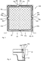
- FIG. 1 illustrates an example of consumable rack 10.
- the consumable rack comprises an upper surface 11 comprising a plurality of consumable holding positions 12 for holding consumables, e.g. reaction vessels (not shown).
- the consumable rack 10 has a substantially squared shape with the upper surface 11 having a substantially squared shape.
- the consumable rack 10 further comprises four rack sidewalls 13a, 13b, 13c, 13d on respective sides of the rack 10, extending externally downwards from the upper surface 11 and having substantially equal height and length.
- the four rack sidewalls 13a, 13b, 13c, 13d are joined to each other by four side edges 14a, 14b, 14c, 14d diagonally arranged relative to the upper surface 11 such as to form a continuous perimeter wall around the rack 10.
- the edges 14a, 14b, 14c, 14d have at least partially a blunt face 15a, 15b, 15c, 15d.
- the rack sidewalls 13a, 13b, 13c, 13d each comprise a rack alignment element 16a, 16b, 16c, 16d substantially aligned with the center 17 of the upper surface 11 and therefore centrally located with respect to the respective sidewalls 13a, 13b, 13c, 13d.
- the rack alignment elements 16a, 16b, 16c, 16d are abutment elements comprising contact faces 18a, 18b, 18c, 18d respectively.
- the entire consumable rack 10 may be made of one piece, e.g. using a polymeric material, e.g. by an injection molding process.
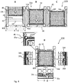
- FIG. 2 is a top view of the consumable rack 10 of FIG. 1 positioned in a rack receiving compartment 20 of a rack positioning system 100 (parts removes for clarity).
- the rack receiving compartment 20 is a three-dimensional space configured to receive one consumable rack 10 at a time and to hold a consumable rack 10 in a fixed and steady position within such three-dimensional space.
- the rack receiving compartment 20 comprises a fixedly mounted chassis 30 of substantially rectangular shape, comprising a front side 33a, a rear side 33c and two lateral sides 33b, 33d.
- the rack receiving compartment 20 further comprises a rack holding structure 40 (better illustrated in connection to FIG. 4-7 ) movably coupled to the chassis 30 such as to be movable between at least a first position and a second position relative to the chassis 30 (see FIG. 4 and FIG. 7 ).
- the chassis 30 comprises three chassis alignment elements 36b, 36c, 36d, each arranged at a fixed position of the rear side 33c and each of the two lateral sides 33b, 33d respectively.
- the chassis alignment elements 36b, 36c, 36d are abutment elements comprising contact faces 38b, 38c, 38d matching the contact faces 18b, 18c, 18d of the rack alignment elements 16b, 16c, 16d respectively and act as fixed references for positioning of the consumable rack 10.
- the rack holding structure 40 comprises a rack push element 45 arranged at a corner between the chassis front side 33a and a chassis lateral side 33b such as to push against the side edge 14a and particularly against edge face 15a of the rack 10 between two rack sidewalls 13a, 13b forcing each of three rack alignment elements 16b, 16c, 16d against a respective chassis alignment element 36b, 36c, 36d and laterally holding the consumable rack 10 in a fixed position delimited by the three chassis alignment elements 36b, 36c, 36d.
- the chassis alignment elements 36b, 36c, 36d are arranged with respect to the respective chassis side 33b, 33c, 33d such as to match the position of the rack alignment elements 16b, 16c, 16d when the rack holding structure 40 is moved from the first position towards the second position, and the rack push element 45 pushes the consumable rack 10.
- the consumable rack 10 comprises four rack alignment elements 16a, 16b, 16c, 16d
- only three rack alignment elements 16b, 16c, 16d are needed for positioning.
- the symmetrical and squared shape of the consumable rack allows however for the consumable rack 10 to be inserted into the rack receiving compartment 20 in any orientation. Therefore all four rack alignment elements 16a, 16b, 16c, 16d are equivalent and any three of them can be used.
- any of the side edges 14a, 14b, 14c, 14d with their blunt faces 15a, 15b, 15c, 15d can be oriented towards the rack push element 45, thereby obtaining an equivalent relationship.
- FIG. 3 which is a partial side view of the same embodiment of FIG. 2
- the contact faces 18a, 18b, 18c, 18d of the rack alignment elements 16a, 16b, 16c, 16d and the contact faces 38b, 38c, 38d of the chassis alignment elements 36b, 36c, 36d have a different extension in the vertical direction respectively, such as to allow a positioning tolerance in the vertical direction.
- FIG. 3 shows only one rack alignment element 16b and respective contact face 18b of the consumable rack 10 and only one chassis alignment element 36b and respective contact face 38b of the chassis 30 for simplicity.
- FIG. 4 illustrates an example of the process for inserting and positioning a consumable rack 10 into a rack receiving compartment 20 of a rack positioning system 100.
- the rack holding structure 40 further comprises a pair of base plates 43b, 43d movable relative to each other between different positions corresponding to different distances between the base plates 43b, 43d (see also FIG. 7 ).
- the base plates 43b, 43d are movable from an intermediate position X corresponding to the first position of the rack holding structure 40 (step A, B and C in FIG. 4 ), to a closed position X- ⁇ (X minus ⁇ ) corresponding to the second position of the rack holding structure 40 (step D in FIG. 4 ) where the base plates 43b, 43d are closer to each other.
- a consumable rack 10 can rest with the bottom of two opposite rack sidewalls 13b, 13d on respective base plates 43b, 43d.
- a consumable rack 10 is first inserted in the rack receiving compartment 20 by sliding the consumable rack 10 with the bottom of the rack sidewalls 13b, 13d on the base plates 43b, 43d respectively through the front side 33a of the chassis 30, until it reaches the rear front side 33c of the chassis 30.
- the rack push element 45 is fixed to one of the base plates 43b such as to move together with the base plate 43b.
- step D of FIG. 4 the base plates 43b, 43d are moved towards each other from the intermediate position X to the closed position X - ⁇ .
- the rack push element 45 pushes against the side edge face 15a of the consumable rack 10 forcing each of three rack alignment elements 16b, 16c, 16d against the respective chassis alignment element 36b, 36c, 36d and laterally holding the consumable rack 10 in a fixed position delimited by the three chassis alignment elements 36b, 36c, 36d.
- the location and design of the rack push element 45 are chosen so that the direction of the resulting push force applied against the side edge face 15a has a particular angle ⁇ , the effect of which is explained in connection to FIG. 8 and FIG. 9 .
- Movement of the base plates 43b, 43d is controlled by a motorized spindle drive 44.
- the base plates 43b, 43d can be moved to an open position X+ ⁇ (X plus ⁇ ) corresponding to a third position of the rack holding structure 40 wherein the base plates 43b, 43d are farther from each other and a consumable rack 10 is prevented from resting on the base plates 43b, 43d.
- X+ ⁇ it is possible to remove a consumable rack 10 from the rack receiving compartment 20 through a bottom side of the chassis 30 or to insert a consumable rack 10 through the bottom side of the chassis 30.
- FIG. 5 illustrates a consumable rack 10' positioned in a rack positioning system 100 (parts removed for clarity) seen from the front side 33a of the chassis 30.
- FIG. 6 illustrates the same consumable rack 10' of FIG. 5 in the same position as in FIG. 5 seen though the lateral side 33b of the chassis 30 (parts removed for clarity).
- elements of the chassis 30, comprising the rack alignment elements 36b, 36c, 36d and elements of the rack holding structure 40 comprising the base plates 43b, 43d and the rack push element 45 are shown.
- the rack push element 45 is fixed to one of the base plates 43b such as to be movable together with the base plate 43b and comprises a ball bearing 46 for reducing friction by rolling against the blunt face 15a of side edge 14a of the consumable rack 10'.
- the rack push element 45 further comprise a resilient body 47 in order to prevent overloading or underloading the rack push element 45 and therefore allowing a certain tolerance in the amount and direction of the applied force when the rack holding structure 40 is moved from the first position to the second position (see FIG. 7 ).
- the consumable rack 10' is identical to the consumable rack 10 of FIG. 1 to FIG. 4 , with the exception that the rack sidewalls have slight different design but identical function.
- FIG. 7 illustrates different positions that can be assumed by the rack holding structure 40.
- the base plates 43b, 43d are movable towards and away from each other thereby assuming different positions corresponding to different distances between the base plates 43b, 43d.
- the base plates 43b, 43d are movable from an intermediate position X corresponding to the first position of the rack holding structure 40, to a closed position X- ⁇ (X minus ⁇ ), corresponding to the second position of the rack holding structure 40, where the base plates 43b, 43d are closer to each other and where ⁇ (delta) is the difference in distance between the two positions.
- a consumable rack 10' can rest on the respective base plates 43b, 43d.
- the rack 10' can be inserted or removed through the front side of the chassis 30.
- the rack 10' is positioned by the force applied by the rack push element 45 that moves together with the base plate 43b.
- the base plates 43b, 43d can be also moved from the closed position X - ⁇ back to the intermediate position X or to an open position X+ ⁇ (X plus ⁇ ) corresponding to a third position of the rack holding structure 40 wherein the base plates 43b, 43d are farther from each other and a consumable rack 10' is prevented from resting on the base plates 43b, 43d.
- X+ ⁇ it is for example possible to remove a consumable rack 10' through a bottom side of the chassis 30 or to insert a consumable rack 10' through the bottom side of the chassis 30.
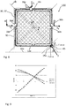
- FIG. 8 and FIG. 9 illustrate the forces involved when positioning a consumable rack 10, 10' in a rack positioning system 100 and how they change as a function of the direction of the force applied by the rack push element 45.
- the estimated coefficient of friction according to Roloff-Matek is about 0.3 or in a range comprised between 0.25 and 0.4.
- the graph of FIG. 9 plots how the distribution of forces D, C and B in Newton (N) varies by varying the angle ⁇ , while taking into account the friction forces R D , R B and R C and a friction coefficient of 0.3. It can be seen that a substantial equilibrium of forces for D, B, and C can be obtained at an angle ⁇ of about 57°.
- the angle ⁇ at which a substantial equilibrium of forces for B, C and D can be obtained is about 63-64° (not shown).
- One way of fixing the angle ⁇ at a selected value, e.g. 57° is to design the rack 10, 10' and in particular the side edge face 15a at a corresponding orientation with respect to the rack push element 45.
- the side edge face 15a is oriented at an angle ⁇ that is different from 90° with respect to the rack diagonal ab.
- the side edge face 15a is asymmetrical with respect to this diagonal line, i.e. more extended (inclined) towards the front sidewall 13a and less towards the lateral sidewall 13b.
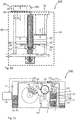
- FIG. 10 illustrates other components of a rack positioning system 100 according to an embodiment.
- the rack positioning system 100 further comprises a front movable loading structure 50 configured for inserting a consumable rack 10" carrying consumables 1 into the rack receiving compartment 20 through the chassis front side 33a when the rack holding structure 40 is in the first position and a bottom movable unloading structure 60 for taking an empty rack 10" out of the rack receiving compartment 20 through a chassis bottom side 34 when the rack holding structure 40 is in the third position.
- the front movable loading structure 50 and the bottom movable unloading structure 60 both comprise a lift mechanism 51, 61 that can move stepwise upwards and downwards respectively in order to lift a stack 19, 19' of racks 10" and handing over to and taking over from the rack receiving compartment 20 one rack 10" at a time respectively.
- the front movable loading structure 50 further comprises a separating device 52, cooperating with the lift mechanism 51, for separating a rack 10" at a time from a stack 19 of racks and handing over the rack 10" to the rack receiving compartment 20 through the chassis front side 33a when the rack holding structure 40 is in the first position.
- a suitable separating device is e.g. disclosed in US7360984B1 and not further elucidated here.
- the consumable rack 10" once used may be taken out of the rack receiving compartment 20 through a chassis bottom side 34 when the rack holding structure 40 is in the third position.
- the lift mechanism 61 may be raised until nearly reaching the bottom of the rack 10" in the rack receiving compartment 20 and the rack 10" may be added on top of an eventual stack 19' of racks 10" already present in the unloading structure 60 until there is space for other racks 10".
- the lift mechanism 61 moves thus a step at a time lower corresponding top the height of a rack 10" until it reaches the lowest position, after which the entire stack 19' of used racks 10" can be taken out of the unloading structure 60 and the process can be repeated by building up a new stack 19'.
- new consumables racks 10" can be inserted as a stack 19 of a predetermined number of consumable racks 10" fitting on the lift mechanism 51 when it is in the lowest position and then the lift mechanism 51 can move one step at a time upwards corresponding to the height of a rack 10".
- any number of racks 10" can be added or removed at any time form a respective stack 19, 19'.
- the consumable rack 10" is similar to the consumable racks 10, 10' of FIG. 1 to FIG. 8 , with the exception that the rack sidewalls have different design but identical function.
- FIG. 11 illustrates an example of automated in vitro diagnostic system 200 comprising the rack positioning system 100.
- the automated in vitro diagnostic system 100 further comprises a consumable manipulator 221 configured to cooperate with the rack positioning system 100 to manipulate a particular piece of consumable 1 in a rack 10, 10', 10" in a particular consumable holding position 12.
- the consumables 1 are reaction vessels used for receiving an aliquot of a sample and one or more reagents for a reaction to take place before detection.
- the in vitro diagnostic system 200 comprises a sample loading unit 211 for loading sample racks 210 carrying sample tubes 201.
- the sample racks can be transported to an aspiration position 212 where a sample pipetting unit 232 is located for aspirating an aliquot of sample from a sample tube 201, before moving further to an unloading unit 213.
- the in vitro diagnostic system 200 further comprises a reagent compartment 240 comprising reagent containers 241 and a reagent pipetting unit 242 for aspirating reagents from the reagent containers 241.
- the in vitro diagnostic system 200 further comprises an incubation station 250 comprising a plurality of reaction vessel holding positions 251, where reaction mixtures of samples and reagents added to reaction vessels 1 can be incubated before being aspirated by a third pipetting unit 252 and subjected to analysis by detector 260.
- the consumable manipulator 221 is in this case configured as a gripper for gripping and moving reaction vessels 1 within a predefined range of movement in a three-dimensional space, including a space above the rack receiving compartment 20, part of the space above the incubation station 250 and the space above a sample dispensing position 233 and reaction vessel disposing position 234.
- the consumable manipulator 221 is configured to move in a plane along a first translation guide 222 and an orthogonal translation guide 223 and in addition in a vertical direction thereby enabling random access to any of the consumables 1 in the consumable rack 10, 10', 10".
- the consumable manipulator 221 is controlled by controller 270 to execute operations in connection to the use of the consumables 1 by the in vitro diagnostic system 200.
- the consumable manipulator grips a reaction vessel 1 from one of the consumable holding positions 12 of a rack 10, 10, 10" positioned in the rack receiving compartment 20 of the rack positioning system 100 and places the reaction vessel 1 in the sample dispensing position 233.
- an aliquot of sample is added by the sample pipetting unit 232.
- the consumable manipulator 221 grips again and moves the reaction vessel 1 to one of the reaction vessel holding positions 251 of the incubation station 250.
- the consumable manipulator 221 grips the used reaction vessel 1 from the incubation station 250 and transports it to the disposing position 234 where it is disposed.
Claims (15)
- Système de positionnement de portoir (100) pour positionner un portoir de consommables (10, 10', 10") dans un système automatisé de diagnostic in vitro (200), le système de positionnement de portoir (100) comprenant :- un portoir de consommables (10, 10', 10") comprenant une surface supérieure (11), la surface supérieure (11) comprenant une pluralité de positions de support de consommables ,- un compartiment de réception de portoir (20) comprenant un châssis (30) monté de manière fixe de forme pratiquement rectangulaire, comprenant un côté avant (33a), un côté arrière (33c) et deux côtés latéraux (33b, 33c), le compartiment de réception de portoir (20) comprenant en outre une structure de maintien de portoir (40) couplée de manière mobile au châssis (30) de sorte à être mobile entre au moins une première position (X) et une deuxième position (X-Δ) par rapport au châssis (30),dans lequel
le portoir de consommables (10, 10', 10") a une forme pratiquement carrée dont la surface supérieure (11) a une forme pratiquement carrée et un centre (17), le portoir de consommables (10, 10', 10") comprenant en outre des parois latérales (13a, 13b, 13c, 13d) sur les côtés respectifs du portoir (10, 10', 10"),
caractérisé en ce que
au moins trois parois latérales (13a, 13b, 13c, 13d) du portoir comprennent chacune un élément d'alignement de portoir (16a, 16b, 16c, 16d) pratiquement aligné avec le centre (17) de la surface supérieure (11) et ainsi situé de manière centrale par rapport aux parois latérales (13a, 13b, 13c, 13d) respectives,
dans lequel le châssis (30) comprend trois éléments d'alignement de châssis (36b, 36c, 36d), chacun étant disposé au niveau d'une position fixe du côté arrière (33c) et de chacun des deux côtés latéraux (33b, 33d) respectivement,
et dans lequel la structure de maintien de portoir de consommables (40) comprend un élément de poussée de portoir (45) disposé au niveau d'un coin entre le côté avant (33a) du châssis et un côté latéral (33b) du châssis de sorte à s'appuyer contre un bord latéral (14a) du portoir (10, 10', 10") entre deux parois latérales (13a, 13b) du portoir lorsque la structure de maintien de portoir (40) est déplacée de la première position (X) vers la deuxième position (X-Δ), forçant ainsi chacun des trois éléments d'alignement de portoir (16b, 16c, 16d) contre un élément d'alignement de châssis (36b, 36c, 36d) respectif et maintenant latéralement le portoir de consommables (10, 10', 10") dans une position fixe délimitée par les trois éléments d'alignement de châssis (36b, 36c, 36d). - Système de positionnement de portoir (100) selon la revendication 1 dans lequel les éléments d'alignement de portoirs (16a, 16b, 16c, 16d) et les éléments d'alignement de châssis (36b, 36c, 36d) sont des éléments de butée comprenant des faces de contact (18b, 18c, 18d, 38b, 38c, 38d) correspondant les unes avec les autres.
- Système de positionnement de portoir (100) selon la revendication 2 dans lequel les faces de contact des éléments d'alignement de portoirs (18b, 18c, 18d) et les faces de contact des éléments d'alignement de châssis (38b, 38c, 38d) présentent respectivement une extension différente dans la direction verticale, de sorte à permettre une tolérance de positionnement dans la direction verticale.
- Système de positionnement de portoir (100) selon la revendication 2 ou 3 dans lequel l'élément de poussée de portoir (45) est disposé de sorte à appliquer une force sur le bord latéral (14a) à un angle (a) différent par rapport à un angle de 45 degrés d'une ligne diagonale (ab) du portoir traversant le bord latéral (14a), de sorte à obtenir un équilibre substantiel des forces latérales.
- Système de positionnement de portoir (100) selon la revendication 4 dans lequel l'angle (a) est un angle compris entre 50 et 70 degrés par rapport à une ligne horizontale parallèle à la paroi latérale (13a) du portoir faisant face au côté avant (33a) du châssis.
- Système de positionnement de portoir (100) selon la revendication 5 dans lequel l'angle est d'environ 57 degrés, de sorte à prendre en compte les forces de frottement agissant sur les faces de contact (18b, 18c, 18d, 38b, 38c, 38d).
- Système de positionnement de portoir (100) selon l'une quelconque des revendications précédentes dans lequel la structure de maintien de portoir (40) comprend en outre une paire de plaques de base (43b, 43d) mobiles l'une par rapport à l'autre entre différentes positions (X, X-Δ, X+Δ) correspondant à différentes distances entre les plaques de base (43b, 43d).
- Système de positionnement de portoir (100) selon la revendication 7 dans lequel les plaques de base (43b, 43d) sont mobiles d'une position intermédiaire (X) correspondant à la première position de la structure de maintien de portoir (40), qui permet à un portoir de consommables (10, 10', 10")s de reposer avec au moins une partie d'un fond sur les plaques de base (43b, 43d), vers une position fermée (X-Δ) correspondant à la deuxième position de la structure de maintien de portoir (40) dans laquelle les plaques de base (43b, 43d) sont plus proches l'une de l'autre et un portoir de consommables (10, 10', 10") peut encore reposer avec le fond sur les plaques de base (43b, 43d), et vers une position ouverte (X+Δ) correspondant à une troisième position de la structure de maintien de portoir (40) dans laquelle les plaques de base (43b, 43d) sont plus éloignées l'une de l'autre et un portoir de consommables (10, 10', 10") ne peut pas reposer sur les plaques de base (43b, 43d).
- Système de positionnement de portoir (100) selon l'une quelconque des revendications précédentes comprenant en outre au moins une structure de chargement (50) et/ou de déchargement (60) mobile pour charger et/ou décharger un portoir de consommables (10, 10', 10") dans le compartiment de réception de portoir (20).
- Système de positionnement de portoir (100) selon la revendication 9 dans lequel l'au moins une structure de chargement (50) et/ou de déchargement mobile est configurée pour insérer un portoir de consommables (10, 10', 10") ou retirer un portoir de consommables (10, 10', 10") du compartiment de réception de portoir (20) par le côté avant (33a) du châssis (30) lorsque la structure de maintien de portoir (40) se trouve dans la première position (X).
- Système de positionnement de portoir (100) selon la revendication 9 dans lequel l'au moins une structure de chargement et/ou de déchargement (60) mobile est configurée pour insérer un portoir de consommables (10, 10', 10") ou retirer un portoir de consommables (10, 10', 10") du compartiment de réception de portoir par un côté inférieur du châssis (30) lorsque la structure de maintien de portoir (40) se trouve dans la troisième position (X+Δ).
- Système de positionnement de portoir (100) selon l'une quelconque des revendications 9 à 11 comprenant une structure de chargement (50) mobile avant pour insérer un portoir de consommables (10, 10', 10") dans le compartiment de réception de portoir (20) par le côté avant (33a) du châssis (30) et une structure de déchargement (60) mobile inférieure pour retirer un portoir de consommables (10, 10', 10") du compartiment de réception de portoir (20) par le côté inférieur du châssis (30) ou une structure de chargement mobile inférieure pour insérer un portoir de consommables (10, 10', 10") dans le compartiment de réception de portoir (20) par le côté inférieur du châssis (30) et une structure de déchargement mobile avant pour retirer un portoir de consommables (10, 10', 10") du compartiment de réception de portoir (20) par le côté avant (33a) du châssis (30).
- Système de positionnement de portoir (100) selon l'une quelconque des revendications 9 à 12 dans lequel l'au moins une structure de chargement (50) et/ou de déchargement (60) mobile comprend un mécanisme de levage (51, 61) pour lever et/ou baisser une pile (19, 19') de portoirs (10, 10', 10") de consommables et transférer vers et/ou reprendre du compartiment de réception de portoir (20) un portoir de consommables (10, 10', 10") à la fois.
- Système automatisé de diagnostic in vitro (200) comprenant le système de positionnement de portoir (100) selon l'une quelconque des revendications 1 à 13.
- Système automatisé de diagnostic in vitro (200) selon la revendication 14, comprenant en outre un manipulateur de consommables (221) configuré pour coopérer avec le système de positionnement de portoir (100) pour manipuler une pièce particulière de consommable (1) dans le portoir de consommables (10, 10', 10") dans une position de maintien de consommables (12) particulière.
Priority Applications (4)
| Application Number | Priority Date | Filing Date | Title |
|---|---|---|---|
| EP17190199.4A EP3454064B1 (fr) | 2017-09-08 | 2017-09-08 | Système de positionnement de portoir |
| US16/118,490 US11103872B2 (en) | 2017-09-08 | 2018-08-31 | Rack positioning system |
| CN201811039234.1A CN109465046B (zh) | 2017-09-08 | 2018-09-06 | 搁架定位系统 |
| JP2018168113A JP7000282B2 (ja) | 2017-09-08 | 2018-09-07 | ラック位置決めシステム |
Applications Claiming Priority (1)
| Application Number | Priority Date | Filing Date | Title |
|---|---|---|---|
| EP17190199.4A EP3454064B1 (fr) | 2017-09-08 | 2017-09-08 | Système de positionnement de portoir |
Publications (2)
| Publication Number | Publication Date |
|---|---|
| EP3454064A1 EP3454064A1 (fr) | 2019-03-13 |
| EP3454064B1 true EP3454064B1 (fr) | 2020-11-11 |
Family
ID=59846436
Family Applications (1)
| Application Number | Title | Priority Date | Filing Date |
|---|---|---|---|
| EP17190199.4A Active EP3454064B1 (fr) | 2017-09-08 | 2017-09-08 | Système de positionnement de portoir |
Country Status (4)
| Country | Link |
|---|---|
| US (1) | US11103872B2 (fr) |
| EP (1) | EP3454064B1 (fr) |
| JP (1) | JP7000282B2 (fr) |
| CN (1) | CN109465046B (fr) |
Families Citing this family (3)
| Publication number | Priority date | Publication date | Assignee | Title |
|---|---|---|---|---|
| USD900337S1 (en) * | 2018-12-06 | 2020-10-27 | Heathrow Scientific Llc | Tube rack |
| CN111942841B (zh) * | 2020-08-19 | 2021-11-30 | 宁波三韩合金材料有限公司 | 一种料盘自动上料系统及使用方法 |
| CN116761679A (zh) | 2021-01-26 | 2023-09-15 | 贝克顿迪金森法国公司 | 用于包装柱塞止挡件的具有夹持件的嵌套件,以确保若干嵌套件在盒体中可靠对准 |
Family Cites Families (24)
| Publication number | Priority date | Publication date | Assignee | Title |
|---|---|---|---|---|
| US6586255B1 (en) * | 1997-07-21 | 2003-07-01 | Quest Diagnostics Incorporated | Automated centrifuge loading device |
| FR2768066B1 (fr) * | 1997-09-08 | 1999-11-26 | Gilson Sa | Portoir pour cones de pipette multicanaux |
| US6323035B1 (en) * | 1997-09-24 | 2001-11-27 | Glaxo Wellcome, Inc. | Systems and methods for handling and manipulating multi-well plates |
| US6254826B1 (en) * | 1997-11-14 | 2001-07-03 | Gen-Probe Incorporated | Assay work station |
| JP4454904B2 (ja) * | 2000-03-15 | 2010-04-21 | 株式会社日立製作所 | 自動分析装置及びそれに用いる部品供給装置 |
| US6790413B2 (en) * | 2001-05-03 | 2004-09-14 | Beckman Coulter, Inc. | Sample presentation unit |
| AU2003256285A1 (en) * | 2002-06-28 | 2004-01-19 | Igen International, Inc. | Improved assay systems and components |
| US7275807B2 (en) * | 2002-11-27 | 2007-10-02 | Edc Biosystems, Inc. | Wave guide with isolated coupling interface |
| US8496875B2 (en) * | 2004-05-21 | 2013-07-30 | Caliper Life Sciences, Inc. | Automated system for handling microfluidic devices |
| EP2530025B1 (fr) * | 2008-07-25 | 2015-11-04 | F.Hoffmann-La Roche Ag | élément d' alignement pour portoirs de tubes d' échantillons |
| IT1390858B1 (it) * | 2008-08-05 | 2011-10-19 | Dachi S R L | "banco di carico e scarico di contenitori di materiale biologico in un impianto di automazione" |
| DE102009013778B4 (de) * | 2009-03-18 | 2013-08-14 | Quantifoil Instruments Gmbh | Positioniereinrichtung für einen Probenträger |
| DE102010011899B4 (de) * | 2010-03-18 | 2013-11-21 | Quantifoil Instruments Gmbh | Positioniereinrichtung für eine Funktionseinrichtung |
| EP2749887A3 (fr) * | 2010-07-23 | 2014-10-01 | Beckman Coulter, Inc. | Système ou procédé comprenant des unités analytiques |
| EP2538225A1 (fr) * | 2011-06-20 | 2012-12-26 | F. Hoffmann-La Roche AG | Système de traitement de tubes d'échantillons fermés |
| CN202246010U (zh) * | 2011-08-11 | 2012-05-30 | 无锡市德瑞包装设备制造有限公司 | 一种容器定位移位装置 |
| US20130108522A1 (en) * | 2011-10-27 | 2013-05-02 | Molecular Bioproducts, Inc. | Self Locking Snap Plate |
| CN202748367U (zh) * | 2012-08-10 | 2013-02-20 | 深圳德夏科技发展有限公司 | 温育架定位结构 |
| CN103399161B (zh) * | 2013-07-17 | 2014-11-05 | 深圳市新产业生物医学工程股份有限公司 | 一种便捷式全自动化学发光免疫分析系统及其分析方法 |
| EP3006110A1 (fr) * | 2014-10-10 | 2016-04-13 | F.Hoffmann-La Roche Ag | Grille |
| CN104436753B (zh) * | 2014-12-09 | 2016-05-25 | 天津博纳艾杰尔科技有限公司 | 一种固相萃取仪 |
| JP2017040511A (ja) * | 2015-08-18 | 2017-02-23 | 株式会社日立製作所 | ノズルチップ供給装置 |
| EP3139175B1 (fr) * | 2015-09-01 | 2021-12-15 | Roche Diagnostics GmbH | Système de distribution d'une cargaison de laboratoire, système d'automatisation de laboratoire et procédé de fonctionnement d'un système de distribution de cargaison de laboratoire |
| CN105259357A (zh) * | 2015-11-09 | 2016-01-20 | 苏州怡创医疗器械有限公司 | 一种全自动化学发光测定仪 |
-
2017
- 2017-09-08 EP EP17190199.4A patent/EP3454064B1/fr active Active
-
2018
- 2018-08-31 US US16/118,490 patent/US11103872B2/en active Active
- 2018-09-06 CN CN201811039234.1A patent/CN109465046B/zh active Active
- 2018-09-07 JP JP2018168113A patent/JP7000282B2/ja active Active
Non-Patent Citations (1)
| Title |
|---|
| None * |
Also Published As
| Publication number | Publication date |
|---|---|
| US11103872B2 (en) | 2021-08-31 |
| CN109465046A (zh) | 2019-03-15 |
| JP7000282B2 (ja) | 2022-01-19 |
| EP3454064A1 (fr) | 2019-03-13 |
| JP2019078744A (ja) | 2019-05-23 |
| CN109465046B (zh) | 2022-04-29 |
| US20190076848A1 (en) | 2019-03-14 |
Similar Documents
| Publication | Publication Date | Title |
|---|---|---|
| JP6514173B2 (ja) | マルチウェル・プレート及び蓋体 | |
| US11103872B2 (en) | Rack positioning system | |
| US6592324B2 (en) | Gripper mechanism | |
| EP3435091B1 (fr) | Dispositif d'analyse automatique | |
| EP3368465A1 (fr) | Échange d'embouts automatisé pour machines d'application et d'extraction de bouchons de tubes de prélèvement de laboratoire | |
| EP2333557B1 (fr) | Système d'identification de matériel consommable | |
| US20090202334A1 (en) | Method and system for transporting and storing multiple reagent packs and reagent packs used therein | |
| JP6034416B2 (ja) | 自動分析器において分析対象物を単離かつ分析する方法及び分析システム | |
| JP7387775B2 (ja) | チップを装填するためのモーションシステム | |
| JP2011123067A (ja) | 空間的分離による増幅システム | |
| JP2011123065A (ja) | 組み合わせ先端部用ラック | |
| CA2410090A1 (fr) | Support de precision automatique | |
| AU2001271317A1 (en) | Automated precision object holder | |
| US20050053454A1 (en) | Device and method for transferring objects | |
| JP2011185930A (ja) | 分析器のハードウェア構成 | |
| CN110573254B (zh) | 盖组件和相关的使用方法 | |
| US20190299415A1 (en) | Methods and apparatus to calibrate a positional orientation between a robot gripper and a component | |
| JP7463375B2 (ja) | 実験試料を自動処理するための自動実験システム | |
| CN114476664A (zh) | 上料机 | |
| JP5276189B2 (ja) | マイクロプレート用ピックアップ装置、及びマイクロプレート供給回収装置 | |
| CN220490845U (zh) | 自动化分析仪 | |
| EP3578485B1 (fr) | Système de distribution de récipient | |
| WO2023201055A1 (fr) | Système et appareil de préhension de plaques de traitement biologique |
Legal Events
| Date | Code | Title | Description |
|---|---|---|---|
| PUAI | Public reference made under article 153(3) epc to a published international application that has entered the european phase |
Free format text: ORIGINAL CODE: 0009012 |
|
| STAA | Information on the status of an ep patent application or granted ep patent |
Free format text: STATUS: THE APPLICATION HAS BEEN PUBLISHED |
|
| AK | Designated contracting states |
Kind code of ref document: A1 Designated state(s): AL AT BE BG CH CY CZ DE DK EE ES FI FR GB GR HR HU IE IS IT LI LT LU LV MC MK MT NL NO PL PT RO RS SE SI SK SM TR |
|
| AX | Request for extension of the european patent |
Extension state: BA ME |
|
| STAA | Information on the status of an ep patent application or granted ep patent |
Free format text: STATUS: REQUEST FOR EXAMINATION WAS MADE |
|
| 17P | Request for examination filed |
Effective date: 20190913 |
|
| RBV | Designated contracting states (corrected) |
Designated state(s): AL AT BE BG CH CY CZ DE DK EE ES FI FR GB GR HR HU IE IS IT LI LT LU LV MC MK MT NL NO PL PT RO RS SE SI SK SM TR |
|
| GRAP | Despatch of communication of intention to grant a patent |
Free format text: ORIGINAL CODE: EPIDOSNIGR1 |
|
| STAA | Information on the status of an ep patent application or granted ep patent |
Free format text: STATUS: GRANT OF PATENT IS INTENDED |
|
| RIC1 | Information provided on ipc code assigned before grant |
Ipc: G01N 35/10 20060101ALN20200527BHEP Ipc: G01N 35/04 20060101AFI20200527BHEP Ipc: B01L 9/00 20060101ALI20200527BHEP |
|
| INTG | Intention to grant announced |
Effective date: 20200617 |
|
| GRAS | Grant fee paid |
Free format text: ORIGINAL CODE: EPIDOSNIGR3 |
|
| GRAA | (expected) grant |
Free format text: ORIGINAL CODE: 0009210 |
|
| STAA | Information on the status of an ep patent application or granted ep patent |
Free format text: STATUS: THE PATENT HAS BEEN GRANTED |
|
| AK | Designated contracting states |
Kind code of ref document: B1 Designated state(s): AL AT BE BG CH CY CZ DE DK EE ES FI FR GB GR HR HU IE IS IT LI LT LU LV MC MK MT NL NO PL PT RO RS SE SI SK SM TR |
|
| REG | Reference to a national code |
Ref country code: GB Ref legal event code: FG4D |
|
| REG | Reference to a national code |
Ref country code: CH Ref legal event code: EP |
|
| REG | Reference to a national code |
Ref country code: AT Ref legal event code: REF Ref document number: 1333989 Country of ref document: AT Kind code of ref document: T Effective date: 20201115 |
|
| REG | Reference to a national code |
Ref country code: DE Ref legal event code: R096 Ref document number: 602017027267 Country of ref document: DE |
|
| REG | Reference to a national code |
Ref country code: IE Ref legal event code: FG4D |
|
| REG | Reference to a national code |
Ref country code: NL Ref legal event code: MP Effective date: 20201111 |
|
| REG | Reference to a national code |
Ref country code: AT Ref legal event code: MK05 Ref document number: 1333989 Country of ref document: AT Kind code of ref document: T Effective date: 20201111 |
|
| PG25 | Lapsed in a contracting state [announced via postgrant information from national office to epo] |
Ref country code: NO Free format text: LAPSE BECAUSE OF FAILURE TO SUBMIT A TRANSLATION OF THE DESCRIPTION OR TO PAY THE FEE WITHIN THE PRESCRIBED TIME-LIMIT Effective date: 20210211 Ref country code: RS Free format text: LAPSE BECAUSE OF FAILURE TO SUBMIT A TRANSLATION OF THE DESCRIPTION OR TO PAY THE FEE WITHIN THE PRESCRIBED TIME-LIMIT Effective date: 20201111 Ref country code: PT Free format text: LAPSE BECAUSE OF FAILURE TO SUBMIT A TRANSLATION OF THE DESCRIPTION OR TO PAY THE FEE WITHIN THE PRESCRIBED TIME-LIMIT Effective date: 20210311 Ref country code: GR Free format text: LAPSE BECAUSE OF FAILURE TO SUBMIT A TRANSLATION OF THE DESCRIPTION OR TO PAY THE FEE WITHIN THE PRESCRIBED TIME-LIMIT Effective date: 20210212 Ref country code: FI Free format text: LAPSE BECAUSE OF FAILURE TO SUBMIT A TRANSLATION OF THE DESCRIPTION OR TO PAY THE FEE WITHIN THE PRESCRIBED TIME-LIMIT Effective date: 20201111 |
|
| PG25 | Lapsed in a contracting state [announced via postgrant information from national office to epo] |
Ref country code: BG Free format text: LAPSE BECAUSE OF FAILURE TO SUBMIT A TRANSLATION OF THE DESCRIPTION OR TO PAY THE FEE WITHIN THE PRESCRIBED TIME-LIMIT Effective date: 20210211 Ref country code: PL Free format text: LAPSE BECAUSE OF FAILURE TO SUBMIT A TRANSLATION OF THE DESCRIPTION OR TO PAY THE FEE WITHIN THE PRESCRIBED TIME-LIMIT Effective date: 20201111 Ref country code: LV Free format text: LAPSE BECAUSE OF FAILURE TO SUBMIT A TRANSLATION OF THE DESCRIPTION OR TO PAY THE FEE WITHIN THE PRESCRIBED TIME-LIMIT Effective date: 20201111 Ref country code: IS Free format text: LAPSE BECAUSE OF FAILURE TO SUBMIT A TRANSLATION OF THE DESCRIPTION OR TO PAY THE FEE WITHIN THE PRESCRIBED TIME-LIMIT Effective date: 20210311 Ref country code: AT Free format text: LAPSE BECAUSE OF FAILURE TO SUBMIT A TRANSLATION OF THE DESCRIPTION OR TO PAY THE FEE WITHIN THE PRESCRIBED TIME-LIMIT Effective date: 20201111 Ref country code: SE Free format text: LAPSE BECAUSE OF FAILURE TO SUBMIT A TRANSLATION OF THE DESCRIPTION OR TO PAY THE FEE WITHIN THE PRESCRIBED TIME-LIMIT Effective date: 20201111 |
|
| REG | Reference to a national code |
Ref country code: LT Ref legal event code: MG9D |
|
| PG25 | Lapsed in a contracting state [announced via postgrant information from national office to epo] |
Ref country code: HR Free format text: LAPSE BECAUSE OF FAILURE TO SUBMIT A TRANSLATION OF THE DESCRIPTION OR TO PAY THE FEE WITHIN THE PRESCRIBED TIME-LIMIT Effective date: 20201111 |
|
| PG25 | Lapsed in a contracting state [announced via postgrant information from national office to epo] |
Ref country code: RO Free format text: LAPSE BECAUSE OF FAILURE TO SUBMIT A TRANSLATION OF THE DESCRIPTION OR TO PAY THE FEE WITHIN THE PRESCRIBED TIME-LIMIT Effective date: 20201111 Ref country code: SK Free format text: LAPSE BECAUSE OF FAILURE TO SUBMIT A TRANSLATION OF THE DESCRIPTION OR TO PAY THE FEE WITHIN THE PRESCRIBED TIME-LIMIT Effective date: 20201111 Ref country code: SM Free format text: LAPSE BECAUSE OF FAILURE TO SUBMIT A TRANSLATION OF THE DESCRIPTION OR TO PAY THE FEE WITHIN THE PRESCRIBED TIME-LIMIT Effective date: 20201111 Ref country code: LT Free format text: LAPSE BECAUSE OF FAILURE TO SUBMIT A TRANSLATION OF THE DESCRIPTION OR TO PAY THE FEE WITHIN THE PRESCRIBED TIME-LIMIT Effective date: 20201111 Ref country code: CZ Free format text: LAPSE BECAUSE OF FAILURE TO SUBMIT A TRANSLATION OF THE DESCRIPTION OR TO PAY THE FEE WITHIN THE PRESCRIBED TIME-LIMIT Effective date: 20201111 Ref country code: EE Free format text: LAPSE BECAUSE OF FAILURE TO SUBMIT A TRANSLATION OF THE DESCRIPTION OR TO PAY THE FEE WITHIN THE PRESCRIBED TIME-LIMIT Effective date: 20201111 |
|
| REG | Reference to a national code |
Ref country code: DE Ref legal event code: R097 Ref document number: 602017027267 Country of ref document: DE |
|
| PG25 | Lapsed in a contracting state [announced via postgrant information from national office to epo] |
Ref country code: DK Free format text: LAPSE BECAUSE OF FAILURE TO SUBMIT A TRANSLATION OF THE DESCRIPTION OR TO PAY THE FEE WITHIN THE PRESCRIBED TIME-LIMIT Effective date: 20201111 |
|
| PLBE | No opposition filed within time limit |
Free format text: ORIGINAL CODE: 0009261 |
|
| STAA | Information on the status of an ep patent application or granted ep patent |
Free format text: STATUS: NO OPPOSITION FILED WITHIN TIME LIMIT |
|
| 26N | No opposition filed |
Effective date: 20210812 |
|
| PG25 | Lapsed in a contracting state [announced via postgrant information from national office to epo] |
Ref country code: IT Free format text: LAPSE BECAUSE OF FAILURE TO SUBMIT A TRANSLATION OF THE DESCRIPTION OR TO PAY THE FEE WITHIN THE PRESCRIBED TIME-LIMIT Effective date: 20201111 Ref country code: AL Free format text: LAPSE BECAUSE OF FAILURE TO SUBMIT A TRANSLATION OF THE DESCRIPTION OR TO PAY THE FEE WITHIN THE PRESCRIBED TIME-LIMIT Effective date: 20201111 Ref country code: NL Free format text: LAPSE BECAUSE OF FAILURE TO SUBMIT A TRANSLATION OF THE DESCRIPTION OR TO PAY THE FEE WITHIN THE PRESCRIBED TIME-LIMIT Effective date: 20201111 |
|
| PG25 | Lapsed in a contracting state [announced via postgrant information from national office to epo] |
Ref country code: SI Free format text: LAPSE BECAUSE OF FAILURE TO SUBMIT A TRANSLATION OF THE DESCRIPTION OR TO PAY THE FEE WITHIN THE PRESCRIBED TIME-LIMIT Effective date: 20201111 |
|
| PG25 | Lapsed in a contracting state [announced via postgrant information from national office to epo] |
Ref country code: ES Free format text: LAPSE BECAUSE OF FAILURE TO SUBMIT A TRANSLATION OF THE DESCRIPTION OR TO PAY THE FEE WITHIN THE PRESCRIBED TIME-LIMIT Effective date: 20201111 |
|
| REG | Reference to a national code |
Ref country code: CH Ref legal event code: PL |
|
| REG | Reference to a national code |
Ref country code: BE Ref legal event code: MM Effective date: 20210930 |
|
| PG25 | Lapsed in a contracting state [announced via postgrant information from national office to epo] |
Ref country code: IS Free format text: LAPSE BECAUSE OF FAILURE TO SUBMIT A TRANSLATION OF THE DESCRIPTION OR TO PAY THE FEE WITHIN THE PRESCRIBED TIME-LIMIT Effective date: 20210311 Ref country code: MC Free format text: LAPSE BECAUSE OF FAILURE TO SUBMIT A TRANSLATION OF THE DESCRIPTION OR TO PAY THE FEE WITHIN THE PRESCRIBED TIME-LIMIT Effective date: 20201111 |
|
| PG25 | Lapsed in a contracting state [announced via postgrant information from national office to epo] |
Ref country code: LU Free format text: LAPSE BECAUSE OF NON-PAYMENT OF DUE FEES Effective date: 20210908 Ref country code: IE Free format text: LAPSE BECAUSE OF NON-PAYMENT OF DUE FEES Effective date: 20210908 Ref country code: BE Free format text: LAPSE BECAUSE OF NON-PAYMENT OF DUE FEES Effective date: 20210930 |
|
| PG25 | Lapsed in a contracting state [announced via postgrant information from national office to epo] |
Ref country code: LI Free format text: LAPSE BECAUSE OF NON-PAYMENT OF DUE FEES Effective date: 20210930 Ref country code: CH Free format text: LAPSE BECAUSE OF NON-PAYMENT OF DUE FEES Effective date: 20210930 |
|
| PG25 | Lapsed in a contracting state [announced via postgrant information from national office to epo] |
Ref country code: CY Free format text: LAPSE BECAUSE OF FAILURE TO SUBMIT A TRANSLATION OF THE DESCRIPTION OR TO PAY THE FEE WITHIN THE PRESCRIBED TIME-LIMIT Effective date: 20201111 |
|
| PG25 | Lapsed in a contracting state [announced via postgrant information from national office to epo] |
Ref country code: HU Free format text: LAPSE BECAUSE OF FAILURE TO SUBMIT A TRANSLATION OF THE DESCRIPTION OR TO PAY THE FEE WITHIN THE PRESCRIBED TIME-LIMIT; INVALID AB INITIO Effective date: 20170908 |
|
| PGFP | Annual fee paid to national office [announced via postgrant information from national office to epo] |
Ref country code: GB Payment date: 20230823 Year of fee payment: 7 |
|
| PGFP | Annual fee paid to national office [announced via postgrant information from national office to epo] |
Ref country code: FR Payment date: 20230822 Year of fee payment: 7 Ref country code: DE Payment date: 20230822 Year of fee payment: 7 |