EP3006110A1 - Grille - Google Patents
Grille Download PDFInfo
- Publication number
- EP3006110A1 EP3006110A1 EP14188485.8A EP14188485A EP3006110A1 EP 3006110 A1 EP3006110 A1 EP 3006110A1 EP 14188485 A EP14188485 A EP 14188485A EP 3006110 A1 EP3006110 A1 EP 3006110A1
- Authority
- EP
- European Patent Office
- Prior art keywords
- rack
- assay
- racks
- peripheral skirt
- surface plate
- Prior art date
- Legal status (The legal status is an assumption and is not a legal conclusion. Google has not performed a legal analysis and makes no representation as to the accuracy of the status listed.)
- Withdrawn
Links
Images


Classifications
-
- B—PERFORMING OPERATIONS; TRANSPORTING
- B01—PHYSICAL OR CHEMICAL PROCESSES OR APPARATUS IN GENERAL
- B01L—CHEMICAL OR PHYSICAL LABORATORY APPARATUS FOR GENERAL USE
- B01L9/00—Supporting devices; Holding devices
- B01L9/54—Supports specially adapted for pipettes and burettes
- B01L9/543—Supports specially adapted for pipettes and burettes for disposable pipette tips, e.g. racks or cassettes
-
- B—PERFORMING OPERATIONS; TRANSPORTING
- B01—PHYSICAL OR CHEMICAL PROCESSES OR APPARATUS IN GENERAL
- B01L—CHEMICAL OR PHYSICAL LABORATORY APPARATUS FOR GENERAL USE
- B01L2200/00—Solutions for specific problems relating to chemical or physical laboratory apparatus
- B01L2200/02—Adapting objects or devices to another
- B01L2200/025—Align devices or objects to ensure defined positions relative to each other
-
- B—PERFORMING OPERATIONS; TRANSPORTING
- B01—PHYSICAL OR CHEMICAL PROCESSES OR APPARATUS IN GENERAL
- B01L—CHEMICAL OR PHYSICAL LABORATORY APPARATUS FOR GENERAL USE
- B01L2300/00—Additional constructional details
- B01L2300/08—Geometry, shape and general structure
- B01L2300/0809—Geometry, shape and general structure rectangular shaped
-
- B—PERFORMING OPERATIONS; TRANSPORTING
- B01—PHYSICAL OR CHEMICAL PROCESSES OR APPARATUS IN GENERAL
- B01L—CHEMICAL OR PHYSICAL LABORATORY APPARATUS FOR GENERAL USE
- B01L2300/00—Additional constructional details
- B01L2300/08—Geometry, shape and general structure
- B01L2300/0848—Specific forms of parts of containers
- B01L2300/0858—Side walls
Definitions
- the present invention belongs to the field of processing fluid biological samples for analytical purposes. Within that field, the invention relates to a rack for holding assay tips and/or assay cups, in particular for use in analytical systems.
- Automated liquid handling devices are commonly used in such processes. Devices are commercially available which may include an automated pipetting head assembly movable within the device so that it may be aligned with test tubes or vials for reagent liquid handling.
- a pipette head assembly uses disposable assay tips to aspirate and release samples and reagents.
- Such assay tips are usually provided in a rack (such as shown in figure 1 ) comprising assay tip through boreholes having seating areas for removably receiving the assay tips.
- racks may also comprise assay cup through boreholes having seating areas for removably receiving the assay cups used as reaction vessels.
- Racks are commonly supplied and/or stored in (pre-configured) stacks of racks (such as shown in figure 3 ). Each rack is pre-loaded with a defined number of assay tips 100 and optionally, assay cups 200. To reduce the height of the stack of racks, and, hence, the space needed to store the assay tips, the racks are configured to nest when they are stacked, that is with the assay tips in each rack nesting in the assay tips in the rack below. Therefore, on one hand, the racks nest in the sense that a lower part of an upper rack accommodates an upper part of a lower rack on which the upper rack is stacked. On the other hand, the assay tips nest in the sense that a part of a pointed portion of an assay tip in the upper rack is located inside a neck portion of an assay tip in the corresponding location in the lower rack.
- prior art racks 10 - such as shown in figures 1 to 3 - comprise guiding element(s) - in the form of slits 50 and corresponding rails 60 - arranged in the center of a side wall of the peripheral skirt 70 of the prior art racks 10.
- guiding element(s) force the racks 10, 10' into alignment as they are stacked.
- the racks 10, 10' are forced into alignment when a guiding length G L0 is reached.
- the racks 10, 10' must be configured such that in view of the size and shape of the assay tips 100 - in particular the inner diameter of their neck portion - the pointed portion of the assay tips 100 held in the upper rack 10 only reach the neck portion of the assay tips held in the lower rack 10' after the racks have been sufficiently aligned. Therefore there must be a direct correlation between the assay tips and the racks. Thus a compromise must be made between the height of the racks and the alignment provided by the guiding elements.
- Embodiments of the disclosed rack therefore aim to provide improved stacking capability while ensuring that assay tip collision is avoided despite possible misalignment as the racks are being stacked.
- the disclosed rack is based on the recognition that, before the centrally arranged guiding elements of prior art racks start to engage and thus align the prior art racks, a too high of a misaligned stacking depth M SD0 is already reached, especially in areas around the edges/ and corners of the prior art racks 10 - such as is illustrated in figure 2 .
- the guiding elements of the disclosed racks are arranged near the edges of the side walls of the the peripheral skirt. Additionally, in order to provide an alignment of the racks for both positive and negative vertical misalignment angles, a pair of guiding elements is arranged along opposing edges of the side wall(s). Furthermore, in order to provide an alignment of vertical misalignment in both the Z-Y and Z-X planes of the three-dimensional Cartesian coordinate system, four guiding elements of the disclosed racks are arranged near opposing edges of two substantially orthogonal side walls of the peripheral skirt.
- the disclosed rack includes: a surface plate, the surface plate comprising assay tip through boreholes extending substantially in a Z direction orthogonal to the surface plate, the assay tip through boreholes having seating areas for receiving assay tips in the rack; a peripheral skirt extending from a periphery of the surface plate substantially in the Z direction; and at least four guiding elements extending substantially in the Z direction, a first pair of the four guiding elements being respectively arranged near opposing edges of a first side wall of the peripheral skirt and a second pair of the four guiding elements being respectively arranged near opposing edges of a second side wall of the peripheral skirt, substantially orthogonal to the first side wall, wherein each guiding element comprises a slit and a corresponding rail, the guiding elements being arranged such that the rail of the rack is guided into a corresponding slit of a similar rack thereby aligning the rack and a similar rack and such that assay tips received in the
- Embodiments of the disclosed rack are particularly advantageous as an early guidance during a stacking process is provided in two dimensions, thereby avoiding increase of or even allowing a reduction of the stacking height despite increased assay tip density and/or increased rack size and/or decreased assay tip dimensions, such as in particular, a decrease in assay tip diameter.
- further embodiments of the disclosed rack comprise guiding elements configured to provide both vertical and horizontal alignment of the racks.
- an increased guiding length of the guiding elements may be provided such that the rack height is defined as the sum of the assay tip height and the guiding length.
- the guiding length may be increased - thereby improving alignment - without affecting the stacking height of the racks.
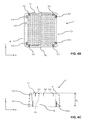
- Figures 4A to 4C show various views of a rack 1 for holding assay tips 100 according to the disclosed invention.
- the surface plate 3 is arranged on the top of the rack 1 (when viewed in the Z direction of the three-dimensional Cartesian coordinate system). Even though embodiments depicted on the figures show rack(s) 1 with (rounded) rectangular surface plates 3, the surface plate needs not be necessarily rectangular, dependent on the particular requirements of the rack and/or analytical device.
- the surface plate 3 comprises assay tip through boreholes 9 extending substantially in a Z direction orthogonal to the surface plate 3.
- the assay tip through boreholes 9 have seating areas 9s for receiving the assay tips 100 - see the magnified details of figure 4A but also figure 7B and related paragraph(s) of the description.
- the seating area 9s is configured as a ring-shaped raise above the upper surface 3.1 of the surface plate 3, the ring-shaped raise optionally being provided with a circumferential cut-out section for a gripper to grasp the underside of the next portion 101 of an assay tip 100.
- Fig. 4B shows a particular arrangement of the surface plate 3, wherein the assay tip through boreholes 9 are arranged in a number of rows and columns across the surface plate 3.
- the rack 1 further comprises a peripheral skirt 7 extending from a periphery of the surface plate 3 substantially in the Z direction.
- the peripheral skirt 7 has therefore the shape of a hollow prism or truncated pyramid, having the surface plate 3 as base and open bottom. Accordingly the peripheral skirt 7 of embodiments having a surface plate 3 with a rounded rectangular shape is a hollow and open prism with a rounded rectangular cross section.
- a feature of further embodiments of the rack 1, 1' is shown on the cross section along plane Z-X of figure 4C , namely the stop(s) 2.1-2.n which are configured to define the stacking height S H of the racks 1, 1' by way of being configured such that the stop(s) 2.1-2.n of a rack 1 shall rest on the upper surface 3.1' of the surface plate 3' of a rack 1' on which it is stacked (see figure 9B ).
- the stops 2.1-2.n are located on the inside and in an upper part of the peripheral skirt 7, comprising a longitudinal rib extending in the negative Z direction and spread around the inner circumference of the peripheral skirt 7 in order to distribute the weight of the stack of racks (and if it is the case, a load applied thereon) on the surface plate 3.
- the stops 2.1- 2.n must be arranged such as not to contact the assay tips 100 received in the rack 1' below.
- the slits 5, 5.1-5.m themselves may be configured to provide a stop for the corresponding rail 6, 6.1-6.m, defining a stacking height S H of the stacked racks 1.
- the peripheral skirt 7 is tapered outwards such that a lower part of the peripheral skirt 7 of an upper rack 1 accommodates an upper part of a lower rack 1' on which the upper rack 1 is stacked.
- the peripheral skirt 7 of these embodiments therefore has the shape of a hollow truncated pyramid with an open bottom and a rounded rectangular cross section.
- the peripheral skirt 7 comprises guiding elements extending substantially in the Z direction, each guiding element comprising a slit 5, 5.1-5.m and a corresponding rail 6, 6.1-6.m. As shown on the figures, the rails 6, 6.1-6.m are arranged on the inside and in a lower part of the peripheral skirt 7 and the slits 5, 5.1-5.m arranged on the outside and in an upper part of the peripheral skirt 7.
- inside as used herein with reference to “the inside” of the peripheral skirt 7, shall refer to the side of the sidewalls 7A-7D of the peripheral skirt 7 facing the hollow space defined by the peripheral skirt 7 and the surface plate 3.
- outside as used herein with reference to “the outside” of the peripheral skirt 7, shall refer to the side of the sidewalls 7A-7D of the peripheral skirt 7 facing away from the hollow rack 1.
- lower part as used herein with reference to “the lower part” of the peripheral skirt 7, shall refer to a lower portion of the peripheral skirt 7 in the negative Z direction (of the three-dimensional Cartesian coordinate system) substantially orthogonal to the surface plate 3, in particular a lower part extending to the lower extreme edges of the side walls 7A-7D of the peripheral skirt 7.
- upper part as used herein with reference to “the upper part” of the peripheral skirt 7, shall refer to an upper portion of the peripheral skirt 7 in the positive Z direction (of the three-dimensional Cartesian coordinate system) substantially orthogonal to the surface plate 3, in particular parts extending to the upper extreme edges of the side walls 7A-7D of the peripheral skirt 7 adjacent to the surface plate 3.
- the rails 6 each comprise a pair of ribs 6a respectively 6b arranged parallel to each other at a distance such as to allow the ribs 6a, 6b to slide into the corresponding slit 5, 5.1-5.
- a pair of ribs 6a, 6b is advantageous over a single thick rib in that the thickness of a pair of ribs 6a, 6b can be freely defined, for example to be substantially identical to the thickness of the side walls 7A-7D of the peripheral skirt 7, which is advantageous in manufacturing of the racks by molding, in particular extrusion molding.
- the guiding elements are arranged such that the rack 1 is aligned with a similar rack 1' such that assay tips 100 received in the assay tip through boreholes 9 of the rack 1 nest into the assay tips 100' received in a similar rack 1' when the racks 1, 1' are stacked, as illustrated on figures 8A and 8B .
- the alignment is achieved in that the rails 6, 6.1-6.m of the rack 1 are guided into corresponding slits 5, 5.1-5.m' of a similar rack 1' when the racks 1, 1' are stacked.
- aligned shall be used in the context of the present invention with reference to racks being aligned upon stacking in the sense that the respective surface plates 3, 3 of the racks 1, 1' are all substantially parallel to the X-Y plane (vertical alignment) and the stacked racks are brought into substantially identical positions and orientation in the X-Y plane (horizontal alignment) above each other (along the Z axis).
- align with reference to racks being aligned upon stacking, shall refer to the racks reaching an alignment sufficient so as to prevent assay tip collision. In other words aligned shall not to be interpreted to mean a strict 100% geometrical alignment.
- substantially shall be used here in the sense to include a certain allowable error margin/tolerance, which is low enough to allow assay tips 100 to nest without collision.
- vertical misalignment refers to racks 1,1' being at an angle with respect to each other in the Z-X respectively Z-Y planes.
- vertical alignment shall be used to refer to reducing the vertical misalignment below the allowable error margin/tolerance to ensure the respective surface plates 3, 3 of the racks 1; 1' are all substantially parallel to the X-Y plane, thereby ensuring that the assay tips 100 nest without collision.
- horizontal misalignment refers to racks 1, 1' being offset with respect to each other in the X-Y plane (referenced to by linear horizontal misalignment ⁇ , ⁇ X, ⁇ Y) and/or horizontal angular misalignment ( referenced to by horizontal misalignment angle ⁇ V) of the racks 1, 1' in the X-Y plane (also referred to as orientation).
- horizontal alignment shall be used to refer to reducing the linear horizontal misalignment ⁇ , ⁇ X, ⁇ Y and/or the horizontal angular misalignment ⁇ H so that the stacked racks are brought into substantially identical positions and orientation, thereby ensuring that the assay tips 100 nest without collision.
- the horizontal (mis)alignment of two racks 1, 1' is exaggeratedly illustrated on figure 5 .
- the "term misaligned stacking depth" M SD as used herein shall refer to the deepest stacking depth reached by an upper rack 1 onto a lower rack 1' upon stacking before the alignment.
- the misaligned stacking depth M SD may also be defined as the distance in the Z direction (before the alignment) between the bottom of the peripheral skirt 7 of a rack 1 and the upper surface 3.1 of a further rack 1' it is stacked on.
- the sequence of figures 7A to 7D shows both vertical and horizontal alignment of racks upon stacking in a particular embodiment of the slits 5, 5' of the guiding elements having a vertical alignment section 5V and a horizontal alignment section 5H, while the approach respectively nesting of the tips 100, 100' being illustratively (in exaggerated proportions) shown on the side.
- the horizontal misalignment angle ⁇ H is reduced collaboratively by horizontal alignment sections 5H of multiple slits 5 arranged on substantially orthogonal side walls 7A-7D of the peripheral skirt 7 by way of a combination of linear horizontal alignments ⁇ X, ⁇ Y in the X respectively Y directions.
- the block arrow on figure 7A shows the linear horizontal alignment ⁇ X by way of the horizontal alignment section 5H of the slit 5 forcing the corresponding rib 6a sideways.
- the horizontal alignment section 5H is configured as a funnel-like opening in the upper region of the slit 5 while the vertical alignment section 5V is configured as an elongated trench-like cut in the lower region of the slit 5.
- the detail figure 7B shows the vertical angular misalignment of the racks 1, 1' by a vertical misalignment angle ⁇ V, as the rail 6 of an upper rack 1 enters the vertical alignment section 5V of the slit 5' of a lower rack 1' on which the higher rack 1 is stacked upon.
- the rail 6 of an upper rack 1 slides into the vertical alignment section 5V of the slit 5' of a lower rack 1', the guiding element(s), i.e. the corresponding rails 6, 6' and slits 5, 5' - forcing the racks 1, 1' into alignment as shown on the detail figure 7C when a guiding length G L is reached.
- the term "guiding length” G L shall be used herein to refer to the depth the rails 6 of a rack 1 need to slide into the slits 5' of a lower rack 1' so that the racks 1, 1' are aligned sufficiently so as to avoid assay tip 100, 100' collision. As seen on figure 7C , the guiding length G L is reached and the assay tip 100 received in the upper rack 1 can nest with the tip 100' in the lower rack 1 without collision despite the fact that the racks 1, 1' are not yet 100% aligned.
- the slits 5, 5' and the rails 6, 6' may be dimensioned so as to allow for a predefined tolerance in order to ease stacking and to prevent racks 1, 1' being stuck together.
- the alignment may be in fact one complex movement comprising linear and/or rotational component(s) along and/or around the X, Y, Z axes of the three-dimensional Cartesian coordinate system.
- the rack height R H may therefore be defined according to particular embodiments of the invention as the sum of the pipette height P H (see figure 8A ) and the guiding length G L of the guiding elements.
- Figure 8A shows two assay tips 100 and 100' as they nest into each other after alignment of the racks.
- the term "nest” is used herein in the sense that a part of a pointed portion 101 of an assay tip 100 is located inside a further assay tip 100' below.
- Figure 8A also shows the assay tip dive P D , which is equal to the height of an assay tip 100, 100' as measured from the bottom of its pointed portion 101, 101' up to a bottom part of its neck portion 103, 103', the bottom parts of the neck portions 103, 103' of the assay tips 100, 100' being configured to rest on the seating area of the through boreholes 9 of the surface plate 3 of the racks (see figure 8B ).
- the assay tip height P H is defined as the height of the entire assay tip 100, 100'.
- the safe nesting depth SN D defined as the maximum distance the pointed portion 101 of the nesting assay tip 100 may intrude into the neck portion 103' of the nestee assay tip 100' without causing damage and/or the risk of getting stuck therein.
- Figure 8B shows a cross section of a particular embodiment of the assay tip through boreholes 9 comprising a tubular extension 9e extending beyond the lower surface 3.2 of the surface plate 3, the tubular extension 9e being configured to define an exact radial position for the assay tips 100 received therein.
- the tubular extensions 9e are advantageously slightly conical narrowing in the negative Z direction.
- the tubular extensions 9e are configured such as not to make contact with the assay tips 100 received therein along their entire inner length, but only around the seating area 9s and a circular contact surface 9c.
- the circular contact surface 9c may be provided as a radially extending lip of the tubular extension 9e, as illustrated on figure 8B .
- the height of the tubular extensions E H (measured from the top surface 3.1) is chosen so that upon stacking of the racks 1, 1', the tubular extension 9e of one rack 1 does not come in contact with the assay tip 100 received in the rack 1' below, leaving an extension-bottom to tip neck stacking clearance E SC therebetween.
- the height of the tubular extensions E H is equal to the sum of the stacking height S H and the extension-bottom to tip neck stacking clearance E SC .
- a pair of guiding elements 5.1 -5.2; 5.3-5.4 respectively 5.5-5.6 are arranged near opposing edges of the side wall(s) 7A-7D of the peripheral skirt 7.
- the term "opposing" with reference to opposing edges of a side wall shall be used herein to refer to edges of the side wall(s) along the two opposing edges of the side wall(s) forming/ part of/ adjacent to different corners of the peripheral skirt 7.
- near in the context of guiding elements being arranged near an edge of a side wall - shall refer to the general area as close as practically possible to the edges/ corners of the side walls 7A-7D of the peripheral skirt 7. It is apparent that the closer the guiding elements are located to the edges of the side walls 7A-7D, the earlier the racks 1, 1' are aligned upon stacking. Nevertheless due to practical reasons - such as to ensure stability of the peripheral skirt 7 of the rack by having a sufficiently wide corner area - the guiding elements are arranged according to particular embodiments near the edges.
- four guiding elements are arranged near opposing edges of two substantially orthogonal side walls 7A-7C respectively 7B-7D of the peripheral skirt 7.
- a first pair of the four guiding elements are respectively arranged near opposing edges of a first side wall 7A and/or 7C of the peripheral skirt 7 and a second pair of the four guiding elements are respectively arranged near opposing edges of a second side wall 7B and/or 7D of the peripheral skirt 7, substantially orthogonal to the first side wall 7A, 7C.
- substantially orthogonal with reference to side walls 7A-7D of the peripheral wall 7, shall be used to refer to side walls which - while not necessarily strictly orthogonal (in geometrical terms), due to outside taper of the peripheral skirt 7 -have substantially perpendicular intersections with section planes parallel to the X-Y plane.
- substantially orthogonal side walls are side wall which are orthogonal if the outside taper of the peripheral is not accounted for.
- side walls 7A and 7B are considered as “substantially orthogonal” in the context of this disclosure.
- Fig. 9B shows a cross section along plane Z-X of the stack of racks illustrating various parameters of the racks 1, 1' in particular of the stack of racks:
- the surface plate 3 further comprises a multitude of assay cup through boreholes 8 extending substantially in a Z direction orthogonal to the surface plate 3, the assay cup through boreholes 8 having seating areas for receiving assay cups 200 in the rack 1.
- Figures 10A and 10B show a particular arrangement of the surface plate 3, wherein the assay tip through boreholes 9 and the assay cup through boreholes 8 are arranged in a number of rows and columns across the surface plate 3.
- the rack 1 As analytical devices commonly require the same number of assay tips 100 and assay cups 200, it is advantageous to provide the rack 1 with an identical number of assay tip through boreholes 9 and assay cup through boreholes 8 as shown on the figures. Due to the arrangement of the assay tip through boreholes 9 in rows/ columns, one side of the surface plate 3 as well as one side wall 7D of the peripheral skirt 7 is not adjacent to any assay tip through boreholes 9 but only assay cup though boreholes 8.
- assay cups 200 are commonly less prone to collision upon rack stacking (due to the lower height of the assay cups 200), only side walls 7A-7C adjacent to assay tip through boreholes 9 need be provided with guiding elements. This may leave a side wall 7D free of guiding elements, which - according to a particular embodiment - is used to receive an orientation guide 4 configured to prevent a similar rack 1' being stacked over the rack 1 in an incorrect orientation.
- the orientation guide 4 may take a form similar to the guiding elements (as illustrated) but may be in any other suitable form to prevent stacking in incorrect orientation (such as having a horizontal misalignment angle of 90°, 180° respectively 270°).
- orientation as used herein with reference to the stacking orientation of racks, shall be used to refer to the angular direction of a rack in the X-Y plane.
- Fig. 10C shows a top-perspective view of the rack of figure 10A , the very small perspectiveness of the figure allowing revealing at least a part of the tubular extensions 9e of the assay tip through boreholes 9.
- Fig. 11 shows a perspective view of a stack of racks 1, 1' according to the particular embodiment of figures 10A and 10B after alignment.
- Embodiments of the disclosed rack may be made with any material, but in particular embodiment the racks are manufactured using, for example, of various plastic materials, such as polystyrene, by molding, in particular injection molding.
- various plastic materials such as polystyrene
- rack 1 prior art rack 10 stop 2.1-2.n surface plate 3 upper surface (of surface plate) 3.1 lower surface (of surface plate) 3.2 surface plate (of prior art rack) 30 orientation guide 4 slit 5, 5.1-5.m slit (of prior art rack) 50 vertical alignment section (of slit) 5V horizontal alignment section (of slit) 5H rail 6, 6.1-6.m rib 6a, 6b rail (of prior art rack) 60 peripheral skirt 7 peripheral skirt (of prior art rack) 70 assay cup through borehole 8 assay cup through borehole (of prior art rack) 80 assay tip through borehole 9 seating area (of assay tip through borehole) 9s tubular extension (of assay tip through borehole) 9e circular contact surface (of assay tip through borehole) 9c assay tip through borehole (of prior art rack) 90 assay tip 100 pointed portion (of assay tip) 101 neck portion (of assay tip) 103 assay cup 200 vertical misalignment angle ⁇ V vertical misalignment angle (of prior art rack) ⁇ V 0 horizontal mis
Landscapes
- Health & Medical Sciences (AREA)
- Clinical Laboratory Science (AREA)
- Chemical & Material Sciences (AREA)
- Chemical Kinetics & Catalysis (AREA)
- Devices For Use In Laboratory Experiments (AREA)
- Manipulator (AREA)
- Automatic Analysis And Handling Materials Therefor (AREA)
Priority Applications (6)
| Application Number | Priority Date | Filing Date | Title |
|---|---|---|---|
| EP14188485.8A EP3006110A1 (fr) | 2014-10-10 | 2014-10-10 | Grille |
| US14/872,471 US20160101422A1 (en) | 2014-10-10 | 2015-10-01 | Rack |
| CN201510651434.2A CN105510607A (zh) | 2014-10-10 | 2015-10-10 | 架 |
| US29/567,591 USD853581S1 (en) | 2014-10-10 | 2016-06-10 | Rack for assay tips and assay cups |
| US29/690,630 USD877358S1 (en) | 2014-10-10 | 2019-05-09 | Rack for assay tips and assay cups |
| US29/690,628 USD876667S1 (en) | 2014-10-10 | 2019-05-09 | Rack for assay tips and assay cups |
Applications Claiming Priority (1)
| Application Number | Priority Date | Filing Date | Title |
|---|---|---|---|
| EP14188485.8A EP3006110A1 (fr) | 2014-10-10 | 2014-10-10 | Grille |
Publications (1)
| Publication Number | Publication Date |
|---|---|
| EP3006110A1 true EP3006110A1 (fr) | 2016-04-13 |
Family
ID=51726374
Family Applications (1)
| Application Number | Title | Priority Date | Filing Date |
|---|---|---|---|
| EP14188485.8A Withdrawn EP3006110A1 (fr) | 2014-10-10 | 2014-10-10 | Grille |
Country Status (3)
| Country | Link |
|---|---|
| US (4) | US20160101422A1 (fr) |
| EP (1) | EP3006110A1 (fr) |
| CN (1) | CN105510607A (fr) |
Cited By (4)
| Publication number | Priority date | Publication date | Assignee | Title |
|---|---|---|---|---|
| CN109070085A (zh) * | 2016-05-12 | 2018-12-21 | 吉尔松有限合伙公司 | 用于移液系统的取样锥体的支撑壳体 |
| USD876667S1 (en) | 2014-10-10 | 2020-02-25 | Roche Diagnostics Operations, Inc. | Rack for assay tips and assay cups |
| WO2021130236A1 (fr) * | 2019-12-23 | 2021-07-01 | Aixinno Limited | Dispositif de stockage pour pointes de pipette |
| EP3909681A1 (fr) * | 2020-05-13 | 2021-11-17 | Sartorius Biohit Liquid Handling Oy | Plaque d'espacement, crémaillère empilable, ensemble empilé d'au moins deux crémaillères et utilisation d'une plaque d'espacement |
Families Citing this family (20)
| Publication number | Priority date | Publication date | Assignee | Title |
|---|---|---|---|---|
| US10137453B2 (en) | 2014-12-10 | 2018-11-27 | Biotix, Inc. | Static-defeating apparatus for pipette tips |
| EP3167962B1 (fr) | 2015-11-16 | 2022-05-11 | Beckman Coulter, Inc. | Râtelier porte-éprouvettes et système d'analyse de tube d'échantillon |
| USD812243S1 (en) * | 2016-07-28 | 2018-03-06 | Beckman Coulter, Inc. | Sample tube rack |
| USD808540S1 (en) | 2016-07-28 | 2018-01-23 | Beckman Coulter, Inc. | Sample tube rack |
| WO2018018065A1 (fr) | 2016-07-29 | 2018-02-01 | Haemokinesis Pty. Ltd. | Dispositif de stockage et ensemble pour flacons |
| USD840053S1 (en) * | 2017-01-25 | 2019-02-05 | Heathrow Scientific Llc | Test tube holding device |
| CN114100725B (zh) * | 2017-02-03 | 2023-03-28 | 拜欧迪克斯公司 | 有效嵌套移液管吸头阵列及其相关方法 |
| USD938612S1 (en) | 2017-06-16 | 2021-12-14 | Beckman Coulter, Inc. | Sample rack |
| EP3454064B1 (fr) * | 2017-09-08 | 2020-11-11 | F. Hoffmann-La Roche AG | Système de positionnement de portoir |
| USD876959S1 (en) * | 2017-09-21 | 2020-03-03 | Skychase Holdings Corporation | Ammunition cartridge tray |
| USD886321S1 (en) | 2018-01-19 | 2020-06-02 | Biotix, Inc. | Pipette tip rack assembly |
| JP6694486B2 (ja) | 2018-03-29 | 2020-05-13 | バイオティクス, インコーポレイテッド | 剛性を高められたピペットチップトレイ |
| USD888280S1 (en) * | 2018-03-29 | 2020-06-23 | Biotix, Inc. | Pipette tip tray |
| USD908241S1 (en) * | 2018-06-01 | 2021-01-19 | Biolog-id | Drawer for medical and laboratory equipment |
| USD918416S1 (en) * | 2018-06-01 | 2021-05-04 | Biolog-id | Set of drawer trays for medical and laboratory equipment |
| USD923816S1 (en) | 2019-03-20 | 2021-06-29 | Biotix, Inc. | Pipette tip tray |
| USD1004278S1 (en) * | 2019-05-28 | 2023-11-14 | Ming Chen | Box |
| USD932052S1 (en) * | 2019-10-24 | 2021-09-28 | Life Technologies Corporation | Reagent tray |
| USD975312S1 (en) * | 2020-02-14 | 2023-01-10 | Beckman Coulter, Inc. | Reagent cartridge |
| CN113960227A (zh) * | 2021-10-21 | 2022-01-21 | 科诺美(苏州)医疗器械科技有限公司 | 一种生物样本前处理系统 |
Citations (4)
| Publication number | Priority date | Publication date | Assignee | Title |
|---|---|---|---|---|
| GB1522128A (en) * | 1976-06-15 | 1978-08-23 | Bennett J | Bacteriological testing apparatus |
| FR2726201A1 (fr) * | 1994-10-31 | 1996-05-03 | Marteau D Autry Eric | Recharge pour distributeur d'embouts de pipette |
| US5827745A (en) * | 1993-03-29 | 1998-10-27 | Astle; Thomas W. | Micropipette tip loading and unloading device and method and tip package |
| WO2003064271A2 (fr) * | 2002-01-29 | 2003-08-07 | 'PZ HTL' Spólka Akcjna | Recipient pour pointes de pipettes |
Family Cites Families (46)
| Publication number | Priority date | Publication date | Assignee | Title |
|---|---|---|---|---|
| US4349109A (en) * | 1980-10-20 | 1982-09-14 | Medical Laboratory Automation, Inc. | Disposable pipette tips and trays therefor |
| US4619365A (en) * | 1984-12-06 | 1986-10-28 | Alca Enterprises, Inc. | Box and fastener for stacking |
| US5366088A (en) * | 1993-09-01 | 1994-11-22 | Larcon, North America | Stackable pipette tip rack |
| US5392914A (en) * | 1993-09-21 | 1995-02-28 | Rainin Instrument Co., Inc. | Refill pack for pipette tip racks |
| US5582297A (en) * | 1994-06-20 | 1996-12-10 | Squire Corporation Limited | Packaging |
| USD369415S (en) * | 1994-09-02 | 1996-04-30 | Arqule, Inc. | Sample holder |
| USD414271S (en) * | 1997-02-03 | 1999-09-21 | Eli Lilly And Company | Reaction vessel for combining chemicals |
| DE19742493C1 (de) * | 1997-09-26 | 1999-02-18 | Eppendorf Geraetebau Netheler | Magazin für Pipettenspitzen |
| USD420743S (en) * | 1998-06-24 | 2000-02-15 | Advanced Biotechnologies Limited | Multi-well plate |
| FR2784076B1 (fr) * | 1998-10-06 | 2000-12-22 | Gilson Sa | Ensemble comprenant des recharges de cones de pipette empilees |
| US7360984B1 (en) | 2000-03-15 | 2008-04-22 | Roche Diagnostics Corp. | Automatic analyzer and part feeding device used for the analyzer |
| GB0010542D0 (en) | 2000-05-03 | 2000-06-21 | Dana Corp | Bearings |
| AU146274S (en) * | 2000-06-16 | 2001-12-13 | A I Scient Pty Ltd | Sampling tube rack |
| USD461554S1 (en) * | 2001-08-03 | 2002-08-13 | 3088081 Canada Inc. | Test tube rack |
| US7658887B2 (en) * | 2004-09-02 | 2010-02-09 | Scientific Specialties, Inc. | Pipette tip grid with lock mechanism |
| WO2008013574A2 (fr) * | 2006-07-27 | 2008-01-31 | Norseman Plastics Ltd. | Plateau emboîtable à deux positions avec canaux d'évacuation et poignées à picots |
| USD639447S1 (en) * | 2007-06-05 | 2011-06-07 | Becton, Dickinson And Company | Specimen tube tray |
| USD645156S1 (en) * | 2008-01-10 | 2011-09-13 | Reitze Frederick T | Test tube rack |
| USD620605S1 (en) * | 2008-01-10 | 2010-07-27 | Reitze Frederick T | Test tube rack |
| US8168137B2 (en) | 2008-06-02 | 2012-05-01 | Agilent Technologies, Inc. | Nestable, stackable pipette rack for nestable pipette tips |
| US8647593B2 (en) * | 2008-06-09 | 2014-02-11 | Qiagen Gaithersburg, Inc. | Magnetic microplate assembly |
| USD787087S1 (en) * | 2008-07-14 | 2017-05-16 | Handylab, Inc. | Housing |
| US9604763B2 (en) * | 2008-10-02 | 2017-03-28 | Becklin Holdings, Inc. | Stackable lids for equipment containers |
| USD628306S1 (en) * | 2009-01-23 | 2010-11-30 | Roche Diagnostics Operations, Inc. | Microtiter plate |
| USD699370S1 (en) * | 2010-03-18 | 2014-02-11 | Biotix, Inc. | Pipette tip tray assembly |
| US8906327B2 (en) * | 2011-04-08 | 2014-12-09 | Molecular Bioproducts, Inc. | Pipette tip stacking tray |
| USD699371S1 (en) * | 2011-04-08 | 2014-02-11 | Molecular Bioproducts, Inc. | Pipette tip stacking tray |
| USD675748S1 (en) * | 2012-03-07 | 2013-02-05 | Perkinelmer Health Services, Inc. | Testing rack |
| WO2014063040A1 (fr) * | 2012-10-18 | 2014-04-24 | Ammon Justin | Appareils et procédés de vidage de panier de lave-vaisselle |
| EP2789389B1 (fr) * | 2013-04-12 | 2015-07-29 | Eppendorf Ag | Dispositif pour stockage et pour fournir des embouts de pipette |
| USD768870S1 (en) * | 2013-12-16 | 2016-10-11 | Illumina, Inc. | Inversion plate |
| EP3006110A1 (fr) | 2014-10-10 | 2016-04-13 | F.Hoffmann-La Roche Ag | Grille |
| US10137453B2 (en) * | 2014-12-10 | 2018-11-27 | Biotix, Inc. | Static-defeating apparatus for pipette tips |
| WO2016168692A1 (fr) * | 2015-04-17 | 2016-10-20 | Emmet Welch | Méthode et appareil de manipulation de sang pour analyse |
| USD767164S1 (en) * | 2015-11-03 | 2016-09-20 | Timothy Schimmel | Culture dish |
| EP3167962B1 (fr) * | 2015-11-16 | 2022-05-11 | Beckman Coulter, Inc. | Râtelier porte-éprouvettes et système d'analyse de tube d'échantillon |
| USD774659S1 (en) * | 2016-02-12 | 2016-12-20 | Illumina, Inc. | Sequencing or sample preparation instrument |
| USD808039S1 (en) * | 2016-05-13 | 2018-01-16 | Becton, Dickinson And Company | Reagent plate |
| USD849961S1 (en) * | 2016-05-13 | 2019-05-28 | Becton, Dickinson And Company | Tube retention tray |
| USD838380S1 (en) * | 2016-05-13 | 2019-01-15 | Becton, Dickinson And Company | Reagent plate |
| USD825774S1 (en) * | 2016-05-13 | 2018-08-14 | Becton, Dickinson And Company | Process plate |
| USD827149S1 (en) * | 2016-05-13 | 2018-08-28 | Becton, Dickinson And Company | Process plate |
| USD808540S1 (en) * | 2016-07-28 | 2018-01-23 | Beckman Coulter, Inc. | Sample tube rack |
| USD812243S1 (en) * | 2016-07-28 | 2018-03-06 | Beckman Coulter, Inc. | Sample tube rack |
| USD840053S1 (en) * | 2017-01-25 | 2019-02-05 | Heathrow Scientific Llc | Test tube holding device |
| USD854707S1 (en) * | 2017-03-30 | 2019-07-23 | RotaPure Lab. Instruments IVS | Medical specimen tube tray |
-
2014
- 2014-10-10 EP EP14188485.8A patent/EP3006110A1/fr not_active Withdrawn
-
2015
- 2015-10-01 US US14/872,471 patent/US20160101422A1/en not_active Abandoned
- 2015-10-10 CN CN201510651434.2A patent/CN105510607A/zh active Pending
-
2016
- 2016-06-10 US US29/567,591 patent/USD853581S1/en active Active
-
2019
- 2019-05-09 US US29/690,630 patent/USD877358S1/en active Active
- 2019-05-09 US US29/690,628 patent/USD876667S1/en active Active
Patent Citations (4)
| Publication number | Priority date | Publication date | Assignee | Title |
|---|---|---|---|---|
| GB1522128A (en) * | 1976-06-15 | 1978-08-23 | Bennett J | Bacteriological testing apparatus |
| US5827745A (en) * | 1993-03-29 | 1998-10-27 | Astle; Thomas W. | Micropipette tip loading and unloading device and method and tip package |
| FR2726201A1 (fr) * | 1994-10-31 | 1996-05-03 | Marteau D Autry Eric | Recharge pour distributeur d'embouts de pipette |
| WO2003064271A2 (fr) * | 2002-01-29 | 2003-08-07 | 'PZ HTL' Spólka Akcjna | Recipient pour pointes de pipettes |
Cited By (6)
| Publication number | Priority date | Publication date | Assignee | Title |
|---|---|---|---|---|
| USD876667S1 (en) | 2014-10-10 | 2020-02-25 | Roche Diagnostics Operations, Inc. | Rack for assay tips and assay cups |
| USD877358S1 (en) | 2014-10-10 | 2020-03-03 | Roche Diagnostics Operations, Inc. | Rack for assay tips and assay cups |
| CN109070085A (zh) * | 2016-05-12 | 2018-12-21 | 吉尔松有限合伙公司 | 用于移液系统的取样锥体的支撑壳体 |
| CN109070085B (zh) * | 2016-05-12 | 2020-12-08 | 吉尔松有限合伙公司 | 用于移液系统的取样锥体的支撑壳体 |
| WO2021130236A1 (fr) * | 2019-12-23 | 2021-07-01 | Aixinno Limited | Dispositif de stockage pour pointes de pipette |
| EP3909681A1 (fr) * | 2020-05-13 | 2021-11-17 | Sartorius Biohit Liquid Handling Oy | Plaque d'espacement, crémaillère empilable, ensemble empilé d'au moins deux crémaillères et utilisation d'une plaque d'espacement |
Also Published As
| Publication number | Publication date |
|---|---|
| USD877358S1 (en) | 2020-03-03 |
| USD853581S1 (en) | 2019-07-09 |
| USD876667S1 (en) | 2020-02-25 |
| CN105510607A (zh) | 2016-04-20 |
| US20160101422A1 (en) | 2016-04-14 |
Similar Documents
| Publication | Publication Date | Title |
|---|---|---|
| EP3006110A1 (fr) | Grille | |
| US9662654B2 (en) | Spacer for pipette tip carriers stacked one on top of another | |
| US8168137B2 (en) | Nestable, stackable pipette rack for nestable pipette tips | |
| EP3065872B1 (fr) | Plaques portoirs de pointes de pipette et procédé de préparation | |
| US6416719B1 (en) | Plate locator for precision liquid handler | |
| JP4875066B2 (ja) | 除去された周囲を有するマイクロタイタープレート | |
| US7988934B2 (en) | Carrier for positioning objects in relation to laboratory articles | |
| CN109465046B (zh) | 搁架定位系统 | |
| US20170120234A1 (en) | Needle guide with centering for septum piercing | |
| JP2019504688A (ja) | シリンジ・ネスト・アセンブリ | |
| JP2016515982A (ja) | 隔壁および関連方法 | |
| US10024874B2 (en) | Measurement-container supply device | |
| EP3909681A1 (fr) | Plaque d'espacement, crémaillère empilable, ensemble empilé d'au moins deux crémaillères et utilisation d'une plaque d'espacement | |
| EP2422880A2 (fr) | Récipient pour flacons | |
| EP3621740B1 (fr) | Support de récipient et ratelier de récipients | |
| CN112074308A (zh) | 构造成支撑多个例如注射器的医用容器的保持装置 | |
| WO2016135186A1 (fr) | Magasin à contrôleur de réactions de dosage | |
| JP3384709B2 (ja) | 分注用チップ | |
| CN215404181U (zh) | 一种大体积深孔板 | |
| CN110892271A (zh) | 微板处理装置 | |
| JP4932766B2 (ja) | 創薬用自動ティーチング装置及び方法 | |
| CN110554185A (zh) | 全自动侧向层析检测系统的进料装置 | |
| CN110075937B (zh) | 移液器枪头 | |
| US11964796B2 (en) | Structure for the packaging of primary containers for pharmaceutical use | |
| CN111036322B (zh) | 一种实验室用移液器枪头装盒装置 |
Legal Events
| Date | Code | Title | Description |
|---|---|---|---|
| PUAI | Public reference made under article 153(3) epc to a published international application that has entered the european phase |
Free format text: ORIGINAL CODE: 0009012 |
|
| AK | Designated contracting states |
Kind code of ref document: A1 Designated state(s): AL AT BE BG CH CY CZ DE DK EE ES FI FR GB GR HR HU IE IS IT LI LT LU LV MC MK MT NL NO PL PT RO RS SE SI SK SM TR |
|
| AX | Request for extension of the european patent |
Extension state: BA ME |
|
| 17P | Request for examination filed |
Effective date: 20161013 |
|
| RBV | Designated contracting states (corrected) |
Designated state(s): AL AT BE BG CH CY CZ DE DK EE ES FI FR GB GR HR HU IE IS IT LI LT LU LV MC MK MT NL NO PL PT RO RS SE SI SK SM TR |
|
| 17Q | First examination report despatched |
Effective date: 20180212 |
|
| STAA | Information on the status of an ep patent application or granted ep patent |
Free format text: STATUS: THE APPLICATION IS DEEMED TO BE WITHDRAWN |
|
| 18D | Application deemed to be withdrawn |
Effective date: 20180823 |