EP3453584B1 - Motrice de train à grande vitesse - Google Patents
Motrice de train à grande vitesse Download PDFInfo
- Publication number
- EP3453584B1 EP3453584B1 EP18191278.3A EP18191278A EP3453584B1 EP 3453584 B1 EP3453584 B1 EP 3453584B1 EP 18191278 A EP18191278 A EP 18191278A EP 3453584 B1 EP3453584 B1 EP 3453584B1
- Authority
- EP
- European Patent Office
- Prior art keywords
- ventilation device
- outlet
- sheath
- inlet
- power car
- Prior art date
- Legal status (The legal status is an assumption and is not a legal conclusion. Google has not performed a legal analysis and makes no representation as to the accuracy of the status listed.)
- Active
Links
Images

Classifications
-
- B—PERFORMING OPERATIONS; TRANSPORTING
- B61—RAILWAYS
- B61C—LOCOMOTIVES; MOTOR RAILCARS
- B61C17/00—Arrangement or disposition of parts; Details or accessories not otherwise provided for; Use of control gear and control systems
- B61C17/04—Arrangement or disposition of driving cabins, footplates or engine rooms; Ventilation thereof
-
- B—PERFORMING OPERATIONS; TRANSPORTING
- B61—RAILWAYS
- B61C—LOCOMOTIVES; MOTOR RAILCARS
- B61C3/00—Electric locomotives or railcars
-
- B—PERFORMING OPERATIONS; TRANSPORTING
- B61—RAILWAYS
- B61D—BODY DETAILS OR KINDS OF RAILWAY VEHICLES
- B61D27/00—Heating, cooling, ventilating, or air-conditioning
- B61D27/0018—Air-conditioning means, i.e. combining at least two of the following ways of treating or supplying air, namely heating, cooling or ventilating
-
- B—PERFORMING OPERATIONS; TRANSPORTING
- B61—RAILWAYS
- B61D—BODY DETAILS OR KINDS OF RAILWAY VEHICLES
- B61D27/00—Heating, cooling, ventilating, or air-conditioning
- B61D27/009—Means for ventilating only
-
- H—ELECTRICITY
- H02—GENERATION; CONVERSION OR DISTRIBUTION OF ELECTRIC POWER
- H02K—DYNAMO-ELECTRIC MACHINES
- H02K9/00—Arrangements for cooling or ventilating
- H02K9/02—Arrangements for cooling or ventilating by ambient air flowing through the machine
- H02K9/04—Arrangements for cooling or ventilating by ambient air flowing through the machine having means for generating a flow of cooling medium
-
- H—ELECTRICITY
- H05—ELECTRIC TECHNIQUES NOT OTHERWISE PROVIDED FOR
- H05K—PRINTED CIRCUITS; CASINGS OR CONSTRUCTIONAL DETAILS OF ELECTRIC APPARATUS; MANUFACTURE OF ASSEMBLAGES OF ELECTRICAL COMPONENTS
- H05K7/00—Constructional details common to different types of electric apparatus
- H05K7/20—Modifications to facilitate cooling, ventilating, or heating
- H05K7/2089—Modifications to facilitate cooling, ventilating, or heating for power electronics, e.g. for inverters for controlling motor
- H05K7/20909—Forced ventilation, e.g. on heat dissipaters coupled to components
Definitions
- the present invention relates to a high-speed train power train, in particular for passenger transport, of the type comprising a body and at least one traction motor for said body, said body comprising a roof and a floor, the at least one motor of traction being disposed under said floor; the body further comprising: a dynamic brake arranged in the upper part of said body; and a first device for ventilating said dynamic brake; the box further comprising: electrical equipment for controlling the at least one traction motor; and a second device for ventilating said electrical equipment.
- a high-speed train includes one or more drive trains, most often one at each end of the train, and a number of passenger cars.
- the cooling device described in this document requires a minimum installation length. It is therefore incompatible with the realization of a short motor.
- the document EP 0 233 577 A1 describes a high-speed train power train, in particular for passenger transport, said power train comprising a body and at least one traction motor for said body, said body comprising a roof and a floor; the at least one traction motor being disposed under said floor, the body further comprising: a dynamic brake arranged in the upper part of said body; and a first device for ventilating said dynamic brake; the box further comprising: electrical equipment for controlling the at least one traction motor; and a second device for ventilating said electrical equipment.
- the cooling of certain equipment results in the rejection of air at a high temperature.
- the presence of this hot air can affect the cooling of certain other equipment of the powerplant.
- the invention aims to solve these problems.
- the invention relates to a high-speed train power train of the aforementioned type, in which: the first ventilation device comprises a first air intake duct, forming a closed duct between an inlet and an outlet ; said inlet and outlet being located respectively at a first and a second air inlet vents located on the roof of the box; the second ventilation device has a second duct air inlet, forming a closed duct between an inlet and an outlet; said inlet and outlet being located at the level, respectively, of a third air inlet mouth located on the roof of the body and a fourth air inlet mouth located under the floor of the body; and each of the first and second ventilation devices comprises a fan arranged between the inlet and the outlet, respectively of the first and of the second duct.
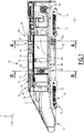
- the figure 1 represents a power train 10 of high speed train, according to an embodiment of the invention.
- the powerplant 10 is intended to be assembled with rail vehicles of the passenger transport wagon type, to form a train.
- the powerplant 10 comprises a body 12, as well as two bogies 14, 15 and two traction motors 16, 17, arranged under said body 12. Each traction motor 16, 17 is intended to set in motion the wheels of one of the bogies 14, 15.
- the powerplant 10 further comprises an electric transformer 18, connected to the traction motors 16, 17 and also arranged under the body 12.
- the box 12 has a roof 19 and a floor 20, which vertically define said box.
- the bogies 14, 15 and the traction motors 16, 17 are arranged under the floor 20.
- the box 12 also has side walls 21 ( figure 2 ).
- the body 12 has an elongated shape. We consider an orthonormal base (X, Y, Z), the direction Z representing the vertical. The body 12 mainly extends in the direction X, corresponding to a usual direction of movement of the powerplant 10. The body 12 has a front end, formed by a driving cabin 22.
- a first bogie 14 and a first traction motor 16 are located close to said front end of the body 12.
- a second bogie 15 and a second traction motor 17 are located near an opposite rear end of the body 12.
- the body 12 Adjacent to the driving cabin 22 along X, the body 12 includes a technical compartment 24. Said technical compartment is separated from the driving cabin 22 by a partition 25. The technical compartment 24 is shown in section on the figure 1 .
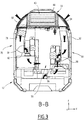
- the figures 2 and 3 show views in cross section of the body 12, at the level of said technical compartment 24, according to sectional planes AA and BB indicated on the figure 1 .
- the technical compartment 24 is delimited by the roof 19, the floor 20 and the side walls 21.
- the technical compartment 24 has a ceiling 26, which divides it along Z between an upper floor 27 and a lower floor 28.
- the ceiling 26 marks in particular a limit along Z between the side walls 21 and the roof 19, said side walls 21 being substantially flat and vertical and said roof 19 having a domed shape.
- the upper stage 27 of the technical compartment 24 comprises a rheostatic brake 30, substantially arranged between the traction motors 16 and 17 in the direction X.
- the upper stage 27 further comprises a first device 32 for ventilating the rheostatic brake 30.
- the first ventilation device 32 includes a first air intake duct 36, substantially arranged in the direction X.
- Said first duct 36 forms a closed conduit, with the exception of an inlet and an outlet situated at the level of the roof 19 of the body 12. More precisely, the inlet and the outlet of the first sheath 36 are formed, respectively, by a first air inlet mouth 38 and by a second air outlet mouth 40, incorporated into the roof 19.
- the first ventilation device 32 further comprises a first electric fan 46, capable of generating an air flow between the inlet and the outlet of the first duct 36. Said first fan 46 and the rheostatic brake 30 are arranged at the interior of said first sheath 36.
- the presence of the fan 46 makes it possible in particular to reduce the length of the first sheath 36 relative to the device described in the document FR3014396 .
- the first ventilation device 32 includes mechanical deflector elements, such as louvers 48, at the level of the first 38 and / or the second air intake mouth, in order to limit the penetration of solid particles. in the first sheath 36.
- mechanical deflector elements such as louvers 48
- the upper stage 27 of the technical compartment 24 also comprises an HVAC 50 system (Heat Ventilation Air conditioning and Cooling) capable of air conditioning the driver's cabin 22.
- the HVAC system 50 is located near the partition 25.
- the HVAC system 50 is fluidly isolated from the rest of the technical compartment 24 and comprises a third air inlet mouth (not shown) and a fourth air outlet mouth 54, incorporated into the roof 19.
- the HVAC 50 system comprises also a blower device (not shown) capable of ensuring an air movement at the level of said air inlet and outlet openings 54.
- the HVAC system 50 also includes communication conduits (not shown) passing through the partition 25 and configured for an exchange of air with the driver's cabin 22.
- the lower stage 28 of the technical compartment 24 comprises a central corridor 56.
- said central corridor has a width along Y of between 500 mm and 750 mm, preferably equal to approximately 750 mm. This width is determined to allow a comfortable passage of an operator, without significantly limiting the volume available for the powerplant equipment.
- the lower stage 28 further comprises two cooling towers 60, located on either side of the central corridor 56 and extending substantially along Z.
- the cooling towers 60 are substantially arranged above the electrical transformer 18.
- the cooling towers 60 are visible in section on the figure 2 .
- Each cooling tower 60 comprises an external envelope 62 which extends from the floor 20 to the ceiling 26, fluidly isolating said tower 60 from the atmosphere of the central corridor 56.
- traction box 64 Inside each outer casing 62 is received a traction box 64.
- Said traction box 64 comprises electrical and / or electronic equipment for controlling the traction motors 16, 17.
- the lower stage 28 further comprises at least one second ventilation device 66, associated with a cooling tower 60.
- each cooling tower 60 is associated with a second separate ventilation device 66.
- a single second ventilation device 66 will be described below.
- the second ventilation device 66 comprises a second air inlet duct 68.
- Said second duct 68 forms a closed duct, with the exception of an inlet 70 and an outlet 72.
- the inlet 70 is arranged at the level of the roof 19 and preferably formed by an air inlet mouth, similar to the first air inlet mouth 38 of the first ventilation device 32.
- the second sheath 68 extends in the upper stage 27 of the technical compartment 24, crosses the ceiling 26 and continues in the lower stage 28, where it is materialized by the external envelope 62 of the cooling tower 60.
- the outlet 72 of the second sheath 68 opens out under the floor 20, near the electrical transformer 18.
- the second ventilation device 66 also includes a second electric fan 74, located in the cooling tower 60 and capable of generating an air flow between the inlet 70 and the outlet 72.
- the lower floor 28 further comprises a plurality of technical equipment 75, installed on either side of the central corridor 56 near the side walls 21.
- Said technical equipment are for example high voltage cabinets and / or low cabinets voltage.
- the lower stage 28 also comprises a third ventilation device 76, making it possible to inject fresh air inside said lower stage 28, in particular in order to cool the technical equipment 75.
- the third ventilation device 76 is visible in section on the figure 3 .
- the third ventilation device 76 comprises a third air intake duct 78, forming a closed duct with the exception of an inlet 80 and an outlet 82.
- the inlet 80 is disposed at the level of the roof 19 and preferably formed by an air inlet mouth, similar to the first air inlet mouth 38 of the first ventilation device 32.
- the outlet 82 is arranged in the lower stage 28.
- the third ventilation device 76 further comprises a third electric fan 84, located in the lower stage 28 at the outlet 82.
- the third fan 84 is capable of blowing air outside the box 12 in the stage lower 28.
- the third ventilation device 76 further comprises at least one air outlet mouth 86 ( figure 1 ), located on the roof 19 of the body 12 and in fluid communication with the lower stage 28 of the technical compartment 24.
- suction of air on the roof 19 instead of suction on the side walls 21 makes it possible in particular to reduce the noise vis-à-vis the outside.
- the third ventilation device 76 is located at the front of the technical compartment 24; in addition, the body 12 includes a fourth ventilation device (not shown), similar to the third ventilation device 76 and intended to cool the rear of the technical compartment 24.
- the fourth ventilation device is located on the other side of the corridor 56 at the rear of technical compartment 24.
- the technical compartment 24 comprises at least one opening formed in a side wall 21 and closed reversibly by a door 88. Said door 88 gives access from the outside to the central corridor 32 of the lower floor 28.
- the walls side 21 have no permanently cleared opening.
- such side walls without opening are more aesthetic and allow more freedom in terms of design.
- the body 12 of the powerplant 10 comprises at least a fifth ventilation device 90, intended to cool the first traction motor 16.
- the fifth ventilation device 90 comprises a fifth air intake duct 92, forming a duct closed to with the exception of an inlet 94 and an outlet 96.
- the fifth sheath 92 is arranged opposite the third sheath 78 relative to the central corridor 56 of the technical compartment 24, as visible on the figure 3 .
- the inlet 94 is arranged at the level of the roof 19 and preferably formed by an air inlet mouth, similar to the first air inlet mouth 38 of the first ventilation device 32.
- the outlet 96 is arranged under the floor 20.
- the fifth ventilation device 90 further comprises a fifth electric fan 98, located in the lower stage 28 inside the fourth duct 92.
- the fifth sheath 92 is fluidly isolated from the technical compartment 24. In other words, there is no direct exchange inside the box 12 between the air circulating in the fifth sheath 92 and the air ambient in the technical compartment 24. Thus, any dust conveyed by the air circulating in the fifth sheath 92 is prevented from polluting the technical compartment 24.
- the body 12 further comprises a sixth ventilation device 99, similar to the fifth ventilation device 90 and intended to cool the second traction motor 17.
- each ventilation device 32, 66, 76, 90, 99 described above the air intake vents located on the roof 19 are preferably positioned in areas of high pressure to promote suction. Furthermore, each ventilation device has its own fan 46, 74, 84, 98 and is thus independent.
- the body 12 of the powerplant 10 further comprises a device 100 for cooling the electrical transformer 18.
- Said cooling device 100 comprises two radiators 102, connected to the electrical transformer 18 by a heat transfer fluid circuit. Each radiator 102 is disposed under the floor 20, facing the outlet 72 of the second sheath 68 associated with a cooling tower 60. Thus, the air flow generated by the second fan 74 helps to cool the electric transformer 18.
Landscapes
- Engineering & Computer Science (AREA)
- Mechanical Engineering (AREA)
- Transportation (AREA)
- Automation & Control Theory (AREA)
- Microelectronics & Electronic Packaging (AREA)
- Power Engineering (AREA)
- Physics & Mathematics (AREA)
- Thermal Sciences (AREA)
- Electric Propulsion And Braking For Vehicles (AREA)
- Motor Or Generator Cooling System (AREA)
- Hybrid Electric Vehicles (AREA)
Priority Applications (1)
| Application Number | Priority Date | Filing Date | Title |
|---|---|---|---|
| PL18191278T PL3453584T3 (pl) | 2017-08-30 | 2018-08-28 | Zespół napędowy pociągu dużych prędkości |
Applications Claiming Priority (1)
| Application Number | Priority Date | Filing Date | Title |
|---|---|---|---|
| FR1757996A FR3070353B1 (fr) | 2017-08-30 | 2017-08-30 | Motrice de train a grande vitesse |
Publications (2)
| Publication Number | Publication Date |
|---|---|
| EP3453584A1 EP3453584A1 (fr) | 2019-03-13 |
| EP3453584B1 true EP3453584B1 (fr) | 2020-03-11 |
Family
ID=60081042
Family Applications (1)
| Application Number | Title | Priority Date | Filing Date |
|---|---|---|---|
| EP18191278.3A Active EP3453584B1 (fr) | 2017-08-30 | 2018-08-28 | Motrice de train à grande vitesse |
Country Status (7)
| Country | Link |
|---|---|
| US (1) | US10864925B2 (pl) |
| EP (1) | EP3453584B1 (pl) |
| CN (1) | CN109421757B (pl) |
| ES (1) | ES2795774T3 (pl) |
| FR (1) | FR3070353B1 (pl) |
| PL (1) | PL3453584T3 (pl) |
| RU (1) | RU2760062C2 (pl) |
Cited By (1)
| Publication number | Priority date | Publication date | Assignee | Title |
|---|---|---|---|---|
| RU224555U1 (ru) * | 2024-01-09 | 2024-03-28 | Акционерное общество "Рузаевский завод химического машиностроения" (АО "Рузхиммаш") | Кузов рефрижераторного вагона |
Families Citing this family (7)
| Publication number | Priority date | Publication date | Assignee | Title |
|---|---|---|---|---|
| FR3063475B1 (fr) * | 2017-03-01 | 2019-04-12 | Alstom Transport Technologies | Motrice de train a grande vitesse |
| FR3070353B1 (fr) * | 2017-08-30 | 2019-09-06 | Speedinnov | Motrice de train a grande vitesse |
| FR3070354B1 (fr) * | 2017-08-30 | 2019-09-13 | Speedinnov | Motrice de train a grande vitesse avec surpression interne |
| FR3106556B1 (fr) | 2020-01-23 | 2022-02-11 | Speedinnov | Motrice ferroviaire avec dispositif de fixation d’équipement technique |
| KR102668847B1 (ko) * | 2021-08-17 | 2024-05-24 | 한국철도기술연구원 | 열차 객실 내 비말 차단 공조 시스템 |
| DE102021214851A1 (de) * | 2021-12-21 | 2023-06-22 | Siemens Mobility GmbH | Anordnung und Verfahren zur Befestigung eines Gerüsts |
| CN117062406B (zh) * | 2023-08-19 | 2025-08-08 | 安徽万航轨道交通装备有限公司 | 一种5g轨道机车的电器室独立通风装置 |
Family Cites Families (23)
| Publication number | Priority date | Publication date | Assignee | Title |
|---|---|---|---|---|
| JPH01141163A (ja) * | 1986-02-11 | 1989-06-02 | Alsthom Atlantique Sa | 機関車の流体冷却器用及び/又は加減抵抗器用換気装置 |
| JPH07202464A (ja) * | 1993-12-28 | 1995-08-04 | Toshiba Corp | 電子機器装置並びに電子機器装置用冷却方法及びファン装置 |
| US6238282B1 (en) * | 1999-11-30 | 2001-05-29 | General Electric Company | Locomotive cabin ventilation apparatus and method |
| FR2808487B1 (fr) * | 2000-05-04 | 2002-06-21 | Alstom | Dispositif et procede de ventilation d'equipements electriques embarques a bord d'un vehicule ferroviaire |
| DE102006032335B4 (de) * | 2006-07-12 | 2008-04-30 | Siemens Ag | Schienenfahrzeug mit einer Kühlanordnung für in einem Unterflurbereich angeordnete Komponenten |
| FR2926276B1 (fr) * | 2008-01-11 | 2010-09-03 | Alstom Transport Sa | Ensemble de ventilation d'un appareillage de vehicule ferroviaire |
| RU80150U1 (ru) * | 2008-10-01 | 2009-01-27 | Открытое акционерное общество "Уральский завод железнодорожного машиностроения" (ОАО "УЗЖМ") | Электровоз грузовой магистральный |
| JP2012101575A (ja) * | 2010-11-05 | 2012-05-31 | Toshiba Corp | 冷却装置を備えた鉄道車両 |
| US9616903B2 (en) * | 2012-08-31 | 2017-04-11 | General Electric Company | Vehicle system and method |
| CN103144646B (zh) * | 2013-03-05 | 2015-10-21 | 唐山轨道客车有限责任公司 | 轨道客车空调通风系统及轨道客车 |
| CN105379080A (zh) * | 2013-07-19 | 2016-03-02 | 株式会社东芝 | 液冷式电动机 |
| CN203358602U (zh) * | 2013-07-23 | 2013-12-25 | 株洲车城机车配件有限公司 | 一种机车制动电阻风机系统 |
| CN203450130U (zh) * | 2013-07-30 | 2014-02-26 | 南车青岛四方机车车辆股份有限公司 | 高速列车车内设备通风散热装置 |
| FR3014396B1 (fr) * | 2013-12-06 | 2017-04-28 | Alstom Transp Tech | Dispositif de refroidissement de composants, notamment pour un vehicule ferroviaire |
| FR3016206B1 (fr) * | 2014-01-08 | 2016-02-05 | Alstom Transport Sa | Dispositif de climatisation d'un compartiment, notamment pour un vehicule ferroviaire |
| CN204279454U (zh) * | 2014-11-27 | 2015-04-22 | 南车青岛四方机车车辆股份有限公司 | 一种高速动车组空调通风系统 |
| US9790644B2 (en) * | 2015-12-14 | 2017-10-17 | Harsco Technologies LLC | Vertical ride quality system for a rail vehicle |
| CN205872054U (zh) * | 2016-07-19 | 2017-01-11 | 中车青岛四方机车车辆股份有限公司 | 一种轨道车辆模块化外端间壁 |
| CN206187028U (zh) * | 2016-11-08 | 2017-05-24 | 中车青岛四方机车车辆股份有限公司 | 一种轨道交通车辆用全热换热器及轨道交通车辆 |
| FR3063475B1 (fr) * | 2017-03-01 | 2019-04-12 | Alstom Transport Technologies | Motrice de train a grande vitesse |
| FR3070353B1 (fr) * | 2017-08-30 | 2019-09-06 | Speedinnov | Motrice de train a grande vitesse |
| FR3070354B1 (fr) * | 2017-08-30 | 2019-09-13 | Speedinnov | Motrice de train a grande vitesse avec surpression interne |
| ES2867124T3 (es) * | 2017-12-19 | 2021-10-20 | Abb Power Grids Switzerland Ag | Sistema y método de refrigeración para un vehículo ferroviario de doble propulsión |
-
2017
- 2017-08-30 FR FR1757996A patent/FR3070353B1/fr not_active Expired - Fee Related
-
2018
- 2018-08-28 ES ES18191278T patent/ES2795774T3/es active Active
- 2018-08-28 EP EP18191278.3A patent/EP3453584B1/fr active Active
- 2018-08-28 PL PL18191278T patent/PL3453584T3/pl unknown
- 2018-08-29 RU RU2018131041A patent/RU2760062C2/ru active
- 2018-08-30 US US16/117,865 patent/US10864925B2/en active Active
- 2018-08-30 CN CN201811005601.6A patent/CN109421757B/zh active Active
Non-Patent Citations (1)
| Title |
|---|
| None * |
Cited By (1)
| Publication number | Priority date | Publication date | Assignee | Title |
|---|---|---|---|---|
| RU224555U1 (ru) * | 2024-01-09 | 2024-03-28 | Акционерное общество "Рузаевский завод химического машиностроения" (АО "Рузхиммаш") | Кузов рефрижераторного вагона |
Also Published As
| Publication number | Publication date |
|---|---|
| CN109421757B (zh) | 2021-09-07 |
| EP3453584A1 (fr) | 2019-03-13 |
| RU2760062C2 (ru) | 2021-11-22 |
| PL3453584T3 (pl) | 2020-11-16 |
| US10864925B2 (en) | 2020-12-15 |
| RU2018131041A (ru) | 2020-03-03 |
| CN109421757A (zh) | 2019-03-05 |
| FR3070353A1 (fr) | 2019-03-01 |
| RU2018131041A3 (pl) | 2021-09-27 |
| ES2795774T3 (es) | 2020-11-24 |
| US20190061786A1 (en) | 2019-02-28 |
| FR3070353B1 (fr) | 2019-09-06 |
Similar Documents
| Publication | Publication Date | Title |
|---|---|---|
| FR3070353B1 (fr) | Motrice de train a grande vitesse | |
| EP3450277B1 (fr) | Motrice de train à grande vitesse avec surpression interne | |
| CN104302494B (zh) | 用于机动车辆的水箱 | |
| ES2295921T3 (es) | Dispositivo de acondicionamiento de aire para vehiculo. | |
| JPH0642323U (ja) | 自動車、特に、バスに対する空気調和装置 | |
| WO2013080339A1 (ja) | 車両前部構造 | |
| CN104723834A (zh) | 用于车辆的空气调节装置 | |
| CN115867444B (zh) | 包括热调节系统的车辆 | |
| JP2007527818A (ja) | 自動車の内部換気および冷却装置 | |
| FR2703630A1 (fr) | Appareil de chauffage-ventilation et/ou de climatisation de l'habitacle d'un véhicule automobile. | |
| EP3031690B1 (fr) | Dispositif aéraulique de refroidissement d'un élément d'un véhicule ferroviaire et véhicule ferroviaire correspondant | |
| EP0566474B1 (fr) | Dispositif de chauffage-ventilation et/ou de climatisation de l'habitacle d'un véhicule automobile | |
| JP2010120483A (ja) | 鉄道車両 | |
| US6595499B2 (en) | Evaporating unit for an air acclimatizer | |
| US11097752B2 (en) | Heat sink cover and electrically operated vehicle | |
| US20240010047A1 (en) | Venturi ventilator for an enclosure | |
| JPH06344956A (ja) | 車両用走行安定化装置 | |
| HU223686B1 (hu) | Berendezés sínenfutó jármű szellőztetéséhez | |
| FR2903345A1 (fr) | Dispositif de preventilation, de ventilation, de chauffage et/ou de climatisation d'un habitacle de vehicule, mettant en oeuvre un pulseur et des unites thermoelectriques a effet peltier | |
| JP2009234310A (ja) | 軌条車両 | |
| US2718186A (en) | Fresh-air vehicle ventilating and heating system and units therefor | |
| JPH06144222A (ja) | 高速車両用通風装置 | |
| CN207565266U (zh) | 一种冷凝器风道装置及车辆空调系统 | |
| EP4269208B1 (fr) | Dispositif de climatisation d'un habitacle de véhicule et véhicule associé | |
| JPS5931444Y2 (ja) | バス等車輛のフレッシュエア−導入装置 |
Legal Events
| Date | Code | Title | Description |
|---|---|---|---|
| PUAI | Public reference made under article 153(3) epc to a published international application that has entered the european phase |
Free format text: ORIGINAL CODE: 0009012 |
|
| STAA | Information on the status of an ep patent application or granted ep patent |
Free format text: STATUS: THE APPLICATION HAS BEEN PUBLISHED |
|
| AK | Designated contracting states |
Kind code of ref document: A1 Designated state(s): AL AT BE BG CH CY CZ DE DK EE ES FI FR GB GR HR HU IE IS IT LI LT LU LV MC MK MT NL NO PL PT RO RS SE SI SK SM TR |
|
| AX | Request for extension of the european patent |
Extension state: BA ME |
|
| STAA | Information on the status of an ep patent application or granted ep patent |
Free format text: STATUS: REQUEST FOR EXAMINATION WAS MADE |
|
| 17P | Request for examination filed |
Effective date: 20190401 |
|
| RBV | Designated contracting states (corrected) |
Designated state(s): AL AT BE BG CH CY CZ DE DK EE ES FI FR GB GR HR HU IE IS IT LI LT LU LV MC MK MT NL NO PL PT RO RS SE SI SK SM TR |
|
| GRAP | Despatch of communication of intention to grant a patent |
Free format text: ORIGINAL CODE: EPIDOSNIGR1 |
|
| RIC1 | Information provided on ipc code assigned before grant |
Ipc: B61C 17/04 20060101ALI20190902BHEP Ipc: B61D 27/00 20060101ALI20190902BHEP Ipc: B61C 3/00 20060101AFI20190902BHEP |
|
| STAA | Information on the status of an ep patent application or granted ep patent |
Free format text: STATUS: GRANT OF PATENT IS INTENDED |
|
| INTG | Intention to grant announced |
Effective date: 20191010 |
|
| GRAS | Grant fee paid |
Free format text: ORIGINAL CODE: EPIDOSNIGR3 |
|
| GRAA | (expected) grant |
Free format text: ORIGINAL CODE: 0009210 |
|
| STAA | Information on the status of an ep patent application or granted ep patent |
Free format text: STATUS: THE PATENT HAS BEEN GRANTED |
|
| AK | Designated contracting states |
Kind code of ref document: B1 Designated state(s): AL AT BE BG CH CY CZ DE DK EE ES FI FR GB GR HR HU IE IS IT LI LT LU LV MC MK MT NL NO PL PT RO RS SE SI SK SM TR |
|
| REG | Reference to a national code |
Ref country code: GB Ref legal event code: FG4D Free format text: NOT ENGLISH |
|
| REG | Reference to a national code |
Ref country code: CH Ref legal event code: EP |
|
| REG | Reference to a national code |
Ref country code: AT Ref legal event code: REF Ref document number: 1242782 Country of ref document: AT Kind code of ref document: T Effective date: 20200315 |
|
| REG | Reference to a national code |
Ref country code: IE Ref legal event code: FG4D Free format text: LANGUAGE OF EP DOCUMENT: FRENCH |
|
| REG | Reference to a national code |
Ref country code: DE Ref legal event code: R096 Ref document number: 602018002986 Country of ref document: DE |
|
| REG | Reference to a national code |
Ref country code: CH Ref legal event code: NV Representative=s name: DENNEMEYER AG, CH |
|
| REG | Reference to a national code |
Ref country code: SE Ref legal event code: TRGR |
|
| PG25 | Lapsed in a contracting state [announced via postgrant information from national office to epo] |
Ref country code: NO Free format text: LAPSE BECAUSE OF FAILURE TO SUBMIT A TRANSLATION OF THE DESCRIPTION OR TO PAY THE FEE WITHIN THE PRESCRIBED TIME-LIMIT Effective date: 20200611 Ref country code: FI Free format text: LAPSE BECAUSE OF FAILURE TO SUBMIT A TRANSLATION OF THE DESCRIPTION OR TO PAY THE FEE WITHIN THE PRESCRIBED TIME-LIMIT Effective date: 20200311 Ref country code: RS Free format text: LAPSE BECAUSE OF FAILURE TO SUBMIT A TRANSLATION OF THE DESCRIPTION OR TO PAY THE FEE WITHIN THE PRESCRIBED TIME-LIMIT Effective date: 20200311 |
|
| REG | Reference to a national code |
Ref country code: NL Ref legal event code: MP Effective date: 20200311 |
|
| PG25 | Lapsed in a contracting state [announced via postgrant information from national office to epo] |
Ref country code: HR Free format text: LAPSE BECAUSE OF FAILURE TO SUBMIT A TRANSLATION OF THE DESCRIPTION OR TO PAY THE FEE WITHIN THE PRESCRIBED TIME-LIMIT Effective date: 20200311 Ref country code: BG Free format text: LAPSE BECAUSE OF FAILURE TO SUBMIT A TRANSLATION OF THE DESCRIPTION OR TO PAY THE FEE WITHIN THE PRESCRIBED TIME-LIMIT Effective date: 20200611 Ref country code: GR Free format text: LAPSE BECAUSE OF FAILURE TO SUBMIT A TRANSLATION OF THE DESCRIPTION OR TO PAY THE FEE WITHIN THE PRESCRIBED TIME-LIMIT Effective date: 20200612 Ref country code: LV Free format text: LAPSE BECAUSE OF FAILURE TO SUBMIT A TRANSLATION OF THE DESCRIPTION OR TO PAY THE FEE WITHIN THE PRESCRIBED TIME-LIMIT Effective date: 20200311 |
|
| REG | Reference to a national code |
Ref country code: LT Ref legal event code: MG4D |
|
| PG25 | Lapsed in a contracting state [announced via postgrant information from national office to epo] |
Ref country code: NL Free format text: LAPSE BECAUSE OF FAILURE TO SUBMIT A TRANSLATION OF THE DESCRIPTION OR TO PAY THE FEE WITHIN THE PRESCRIBED TIME-LIMIT Effective date: 20200311 |
|
| PG25 | Lapsed in a contracting state [announced via postgrant information from national office to epo] |
Ref country code: PT Free format text: LAPSE BECAUSE OF FAILURE TO SUBMIT A TRANSLATION OF THE DESCRIPTION OR TO PAY THE FEE WITHIN THE PRESCRIBED TIME-LIMIT Effective date: 20200805 Ref country code: CZ Free format text: LAPSE BECAUSE OF FAILURE TO SUBMIT A TRANSLATION OF THE DESCRIPTION OR TO PAY THE FEE WITHIN THE PRESCRIBED TIME-LIMIT Effective date: 20200311 Ref country code: RO Free format text: LAPSE BECAUSE OF FAILURE TO SUBMIT A TRANSLATION OF THE DESCRIPTION OR TO PAY THE FEE WITHIN THE PRESCRIBED TIME-LIMIT Effective date: 20200311 Ref country code: IS Free format text: LAPSE BECAUSE OF FAILURE TO SUBMIT A TRANSLATION OF THE DESCRIPTION OR TO PAY THE FEE WITHIN THE PRESCRIBED TIME-LIMIT Effective date: 20200711 Ref country code: EE Free format text: LAPSE BECAUSE OF FAILURE TO SUBMIT A TRANSLATION OF THE DESCRIPTION OR TO PAY THE FEE WITHIN THE PRESCRIBED TIME-LIMIT Effective date: 20200311 Ref country code: SM Free format text: LAPSE BECAUSE OF FAILURE TO SUBMIT A TRANSLATION OF THE DESCRIPTION OR TO PAY THE FEE WITHIN THE PRESCRIBED TIME-LIMIT Effective date: 20200311 Ref country code: LT Free format text: LAPSE BECAUSE OF FAILURE TO SUBMIT A TRANSLATION OF THE DESCRIPTION OR TO PAY THE FEE WITHIN THE PRESCRIBED TIME-LIMIT Effective date: 20200311 Ref country code: SK Free format text: LAPSE BECAUSE OF FAILURE TO SUBMIT A TRANSLATION OF THE DESCRIPTION OR TO PAY THE FEE WITHIN THE PRESCRIBED TIME-LIMIT Effective date: 20200311 |
|
| REG | Reference to a national code |
Ref country code: AT Ref legal event code: MK05 Ref document number: 1242782 Country of ref document: AT Kind code of ref document: T Effective date: 20200311 |
|
| REG | Reference to a national code |
Ref country code: ES Ref legal event code: FG2A Ref document number: 2795774 Country of ref document: ES Kind code of ref document: T3 Effective date: 20201124 |
|
| REG | Reference to a national code |
Ref country code: DE Ref legal event code: R097 Ref document number: 602018002986 Country of ref document: DE |
|
| PLBE | No opposition filed within time limit |
Free format text: ORIGINAL CODE: 0009261 |
|
| STAA | Information on the status of an ep patent application or granted ep patent |
Free format text: STATUS: NO OPPOSITION FILED WITHIN TIME LIMIT |
|
| PG25 | Lapsed in a contracting state [announced via postgrant information from national office to epo] |
Ref country code: DK Free format text: LAPSE BECAUSE OF FAILURE TO SUBMIT A TRANSLATION OF THE DESCRIPTION OR TO PAY THE FEE WITHIN THE PRESCRIBED TIME-LIMIT Effective date: 20200311 Ref country code: AT Free format text: LAPSE BECAUSE OF FAILURE TO SUBMIT A TRANSLATION OF THE DESCRIPTION OR TO PAY THE FEE WITHIN THE PRESCRIBED TIME-LIMIT Effective date: 20200311 |
|
| 26N | No opposition filed |
Effective date: 20201214 |
|
| PG25 | Lapsed in a contracting state [announced via postgrant information from national office to epo] |
Ref country code: SI Free format text: LAPSE BECAUSE OF FAILURE TO SUBMIT A TRANSLATION OF THE DESCRIPTION OR TO PAY THE FEE WITHIN THE PRESCRIBED TIME-LIMIT Effective date: 20200311 |
|
| PG25 | Lapsed in a contracting state [announced via postgrant information from national office to epo] |
Ref country code: MC Free format text: LAPSE BECAUSE OF FAILURE TO SUBMIT A TRANSLATION OF THE DESCRIPTION OR TO PAY THE FEE WITHIN THE PRESCRIBED TIME-LIMIT Effective date: 20200311 |
|
| PG25 | Lapsed in a contracting state [announced via postgrant information from national office to epo] |
Ref country code: LU Free format text: LAPSE BECAUSE OF NON-PAYMENT OF DUE FEES Effective date: 20200828 |
|
| PG25 | Lapsed in a contracting state [announced via postgrant information from national office to epo] |
Ref country code: IE Free format text: LAPSE BECAUSE OF NON-PAYMENT OF DUE FEES Effective date: 20200828 |
|
| PG25 | Lapsed in a contracting state [announced via postgrant information from national office to epo] |
Ref country code: MT Free format text: LAPSE BECAUSE OF FAILURE TO SUBMIT A TRANSLATION OF THE DESCRIPTION OR TO PAY THE FEE WITHIN THE PRESCRIBED TIME-LIMIT Effective date: 20200311 Ref country code: CY Free format text: LAPSE BECAUSE OF FAILURE TO SUBMIT A TRANSLATION OF THE DESCRIPTION OR TO PAY THE FEE WITHIN THE PRESCRIBED TIME-LIMIT Effective date: 20200311 |
|
| PG25 | Lapsed in a contracting state [announced via postgrant information from national office to epo] |
Ref country code: MK Free format text: LAPSE BECAUSE OF FAILURE TO SUBMIT A TRANSLATION OF THE DESCRIPTION OR TO PAY THE FEE WITHIN THE PRESCRIBED TIME-LIMIT Effective date: 20200311 Ref country code: AL Free format text: LAPSE BECAUSE OF FAILURE TO SUBMIT A TRANSLATION OF THE DESCRIPTION OR TO PAY THE FEE WITHIN THE PRESCRIBED TIME-LIMIT Effective date: 20200311 |
|
| P01 | Opt-out of the competence of the unified patent court (upc) registered |
Effective date: 20231025 |
|
| PGFP | Annual fee paid to national office [announced via postgrant information from national office to epo] |
Ref country code: ES Payment date: 20250926 Year of fee payment: 8 |
|
| PGFP | Annual fee paid to national office [announced via postgrant information from national office to epo] |
Ref country code: DE Payment date: 20250820 Year of fee payment: 8 |
|
| PGFP | Annual fee paid to national office [announced via postgrant information from national office to epo] |
Ref country code: PL Payment date: 20250816 Year of fee payment: 8 Ref country code: TR Payment date: 20250819 Year of fee payment: 8 Ref country code: IT Payment date: 20250825 Year of fee payment: 8 |
|
| PGFP | Annual fee paid to national office [announced via postgrant information from national office to epo] |
Ref country code: BE Payment date: 20250820 Year of fee payment: 8 Ref country code: GB Payment date: 20250821 Year of fee payment: 8 |
|
| PGFP | Annual fee paid to national office [announced via postgrant information from national office to epo] |
Ref country code: FR Payment date: 20250828 Year of fee payment: 8 |
|
| PGFP | Annual fee paid to national office [announced via postgrant information from national office to epo] |
Ref country code: CH Payment date: 20250901 Year of fee payment: 8 Ref country code: SE Payment date: 20250820 Year of fee payment: 8 |