EP3452874B1 - Spiral d'horlogerie - Google Patents
Spiral d'horlogerie Download PDFInfo
- Publication number
- EP3452874B1 EP3452874B1 EP17721468.1A EP17721468A EP3452874B1 EP 3452874 B1 EP3452874 B1 EP 3452874B1 EP 17721468 A EP17721468 A EP 17721468A EP 3452874 B1 EP3452874 B1 EP 3452874B1
- Authority
- EP
- European Patent Office
- Prior art keywords
- balance spring
- relief angle
- hairspring
- turns
- strip
- Prior art date
- Legal status (The legal status is an assumption and is not a legal conclusion. Google has not performed a legal analysis and makes no representation as to the accuracy of the status listed.)
- Active
Links
- 238000000708 deep reactive-ion etching Methods 0.000 claims description 8
- XUIMIQQOPSSXEZ-UHFFFAOYSA-N Silicon Chemical compound [Si] XUIMIQQOPSSXEZ-UHFFFAOYSA-N 0.000 claims description 5
- 238000004519 manufacturing process Methods 0.000 claims description 5
- 229910052710 silicon Inorganic materials 0.000 claims description 5
- 239000010703 silicon Substances 0.000 claims description 5
- 229910052582 BN Inorganic materials 0.000 claims description 2
- PZNSFCLAULLKQX-UHFFFAOYSA-N Boron nitride Chemical compound N#B PZNSFCLAULLKQX-UHFFFAOYSA-N 0.000 claims description 2
- 239000000919 ceramic Substances 0.000 claims description 2
- 229910003460 diamond Inorganic materials 0.000 claims description 2
- 239000010432 diamond Substances 0.000 claims description 2
- 239000011521 glass Substances 0.000 claims description 2
- HBMJWWWQQXIZIP-UHFFFAOYSA-N silicon carbide Chemical compound [Si+]#[C-] HBMJWWWQQXIZIP-UHFFFAOYSA-N 0.000 claims description 2
- 229910010271 silicon carbide Inorganic materials 0.000 claims description 2
- 238000000034 method Methods 0.000 description 3
- 239000000463 material Substances 0.000 description 2
- 230000035939 shock Effects 0.000 description 2
- VYPSYNLAJGMNEJ-UHFFFAOYSA-N Silicium dioxide Chemical compound O=[Si]=O VYPSYNLAJGMNEJ-UHFFFAOYSA-N 0.000 description 1
- 230000000694 effects Effects 0.000 description 1
- 238000005530 etching Methods 0.000 description 1
- 238000003754 machining Methods 0.000 description 1
- 230000007246 mechanism Effects 0.000 description 1
- 238000000465 moulding Methods 0.000 description 1
- 230000010355 oscillation Effects 0.000 description 1
- 238000002161 passivation Methods 0.000 description 1
- 230000001105 regulatory effect Effects 0.000 description 1
- 229910052814 silicon oxide Inorganic materials 0.000 description 1
Images

Classifications
-
- G—PHYSICS
- G04—HOROLOGY
- G04B—MECHANICALLY-DRIVEN CLOCKS OR WATCHES; MECHANICAL PARTS OF CLOCKS OR WATCHES IN GENERAL; TIME PIECES USING THE POSITION OF THE SUN, MOON OR STARS
- G04B17/00—Mechanisms for stabilising frequency
- G04B17/04—Oscillators acting by spring tension
- G04B17/06—Oscillators with hairsprings, e.g. balance
- G04B17/066—Manufacture of the spiral spring
Definitions
- the present invention relates to a hairspring intended to be associated with a balance to form an oscillator (regulating member) of a watch movement.
- the document WO 2017/023584 A1 discloses a hairspring for watch oscillator and aims to prevent the turns from sticking to each other by eliminating the electrostatic charges of the hairspring.
- the present invention aims to remedy this drawback or at least to reduce it, and for this purpose proposes a hairspring according to claim 1 and a process for manufacturing hairspring according to claim 9.
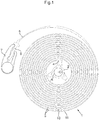
- a hairspring 1 is intended to be mounted on a balance axis A via a ferrule 2 to form with the balance the oscillator of a watch movement.
- the hairspring 1 consists of a blade 3 wound in a spiral from an inner end 4 joined to the ferrule 2 to an outer end 5 intended to be fixed to the frame of the movement by means of one or more members.
- the outer end 5 of the blade 3 is extended by a rigid fixing part 6 which is held by a clamp 7 mounted on the frame of the movement, as described in the patent EP 1780611 of the plaintiff.
- the outer end 5 could however be fixed to the frame in another way, for example by means of a traditional peg.
- the assembly comprising the blade 3, the ferrule 2 and the rigid fixing part 6 can be monolithic, as shown, and be made of silicon by deep reactive ion etching (DRIE).
- DRIE deep reactive ion etching
- the mean plane in which the blade 3 is wound is designated by P at the figure 2 .
- This mean plane P is located halfway between an upper surface 8 and a lower surface 9 of the blade 3, surfaces 8, 9 which typically are plane and parallel.
- This mean plane P crosses the two flanks 10, 11 of the blade 3 which each connect the upper surface 8 to the lower surface 9.
- These two flanks 10, 11 are rectilinear in radial section, that is to say in a plane containing the imaginary axis of oscillation O of hairspring 1, and have a low roughness.
- the sides 10, 11 of the blade 3, in radial section are not perpendicular to the mean plane P but are each inclined by a draft angle ⁇ (visible only at the figure 2 ) greater than or equal to 2.5 °, preferably greater than or equal to 3 °, more preferably still greater than or equal to 4 °, more preferably still greater than or equal to 5 ° and typically between 2.5 ° and 20 °, more particularly between 2.5 ° and 6 °, giving the radial section of the blade 3 a trapezoidal shape.
- a draft angle ⁇ visible only at the figure 2
- the sides 10, 11 thus form between them, in radial section, an angle ⁇ greater than or equal to 5 °, preferably greater than or equal to 6 °, preferably still greater than or equal to 8 °, preferably still greater than or equal to 10 °, and typically between 5 ° and 40 °, more particularly between 5 ° and 12 °.
- Such angles can be obtained by adjusting the parameters of the DRIE process, in particular the ratio between the etching and passivation times.
- each side of the monolithic assembly 2, 3, 6 can be tilted from the draft angle a.
- the present invention does not however exclude that the clearance angle ⁇ differs from one side to another.
- the turns of the hairspring 1 can move radially and touch each other.
- the contact between the turns cannot be plane, unless the turns are twisted.
- the absence of plane contact over a sufficient height prevents the turns from adhering to each other.
- the higher the clearance angle ⁇ the more difficult it is for the turns to twist sufficiently.
- the risk of sticking the turns together is thus reduced.
- the present invention also makes it possible to reduce the risk of sticking between the first turn and the shell 2 and between the last turn and the clamp 7 or other member for fixing to the frame of the movement, in the event of impact or improper handling.
- Another advantage of the hairspring according to the present invention is that, thanks to its straight sides 10, 11, it is relatively easy to manufacture.
- the present invention is applicable to materials other than silicon, for example silicon carbide, boron nitride, glasses, ceramics or diamond, and other manufacturing processes. than DRIE engraving, for example laser machining, molding, etc.
- the hairspring according to the invention can be coated with one or more layers, for example with a layer of silicon oxide in the case of a silicon hairspring.
Landscapes
- Engineering & Computer Science (AREA)
- Manufacturing & Machinery (AREA)
- Physics & Mathematics (AREA)
- General Physics & Mathematics (AREA)
- Micromachines (AREA)
Description
- La présente invention concerne un spiral destiné à être associé à un balancier pour former un oscillateur (organe réglant) d'un mouvement horloger. Le document
WO 2017/023584 A1 divulgue un spiral pour oscillateur horloger et a pour but d'éviter que les spires ne se collent l'une à l'autre en éliminant les charges électrostatiques du spiral. - Les nouvelles techniques de fabrication utilisées dans l'horlogerie, telles que la gravure ionique réactive profonde (DRIE), et les nouveaux matériaux, tels que le silicium, permettent l'obtention de composants de très grande qualité. Ces avancées technologiques ont contribué à améliorer la précision, le rendement et la robustesse des mécanismes horlogers. Cependant, dans le cas des spiraux, on a constaté un risque de collage des spires entre elles lors de chocs reçus par le mouvement ou de mauvaises manipulations au montage. Ce risque tient probablement à l'excellent état de surface des flancs du spiral. Dès que deux spires se touchent sous l'effet d'un choc ou d'une mauvaise manipulation, leurs flancs en contact peuvent facilement adhérer l'un à l'autre car ils sont lisses.
- La présente invention vise à remédier à cet inconvénient ou au moins à l'atténuer, et propose à cette fin un spiral selon la revendication 1 et un procédé de fabrication de spiral selon la revendication 9.
- D'autres caractéristiques et avantages de la présente invention apparaîtront à la lecture de la description détaillée suivante faite en référence aux dessins schématiques annexés dans lesquels :
- la
figure 1 est une vue de dessus montrant un spiral selon un mode de réalisation particulier de l'invention, avec sa virole, et une pince de fixation de l'extrémité extérieure du spiral ; - la
figure 2 est une section radiale à travers trois spires adjacentes du spiral illustré à lafigure 1 . - En référence aux
figures 1 et2 , un spiral 1 selon l'invention est destiné à être monté sur un axe de balancier A par l'intermédiaire d'une virole 2 pour former avec le balancier l'oscillateur d'un mouvement horloger. Le spiral 1 est constitué d'une lame 3 enroulée en spirale depuis une extrémité intérieure 4 jointe à la virole 2 jusqu'à une extrémité extérieure 5 destinée à être fixée au bâti du mouvement par l'intermédiaire d'un ou plusieurs organes. Dans l'exemple représenté, l'extrémité extérieure 5 de la lame 3 est prolongée par une partie rigide de fixation 6 qui est tenue par une pince 7 montée sur le bâti du mouvement, comme décrit dans le brevetEP 1780611 de la demanderesse. L'extrémité extérieure 5 pourrait cependant être fixée au bâti d'une autre manière, par exemple au moyen d'un piton traditionnel. L'ensemble comprenant la lame 3, la virole 2 et la partie rigide de fixation 6 peut être monolithique, comme représenté, et être fabriqué en silicium par gravure ionique réactive profonde (DRIE). Le plan moyen dans lequel la lame 3 est enroulée est désigné par P à lafigure 2 . Ce plan moyen P est situé à mi-hauteur entre une surface supérieure 8 et une surface inférieure 9 de la lame 3, surfaces 8, 9 qui typiquement sont planes et parallèles. Ce plan moyen P traverse les deux flancs 10, 11 de la lame 3 qui relient chacun la surface supérieure 8 à la surface inférieure 9. Ces deux flancs 10, 11 sont rectilignes en section radiale, c'est-à-dire dans un plan contenant l'axe imaginaire d'oscillation O du spiral 1, et présentent une faible rugosité. - Conformément à l'invention, les flancs 10, 11 de la lame 3, en section radiale, ne sont pas perpendiculaires au plan moyen P mais sont chacun inclinés d'un angle de dépouille α (visible uniquement à la
figure 2 ) supérieur ou égal à 2,5°, de préférence supérieur ou égal à 3°, de préférence encore supérieur ou égal à 4°, de préférence encore supérieur ou égal à 5° et typiquement compris entre 2,5° et 20°, plus particulièrement entre 2,5° et 6°, donnant à la section radiale de la lame 3 une forme trapézoïdale. Les flancs 10, 11 forment ainsi entre eux, en section radiale, un angle β supérieur ou égal à 5°, de préférence supérieur ou égal à 6°, de préférence encore supérieur ou égal à 8°, de préférence encore supérieur ou égal à 10°, et typiquement compris entre 5° et 40°, plus particulièrement entre 5° et 12°. De tels angles peuvent être obtenus en ajustant les paramètres du procédé DRIE, notamment le rapport entre les temps de gravure et de passivation. En pratique, chaque flanc de l'ensemble monolithique 2, 3, 6 peut être incliné de l'angle de dépouille a. La présente invention n'exclut toutefois pas que l'angle de dépouille α diffère d'un flanc à un autre. - Dans le cas d'un choc ou d'une mauvaise manipulation, les spires du spiral 1 peuvent se déplacer radialement et se toucher. Toutefois, grâce à l'inclinaison des flancs 10, 11, le contact entre les spires ne peut pas être plan, à moins que les spires se tordent. L'absence de contact plan sur une hauteur suffisante empêche les spires d'adhérer les unes aux autres. Plus l'angle de dépouille α est élevé, plus il est difficile pour les spires de se tordre suffisamment. Le risque de collage des spires entre elles est ainsi diminué. On notera que la présente invention permet également de réduire le risque de collage entre la première spire et la virole 2 et entre la dernière spire et la pince 7 ou autre organe de fixation au bâti du mouvement, en cas de choc ou de mauvaise manipulation. Un autre avantage du spiral selon la présente invention est que, grâce à ses flancs 10, 11 rectilignes, il est relativement facile à fabriquer.
- Il va de soi que la présente invention est applicable à d'autres matériaux que le silicium, par exemple au carbure de silicium, au nitrure de bore, à des verres, à des céramiques ou au diamant, et à d'autres procédés de fabrication que la gravure DRIE, par exemple l'usinage laser, le moulage, etc. Le spiral selon l'invention peut être revêtu d'une ou plusieurs couches, par exemple d'une couche d'oxyde de silicium dans le cas d'un spiral en silicium.
Claims (9)
- Spiral pour oscillateur horloger comprenant une lame (3) formant plusieurs spires selon un plan moyen (P), la lame (3) comprenant une surface supérieure (8), une surface inférieure (9) et des premier et deuxième flancs (10, 11) opposés, traversés par le plan moyen (P) et s'étendant chacun de la surface supérieure (8) à la surface inférieure (9), caractérisé en ce que sur au moins une partie de la longueur de la lame (3) les premier et deuxième flancs (10, 11), en section radiale, sont rectilignes et inclinés d'un angle de dépouille (a) d'au moins 2,5°.
- Spiral selon la revendication 1, caractérisé en ce que ledit angle de dépouille (a) est d'au moins 3°.
- Spiral selon la revendication 2, caractérisé en ce que ledit angle de dépouille (a) est d'au moins 4°.
- Spiral selon la revendication 3, caractérisé en ce que ledit angle de dépouille (a) est d'au moins 5°.
- Spiral selon l'une quelconque des revendications précédentes, caractérisé en ce que ledit angle de dépouille (a) est d'au plus 20°.
- Spiral selon la revendication 5, caractérisé en ce que ledit angle de dépouille (a) est d'au plus 6°.
- Spiral selon l'une quelconque des revendications précédentes, caractérisé en ce que ledit angle de dépouille (a) est le même pour les premier et deuxième flancs (10, 11).
- Spiral selon l'une quelconque des revendications précédentes, caractérisé en ce qu'il est réalisé, au moins en partie, en silicium, en carbure de silicium, en nitrure de bore, en verre, en céramique ou en diamant.
- Procédé de fabrication d'un spiral selon l'une quelconque des revendications précédentes, caractérisé en ce qu'il comprend une étape de gravure ionique réactive profonde, ledit angle de dépouille (a) étant obtenu en ajustant des paramètres de l'étape de gravure ionique réactive profonde.
Applications Claiming Priority (2)
| Application Number | Priority Date | Filing Date | Title |
|---|---|---|---|
| EP16167917 | 2016-05-02 | ||
| PCT/IB2017/052407 WO2017191533A1 (fr) | 2016-05-02 | 2017-04-26 | Spiral d'horlogerie |
Publications (2)
| Publication Number | Publication Date |
|---|---|
| EP3452874A1 EP3452874A1 (fr) | 2019-03-13 |
| EP3452874B1 true EP3452874B1 (fr) | 2020-06-10 |
Family
ID=55910166
Family Applications (1)
| Application Number | Title | Priority Date | Filing Date |
|---|---|---|---|
| EP17721468.1A Active EP3452874B1 (fr) | 2016-05-02 | 2017-04-26 | Spiral d'horlogerie |
Country Status (2)
| Country | Link |
|---|---|
| EP (1) | EP3452874B1 (fr) |
| WO (1) | WO2017191533A1 (fr) |
Families Citing this family (2)
| Publication number | Priority date | Publication date | Assignee | Title |
|---|---|---|---|---|
| EP3418816B1 (fr) * | 2017-06-20 | 2019-10-16 | Lakeview Innovation Ltd. | Balancier spiral comprenant une section transversale en forme de losange pour un mécanisme d'horlogerie d'un mouvement de montre et procédé de fabrication du balancier spiral |
| WO2019103977A1 (fr) * | 2017-11-21 | 2019-05-31 | Firehouse Horology, Inc. | Géométries de spiraux pour montres mécaniques obtenues par nanofabrication |
Citations (2)
| Publication number | Priority date | Publication date | Assignee | Title |
|---|---|---|---|---|
| WO2014023584A1 (fr) * | 2012-08-07 | 2014-02-13 | Eta Sa Manufacture Horlogere Suisse | Système oscillant pour mouvement d'horlogerie |
| EP2804054A1 (fr) * | 2013-05-17 | 2014-11-19 | ETA SA Manufacture Horlogère Suisse | Dispositif anti-adhésion d'un spiral sur un pont |
Family Cites Families (5)
| Publication number | Priority date | Publication date | Assignee | Title |
|---|---|---|---|---|
| CH327796A (fr) * | 1954-02-22 | 1958-02-15 | Horlogerie Suisse S A Asuag | Spiral plat |
| CH700805B1 (fr) | 2005-10-25 | 2010-10-29 | Patek Philippe Sa Geneve | Dispositif régulateur pour pièce d'horlogerie et mouvement d'horlogerie comprenant un tel dispositif. |
| KR20090103819A (ko) * | 2008-03-28 | 2009-10-01 | 니바록스-파 에스.에이. | 일체형의 헤어스프링 및 이의 제조 방법 |
| CH704686B1 (fr) * | 2011-03-23 | 2016-06-30 | Lvmh Swiss Mft Sa | Ressort horloger pour montre-bracelet. |
| FR2992745B1 (fr) * | 2012-06-28 | 2015-03-27 | Philippe Rhul | Spiral guide de la lumiere, systeme de controle in-situ d'un mouvement d'horlogerie equipe de ce spiral, et dispositif portable de controle |
-
2017
- 2017-04-26 WO PCT/IB2017/052407 patent/WO2017191533A1/fr unknown
- 2017-04-26 EP EP17721468.1A patent/EP3452874B1/fr active Active
Patent Citations (2)
| Publication number | Priority date | Publication date | Assignee | Title |
|---|---|---|---|---|
| WO2014023584A1 (fr) * | 2012-08-07 | 2014-02-13 | Eta Sa Manufacture Horlogere Suisse | Système oscillant pour mouvement d'horlogerie |
| EP2804054A1 (fr) * | 2013-05-17 | 2014-11-19 | ETA SA Manufacture Horlogère Suisse | Dispositif anti-adhésion d'un spiral sur un pont |
Also Published As
| Publication number | Publication date |
|---|---|
| WO2017191533A1 (fr) | 2017-11-09 |
| EP3452874A1 (fr) | 2019-03-13 |
Similar Documents
| Publication | Publication Date | Title |
|---|---|---|
| EP2407831B1 (fr) | Spiral pour oscillateur balancier de pièce d'horlogerie et son procédé de fabrication | |
| EP3548973B1 (fr) | Dispositif pour pièce d'horlogerie, mouvement horloger et pièce d'horlogerie comprenant un tel dispositif | |
| EP0559006B1 (fr) | Dispositif d'entretoisement pour les lames d'un train de scies et train de scies utilisant un tel dispositif | |
| EP3452874B1 (fr) | Spiral d'horlogerie | |
| EP3623876A1 (fr) | Virole fendue à ouverture non circulaire | |
| EP2796940A2 (fr) | Composant horloger destiné à recevoir un organe par chassage | |
| EP3098669A1 (fr) | Spiral destiné à être serré par une rondelle élastique | |
| EP2952971A1 (fr) | Ancre pour mécanisme d'échappement d'un mouvement de montre | |
| EP3159746A1 (fr) | Spiral en silicium fortement dopé pour pièce d'horlogerie | |
| EP3792700A1 (fr) | Oscillateur horloger a pivot flexible | |
| EP2887152B1 (fr) | Spiral polygonal pour un résonateur horloger | |
| WO2016026730A1 (fr) | Aiguille de montre | |
| EP3037893B1 (fr) | Composant micromécanique ou horloger à guidage flexible | |
| CH706645A1 (fr) | Système d'accouplement solidaire d'une pièce en matériau cassant à une axe métallique. | |
| CH714165B1 (fr) | Dispositif pour pièce d'horlogerie, mouvement horloger et pièce d'horlogerie comprenant un tel dispositif. | |
| EP3023844A1 (fr) | Virole flexible | |
| CH714032A2 (fr) | Procédé de réalisation d'un mécanisme de guidage flexible pour oscillateur mécanique d'horlogerie. | |
| EP3432082B1 (fr) | Organe reglant | |
| EP3499318B1 (fr) | Système oscillant pour montre | |
| CH703271A2 (fr) | Résonateur thermocompensé aux premier et second ordres. | |
| EP3422117B1 (fr) | Palier amortisseur de choc pour un axe d'un mobile d'une pièce d horlogerie | |
| CH716692B1 (fr) | Procédé de fabrication d'un composant, typiquement horloger, en silicium. | |
| EP2977834B1 (fr) | Palier amortisseur de choc pour pièce d'horlogerie | |
| CH700585B1 (fr) | Mouvement d'horlogerie à échappement à ancre. | |
| EP3644129A1 (fr) | Organe de guidage flexible |
Legal Events
| Date | Code | Title | Description |
|---|---|---|---|
| STAA | Information on the status of an ep patent application or granted ep patent |
Free format text: STATUS: UNKNOWN |
|
| STAA | Information on the status of an ep patent application or granted ep patent |
Free format text: STATUS: THE INTERNATIONAL PUBLICATION HAS BEEN MADE |
|
| PUAI | Public reference made under article 153(3) epc to a published international application that has entered the european phase |
Free format text: ORIGINAL CODE: 0009012 |
|
| STAA | Information on the status of an ep patent application or granted ep patent |
Free format text: STATUS: REQUEST FOR EXAMINATION WAS MADE |
|
| 17P | Request for examination filed |
Effective date: 20181012 |
|
| AK | Designated contracting states |
Kind code of ref document: A1 Designated state(s): AL AT BE BG CH CY CZ DE DK EE ES FI FR GB GR HR HU IE IS IT LI LT LU LV MC MK MT NL NO PL PT RO RS SE SI SK SM TR |
|
| AX | Request for extension of the european patent |
Extension state: BA ME |
|
| DAV | Request for validation of the european patent (deleted) | ||
| DAX | Request for extension of the european patent (deleted) | ||
| GRAP | Despatch of communication of intention to grant a patent |
Free format text: ORIGINAL CODE: EPIDOSNIGR1 |
|
| STAA | Information on the status of an ep patent application or granted ep patent |
Free format text: STATUS: GRANT OF PATENT IS INTENDED |
|
| INTG | Intention to grant announced |
Effective date: 20200113 |
|
| GRAS | Grant fee paid |
Free format text: ORIGINAL CODE: EPIDOSNIGR3 |
|
| GRAA | (expected) grant |
Free format text: ORIGINAL CODE: 0009210 |
|
| STAA | Information on the status of an ep patent application or granted ep patent |
Free format text: STATUS: THE PATENT HAS BEEN GRANTED |
|
| AK | Designated contracting states |
Kind code of ref document: B1 Designated state(s): AL AT BE BG CH CY CZ DE DK EE ES FI FR GB GR HR HU IE IS IT LI LT LU LV MC MK MT NL NO PL PT RO RS SE SI SK SM TR |
|
| REG | Reference to a national code |
Ref country code: GB Ref legal event code: FG4D Free format text: NOT ENGLISH |
|
| REG | Reference to a national code |
Ref country code: CH Ref legal event code: EP Ref country code: AT Ref legal event code: REF Ref document number: 1279675 Country of ref document: AT Kind code of ref document: T Effective date: 20200615 |
|
| REG | Reference to a national code |
Ref country code: IE Ref legal event code: FG4D Free format text: LANGUAGE OF EP DOCUMENT: FRENCH |
|
| REG | Reference to a national code |
Ref country code: DE Ref legal event code: R096 Ref document number: 602017018001 Country of ref document: DE |
|
| REG | Reference to a national code |
Ref country code: CH Ref legal event code: NV Representative=s name: MICHELI AND CIE SA, CH |
|
| REG | Reference to a national code |
Ref country code: LT Ref legal event code: MG4D |
|
| PG25 | Lapsed in a contracting state [announced via postgrant information from national office to epo] |
Ref country code: LT Free format text: LAPSE BECAUSE OF FAILURE TO SUBMIT A TRANSLATION OF THE DESCRIPTION OR TO PAY THE FEE WITHIN THE PRESCRIBED TIME-LIMIT Effective date: 20200610 Ref country code: GR Free format text: LAPSE BECAUSE OF FAILURE TO SUBMIT A TRANSLATION OF THE DESCRIPTION OR TO PAY THE FEE WITHIN THE PRESCRIBED TIME-LIMIT Effective date: 20200911 Ref country code: NO Free format text: LAPSE BECAUSE OF FAILURE TO SUBMIT A TRANSLATION OF THE DESCRIPTION OR TO PAY THE FEE WITHIN THE PRESCRIBED TIME-LIMIT Effective date: 20200910 Ref country code: FI Free format text: LAPSE BECAUSE OF FAILURE TO SUBMIT A TRANSLATION OF THE DESCRIPTION OR TO PAY THE FEE WITHIN THE PRESCRIBED TIME-LIMIT Effective date: 20200610 Ref country code: SE Free format text: LAPSE BECAUSE OF FAILURE TO SUBMIT A TRANSLATION OF THE DESCRIPTION OR TO PAY THE FEE WITHIN THE PRESCRIBED TIME-LIMIT Effective date: 20200610 |
|
| REG | Reference to a national code |
Ref country code: NL Ref legal event code: MP Effective date: 20200610 |
|
| PG25 | Lapsed in a contracting state [announced via postgrant information from national office to epo] |
Ref country code: BG Free format text: LAPSE BECAUSE OF FAILURE TO SUBMIT A TRANSLATION OF THE DESCRIPTION OR TO PAY THE FEE WITHIN THE PRESCRIBED TIME-LIMIT Effective date: 20200910 Ref country code: LV Free format text: LAPSE BECAUSE OF FAILURE TO SUBMIT A TRANSLATION OF THE DESCRIPTION OR TO PAY THE FEE WITHIN THE PRESCRIBED TIME-LIMIT Effective date: 20200610 Ref country code: HR Free format text: LAPSE BECAUSE OF FAILURE TO SUBMIT A TRANSLATION OF THE DESCRIPTION OR TO PAY THE FEE WITHIN THE PRESCRIBED TIME-LIMIT Effective date: 20200610 Ref country code: RS Free format text: LAPSE BECAUSE OF FAILURE TO SUBMIT A TRANSLATION OF THE DESCRIPTION OR TO PAY THE FEE WITHIN THE PRESCRIBED TIME-LIMIT Effective date: 20200610 |
|
| REG | Reference to a national code |
Ref country code: AT Ref legal event code: MK05 Ref document number: 1279675 Country of ref document: AT Kind code of ref document: T Effective date: 20200610 |
|
| PG25 | Lapsed in a contracting state [announced via postgrant information from national office to epo] |
Ref country code: AL Free format text: LAPSE BECAUSE OF FAILURE TO SUBMIT A TRANSLATION OF THE DESCRIPTION OR TO PAY THE FEE WITHIN THE PRESCRIBED TIME-LIMIT Effective date: 20200610 Ref country code: NL Free format text: LAPSE BECAUSE OF FAILURE TO SUBMIT A TRANSLATION OF THE DESCRIPTION OR TO PAY THE FEE WITHIN THE PRESCRIBED TIME-LIMIT Effective date: 20200610 |
|
| PG25 | Lapsed in a contracting state [announced via postgrant information from national office to epo] |
Ref country code: EE Free format text: LAPSE BECAUSE OF FAILURE TO SUBMIT A TRANSLATION OF THE DESCRIPTION OR TO PAY THE FEE WITHIN THE PRESCRIBED TIME-LIMIT Effective date: 20200610 Ref country code: SM Free format text: LAPSE BECAUSE OF FAILURE TO SUBMIT A TRANSLATION OF THE DESCRIPTION OR TO PAY THE FEE WITHIN THE PRESCRIBED TIME-LIMIT Effective date: 20200610 Ref country code: AT Free format text: LAPSE BECAUSE OF FAILURE TO SUBMIT A TRANSLATION OF THE DESCRIPTION OR TO PAY THE FEE WITHIN THE PRESCRIBED TIME-LIMIT Effective date: 20200610 Ref country code: PT Free format text: LAPSE BECAUSE OF FAILURE TO SUBMIT A TRANSLATION OF THE DESCRIPTION OR TO PAY THE FEE WITHIN THE PRESCRIBED TIME-LIMIT Effective date: 20201012 Ref country code: ES Free format text: LAPSE BECAUSE OF FAILURE TO SUBMIT A TRANSLATION OF THE DESCRIPTION OR TO PAY THE FEE WITHIN THE PRESCRIBED TIME-LIMIT Effective date: 20200610 Ref country code: CZ Free format text: LAPSE BECAUSE OF FAILURE TO SUBMIT A TRANSLATION OF THE DESCRIPTION OR TO PAY THE FEE WITHIN THE PRESCRIBED TIME-LIMIT Effective date: 20200610 Ref country code: IT Free format text: LAPSE BECAUSE OF FAILURE TO SUBMIT A TRANSLATION OF THE DESCRIPTION OR TO PAY THE FEE WITHIN THE PRESCRIBED TIME-LIMIT Effective date: 20200610 Ref country code: RO Free format text: LAPSE BECAUSE OF FAILURE TO SUBMIT A TRANSLATION OF THE DESCRIPTION OR TO PAY THE FEE WITHIN THE PRESCRIBED TIME-LIMIT Effective date: 20200610 |
|
| PG25 | Lapsed in a contracting state [announced via postgrant information from national office to epo] |
Ref country code: SK Free format text: LAPSE BECAUSE OF FAILURE TO SUBMIT A TRANSLATION OF THE DESCRIPTION OR TO PAY THE FEE WITHIN THE PRESCRIBED TIME-LIMIT Effective date: 20200610 Ref country code: PL Free format text: LAPSE BECAUSE OF FAILURE TO SUBMIT A TRANSLATION OF THE DESCRIPTION OR TO PAY THE FEE WITHIN THE PRESCRIBED TIME-LIMIT Effective date: 20200610 Ref country code: IS Free format text: LAPSE BECAUSE OF FAILURE TO SUBMIT A TRANSLATION OF THE DESCRIPTION OR TO PAY THE FEE WITHIN THE PRESCRIBED TIME-LIMIT Effective date: 20201010 |
|
| REG | Reference to a national code |
Ref country code: DE Ref legal event code: R097 Ref document number: 602017018001 Country of ref document: DE |
|
| PLBE | No opposition filed within time limit |
Free format text: ORIGINAL CODE: 0009261 |
|
| STAA | Information on the status of an ep patent application or granted ep patent |
Free format text: STATUS: NO OPPOSITION FILED WITHIN TIME LIMIT |
|
| PG25 | Lapsed in a contracting state [announced via postgrant information from national office to epo] |
Ref country code: DK Free format text: LAPSE BECAUSE OF FAILURE TO SUBMIT A TRANSLATION OF THE DESCRIPTION OR TO PAY THE FEE WITHIN THE PRESCRIBED TIME-LIMIT Effective date: 20200610 |
|
| 26N | No opposition filed |
Effective date: 20210311 |
|
| PG25 | Lapsed in a contracting state [announced via postgrant information from national office to epo] |
Ref country code: SI Free format text: LAPSE BECAUSE OF FAILURE TO SUBMIT A TRANSLATION OF THE DESCRIPTION OR TO PAY THE FEE WITHIN THE PRESCRIBED TIME-LIMIT Effective date: 20200610 |
|
| PG25 | Lapsed in a contracting state [announced via postgrant information from national office to epo] |
Ref country code: MC Free format text: LAPSE BECAUSE OF FAILURE TO SUBMIT A TRANSLATION OF THE DESCRIPTION OR TO PAY THE FEE WITHIN THE PRESCRIBED TIME-LIMIT Effective date: 20200610 |
|
| PG25 | Lapsed in a contracting state [announced via postgrant information from national office to epo] |
Ref country code: LU Free format text: LAPSE BECAUSE OF NON-PAYMENT OF DUE FEES Effective date: 20210426 |
|
| REG | Reference to a national code |
Ref country code: BE Ref legal event code: MM Effective date: 20210430 |
|
| PG25 | Lapsed in a contracting state [announced via postgrant information from national office to epo] |
Ref country code: IE Free format text: LAPSE BECAUSE OF NON-PAYMENT OF DUE FEES Effective date: 20210426 |
|
| PG25 | Lapsed in a contracting state [announced via postgrant information from national office to epo] |
Ref country code: IS Free format text: LAPSE BECAUSE OF FAILURE TO SUBMIT A TRANSLATION OF THE DESCRIPTION OR TO PAY THE FEE WITHIN THE PRESCRIBED TIME-LIMIT Effective date: 20201010 |
|
| PG25 | Lapsed in a contracting state [announced via postgrant information from national office to epo] |
Ref country code: BE Free format text: LAPSE BECAUSE OF NON-PAYMENT OF DUE FEES Effective date: 20210430 |
|
| PGFP | Annual fee paid to national office [announced via postgrant information from national office to epo] |
Ref country code: FR Payment date: 20230328 Year of fee payment: 7 |
|
| P01 | Opt-out of the competence of the unified patent court (upc) registered |
Effective date: 20230521 |
|
| PG25 | Lapsed in a contracting state [announced via postgrant information from national office to epo] |
Ref country code: CY Free format text: LAPSE BECAUSE OF FAILURE TO SUBMIT A TRANSLATION OF THE DESCRIPTION OR TO PAY THE FEE WITHIN THE PRESCRIBED TIME-LIMIT Effective date: 20200610 |
|
| PG25 | Lapsed in a contracting state [announced via postgrant information from national office to epo] |
Ref country code: HU Free format text: LAPSE BECAUSE OF FAILURE TO SUBMIT A TRANSLATION OF THE DESCRIPTION OR TO PAY THE FEE WITHIN THE PRESCRIBED TIME-LIMIT; INVALID AB INITIO Effective date: 20170426 |
|
| PGFP | Annual fee paid to national office [announced via postgrant information from national office to epo] |
Ref country code: DE Payment date: 20230228 Year of fee payment: 7 Ref country code: CH Payment date: 20230502 Year of fee payment: 7 |
|
| PG25 | Lapsed in a contracting state [announced via postgrant information from national office to epo] |
Ref country code: MK Free format text: LAPSE BECAUSE OF FAILURE TO SUBMIT A TRANSLATION OF THE DESCRIPTION OR TO PAY THE FEE WITHIN THE PRESCRIBED TIME-LIMIT Effective date: 20200610 |
|
| PGFP | Annual fee paid to national office [announced via postgrant information from national office to epo] |
Ref country code: GB Payment date: 20240307 Year of fee payment: 8 |