EP3452217B1 - Fluidhandhabungsvorrichtung und verfahren zur fluidhandhabung - Google Patents
Fluidhandhabungsvorrichtung und verfahren zur fluidhandhabung Download PDFInfo
- Publication number
- EP3452217B1 EP3452217B1 EP17719615.1A EP17719615A EP3452217B1 EP 3452217 B1 EP3452217 B1 EP 3452217B1 EP 17719615 A EP17719615 A EP 17719615A EP 3452217 B1 EP3452217 B1 EP 3452217B1
- Authority
- EP
- European Patent Office
- Prior art keywords
- chamber
- compressible medium
- inlet chamber
- outlet chamber
- flow resistance
- Prior art date
- Legal status (The legal status is an assumption and is not a legal conclusion. Google has not performed a legal analysis and makes no representation as to the accuracy of the status listed.)
- Active
Links
Images





Classifications
-
- B—PERFORMING OPERATIONS; TRANSPORTING
- B01—PHYSICAL OR CHEMICAL PROCESSES OR APPARATUS IN GENERAL
- B01L—CHEMICAL OR PHYSICAL LABORATORY APPARATUS FOR GENERAL USE
- B01L3/00—Containers or dishes for laboratory use, e.g. laboratory glassware; Droppers
- B01L3/50—Containers for the purpose of retaining a material to be analysed, e.g. test tubes
- B01L3/502—Containers for the purpose of retaining a material to be analysed, e.g. test tubes with fluid transport, e.g. in multi-compartment structures
- B01L3/5027—Containers for the purpose of retaining a material to be analysed, e.g. test tubes with fluid transport, e.g. in multi-compartment structures by integrated microfluidic structures, i.e. dimensions of channels and chambers are such that surface tension forces are important, e.g. lab-on-a-chip
- B01L3/502723—Containers for the purpose of retaining a material to be analysed, e.g. test tubes with fluid transport, e.g. in multi-compartment structures by integrated microfluidic structures, i.e. dimensions of channels and chambers are such that surface tension forces are important, e.g. lab-on-a-chip characterised by venting arrangements
-
- B—PERFORMING OPERATIONS; TRANSPORTING
- B01—PHYSICAL OR CHEMICAL PROCESSES OR APPARATUS IN GENERAL
- B01F—MIXING, e.g. DISSOLVING, EMULSIFYING OR DISPERSING
- B01F33/00—Other mixers; Mixing plants; Combinations of mixers
- B01F33/30—Micromixers
- B01F33/3033—Micromixers using heat to mix or move the fluids
-
- B—PERFORMING OPERATIONS; TRANSPORTING
- B01—PHYSICAL OR CHEMICAL PROCESSES OR APPARATUS IN GENERAL
- B01L—CHEMICAL OR PHYSICAL LABORATORY APPARATUS FOR GENERAL USE
- B01L3/00—Containers or dishes for laboratory use, e.g. laboratory glassware; Droppers
- B01L3/50—Containers for the purpose of retaining a material to be analysed, e.g. test tubes
- B01L3/502—Containers for the purpose of retaining a material to be analysed, e.g. test tubes with fluid transport, e.g. in multi-compartment structures
- B01L3/5027—Containers for the purpose of retaining a material to be analysed, e.g. test tubes with fluid transport, e.g. in multi-compartment structures by integrated microfluidic structures, i.e. dimensions of channels and chambers are such that surface tension forces are important, e.g. lab-on-a-chip
- B01L3/50273—Containers for the purpose of retaining a material to be analysed, e.g. test tubes with fluid transport, e.g. in multi-compartment structures by integrated microfluidic structures, i.e. dimensions of channels and chambers are such that surface tension forces are important, e.g. lab-on-a-chip characterised by the means or forces applied to move the fluids
-
- F—MECHANICAL ENGINEERING; LIGHTING; HEATING; WEAPONS; BLASTING
- F16—ENGINEERING ELEMENTS AND UNITS; GENERAL MEASURES FOR PRODUCING AND MAINTAINING EFFECTIVE FUNCTIONING OF MACHINES OR INSTALLATIONS; THERMAL INSULATION IN GENERAL
- F16K—VALVES; TAPS; COCKS; ACTUATING-FLOATS; DEVICES FOR VENTING OR AERATING
- F16K99/00—Subject matter not provided for in other groups of this subclass
- F16K99/0001—Microvalves
- F16K99/0034—Operating means specially adapted for microvalves
- F16K99/0055—Operating means specially adapted for microvalves actuated by fluids
- F16K99/0061—Operating means specially adapted for microvalves actuated by fluids actuated by an expanding gas or liquid volume
-
- F—MECHANICAL ENGINEERING; LIGHTING; HEATING; WEAPONS; BLASTING
- F16—ENGINEERING ELEMENTS AND UNITS; GENERAL MEASURES FOR PRODUCING AND MAINTAINING EFFECTIVE FUNCTIONING OF MACHINES OR INSTALLATIONS; THERMAL INSULATION IN GENERAL
- F16K—VALVES; TAPS; COCKS; ACTUATING-FLOATS; DEVICES FOR VENTING OR AERATING
- F16K99/00—Subject matter not provided for in other groups of this subclass
- F16K99/0001—Microvalves
- F16K99/0034—Operating means specially adapted for microvalves
- F16K99/0063—Operating means specially adapted for microvalves using centrifugal forces
-
- B—PERFORMING OPERATIONS; TRANSPORTING
- B01—PHYSICAL OR CHEMICAL PROCESSES OR APPARATUS IN GENERAL
- B01L—CHEMICAL OR PHYSICAL LABORATORY APPARATUS FOR GENERAL USE
- B01L2200/00—Solutions for specific problems relating to chemical or physical laboratory apparatus
- B01L2200/06—Fluid handling related problems
- B01L2200/0621—Control of the sequence of chambers filled or emptied
-
- B—PERFORMING OPERATIONS; TRANSPORTING
- B01—PHYSICAL OR CHEMICAL PROCESSES OR APPARATUS IN GENERAL
- B01L—CHEMICAL OR PHYSICAL LABORATORY APPARATUS FOR GENERAL USE
- B01L2400/00—Moving or stopping fluids
- B01L2400/04—Moving fluids with specific forces or mechanical means
- B01L2400/0403—Moving fluids with specific forces or mechanical means specific forces
- B01L2400/0409—Moving fluids with specific forces or mechanical means specific forces centrifugal forces
-
- B—PERFORMING OPERATIONS; TRANSPORTING
- B01—PHYSICAL OR CHEMICAL PROCESSES OR APPARATUS IN GENERAL
- B01L—CHEMICAL OR PHYSICAL LABORATORY APPARATUS FOR GENERAL USE
- B01L2400/00—Moving or stopping fluids
- B01L2400/04—Moving fluids with specific forces or mechanical means
- B01L2400/0403—Moving fluids with specific forces or mechanical means specific forces
- B01L2400/0442—Moving fluids with specific forces or mechanical means specific forces thermal energy, e.g. vaporisation, bubble jet
-
- B—PERFORMING OPERATIONS; TRANSPORTING
- B01—PHYSICAL OR CHEMICAL PROCESSES OR APPARATUS IN GENERAL
- B01L—CHEMICAL OR PHYSICAL LABORATORY APPARATUS FOR GENERAL USE
- B01L2400/00—Moving or stopping fluids
- B01L2400/04—Moving fluids with specific forces or mechanical means
- B01L2400/0475—Moving fluids with specific forces or mechanical means specific mechanical means and fluid pressure
- B01L2400/0487—Moving fluids with specific forces or mechanical means specific mechanical means and fluid pressure fluid pressure, pneumatics
- B01L2400/049—Moving fluids with specific forces or mechanical means specific mechanical means and fluid pressure fluid pressure, pneumatics vacuum
-
- B—PERFORMING OPERATIONS; TRANSPORTING
- B01—PHYSICAL OR CHEMICAL PROCESSES OR APPARATUS IN GENERAL
- B01L—CHEMICAL OR PHYSICAL LABORATORY APPARATUS FOR GENERAL USE
- B01L2400/00—Moving or stopping fluids
- B01L2400/06—Valves, specific forms thereof
- B01L2400/0688—Valves, specific forms thereof surface tension valves, capillary stop, capillary break
-
- B—PERFORMING OPERATIONS; TRANSPORTING
- B01—PHYSICAL OR CHEMICAL PROCESSES OR APPARATUS IN GENERAL
- B01L—CHEMICAL OR PHYSICAL LABORATORY APPARATUS FOR GENERAL USE
- B01L2400/00—Moving or stopping fluids
- B01L2400/06—Valves, specific forms thereof
- B01L2400/0694—Valves, specific forms thereof vents used to stop and induce flow, backpressure valves
-
- B—PERFORMING OPERATIONS; TRANSPORTING
- B01—PHYSICAL OR CHEMICAL PROCESSES OR APPARATUS IN GENERAL
- B01L—CHEMICAL OR PHYSICAL LABORATORY APPARATUS FOR GENERAL USE
- B01L2400/00—Moving or stopping fluids
- B01L2400/08—Regulating or influencing the flow resistance
- B01L2400/084—Passive control of flow resistance
-
- F—MECHANICAL ENGINEERING; LIGHTING; HEATING; WEAPONS; BLASTING
- F16—ENGINEERING ELEMENTS AND UNITS; GENERAL MEASURES FOR PRODUCING AND MAINTAINING EFFECTIVE FUNCTIONING OF MACHINES OR INSTALLATIONS; THERMAL INSULATION IN GENERAL
- F16K—VALVES; TAPS; COCKS; ACTUATING-FLOATS; DEVICES FOR VENTING OR AERATING
- F16K99/00—Subject matter not provided for in other groups of this subclass
- F16K2099/0082—Microvalves adapted for a particular use
- F16K2099/0084—Chemistry or biology, e.g. "lab-on-a-chip" technology
Definitions
- the present invention relates to liquid handling methods and, more particularly, to such methods that enable fluid dynamic control of liquid flow from an inlet chamber through a connecting passage into an outlet chamber.
- Centrifugal microfluidics deals with the handling of liquids in the picoliter to milliliter range in rotating systems.
- Such systems are mostly disposable polymer cartridges used in or in place of centrifuge rotors with the intention of automating laboratory processes.
- Standard laboratory processes such as pipetting, centrifuging, mixing or aliquoting can be implemented in a microfluidic cartridge.
- the cartridges contain channels for fluid guidance and chambers for collecting liquids.
- the cartridges are subjected to a predefined sequence of rotational frequencies, the frequency protocol, so that the liquids in the cartridges can be guided into the appropriate chambers by centrifugal force.
- Centrifugal microfluidics is mainly used in laboratory analysis and mobile diagnostics.
- the most common cartridge design to date is a centrifugal microfluidic disc used in specialized processing equipment.
- Such cartridges are known, for example, under the designations "Lab-on-a-disk”, “LabDisk”, “Lab-on-CD”, etc.
- Other formats such as a microfluidic centrifuge tube known as a "LabTube", can be used in rotors of existing standard laboratory equipment.
- a key unit operation that must be performed in centrifugal microfluidic cartridges is the targeted retention and release of liquids through a valve.
- the problem is to transfer liquids at defined rotational frequencies from a first fluid chamber (inlet chamber) into a second fluid chamber (outlet chamber), or to retain liquids at defined rotational frequencies in a first chamber.
- Capillary siphon valves consist of an S-shaped channel that connects a first chamber to a second chamber.
- the apex of the siphon channel is radially at a lower point than the liquid level in the first chamber.
- centrifugal pressures dominate capillary pressures.
- capillary forces pull the liquid radially inward over the apex and radially over the liquid level in the first chamber on the descending leg of the siphon channel.
- the siphon channel filled in this way can be emptied together with the liquid from the first into the second chamber.
- centrifugal-pneumatic valve discloses a centrifugal-pneumatic valve.
- the centrifugal-pneumatic valve is based on the resulting pneumatic back pressure created in a closed volume of air when liquid is forced into this volume of air by centrifugal pressure.
- the liquid in a first chamber is connected to the air volume in a second, non-vented chamber via a thin channel leading radially outwards.
- a Rayleigh-Taylor instability arises at the liquid-air interfaces such that liquid flows radially outward into the second chamber while air is displaced radially inward from the second chamber into the first chamber.
- [3] describes a centrifugo-pneumatic valve with a dissolvable membrane, in which, in comparison to the centrifugo-pneumatic valve described in [2], the air volume has been closed with a dissolvable membrane. After the liquid has been transferred from the first to the second chamber, the membrane dissolves and optionally opens an outflow channel from the second chamber.
- [4] describes a hydraulic valve that uses a first non-aerated chamber in which the fluid to be switched is located. By increasing the centrifugal pressure, the volume of air trapped in the first chamber is expanded until finally the liquid is transferred to a second chamber via a radially extending channel.
- a time-controlled valve in which a capillary wetting paper strip opens vents in a timed sequence by wetting dissolvable membranes, is described in [5].
- the opened membranes ventilate previously closed air volumes and thus release channels for centrifugally driven liquids.
- the liquid channel itself contains a second dissolvable membrane, which is wetted and opens by the original, now absent, back pressure of the now ventilated volume of air.
- a water meter valve is known from [6].
- liquid empties from a first chamber into a second chamber over time by being centrifugally pushed through a resistor.
- the filling level successively releases ventilation of further chambers, in which liquids are then switched on centrifugally by the previously existing negative pressure in the closed air volumes being released by ventilation.
- a vacuum/compression valve is described in [7], with vents in a first and second chamber being opened by melting paraffin wax in order to subsequently switch liquid centrifugally from the first to the second chamber.
- thermo-pneumatic valve is known from [8], in which a closed volume of air in a first chamber, which is connected via a channel to a liquid in a second chamber, is heated. Ideal gas expansion forces the liquid out of the second chamber into a second channel and a third chamber.
- Thermal transfer methods are known from [9], in which the temperature in one or more chambers is changed to create a vacuum to remove liquids in selected Draw directions in a process array.
- fluidic structures are known from [10] and [11] which make it possible to divide a liquid volume into many partial volumes, with several siphon structures arranged between fluid chambers being used according to [11] in order to control a liquid flow between the chambers. More microstructures with valves are out EP 2 455 162 A1 and DE 20 2011 108 189 U known.
- Embodiments are based on the realization that it is possible to handle liquid by providing two differently vented fluid chambers that are connected to each other via a connecting channel. It has been found that by actuating such fluidic structures it is possible to create a pressure difference of at least 30 Pa or more between the compressible medium in the inlet chamber and the outlet chamber if one of the two chambers has a flow resistance-volume product of the vent of at least 6700 N ⁇ s m 2 (Newton times second per square meter) (hereinafter also high flow resistance volume product). the other of the inlet chamber or outlet chamber being vented and having a second resistance to flow volume product, the first resistance to flow volume product being greater than the second resistance to flow volume product by a factor of at least four.
- this enables a valve device implemented in the connection channel to be switched. In exemplary embodiments, this makes it possible to temporarily counteract an actuation-induced flow from the inlet chamber into the outlet chamber through the connecting channel.
- Fig. 1a shows the basic structure of a fluid chamber 1 with a volume V1, which is completely or partially filled with a compressible fluid 2.
- the pressure inside the chamber 1 is determined via a function p(T) of the temperature, for example by heating/cooling, or via a function p(V) of the volume, for example by compression/expansion.
- the fluid chamber 1 is connected to a point B via a resistance-free fluidic channel 3 .
- the pressure in point B is equal to the pressure inside the fluid chamber 1.
- the fluid chamber 1 is connected to a fluidic channel 4 having a fluidic resistance R2, at the end of which (point A) a pressure P1 prevails.
- Point B can be integrated into any fluidic network in order to control processes, for example the switching of a fluid valve or the pumping of a fluid, by the pressure or the pressure profile over time in point B.
- the chamber 1 can be the inlet chamber or the outlet chamber.
- the point B can in each case be formed by the opening of the connecting channel into the corresponding chamber.
- the fluid channel 4 with the flow resistance R2 can represent the ventilation channel of the fluid chamber with the high flow resistance-volume product.
- Embodiments of the invention are based on the knowledge that it is possible by designing the course and the dimensions of the fluidic resistance R2, as well as by the dimensions of the fluid chamber 1, to use the dynamics of temporary pressure equalization processes in order to generate pressure states in point B can be used in a fluidic network, for example as a switching signal for a pressure valve.
- a temporary change in pressure is brought about by a change in temperature in a vented chamber with a defined flow resistance R of the vent.
- R the resistance of the flow resistance and the available chamber volume, i.e. the flow resistance-volume product.
- the specific time t1 is important for two reasons. Firstly, because the change in temperature in the volume takes a certain amount of time, and secondly, because the switch needs a certain amount of time to be actuated.
- Point B can be implemented by a connecting channel and another vented fluid chamber.
- the further fluid chamber can be vented through a vent opening that has a flow resistance that approaches zero, or through a vent channel, the flow resistance-volume product of the further fluid chamber being less than a quarter of the flow resistance-volume product of the fluid chamber 1. It was recognized that such a ratio can be advantageous in order to bring about a sufficiently high pressure difference of 30 Pa or more by means of a corresponding actuation.
- Venting is understood here to mean a fluidic connection with the environment.
- environment to which the vent channels are coupled may be understood to mean a volume that is at least a factor of 2 larger than the total volume in the system.
- the environment can either be the atmosphere or is connected to it via a low fluidic resistance, so that a thermal change leads to virtually no pressure difference in the environment that is relevant for the circuit.
- Fig. 1b shows the application of the above principle to fluidic structures that can be formed in a fluidic module, as will be discussed later with reference to FIG figures 5 and 6 is explained.
- the fluidic structures in Fig. 1b are shown have a first fluid chamber 10, a second fluid chamber 12 and a connecting channel 14.
- the second chamber is connected to point A via a vent passage 18 having a flow resistance R2. Point A can be at ambient pressure.
- the second chamber 12 has the high flow resistance volume product.
- the first chamber 10 is also vented, for example via a venting channel 16 with a flow resistance R1. Alternatively, the first chamber could also be vented through a vent opening, so that the flow resistance for venting approaches zero.
- the product of flow resistance and volume of the second fluid chamber is at least 6700 N ⁇ s m 2 . Furthermore, according to the invention, this flow resistance-volume product is at least four times greater than the flow resistance-volume product of the other fluid chamber. It applies: V2 * R2 ⁇ V1 * R1, where V2 is the volume of the second fluid chamber 12, R2 is the vent flow resistance of the second fluid chamber 12, V1 is the volume of the first fluid chamber 10 and R1 is the vent flow resistance of the first fluid chamber 10.
- This relationship between the flow resistance-volume products is to be regarded as fulfilled in particular when the flow resistance of the venting of the other fluid chamber approaches zero, for example because the other fluid chamber is not vented via a channel but via an opening with a large cross section.
- different pressure equalization rates can be brought about in the fluid chambers 10 and 12 during operation, as a result of which switching can take place at a constant rotational frequency or a time-delayed pumping of liquid.
- flow resistance is understood here to mean the resistance for a flow of the compressible medium, usually air.
- a flow resistance-volume product is understood here as the product of the volume of a chamber and the flow resistance of the venting channel for the compressible medium assigned to the chamber.
- a liquid is introduced into the inlet chamber such that the inlet chamber is completely filled with the liquid or partly with the liquid and partly with the compressible medium, with the outlet chamber being at least partly filled with the compressible medium.
- the compressible medium will typically be air, although other gases can be used.
- the liquid can be, for example, aqueous solutions, whole blood or blood serum or liquids with a comparable viscosity.
- the fluidic structures are actuated so that a pressure difference between the pressures in the compressible medium in the two fluid chambers is generated, which is at least 30 Pa.
- the connecting channel 14 has a valve device 14, for example a siphon or a capillary valve.
- a body of revolution which has the fluidic structures, can be rotated at a rotational speed at which the valve device prevents liquid from passing through the connecting channel from the inlet chamber into the outlet chamber.
- actuation can then take place by heating or cooling.
- the second chamber 12 represents the inlet chamber and the chamber 10 represents the outlet chamber.
- heating can generate such an overpressure in the compressible medium in the inlet chamber compared to the compressible medium in the outlet chamber that the valve device is switched and Liquid is propelled from the inlet chamber into the outlet chamber.
- the second chamber 12 represents the outlet chamber and the first chamber 10 represents the inlet chamber the valve device is switched and liquid is drawn from the inlet chamber into the outlet chamber.
- corresponding heating can take place at a heating rate of ⁇ 0.1 K/s or of ⁇ 0.5 K/s. In exemplary embodiments, corresponding heating can take place with an average heating rate of ⁇ 0.1 K/s or of ⁇ 0.5 K/s.
- the mean heating rate can be defined by the mean value of heating rates when heating the compressible medium from a temperature T1 to a temperature T2, where T1 ⁇ T2.
- a corresponding cooling can take place with a cooling rate of ⁇ 0.1 K/s or of ⁇ 0.5 K/s. In exemplary embodiments, a corresponding cooling can take place with an average cooling rate of ⁇ 0.1 K/s or of ⁇ 0.5 K/s.
- the average cooling rate can be defined by the average of cooling rates when cooling the compressible medium from a temperature T2 to a temperature T1, where T1 ⁇ T2. Appropriate heating rates and cooling rates have been found to provide appropriate actuation to provide sufficient pressure differential.
- the fluidic structures can be designed in such a way that a corresponding pressure difference can be achieved at an average heating rate or cooling rate that is in a range from 0.5 K/s to 5 K/s or from 0.5 K /s to 10 K/s.
- the compressible medium can be heated up or cooled down globally by heating up or cooling down the ambient air. Elaborate heating/cooling structures designed to bring about local heating/cooling are then not required.
- the heating or cooling can take place locally in the inlet chamber and/or outlet chamber, which enables energy-saving operation.
- the actuating device is designed to bring about the pressure difference through mechanical compression or decompression of the compressible medium.
- the actuating device can be designed to apply a force to the liquid in the inlet chamber, by means of which the liquid is driven through the connecting channel from the inlet chamber into the outlet chamber. Because of the different pressure equalization rates of the inlet chamber and the outlet chamber, this can either decompress the compressible medium in the inlet chamber when chamber 12 is the inlet chamber, or the compressible medium in the outlet chamber can be compressed when chamber 12 is the outlet chamber. As a result, a flow from the inlet chamber into the outlet chamber induced by the actuation can be temporarily counteracted.
- the actuating device can be designed to apply such a force to the liquid in the inlet chamber that an overpressure is impressed in the liquid in the inlet chamber compared to the pressure in the outlet chamber, this overpressure being compensated by the pressure in the compressible medium in the inlet chamber and the outlet chamber caused pressure difference is temporarily reduced. This restricts the flow from the inlet chamber to the outlet chamber.
- the liquid can be subjected to a force by increasing the rotational frequency at which the fluidic structures are rotated.
- the rotational frequency in the first state can be zero or so low that there is no liquid flow into the outlet chamber due to surface tensions at the opening of the connecting channel into the outlet chamber.
- the rotational frequency can be increased, for example at an increase rate of ⁇ 1 Hz/s, in order to actuate the fluidic structures.
- the fluidic structures are formed in a fluidic module that represents a body of revolution or that can be inserted into a body of revolution.
- exemplary embodiments of the invention have a drive device which is designed to apply a rotation to the fluidic module and thus to the fluidic structures.
- Embodiments of the invention thus provide methods for the controlled release and controlled passage of a liquid through a channel, and in particular such methods suitable for timed pumping of a liquid in centrifuge rotors.
- Embodiments allow such basic operations in a robust process, for example by means of a monolithic (in the connecting channel) integrated valve, so that no additional components or materials are required material costs or additional construction and connection technology (assembly), for example, would significantly increase the costs of a cartridge.
- Embodiments are based on the realization that it is possible to pump liquid over a certain radial distance at a constant rotational frequency by using vented fluid chambers which are connected via a connecting channel, the fluid chambers and their vent being designed in such a way that different pressure equalization rates present in the fluid chambers. Such different pressure compensation rates can be realized via different flow resistance-volume products.
- Embodiments of the invention thus provide methods of pumping a fluid that allow for timed switching or pumping at a constant rotational frequency over a specified radial distance. Other embodiments allow for delayed pumping of liquids over time.
- the fluidic structures are actuated in such a way that a negative pressure is generated in an outlet chamber relative to an inlet chamber, through which the liquid is drawn from the inlet chamber into the outlet chamber.
- the fluidic structures include a vented inlet chamber 20, a vented outlet chamber 22, a connecting passage 24 fluidly connecting the inlet chamber 20 and the outlet chamber 22 and having a siphon, an inlet chamber vent passage 26 and an outlet chamber vent passage 28.
- the ventilation ducts each open into the chambers 20 and 22 in radially inner areas.
- the connecting duct 24 opens into a radially outer area of the inlet chamber 20 and in a radially inner area of the outlet chamber 22.
- the ventilation channels are each coupled to an ambient pressure p 0 so that at point A the ambient pressure p 0 prevails.
- the ventilation duct 26 has a fluidic resistance R1
- the ventilation duct 28 has a fluidic resistance R2
- the connecting duct 24 has a fluidic resistance R3.
- R3 ⁇ R2 applies, so that R3 is negligible compared to R2.
- R1 ⁇ R2 applies, so that a flow resistance-volume product of the outlet chamber 22 is greater than or equal to four times the flow resistance-volume product of the inlet chamber 20 .
- the fluidic structures can be rotated around a center of rotation R.
- the inlet chamber 20 is filled with a liquid and air as an example of a compressible fluid.
- the inlet chamber 20 is connected to the outlet chamber 22 by means of the connecting channel 24, which has a channel section 24a running radially inwards, which extends radially further inwards than the filling level of the liquid in the inlet chamber 20.
- the connecting channel 24 thus forms a potential difference under rotation (Siphon).
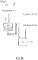
- FIG. 3a The course of a switching process is in the Figures 3a to 3d shown schematically.
- a first phase 1 which in Figure 3a
- the centrifugal system is rotating at a constant rotational frequency (eg, 5 Hz) at a first temperature (eg, 75°C).
- the potential difference cannot be overcome by the liquid and the liquid initially remains in the inlet chamber 20. This represents the first non-actuated state of the fluidic structures.
- a second phase 2 which is Figure 3b is shown, the temperature is lowered to eg 55°C.
- a rapid temperature decrease is assumed, for example a temperature decrease of ⁇ 0.1 K/s or of ⁇ 0.5 K/s.
- the thermal compression of the air in chambers 20 and 22 creates a pressure gradient between the environment (pressure p 0 ) and chambers 20 and 22, the course of which over time depends on the fluidic resistances of channels 24, 26 and 28 and the volumes of chambers 20 and 22 depends, the fluid channels and the chambers being designed in terms of their volumes or flow resistances such that the described functionality is achieved.
- Air for pressure equalization cannot be provided immediately through the ventilation channels, since both have a fluidic resistance (i.e. viscous dissipation takes place). This results in a pressure profile p1(t) in the outlet chamber 22 and a pressure profile p2(t) in the inlet chamber 20, which also results in a pressure difference from the inlet chamber 20 to the outlet chamber 22 due to the different flow resistances of the venting channels:
- the resulting pressure gradient over time is used to overcome the potential difference of the liquid between the chambers 20 and 22, ie to activate the switch.
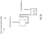
- the pressure difference between the chambers p1(t)-p2(t) due to the different dynamics of the pressure equalization leads to the liquid meniscus being drawn into the connecting channel 24 and over the apex of the siphon against the centrifugal force present. This then leads to the complete emptying of the inlet chamber 20 into the outlet chamber 22 with rotation, since the connecting channel 24 has an overall radial gradient. This phase 3 is in 3c shown.
- the brief pressure difference pulls the liquid against the centrifugal force into the connecting channel 24 and when the meniscus exceeds the apex (filling level in the inlet chamber 20), the inlet chamber 20 empties through an interaction of p1(t) - p2(t) and the then proportionally increasing centrifugal pressure.
- 3d shows the rotation frequency and the temperature during the three phases.
- the rotational frequency is constant during the three phases.
- a centrifuge can be used as the drive device, the rotational frequency of which does not have to be adjustable to different frequencies and the direction of rotation of which does not have to be reversible.
- the temperature is lowered in the second phase.
- Appropriate temperature control can be carried out by a heating/cooling device that is configured to heat or cool the entire rotating body or the entire fluidic module in which the fluidic structures are formed.
- a corresponding heating or cooling plate or radiant heating or cooling can be provided for this purpose.
- the outlet chamber 22 has the high flow resistance volume product (of at least 6700 N ⁇ s m 2 ) on.
- the fluidic structures differ from those in 2 Structures shown in that the inlet chamber 20 has the high flow resistance-volume product, for example by the flow resistances of the vent channels 26 and 28 are reversed.
- the flow resistance-volume product of the inlet chamber 20 would then be higher ( ⁇ 4 times) than the flow resistance-volume product of the outlet chamber 22 is equalized more slowly in the inlet chamber 20 than in the outlet chamber 22.
- a pressure difference is caused between the inlet chamber 20 and the outlet chamber 22, through which the siphon in the connecting channel can be overcome, so that the liquid from the inlet chamber 20 into the outlet chamber 22 is driven.
- FIG. 12 schematically shows fluidic structures in a centrifugal microfluidic system, which has a vented inlet chamber 50, a vented outlet chamber 52 and a connecting channel 54 which fluidly connects the inlet chamber 50 to the outlet chamber 52.
- the inlet chamber 50 is located further inward than the outlet chamber 52 radially to the center of rotation R, ie the connecting channel 54 has a radial gradient so that liquid can be driven centrifugally through the connecting channel 54 from the first chamber 50 into the second chamber 52 .
- the connecting channel 54 does not have a potential barrier in the form of a siphon.
- An inlet chamber ventilation channel 56 with the fluidic resistance R1 is coupled to the environment and opens into a radially inner area of the inlet chamber 50 and an outlet chamber ventilation channel 58 with the fluidic resistance R2 is coupled to the environment and opens into a radially inner area of the outlet chamber 52.
- the connecting channel 54 which has a fluidic resistance R3, opens into a radially outer region of the inlet chamber 50 and into a radially inner region of the outlet chamber 52.
- the flow resistance-volume product of the outlet chamber 52 is at least 6700 N ⁇ s m 2 .
- the fluidic resistances the following applies: R1 ⁇ R2 and R3 ⁇ R2, so that a flow resistance-volume product of the outlet chamber 52 is greater than or equal to four times the flow resistance-volume product of the inlet chamber 50.
- the fluidic structures can be rotated around a center of rotation R. Positions corresponding to points A and B in Fig. 1a correspond, are in Figure 4a represented by dashed arrows.
- the outlet chamber 52 is filled with air as an example of a compressible medium.
- the inlet chamber 50 is partially filled with a liquid and partially with a volume of air.
- the inlet chamber 50 could also be completely filled with the liquid.
- a first phase 1 let the pressure in the liquid in the inlet chamber 50 and the air pressure in the inlet chamber 50 and the outlet chamber 52 be equal to the ambient pressure.
- the fluidic structures can be stationary during the first phase, ie not subjected to any rotation.
- surface tension of the liquid may prevent it from entering the connection channel 54 or from the connection channel 54 into the outlet chamber 52 .
- a second phase 2 which in Figure 4b is shown, the system is accelerated to a rotation of, for example, 5 Hz in a short time.
- the centrifugal force acts on the liquid and a pumping mechanism is initiated by the resulting centrifugal pressure.
- the liquid flows through the connecting channel 54 and into the outlet chamber 52 at a specific volumetric flow rate S1 and thereby compresses the air volume in the outlet chamber by ⁇ V.
- the resulting pressure gradient to the environment means that air flows into the environment via the outlet chamber ventilation channel with a specific volume flow S2.
- the resulting volume flows S1 and S2 are dependent on p1(t) and thus on R2.
- the flow rate can be regulated by adjusting the resistor R2 to realize a delay in pumping, for example. It is thus possible to regulate the flow rate and thus the delay in emptying the inlet chamber into the outlet chamber via the selection of the fluidic resistances, in particular the ventilation channels.
- the total drag may be equal to or greater than a factor times that Total fluid resistance, where the factor can be 4.
- the total air resistance is the resistance presented to the air to escape from the outlet chamber and the total liquid resistance is the resistance presented to the liquid to flow into the outlet chamber.
- the inlet chamber 50 can have the high flow resistance-volume product, for example by the flow resistances of the ventilation channels 56 and 58 being reversed.
- a negative pressure is generated, which counteracts the centrifugal force acting on the liquid and thus throttles a flow of the liquid through the connecting channel 54 from the inlet chamber 50 into the outlet chamber 52.
- the flow resistance of the connecting channel with respect to the liquid can be much lower than the flow resistance of the venting channel of the fluid chamber with the high flow resistance-volume product with respect to the compressible medium.
- the flow resistance of the connecting channel can be considered negligible in these cases.
- the flow resistance of the connecting channel with respect to the liquid can also be greater than the flow resistance of the venting channel of the fluid chamber with the high flow resistance-volume product with respect to the compressible medium.
- Figure 5a 14 shows an embodiment in which the flow resistance of the connecting channel 14a with respect to the liquid is adapted in order to enable a (multiple) transfer of a partial liquid volume.
- a flow takes place from the inlet chamber 50 into the outlet chamber 52 until an underpressure existing in the outlet chamber 52 or an overpressure existing in the inlet chamber 50 has been compensated.
- the flow comes to a standstill, with residual liquid being able to remain in the inlet chamber 50 .
- This process can be repeated if necessary.
- the volume of liquid to be transferred can be set via the negative pressure or positive pressure. Thus, repeated transfer of defined sub-volumes is possible.
- Figure 5b shows a device in which the flow resistance of the connecting channel 14b is adjusted with respect to the liquid in order to delay a transfer To realize liquid from the inlet chamber 20 into the outlet chamber 22.
- the connection channel 14b contains a siphon valve with a downstream flow resistance. Initially, a wide range of rotational frequencies can be used without liquid being transferred from the inlet chamber 20 to the outlet chamber 22 . This transfer is prevented by the siphon valve.
- the siphon valve channel can be wetted by the subsequent negative pressure in the outlet chamber 22 or positive pressure in the inlet chamber 20 . However, there is still no liquid transfer from the inlet chamber 20 into the outlet chamber 22 . Subsequently, an emptying of the liquid from the inlet chamber into the outlet chamber can be controlled by increasing the rotational frequency.
- liquids can be switched sequentially into the outlet chamber by the liquid from the second inlet chamber being pumped out of the second inlet chamber with negative pressure in the outlet chamber 22 or positive pressure in the Inlet chambers is transferred directly and the liquid from the first inlet chamber 20 only after a rotational frequency increase.
- the connecting channel can thus consist of a number of segments, for example a first section with a low flow resistance and a second section with a high flow resistance with respect to the liquid.
- the different flow resistance-volume products are essentially implemented by different flow resistances of the ventilation channels.
- the different products can alternatively or additionally be achieved by different volumes.
- the ventilation channels can have essentially the same flow resistance and the volume of one chamber can be at least four times the volume of the other chamber.
- both flow resistances and chamber volumes can be different in order to obtain an appropriate relationship between the products.
- inlet chambers can be provided, which are fluidically connected to the outlet chamber via connecting channels.
- the connecting channels can open into a common connecting channel, which opens into the outlet chamber.
- the inlet chambers, the connecting channels and the outlet chamber can be designed to achieve the described effects with regard to the multiple inlet chambers and the outlet chamber.
- Embodiments of the invention can be used in particular in the field of centrifugal microfluidics, which involves the processing of liquids in the femtoliter to milliliter range.
- the fluidic structures can have suitable dimensions in the micrometer range for handling corresponding volumes of liquid.
- exemplary embodiments of the invention can be used on centrifugal microfluidic systems, such as are known, for example, under the name “lab-on-a-disk”.
- radial in each case radially in relation to the center of rotation R, about which a body of revolution can be rotated.
- a radial direction away from the center of rotation is thus radially decreasing and a radial direction towards the center of rotation is radially increasing.
- a fluid channel whose beginning is closer to the center of rotation than its end is thus radially descending, while a fluid channel whose beginning is further from the center of rotation than its end is radially ascending.
- a channel that has a radially rising section therefore has directional components that rise radially or run radially inwards. It is clear that such a channel does not have to run exactly along a radial line, but can run at an angle to the radial line or curved.
- different flow resistances (fluidic resistances, hydraulic resistances) of the respective fluid channels can be achieved via different flow cross sections.
- different flow resistances can also be achieved by other means, for example different channel lengths, obstacles integrated into the channels and the like. If a comparison between flow resistances is given, the flow resistance in relation to the same fluid is to be assumed in each case, unless otherwise stated.
- a fluid channel is mentioned herein, a structure is meant whose length dimension from a fluid inlet to a fluid outlet is greater, for example more than 5 times or more than 10 times greater than the dimension or dimensions that define the flow cross section or define.
- a fluid channel can thus have a flow resistance for flowing through it from the fluid inlet to the fluid outlet.
- a fluid chamber here is a chamber that can have such dimensions that a relevant flow resistance does not occur in it.
- liquid or liquid phase as used herein also includes liquids containing solid components such as suspensions and biological samples.
- FIG. 1 shows a device with a fluidic module 110 in the form of a body of revolution, which has a substrate 112 and a cover 114 .
- the substrate 112 and cover 114 may be circular in plan view, with a central opening through which the body of revolution 110 may be attached to a rotating part 118 of a drive device 120 via a conventional fastener 116 .
- the rotating part 118 is rotatably mounted on a stationary part 122 of the drive device 120 .
- the drive device 120 can be, for example, a conventional centrifuge, which can have an adjustable rotational speed, or a CD or DVD drive.
- a control device 124 can be provided, which is designed to control the drive device 120 in order to apply a rotation or rotations of different rotational frequencies to the rotating body 110 .
- the controller 124 may be implemented, for example, by an appropriately programmed computing device or a custom integrated circuit, as will be appreciated by those skilled in the art.
- the control device 124 can also be designed to control the drive device 120 in response to manual inputs by a user in order to bring about the required rotations of the rotary body.
- the controller 124 may be configured to control the drive device 120 to impart the required rotation to the rotating body in order to implement embodiments of the invention as described herein.
- a conventional centrifuge with only one direction of rotation can be used as drive device 120 .
- the body of revolution 110 has the required fluidic structures.
- the required fluidic structures can be formed by cavities and channels in the cover 114, the substrate 112 or in the substrate 112 and the cover 114.
- fluidic structures may be imaged in the substrate 112 while fill ports and vent ports are formed in the lid 114 .
- the structured substrate (including filling openings and ventilation openings) can be arranged at the top and the lid arranged at the bottom.
- fluidic modules 132 used in a rotor 130 and together with the rotor 130 form the rotating body 110.
- the fluidic modules 132 can each have a substrate and a cover, in which in turn corresponding fluidic structures can be formed.
- the rotary body 110 formed by the rotor 130 and the fluidic modules 132 can in turn be subjected to a rotation by a drive device 120 which is controlled by the control device 124 .
- the fluidic module or the rotary body which has the fluidic structures can be made of any suitable material, for example a plastic such as PMMA (polymethyl methacrylate), PC (polycarbonate), PVC (polyvinyl chloride) or PDMS (polydimethylsiloxane), glass or similar.
- the body of revolution 110 can be viewed as a centrifugal microfluidic platform.
- the fluidics module the rotary body can be formed from a thermoplastic such as PP (polypropylene), PC, COP (cyclic olefin polymer), COC (cyclo olefin copolymer) or PS (polystyrene).
- a switching mechanism is implemented that can be operated at a constant rotational frequency. Activation of the switch can be adjusted by choice of fluid resistance, fluid viscosity, heating/cooling rate, and rotational frequency.
- the relationship between the flow resistance-volume products corresponding to the respective resistances for the same fluid, such as air, can be determined.
- the principle of dynamic venting can also be used for a Delay function can be used.
- flow of a first fluid with a high viscosity (such as water) into a vented chamber for a second fluid with a low viscosity (such as air) can be affected by the fluidic resistance of the vent passages, with flow of the first fluid into the Chamber can be minimized.
- the volume flows are significant at low rotational speeds more precisely adjustable, and there is no risk of bubbles or plugs forming in the fluidic channel for the high-viscosity fluid.
- the underlying principle can be used for both highly wetting and non-wetting liquids.
- the underlying principle can also be used for higher-viscosity liquids by suitably selecting the fluidic resistances in the system.
- a switching principle according to the invention is not based on capillary pressures, which dominate centrifugal pressures below a switching frequency.
- the switching principle is therefore not only applicable to liquid-material combinations where a contact angle ⁇ 90 results, so that such an angle does not have to be created by adding additives to the liquid or by surface coating, which may not be compatible with the (biochemical) to be integrated Processes is compatible or construction and connection costs (AVT) of the system significantly increased.
- exemplary embodiments of the invention do not require a variable rotational speed, which may not be the case with all processing devices.
- the switching principle according to the invention does not require a terminal, closed volume of air, so that integration as the last switching process in a fluidic network is not required.
- variable rotational speeds are necessary with centrifugal-pneumatic valves, which is not necessary according to the invention.
- the invention does not require variable rotational speeds, nor does the liquid need to be suitable for dissolving a water-soluble membrane. It can thus be prevented that possible solution products of the membrane are mixed with the liquid. Increased AVT costs, such as are required with such dissolvable membranes in order not to be dependent on a terminal chamber, can be avoided with embodiments of the invention.
- a significantly reduced effort is also possible according to the invention compared to time-controlled valves, as described in [5].
- the switching principle is functional with such time-controlled valves at a constant rotational speed, the switching times are defined by the dimensioning of the paper strip and the dissolution behavior of the membranes and do not allow subsequent adaptation, e.g. by changing the temperature profile.
- the switching principle requires an additional auxiliary liquid, which must either be stored in advance or added by the user. Such measures are not necessary according to the invention.
- the switching principle requires a manufacturing process in which molten paraffin wax is positioned with pinpoint accuracy, hardened and the disk can then be further processed, so that the AVT costs are significantly increased.
- the switch actuation requires a local heating source that can melt the paraffin wax (active switch), which increases the complexity of the processing device.
- the switch is not robust against high centrifugal pressures, which may be required by the application (e.g. blood plasma separation).
- the switch can only be used with closed air volumes, so that it cannot be freely integrated into fluidic networks. Compared to such valves, too, the invention clearly enables a less complex method and more flexible use.
- thermo-pneumatic valves as known from [8] the switching principle requires a large, separate volume of air, which consumes valuable space on the limited disc.
- a closed volume of air is necessary, so that the valve cannot be freely integrated into fluidic networks.
- the processing device must allow for local heating, making it more complex and expensive. Compared to such valves, the invention also enables a significantly less complex method and more flexible use.
- the outlet chamber vent channel may have a cross section of 100 ⁇ m by 100 ⁇ m with a length of 30 mm.
- the volume of the outlet chamber can be 900 ⁇ l
- the volume of the inlet chamber can be 500 ⁇ l.
- the connecting channel can have a cross section of 300 ⁇ m by 300 ⁇ m with a length of 10 mm.
- the inlet chamber ventilation duct may have a cross section of 600 ⁇ m by 600 ⁇ m with a length of 30 mm.
- can be greater than 5 mbar.
- the outlet chamber vent channel may have a cross section of 50 microns by 50 microns with a length of 30 mm.
- the volume of the outlet chamber can be 900 ⁇ l, the volume of the inlet chamber can be 500 ⁇ l.
- the connecting channel can have a cross section of 300 ⁇ m by 300 ⁇ m with a length of 10 mm.
- the inlet chamber ventilation duct may have a cross section of 600 ⁇ m by 600 ⁇ m with a length of 30 mm.
- a switching mechanism is thus created which is determined by the dimensions of the chambers and by the fluid resistances of the channels as a result of a change in temperature.
- a switching mechanism triggered by the dynamics of fluid equalization processes due to a local or global volume change or pressure change can be implemented at a constant rotational frequency.
- a flow rate through a first fluid from an inlet chamber into an outlet chamber can be adjusted by selecting the volumes of the chambers and the fluid resistances are influenced in order to realize a delay switch.
Landscapes
- Chemical & Material Sciences (AREA)
- General Engineering & Computer Science (AREA)
- Engineering & Computer Science (AREA)
- Dispersion Chemistry (AREA)
- Health & Medical Sciences (AREA)
- Mechanical Engineering (AREA)
- Chemical Kinetics & Catalysis (AREA)
- Analytical Chemistry (AREA)
- General Health & Medical Sciences (AREA)
- Hematology (AREA)
- Clinical Laboratory Science (AREA)
- Automatic Analysis And Handling Materials Therefor (AREA)
- Jet Pumps And Other Pumps (AREA)
- External Artificial Organs (AREA)
Applications Claiming Priority (2)
| Application Number | Priority Date | Filing Date | Title |
|---|---|---|---|
| DE102016207845.3A DE102016207845B4 (de) | 2016-05-06 | 2016-05-06 | Fluidhandhabungsvorrichtung und Verfahren zur Fluidhandhabung |
| PCT/EP2017/060075 WO2017191032A1 (de) | 2016-05-06 | 2017-04-27 | Fluidhandhabungsvorrichtung und verfahren zur fluidhandhabung |
Publications (2)
| Publication Number | Publication Date |
|---|---|
| EP3452217A1 EP3452217A1 (de) | 2019-03-13 |
| EP3452217B1 true EP3452217B1 (de) | 2022-07-20 |
Family
ID=58633007
Family Applications (1)
| Application Number | Title | Priority Date | Filing Date |
|---|---|---|---|
| EP17719615.1A Active EP3452217B1 (de) | 2016-05-06 | 2017-04-27 | Fluidhandhabungsvorrichtung und verfahren zur fluidhandhabung |
Country Status (7)
| Country | Link |
|---|---|
| US (1) | US10906041B2 (pl) |
| EP (1) | EP3452217B1 (pl) |
| CN (1) | CN109641208B (pl) |
| DE (1) | DE102016207845B4 (pl) |
| ES (1) | ES2927095T3 (pl) |
| PL (1) | PL3452217T3 (pl) |
| WO (1) | WO2017191032A1 (pl) |
Families Citing this family (14)
| Publication number | Priority date | Publication date | Assignee | Title |
|---|---|---|---|---|
| DE102012202775B4 (de) * | 2012-02-23 | 2016-08-25 | Hahn-Schickard-Gesellschaft für angewandte Forschung e.V. | Fluidikmodul, vorrichtung und verfahren zum pumpen einer flüssigkeit |
| DE102016207845B4 (de) * | 2016-05-06 | 2018-04-12 | Hahn-Schickard-Gesellschaft für angewandte Forschung e.V. | Fluidhandhabungsvorrichtung und Verfahren zur Fluidhandhabung |
| DE102016121764B4 (de) * | 2016-11-14 | 2026-02-12 | Testo SE & Co. KGaA | Mikrofluidische Verarbeitungskammer, Testträger und zugehöriges Verfahren zur Prozessierung einer Flüssigkeit in einem Testträger |
| DE102017204002B4 (de) | 2017-03-10 | 2019-05-23 | Hahn-Schickard-Gesellschaft für angewandte Forschung e.V. | Zentrifugo-pneumatisches schalten von flüssigkeit |
| CA3133632A1 (en) | 2019-03-19 | 2020-09-24 | Monika Ursula Helga Bruggemann | Means and methods for accurately assessing clonal immunoglobulin (ig)/t cell receptor (tr) gene rearrangements. |
| CN109894175B (zh) * | 2019-04-11 | 2024-05-17 | 石家庄禾柏生物技术股份有限公司 | 一种流体控制模块 |
| CN110227564B (zh) * | 2019-06-17 | 2021-07-02 | 佛山市麦控智能科技有限公司 | 基于微流控技术的检测系统 |
| US12023689B2 (en) * | 2020-04-24 | 2024-07-02 | Quommni Technologies Limited | Fluidics device, apparatus, and method for partitioning fluid |
| DE102020207628B4 (de) | 2020-06-19 | 2023-01-19 | Hahn-Schickard-Gesellschaft für angewandte Forschung e.V. | Leiten eines flüssigkeitsflusses auf eine aktive festphase |
| DE102021208891B3 (de) | 2021-08-13 | 2022-10-13 | Hahn-Schickard-Gesellschaft für angewandte Forschung e.V. | Unterdruckschalten von Flüssigkeit |
| DE102021133494B4 (de) * | 2021-12-16 | 2024-02-29 | Dermagnostix GmbH | Centrifugal Microfluidic Biochip |
| DE102023202206A1 (de) | 2023-03-10 | 2024-09-12 | Hahn-Schickard-Gesellschaft für angewandte Forschung e.V. | Sequentielles Pumpen mittels eines Aktuators |
| US12320723B2 (en) * | 2023-03-31 | 2025-06-03 | Ametek, Inc. | Apparatus for measurement of capillary pressure in a porous sample |
| CN120861186B (zh) * | 2025-09-28 | 2025-12-16 | 甬江实验室 | 微流控芯片的外部灌流系统及液路控制方法 |
Citations (1)
| Publication number | Priority date | Publication date | Assignee | Title |
|---|---|---|---|---|
| DE202011108189U1 (de) * | 2011-06-08 | 2011-12-13 | Albert-Ludwigs-Universität Freiburg | Vorrichtung und Fluidikmodul zum Erzeugen einer Verdünnungsreihe |
Family Cites Families (22)
| Publication number | Priority date | Publication date | Assignee | Title |
|---|---|---|---|---|
| US20030198576A1 (en) * | 2002-02-22 | 2003-10-23 | Nanostream, Inc. | Ratiometric dilution devices and methods |
| US20060028908A1 (en) * | 2004-08-03 | 2006-02-09 | Suriadi Arief B | Micro-mixer |
| EP1869158B1 (en) * | 2005-03-22 | 2013-05-29 | Life Technologies Corporation | Pressure chamber clamp mechanism |
| US20060281192A1 (en) * | 2005-06-13 | 2006-12-14 | Harding Philip H | Method for mixing fluids in microfluidic systems |
| DE102005048233A1 (de) * | 2005-10-07 | 2007-04-12 | Albert-Ludwigs-Universität Freiburg | Vorrichtung und Verfahren zum Handhaben einer flüssigen Probe unter Verwendung einer Siphon-Struktur |
| KR101228112B1 (ko) * | 2006-12-06 | 2013-01-31 | 삼성전자주식회사 | 원심력과 펌프를 이용해 유체의 이동을 제어하는 미세유동장치 및 이를 포함하는 미세유동 시스템 |
| AU2007336774A1 (en) | 2006-12-22 | 2008-07-03 | 3M Innovative Properties Company | Thermal transfer methods and structures for microfluidic systems |
| JP5013423B2 (ja) * | 2007-10-18 | 2012-08-29 | ローム株式会社 | マイクロチップ |
| CN101850231B (zh) * | 2009-07-03 | 2012-08-29 | 中国科学院上海微系统与信息技术研究所 | 一种微流体反应器、使用方法及其应用 |
| DE102009050979B4 (de) * | 2009-10-28 | 2011-09-22 | Hahn-Schickard-Gesellschaft für angewandte Forschung e.V. | Vorrichtung und Verfahren zum Steuern eines Flüssigkeitsflusses und Vorrichtung zum Verschließen eines Entlüftungskanals |
| EP2455162A1 (de) * | 2010-10-29 | 2012-05-23 | Roche Diagnostics GmbH | Mikrofluidisches Element zur Analyse einer Probenflüssigkeit |
| DE102011083920B4 (de) | 2011-09-30 | 2018-07-19 | Albert-Ludwigs-Universität Freiburg | Verfahren und vorrichtung zum erzeugen von fluidisch voneinander separierten teilvolumina einer flüssigkeit |
| DE102012202775B4 (de) * | 2012-02-23 | 2016-08-25 | Hahn-Schickard-Gesellschaft für angewandte Forschung e.V. | Fluidikmodul, vorrichtung und verfahren zum pumpen einer flüssigkeit |
| DE102013203293B4 (de) | 2013-02-27 | 2016-01-21 | Hahn-Schickard-Gesellschaft für angewandte Forschung e.V. | Vorrichtung und Verfahren zum Leiten einer Flüssigkeit durch einen ersten oder zweiten Auslasskanal |
| DE102013210818B3 (de) * | 2013-06-10 | 2014-05-15 | Hahn-Schickard-Gesellschaft für angewandte Forschung e.V. | Fluidhandhabungsvorrichtung und Verfahren zum Prozessieren einer Flüssigkeit unter Verwendung einer Diffusionsbarriere |
| DE102013215002B3 (de) | 2013-07-31 | 2014-11-06 | Hahn-Schickard-Gesellschaft für angewandte Forschung e.V. | Vorrichtung und Verfahren zum Bewegen von Flüssigkeit in einem zentrifugalen System unter Verwendung von Unterdruck |
| DE102013218978B3 (de) * | 2013-09-20 | 2014-11-06 | Hahn-Schickard-Gesellschaft für angewandte Forschung e.V. | Vorrichtung und Verfahren, die Rückschlüsse über die Viskosität einer Probe ermöglichen |
| DE102013220257B3 (de) * | 2013-10-08 | 2015-02-19 | Hahn-Schickard-Gesellschaft für angewandte Forschung e.V. | Vorrichtung und verfahren zur durchmischung zumindest einer flüssigkeit |
| CN103706413B (zh) * | 2013-12-18 | 2015-12-30 | 上海交通大学 | 微流控相变汽泡微泵阀及其方法 |
| DE102014211121A1 (de) * | 2014-06-11 | 2015-12-17 | Hahn-Schickard-Gesellschaft für angewandte Forschung e.V. | Fluidikmodul, vorrichtung und verfahren zum handhaben von flüssigkeit |
| DE102016207845B4 (de) * | 2016-05-06 | 2018-04-12 | Hahn-Schickard-Gesellschaft für angewandte Forschung e.V. | Fluidhandhabungsvorrichtung und Verfahren zur Fluidhandhabung |
| DE102016208972A1 (de) * | 2016-05-24 | 2017-11-30 | Hahn-Schickard-Gesellschaft für angewandte Forschung e.V. | Fluidikmodul, Vorrichtung und Verfahren zum biochemischen Prozessieren einer Flüssigkeit unter Verwendung von mehreren Temperaturzonen |
-
2016
- 2016-05-06 DE DE102016207845.3A patent/DE102016207845B4/de active Active
-
2017
- 2017-04-27 WO PCT/EP2017/060075 patent/WO2017191032A1/de not_active Ceased
- 2017-04-27 ES ES17719615T patent/ES2927095T3/es active Active
- 2017-04-27 EP EP17719615.1A patent/EP3452217B1/de active Active
- 2017-04-27 PL PL17719615.1T patent/PL3452217T3/pl unknown
- 2017-04-27 CN CN201780041477.6A patent/CN109641208B/zh active Active
-
2018
- 2018-11-05 US US16/181,043 patent/US10906041B2/en active Active
Patent Citations (1)
| Publication number | Priority date | Publication date | Assignee | Title |
|---|---|---|---|---|
| DE202011108189U1 (de) * | 2011-06-08 | 2011-12-13 | Albert-Ludwigs-Universität Freiburg | Vorrichtung und Fluidikmodul zum Erzeugen einer Verdünnungsreihe |
Non-Patent Citations (2)
| Title |
|---|
| HUTZENLAUB T ET AL: "The effect of wetting properties on bubble dynamics and fuel distribution in the flow field of direct methanol fuel cells", JOURNAL OF POWER SOURCES, ELSEVIER, AMSTERDAM, NL, vol. 196, no. 19, 25 May 2011 (2011-05-25), pages 8048 - 8056, XP028241168, ISSN: 0378-7753, [retrieved on 20110601], DOI: 10.1016/J.JPOWSOUR.2011.05.070 * |
| RICHTER ET AL: "Microchannels for applications in liquid dosing and flow-rate measurement", SENSORS AND ACTUATORS A: PHYSICAL, ELSEVIER BV, NL, vol. 62, no. 1-3, 1 July 1997 (1997-07-01), pages 480 - 483, XP022542055, ISSN: 0924-4247, DOI: 10.1016/S0924-4247(97)01486-6 * |
Also Published As
| Publication number | Publication date |
|---|---|
| PL3452217T3 (pl) | 2022-11-21 |
| WO2017191032A1 (de) | 2017-11-09 |
| DE102016207845B4 (de) | 2018-04-12 |
| US20190070607A1 (en) | 2019-03-07 |
| ES2927095T3 (es) | 2022-11-02 |
| CN109641208A (zh) | 2019-04-16 |
| US10906041B2 (en) | 2021-02-02 |
| DE102016207845A1 (de) | 2017-11-09 |
| EP3452217A1 (de) | 2019-03-13 |
| CN109641208B (zh) | 2021-11-09 |
Similar Documents
| Publication | Publication Date | Title |
|---|---|---|
| EP3452217B1 (de) | Fluidhandhabungsvorrichtung und verfahren zur fluidhandhabung | |
| DE102013203293B4 (de) | Vorrichtung und Verfahren zum Leiten einer Flüssigkeit durch einen ersten oder zweiten Auslasskanal | |
| DE102017204002B4 (de) | Zentrifugo-pneumatisches schalten von flüssigkeit | |
| DE102012202775B4 (de) | Fluidikmodul, vorrichtung und verfahren zum pumpen einer flüssigkeit | |
| DE102008003979B3 (de) | Fluidikvorrichtung, Fluidikmodul und Verfahren zum Handhaben einer Flüssigkeit | |
| EP3227023B1 (de) | Verfahren zur tropfenerzeugung | |
| DE102011083920B4 (de) | Verfahren und vorrichtung zum erzeugen von fluidisch voneinander separierten teilvolumina einer flüssigkeit | |
| DE102013215002B3 (de) | Vorrichtung und Verfahren zum Bewegen von Flüssigkeit in einem zentrifugalen System unter Verwendung von Unterdruck | |
| DE102013219929A1 (de) | Fluidikmodul, Vorrichtung und Verfahren zum Aliquotieren einer Flüssigkeit | |
| EP3154692B1 (de) | Fluidikmodul, vorrichtung und verfahren zum handhaben von flüssigkeit | |
| DE112018007590B3 (de) | Anwendungsspezifisch ausgestaltbare mikrofluidik-einheit mit programmierbaren mikrofluidik-knoten | |
| DE102009001257A1 (de) | Vorrichtung und Verfahren zur Handhabung von Flüssigkeiten | |
| DE102013210818B3 (de) | Fluidhandhabungsvorrichtung und Verfahren zum Prozessieren einer Flüssigkeit unter Verwendung einer Diffusionsbarriere | |
| DE102009050979B4 (de) | Vorrichtung und Verfahren zum Steuern eines Flüssigkeitsflusses und Vorrichtung zum Verschließen eines Entlüftungskanals | |
| DE102019209746A1 (de) | Mikrofluidische Vorrichtung zum Prozessieren und Aliquotieren einer Probenflüssigkeit, Verfahren und Steuergerät zum Betreiben einer mikrofluidischen Vorrichtung und mikrofluidisches System zum Durchführen einer Analyse einer Probenflüssigkeit | |
| WO2023016923A1 (de) | Unterdruckschalten von flüssigkeit | |
| EP3946732A1 (de) | Mikrotropfenrückhalteanordnung | |
| DE102021207014A1 (de) | Mikrofluidische Vorrichtung und Verfahren zum Betreiben einer mikrofluidischen Vorrichtung | |
| DE102023207560B3 (de) | Halten und Transferieren von Flüssigkeiten | |
| DE102020207628B4 (de) | Leiten eines flüssigkeitsflusses auf eine aktive festphase | |
| DE102023202206A1 (de) | Sequentielles Pumpen mittels eines Aktuators | |
| DE102023205997A1 (de) | Fluidikmodul und verfahren zur erzeugung räumlich separierter flüssigkeitspartitionen | |
| WO2024194145A1 (de) | Fluidikmodul, fluidhandhabungsvorrichtung und verfahren mit vorübergehendem druckausgleich in einer pneumatikkammer | |
| WO2021013595A1 (de) | Lab-on-chip-system mit mindestens einem funktionalisierten abschnitt | |
| KR20220043369A (ko) | 터치버튼 작동방식의 미세유체 기반 미세액적 생성기 |
Legal Events
| Date | Code | Title | Description |
|---|---|---|---|
| STAA | Information on the status of an ep patent application or granted ep patent |
Free format text: STATUS: UNKNOWN |
|
| STAA | Information on the status of an ep patent application or granted ep patent |
Free format text: STATUS: THE INTERNATIONAL PUBLICATION HAS BEEN MADE |
|
| PUAI | Public reference made under article 153(3) epc to a published international application that has entered the european phase |
Free format text: ORIGINAL CODE: 0009012 |
|
| STAA | Information on the status of an ep patent application or granted ep patent |
Free format text: STATUS: REQUEST FOR EXAMINATION WAS MADE |
|
| 17P | Request for examination filed |
Effective date: 20181122 |
|
| AK | Designated contracting states |
Kind code of ref document: A1 Designated state(s): AL AT BE BG CH CY CZ DE DK EE ES FI FR GB GR HR HU IE IS IT LI LT LU LV MC MK MT NL NO PL PT RO RS SE SI SK SM TR |
|
| AX | Request for extension of the european patent |
Extension state: BA ME |
|
| RIN1 | Information on inventor provided before grant (corrected) |
Inventor name: HUTZENLAUB, TOBIAS Inventor name: KELLER, MARC Inventor name: PAUST, NILS Inventor name: CZILWIK, GREGOR |
|
| RIN1 | Information on inventor provided before grant (corrected) |
Inventor name: HUTZENLAUB, TOBIAS Inventor name: KELLER, MARK Inventor name: CZILWIK, GREGOR Inventor name: PAUST, NILS |
|
| DAV | Request for validation of the european patent (deleted) | ||
| DAX | Request for extension of the european patent (deleted) | ||
| STAA | Information on the status of an ep patent application or granted ep patent |
Free format text: STATUS: EXAMINATION IS IN PROGRESS |
|
| 17Q | First examination report despatched |
Effective date: 20200417 |
|
| GRAP | Despatch of communication of intention to grant a patent |
Free format text: ORIGINAL CODE: EPIDOSNIGR1 |
|
| STAA | Information on the status of an ep patent application or granted ep patent |
Free format text: STATUS: GRANT OF PATENT IS INTENDED |
|
| INTG | Intention to grant announced |
Effective date: 20220207 |
|
| GRAS | Grant fee paid |
Free format text: ORIGINAL CODE: EPIDOSNIGR3 |
|
| GRAA | (expected) grant |
Free format text: ORIGINAL CODE: 0009210 |
|
| STAA | Information on the status of an ep patent application or granted ep patent |
Free format text: STATUS: THE PATENT HAS BEEN GRANTED |
|
| AK | Designated contracting states |
Kind code of ref document: B1 Designated state(s): AL AT BE BG CH CY CZ DK EE ES FI FR GB GR HR HU IE IS IT LI LT LU LV MC MK MT NL NO PL PT RO RS SE SI SK SM TR |
|
| RBV | Designated contracting states (corrected) |
Designated state(s): AL AT BE BG CH CY CZ DK EE ES FI FR GB GR HR HU IE IS IT LI LT LU LV MC MK MT NL NO PL PT RO RS SE SI SK SM TR |
|
| REG | Reference to a national code |
Ref country code: DE Ref legal event code: R108 |
|
| REG | Reference to a national code |
Ref country code: CH Ref legal event code: EP |
|
| REG | Reference to a national code |
Ref country code: AT Ref legal event code: REF Ref document number: 1505183 Country of ref document: AT Kind code of ref document: T Effective date: 20220815 |
|
| REG | Reference to a national code |
Ref country code: IE Ref legal event code: FG4D Free format text: LANGUAGE OF EP DOCUMENT: GERMAN |
|
| REG | Reference to a national code |
Ref country code: NL Ref legal event code: FP |
|
| REG | Reference to a national code |
Ref country code: ES Ref legal event code: FG2A Ref document number: 2927095 Country of ref document: ES Kind code of ref document: T3 Effective date: 20221102 |
|
| REG | Reference to a national code |
Ref country code: SE Ref legal event code: TRGR |
|
| REG | Reference to a national code |
Ref country code: LT Ref legal event code: MG9D |
|
| REG | Reference to a national code |
Ref country code: NO Ref legal event code: T2 Effective date: 20220720 |
|
| PG25 | Lapsed in a contracting state [announced via postgrant information from national office to epo] |
Ref country code: RS Free format text: LAPSE BECAUSE OF FAILURE TO SUBMIT A TRANSLATION OF THE DESCRIPTION OR TO PAY THE FEE WITHIN THE PRESCRIBED TIME-LIMIT Effective date: 20220720 Ref country code: PT Free format text: LAPSE BECAUSE OF FAILURE TO SUBMIT A TRANSLATION OF THE DESCRIPTION OR TO PAY THE FEE WITHIN THE PRESCRIBED TIME-LIMIT Effective date: 20221121 Ref country code: LV Free format text: LAPSE BECAUSE OF FAILURE TO SUBMIT A TRANSLATION OF THE DESCRIPTION OR TO PAY THE FEE WITHIN THE PRESCRIBED TIME-LIMIT Effective date: 20220720 Ref country code: LT Free format text: LAPSE BECAUSE OF FAILURE TO SUBMIT A TRANSLATION OF THE DESCRIPTION OR TO PAY THE FEE WITHIN THE PRESCRIBED TIME-LIMIT Effective date: 20220720 Ref country code: FI Free format text: LAPSE BECAUSE OF FAILURE TO SUBMIT A TRANSLATION OF THE DESCRIPTION OR TO PAY THE FEE WITHIN THE PRESCRIBED TIME-LIMIT Effective date: 20220720 |
|
| PG25 | Lapsed in a contracting state [announced via postgrant information from national office to epo] |
Ref country code: IS Free format text: LAPSE BECAUSE OF FAILURE TO SUBMIT A TRANSLATION OF THE DESCRIPTION OR TO PAY THE FEE WITHIN THE PRESCRIBED TIME-LIMIT Effective date: 20221120 Ref country code: HR Free format text: LAPSE BECAUSE OF FAILURE TO SUBMIT A TRANSLATION OF THE DESCRIPTION OR TO PAY THE FEE WITHIN THE PRESCRIBED TIME-LIMIT Effective date: 20220720 Ref country code: GR Free format text: LAPSE BECAUSE OF FAILURE TO SUBMIT A TRANSLATION OF THE DESCRIPTION OR TO PAY THE FEE WITHIN THE PRESCRIBED TIME-LIMIT Effective date: 20221021 |
|
| PG25 | Lapsed in a contracting state [announced via postgrant information from national office to epo] |
Ref country code: SM Free format text: LAPSE BECAUSE OF FAILURE TO SUBMIT A TRANSLATION OF THE DESCRIPTION OR TO PAY THE FEE WITHIN THE PRESCRIBED TIME-LIMIT Effective date: 20220720 Ref country code: RO Free format text: LAPSE BECAUSE OF FAILURE TO SUBMIT A TRANSLATION OF THE DESCRIPTION OR TO PAY THE FEE WITHIN THE PRESCRIBED TIME-LIMIT Effective date: 20220720 Ref country code: DK Free format text: LAPSE BECAUSE OF FAILURE TO SUBMIT A TRANSLATION OF THE DESCRIPTION OR TO PAY THE FEE WITHIN THE PRESCRIBED TIME-LIMIT Effective date: 20220720 Ref country code: CZ Free format text: LAPSE BECAUSE OF FAILURE TO SUBMIT A TRANSLATION OF THE DESCRIPTION OR TO PAY THE FEE WITHIN THE PRESCRIBED TIME-LIMIT Effective date: 20220720 |
|
| PLBE | No opposition filed within time limit |
Free format text: ORIGINAL CODE: 0009261 |
|
| STAA | Information on the status of an ep patent application or granted ep patent |
Free format text: STATUS: NO OPPOSITION FILED WITHIN TIME LIMIT |
|
| PG25 | Lapsed in a contracting state [announced via postgrant information from national office to epo] |
Ref country code: SK Free format text: LAPSE BECAUSE OF FAILURE TO SUBMIT A TRANSLATION OF THE DESCRIPTION OR TO PAY THE FEE WITHIN THE PRESCRIBED TIME-LIMIT Effective date: 20220720 Ref country code: EE Free format text: LAPSE BECAUSE OF FAILURE TO SUBMIT A TRANSLATION OF THE DESCRIPTION OR TO PAY THE FEE WITHIN THE PRESCRIBED TIME-LIMIT Effective date: 20220720 |
|
| P01 | Opt-out of the competence of the unified patent court (upc) registered |
Effective date: 20230508 |
|
| 26N | No opposition filed |
Effective date: 20230421 |
|
| PG25 | Lapsed in a contracting state [announced via postgrant information from national office to epo] |
Ref country code: AL Free format text: LAPSE BECAUSE OF FAILURE TO SUBMIT A TRANSLATION OF THE DESCRIPTION OR TO PAY THE FEE WITHIN THE PRESCRIBED TIME-LIMIT Effective date: 20220720 |
|
| PG25 | Lapsed in a contracting state [announced via postgrant information from national office to epo] |
Ref country code: SI Free format text: LAPSE BECAUSE OF FAILURE TO SUBMIT A TRANSLATION OF THE DESCRIPTION OR TO PAY THE FEE WITHIN THE PRESCRIBED TIME-LIMIT Effective date: 20220720 |
|
| PG25 | Lapsed in a contracting state [announced via postgrant information from national office to epo] |
Ref country code: LU Free format text: LAPSE BECAUSE OF NON-PAYMENT OF DUE FEES Effective date: 20230427 |
|
| REG | Reference to a national code |
Ref country code: BE Ref legal event code: MM Effective date: 20230430 |
|
| PG25 | Lapsed in a contracting state [announced via postgrant information from national office to epo] |
Ref country code: MC Free format text: LAPSE BECAUSE OF FAILURE TO SUBMIT A TRANSLATION OF THE DESCRIPTION OR TO PAY THE FEE WITHIN THE PRESCRIBED TIME-LIMIT Effective date: 20220720 |
|
| PG25 | Lapsed in a contracting state [announced via postgrant information from national office to epo] |
Ref country code: MC Free format text: LAPSE BECAUSE OF FAILURE TO SUBMIT A TRANSLATION OF THE DESCRIPTION OR TO PAY THE FEE WITHIN THE PRESCRIBED TIME-LIMIT Effective date: 20220720 |
|
| REG | Reference to a national code |
Ref country code: IE Ref legal event code: MM4A |
|
| PG25 | Lapsed in a contracting state [announced via postgrant information from national office to epo] |
Ref country code: BE Free format text: LAPSE BECAUSE OF NON-PAYMENT OF DUE FEES Effective date: 20230430 |
|
| PG25 | Lapsed in a contracting state [announced via postgrant information from national office to epo] |
Ref country code: IE Free format text: LAPSE BECAUSE OF NON-PAYMENT OF DUE FEES Effective date: 20230427 |
|
| PG25 | Lapsed in a contracting state [announced via postgrant information from national office to epo] |
Ref country code: IE Free format text: LAPSE BECAUSE OF NON-PAYMENT OF DUE FEES Effective date: 20230427 |
|
| PG25 | Lapsed in a contracting state [announced via postgrant information from national office to epo] |
Ref country code: BG Free format text: LAPSE BECAUSE OF FAILURE TO SUBMIT A TRANSLATION OF THE DESCRIPTION OR TO PAY THE FEE WITHIN THE PRESCRIBED TIME-LIMIT Effective date: 20220720 |
|
| PG25 | Lapsed in a contracting state [announced via postgrant information from national office to epo] |
Ref country code: BG Free format text: LAPSE BECAUSE OF FAILURE TO SUBMIT A TRANSLATION OF THE DESCRIPTION OR TO PAY THE FEE WITHIN THE PRESCRIBED TIME-LIMIT Effective date: 20220720 |
|
| PGFP | Annual fee paid to national office [announced via postgrant information from national office to epo] |
Ref country code: NL Payment date: 20250422 Year of fee payment: 9 |
|
| PGFP | Annual fee paid to national office [announced via postgrant information from national office to epo] |
Ref country code: PL Payment date: 20250415 Year of fee payment: 9 |
|
| PGFP | Annual fee paid to national office [announced via postgrant information from national office to epo] |
Ref country code: ES Payment date: 20250519 Year of fee payment: 9 |
|
| PGFP | Annual fee paid to national office [announced via postgrant information from national office to epo] |
Ref country code: NO Payment date: 20250422 Year of fee payment: 9 |
|
| PGFP | Annual fee paid to national office [announced via postgrant information from national office to epo] |
Ref country code: IT Payment date: 20250430 Year of fee payment: 9 |
|
| PGFP | Annual fee paid to national office [announced via postgrant information from national office to epo] |
Ref country code: FR Payment date: 20250422 Year of fee payment: 9 |
|
| PGFP | Annual fee paid to national office [announced via postgrant information from national office to epo] |
Ref country code: CH Payment date: 20250501 Year of fee payment: 9 |
|
| PGFP | Annual fee paid to national office [announced via postgrant information from national office to epo] |
Ref country code: AT Payment date: 20250416 Year of fee payment: 9 |
|
| PG25 | Lapsed in a contracting state [announced via postgrant information from national office to epo] |
Ref country code: CY Free format text: LAPSE BECAUSE OF FAILURE TO SUBMIT A TRANSLATION OF THE DESCRIPTION OR TO PAY THE FEE WITHIN THE PRESCRIBED TIME-LIMIT; INVALID AB INITIO Effective date: 20170427 |
|
| PGFP | Annual fee paid to national office [announced via postgrant information from national office to epo] |
Ref country code: SE Payment date: 20250423 Year of fee payment: 9 |
|
| PG25 | Lapsed in a contracting state [announced via postgrant information from national office to epo] |
Ref country code: HU Free format text: LAPSE BECAUSE OF FAILURE TO SUBMIT A TRANSLATION OF THE DESCRIPTION OR TO PAY THE FEE WITHIN THE PRESCRIBED TIME-LIMIT; INVALID AB INITIO Effective date: 20170427 |
|
| PG25 | Lapsed in a contracting state [announced via postgrant information from national office to epo] |
Ref country code: TR Free format text: LAPSE BECAUSE OF FAILURE TO SUBMIT A TRANSLATION OF THE DESCRIPTION OR TO PAY THE FEE WITHIN THE PRESCRIBED TIME-LIMIT Effective date: 20220720 |
|
| PGFP | Annual fee paid to national office [announced via postgrant information from national office to epo] |
Ref country code: GB Payment date: 20260324 Year of fee payment: 10 |