EP3452202B1 - Hohlfilterelement, insbesondere zur gasfiltration - Google Patents
Hohlfilterelement, insbesondere zur gasfiltration Download PDFInfo
- Publication number
- EP3452202B1 EP3452202B1 EP17709080.0A EP17709080A EP3452202B1 EP 3452202 B1 EP3452202 B1 EP 3452202B1 EP 17709080 A EP17709080 A EP 17709080A EP 3452202 B1 EP3452202 B1 EP 3452202B1
- Authority
- EP
- European Patent Office
- Prior art keywords
- filter element
- hollow filter
- positioning
- hollow
- housing
- Prior art date
- Legal status (The legal status is an assumption and is not a legal conclusion. Google has not performed a legal analysis and makes no representation as to the accuracy of the status listed.)
- Active
Links
Images


Classifications
-
- B—PERFORMING OPERATIONS; TRANSPORTING
- B01—PHYSICAL OR CHEMICAL PROCESSES OR APPARATUS IN GENERAL
- B01D—SEPARATION
- B01D46/00—Filters or filtering processes specially modified for separating dispersed particles from gases or vapours
- B01D46/24—Particle separators, e.g. dust precipitators, using rigid hollow filter bodies
- B01D46/2403—Particle separators, e.g. dust precipitators, using rigid hollow filter bodies characterised by the physical shape or structure of the filtering element
- B01D46/2411—Filter cartridges
- B01D46/2414—End caps including additional functions or special forms
-
- B—PERFORMING OPERATIONS; TRANSPORTING
- B01—PHYSICAL OR CHEMICAL PROCESSES OR APPARATUS IN GENERAL
- B01D—SEPARATION
- B01D46/00—Filters or filtering processes specially modified for separating dispersed particles from gases or vapours
- B01D46/0002—Casings; Housings; Frame constructions
- B01D46/0005—Mounting of filtering elements within casings, housings or frames
-
- B—PERFORMING OPERATIONS; TRANSPORTING
- B01—PHYSICAL OR CHEMICAL PROCESSES OR APPARATUS IN GENERAL
- B01D—SEPARATION
- B01D46/00—Filters or filtering processes specially modified for separating dispersed particles from gases or vapours
- B01D46/24—Particle separators, e.g. dust precipitators, using rigid hollow filter bodies
-
- B—PERFORMING OPERATIONS; TRANSPORTING
- B01—PHYSICAL OR CHEMICAL PROCESSES OR APPARATUS IN GENERAL
- B01D—SEPARATION
- B01D46/00—Filters or filtering processes specially modified for separating dispersed particles from gases or vapours
- B01D46/56—Filters or filtering processes specially modified for separating dispersed particles from gases or vapours with multiple filtering elements, characterised by their mutual disposition
- B01D46/62—Filters or filtering processes specially modified for separating dispersed particles from gases or vapours with multiple filtering elements, characterised by their mutual disposition connected in series
- B01D46/64—Filters or filtering processes specially modified for separating dispersed particles from gases or vapours with multiple filtering elements, characterised by their mutual disposition connected in series arranged concentrically or coaxially
-
- F—MECHANICAL ENGINEERING; LIGHTING; HEATING; WEAPONS; BLASTING
- F02—COMBUSTION ENGINES; HOT-GAS OR COMBUSTION-PRODUCT ENGINE PLANTS
- F02M—SUPPLYING COMBUSTION ENGINES IN GENERAL WITH COMBUSTIBLE MIXTURES OR CONSTITUENTS THEREOF
- F02M35/00—Combustion-air cleaners, air intakes, intake silencers, or induction systems specially adapted for, or arranged on, internal-combustion engines
- F02M35/02—Air cleaners
- F02M35/024—Air cleaners using filters, e.g. moistened
- F02M35/02441—Materials or structure of filter elements, e.g. foams
-
- B—PERFORMING OPERATIONS; TRANSPORTING
- B01—PHYSICAL OR CHEMICAL PROCESSES OR APPARATUS IN GENERAL
- B01D—SEPARATION
- B01D2265/00—Casings, housings or mounting for filters specially adapted for separating dispersed particles from gases or vapours
- B01D2265/02—Non-permanent measures for connecting different parts of the filter
- B01D2265/024—Mounting aids
- B01D2265/025—Mounting aids making use of ramps or cams
-
- B—PERFORMING OPERATIONS; TRANSPORTING
- B01—PHYSICAL OR CHEMICAL PROCESSES OR APPARATUS IN GENERAL
- B01D—SEPARATION
- B01D2265/00—Casings, housings or mounting for filters specially adapted for separating dispersed particles from gases or vapours
- B01D2265/02—Non-permanent measures for connecting different parts of the filter
- B01D2265/024—Mounting aids
- B01D2265/026—Mounting aids with means for avoiding false mounting
-
- B—PERFORMING OPERATIONS; TRANSPORTING
- B01—PHYSICAL OR CHEMICAL PROCESSES OR APPARATUS IN GENERAL
- B01D—SEPARATION
- B01D2265/00—Casings, housings or mounting for filters specially adapted for separating dispersed particles from gases or vapours
- B01D2265/06—Details of supporting structures for filtering material, e.g. cores
-
- B—PERFORMING OPERATIONS; TRANSPORTING
- B01—PHYSICAL OR CHEMICAL PROCESSES OR APPARATUS IN GENERAL
- B01D—SEPARATION
- B01D2271/00—Sealings for filters specially adapted for separating dispersed particles from gases or vapours
- B01D2271/02—Gaskets, sealings
- B01D2271/027—Radial sealings
-
- B—PERFORMING OPERATIONS; TRANSPORTING
- B01—PHYSICAL OR CHEMICAL PROCESSES OR APPARATUS IN GENERAL
- B01D—SEPARATION
- B01D2275/00—Filter media structures for filters specially adapted for separating dispersed particles from gases or vapours
- B01D2275/20—Shape of filtering material
- B01D2275/208—Oval shape
Definitions
- the invention relates to a hollow filter element or an annularly closed filter element according to the preamble of claim 1.
- a hollow filter element with an elongated-oval cross-sectional shape is known, the filter medium body of which encloses an internal flow space.
- the hollow filter element is inserted into a receiving filter housing and the air to be cleaned flows through it radially from the outside to the inside.
- a closed end plate is located on an axial end face of the hollow filter element, the cleaned fluid is axially diverted from the inner flow space via the opposite end face.
- the hollow filter element is inserted into the receiving filter housing lying on one long side.
- the filter medium body of the hollow filter element is tapered so that the cross-sectional area tapers over the axial length of the hollow filter element.
- an internal sword is formed which, when the housing cover is placed, engages under a knob-shaped positioning element on the end face of the hollow filter element and lifts the hollow filter element on this end face.
- the positioning element protrudes radially beyond the outer contour of the filter medium body.
- a hollow filter element of an air filter which has a conical shape.
- a positioning device in the form of an axial recess is present on a closed end disk of the hollow filter element.
- a cylindrical hollow filter element of an air filter which has on its closed end disk a positioning element which protrudes at an acute angle to the longitudinal center axis and which extends with a radial component over the closed end disk.
- the invention is based on the object of using simple structural measures to design a hollow filter element in such a way that secure assembly and reception in a filter housing is ensured.
- the hollow filter element according to the invention is preferably used for gas filtration, for example as an air filter for filtering the combustion air to be supplied to an internal combustion engine, for example in trucks.
- the hollow filter element comprises a filter medium body which is designed as a hollow body and on which the filtration of the fluid to be cleaned takes place. On at least one axial end face, the filter medium body is covered by an end disk, which preferably closes the internal flow space in the filter medium body in a flow-tight manner.
- An end plate can also be arranged on the opposite axial end face, which extends at least over the area of the filter medium body, with a flow opening of the end plate possibly being exposed so that fluid can be exchanged between the inner flow space and the environment.
- the flow through the filter medium body preferably takes place in the radial direction, in particular radially from the outside to the inside, so that the internal flow space forms the clean side from which the cleaned fluid is axially derived.
- the filter medium body can in principle have any cross-sectional shape, for example circular, oval or stadium-shaped.
- a positioning element On an end plate there is a positioning element which, when the housing cover is closed and when the filter element is installed, interacts with a sword on the housing side that supports the filter element on the positioning element.
- the housing-side sword comes into contact with the positioning element, possibly lifts the filter element to reach its final installation position and supports the filter element.
- a positioning recess is made in the positioning element.
- the positioning element on the end disk of the hollow filter element is designed in such a way that the blade can be positively received in or on the positioning element in two different transverse or radial directions - based on the longitudinal axis of the filter element - is guaranteed.
- the connection between the filter element-side positioning element and the housing-side sword can hold the hollow filter element in the correct position in the vertical direction and in the transverse direction.
- the positioning element is advantageously designed in one piece with the end plate.
- This consists of polyurethane, for example, so that the positioning element is also made from this material.
- other materials can also be used for the end plate and the positioning element, for example plastic or metal.
- the end plate and the positioning element are made of different materials, but the positioning element is fixedly arranged on the end plate.
- the positioning element protrudes radially beyond the end plate.
- the positioning element can additionally or alternatively also protrude in the axial direction beyond the edge region of the end disk.
- the positioning element can be grasped in a simplified manner by the sword on the housing side and the hollow filter element can be fixed in the desired manner.
- the positioning recess is either designed to be closed on the reverse side or is designed to be open at the edge and, for example, U-shaped.
- the open edge design has the advantage that the sword moves in the radial direction can be introduced into the positioning recess. With the positioning recess closed on the reverse side, the sword is inserted into the positioning recess in the axial direction.
- the hollow filter element has an oval or approximately oval cross-sectional shape. It can e.g. be expedient to design the cross-sectional shape of the hollow filter element as an elongated oval that has relatively long longitudinal sides and short narrow sides.
- the positioning element is advantageously seated on a longitudinal side. It is therefore particularly expedient to arrange the positioning element on the longitudinal side lying below, in particular in the center, on the hollow filter element when the hollow filter element is installed in a horizontal position in the receiving filter housing. An arrangement on a narrow side is particularly advantageous in a standing installation situation.
- the positioning element is provided with a positioning recess, this preferably protrudes beyond the edge region of the hollow filter element so that the sword on the housing side can move into the positioning recess without hindrance.
- the hollow filter element is conical in the axial direction. Accordingly, the hollow filter element has a cross-sectional area of different sizes on its two axially opposite end faces.
- the hollow filter element tapers towards the axial end face on which the positioning element is arranged.
- the cone angle is, for example, in an angle range up to a maximum of 10 ° or a maximum of 5 °.
- the hollow filter element is cylindrical.
- one or more additional adjustment elements on the end plate on which the positioning element is located.
- a central adjustment element in the center of the closed end disk with a spacing on the reverse from the edge area, with which a housing-side counter adjustment element interacts in the installed position.
- protruding adjustment elements in the form of one or more cams can be arranged on the edge region of the end disk, which in the installed position are supported on the housing inner wall of the receiving filter housing.
- the sword which interacts positively with the positioning element, is advantageously located on the housing cover, which can be placed on a pot-shaped component of the filter housing.
- the sword can optionally be provided with a run-up bevel, which facilitates threading into the positioning recess of the positioning element and lifting of the hollow filter element.
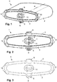
- a first embodiment of a hollow filter element 1 is shown, which is used for gas filtration, in particular for air filtration in internal combustion engines, preferably for trucks.
- the hollow filter element 1 has a filter medium body 2 which is designed as a hollow body and which encloses an internal flow space.
- the filter element has a strongly ovalized cross-sectional shape, with the long sides having a smaller curvature and the narrow sides having a greater curvature compared to an actual oval.
- the hollow filter element 1, the longitudinal axis of which is denoted by 4 between the axial end faces, is flowed through radially from the outside to the inside by the air to be cleaned, so that the inside flow space forms the clean side.
- the cleaned air is then introduced via an axial end face of the hollow filter element.
- the further axial end face of the hollow filter element 1 is closed by a continuous end disk 3, which extends both in the area of the end face of the filter medium body 2 and the enclosed, inner flow space.
- the plane of the end disk 3 is orthogonal to the longitudinal axis 4.
- the end disk 3 is made, for example, of polyurethane (PUR) and can be injection-molded or cast onto the hollow filter element 1.
- the hollow filter element 1 has a conical shape in the axial direction - based on the longitudinal axis 4. On the end disk 3, which is designed to be closed and closes the inner flow space, the hollow filter element 1 has a smaller cross-sectional area than on the opposite axial end face.
- a positioning element 5 is molded onto the end disk 3, which is located in the edge region of the end disk 3 on a longitudinal side and projects radially and axially beyond the outer contour of the hollow filter element.
- the positioning element 5 is designed in one piece with the end plate 3.
- the positioning recess 6 is located radially outside the outer contour of the hollow filter element 1 and serves to accommodate a housing-side sword for fixing in both radial or transverse directions 7 and 8 with respect to the longitudinal axis 4.
- a positive connection is established reached between the sword and the positioning element 5 in the two transverse directions 7 and 8. Any play with which the hollow filter element 1 is inserted into the filter housing can thereby be eliminated and the hollow filter element can be fixed in the filter housing.
- the sword on the housing side is inserted axially into the positioning recess 6 closed on the reverse.
- a first adjusting element 9 in the form of a cam is located on the longitudinal side opposite the positioning element 5 and, like the positioning element 5, is arranged in the middle of the longitudinal side.
- Two adjustment elements 10 are located on each narrow side.
- the adjusting elements 9 and 10 support the hollow filter element 1 in the installed position on the inner wall of the filter housing or the housing cover.
- Another adjustment element 11 is located in the center of the end face and, like the other adjustment elements, is formed in one piece with the end plate 3.
- the central adjusting element 11 has a recess into which a corresponding counter-adjusting element on the housing cover engages in the installed position.
- FIG. 3 Another embodiment of a hollow filter element 1 is shown, which basically has the same structure as the hollow filter element Figures 1 or 2 has. But there is a difference Fig. 3 the embodiment of the positioning element 5, which has a positioning recess 6 which is open at the edge, has a U-shaped cross section and is designed to be radially outwardly open. This enables the sword on the housing side to be guided into the recess 6 in the radial direction. As in the first exemplary embodiment, the fixation takes place in both transverse or radial directions.
- a housing cover 12 which can be placed on a filter housing for receiving the hollow filter housing.
- a sword 13 which extends axially towards the open side of the housing cover, but is arranged completely within the housing cover 12.
- the tip of the sword 13 is provided with a run-on bevel 14 which is flattened on the upper side and which facilitates the introduction into the positioning recess 6 on the positioning element 5.
- the hollow filter element 1 is inserted into the positioning recess 6, the hollow filter element 1 is lifted within the receiving filter housing, whereby the opposing cam-shaped adjusting element 9 is pressed against the inner wall of the housing.
- FIG. 6 the hollow filter element 1 is shown in the receiving filter housing 15.
- the housing cover 12 is placed on the filter housing 15.
- the tip of the sword 13 arranged in the housing cover 12 comes into engagement with the positioning recess 6 in the positioning element 5 and can extend as far as the underside of the hollow filter element 1.
- the run-up bevel 14 on the top of the tip of the sword 13 lifts the entire hollow filter element 1 upwards.
- the filter device 16 is shown in section.
- the filter device 16 comprises the filter housing 15 with the housing cover 12 attached and the hollow filter element 1 inserted into the filter housing 15. It can also be seen that the inside of the filter medium body 2 is lined with a support frame 17, which at the same time forms the delimiting wall of the internal flow space.
- the cleaned fluid is discharged from the inner flow space axially via the side opposite the housing cover 12, on which the hollow filter element 1 is provided with an end plate, which, however, only covers the filter medium body 2 and is open in the area of the inner flow space.
- the sword 13 protrudes into the positioning recess of the positioning element 5 and lifts the hollow filter element 1 so far that the overhead cam-shaped adjusting element 9 is pressed against the inner wall of the filter housing.
Landscapes
- Chemical & Material Sciences (AREA)
- Engineering & Computer Science (AREA)
- Chemical Kinetics & Catalysis (AREA)
- Physics & Mathematics (AREA)
- Geometry (AREA)
- Combustion & Propulsion (AREA)
- Mechanical Engineering (AREA)
- General Engineering & Computer Science (AREA)
- Filtering Of Dispersed Particles In Gases (AREA)
- Separation Using Semi-Permeable Membranes (AREA)
Description
- Die Erfindung bezieht sich auf ein Hohlfilterelement bzw. ringförmig geschlossenes Filterelementnach dem Oberbegriff des Anspruches 1.
- Aus der
WO 2014/202358 A1 ist ein Hohlfilterelement mit länglich-ovaler Querschnittsform bekannt, dessen Filtermediumkörper einen innenliegenden Strömungsraum umschließt. Das Hohlfilterelement ist in ein aufnehmendes Filtergehäuse eingesetzt und wird radial von außen nach innen von der zu reinigenden Luft durchströmt. An einer axialen Stirnseite des Hohlfilterelements befindet sich eine geschlossene Endscheibe, das gereinigte Fluid wird aus dem innenliegenden Strömungsraum über die gegenüberliegende Stirnseite axial abgeleitet. - Das Hohlfilterelement wird auf einer Längsseite liegend in das aufnehmende Filtergehäuse eingesetzt. Der Filtermediumkörper des Hohlfilterelements ist konisch zulaufend ausgebildet, so dass sich die Querschnittsfläche über die axiale Länge des Hohlfilterelements verjüngt. Am Gehäusedeckel, der auf das Filtergehäuse aufgesetzt wird, ist ein innenliegendes Schwert angeformt, das beim Aufsetzen des Gehäusedeckels ein noppenförmiges Positionierungselement an der Stirnseite des Hohlfilterelements untergreift und das Hohlfilterelement an dieser Stirnseite anhebt. Das Positionierungselement ragt radial über die Außenkontur des Filtermediumkörpers hinaus.
- Aus
WO 2004/039476 A1 ist ein Hohlfilterelement eines Luftfilters bekannt, das eine konische Form aufweist. An einer geschlossenen Endscheibe des Hohlfilterelements liegt eine Positionierungsvorrichtung in Form einer axialen Vertiefung vor. - Aus
DE 20 2004 020 174 U1 ist ein zylindrisches Hohlfilterelement eines Luftfilters bekannt, das an seiner geschlossenen Endscheibe ein unter einem spitzen Winkel zur Längsmittelachse abragendes Positionierungselement aufweist, das sich mit einer Radialkomponente über die geschlossene Endscheibe erstreckt. - Der Erfindung liegt die Aufgabe zugrunde, mit einfachen konstruktiven Maßnahmen ein Hohlfilterelement in der Weise auszubilden, dass eine sichere Montage und Aufnahme in einem Filtergehäuse gewährleistet ist.
- Diese Aufgabe wird erfindungsgemäß mit den Merkmalen des Anspruches 1 gelöst. Die Unteransprüche geben zweckmäßige Weiterbildungen an.
- Das erfindungsgemäße Hohlfilterelement wird vorzugsweise zur Gasfiltration eingesetzt, beispielsweise als Luftfilter zur Filtration der einer Brennkraftmaschine zuzuführenden Verbrennungsluft, beispielsweise in Lastkraftwagen. Das Hohlfilterelement umfasst einen Filtermediumkörper, der als Hohlkörper ausgebildet ist und an dem die Filtration des zu reinigenden Fluids stattfindet. An zumindest einer axialen Stirnseite ist der Filtermediumkörper von einer Endscheibe abgedeckt, die vorzugsweise den innenliegenden Strömungsraum im Filtermediumkörper strömungsdicht verschließt. Auch an der gegenüberliegenden axialen Stirnseite kann eine Endscheibe angeordnet sein, die sich zumindest über den Bereich des Filtermediumkörpers erstreckt, wobei ggf. eine Strömungsöffnung der Endscheibe frei liegt, so dass Fluid zwischen dem innenliegenden Strömungsraum und der Umgebung ausgetauscht werden kann. Die Durchströmung des Filtermediumkörpers erfolgt vorzugsweise in Radialrichtung, insbesondere radial von außen nach innen, so dass der innenliegende Strömungsraum die Reinseite bildet, aus der das gereinigte Fluid axial abgeleitet wird. Der Filtermediumkörper kann prinzipiell eine beliebige Querschnittsform aufweisen, beispielsweise kreisförmig, oval oder stadionförmig.
- An einer Endscheibe befindet sich ein Positionierungselement, das beim Schließen des Gehäusedeckels und im eingebauten Zustand des Filterelements mit einem gehäuseseitigen Schwert zusammenwirkt, das das Filterelement an dem Positionierungselement abstützt. Mit dem Einsetzen des Filterelements in das Filtergehäuse oder mit dem Aufsetzen und Schließen des Gehäusedeckels gelangt das gehäuseseitige Schwert in Kontakt mit dem Positionierungselement, hebt ggf. das Filterelement an zum Erreichen seiner endgültigen Einbaulage und stützt das Filterelement ab. In das Positionierungselement ist erfindungsgemäß eine Positionierausnehmung eingebracht.
- Um einen lagerichtigen Sitz des Filterelements im Filtergehäuse zu gewährleisten, ist das Positionierungselement an der Endscheibe des Hohlfilterelements in der Weise ausgebildet, dass eine formschlüssige Aufnahme des Schwerts im oder am Positionierungselement in zwei verschiedene Quer- bzw. Radialrichtungen - bezogen auf die Längsachse des Filterelements - gewährleistet ist. Demzufolge besteht zwischen dem gehäuseseitigen Schwert und dem Positionierungselement an dem Hohlfilterelement eine formschlüssige Verbindung in beide Querrichtungen, die die Ebene der Endscheibe aufspannen und beide radial zur Längsachse des Hohlfilterelements verlaufen. Nimmt das Hohlfilterelement in Einbaulage beispielsweise eine liegende Position ein, in der die Längsachse des Hohlfilterelements orthogonal zum Gewichtskraftvektor verläuft, so kann über die Verbindung zwischen dem filterelementseitigen Positionierungselement und dem gehäuseseitigen Schwert eine lagerichtige Halterung des Hohlfilterelements in Vertikalrichtung sowie in Querrichtung erreicht werden.
- Das Positionierungselement ist vorteilhafterweise einteilig mit der Endscheibe ausgebildet. Diese besteht beispielsweise aus Polyurethan, so dass auch das Positionierungselement aus diesem Material gefertigt ist. Es kommen aber auch andere Materialien für die Endscheibe und das Positionierungselement in Betracht, beispielsweise Kunststoff oder Metall. Des Weiteren ist es möglich, dass die Endscheibe und das Positionierungselement aus unterschiedlichen Materialien gefertigt sind, jedoch das Positionierungselement fest an der Endscheibe angeordnet ist.
- Das Positionierungselement ragt radial über die Endscheibe hinaus. Das Positionierungselement kann zusätzlich oder alternativ auch in Axialrichtung über den Randbereich der Endscheibe hinausragen. Bei axial und/oder radial hinausragender Anordnung des Positionierungselements an der Endscheibe kann das Positionierungselement in vereinfachter Weise von dem gehäuseseitigen Schwert erfasst und das Hohlfilterelement in gewünschter Weise fixiert werden.
- In die Positionierausnehmung ragt in montierter Lage das gehäuseseitige Schwert ein. Hierdurch ist die formschlüssige Aufnahme des Schwerts im Positionierungselement in zwei verschiedene Querrichtungen sicher gewährleistet. Die Positionierausnehmung ist entweder umseitig geschlossen ausgebildet oder randseitig offen und z.B. U-förmig ausgeführt. Die randseitig offene Ausführung hat den Vorteil, dass das Schwert in Radialrichtung in die Positionierausnehmung eingeführt werden kann. Bei der umseitig geschlossenen Positionierausnehmung wird das Schwert in Achsrichtung in die Positionierausnehmung eingeführt.
- Gemäß noch einer weiteren zweckmäßigen Ausführung weist das Hohlfilterelement eine ovale oder annähernd ovale Querschnittsform auf. Es kann z.B. zweckmäßig sein, die Querschnittsform des Hohlfilterelements als langgestrecktes Oval auszubilden, das verhältnismäßig lang ausgeführte Längsseiten und kurz ausgeführte Schmalseiten besitzt. Bei ovaler oder annähernd ovaler Querschnittsform sitzt das Positionierungselement vorteilhafterweise an einer Längsseite. So ist es insbesondere zweckmäßig, bei liegender Einbausituation des Hohlfilterelements im aufnehmenden Filtergehäuse das Positionierungselement an der untenliegenden Längsseite, insbesondere mittig, am Hohlfilterelement anzuordnen. Eine Anordnung an einer Schmalseite ist insbesondere bei einer stehenden Einbausituation vorteilhaft.
- Soweit das Positionierungselement mit einer Positionierausnehmung versehen ist, ragt diese vorzugsweise über den Randbereich des Hohlfilterelements hinaus, so dass das gehäuseseitige Schwert in die Positionierausnehmung ungehindert einfahren kann.
- Das Hohlfilterelement ist in Achsrichtung konusförmig ausgebildet. Dementsprechend weist das Hohlfilterelement an seinen beiden axial gegenüberliegenden Stirnseiten eine unterschiedlich große Querschnittsfläche auf. Das Hohlfilterelement verjüngt sich zu der axialen Stirnseite hin, an der das Positionierungselement angeordnet ist. Der Konuswinkel liegt beispielsweise in einem Winkelbereich bis maximal 10° oder bis maximal 5°. In einer alternativen Ausführung ist das Hohlfilterelement zylindrisch ausgebildet.
- Es kann des Weiteren zweckmäßig sein, an der Endscheibe, an der sich das Positionierungselement befindet, ein oder mehrere zusätzliche Justierelemente anzuordnen. So ist es beispielsweise vorteilhaft, mittig an der geschlossenen Endscheibe mit umseitigem Abstand zum Randbereich ein zentrales Justierelement anzuordnen, mit dem in Einbaulage ein gehäuseseitiges Gegenjustierelement zusammenwirkt. Zusätzlich oder alternativ können am Randbereich der Endscheibe überstehende Justierelemente in Form eines oder mehrerer Nocken angeordnet sein, die sich in Einbaulage an der Gehäuseinnenwand des aufnehmenden Filtergehäuses abstützen.
- Das Schwert, welches mit dem Positionierungselement formschlüssig zusammenwirkt, befindet sich vorteilhafterweise am Gehäusedeckel, der auf ein topfförmiges Bauteil des Filtergehäuses aufsetzbar ist. Das Schwert kann ggf. mit einer Anlaufschräge versehen sein, die das Einfädeln in die Positionierausnehmung des Positionierungselements und das Anheben des Hohlfilterelements erleichtert.
- Weitere Vorteile und zweckmäßige Ausführungen sind den weiteren Ansprüchen, der Figurenbeschreibung und den Zeichnungen zu entnehmen. Es zeigen:
- Fig. 1
- eine perspektivische Ansicht eines oval ausgebildeten Hohlfilterelements, mit einem Positionierungselement im Randbereich einer stirnseitigen Endscheibe, wobei das Positionierungselement mit einer umseitig geschlossenen Positionierausnehmung versehen ist,
- Fig. 2
- eine Draufsicht auf die axiale Stirnseite des Hohlfilterelements,
- Fig. 3
- ein Hohlfilterelement in einer weiteren Ausführung, bei der das randseitige Positionierungselement eine offene Positionierausnehmung aufweist,
- Fig. 4
- in perspektivischer Ansicht ein Gehäusedeckel mit an der Deckelinnenseite angeordnetem Schwert, das in Einbaulage in die Positionierausnehmung des Positionierungselements einragt,
- Fig. 5
- das Schwert in vergrößerter Darstellung,
- Fig. 6
- eine Filtereinrichtung mit einem Filtergehäuse und dem eingesetzten Hohlfilterelement aus
Fig. 1 bzw. 2, - Fig. 7
- eine vergrößerte Ansicht der Stirnseite des Hohlfilterelements mit angenähertem Gehäusedeckel,
- Fig. 8
- einen Schnitt längs durch die Filtereinrichtung mit aufgesetztem Gehäusedeckel, wobei das Schwert an der Deckelinnenseite in die Positionierausnehmung des Positionierungselements hineinragt.
- In den Figuren sind gleiche Bauteile mit gleichen Bezugszeichen versehen.
- In
Figuren 1 und 2 ist ein erstes Ausführungsbeispiel eines Hohlfilterelements 1 dargestellt, das zur Gasfiltration, insbesondere zur Luftfiltration in Brennkraftmaschinen, vorzugsweise für Lastkraftwagen, eingesetzt wird. Das Hohlfilterelement 1 weist einen als Hohlkörper ausgebildeten Filtermediumkörper 2 auf, der einen innenliegenden Strömungsraum umschließt. Das Filterelement weist eine stark ovalisierte Querschnittsform auf, wobei die Längsseiten im Vergleich zu einem tatsächlichen Oval eine geringere Krümmung und die Schmalseiten eine stärkere Krümmung aufweisen. Das Hohlfilterelement 1, dessen Längsachse zwischen den axialen Stirnseiten mit 4 bezeichnet ist, wird radial von außen nach innen von der zu reinigenden Luft durchströmt, so dass der innenliegende Strömungsraum die Reinseite bildet. Die gereinigte Luft wird anschließend über eine axiale Stirnseite des Hohlfilterelements eingeleitet. - Die weitere axiale Stirnseite des Hohlfilterelements 1 ist von einer durchgehenden Endscheibe 3 verschlossen, die sich sowohl im Bereich der Stirnseite des Filtermediumkörpers 2 als auch des umschlossenen, innenliegenden Strömungsraums erstreckt. Die Ebene der Endscheibe 3 liegt orthogonal zur Längsachse 4. Die Endscheibe 3 ist beispielsweise aus Polyurethan (PUR) gefertigt und kann an das Hohlfilterelement 1 angespritzt bzw. angegossen sein.
- Das Hohlfilterelement 1 weist in Achsrichtung - bezogen auf die Längsachse 4 - Konusform auf. An der Endscheibe 3, die geschlossen ausgebildet ist und den innenliegenden Strömungsraum verschließt, besitzt das Hohlfilterelement 1 eine kleinere Querschnittsfläche als an der gegenüberliegenden axialen Stirnseite.
- An der Endscheibe 3 ist ein Positionierungselement 5 angeformt, das sich im Randbereich der Endscheibe 3 an einer Längsseite befindet und radial und axial über die Außenkontur des Hohlfilterelements hinausragt. Das Positionierungselement 5 ist einstückig mit der Endscheibe 3 ausgebildet. In das Positionierungselement 5 ist eine Positionierausnehmung 6 eingebracht, die umseitig geschlossen ist. Die Positionierausnehmung 6 befindet sich radial außerhalb der Außenkontur des Hohlfilterelements 1 und dient zur Aufnahme eines gehäuseseitigen Schwerts zur Fixierung in beide Radial- bzw. Querrichtungen 7 und 8 gegenüber der Längsachse 4. Mit dem Eingreifen des gehäuseseitigen Schwerts in die Positionierausnehmung 6 wird eine formschlüssige Verbindung zwischen Schwert und Positionierungselement 5 in die beiden Querrichtungen 7 und 8 erreicht. Ein eventuell vorhandenes Spiel, mit dem das Hohlfilterelement 1 in das Filtergehäuse eingesetzt ist, kann hierdurch eliminiert und das Hohlfilterelement im Filtergehäuse fixiert werden. Das gehäuseseitige Schwert wird axial in die umseitig geschossene Positionierausnehmung 6 eingeführt.
- Im Bereich des Außenumfangs sind an der Endscheibe drei weitere Positionier- bzw. Justierelemente 9, 10 angeformt, die axial und radial über die Kontur des Hohlfilterelements 1 hinausragen. Ein erstes Justierelement 9 in Form eines Nockens befindet sich an der dem Positionierungselement 5 gegenüberliegenden Längsseite und ist ebenso wie das Positionierungselement 5 in der Mitte der Längsseite angeordnet. Jeweils zwei Justierelemente 10 befinden sich an jeder Schmalseite. Die Justierelemente 9 und 10 stützen das Hohlfilterelement 1 in Einbaulage an der Innenwand des aufnehmen Filtergehäuses bzw. des Gehäusedeckels ab.
- Ein weiteres Justierelement 11 befindet sich mittig an der Stirnseite und ist ebenso wie die weiteren Justierelemente einteilig mit der Endscheibe 3 ausgebildet. Das zentrische Justierelement 11 weist eine Vertiefung auf, in die ein entsprechendes Gegenjustierelement am Gehäusedeckel in Einbaulage eingreift.
- In
Fig. 3 ist ein weiteres Ausführungsbeispiel eines Hohlfilterelements 1 dargestellt, das grundsätzlich den gleichen Aufbau wie das Hohlfilterelement ausFiguren 1 bzw. 2 aufweist. Unterschiedlich ist aber beiFig. 3 die Ausführung des Positionierungselements 5, das eine randseitig offene Positionierausnehmung 6 aufweist, die einen U-förmigen Querschnitt besitzt und radial nach außen offen ausgebildet ist. Dies ermöglicht es, dass das gehäuseseitige Schwert in Radialrichtung in die Ausnehmung 6 hineingeführt wird. Die Fixierung erfolgt wie beim ersten Ausführungsbeispiel in beide Quer- bzw. Radialrichtungen. - In
Figuren 4 und 5 ist ein Gehäusedeckel 12 dargestellt, der auf ein Filtergehäuse zur Aufnahme des Hohlfiltergehäuses aufgesetzt werden kann. An der Innenwand des Gehäusedeckels 12 befindet sich ein Schwert 13, das sich axial zur offenen Seite des Gehäusedeckels hin erstreckt, jedoch vollständig innerhalb des Gehäusedeckels 12 angeordnet ist. Der vergrößerten Darstellung gemäßFig. 5 ist zu entnehmen, dass die Spitze des Schwertes 13 mit einer an der Oberseite abgeflachten Anlaufschräge 14 versehen ist, welche das Einführen in die Positionierausnehmung 6 am Positionierungselement 5 erleichtert. Außerdem wird mit dem Einführen in die Positionierausnehmung 6 zugleich ein Anheben des Hohlfilterelements 1 innerhalb des aufnehmenden Filtergehäuses erreicht, wodurch das gegenüberliegende nockenförmige Justierelement 9 gegen die Gehäuseinnenwand gedrückt wird. - In
Fig. 6 ist das Hohlfilterelement 1 im aufnehmenden Filtergehäuse 15 dargestellt. Auf das Filtergehäuse 15 wird der Gehäusedeckel 12 aufgesetzt. Mit dem Annähern des Gehäusedeckels 12 an das Hohlfilterelement 1 (Fig. 7 ) gelangt die Spitze des im Gehäusedeckel 12 angeordneten Schwerts 13 in Eingriff mit der Positionierausnehmung 6 im Positionierungselement 5 und kann sich bis zur Unterseite des Hohlfilterelements 1 erstrecken. Die Anlaufschräge 14 an der Oberseite der Spitze des Schwerts 13 hebt hierbei das gesamte Hohlfilterelement 1 nach oben an. - In
Fig. 8 ist die Filtereinrichtung 16 im Schnitt dargestellt. Die Filtereinrichtung 16 umfasst das Filtergehäuse 15 mit aufgesetztem Gehäusedeckel 12 und das in das Filtergehäuse 15 eingesetzte Hohlfilterelement 1. Zu erkennen ist außerdem, dass der Filtermediumkörper 2 an seiner Innenseite von einem Stützgerüst 17 ausgekleidet ist, das zugleich die begrenzende Wand des innenliegenden Strömungsraums bildet. Die Ableitung des gereinigten Fluids aus dem innenliegenden Strömungsraum erfolgt axial über die dem Gehäusedeckel 12 gegenüberliegende Seite, an der das Hohlfilterelement 1 mit einer Endscheibe versehen ist, die jedoch nur den Filtermediumkörper 2 abdeckt und im Bereich des innenliegenden Strömungsraums offen ausgebildet ist. - Das Schwert 13 ragt in die Positionierausnehmung des Positionierungselements 5 ein und hebt das Hohlfilterelement 1 so weit an, dass das obenliegende nockenförmige Justierelement 9 gegen die Innenwand des Filtergehäuses gepresst wird.
Claims (10)
- Hohlfilterelement eines Luftfilters, zum Einsetzen in ein öffenbares Filtergehäuse, mit einem als Hohlkörper ausgebildeten Filtermediumkörper (2), der einen innenliegenden Strömungsraum umschließt, mit mindestens einer geschlossenen Endscheibe (3), die den Filtermediumkörper (2) an einer axialen Stirnseite abdeckt, wobei an der Endscheibe (3) ein mit einem gehäuseseitigen Schwert (13) zusammenwirkendes Positionierungselement (5) angeordnet ist, wobei das Positionierungselement (5) zur formschlüssigen Aufnahme des Schwerts (13) in zwei verschiedene Querrichtungen (7, 8) ausgebildet ist und in das Positionierungselement (5) eine Positionierausnehmung (6) eingebracht ist, dadurch gekennzeichnet, dass das Positionierungselement (5) radial über die geschlossene Endscheibe (3) hinausragt und das Hohlfilterelement (1) in Achsrichtung konusförmig ausgebildet ist, wobei sich das Hohlfilterelement zu der axialen Stirnseite hin, an der das Positionierungselement vorliegt, verjüngt.
- Hohlfilterelement nach Anspruch 1, dadurch gekennzeichnet, dass das Positionierungselement (5) axial über den Randbereich der Endscheibe (3) hinausragt.
- Hohlfilterelement nach Anspruch 1 oder 2, dadurch gekennzeichnet, dass die Positionierausnehmung (6) eine umseitig geschlossene Positionierausnehmung (6) ist.
- Hohlfilterelement nach einem der Ansprüche 1 bis 3, dadurch gekennzeichnet, dass die Positionierausnehmung (6) eine randseitig offene Positionierausnehmung (6) ist.
- Hohlfilterelement nach einem der Ansprüche 1 bis 4, dadurch gekennzeichnet, dass das Positionierungselement (5) einteilig mit der Endscheibe (3) ausgebildet ist.
- Hohlfilterelement nach einem der Ansprüche 1 bis 5, dadurch gekennzeichnet, dass die Querschnittsform des Hohlfilterelements (1) zumindest näherungsweise als ein Oval ausgebildet ist.
- Hohlfilterelement nach Anspruch 6, dadurch gekennzeichnet, dass das Positionierungselement (5) an der Längsseite des Ovals angeordnet ist.
- Filtereinrichtung mit einem Hohlfilterelement nach einem der Ansprüche 1 bis 7 und mit einem Filtergehäuse (15) zur Aufnahme des Hohlfilterelements (1), wobei an einem Gehäusebauteil ein Schwert (13) angeordnet ist, das in das Positionierungselement (5) an der Endscheibe (3) formschlüssig einragt.
- Filtereinrichtung nach Anspruch 8, dadurch gekennzeichnet, dass das Schwert (13) eine Anlaufschräge (14) zum Einfädeln in das Positionierungselement (5) und Anheben des Hohlfilterelements (1) aufweist.
- Filtereinrichtung nach Anspruch 8 oder 9, dadurch gekennzeichnet, dass das Schwert (13) am Gehäusedeckel (12) angeordnet ist.
Applications Claiming Priority (2)
| Application Number | Priority Date | Filing Date | Title |
|---|---|---|---|
| DE102016005353.4A DE102016005353A1 (de) | 2016-05-03 | 2016-05-03 | Hohlfilterelement, insbesondere zur Gasfiltration |
| PCT/EP2017/055294 WO2017190873A1 (de) | 2016-05-03 | 2017-03-07 | Hohlfilterelement, insbesondere zur gasfiltration |
Publications (2)
| Publication Number | Publication Date |
|---|---|
| EP3452202A1 EP3452202A1 (de) | 2019-03-13 |
| EP3452202B1 true EP3452202B1 (de) | 2020-12-09 |
Family
ID=58231637
Family Applications (1)
| Application Number | Title | Priority Date | Filing Date |
|---|---|---|---|
| EP17709080.0A Active EP3452202B1 (de) | 2016-05-03 | 2017-03-07 | Hohlfilterelement, insbesondere zur gasfiltration |
Country Status (7)
| Country | Link |
|---|---|
| US (1) | US11338237B2 (de) |
| EP (1) | EP3452202B1 (de) |
| CN (1) | CN109069973B (de) |
| BR (1) | BR112018071725B1 (de) |
| DE (2) | DE102016005353A1 (de) |
| RU (1) | RU2734392C2 (de) |
| WO (1) | WO2017190873A1 (de) |
Families Citing this family (7)
| Publication number | Priority date | Publication date | Assignee | Title |
|---|---|---|---|---|
| DE112018006269T5 (de) * | 2017-12-08 | 2020-08-20 | Cummins Filtration Ip, Inc. | Ovale Dichtung mit Stabilisierungskontur |
| FR3078490B1 (fr) | 2018-03-05 | 2022-10-14 | Cummins Filtration Sarl | Element filtrant et boitier ayant des sections transversales non circulaires |
| US10918978B2 (en) | 2018-05-08 | 2021-02-16 | Cummins Filtration Ip, Inc. | Oval filter with exterior elliptical radial seal and internal support structure |
| USD884866S1 (en) | 2018-05-08 | 2020-05-19 | Cummins Filtration Ip, Inc. | Filter element |
| USD969289S1 (en) | 2020-03-05 | 2022-11-08 | Cummins Filtration Inc. | Filter element |
| DE102020116398B4 (de) | 2020-06-22 | 2025-09-04 | Mann+Hummel Gmbh | Filterelement, Gehäuse für ein Filtersystem und Filtersystem mit einem Filterelement und einem Gehäuse |
| DE102020128911A1 (de) | 2020-11-03 | 2022-05-05 | Mann+Hummel Gmbh | Filtersystem und Filterelement |
Family Cites Families (31)
| Publication number | Priority date | Publication date | Assignee | Title |
|---|---|---|---|---|
| US4211543A (en) * | 1978-04-24 | 1980-07-08 | Donaldson Company, Inc. | Air cleaner with replaceable filter element |
| US4204846A (en) * | 1978-05-26 | 1980-05-27 | Donaldson Company, Inc. | Self-cleaning air filter |
| CN2177813Y (zh) * | 1993-08-16 | 1994-09-21 | 牛纯成 | 一种空气滤清器 |
| US5547480A (en) * | 1994-01-21 | 1996-08-20 | Donaldson Company, Inc. | Cylindrical air filter with radially directed seal |
| CN2232493Y (zh) * | 1995-10-05 | 1996-08-07 | 谢礼澄 | 内燃机电子空气滤清器 |
| US20040035094A1 (en) * | 2002-04-10 | 2004-02-26 | Jersey Ray De | Diesel engine exhaust filter |
| JP4443513B2 (ja) * | 2002-10-28 | 2010-03-31 | ドナルドソン カンパニー,インコーポレイティド | エアクリーナ、交換可能なフィルタ・カートリッジと方法 |
| DE102004008264A1 (de) * | 2004-02-20 | 2005-09-01 | Mann + Hummel Gmbh | Verfahren zur Herstellung einer dichten Verbindung zwischen einem mehrschichtigen Kunststoffmaterial und einem Filtermedium |
| CN2727431Y (zh) * | 2004-05-25 | 2005-09-21 | 郭玲玲 | 进气管改良结构 |
| DE202004020174U1 (de) * | 2004-12-23 | 2005-03-17 | Mann & Hummel Gmbh | Luftfilter |
| EP1754525B1 (de) * | 2005-08-16 | 2011-01-19 | Donaldson Company, Inc. | Luftreiniger mit verdrehsicherer Anordnung und Verfahren |
| DE202005014125U1 (de) * | 2005-09-08 | 2007-01-25 | Mann + Hummel Gmbh | Abscheider zur Reinigung eines Fluidstromes |
| BRPI0617353A2 (pt) | 2005-10-11 | 2011-07-26 | Donaldson Co Inc | arranjo, montagem e mÉtodos de filtro de ar |
| US8206482B2 (en) * | 2008-07-04 | 2012-06-26 | Emerson Electric Co. | Vacuum appliance filter assemblies and associated vacuum systems |
| US9510718B2 (en) * | 2008-07-04 | 2016-12-06 | Emerson Electric Co. | Wet/dry vacuum cleaner filter for wet material collection |
| DE102010014277B4 (de) | 2009-10-12 | 2020-03-12 | Mann+Hummel Gmbh | Filtervorrichtung und Hauptfilterelement für eine Filtervorrichtung |
| DE102009050259A1 (de) | 2009-10-21 | 2011-05-12 | Mann + Hummel Gmbh | Filtersystem und Filterelement zur Filtrierung von Fluiden |
| CN201751560U (zh) * | 2010-07-07 | 2011-02-23 | 浙江吉利汽车研究院有限公司 | 一种进气管结构 |
| CN104540573B (zh) * | 2012-08-22 | 2017-10-24 | 曼·胡默尔有限公司 | 尤其用于气体过滤的过滤装置 |
| EP2888023B1 (de) * | 2012-08-22 | 2019-03-20 | MANN+HUMMEL GmbH | Filtereinrichtung, insbesondere zur gasfiltration |
| US9067161B2 (en) * | 2012-11-29 | 2015-06-30 | Donaldson Company, Inc. | Filter cartridges; features and methods of assembly; air cleaner assemblies; and, filter cartridge combinations |
| US9726123B2 (en) * | 2013-06-20 | 2017-08-08 | Mann+Hummel Gmbh | Air filter, filter element and filter housing of an air filter |
| DE102014006850B4 (de) * | 2013-06-20 | 2022-08-25 | Mann+Hummel Gmbh | Filtergehäuse, Hohlfilterelement und Filter |
| DE102013014489B4 (de) * | 2013-09-02 | 2020-04-23 | Mann+Hummel Gmbh | Filterelement, Filtersystem mit einem Filterelement und Verwendung |
| DE102013015143B4 (de) * | 2013-09-13 | 2016-05-25 | Mann + Hummel Gmbh | Filter für Fluid, Filterelement und Filtergehäuse eines Filters |
| DE102013017034A1 (de) | 2013-10-15 | 2015-04-16 | Mann + Hummel Gmbh | Filtereinrichtung, insbesondere Gasfilter |
| DE102014009323B4 (de) * | 2014-06-27 | 2016-11-24 | Mann + Hummel Gmbh | Filterelement eines Filters, Heizkäfig für ein Filterelement und Verfahren zur Herstellung eines Filterelements |
| WO2016082853A1 (en) * | 2014-11-24 | 2016-06-02 | Mann+Hummel Gmbh | Filtering device, filtering element and maintenance process of a filtering device |
| DE102015004645A1 (de) * | 2015-04-15 | 2016-10-20 | Mann + Hummel Gmbh | Filterelement, insbesondere zur Gasfiltration |
| CN105351118A (zh) * | 2015-12-15 | 2016-02-24 | 张家港市江南汽车制造有限公司 | 汽车用空气滤清器 |
| CN105498378A (zh) * | 2015-12-31 | 2016-04-20 | 东莞市利发爱尔空气净化系统有限公司 | 一种双过滤桶结构 |
-
2016
- 2016-05-03 DE DE102016005353.4A patent/DE102016005353A1/de not_active Withdrawn
-
2017
- 2017-03-07 RU RU2018138387A patent/RU2734392C2/ru active
- 2017-03-07 DE DE112017002315.7T patent/DE112017002315A5/de not_active Withdrawn
- 2017-03-07 WO PCT/EP2017/055294 patent/WO2017190873A1/de not_active Ceased
- 2017-03-07 CN CN201780027565.0A patent/CN109069973B/zh active Active
- 2017-03-07 BR BR112018071725-8A patent/BR112018071725B1/pt active IP Right Grant
- 2017-03-07 EP EP17709080.0A patent/EP3452202B1/de active Active
-
2018
- 2018-11-01 US US16/178,195 patent/US11338237B2/en active Active
Non-Patent Citations (1)
| Title |
|---|
| None * |
Also Published As
| Publication number | Publication date |
|---|---|
| DE102016005353A1 (de) | 2017-11-09 |
| CN109069973A (zh) | 2018-12-21 |
| BR112018071725B1 (pt) | 2022-11-29 |
| RU2018138387A (ru) | 2020-06-03 |
| RU2018138387A3 (de) | 2020-06-03 |
| US20190060816A1 (en) | 2019-02-28 |
| WO2017190873A1 (de) | 2017-11-09 |
| BR112018071725A2 (pt) | 2019-02-19 |
| EP3452202A1 (de) | 2019-03-13 |
| DE112017002315A5 (de) | 2019-02-28 |
| RU2734392C2 (ru) | 2020-10-15 |
| CN109069973B (zh) | 2021-11-09 |
| US11338237B2 (en) | 2022-05-24 |
Similar Documents
| Publication | Publication Date | Title |
|---|---|---|
| WO2017190873A1 (de) | Hohlfilterelement, insbesondere zur gasfiltration | |
| DE102014016908B4 (de) | Filterelement mit Filterbalg, Filtersystem und Verwendung des Filtersystems | |
| EP2490786B1 (de) | Filtereinrichtung | |
| DE102009000231B4 (de) | Ventilbetätigungseinrichtung eines Ventils, Flüssigkeitsbehälter einer Flüssigkeitsbehandlungsvorrichtung, Flüssigkeitsbehandlungsvorrichtung sowie Verwendung einer solchen Vorrichtung | |
| EP3525910B1 (de) | Filtereinrichtung und rundfilterelement, insbesondere zur gasfiltration | |
| WO2009109484A1 (de) | Schellenfixierung für ein schlauchende | |
| EP3981494A1 (de) | Rundfilterelement, insbesondere zur gasfiltration | |
| DE202005016046U1 (de) | Sanitäres Einbauteil | |
| EP3057679A1 (de) | Filterelement, insbesondere zur gasfiltration | |
| EP2125157B1 (de) | Fluidfilter mit einem in ein filtergehäuse einsetzbaren filterelement | |
| EP3475580B1 (de) | Gebläseradscheibe und gebläserad | |
| EP1800729B1 (de) | Luftfilter und Filtereinsatz | |
| EP4171781B1 (de) | Filtereinrichtung mit einem filterelement | |
| WO2016071201A1 (de) | Filterelement, insbesondere zur gasfiltration | |
| EP3452201B1 (de) | Filtereinrichtung, insbesondere gasfilter | |
| EP3252312A1 (de) | Rückschlag-/auslassventil für eine vakuumpumpe | |
| DE102012006426A1 (de) | Filtereinrichtung, insbesondere Luftfilter | |
| DE102006015757A1 (de) | Becherhalter für ein Kraftfahrzeug | |
| DE112019002182B4 (de) | Rundfilterelement, insbesondere zur gasfiltration und filtereinrichtung | |
| EP2218831B1 (de) | Strassenschachtabdeckung mit einer schachteinstiegshilfehalterung | |
| WO2017190871A1 (de) | Ringförmiges filterelement, insbesondere zur gasfiltration, und filtereinrichtung | |
| DE19823339A1 (de) | Vorrichtung zum lösbaren Verbinden eines hohlzylinderartigen Filterelementes mit einer Filtervorrichtung | |
| WO2014029811A1 (de) | Filtereinrichtung, insbesondere zur gasfiltration | |
| EP1747941A2 (de) | Sensorhalterung zur Herstellung eines Sensors an einem Fahrzeugteil | |
| DE1632632A1 (de) | Filterkartusche fuer Gasfeuerzeuge und Verfahren zu deren Herstellung |
Legal Events
| Date | Code | Title | Description |
|---|---|---|---|
| STAA | Information on the status of an ep patent application or granted ep patent |
Free format text: STATUS: UNKNOWN |
|
| STAA | Information on the status of an ep patent application or granted ep patent |
Free format text: STATUS: THE INTERNATIONAL PUBLICATION HAS BEEN MADE |
|
| PUAI | Public reference made under article 153(3) epc to a published international application that has entered the european phase |
Free format text: ORIGINAL CODE: 0009012 |
|
| STAA | Information on the status of an ep patent application or granted ep patent |
Free format text: STATUS: REQUEST FOR EXAMINATION WAS MADE |
|
| 17P | Request for examination filed |
Effective date: 20181002 |
|
| AK | Designated contracting states |
Kind code of ref document: A1 Designated state(s): AL AT BE BG CH CY CZ DE DK EE ES FI FR GB GR HR HU IE IS IT LI LT LU LV MC MK MT NL NO PL PT RO RS SE SI SK SM TR |
|
| AX | Request for extension of the european patent |
Extension state: BA ME |
|
| DAV | Request for validation of the european patent (deleted) | ||
| DAX | Request for extension of the european patent (deleted) | ||
| STAA | Information on the status of an ep patent application or granted ep patent |
Free format text: STATUS: EXAMINATION IS IN PROGRESS |
|
| 17Q | First examination report despatched |
Effective date: 20200327 |
|
| GRAP | Despatch of communication of intention to grant a patent |
Free format text: ORIGINAL CODE: EPIDOSNIGR1 |
|
| STAA | Information on the status of an ep patent application or granted ep patent |
Free format text: STATUS: GRANT OF PATENT IS INTENDED |
|
| INTG | Intention to grant announced |
Effective date: 20200820 |
|
| GRAS | Grant fee paid |
Free format text: ORIGINAL CODE: EPIDOSNIGR3 |
|
| GRAA | (expected) grant |
Free format text: ORIGINAL CODE: 0009210 |
|
| STAA | Information on the status of an ep patent application or granted ep patent |
Free format text: STATUS: THE PATENT HAS BEEN GRANTED |
|
| AK | Designated contracting states |
Kind code of ref document: B1 Designated state(s): AL AT BE BG CH CY CZ DE DK EE ES FI FR GB GR HR HU IE IS IT LI LT LU LV MC MK MT NL NO PL PT RO RS SE SI SK SM TR |
|
| REG | Reference to a national code |
Ref country code: GB Ref legal event code: FG4D Free format text: NOT ENGLISH |
|
| RIN1 | Information on inventor provided before grant (corrected) |
Inventor name: DONAUER, NADINE Inventor name: GRUBER, MARTIN Inventor name: WITTMERS,CHRISTOPH Inventor name: PEREIRA MADEIRA, PEDRO MIGUEL Inventor name: HOLZWARTH, MARCEL Inventor name: WINTER, MANFRED Inventor name: KRIEGER, JOACHIM-PAUL Inventor name: FRANZ, ANDREAS Inventor name: FRITZSCHING, TORSTEN |
|
| REG | Reference to a national code |
Ref country code: AT Ref legal event code: REF Ref document number: 1342829 Country of ref document: AT Kind code of ref document: T Effective date: 20201215 Ref country code: CH Ref legal event code: EP |
|
| REG | Reference to a national code |
Ref country code: DE Ref legal event code: R096 Ref document number: 502017008572 Country of ref document: DE |
|
| REG | Reference to a national code |
Ref country code: IE Ref legal event code: FG4D Free format text: LANGUAGE OF EP DOCUMENT: GERMAN |
|
| PG25 | Lapsed in a contracting state [announced via postgrant information from national office to epo] |
Ref country code: RS Free format text: LAPSE BECAUSE OF FAILURE TO SUBMIT A TRANSLATION OF THE DESCRIPTION OR TO PAY THE FEE WITHIN THE PRESCRIBED TIME-LIMIT Effective date: 20201209 Ref country code: NO Free format text: LAPSE BECAUSE OF FAILURE TO SUBMIT A TRANSLATION OF THE DESCRIPTION OR TO PAY THE FEE WITHIN THE PRESCRIBED TIME-LIMIT Effective date: 20210309 Ref country code: FI Free format text: LAPSE BECAUSE OF FAILURE TO SUBMIT A TRANSLATION OF THE DESCRIPTION OR TO PAY THE FEE WITHIN THE PRESCRIBED TIME-LIMIT Effective date: 20201209 Ref country code: GR Free format text: LAPSE BECAUSE OF FAILURE TO SUBMIT A TRANSLATION OF THE DESCRIPTION OR TO PAY THE FEE WITHIN THE PRESCRIBED TIME-LIMIT Effective date: 20210310 |
|
| RAP4 | Party data changed (patent owner data changed or rights of a patent transferred) |
Owner name: MANN+HUMMEL GMBH |
|
| PG25 | Lapsed in a contracting state [announced via postgrant information from national office to epo] |
Ref country code: SE Free format text: LAPSE BECAUSE OF FAILURE TO SUBMIT A TRANSLATION OF THE DESCRIPTION OR TO PAY THE FEE WITHIN THE PRESCRIBED TIME-LIMIT Effective date: 20201209 Ref country code: BG Free format text: LAPSE BECAUSE OF FAILURE TO SUBMIT A TRANSLATION OF THE DESCRIPTION OR TO PAY THE FEE WITHIN THE PRESCRIBED TIME-LIMIT Effective date: 20210309 Ref country code: LV Free format text: LAPSE BECAUSE OF FAILURE TO SUBMIT A TRANSLATION OF THE DESCRIPTION OR TO PAY THE FEE WITHIN THE PRESCRIBED TIME-LIMIT Effective date: 20201209 |
|
| REG | Reference to a national code |
Ref country code: NL Ref legal event code: MP Effective date: 20201209 |
|
| PG25 | Lapsed in a contracting state [announced via postgrant information from national office to epo] |
Ref country code: NL Free format text: LAPSE BECAUSE OF FAILURE TO SUBMIT A TRANSLATION OF THE DESCRIPTION OR TO PAY THE FEE WITHIN THE PRESCRIBED TIME-LIMIT Effective date: 20201209 Ref country code: HR Free format text: LAPSE BECAUSE OF FAILURE TO SUBMIT A TRANSLATION OF THE DESCRIPTION OR TO PAY THE FEE WITHIN THE PRESCRIBED TIME-LIMIT Effective date: 20201209 |
|
| REG | Reference to a national code |
Ref country code: LT Ref legal event code: MG9D |
|
| PG25 | Lapsed in a contracting state [announced via postgrant information from national office to epo] |
Ref country code: SK Free format text: LAPSE BECAUSE OF FAILURE TO SUBMIT A TRANSLATION OF THE DESCRIPTION OR TO PAY THE FEE WITHIN THE PRESCRIBED TIME-LIMIT Effective date: 20201209 Ref country code: PT Free format text: LAPSE BECAUSE OF FAILURE TO SUBMIT A TRANSLATION OF THE DESCRIPTION OR TO PAY THE FEE WITHIN THE PRESCRIBED TIME-LIMIT Effective date: 20210409 Ref country code: RO Free format text: LAPSE BECAUSE OF FAILURE TO SUBMIT A TRANSLATION OF THE DESCRIPTION OR TO PAY THE FEE WITHIN THE PRESCRIBED TIME-LIMIT Effective date: 20201209 Ref country code: SM Free format text: LAPSE BECAUSE OF FAILURE TO SUBMIT A TRANSLATION OF THE DESCRIPTION OR TO PAY THE FEE WITHIN THE PRESCRIBED TIME-LIMIT Effective date: 20201209 Ref country code: CZ Free format text: LAPSE BECAUSE OF FAILURE TO SUBMIT A TRANSLATION OF THE DESCRIPTION OR TO PAY THE FEE WITHIN THE PRESCRIBED TIME-LIMIT Effective date: 20201209 Ref country code: EE Free format text: LAPSE BECAUSE OF FAILURE TO SUBMIT A TRANSLATION OF THE DESCRIPTION OR TO PAY THE FEE WITHIN THE PRESCRIBED TIME-LIMIT Effective date: 20201209 Ref country code: LT Free format text: LAPSE BECAUSE OF FAILURE TO SUBMIT A TRANSLATION OF THE DESCRIPTION OR TO PAY THE FEE WITHIN THE PRESCRIBED TIME-LIMIT Effective date: 20201209 |
|
| PG25 | Lapsed in a contracting state [announced via postgrant information from national office to epo] |
Ref country code: PL Free format text: LAPSE BECAUSE OF FAILURE TO SUBMIT A TRANSLATION OF THE DESCRIPTION OR TO PAY THE FEE WITHIN THE PRESCRIBED TIME-LIMIT Effective date: 20201209 |
|
| REG | Reference to a national code |
Ref country code: DE Ref legal event code: R097 Ref document number: 502017008572 Country of ref document: DE |
|
| PG25 | Lapsed in a contracting state [announced via postgrant information from national office to epo] |
Ref country code: IS Free format text: LAPSE BECAUSE OF FAILURE TO SUBMIT A TRANSLATION OF THE DESCRIPTION OR TO PAY THE FEE WITHIN THE PRESCRIBED TIME-LIMIT Effective date: 20210409 |
|
| PLBE | No opposition filed within time limit |
Free format text: ORIGINAL CODE: 0009261 |
|
| STAA | Information on the status of an ep patent application or granted ep patent |
Free format text: STATUS: NO OPPOSITION FILED WITHIN TIME LIMIT |
|
| PG25 | Lapsed in a contracting state [announced via postgrant information from national office to epo] |
Ref country code: IT Free format text: LAPSE BECAUSE OF FAILURE TO SUBMIT A TRANSLATION OF THE DESCRIPTION OR TO PAY THE FEE WITHIN THE PRESCRIBED TIME-LIMIT Effective date: 20201209 Ref country code: MC Free format text: LAPSE BECAUSE OF FAILURE TO SUBMIT A TRANSLATION OF THE DESCRIPTION OR TO PAY THE FEE WITHIN THE PRESCRIBED TIME-LIMIT Effective date: 20201209 Ref country code: AL Free format text: LAPSE BECAUSE OF FAILURE TO SUBMIT A TRANSLATION OF THE DESCRIPTION OR TO PAY THE FEE WITHIN THE PRESCRIBED TIME-LIMIT Effective date: 20201209 |
|
| REG | Reference to a national code |
Ref country code: CH Ref legal event code: PL |
|
| 26N | No opposition filed |
Effective date: 20210910 |
|
| PG25 | Lapsed in a contracting state [announced via postgrant information from national office to epo] |
Ref country code: SI Free format text: LAPSE BECAUSE OF FAILURE TO SUBMIT A TRANSLATION OF THE DESCRIPTION OR TO PAY THE FEE WITHIN THE PRESCRIBED TIME-LIMIT Effective date: 20201209 Ref country code: DK Free format text: LAPSE BECAUSE OF FAILURE TO SUBMIT A TRANSLATION OF THE DESCRIPTION OR TO PAY THE FEE WITHIN THE PRESCRIBED TIME-LIMIT Effective date: 20201209 |
|
| REG | Reference to a national code |
Ref country code: BE Ref legal event code: MM Effective date: 20210331 |
|
| PG25 | Lapsed in a contracting state [announced via postgrant information from national office to epo] |
Ref country code: IE Free format text: LAPSE BECAUSE OF NON-PAYMENT OF DUE FEES Effective date: 20210307 Ref country code: ES Free format text: LAPSE BECAUSE OF FAILURE TO SUBMIT A TRANSLATION OF THE DESCRIPTION OR TO PAY THE FEE WITHIN THE PRESCRIBED TIME-LIMIT Effective date: 20201209 Ref country code: CH Free format text: LAPSE BECAUSE OF NON-PAYMENT OF DUE FEES Effective date: 20210331 Ref country code: LI Free format text: LAPSE BECAUSE OF NON-PAYMENT OF DUE FEES Effective date: 20210331 Ref country code: LU Free format text: LAPSE BECAUSE OF NON-PAYMENT OF DUE FEES Effective date: 20210307 |
|
| PG25 | Lapsed in a contracting state [announced via postgrant information from national office to epo] |
Ref country code: IS Free format text: LAPSE BECAUSE OF FAILURE TO SUBMIT A TRANSLATION OF THE DESCRIPTION OR TO PAY THE FEE WITHIN THE PRESCRIBED TIME-LIMIT Effective date: 20210409 |
|
| PG25 | Lapsed in a contracting state [announced via postgrant information from national office to epo] |
Ref country code: BE Free format text: LAPSE BECAUSE OF NON-PAYMENT OF DUE FEES Effective date: 20210331 |
|
| REG | Reference to a national code |
Ref country code: AT Ref legal event code: MM01 Ref document number: 1342829 Country of ref document: AT Kind code of ref document: T Effective date: 20220307 |
|
| PG25 | Lapsed in a contracting state [announced via postgrant information from national office to epo] |
Ref country code: CY Free format text: LAPSE BECAUSE OF FAILURE TO SUBMIT A TRANSLATION OF THE DESCRIPTION OR TO PAY THE FEE WITHIN THE PRESCRIBED TIME-LIMIT Effective date: 20201209 |
|
| PG25 | Lapsed in a contracting state [announced via postgrant information from national office to epo] |
Ref country code: HU Free format text: LAPSE BECAUSE OF FAILURE TO SUBMIT A TRANSLATION OF THE DESCRIPTION OR TO PAY THE FEE WITHIN THE PRESCRIBED TIME-LIMIT; INVALID AB INITIO Effective date: 20170307 Ref country code: AT Free format text: LAPSE BECAUSE OF NON-PAYMENT OF DUE FEES Effective date: 20220307 |
|
| PG25 | Lapsed in a contracting state [announced via postgrant information from national office to epo] |
Ref country code: MK Free format text: LAPSE BECAUSE OF FAILURE TO SUBMIT A TRANSLATION OF THE DESCRIPTION OR TO PAY THE FEE WITHIN THE PRESCRIBED TIME-LIMIT Effective date: 20201209 |
|
| PG25 | Lapsed in a contracting state [announced via postgrant information from national office to epo] |
Ref country code: MT Free format text: LAPSE BECAUSE OF FAILURE TO SUBMIT A TRANSLATION OF THE DESCRIPTION OR TO PAY THE FEE WITHIN THE PRESCRIBED TIME-LIMIT Effective date: 20201209 |
|
| PG25 | Lapsed in a contracting state [announced via postgrant information from national office to epo] |
Ref country code: TR Free format text: LAPSE BECAUSE OF FAILURE TO SUBMIT A TRANSLATION OF THE DESCRIPTION OR TO PAY THE FEE WITHIN THE PRESCRIBED TIME-LIMIT Effective date: 20201209 |
|
| PGFP | Annual fee paid to national office [announced via postgrant information from national office to epo] |
Ref country code: GB Payment date: 20260324 Year of fee payment: 10 |
|
| PGFP | Annual fee paid to national office [announced via postgrant information from national office to epo] |
Ref country code: DE Payment date: 20260319 Year of fee payment: 10 |
|
| PGFP | Annual fee paid to national office [announced via postgrant information from national office to epo] |
Ref country code: FR Payment date: 20260320 Year of fee payment: 10 |