EP3450902B1 - Appareil de lancement de jouet à tir rapide - Google Patents
Appareil de lancement de jouet à tir rapide Download PDFInfo
- Publication number
- EP3450902B1 EP3450902B1 EP18191106.6A EP18191106A EP3450902B1 EP 3450902 B1 EP3450902 B1 EP 3450902B1 EP 18191106 A EP18191106 A EP 18191106A EP 3450902 B1 EP3450902 B1 EP 3450902B1
- Authority
- EP
- European Patent Office
- Prior art keywords
- dart
- magazine
- stuffer
- darts
- loading
- Prior art date
- Legal status (The legal status is an assumption and is not a legal conclusion. Google has not performed a legal analysis and makes no representation as to the accuracy of the status listed.)
- Active
Links
- 230000007246 mechanism Effects 0.000 claims description 172
- 230000000149 penetrating effect Effects 0.000 claims description 7
- 238000004891 communication Methods 0.000 claims description 6
- 238000000034 method Methods 0.000 claims description 5
- 238000010304 firing Methods 0.000 description 12
- 230000004397 blinking Effects 0.000 description 9
- 230000004888 barrier function Effects 0.000 description 8
- 230000000717 retained effect Effects 0.000 description 6
- 230000004913 activation Effects 0.000 description 3
- 230000000994 depressogenic effect Effects 0.000 description 3
- 239000006260 foam Substances 0.000 description 3
- 239000000463 material Substances 0.000 description 3
- 239000007787 solid Substances 0.000 description 3
- 238000001514 detection method Methods 0.000 description 2
- 230000004048 modification Effects 0.000 description 2
- 238000012986 modification Methods 0.000 description 2
- 230000037361 pathway Effects 0.000 description 2
- 239000003086 colorant Substances 0.000 description 1
- 238000010276 construction Methods 0.000 description 1
- 229920002457 flexible plastic Polymers 0.000 description 1
- 239000006261 foam material Substances 0.000 description 1
- 239000003973 paint Substances 0.000 description 1
- 229920003023 plastic Polymers 0.000 description 1
- 229920001296 polysiloxane Polymers 0.000 description 1
- 230000000284 resting effect Effects 0.000 description 1
Images


Classifications
-
- A—HUMAN NECESSITIES
- A63—SPORTS; GAMES; AMUSEMENTS
- A63H—TOYS, e.g. TOPS, DOLLS, HOOPS OR BUILDING BLOCKS
- A63H33/00—Other toys
- A63H33/18—Throwing or slinging toys, e.g. flying disc toys
-
- F—MECHANICAL ENGINEERING; LIGHTING; HEATING; WEAPONS; BLASTING
- F41—WEAPONS
- F41B—WEAPONS FOR PROJECTING MISSILES WITHOUT USE OF EXPLOSIVE OR COMBUSTIBLE PROPELLANT CHARGE; WEAPONS NOT OTHERWISE PROVIDED FOR
- F41B4/00—Friction-wheel operated launchers
-
- A—HUMAN NECESSITIES
- A63—SPORTS; GAMES; AMUSEMENTS
- A63F—CARD, BOARD, OR ROULETTE GAMES; INDOOR GAMES USING SMALL MOVING PLAYING BODIES; VIDEO GAMES; GAMES NOT OTHERWISE PROVIDED FOR
- A63F9/00—Games not otherwise provided for
- A63F9/02—Shooting or hurling games
- A63F9/0252—Shooting devices therefor
-
- F—MECHANICAL ENGINEERING; LIGHTING; HEATING; WEAPONS; BLASTING
- F41—WEAPONS
- F41A—FUNCTIONAL FEATURES OR DETAILS COMMON TO BOTH SMALLARMS AND ORDNANCE, e.g. CANNONS; MOUNTINGS FOR SMALLARMS OR ORDNANCE
- F41A9/00—Feeding or loading of ammunition; Magazines; Guiding means for the extracting of cartridges
- F41A9/61—Magazines
- F41A9/64—Magazines for unbelted ammunition
- F41A9/65—Box magazines having a cartridge follower
- F41A9/66—Arrangements thereon for charging, i.e. reloading
-
- F—MECHANICAL ENGINEERING; LIGHTING; HEATING; WEAPONS; BLASTING
- F41—WEAPONS
- F41A—FUNCTIONAL FEATURES OR DETAILS COMMON TO BOTH SMALLARMS AND ORDNANCE, e.g. CANNONS; MOUNTINGS FOR SMALLARMS OR ORDNANCE
- F41A9/00—Feeding or loading of ammunition; Magazines; Guiding means for the extracting of cartridges
- F41A9/82—Reloading or unloading of magazines
- F41A9/83—Apparatus or tools for reloading magazines with unbelted ammunition, e.g. cartridge clips
Definitions
- the present invention relates to toy projectile launchers and more particularly, to a rapid fire toy launch apparatus employing projectile feeding magazine storage, anti-jamming loading and launching mechanisms including a dart feeding magazine combination with a dart funnel.
- a loading mechanism may be positioned at the open end of an inserted magazine with a stuffer mechanism that penetrates a dart magazine receiving a series of dart projectiles for rapidly loading into the magazine and firing from the apparatus without mis-fed darts jamming up either the dart magazine or launcher.
- Such a high speed toy gun is disclosed in US2002/166551 A1 .
- Projectile launchers/shooting mechanisms are well known in the art and include mechanisms for launching toy darts, balls of various sizes, paint balls, etc., and even paper money.
- Various toy launchers/guns known in the art employ a projectile shooting mechanism made up of two opposed rotatable wheels (known as a drive or fly wheels) which engage a dart or other various balls and projectiles there between.
- a motor drives rotation of one or both wheels creating a launching force frictionally applied to the dart/projectile as the dart/projectile engages a wheel surface on each of the opposed rotatable wheels.
- the rotating wheels impart sufficient energy to the dart/projectile to launch the dart/projectile from the gun/shooter or hopper.
- Some known methods/mechanisms for feeding darts into a drive or fly wheel or other energized launching mechanism includes advancing mechanisms actively pushing darts or projectiles into an energized launching mechanism or, alternatively, mechanisms which remove physical barriers from a path or channel leading to a launching mechanism.
- Various known feeding mechanisms employ rods, pistons or hammers which actively push darts into an adjacent launching mechanism.
- Feeding mechanisms are known to include an elongated arm biased into contact with a stack of darts lined up adjacent a drive wheel. The arm is biased into contact with the upper most dart of the stack and urges the lower most dart into the barrel adjacent the drive wheel.
- a biased trigger and hammer arrangement push the dart through the barrel and into the drive wheel for firing the dart when the trigger is pulled.
- a trigger lever which rotates when pulled, translating into movement of a bullet pusher to advance a bullet toward rotating projector wheels which then fire the bullet.
- the bullet pusher can be motorized to advance bullets faster as the trigger can activate a motor to drive the bullet pusher in a reciprocating manner firing bullets in a rapid fire manner.
- Other known feeding mechanisms remove physical barriers from a path leading to a launching mechanism and are known to include a biased trigger, that when depressed, removes a barrier and allows a dart or projectile to enter a launch channel for engagement with rotating flywheels or drive wheels to project the dart.
- Other known mechanisms utilize a belt surface to elevate or transport projectiles or balls to a launching mechanism or to shoot projectiles such as paper money from a gun. It is known to employ a belt surface with multiple holders that separate the belt surface into compartments so as to carry multiple balls, each ball in its own individual compartment, along the belt surface from a hopper to the launching mechanism. This individual arrangement of balls on the belt surface allows for the feeding of only one ball at a time into the launcher mechanism, even though multiple balls travel together from the hopper to the launcher mechanism. Also, it is known to dispose a conveyer belt between two conveyor belt drive wheels and dispose a stack of paper currency onto a surface of the belt. Movement of the belt forces sheets of paper currency out a currency exit slot of a gun. Additionally, it is known to secure darts to a belt surface, by storing each dart in its own bracket on the belt. The belt travels through a launcher housing where motorized flywheels lift each dart from its storage compartment and launch each dart from the housing.
- known toy launchers do not include a funnel feeding magazine loading mechanism using a pathway and a stuffer that penetrates a dart magazine feeding darts for rapidly firing darts from the toy apparatus for hassle-free dart feeding, magazine loading and firing from the launcher. It is found desirable to provide a dart funnel on the housing assembly for at least one dart manually fed into the funnel to reliably load each dart while at the same time employing magazine loading, stuffer, and dart launching mechanisms continually with a stuffer mechanism above the magazine for penetrating therein and stuff retained dart for loading into the magazine; the inserted magazine receiving a series of darts loaded into the dart magazine and thereafter advancing darts to a dart launching mechanism.
- the present invention addresses shortcomings of the prior art to provide a toy launch apparatus which extends a feeding/anti-jamming mechanism into a dart magazine releasing and feeding darts into an energy generating mechanism for rapid fire launching of darts from the apparatus with release and advancement of darts from the magazine into the energy generating mechanism to significantly reduce the incidence of darts jamming up in the toy launch apparatus.
- a dart funnel is provided on the housing assembly for a series of darts manually fed into the funnel, a dart magazine inserted into the housing assembly provides an open end including dart retaining lips at the open end where a biased dart advancing mechanism urges darts in the dart magazine toward the open end of the dart magazine, each dart having a sidewall, a forward tip and a rear advancing surface, the biased dart advancing mechanism in the dart magazine urging darts therein at the dart sidewall.
- the toy launch apparatus includes a housing assembly, a funnel and a dart magazine inserted into the housing assembly and having an open end and including retaining lips at the open end, one or more darts loaded into the dart magazine.
- a magazine loading mechanism positioned in the housing intermediate the funnel and the dart retaining lips at the open end of the inserted magazine for receiving the at least one dart from the funnel for loading at the open end of the inserted magazine, an energy generating mechanism is in communication with the feeding mechanism, and a dart launching mechanism in the housing forward the inserted magazine with at least one energy generating mechanism in communication with each of the magazine loading and dart launching mechanisms.
- a further stuffer mechanism is coupled to the housing above the inserted magazine for penetrating therein stuffs at least one dart at the dart sidewall from between the dart retaining lips for loading into the magazine, the inserted magazine receiving a series of darts loaded into the dart magazine.
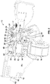
- a toy launch apparatus 10 is generally seen to simulate the shape of a gun and includes a rapid fire toy launch apparatus employing projectile feeding magazine storage, anti-jamming loading and launching mechanisms including a dart feeding magazine combination with a dart funnel 24 for at least one dart manually fed into the funnel.
- a dart feeding magazine combination with a dart funnel 24 for at least one dart manually fed into the funnel.
- the loading mechanism may be positioned at the open end of an inserted magazine with a stuffer mechanism that penetrates a dart magazine receiving a series of dart projectiles for rapidly loading into the magazine and firing from the apparatus without mis-fed darts jamming up either the dart magazine or launcher structures.
- the launch apparatus 10 includes a housing assembly 12 generally shaped like as a toy blaster or dart launcher which includes a loading slot 14 into which a dart magazine 16 is inserted, as seen in FIG. 1 .
- the described apparatus and methods facilitate rapidly receiving toy projectiles, storage with firing toy projectile loading and launch structures employing a feeding/magazine storage mechanism including a simple and nearly continuous dart feeding magazine receiving each dart into and from the magazine storage further employing launch elements advancing projectiles into an energy generating mechanism for rapidly firing darts from the toy apparatus. While the dart magazine 16 or drum is removable from the launch apparatus 10 includes a housing assembly 12, this load feature is achieved as loading darts to the apparatus 10 without having to remove the dart magazine 16.
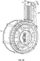
- the dart magazine 16 as shown in FIGS. 1-3B , includes a machine gun type magazine holding 30 or so darts 17, but can also include a straight rectangular magazine holding 6-18 darts 17, etc., as seen in FIG. 3C .
- each dart 17 has a sidewall, a forward tip 19, a first end 17a, a second end 17b, and a rear advancing surface 17c.
- other variations of known dart magazines designed to snap into the slot 14 of the housing assembly 12 and advance darts into the toy launch apparatus 10 are contemplated.
- the machine gun type dart magazine 16 holds 30 or more darts in a circular drum and advances retained darts to an open end 18, as seen in FIG. 3B .
- a straight rectangular portion 23, extends from the circular drum and includes the open end 18 for fitting the machine gun magazine into the slot 14 of the toy launch apparatus 10.
- the dart magazine 16 which holds a various number of darts from 6-18, as seen in FIG. 3C , is entirely straight and generally rectangular in shape 16 and also advances retained darts 17 toward the open end 18.
- the rectangular magazine 16, as seen in FIG. 3C is interchangeable with the machine gun magazine and also snaps into slot 14 of the toy launch apparatus 10 at the open end 18 of the magazine.
- a dart advancing mechanism 15 within the magazine creates a force to bias the retained darts 17 toward the open end 18, in both the magazine gun magazine and the straight rectangular shaped magazine.
- a pair of magazine sensor micro switches 43 and 45 are employed for detecting the presence and type of inserted magazine 16.
- the top micro switch 43 as illustrated in FIG. 3A functions both as a power switch to the electronic circuitry to the launch apparatus 10 and the micro switch 43 also detects when a when dart magazine 16 is inserted in order to detect magazine presence at the slot 14.
- the lower micro switch 45 is used to detect a type of inserted magazine 16 by a detecting a detent or notch 74 in the dart magazine 16 which indicates that the inserted magazine 16 is a 30 round magazine.
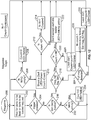
- FIGS. 11-14 illustrate loading logic for dart intake so as to control and monitor the darts supplied. Additionally LED light status, LEDs mounted on the launcher apparatus 10 not show, and the light indicators may be used to indicate a number of conditions.
- a micro switch and/ or a sensor limit stuffer home switch may be provided as an infrared sensor IR (infra-red) beam sensing with a check cycle to monitor the time it takes to fill the dart into the magazine and launch apparatus 10 conditions. Using the IR the launch apparatus 10 determines when the drum is empty and via a light color can give feed back to the user that the drum is empty (Solid Yellow).
- IR infra-red
- the launch apparatus 10 determines when a dart is in position to be fired. Determining this can govern the driving of the pusher to only push when a dart is ready reducing the likelihood of jams. Via the light colors the launch apparatus 10 can let the user know when the system is ready (Green). Using the home switch for the pusher the launch apparatus 10 can determine when the pusher does not return home and assumes it has jammed and alert the user to the presence of a jam via the red color (Solid Red). If the jam door is open the firing is disabled until it is closed (Solid Red). As described earlier using the home switch for the suffer the launch apparatus 10 can monitor the time it takes to fill the clip and if not completed in a designated amount of time let the user know the drum/clip is in a full state via the lights (blinking yellow).
- the Magazine/Drum inserted in blaster the launch apparatus 10 starting at step 100.
- the decision block determines if the drum is empty.
- the flow chart proceeds to FIG. 14 for Drum Logic with known count.
- the decision block determines if the drum is full.
- the dart Count unknown, is neither empty nor full, then at step 118, to drum 30 count unknown, the flow chart proceeds to FIG. 13 for Drum Logic with unknown count.
- the decision block determines if the magazine is full.
- the flow chart proceeds to wait for darts to be fired or darts to be loaded request.
- the flow chart proceeds for decision block: is trigger pressed?
- the flow chart proceeds for decision block: is magazine empty?
- Is Count > N?
- Is Count > N?
- Don't accept dart into loader, and LED blinking yellow.
- step 300 drum 30 count known, the flow chart proceeds at step 302, wait for darts to be fired or darts to be loaded request.
- step 304 the flow chart proceeds for decision block: is trigger pressed?
- step 306 the flow chart proceeds for decision block: is magazine empty?
- Is Count 0 Yes/No?
- At 320 Is magazine empty?
- At 322, Don't accept dart into loader, and LED Blinking Yellow.
- Load dart, and with decision step 326 determine if Full drum magazine is detected?
- step 328 Re-try dart stuffing, and with decision step 330 determine if Full drum magazine is detected?
- the flow chart proceeds for decision block: is magazine empty?
- the flow chart proceeds to wait for darts to be fired or darts to be loaded request.
- step 404 Was a dart fired?
- the flow proceeds for decision block: is magazine empty?
- the open end 18 of the machine gun magazine is essentially identical to the open end 18 of the entirely straight and rectangular magazine, as seen in FIG. 3C , and both the machine gun magazine and the rectangular magazine, as seen in FIGS. 3D and 3E , respectively, each include a pair of retaining lips 20 at the open end 18.
- Each retaining lip 20 extends from an opposite side of the open end 18 of the magazine, with the retaining lips slightly curving toward each other, as seen in FIGS. 3D and 3E .
- the generally C shaped retaining lips together define a retaining space or open compartment 21 for retaining an uppermost dart 17 in the magazine.
- the dart magazine 16 thus inserted into the slot 14 of the toy launch apparatus 10 of the housing assembly 12 has its open end 18 positioned upwardly therein.
- the lips 20 do not touch each other as they extend and curve beyond the open end 18 leaving a gap 20a between distal ends of the two retaining lips 20.
- the uppermost dart 17 in the magazine slightly bulges through the gap 20a until the magazine is inserted into the housing assembly 12, where the feeding/ dart funnel 24 urges the dart 17 from the retaining lips, as discussed in further detail below.
- the dart advancing mechanism 15 creates the force that bulges the uppermost dart 17 into the gap between the retaining lips 20.
- the dart advancing mechanism 15 advances the retained darts through the magazine and the retaining lips 20 prevent the dart advancing mechanism 15 from pushing the uppermost dart out of the open end of the magazine.
- the biased dart advancing mechanism thus urges darts in the dart magazine toward the open end of the dart magazine, the biased dart advancing mechanism in the dart magazine urging darts therein at the dart sidewall.
- the dart advancing mechanism 15 can include a spring biased platform 22, as seen in FIG. 3C , secured to an end of the magazine 16 opposite the open end 18.
- the secured spring urges the platform toward the open end 18 and advances darts 17 loaded into the magazine clip toward the open end, as seen in FIG. 3C .
- the retaining lips 20, as seen in FIG. 3D prevent the spring biased platform 22 from advancing the loaded/retained darts from the magazine until the magazine is inserted into the toy launch apparatus 10 and readied for launching, as discussed in more detail below.
- the darts 17 are generally manufactured from a foam material.
- the dart tip 19 is coupled at the first end 17a of the dart 17 and a rear advancing surface 17c is included at the second end 17b.
- the dart tip 19 is generally manufactured from a flexible plastic material and the dart tip 19 is generally heavier in weight than the dart 17 (sidewall tubular body) which is manufactured from foam.
- a continuous feeding/dart funnel 24, as seen in FIGS. 2-3A is coupled to the housing assembly 12 adjacent the inserted magazine 16 and extends into the dart magazine at the open end 18 for releasing darts from the magazine and feeding darts into an energy generating mechanism without darts jamming up in the launcher.
- a sensor limit intake detector switch 30 is used to detect the presence of an inserted dart, as seen in FIGS. 2-3A , and 7 , is depressed by a user and activates the energy generating mechanism 32 which drives intake motors.
- the intake detector switch 30 is an electromechanical switch for detecting the at least one dart being manually fed into the dart funnel.
- the intake energy generating mechanism 42 includes two opposed rotatable intake wheels, 26 and 28 which engage and advance darts therebetween coupled to an axle 32 and 34, respectively, with each, or gears driven for rotation about their axle 32 and 34 drive rotation of intake wheels 26 and 28, (or alternatively first and second gears) 26 and 28, respectively, are positioned in parallel relationship to one another respectively for creating a feeding intake force frictionally applied to the dart as the dart is engaged by wheel surfaces on each of the opposed rotatable intake wheels 26 and 28.
- This magazine loading mechanism is positioned in the housing 12 intermediate the funnel 24 and the dart retaining lips 20 at the open end 18 of the inserted magazine for receiving the at least one dart from the funnel for loading at the open end 18 of the inserted magazine between the dart retaining lips 18.
- the rotating wheels impart sufficient energy to the dart to draw the dart into the toy launch apparatus 10 through the feeding/ dart funnel 24.
- motor 51 is contained within drive intake wheel 26 and intake motor 53 is contained within drive intake wheel 28, such that activated intake motor 51 drives rotation of intake wheel 26 and activated motor 53 drives rotation of wheel 28.
- the magazine loading mechanism employs intake energy generating mechanism with rotatable intake wheels to engage the at least one dart from the funnel for loading at the open end of the inserted magazine between the dart retaining lips.
- the intake energy generating mechanism uses the intake detector switch 30 for detecting at least one dart manually fed into the dart funnel 24.
- One or more gears of the gear train 36 ride on second axle 34 adjacent second intake wheel 28, driving rotation of second wheel 28 in a continuous fashion as long as motor 38 is activated drawing darts into the toy launch apparatus 10 integral with the continuous feeding/dart funnel 24, advancing the dart into the energy projecting mechanism.
- the feeding/dart funnel 24, as seen in FIGS. 3A and 5-7 provides a positioning and timing with a dart intake switch in funnel 24 until dart tip hits stuffer activation lever switch at 46 stuffer driver limit switch indicates the dart has traveled in and is positioned to be stuffed, then a stuffer activation switch, referenced at the right of reference numeral 46.
- stuffer home IR switch checks cycle to monitor the time it takes to fill the dart into the magazine and launch apparatus 10 as discussed above in connection with the Loading Logic flow charts of FIGS. 11-14 .
- the home switch will monitor the time the stuffer mechanism 48 is actively trying to load a dart.
- the stuffer mechanism 48 takes more than a designated amount of time to get "home” the magazine is assumed to be full, also sensing for over-travel, so as to avoid overfilling based on the home check cycle indicating the magazine is filed or full magazine clip loading detection.
- the intake switch in funnel 24 is disabled to ensure no further darts are supplied, and prevent overfilling of the magazine.
- the feeding/dart funnel 24 is designed to reliably release the uppermost dart from the retaining lips of the inserted magazine and simultaneously time the advancement of the released dart into the energy generating mechanism. In the present described embodiment, the dart funnel 24 shown in FIG.
- the lever switch at 46 stuffer driver limit switch operates with a stuffer mechanism 48 limiting operation under a dart count using the switch 46 as each dart tip is detected.
- the switch 46 is coupled to the housing above the inserted magazine 16, with the stuffer mechanism 48 for penetrating the dart retaining lips 20 to stuff the at least one dart 17 at the dart sidewall from between the dart retaining lips for loading into the magazine.
- a stuffer motor 64 operates a reciprocating structure 66 through rack gears structures to reciprocate stuffer mechanism 48. Accordingly, the inserted magazine 16 receives a series of darts 17 loaded into the dart magazine 16.
- the pusher element 40 advances the darts from the magazine 16 with the energy generating mechanism timed for advancing the dart 17 into the dart launching mechanism forward the inserted magazine, and advances the darts only when the uppermost dart is correctly positioned for launching from the launch apparatus thus preventing the darts from being mis-fed into the energy generating mechanism and jamming up in the launcher.
- the pusher 40 is rearward the inserted magazine for pushing the dart rear advancing surface from between the dart retaining lips to advance the at least one dart into the forward launching mechanism.
- the pusher element 40 feeding mechanism actively push darts into an adjacent launching mechanism via an elongated arm biased into contact with a stack of darts lined up adjacent a drive wheel.
- the elongated arm biases the pusher element 40 into contact with the upper most dart of the stack and urges the lower most dart into the barrel adjacent the drive wheel urges the uppermost dart 17 into a releasing position while at the same time rotating protrusion elements which simultaneously time the advancement of the correctly positioned released darts.
- Darts 17 advance through the magazine as the advancing force from the dart advancing mechanism 15 is exerted against the darts loaded in the magazine.
- the energy generating mechanism is operatively in communication with each of the magazine loading, stuffer, and dart launching mechanisms.
- Darts pop up one by one into the retaining space or open compartment 21 between the retaining lips 20 before being advanced into the path of the energy generating mechanism.
- the heavier dart tip 19 is slightly tilted toward the magazine and lags behind the foam dart (body) when advanced into the compartment 21. If the dart is advanced or travels from the magazine while still in this slightly tilted position, the dart will not correctly feed into the energy generating mechanism and will jam up inside the launcher. This is especially likely to occur when darts are rapidly advanced into the energy generating mechanism from the dart magazine for rapid fire launching of darts from the toy.
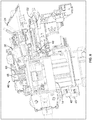
- FIG. 5 shows a cross-section view of a toy launch apparatus 10 with a dart magazine 16 inserted into the housing assembly 12 positioned with the launch apparatus 10 and including dart magazine loading, projectile launching structures and related mechanisms in the housing 12 thereof.
- FIGS. 6 and 7 has the feeding/magazine storage structures for dart magazine loading and following structure for firing projectiles from the magazine 16, where the magazine loading mechanism 46 is positioned in the housing intermediate the funnel 24 and the inserted dart magazine 16 for receiving darts 17 to the magazine open end described above.
- Such feeding/anti-jamming mechanisms provide reliable positioning and timing of darts advanced from the magazine to the feeding/anti-jamming mechanism, eliminating darts misfiring from the toy launch apparatus.
- the feeding/anti-jamming mechanism is automatically designed to wait until darts are correctly positioned before feeding the darts into the energy generating mechanism, while at the same time continuously running the mechanism.
- the reciprocating pusher element 40 is uniquely designed to both run continuously to urge the uppermost dart to a releasing position, and also essentially wait to feed darts into the energy generating mechanism until the uppermost dart in the magazine is positioned.
- the pusher element 40 advances the dart 17 at its rear advancing surface 17c without prematurely advancing it into the energy generating mechanism, with the pusher element 40 advancing a dart 17 residing between the dart retaining lips 20 of the magazine 16, advancing the dart away from the lips 20 at the foam dart body 17 with the forward dart tip 19 for advancement into the energy generating mechanism. Additionally the pusher element 40 extends to advance the positioned the dart 17 from the rear advancing surface 17c accessible to the pusher element 40. With the dart 17 correctly positioned, the pusher element 40 will engage the rear advancing surface 17c of the dart to push and advance the dart into the energy generating mechanism.
- a first trigger 50 is depressed by a user and activates both launch motors 51 and 53 which drive the energy generating mechanism 52.
- the energy generating mechanism 52 includes two opposed rotatable accelerator launch wheels, 54 and 56 which engage and advanced darts there between.
- Launch motors 51 and 53 drive rotation of launch wheels 54 and 56, respectively, creating a launching force frictionally applied to the dart as the dart engages a wheel surface on each of the opposed rotatable wheels.
- the rotating wheels impart sufficient energy to the dart to launch the dart from the toy launch apparatus.
- launch motor 51 is contained within drive launch wheel 54 and launch motor 53 is contained within drive launch wheel 56, such that activated launch motor 51 drives rotation of launch wheel 54 and activated launch motor 53 drives rotation of launch wheel 56.
- a second trigger 58 which activates a second launch motor 38 which rotates the feeding/dart funnel 24.
- the second launch motor 38 is disposed within the housing 12 and positioned behind a part of the housing, as seen in FIG. 2 .
- Reciprocating pusher element 40 about wheels 26 and 28. The pusher element 40 is advanced into the inserted magazine and with the pusher element 40 of the pusher element gliding along the uppermost dart residing in compartment 21 and urging the uppermost dart away from contact with the retaining lips 20 and into a releasing position.
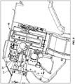
- FIGS. 8 , 9 and 10 show the dart loading employing the internal magazine loading mechanism 46 positioned in the housing where the magazine loading mechanism with the dart retaining lips 20 at the open end of the inserted magazine receives at least one dart for loading at the open end of the inserted magazine between the dart retaining lips 20, and a stuffer mechanism 48 is coupled to the housing 12 above the inserted magazine 16 for penetrating the dart retaining lips 16 to stuff the at least one dart 17 at the dart sidewall from between the dart retaining lips 20 for loading into the magazine 16, the inserted magazine 16 thusly receiving a series of darts 17 loaded into the dart magazine, with the inserted dart magazine thereunder.
- the reciprocating stuffer structure 66 is provided including rack gears structures with stuffer motor 64 operable to reciprocate stuffer mechanism 48 up and down to stuff the darts 17 between and into the dart retaining lips 20 for serially loading into the magazine 16, receiving a series of darts 17 loaded, with the stuffer mechanism 48 with the reciprocating actions for loading the darts 17'/ 17" as shown in FIG. 10 into the dart magazine 16.
- a stuffer sensor limit micro switch 68 is employed for detecting at least one dart 17 at the inserted magazine 16 between the dart retaining lips to limit operation of the stuffer motor, the stuffer sensor limit switch 68 is provided as a limit micro switch, at the forward tip 19 of the dart 17 resting at the open end 18 of the magazine 16 between the dart retaining lips 20 identifies the ready to fire position. There is a check cycle which will monitor the time it takes to fill the dart into the magazine. Once full the intake switch will be disabled and this will prevent overfilling of the magazine. In an alternate embodiment an infrared sensor may be used for over-travel or full magazine clip loading detection to ensure, sensing of the forward tip 19 for the ready to fire position.
- a second limit switch 70 is disposed within the slot 14 for capturing the inserted dart magazine is designed to sense and operate as closed/inactivated when a dart magazine is inserted into slot 14 allowing power to launch motor 38 and switch 70 is open/activated to cut off power to launch motor 38 when dart magazine 16 is removed from slot 14.
- a soft barrier 72 is disposed at the housing 12 between the energy generating mechanism 52 and the feeding/dart funnel 24 in the pathway the dart 17 travels from the dart magazine to the energy generating mechanism, as a safety mechanism.
- the soft barrier 72 is manufactured from a silicone material with a perforated opening and is supported by a frame, however, it is also contemplated that the soft barrier can be manufactured from other materials such as plastic which is flexible enough for a dart to penetrate a perforated opening, but rigid enough to prevent unintended objects from entering the energy generating mechanism.
- the soft barrier 72 provides just enough resistance to prevent a projectiles less than two inches in length from getting into the energy generating mechanism.
- Object less that two inches in length could be a choking hazard and are undesirable projectiles to be fired from a toy launch apparatus.
- the soft barrier 72 may prevent unintended and improvised projectiles from getting into the energy generating mechanism and being fired from the toy launch apparatus.
- the distance between the axle 32 of the first gear 26 and the entrance into the energy generating mechanism is desirable to keep the distance between the axle 32 of the first gear 26 and the entrance into the energy generating mechanism to 51mm or more, as a safety precaution to keep small projectiles (typically less than two inches) out of the energy generating mechanism and fired from the toy launch apparatus. Projectiles less than 51mm will not be long enough to stretch the gap between the feeding/anti-jamming mechanism and the energy generating mechanism, and will fall to the interior of the housing 12 without ever being fired from the toy launch apparatus.
Landscapes
- Engineering & Computer Science (AREA)
- General Engineering & Computer Science (AREA)
- Multimedia (AREA)
- Toys (AREA)
Claims (14)
- Appareil de lancement de fléchettes, comprenant :un ensemble boîtier ;un magasin de fléchettes inséré dans l'ensemble boîtier, le magasin inséré ayant une extrémité ouverte comprenant des lèvres de retenue de fléchettes au niveau de l'extrémité ouverte ;un mécanisme d'avancement de fléchettes sollicité poussant des fléchettes dans le magasin de fléchettes vers l'extrémité ouverte du magasin de fléchettes, chaque fléchette comportant une paroi latérale, une pointe avant et une surface d'avancement arrière, le mécanisme d'avancement de fléchettes sollicité dans le magasin de fléchettes poussant des fléchettes à l'intérieur de celui-ci au niveau de la paroi latérale de fléchette ;un entonnoir à fléchettes sur l'ensemble boîtier pour au moins une fléchette à introduire dans l'entonnoir ;un mécanisme de chargement de magasin positionné dans le boîtier entre l'entonnoir et les lèvres de retenue de fléchettes au niveau de l'extrémité ouverte du magasin inséré pour recevoir l'au moins une fléchette de l'entonnoir aux fins de chargement au niveau de l'extrémité ouverte du magasin inséré entre les lèvres de retenue de fléchettes ;un mécanisme de bourrage couplé au boîtier au-dessus du magasin inséré pour pénétrer dans les lèvres de retenue de fléchettes afin de bourrer l'au moins une fléchette sur la paroi latérale de fléchette entre les lèvres de retenue de fléchettes aux fins de chargement dans le magasin, le magasin inséré recevant une série de fléchettes chargées dans le magazine de fléchettes ;un mécanisme de lancement de fléchettes dans le boîtier vers l'avant du magasin inséré ;un poussoir vers l'arrière du magasin inséré destiné à pousser l'au moins une fléchette sur la surface d'avancement arrière entre les lèvres de retenue de fléchettes afin de faire avancer l'au moins une fléchette dans le mécanisme de lancement vers l'avant ; etau moins un mécanisme de production d'énergie en communication avec chacun des mécanismes de chargement de magasin, de bourrage et de lancement de fléchettes.
- Appareil de lancement de fléchettes selon la revendication 1, dans lequel le mécanisme de chargement de magasin comprend un mécanisme de production d'énergie d'admission comportant des roues d'admission rotatives pour venir en prise avec l'au moins une fléchette de l'entonnoir pour le chargement à l'extrémité ouverte du magasin inséré entre les lèvres de retenue de fléchettes, dans lequel, de préférence, le mécanisme de production d'énergie d'admission comprend un moteur d'admission entraînant les roues d'admission rotatives, plus préférablement dans lequel le moteur d'admission entraîne la rotation d'au moins l'une des première et seconde roues d'admission.
- Appareil de lancement de fléchettes selon la revendication 2, dans lequel le mécanisme de production d'énergie d'admission comprend un commutateur de détection d'admission détectant au moins une fléchette introduite manuellement dans l'entonnoir à fléchettes, dans lequel, de préférence, le commutateur de détection d'admission est un commutateur électromécanique permettant de détecter l'au moins une fléchette manuellement introduite dans l'entonnoir à fléchettes.
- Appareil de lancement de fléchettes selon l'une quelconque des revendications précédentes, dans lequel le mécanisme de lancement de fléchettes comprend un moteur de lancement au niveau du boîtier pour entraîner la rotation d'au moins l'une des première et seconde roues de lancement, dans lequel, de préférence, le mécanisme de poussoir comprend une structure de poussoir à mouvement alternatif qui avance à partir de la surface d'avancement arrière pour faire avancer au moins l'une des fléchettes dans les roues de lancement du mécanisme de lancement de fléchettes.
- Appareil de lancement de fléchettes selon la revendication 4, dans lequel le mécanisme de poussoir comprend un moteur de poussoir au niveau du boîtier pour faire alterner la structure de poussoir alternative du mécanisme de poussoir afin de lancer une série de fléchettes à partir du magasin de fléchettes.
- Appareil de lancement de fléchettes selon l'une quelconque des revendications précédentes, dans lequel le mécanisme de bourrage comprend une structure de bourrage à mouvement alternatif avançant au niveau de la paroi latérale de fléchette entre les lèvres de retenue de fléchettes pour charger la série de fléchettes dans le magasin de fléchettes, dans lequel, de préférence, le mécanisme de bourrage comprend un moteur de bourrage au niveau du boîtier pour faire alterner la structure de bourrage alternative du mécanisme de bourrage afin de charger la série de fléchettes dans le magasin de fléchettes.
- Appareil de lancement de fléchettes selon la revendication 6, dans lequel le mécanisme de bourrage comprend un commutateur de limite de capteur de bourrage détectant au moins une fléchette au niveau du magasin inséré entre les lèvres de retenue de fléchettes pour limiter le fonctionnement du moteur de bourrage, dans lequel, de préférence, le commutateur de limite de capteur de bourrage comprend un micro-commutateur de limite.
- Appareil de lancement de fléchettes selon la revendication 1, dans lequel le mécanisme de chargement de magasin comprend un mécanisme de production d'énergie d'admission comportant des roues d'admission rotatives pour venir en prise avec l'au moins une fléchette provenant de l'entonnoir aux fins de chargement à l'extrémité ouverte du magasin inséré entre les lèvres de retenue de fléchettes ;dans lequel le mécanisme de bourrage comprend une structure de bourrage à mouvement alternatif avançant au niveau de la paroi latérale de fléchette entre les lèvres de retenue de fléchettes afin de charger la série de fléchettes dans le magasin de fléchettes ; etdans lequel le mécanisme de poussoir comprend une structure de poussoir alternative qui avance de la surface d'avancement arrière dans les roues de lancement du mécanisme de lancement de fléchettes.
- Appareil de lancement de fléchettes selon la revendication 8, comprenant au moins un mécanisme de production d'énergie en communication avec chacun des mécanismes de chargement de magasin, de bourrage et de lancement de fléchettes, comprenant en outre :un moteur d'admission entraînant au moins l'une des roues d'admission rotatives du mécanisme de production d'énergie d'admission ;un moteur de bourrage au niveau du boîtier pour faire alterner la structure de bourrage à mouvement alternatif du mécanisme de bourrage aux fins de chargement de la série de fléchettes dans le magasin de fléchettes ;un moteur de poussoir au niveau du boîtier pour faire alterner la structure de poussoir alternative du mécanisme de poussoir afin de lancer une série de fléchettes à partir du magasin de fléchettes ; etun moteur de lancement au niveau du boîtier pour entraîner la rotation d'au moins l'une des première et seconde roues de lancement, le mécanisme de production d'énergie coordonnant chacun des mécanismes de chargement de magasin, de bourrage et de lancement de fléchettes afin de recevoir et de lancer la série de fléchettes.
- Appareil de lancement de fléchettes selon la revendication 9, dans lequel le mécanisme de production d'énergie d'admission comprend un commutateur de détection d'admission détectant au moins une fléchette introduite manuellement dans l'entonnoir à fléchettes, le commutateur de détection d'admission détectant l'au moins une fléchette introduite manuellement dans l'entonnoir à fléchettes.
- Appareil de lancement de fléchette selon la revendication 9 ou 10, dans lequel le mécanisme de bourrage comprend un commutateur de limite de capteur de poussoir détectant au moins une fléchette au niveau du magasin inséré entre les lèvres de retenue de fléchettes pour limiter le fonctionnement du moteur de bourrage.
- Procédé de lancement de fléchettes, comprenant :l'insertion d'une extrémité ouverte d'un magasin de fléchettes, l'extrémité ouverte du magasin de fléchettes comprenant des lèvres de retenue de fléchettes au niveau de l'extrémité ouverte insérées dans un ensemble boîtier et comportant un entonnoir à fléchettes sur l'ensemble boîtier pour qu'au moins une fléchette soit introduite dans l'entonnoir, chaque fléchette comprenant une paroi latérale, une pointe avant et une surface d'avancement arrière ;le positionnement d'un mécanisme de chargement de magasin dans le boîtier entre l'entonnoir et les lèvres de retenue de fléchettes à l'extrémité ouverte du magasin inséré pour recevoir l'au moins une fléchette de l'entonnoir pour le chargement à l'extrémité ouverte du magasin inséré entre les lèvres de retenue de fléchettes, dans lequel le mécanisme de chargement de magasin comprend un mécanisme de production d'énergie d'admission avec des roues d'admission rotatives pour venir en prise avec l'au moins une fléchette provenant de l'entonnoir aux fins de chargement à l'extrémité ouverte du magasin inséré entre les lèvres de retenue de fléchettes ;la fourniture d'un mécanisme de bourrage couplé au boîtier au-dessus du magasin inséré pour pénétrer dans les lèvres de retenue de fléchettes pour bourrer l'au moins une fléchette sur la paroi latérale de la fléchette entre les lèvres de retenue de fléchettes pour le charger dans le magasin ;la sollicitation des fléchettes dans le magasin de fléchettes vers l'extrémité ouverte du magasin de fléchettes comportant un mécanisme d'avancement de fléchettes sollicité dans le magasin de fléchettes en poussant les fléchettes à l'intérieur de celui-ci au niveau de la paroi latérale de fléchette ;le positionnement d'un mécanisme de lancement de fléchettes dans le boîtier vers l'avant du magasin inséré ; etle positionnement d'un poussoir vers l'arrière du magasin inséré pour pousser l'au moins une fléchette sur la surface d'avancement arrière entre les lèvres de retenue de fléchettes pour faire avancer l'au moins une fléchette dans le mécanisme de lancement vers l'avant.
- Procédé de lancement de fléchette selon la revendication 12, dans lequel l'étape de fourniture de mécanisme de bourrage comprend un mouvement alternatif de la structure de bourrage aux fins de l'avancement au niveau de la paroi latérale de la fléchette entre les lèvres de retenue de fléchettes au fin du chargement de la série de fléchettes dans le magasin de fléchettes, le magasin inséré recevant une série de fléchettes chargées dans le magasin de fléchettes.
- Procédé de lancement de fléchettes selon la revendication 12 ou 13, fournissant au moins un mécanisme de production d'énergie en communication avec chacun des chargement de magasin, bourrage et lancement de fléchettes fournis, comprenant en outre les étapes de :fourniture d'un moteur d'admission entraînant au moins l'une des roues d'admission rotatives du mécanisme de production d'énergie d'admission ;de fourniture d'un moteur de bourrage au niveau du boîtier pour faire alterner la structure de bourrage à mouvement alternatif du mécanisme de bourrage afin de charger la série de fléchettes dans le magasin de fléchettes ;de fourniture d'un moteur de poussoir dans le boîtier pour faire alterner la structure de poussoir alternative du mécanisme de poussoir afin de lancer une série de fléchettes à partir du magasin de fléchettes ; etde fourniture d'un moteur de lancement dans le boîtier pour entraîner la rotation d'au moins l'une des première et seconde roues de lancement, le mécanisme de production d'énergie coordonnant chacun des mécanismes de chargement de magasin, de bourrage et de lancement de fléchettes afin de recevoir et de lancer la série de fléchettes.
Applications Claiming Priority (2)
| Application Number | Priority Date | Filing Date | Title |
|---|---|---|---|
| US201762551693P | 2017-08-29 | 2017-08-29 | |
| US16/105,546 US10488143B2 (en) | 2017-08-29 | 2018-08-20 | Rapid fire toy launch apparatus |
Publications (2)
| Publication Number | Publication Date |
|---|---|
| EP3450902A1 EP3450902A1 (fr) | 2019-03-06 |
| EP3450902B1 true EP3450902B1 (fr) | 2020-10-07 |
Family
ID=63442435
Family Applications (1)
| Application Number | Title | Priority Date | Filing Date |
|---|---|---|---|
| EP18191106.6A Active EP3450902B1 (fr) | 2017-08-29 | 2018-08-28 | Appareil de lancement de jouet à tir rapide |
Country Status (3)
| Country | Link |
|---|---|
| US (1) | US10488143B2 (fr) |
| EP (1) | EP3450902B1 (fr) |
| CN (1) | CN109420352B (fr) |
Cited By (2)
| Publication number | Priority date | Publication date | Assignee | Title |
|---|---|---|---|---|
| TWI790678B (zh) * | 2021-07-12 | 2023-01-21 | 怪怪貿易股份有限公司 | 玩具槍的多彈道式彈匣 |
| TWI790666B (zh) * | 2021-06-30 | 2023-01-21 | 怪怪貿易股份有限公司 | 可自動彈出彈匣的玩具槍及其彈匣裝置 |
Families Citing this family (10)
| Publication number | Priority date | Publication date | Assignee | Title |
|---|---|---|---|---|
| GB201805962D0 (en) * | 2018-04-11 | 2018-05-23 | Joukov Oleg | Automated toy dart launcher with motorized driven drum |
| US10845142B2 (en) * | 2018-07-02 | 2020-11-24 | Victor Flood | Methods, systems, apparatuses and devices for facilitating counting and displaying of an ammunition count of a magazine of a firearm |
| CN113767260B (zh) * | 2019-03-26 | 2024-04-02 | 孩之宝有限公司 | 玩具弹射件安全系统 |
| US11346624B2 (en) | 2019-10-07 | 2022-05-31 | Hasbro, Inc. | Projectile loading system for toy launcher and methods |
| US11243044B2 (en) * | 2020-05-05 | 2022-02-08 | Easebon Services Limited | Short projectile pistol with storage handle |
| BR112023015282A2 (pt) * | 2021-01-31 | 2023-11-14 | Liran Ganor | Projéteis de água e armas de brinquedo para os mesmos |
| CN113413621B (zh) * | 2021-06-30 | 2022-10-11 | 奥飞娱乐股份有限公司 | 一种弹链式发射器玩具 |
| US11953286B1 (en) * | 2021-07-09 | 2024-04-09 | Hasbro, Inc. | Rapid fire toy launch apparatus |
| US11859939B2 (en) * | 2022-03-16 | 2024-01-02 | Crosman Corporation | Air gun with automatic cocking |
| CN115089979B (zh) * | 2022-07-22 | 2023-09-29 | 广州城市理工学院 | 一种供料发射装置 |
Family Cites Families (35)
| Publication number | Priority date | Publication date | Assignee | Title |
|---|---|---|---|---|
| FR382142A (fr) | 1907-04-08 | 1908-01-30 | Wilhelm Stappenbeck | Aiguille à larder |
| BE343831A (fr) | 1926-07-09 | |||
| DE554199C (de) | 1931-06-18 | 1932-07-06 | Waffenfabrik Solothurn A G | Vorrichtung zum Fuellen von Patronenmagazinen |
| US2737942A (en) | 1953-05-11 | 1956-03-13 | Horowitz Harry | Toy guns |
| US2783570A (en) * | 1954-04-29 | 1957-03-05 | William R Kunz | Magazine charger for firearms |
| US2908097A (en) * | 1957-11-19 | 1959-10-13 | Harold D Allyn | Firearm magazine construction |
| US3990426A (en) | 1975-07-22 | 1976-11-09 | Gilbert Stokes | Tennis ball throwing machine |
| US4841945A (en) | 1987-05-07 | 1989-06-27 | Braden Victor K | Automatic tennis ball feeding and serving apparatus |
| IT1217073B (it) * | 1987-06-11 | 1990-03-14 | Ferri Giampiero | Caricatore per munizioni a striscia con alloggiamento prismatico rettangolare e dente scorrevole di estrazione. |
| JP3002139U (ja) * | 1994-03-18 | 1994-09-20 | 株式会社トイボックス | 円盤発射玩具 |
| CN2234294Y (zh) * | 1995-04-01 | 1996-09-04 | 吕志辉 | 玩具连发枪 |
| US5669171A (en) * | 1996-09-17 | 1997-09-23 | Sally; Thomas A. | Speedloader for magazines of automatic rifles |
| US6488019B2 (en) * | 1999-02-26 | 2002-12-03 | Thomas G. Kotsiopoulos | Feeder for a paintball gun |
| US6220237B1 (en) * | 1999-07-30 | 2001-04-24 | Johnson Research & Development Company, Inc. | Compressed air toy gun |
| US6408837B1 (en) * | 1999-09-13 | 2002-06-25 | Johnson Research & Development Co. | Toy gun with magazine |
| US20020166551A1 (en) * | 2001-05-11 | 2002-11-14 | Lee Chung Hon | Toy projectile launcher |
| CN2523480Y (zh) * | 2001-12-06 | 2002-12-04 | 葛亚娟 | 全塑旋转式彩花发射器 |
| US7108576B2 (en) * | 2004-02-13 | 2006-09-19 | Poof Products, Inc. | Foam projectile exhibiting an illuminating element |
| US7051727B2 (en) * | 2004-10-25 | 2006-05-30 | Wen-Long Wu | Shooting mechanism of shot repeater target toy |
| US7841327B2 (en) * | 2007-09-15 | 2010-11-30 | Mattel, Inc. | Toy projectile launcher |
| HK1115715A2 (en) | 2007-10-11 | 2008-12-05 | Buzz Bee Toys Co Ltd | Toy gun |
| US8402958B2 (en) * | 2009-08-21 | 2013-03-26 | Hasbro, Inc. | Toy dart magazine apparatus |
| US9027541B2 (en) * | 2010-08-11 | 2015-05-12 | Easebon Services Limited | Toy launcher for launching projectiles and methods thereof |
| US8353277B2 (en) | 2010-08-11 | 2013-01-15 | Easebon Services Limited | Toy launcher for launching projectiles and methods thereof |
| US8484874B2 (en) * | 2011-04-09 | 2013-07-16 | Raymond Kyungjune Kim | Systems and methods for receiving and loading cartridges in bulk |
| CN102772905A (zh) * | 2011-05-13 | 2012-11-14 | 威霸玩具(香港)有限公司 | 探测玩具枪的子弹腔中子弹的装置及方法 |
| US8955503B2 (en) * | 2011-11-03 | 2015-02-17 | Spin Master Ltd. | Toy projectile launcher and projectile thereof |
| US20130312722A1 (en) | 2012-05-25 | 2013-11-28 | Derrick Douglas Price | Device for shooting paper currency |
| US9097476B2 (en) * | 2012-05-25 | 2015-08-04 | Hasbro, Inc. | Projectile launcher with rotatable clip connector |
| WO2015013614A1 (fr) * | 2013-07-26 | 2015-01-29 | Mattel Inc. | Lanceur de projectile et son procédé de fonctionnement |
| CN204177283U (zh) | 2014-10-23 | 2015-02-25 | 陈沛得 | 一种玩具枪 |
| US9429385B1 (en) * | 2015-02-11 | 2016-08-30 | Scott William Allen | Drum magazine for loading paintballs and shaped projectiles into a magazine-fed firearm |
| JP3199723U (ja) * | 2015-03-21 | 2015-09-10 | 小原 昭彦 | ペットボトルの蓋及びプラスチック円板飛ばしゴム銃 |
| US9958230B1 (en) * | 2015-12-22 | 2018-05-01 | Hasbro, Inc. | Rapid fire toy launch apparatus |
| IT201700049374A1 (it) * | 2017-05-08 | 2018-11-08 | Mec Gar Srl | Dispositivo complemento modulare multifunzione per caricatore d'arma da fuoco |
-
2018
- 2018-08-20 US US16/105,546 patent/US10488143B2/en active Active
- 2018-08-28 EP EP18191106.6A patent/EP3450902B1/fr active Active
- 2018-08-29 CN CN201810997401.7A patent/CN109420352B/zh active Active
Non-Patent Citations (1)
| Title |
|---|
| None * |
Cited By (2)
| Publication number | Priority date | Publication date | Assignee | Title |
|---|---|---|---|---|
| TWI790666B (zh) * | 2021-06-30 | 2023-01-21 | 怪怪貿易股份有限公司 | 可自動彈出彈匣的玩具槍及其彈匣裝置 |
| TWI790678B (zh) * | 2021-07-12 | 2023-01-21 | 怪怪貿易股份有限公司 | 玩具槍的多彈道式彈匣 |
Also Published As
| Publication number | Publication date |
|---|---|
| CN109420352B (zh) | 2022-05-31 |
| US10488143B2 (en) | 2019-11-26 |
| EP3450902A1 (fr) | 2019-03-06 |
| CN109420352A (zh) | 2019-03-05 |
| US20190063865A1 (en) | 2019-02-28 |
Similar Documents
| Publication | Publication Date | Title |
|---|---|---|
| EP3450902B1 (fr) | Appareil de lancement de jouet à tir rapide | |
| US9958230B1 (en) | Rapid fire toy launch apparatus | |
| US6109252A (en) | Projectile feed system | |
| US10871343B2 (en) | Easy loading toy projectile launcher | |
| US5056252A (en) | Firearm magazine | |
| WO2010085734A1 (fr) | Projectile non mortel et procédé de production de celui-ci | |
| US9103623B2 (en) | Cartridge gas energized gun for arrows, darts and the like | |
| US10876809B1 (en) | Quick start projectile launcher and methods | |
| US11340037B1 (en) | Easy loading toy projectile launcher | |
| US10648763B2 (en) | Easy loading toy projectile launcher | |
| US3563132A (en) | Grenade launcher | |
| CN114719673A (zh) | 电磁发射器连续上弹系统及方法 | |
| KR100429662B1 (ko) | 소화기용탄피방출장치 | |
| US2453786A (en) | Feed mechanism for rapid-fire guns | |
| US5027541A (en) | Magazine loaded firearm | |
| US5284081A (en) | Lightweight grenade launcher | |
| US3319523A (en) | Drum cartridge feeding mechanism | |
| US5317951A (en) | Cartridge non-ramping feed mechanism for firearms | |
| WO2022127947A1 (fr) | Système de mise à feu pneumatique | |
| JPH0535358B2 (fr) | ||
| US2792761A (en) | Gun feeding mechanism | |
| US3802313A (en) | Machine gun having dual feeding means for selectively feeding cartridges | |
| US11953286B1 (en) | Rapid fire toy launch apparatus | |
| JPH03294793A (ja) | 装薬供給装置 | |
| CN216523393U (zh) | 一种新型抛壳激光训练模型枪 |
Legal Events
| Date | Code | Title | Description |
|---|---|---|---|
| PUAI | Public reference made under article 153(3) epc to a published international application that has entered the european phase |
Free format text: ORIGINAL CODE: 0009012 |
|
| STAA | Information on the status of an ep patent application or granted ep patent |
Free format text: STATUS: THE APPLICATION HAS BEEN PUBLISHED |
|
| AK | Designated contracting states |
Kind code of ref document: A1 Designated state(s): AL AT BE BG CH CY CZ DE DK EE ES FI FR GB GR HR HU IE IS IT LI LT LU LV MC MK MT NL NO PL PT RO RS SE SI SK SM TR |
|
| AX | Request for extension of the european patent |
Extension state: BA ME |
|
| STAA | Information on the status of an ep patent application or granted ep patent |
Free format text: STATUS: REQUEST FOR EXAMINATION WAS MADE |
|
| 17P | Request for examination filed |
Effective date: 20190906 |
|
| RBV | Designated contracting states (corrected) |
Designated state(s): AL AT BE BG CH CY CZ DE DK EE ES FI FR GB GR HR HU IE IS IT LI LT LU LV MC MK MT NL NO PL PT RO RS SE SI SK SM TR |
|
| GRAP | Despatch of communication of intention to grant a patent |
Free format text: ORIGINAL CODE: EPIDOSNIGR1 |
|
| STAA | Information on the status of an ep patent application or granted ep patent |
Free format text: STATUS: GRANT OF PATENT IS INTENDED |
|
| INTG | Intention to grant announced |
Effective date: 20200318 |
|
| GRAS | Grant fee paid |
Free format text: ORIGINAL CODE: EPIDOSNIGR3 |
|
| GRAA | (expected) grant |
Free format text: ORIGINAL CODE: 0009210 |
|
| STAA | Information on the status of an ep patent application or granted ep patent |
Free format text: STATUS: THE PATENT HAS BEEN GRANTED |
|
| AK | Designated contracting states |
Kind code of ref document: B1 Designated state(s): AL AT BE BG CH CY CZ DE DK EE ES FI FR GB GR HR HU IE IS IT LI LT LU LV MC MK MT NL NO PL PT RO RS SE SI SK SM TR |
|
| REG | Reference to a national code |
Ref country code: GB Ref legal event code: FG4D |
|
| REG | Reference to a national code |
Ref country code: CH Ref legal event code: EP Ref country code: AT Ref legal event code: REF Ref document number: 1321612 Country of ref document: AT Kind code of ref document: T Effective date: 20201015 |
|
| REG | Reference to a national code |
Ref country code: DE Ref legal event code: R096 Ref document number: 602018008467 Country of ref document: DE |
|
| REG | Reference to a national code |
Ref country code: IE Ref legal event code: FG4D |
|
| REG | Reference to a national code |
Ref country code: NL Ref legal event code: MP Effective date: 20201007 |
|
| REG | Reference to a national code |
Ref country code: AT Ref legal event code: MK05 Ref document number: 1321612 Country of ref document: AT Kind code of ref document: T Effective date: 20201007 |
|
| PG25 | Lapsed in a contracting state [announced via postgrant information from national office to epo] |
Ref country code: RS Free format text: LAPSE BECAUSE OF FAILURE TO SUBMIT A TRANSLATION OF THE DESCRIPTION OR TO PAY THE FEE WITHIN THE PRESCRIBED TIME-LIMIT Effective date: 20201007 Ref country code: PT Free format text: LAPSE BECAUSE OF FAILURE TO SUBMIT A TRANSLATION OF THE DESCRIPTION OR TO PAY THE FEE WITHIN THE PRESCRIBED TIME-LIMIT Effective date: 20210208 Ref country code: FI Free format text: LAPSE BECAUSE OF FAILURE TO SUBMIT A TRANSLATION OF THE DESCRIPTION OR TO PAY THE FEE WITHIN THE PRESCRIBED TIME-LIMIT Effective date: 20201007 Ref country code: GR Free format text: LAPSE BECAUSE OF FAILURE TO SUBMIT A TRANSLATION OF THE DESCRIPTION OR TO PAY THE FEE WITHIN THE PRESCRIBED TIME-LIMIT Effective date: 20210108 Ref country code: NO Free format text: LAPSE BECAUSE OF FAILURE TO SUBMIT A TRANSLATION OF THE DESCRIPTION OR TO PAY THE FEE WITHIN THE PRESCRIBED TIME-LIMIT Effective date: 20210107 |
|
| REG | Reference to a national code |
Ref country code: LT Ref legal event code: MG4D |
|
| PG25 | Lapsed in a contracting state [announced via postgrant information from national office to epo] |
Ref country code: BG Free format text: LAPSE BECAUSE OF FAILURE TO SUBMIT A TRANSLATION OF THE DESCRIPTION OR TO PAY THE FEE WITHIN THE PRESCRIBED TIME-LIMIT Effective date: 20210107 Ref country code: LV Free format text: LAPSE BECAUSE OF FAILURE TO SUBMIT A TRANSLATION OF THE DESCRIPTION OR TO PAY THE FEE WITHIN THE PRESCRIBED TIME-LIMIT Effective date: 20201007 Ref country code: IS Free format text: LAPSE BECAUSE OF FAILURE TO SUBMIT A TRANSLATION OF THE DESCRIPTION OR TO PAY THE FEE WITHIN THE PRESCRIBED TIME-LIMIT Effective date: 20210207 Ref country code: PL Free format text: LAPSE BECAUSE OF FAILURE TO SUBMIT A TRANSLATION OF THE DESCRIPTION OR TO PAY THE FEE WITHIN THE PRESCRIBED TIME-LIMIT Effective date: 20201007 Ref country code: SE Free format text: LAPSE BECAUSE OF FAILURE TO SUBMIT A TRANSLATION OF THE DESCRIPTION OR TO PAY THE FEE WITHIN THE PRESCRIBED TIME-LIMIT Effective date: 20201007 Ref country code: ES Free format text: LAPSE BECAUSE OF FAILURE TO SUBMIT A TRANSLATION OF THE DESCRIPTION OR TO PAY THE FEE WITHIN THE PRESCRIBED TIME-LIMIT Effective date: 20201007 Ref country code: AT Free format text: LAPSE BECAUSE OF FAILURE TO SUBMIT A TRANSLATION OF THE DESCRIPTION OR TO PAY THE FEE WITHIN THE PRESCRIBED TIME-LIMIT Effective date: 20201007 |
|
| PG25 | Lapsed in a contracting state [announced via postgrant information from national office to epo] |
Ref country code: HR Free format text: LAPSE BECAUSE OF FAILURE TO SUBMIT A TRANSLATION OF THE DESCRIPTION OR TO PAY THE FEE WITHIN THE PRESCRIBED TIME-LIMIT Effective date: 20201007 Ref country code: NL Free format text: LAPSE BECAUSE OF FAILURE TO SUBMIT A TRANSLATION OF THE DESCRIPTION OR TO PAY THE FEE WITHIN THE PRESCRIBED TIME-LIMIT Effective date: 20201007 |
|
| REG | Reference to a national code |
Ref country code: DE Ref legal event code: R097 Ref document number: 602018008467 Country of ref document: DE |
|
| PG25 | Lapsed in a contracting state [announced via postgrant information from national office to epo] |
Ref country code: SM Free format text: LAPSE BECAUSE OF FAILURE TO SUBMIT A TRANSLATION OF THE DESCRIPTION OR TO PAY THE FEE WITHIN THE PRESCRIBED TIME-LIMIT Effective date: 20201007 Ref country code: EE Free format text: LAPSE BECAUSE OF FAILURE TO SUBMIT A TRANSLATION OF THE DESCRIPTION OR TO PAY THE FEE WITHIN THE PRESCRIBED TIME-LIMIT Effective date: 20201007 Ref country code: CZ Free format text: LAPSE BECAUSE OF FAILURE TO SUBMIT A TRANSLATION OF THE DESCRIPTION OR TO PAY THE FEE WITHIN THE PRESCRIBED TIME-LIMIT Effective date: 20201007 Ref country code: LT Free format text: LAPSE BECAUSE OF FAILURE TO SUBMIT A TRANSLATION OF THE DESCRIPTION OR TO PAY THE FEE WITHIN THE PRESCRIBED TIME-LIMIT Effective date: 20201007 Ref country code: RO Free format text: LAPSE BECAUSE OF FAILURE TO SUBMIT A TRANSLATION OF THE DESCRIPTION OR TO PAY THE FEE WITHIN THE PRESCRIBED TIME-LIMIT Effective date: 20201007 Ref country code: SK Free format text: LAPSE BECAUSE OF FAILURE TO SUBMIT A TRANSLATION OF THE DESCRIPTION OR TO PAY THE FEE WITHIN THE PRESCRIBED TIME-LIMIT Effective date: 20201007 |
|
| PLBE | No opposition filed within time limit |
Free format text: ORIGINAL CODE: 0009261 |
|
| STAA | Information on the status of an ep patent application or granted ep patent |
Free format text: STATUS: NO OPPOSITION FILED WITHIN TIME LIMIT |
|
| PG25 | Lapsed in a contracting state [announced via postgrant information from national office to epo] |
Ref country code: DK Free format text: LAPSE BECAUSE OF FAILURE TO SUBMIT A TRANSLATION OF THE DESCRIPTION OR TO PAY THE FEE WITHIN THE PRESCRIBED TIME-LIMIT Effective date: 20201007 |
|
| 26N | No opposition filed |
Effective date: 20210708 |
|
| PG25 | Lapsed in a contracting state [announced via postgrant information from national office to epo] |
Ref country code: IT Free format text: LAPSE BECAUSE OF FAILURE TO SUBMIT A TRANSLATION OF THE DESCRIPTION OR TO PAY THE FEE WITHIN THE PRESCRIBED TIME-LIMIT Effective date: 20201007 Ref country code: AL Free format text: LAPSE BECAUSE OF FAILURE TO SUBMIT A TRANSLATION OF THE DESCRIPTION OR TO PAY THE FEE WITHIN THE PRESCRIBED TIME-LIMIT Effective date: 20201007 |
|
| PG25 | Lapsed in a contracting state [announced via postgrant information from national office to epo] |
Ref country code: SI Free format text: LAPSE BECAUSE OF FAILURE TO SUBMIT A TRANSLATION OF THE DESCRIPTION OR TO PAY THE FEE WITHIN THE PRESCRIBED TIME-LIMIT Effective date: 20201007 |
|
| REG | Reference to a national code |
Ref country code: DE Ref legal event code: R119 Ref document number: 602018008467 Country of ref document: DE |
|
| REG | Reference to a national code |
Ref country code: CH Ref legal event code: PL |
|
| PG25 | Lapsed in a contracting state [announced via postgrant information from national office to epo] |
Ref country code: MC Free format text: LAPSE BECAUSE OF FAILURE TO SUBMIT A TRANSLATION OF THE DESCRIPTION OR TO PAY THE FEE WITHIN THE PRESCRIBED TIME-LIMIT Effective date: 20201007 |
|
| REG | Reference to a national code |
Ref country code: BE Ref legal event code: MM Effective date: 20210831 |
|
| PG25 | Lapsed in a contracting state [announced via postgrant information from national office to epo] |
Ref country code: LI Free format text: LAPSE BECAUSE OF NON-PAYMENT OF DUE FEES Effective date: 20210831 Ref country code: CH Free format text: LAPSE BECAUSE OF NON-PAYMENT OF DUE FEES Effective date: 20210831 |
|
| PG25 | Lapsed in a contracting state [announced via postgrant information from national office to epo] |
Ref country code: IS Free format text: LAPSE BECAUSE OF FAILURE TO SUBMIT A TRANSLATION OF THE DESCRIPTION OR TO PAY THE FEE WITHIN THE PRESCRIBED TIME-LIMIT Effective date: 20210207 Ref country code: LU Free format text: LAPSE BECAUSE OF NON-PAYMENT OF DUE FEES Effective date: 20210828 |
|
| PG25 | Lapsed in a contracting state [announced via postgrant information from national office to epo] |
Ref country code: IE Free format text: LAPSE BECAUSE OF NON-PAYMENT OF DUE FEES Effective date: 20210828 Ref country code: FR Free format text: LAPSE BECAUSE OF NON-PAYMENT OF DUE FEES Effective date: 20210831 Ref country code: DE Free format text: LAPSE BECAUSE OF NON-PAYMENT OF DUE FEES Effective date: 20220301 Ref country code: BE Free format text: LAPSE BECAUSE OF NON-PAYMENT OF DUE FEES Effective date: 20210831 |
|
| GBPC | Gb: european patent ceased through non-payment of renewal fee |
Effective date: 20220828 |
|
| PG25 | Lapsed in a contracting state [announced via postgrant information from national office to epo] |
Ref country code: CY Free format text: LAPSE BECAUSE OF FAILURE TO SUBMIT A TRANSLATION OF THE DESCRIPTION OR TO PAY THE FEE WITHIN THE PRESCRIBED TIME-LIMIT Effective date: 20201007 |
|
| PG25 | Lapsed in a contracting state [announced via postgrant information from national office to epo] |
Ref country code: HU Free format text: LAPSE BECAUSE OF FAILURE TO SUBMIT A TRANSLATION OF THE DESCRIPTION OR TO PAY THE FEE WITHIN THE PRESCRIBED TIME-LIMIT; INVALID AB INITIO Effective date: 20180828 |
|
| PG25 | Lapsed in a contracting state [announced via postgrant information from national office to epo] |
Ref country code: GB Free format text: LAPSE BECAUSE OF NON-PAYMENT OF DUE FEES Effective date: 20220828 |
|
| PG25 | Lapsed in a contracting state [announced via postgrant information from national office to epo] |
Ref country code: MK Free format text: LAPSE BECAUSE OF FAILURE TO SUBMIT A TRANSLATION OF THE DESCRIPTION OR TO PAY THE FEE WITHIN THE PRESCRIBED TIME-LIMIT Effective date: 20201007 |