EP3449794A1 - Cleaning device with a motor-driven oscillating plate - Google Patents
Cleaning device with a motor-driven oscillating plate Download PDFInfo
- Publication number
- EP3449794A1 EP3449794A1 EP18184640.3A EP18184640A EP3449794A1 EP 3449794 A1 EP3449794 A1 EP 3449794A1 EP 18184640 A EP18184640 A EP 18184640A EP 3449794 A1 EP3449794 A1 EP 3449794A1
- Authority
- EP
- European Patent Office
- Prior art keywords
- plate
- cleaning device
- support plate
- latching
- oscillating
- Prior art date
- Legal status (The legal status is an assumption and is not a legal conclusion. Google has not performed a legal analysis and makes no representation as to the accuracy of the status listed.)
- Granted
Links
- 238000004140 cleaning Methods 0.000 title claims abstract description 111
- 238000003780 insertion Methods 0.000 claims abstract description 8
- 230000037431 insertion Effects 0.000 claims abstract description 8
- 230000000295 complement effect Effects 0.000 claims abstract description 3
- 230000001747 exhibiting effect Effects 0.000 claims abstract description 3
- 238000006073 displacement reaction Methods 0.000 description 14
- 230000003534 oscillatory effect Effects 0.000 description 3
- 239000004744 fabric Substances 0.000 description 2
- 230000010355 oscillation Effects 0.000 description 2
- 238000000926 separation method Methods 0.000 description 2
- 229920001410 Microfiber Polymers 0.000 description 1
- 150000001875 compounds Chemical class 0.000 description 1
- 239000012530 fluid Substances 0.000 description 1
- 230000005484 gravity Effects 0.000 description 1
- 230000002093 peripheral effect Effects 0.000 description 1
- 239000012858 resilient material Substances 0.000 description 1
- 239000004753 textile Substances 0.000 description 1
Images


Classifications
-
- A—HUMAN NECESSITIES
- A47—FURNITURE; DOMESTIC ARTICLES OR APPLIANCES; COFFEE MILLS; SPICE MILLS; SUCTION CLEANERS IN GENERAL
- A47L—DOMESTIC WASHING OR CLEANING; SUCTION CLEANERS IN GENERAL
- A47L11/00—Machines for cleaning floors, carpets, furniture, walls, or wall coverings
- A47L11/28—Floor-scrubbing machines, motor-driven
-
- A—HUMAN NECESSITIES
- A47—FURNITURE; DOMESTIC ARTICLES OR APPLIANCES; COFFEE MILLS; SPICE MILLS; SUCTION CLEANERS IN GENERAL
- A47L—DOMESTIC WASHING OR CLEANING; SUCTION CLEANERS IN GENERAL
- A47L11/00—Machines for cleaning floors, carpets, furniture, walls, or wall coverings
- A47L11/02—Floor surfacing or polishing machines
- A47L11/04—Floor surfacing or polishing machines hand-driven
- A47L11/06—Floor surfacing or polishing machines hand-driven with reciprocating or oscillating tools
-
- A—HUMAN NECESSITIES
- A47—FURNITURE; DOMESTIC ARTICLES OR APPLIANCES; COFFEE MILLS; SPICE MILLS; SUCTION CLEANERS IN GENERAL
- A47L—DOMESTIC WASHING OR CLEANING; SUCTION CLEANERS IN GENERAL
- A47L11/00—Machines for cleaning floors, carpets, furniture, walls, or wall coverings
- A47L11/02—Floor surfacing or polishing machines
- A47L11/10—Floor surfacing or polishing machines motor-driven
- A47L11/12—Floor surfacing or polishing machines motor-driven with reciprocating or oscillating tools
-
- A—HUMAN NECESSITIES
- A47—FURNITURE; DOMESTIC ARTICLES OR APPLIANCES; COFFEE MILLS; SPICE MILLS; SUCTION CLEANERS IN GENERAL
- A47L—DOMESTIC WASHING OR CLEANING; SUCTION CLEANERS IN GENERAL
- A47L11/00—Machines for cleaning floors, carpets, furniture, walls, or wall coverings
- A47L11/40—Parts or details of machines not provided for in groups A47L11/02 - A47L11/38, or not restricted to one of these groups, e.g. handles, arrangements of switches, skirts, buffers, levers
- A47L11/4036—Parts or details of the surface treating tools
Definitions
- the invention relates to a cleaning device, in particular for a wet cleaning device, with a motor-driven swing plate and connectable to the swing plate support plate for receiving a cleaning element, wherein the swing plate and the support plate, based on an interconnected state, on facing plate sides corresponding fasteners, wherein a fastening means of the oscillating plate and a fastening means of the support plate form a pair of fasteners and wherein, moreover, the fastener pair on the one hand against a restoring force of a spring element displaceable latching element, and on the other hand has an undercut exhibiting receiving element for receiving the latching element.
- the invention relates to a wet cleaning device with such a cleaning device.
- the cleaning devices are used in particular for the cleaning of hard floor coverings, such as tile floors or parquet floors, especially in the household sector.
- the cleaning devices can be designed, for example, as attachments for detachable connection to a base unit.
- the base unit in particular provides a device for pushing the cleaning device over a surface to be cleaned, an electrical supply, optionally in addition a suction fan, and further available.
- the cleaning devices have a cleaning element acting on a surface to be cleaned, for example in the form of a textile cleaning cloth.
- the cleaning element is oscillated by means of a vibrating plate, whereby a sliding displacement (forward and backward displacement) performed by a user of the cleaning device during a usual cleaning operation is superimposed by the movement of the vibrating plate and thus also the movement of the cleaning element.
- the cleaning element is mounted on a support plate, which in turn can be arranged on the swing plate so that the support plate is firmly connected to the swing plate and the swinging movement along.
- the vibrating plate is rotated for example
- the publication EP 2 578 131 B1 known.
- the carrier plate and the oscillating plate have corresponding mounting rails.
- To connect the fixing rails it is necessary for a user to lift the cleaning device from a surface to be cleaned and to push the support plate onto the swinging plate parallel to an extension plane of the swinging plate. It is necessary that the user guides the carrier plate with his hand.
- cleaning devices which provide a pair of fasteners with a locking element and a receiving element.
- the DE 10 2010 000 378 A1 discloses, for example, a cleaning device having a motor-driven oscillating plate and a carrier plate connectable thereto, the oscillating plate and the carrier plate having corresponding fastening means, one of which forms a spring-loaded detent element and the other a receptacle for the detent element.
- the fasteners are latched together by a portion of the vibrating plate is pushed substantially parallel to a large surface plane thereof laterally on the support plate until it comes to one side of the aforementioned latching.
- the invention proposes that in a plan view of the facing plate sides on a plate side, an end portion of the locking element and on the other side of the plate insertion of the locking element to the fastener pair complementary receiving element exposed and that in a mutually attached state of the vibrating plate and the support plate in a vertical section perpendicular to a swing plane of the swing plate, the receiving element surrounds the latching element on the outside.
- the carrier plate By means of the invention, it is no longer necessary for the carrier plate to be attached to the oscillating plate so that a user grips the carrier plate with his hand and pushes it onto the oscillating plate. Rather, it is now possible to connect the support plate by means of the spring-loaded locking elements with the swinging plate, wherein the restoring force of the locking elements is overcome by a force exerted by the user, for example, by pressing the swing plate on the carrier plate located on the surface to be cleaned.
- the user advantageously places the cleaning device over the carrier plate such that the oscillating plate rests above the carrier plate to be connected and both are aligned parallel to one another with respect to their longitudinal extent.
- additional arrangement means can be predetermined, which simplify a relative adjustment of the vibrating plate and the support plate to each other.
- the user guides the fastening means of the oscillating plate over the fastening means of the support plate and presses them together until the latching element snaps behind the undercut of the receiving element.
- the restoring force of the spring element is first overcome for the displacement of the locking element, and then - if the locking element is engaged behind the undercut - the locking element at least partially shifted back in the direction of the restoring force, so that the locking element firmly engages behind the undercut and thus optimal, particular backlash, compound of the vibrating plate and the support plate causes each other.
- the support plate performs the same movement as the vibrating plate, that is, during a cleaning operation, for example, the typical swinging motion over the surface to be cleaned.
- the invention is in a plan view of the facing plate sides on the one hand an end portion of the locking element, and on the other hand, an insertion of the receiving element, which receives the locking element, free.
- the cleaning device has only a single pair of fasteners.
- the carrier plate is detachable or latchable to the vibrating plate only at a certain connection point between the carrier plate and the vibrating plate by a spring-loaded latching element.
- the cleaning device has a plurality of fastener pairs, a spring-assisted latching or unlocking of the support plate on several sides of the cleaning device is possible.
- the fastener pairs are in relation to a circumferential direction of the support plate or the vibrating plate opposite.
- Each of the fastener pairs has at least one spring-loaded latching element, which serves for joining and releasing the support plate relative to the vibration plate.
- the joining and releasing force of the locking element can be adjusted via the restoring force of the spring element and the latching curve of the undercut. Overall, results in a robust, inexpensive and tolerances insensitive connection of vibrating plate and carrier plate, which allows frequent loosening and reconnecting.
- the spring element associated with the detent element is a torsion spring.
- the torsion spring also called leg spring, engages with an end portion on a base of the swing plate or the support plate on, and with an opposite end region on the latching element of the vibrating plate or carrier plate.
- the restoring force of the spring element is directed in the direction of the locking position of the locking element.
- the spring element may also be a leaf spring, coil spring, worm spring or the like.
- the latching element and the spring element are integrally formed.
- the latching element and the spring element may be formed as a resilient latching element.
- the locking element may be, for example, a leaf spring, which is formed at the end as a locking means.
- the locking element may be formed of a resilient material and having a molded latching hook, a latching nose or the like. With this configuration, the number of components used for the latching mechanism is particularly low.
- a free end region of the latching element has a rotatably mounted rotational element which rotates upon connection of the latching element and the receiving element.
- the rotation element can be, for example, a roller element arranged on an end region of the latching element, which rolls on the receiving element during latching. As a result, the friction between the locking element and the receiving element is minimized because the locking element no longer grinds along the receiving element to get behind the undercut. This design is also particularly wear-resistant.
- the rotation element is mounted for example on a rotational axis of the latching element, which rotation axis is preferably perpendicular to the latching direction.
- the oscillating plate and the carrier plate at least two pairs of fasteners have, wherein two pairs of fasteners are arranged with respect to a longitudinal extent of the vibrating plate or support plate at opposite end portions of the vibrating plate or support plate.
- the two pairs of fasteners are preferably located in the same plane parallel to a plane of vibration of the oscillating plate or the carrier plate.
- the pairs of fasteners are based on the longitudinal extent of the vibrating plate or support plate as far apart as possible, so that results in a release of one of the fastener pairs by unilateral displacement of the support plate against the vibrating plate as large a lever.
- a still latched locking means of a corresponding second fastener pair due to a restoring force of an associated spring element has a remaining bias, so that the support plate and the vibrating plate are automatically separated.
- the latching element along and relative to a linear or arcuate guide means of the swing plate or support plate is displaced.
- the locking element runs during a displacement movement along the guide means, whereby - depending on the shape of the guide means - a traversed either linear or arcuate displacement track.
- the guide means may for example be a guide slot within which runs at least a portion of the locking element.
- This guide device is straight or curved and defines the direction of movement of the locking element. This direction of movement influences the joining or releasing force, which is required for joining or separating the pair of fasteners. This is partly due to the displacement direction of the locking element relative to the direction of gravity, and on the other hand by a friction surface between the locking element and the corresponding receiving element.
- the displacement path of the guide device can also be influenced by the type of Be determined spring element, in particular by the direction of action of the spring element.
- the spring element is at least partially tensioned when latched with the receiving element state of the locking element.
- the spring element in the latched state of the locking element to a bias, which supports the ejection of the carrier plate upon release of the carrier plate of the vibrating plate.
- the release of the support plate is particularly simple and in particular without manual gripping of the support plate or the swing plate by the user possible.
- the cleaning device has a spring-loaded pair of fasteners and a rigid pair of fasteners, the pivoting of the support plate or swing plate about a pivot center of the rigid fastener pair, so that the bias of the spring element of the other fastener pair leads to a supported release of the spring-loaded locking element from the corresponding receiving element.
- the latching element is arranged on the oscillating plate, and that the receiving element is arranged on the carrier plate.
- the movable locking element is located on the vibrating plate, which usually remains on the cleaning device.
- the support plate which is designed to accommodate the cleaning element, however, is particularly simple and designed without moving elements. In principle, however, it is also possible that the locking element is arranged on the support plate, and that the receiving element is formed on the oscillating plate.
- a fastening element pair is associated with an actuating element, which is displaceable as a result of actuation against the carrier plate in order to release it from the oscillating plate.
- the actuating element can, for example, be an actuating element which can be pivoted about an axis and which can be swiveled by the user through a step onto an actuating region on the upper side of the housing of the cleaning device.
- the operation is preferably only in a sacking position of the cleaning device, that is in a relative to a surface to be cleaned pivoted position of the cleaning device, and thus also the vibrating plate and the carrier plate, possible.
- the release of the support plate of the swing plate is possible only when the cleaning device, that is with the engine off, in the sack truck position.
- the Sackkarrenraum corresponds to a transport position in which the cleaning device is tilted on arranged on a device trailing edge rollers. In this position, the support plate with a possibly arranged thereon cleaning element is sufficiently lifted from the surface to be cleaned in order to solve the support plate of the vibrating plate can.
- the separation of the fastening means of a pair of fasteners is then carried out by a force which acts against the support plate, preferably against a peripheral edge of the support plate.
- the actuating element is supported for introducing the force against a housing of the cleaning device, namely preferably against the aforementioned operating range.
- the actuating element is preferably part of a rocker mechanism, which acts on actuation of the actuating region and thus pivoting of the actuating element against the carrier plate.
- electrical or other mechanically actuated actuators are possible.
- the invention also proposes a wet cleaning device having such a cleaning device.
- the wet cleaning device can basically be any cleaning device that can perform a wet cleaning exclusively or among other things. These include, on the one hand hand-held wet cleaning equipment, but also automatically movable wet cleaning equipment, in particular cleaning robot. In addition, combined dry and wet cleaning devices are included.
- wet cleaning equipment for cleaning overground surfaces includes, for example, for cleaning windows, shelves, baseboards, steps and the like.
- FIG. 1 shows a wet cleaning device 2, which is equipped here as a hand-held wet cleaning device 2 with a base unit 17 and designed as a front attachment cleaning device 1.
- the cleaning device 1 is detachably held on the base unit 17.
- the base unit 17 has a handle 18, which is designed here, for example, telescopic, so that a user of the wet cleaning device 2 can adjust the length of the handle 18 to its body size.
- a handle 19 on which the user guides the wet cleaning device 2 during a typical wiping operation, that is to say sliding over a surface to be cleaned, is arranged on the handle 18.
- the user usually carries the wet cleaning device 2 in opposite directions of movement over the surface to be cleaned.
- a switch 20 is arranged, which can serve for example to turn on and off a motor of the wet cleaning device 2.
- the motor is powered by an electric cable 16 of the wet cleaning device 2 with energy.
- an actuating region 15 is formed, namely here a tread surface over which a user of the cleaning device 1 can solve a support plate 4 with a cleaning element 5 of a vibrating plate 3 of the cleaning device 1.
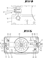
- the cleaning device 1 has the in FIG. 2 shown combination of a swing plate 3, a support plate 4 and a cleaning element 5 on.
- the oscillating plate 3 has on its upper side shown centrally on a rotational axis recording 22 for a drive axle of the engine.
- the drive shaft is used in combination with an eccentric on the one hand for fixing the oscillating plate 3 to the cleaning device 1, and on the other hand for causing oscillating oscillatory movements of the vibrating plate 3.
- the eccentric drive of the vibrating plate 3 is further to the publication EP 2 578 131 A1 directed.
- the vibrating plate 3 is preferably driven at an oscillation frequency of, for example, 1000 rpm up to 2000 rpm.
- This oscillatory movement of the oscillating plate 3 relative to a housing of the cleaning device 1 is superimposed during a wiping operation with a displacement of the wet cleaning device 2 over the surface to be cleaned by a user.
- Both movements that is to say both the manual displacement movement and the oscillatory movement of the oscillating plate 3, take place in the same plane, namely the plane of oscillation of the oscillating plate 3.
- the cleaning element 5 is a partially elastic trained cleaning cloth, in particular a microfiber cloth. This can be fastened with the aid of cleaning element fastenings 21, here Velcro fasteners, on corresponding cleaning element fastenings (not shown) of the support plate 4.
- the attachment means 6 of the swing plate 3 is a relative to the swing plate 3 displaceable latching element 11 having a free end portion 27.
- the latching element 11 is within a Guide device 14 guided and acted upon by the restoring force of a spring element 10.
- the guide device 14 is here designed according to the type of a guide slot, within which the latching element 11 is held linearly displaceable.
- the carrier plate 4 has, corresponding to the attachment means 6 of the oscillating plate 3, a receiving element 13 having an insertion bevel 28 and an undercut 12.
- the attachment means 6, 7 of the swing plate 3 and the support plate 4 are so far formed corresponding to each other, as the locking element 11 of the swing plate 3 slides in connection with the support plate 4 on the insertion bevel 28 of the receiving element 13 and finally the contour of the receiving element 13 following behind the Undercut 12 engages.
- the restoring force of the spring element 10 acts against the receiving element 13.
- the locking element 11 performs a linear movement within the guide device 14. When the latching connection is opened, the latching element 11 tends to move in the direction of a plate center, ie away from the receiving element 13.
- the latching element 11 When closing the locking element 11 moves after overcoming the insertion bevel 28 in the opposite direction of movement within the guide device 14, namely to the outside.
- the latching element 11 it would also be possible for the latching element 11 to run on an arcuate path of a guide slot.
- at least one locking element 11 has a permanent bias.
- the other, still latched locking element 11 has a remaining bias, which leads to the automatic separation of carrier plate 4 and vibrating plate 3.
- the locking elements 11 perform opposite movements. When you open the locking connection, the locking elements 11 move toward each other, while these move away from each other when closing the locking connection, so in each case in opposite directions of movement.
- the oscillating plate 3 and the carrier plate 4 also have corresponding centering means 23, 24 and centering receivers 25 (see FIG. 3 ) on.
- the centering means 23, 24 are formed on the support plate 4 projections, which can engage in the centering 25 of the vibrating plate 3.
- one of the centering receivers 25 is designed such that there is a range of motion in at least one direction of movement for the centering means 23, 24 located therein.
- FIG. 3 shows a bottom of the swing plate 3.
- the illustrated side of the swing plate 3 is the one that faces the support plate 4 in the connected state of support plate 4 and swing plate 3.
- One of the centering receptacles 25 in this case has an inner contour which has the same diameter as an outer contour of the centering means 23, 24, so that the centering means 23, 24 can be held without play within this centering receptacle 25.
- the second centering receptacle 25 has, relative to a spatial direction, a greater length than the diameter of the centering means 23, 24, so that in principle there is a range of motion for the centering means 23, 24 accommodated within this centering receptacle 25. By this range of motion tilting during joining or detachment of the swing plate 3 and support plate 4 is prevented.
- the centering means 23, 24 of the support plate 4 and the centering 25 of the vibrating plate 3 are arranged point-symmetrical relative to the rotation axis recording 22, so that the support plate 4 can be fixed with two different orientations on the vibrating plate 3, namely with two 180 ° about the axis of rotation 22 rotated Orientations.
- the vibration plate 3 is shown without arranged thereon carrier plate 4.
- the spring element 10 here is a torsion spring, which is fastened with one leg to the housing of the oscillating plate 3 and with the other leg to the latching element 11.
- FIG. 4 shows an enlarged portion of the vibrating plate 3 with latching element 11 arranged thereon.
- FIG. 5 shows a section through the swing plate 3 in a state connected to the support plate 4 state.
- the centering means 23, 24 of the support plate 4 are inserted into the centering 25 of the vibrating plate 3.
- the locking elements 11 are snapped together for securing the swing plate 3 and the support plate 4 behind the corresponding undercuts 12 of the receiving elements 13, wherein the spring elements 10 in the latched position of the locking elements 11 have a bias.
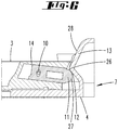
- FIG. 6 shows one of the locking elements 11 and one of the receiving elements 13 in a longitudinal section according to the in FIG. 5 shown line VI.
- the locking element 11 is completely locked behind the undercut 12 of the receiving element 13.
- the locking element 11 slips with its free end portion during the displacement of the oscillating plate 3 relative to the support plate 4 on the latching cam of the receiving element 13 along.
- the latching element 11 is displaced in the region of a vertex 26 of the latching curve maximum in the guide device 14, wherein this displacement takes place counter to the restoring force of the spring element 10.
- the latching element 11 is displaced out of the guide device 14 due to the restoring force of the spring element 10, namely behind that of the receiving element 13 provided undercut 12.
- the spring element 10 retains a bias.
- connection of the carrier plate 4 with the cleaning device 1, namely the oscillating plate 3, now works so that a user deposits the carrier plate 4 on a surface to be cleaned and the cleaning device 1 with the oscillating plate 3 leads over until the centering means 23, 24 of the carrier plate 4 can engage in the centering 25 of the vibrating plate 3.
- the support plate 4 is adjusted relative to the vibrating plate 3, so that subsequently a latching can take place.
- the user pushes the cleaning device 1 with the aid of the weight of the cleaning device 1 on the support plate 4 until the corresponding fastening means 6, 7 of the support plate 4 and the swing plate 3 engage.
- the latching then takes place in detail as explained above with displacement of the latching element 11 against the restoring force of the spring element 10 until the latching element 11 engages in the receiving element 13 of the support plate 4.
- the user tilts the cleaning device 1 into a position tilted relative to the surface to be cleaned, a so-called sack truck position.
- the support plate 4 is lifted with the cleaning element 5 disposed thereon of the surface to be cleaned and the actuating portion 15 is located above a wheel of the cleaning device 1.
- an actuator within the housing of the cleaning device. 1 to pivot, whereby the actuator presses against the support plate 4 and displaced relative to the swing plate 3.
- the bias of the spring element 10 supports a loosening of the corresponding fastener pair 8, 9, so that the oscillating plate 3 can then be removed from the support plate 4 also in the region of the corresponding other fastener pair 8, 9.
Abstract
Die Erfindung betrifft eine Reinigungseinrichtung (1), insbesondere für ein Feuchtreinigungsgerät (2), mit einer motorisch angetriebenen Schwingplatte (3) und einer mit der Schwingplatte (3) verbindbaren Trägerplatte (4) zur Aufnahme eines Reinigungselementes (5), wobei die Schwingplatte (3) und die Trägerplatte (4), bezogen auf einen miteinander verbundenen Zustand, an einander zugewandten Plattenseiten korrespondierende Befestigungsmittel (6, 7) aufweisen, wobei ein Befestigungsmittel (6, 7) der Schwingplatte (3) und ein Befestigungsmittel (6, 7) der Trägerplatte (4) ein Befestigungsmittelpaar (8, 9) bilden und wobei das Befestigungsmittelpaar (8, 9) einerseits ein entgegen einer Rückstellkraft eines Federelementes (10) verlagerbares Rastelement (11), und andererseits ein einen Hinterschnitt (12) aufweisendes Aufnahmeelement (13) zur Aufnahme des Rastelementes (11) aufweist. Um eine komfortable Befestigung von Schwingplatte (3) und Trägerplatte (4) zu erreichen, wird vorgeschlagen, dass in einer Draufsicht auf die zugewandten Plattenseiten auf einer Plattenseite ein Endbereich (27) des Rastelementes (11) und auf der anderen Plattenseite eine Einführschräge (28) des das Rastelement (11) zu dem Befestigungsmittelpaar (8, 9) ergänzenden Aufnahmeelementes (13) freiliegt und dass in einem aneinander befestigten Zustand der Schwingplatte (3) und der Trägerplatte (4) in einem Vertikalschnitt senkrecht zu einer Schwingebene der Schwingplatte (3) das Aufnahmeelement (13) das Rastelement (11) außenseitig umgreift.The invention relates to a cleaning device (1), in particular for a wet cleaning device (2), having a motor-driven oscillating plate (3) and a carrier plate (4) connectable to the oscillating plate (3) for receiving a cleaning element (5), wherein the oscillating plate ( 3) and the carrier plate (4), based on an interconnected state, on corresponding plate side corresponding fastening means (6, 7), wherein a fastening means (6, 7) of the oscillating plate (3) and a fastening means (6, 7) the support plate (4) form a pair of fasteners (8, 9) and wherein the fastener pair (8, 9) on the one hand a displaceable against a restoring force of a spring element (10) displaceable latching element (11), and on the other hand an undercut (12) exhibiting receiving element (13 ) for receiving the latching element (11). In order to achieve a comfortable attachment of oscillating plate (3) and carrier plate (4), it is proposed that in one plan view of the facing plate sides on one side of the plate an end portion (27) of the locking element (11) and on the other side of the plate an insertion bevel (28 ) of the latching element (11) to the fastener pair (8, 9) complementary receiving element (13) is exposed and that in a mutually fixed state of the swing plate (3) and the support plate (4) in a vertical section perpendicular to a swing plane of the swing plate (3 ), the receiving element (13) engages around the latching element (11) on the outside.
Description
Die Erfindung betrifft eine Reinigungseinrichtung, insbesondere für ein Feuchtreinigungsgerät, mit einer motorisch angetriebenen Schwingplatte und einer mit der Schwingplatte verbindbaren Trägerplatte zur Aufnahme eines Reinigungselementes, wobei die Schwingplatte und die Trägerplatte, bezogen auf einen miteinander verbundenen Zustand, an einander zugewandten Plattenseiten korrespondierende Befestigungsmittel aufweisen, wobei ein Befestigungsmittel der Schwingplatte und ein Befestigungsmittel der Trägerplatte ein Befestigungsmittelpaar bilden und wobei darüber hinaus das Befestigungsmittelpaar einerseits ein entgegen einer Rückstellkraft eines Federelementes verlagerbares Rastelement, und andererseits ein einen Hinterschnitt aufweisendes Aufnahmeelement zur Aufnahme des Rastelementes aufweist.The invention relates to a cleaning device, in particular for a wet cleaning device, with a motor-driven swing plate and connectable to the swing plate support plate for receiving a cleaning element, wherein the swing plate and the support plate, based on an interconnected state, on facing plate sides corresponding fasteners, wherein a fastening means of the oscillating plate and a fastening means of the support plate form a pair of fasteners and wherein, moreover, the fastener pair on the one hand against a restoring force of a spring element displaceable latching element, and on the other hand has an undercut exhibiting receiving element for receiving the latching element.
Zudem betrifft die Erfindung ein Feuchtreinigungsgerät mit einer solchen Reinigungseinrichtung.In addition, the invention relates to a wet cleaning device with such a cleaning device.
Reinigungseinrichtungen und Feuchtreinigungsgeräte der vorgenannten Art sind im Stand der Technik bekannt.Cleaning devices and wet cleaning devices of the aforementioned type are known in the art.
Die Reinigungseinrichtungen dienen insbesondere der Reinigung von Hartbodenbelägen, beispielsweise Fliesenböden oder Parkettböden, insbesondere im Haushaltsbereich. Die Reinigungseinrichtungen können beispielsweise als Vorsatzgeräte zur lösbaren Verbindung mit einem Basisgerät ausgebildet sein. Das Basisgerät stellt insbesondere eine Einrichtung zum Schieben der Reinigungseinrichtung über eine zu reinigende Fläche, eine Elektroversorgung, gegebenenfalls zusätzlich ein Sauggebläse, und weiteres zur Verfügung. Die Reinigungseinrichtungen weisen ein auf eine zu reinigende Fläche einwirkendes Reinigungselement auf, beispielsweise in Form eines textilen Reinigungstuches. Das Reinigungselement wird mittels einer Schwingplatte schwingend bewegt, wobei eine durch einen Nutzer der Reinigungseinrichtung während eines üblichen Reinigungsbetriebs durchgeführte Schiebeverlagerung (Vor- und Zurückverlagerung) von der Bewegung der Schwingplatte und damit auch der Bewegung des Reinigungselementes überlagert wird. Das Reinigungselement ist auf einer Trägerplatte befestigt, welche wiederum so an der Schwingplatte angeordnet werden kann, dass die Trägerplatte fest mit der Schwingplatte verbunden ist und die Schwingbewegung mitvollzieht. Die Schwingplatte wird beispielsweise durch einen elektromotorischen Exzenterantrieb rotiert.The cleaning devices are used in particular for the cleaning of hard floor coverings, such as tile floors or parquet floors, especially in the household sector. The cleaning devices can be designed, for example, as attachments for detachable connection to a base unit. The base unit in particular provides a device for pushing the cleaning device over a surface to be cleaned, an electrical supply, optionally in addition a suction fan, and further available. The cleaning devices have a cleaning element acting on a surface to be cleaned, for example in the form of a textile cleaning cloth. The cleaning element is oscillated by means of a vibrating plate, whereby a sliding displacement (forward and backward displacement) performed by a user of the cleaning device during a usual cleaning operation is superimposed by the movement of the vibrating plate and thus also the movement of the cleaning element. The cleaning element is mounted on a support plate, which in turn can be arranged on the swing plate so that the support plate is firmly connected to the swing plate and the swinging movement along. The vibrating plate is rotated for example by an electric motor eccentric drive.
Zunächst ist beispielsweise die Druckschrift
Des Weiteren sind auch Reinigungseinrichtungen bekannt, die ein Befestigungsmittelpaar mit einem Rastelement und einem Aufnahmeelement vorsehen. Die
Nachteilig bei den im Stand der Technik bekannten Reinigungseinrichtungen ist, dass der Nutzer die Trägerplatte zur Befestigung oder zum Trennen von der Schwingplatte mit seiner Hand ergreifen muss. Dabei kommt es zu einem Kontakt mit Reinigungsflüssigkeit, Schmutzflüssigkeit und/oder Schmutz.A disadvantage of the known in the prior art cleaning facilities that the user must take the carrier plate for attachment or disconnection of the vibrating plate with his hand. This leads to contact with cleaning fluid, dirt and / or dirt.
Ausgehend von dem vorgenannten Stand der Technik ist es daher Aufgabe der Erfindung, eine Reinigungseinrichtung zu schaffen, bei welcher die Trägerplatte an der Schwingplatte befestigt bzw. von dieser entfernt werden kann, ohne dass der Nutzer manuell an der Trägerplatte und/oder der Schwingplatte angreifen muss.Based on the aforementioned prior art, it is therefore an object of the invention to provide a cleaning device in which the support plate attached to the swing plate or can be removed from this, without the user must manually attack the support plate and / or the swing plate ,
Zur Lösung der vorgenannten Aufgabe schlägt die Erfindung vor, dass in einer Draufsicht auf die zugewandten Plattenseiten auf einer Plattenseite ein Endbereich des Rastelementes und auf der anderen Plattenseite eine Einführschräge des das Rastelement zu dem Befestigungsmittelpaar ergänzenden Aufnahmeelementes freiliegt und dass in einem aneinander befestigten Zustand der Schwingplatte und der Trägerplatte in einem Vertikalschnitt senkrecht zu einer Schwingebene der Schwingplatte das Aufnahmeelement das Rastelement außenseitig umgreift.To solve the above object, the invention proposes that in a plan view of the facing plate sides on a plate side, an end portion of the locking element and on the other side of the plate insertion of the locking element to the fastener pair complementary receiving element exposed and that in a mutually attached state of the vibrating plate and the support plate in a vertical section perpendicular to a swing plane of the swing plate, the receiving element surrounds the latching element on the outside.
Durch die Erfindung ist es zum Anbringen der Trägerplatte an der Schwingplatte nun nicht mehr erforderlich, dass ein Nutzer die Trägerplatte mit seiner Hand ergreift und auf die Schwingplatte aufschiebt. Vielmehr ist es nun möglich, die Trägerplatte mittels der verfederten Rastelemente mit der Schwingplatte zu verbinden, wobei die Rückstellkraft der Rastelemente durch eine Kraft überwunden wird, die der Nutzer beispielsweise durch Andrücken der Schwingplatte auf die auf der zu reinigenden Fläche befindliche Trägerplatte ausübt. Dabei platziert der Nutzer die Reinigungseinrichtung vorteilhaft so über der Trägerplatte, dass die Schwingplatte über der zu verbindenden Trägerplatte ruht und beide bezogen auf deren Längserstreckungen parallel zueinander ausgerichtet sind. Gegebenenfalls können zusätzlich Anordnungsmittel vorgegeben sein, welche eine relative Justage der Schwingplatte und der Trägerplatte zueinander vereinfachen. Der Nutzer führt die Befestigungsmittel der Schwingplatte über die Befestigungsmittel der Trägerplatte und drückt diese zusammen, bis das Rastelement hinter dem Hinterschnitt des Aufnahmeelementes einschnappt. Dadurch wird zur Verlagerung des Rastelementes zunächst die Rückstellkraft des Federelementes überwunden, und anschließend - wenn das Rastelement hinter dem Hinterschnitt eingerastet ist - das Rastelement in Richtung der Rückstellkraft zumindest teilweise wieder zurückverlagert, so dass das Rastelement fest hinter den Hinterschnitt greift und somit eine optimale, insbesondere spielfreie, Verbindung der Schwingplatte und der Trägerplatte aneinander bewirkt. In diesem spielfrei verbundenen Zustand vollzieht die Trägerplatte die gleiche Bewegung wie die Schwingplatte, das heißt während eines Reinigungsbetriebs beispielsweise die typische Schwingbewegung über die zu reinigende Fläche. Erfindungsgemäß liegt in einer Draufsicht auf die zugewandten Plattenseiten einerseits ein Endbereich des Rastelementes, und andererseits eine Einführschräge des Aufnahmeelementes, welches das Rastelement aufnimmt, frei. Wenn das Rastelement in das Aufnahmeelement eingerastet ist, nämlich in einem aneinander befestigten Zustand der Schwingplatte und der Trägerplatte, umgreift das Aufnahmeelement - betrachtet in einem Schnitt orthogonal zu der Schwingebene der Schwingplatte - das Rastelement außenseitig, d. h., dass das Rastelement ausgehend von einer Plattenmitte von innen in das Aufnahmeelement eingreift. Bei bspw. einer Ausführung, in welcher das Rastelement an der Schwingplatte angeordnet ist und das Aufnahmeelement an der Trägerplatte, ist die Schwingplatte im verbundenen Zustand innen und das Aufnahmeelement der Trägerplatte außen angeordnet. Zusammen mit der Einführschräge ergibt sich dadurch eine günstige, vom Nutzer durchzuführende Druck-Rastverbindung der beiderseitigen Befestigungselemente von Schwingplatte und Trägerplatte, da das von oben zu bewegende Teil, nämlich die Schwingplatte, in das unten liegende Teil, nämlich die Trägerplatte, einfach eingesetzt werden kann.By means of the invention, it is no longer necessary for the carrier plate to be attached to the oscillating plate so that a user grips the carrier plate with his hand and pushes it onto the oscillating plate. Rather, it is now possible to connect the support plate by means of the spring-loaded locking elements with the swinging plate, wherein the restoring force of the locking elements is overcome by a force exerted by the user, for example, by pressing the swing plate on the carrier plate located on the surface to be cleaned. In this case, the user advantageously places the cleaning device over the carrier plate such that the oscillating plate rests above the carrier plate to be connected and both are aligned parallel to one another with respect to their longitudinal extent. Optionally, additional arrangement means can be predetermined, which simplify a relative adjustment of the vibrating plate and the support plate to each other. The user guides the fastening means of the oscillating plate over the fastening means of the support plate and presses them together until the latching element snaps behind the undercut of the receiving element. As a result, the restoring force of the spring element is first overcome for the displacement of the locking element, and then - if the locking element is engaged behind the undercut - the locking element at least partially shifted back in the direction of the restoring force, so that the locking element firmly engages behind the undercut and thus optimal, particular backlash, compound of the vibrating plate and the support plate causes each other. In this play-free connected state, the support plate performs the same movement as the vibrating plate, that is, during a cleaning operation, for example, the typical swinging motion over the surface to be cleaned. According to the invention is in a plan view of the facing plate sides on the one hand an end portion of the locking element, and on the other hand, an insertion of the receiving element, which receives the locking element, free. When the latching element is engaged in the receiving element, namely in a mutually attached state of the swing plate and the support plate, the receiving element - viewed in a section orthogonal to the swing plane of the swing plate - surrounds the latching element on the outside, ie, that the latching element, starting from a center of engages inside the receiving element. For example, a version in which the detent element is arranged on the oscillating plate and the receiving element on the carrier plate, the oscillating plate is arranged in the connected state inside and the receiving element of the carrier plate on the outside. Together with the insertion, this results in a cheap, to be carried out by the user pressure-locking connection of the mutually fastening elements of vibrating plate and carrier plate, since the moving from the top part, namely the vibrating plate, in the underlying part, namely the support plate, can be easily used ,
Es kann vorgesehen sein, dass die Reinigungseinrichtung nur ein einziges Befestigungsmittelpaar aufweist. In diesem Fall ist die Trägerplatte nur an einem bestimmten Verbindungspunkt von Trägerplatte und Schwingplatte durch ein federkraftbeaufschlagtes Rastelement von der Schwingplatte lösbar bzw. an dieser verrastbar. Sofern, wie bevorzugt vorgeschlagen wird, die Reinigungseinrichtung mehrere Befestigungsmittelpaare aufweist, ist eine federunterstützte Verrastung bzw. Entriegelung der Trägerplatte an mehreren Seiten der Reinigungseinrichtung möglich. Vorzugsweise liegen die Befestigungsmittelpaare sich dabei bezogen auf eine Umfangsrichtung der Trägerplatte bzw. der Schwingplatte gegenüber. Ein jedes der Befestigungsmittelpaare weist mindestens ein verfedertes Rastelement auf, welches zum Fügen und Lösen der Trägerplatte relativ zu der Schwingplatte dient. Die Füge- und Lösekraft des Rastelementes kann über die Rückstellkraft des Federelementes und die Rastkurve des Hinterschnittes eingestellt werden. Insgesamt ergibt sich eine robuste, preiswerte und toleranzunempfindliche Verbindung von Schwingplatte und Trägerplatte, welche ein häufiges Lösen und Wiederverbinden ermöglicht.It can be provided that the cleaning device has only a single pair of fasteners. In this case, the carrier plate is detachable or latchable to the vibrating plate only at a certain connection point between the carrier plate and the vibrating plate by a spring-loaded latching element. If, as is preferred, the cleaning device has a plurality of fastener pairs, a spring-assisted latching or unlocking of the support plate on several sides of the cleaning device is possible. Preferably, the fastener pairs are in relation to a circumferential direction of the support plate or the vibrating plate opposite. Each of the fastener pairs has at least one spring-loaded latching element, which serves for joining and releasing the support plate relative to the vibration plate. The joining and releasing force of the locking element can be adjusted via the restoring force of the spring element and the latching curve of the undercut. Overall, results in a robust, inexpensive and tolerances insensitive connection of vibrating plate and carrier plate, which allows frequent loosening and reconnecting.
Es wird vorgeschlagen, dass das dem Rastelement zugeordnete Federelement eine Torsionsfeder ist. Die Torsionsfeder, auch Schenkelfeder genannt, greift mit einem Endbereich an einer Basis der Schwingplatte bzw. der Trägerplatte an, und mit einem gegenüberliegenden Endbereich an dem Rastelement der Schwingplatte bzw. Trägerplatte. Die Rückstellkraft des Federelementes ist in Richtung der Raststellung des Rastelementes gerichtet. Alternativ kann das Federelement auch eine Blattfeder, Schraubenfeder, Schneckenfeder oder dergleichen sein.It is proposed that the spring element associated with the detent element is a torsion spring. The torsion spring, also called leg spring, engages with an end portion on a base of the swing plate or the support plate on, and with an opposite end region on the latching element of the vibrating plate or carrier plate. The restoring force of the spring element is directed in the direction of the locking position of the locking element. Alternatively, the spring element may also be a leaf spring, coil spring, worm spring or the like.
Insbesondere wird vorgeschlagen, dass das Rastelement und das Federelement einteilig ausgebildet sind. Insbesondere können das Rastelement und das Federelement als federelastisches Rastelement ausgebildet sein. Gemäß dieser Ausgestaltung kann das Rastelement beispielsweise eine Blattfeder sein, welche endseitig als Rastmittel ausgeformt ist. Das Rastelement kann aus einem federelastischen Material gebildet sein und einen angeformten Rasthaken, eine Rastnase oder dergleichen aufweisen. Durch diese Ausgestaltung ist die Anzahl der verwendeten Bauteile für die Rastmechanik besonders gering.In particular, it is proposed that the latching element and the spring element are integrally formed. In particular, the latching element and the spring element may be formed as a resilient latching element. According to this embodiment, the locking element may be, for example, a leaf spring, which is formed at the end as a locking means. The locking element may be formed of a resilient material and having a molded latching hook, a latching nose or the like. With this configuration, the number of components used for the latching mechanism is particularly low.
Des Weiteren kann vorgesehen sein, dass ein freier Endbereich des Rastelementes ein rotierbar gelagertes Rotationselement aufweist, welches bei Verbinden des Rastelementes und des Aufnahmeelementes rotiert. Das Rotationselement kann beispielsweise ein an einem Endbereich des Rastelementes angeordnetes Rollenelement sein, welches während einer Verrastung auf dem Aufnahmeelement abrollt. Dadurch wird die Reibung zwischen dem Rastelement und dem Aufnahmeelement minimiert, da das Rastelement nicht mehr an dem Aufnahmeelement entlang schleift, um hinter den Hinterschnitt zu gelangen. Diese Ausführung ist darüber hinaus besonders verschleißarm. Das Rotationselement ist beispielsweise an einer Rotationsachse des Rastelementes gelagert, welche Rotationsachse vorzugsweise senkrecht zu der Rastrichtung steht.Furthermore, it can be provided that a free end region of the latching element has a rotatably mounted rotational element which rotates upon connection of the latching element and the receiving element. The rotation element can be, for example, a roller element arranged on an end region of the latching element, which rolls on the receiving element during latching. As a result, the friction between the locking element and the receiving element is minimized because the locking element no longer grinds along the receiving element to get behind the undercut. This design is also particularly wear-resistant. The rotation element is mounted for example on a rotational axis of the latching element, which rotation axis is preferably perpendicular to the latching direction.
Gemäß einer möglichen Ausführung wird vorgeschlagen, dass die Schwingplatte und die Trägerplatte mindestens zwei Befestigungsmittelpaare aufweisen, wobei zwei Befestigungsmittelpaare bezogen auf eine Längserstreckung der Schwingplatte bzw. Trägerplatte an gegenüberliegenden Endbereichen der Schwingplatte bzw. Trägerplatte angeordnet sind. Die beiden Befestigungsmittelpaare befinden sich vorzugsweise in derselben, zu einer Schwingungsebene der Schwingplatte bzw. der Trägerplatte parallelen Ebene. Die Befestigungsmittelpaare liegen bezogen auf die Längserstreckung der Schwingplatte bzw. Trägerplatte möglichst weit auseinander, so dass sich bei einem Lösen eines der Befestigungsmittelpaare durch einseitiges Verlagern der Trägerplatte gegen die Schwingplatte ein möglichst großer Hebel ergibt. Besonders bevorzugt hat beim Entrasten eines Rastelementes eines ersten Befestigungsmittelpaares ein noch verrastetes Rastmittel eines entsprechend zweiten Befestigungsmittelpaares aufgrund einer Rückstellkraft eines zugeordneten Federelementes eine noch verbleibende Vorspannung, so dass die Trägerplatte und die Schwingplatte automatisch getrennt werden.According to a possible embodiment it is proposed that the oscillating plate and the carrier plate at least two pairs of fasteners have, wherein two pairs of fasteners are arranged with respect to a longitudinal extent of the vibrating plate or support plate at opposite end portions of the vibrating plate or support plate. The two pairs of fasteners are preferably located in the same plane parallel to a plane of vibration of the oscillating plate or the carrier plate. The pairs of fasteners are based on the longitudinal extent of the vibrating plate or support plate as far apart as possible, so that results in a release of one of the fastener pairs by unilateral displacement of the support plate against the vibrating plate as large a lever. Particularly preferably, when unlocking a locking element of a first pair of fasteners a still latched locking means of a corresponding second fastener pair due to a restoring force of an associated spring element has a remaining bias, so that the support plate and the vibrating plate are automatically separated.
Des Weiteren wird vorgeschlagen, dass das Rastelement entlang und relativ zu einer linearen oder bogenförmigen Führungseinrichtung der Schwingplatte oder Trägerplatte verlagerbar ist. Das Rastelement läuft während einer Verlagerungsbewegung entlang der Führungseinrichtung, wodurch - je nach der Form der Führungseinrichtung - eine entweder lineare oder bogenförmige Verlagerungsbahn durchlaufen wird. Besonders vorzugsweise kann die Führungseinrichtung beispielsweise eine Führungskulisse sein, innerhalb welcher zumindest ein Teilbereich des Rastelementes läuft. Diese Führungseinrichtung ist gerade oder gekrümmt ausgebildet und gibt die Bewegungsrichtung des Rastelementes vor. Diese Bewegungsrichtung beeinflusst die Füge- bzw. Lösekraft, welche zum Fügen bzw. Trennen des Befestigungsmittelpaares erforderlich ist. Dies ist zum einen bedingt durch die Verlagerungsrichtung des Rastelementes relativ zur Richtung der Gravitation, und zum anderen durch eine Reibfläche zwischen dem Rastelement und dem korrespondierenden Aufnahmeelement. Des Weiteren kann die Verlagerungsbahn der Führungseinrichtung auch durch die Art des Federelementes bestimmt sein, insbesondere durch die Wirkrichtung des Federelementes.Furthermore, it is proposed that the latching element along and relative to a linear or arcuate guide means of the swing plate or support plate is displaced. The locking element runs during a displacement movement along the guide means, whereby - depending on the shape of the guide means - a traversed either linear or arcuate displacement track. Particularly preferably, the guide means may for example be a guide slot within which runs at least a portion of the locking element. This guide device is straight or curved and defines the direction of movement of the locking element. This direction of movement influences the joining or releasing force, which is required for joining or separating the pair of fasteners. This is partly due to the displacement direction of the locking element relative to the direction of gravity, and on the other hand by a friction surface between the locking element and the corresponding receiving element. Furthermore, the displacement path of the guide device can also be influenced by the type of Be determined spring element, in particular by the direction of action of the spring element.
Zudem kann vorgesehen sein, dass das Federelement bei mit dem Aufnahmeelement verrastetem Zustand des Rastelementes zumindest teilweise gespannt ist. Durch diese Ausgestaltung weist das Federelement im verrasteten Zustand des Rastelementes eine Vorspannung auf, welche beim Lösen der Trägerplatte von der Schwingplatte ein Auswerfen der Trägerplatte unterstützt. Dadurch ist das Lösen der Trägerplatte besonders einfach und insbesondere ohne manuelles Ergreifen der Trägerplatte bzw. der Schwingplatte durch den Nutzer möglich. Beim Entrasten eines Rastelementes eines ersten Befestigungsmittelpaares weist ein noch verrastetes Rastelement eines zweiten Befestigungsmittelpaares eine verbleibende Vorspannung des Federelementes auf, welche zum automatischen Auswerfen der Trägerplatte führt. Sofern die Reinigungseinrichtung ein verfedertes Befestigungsmittelpaar und ein starres Befestigungsmittelpaar aufweist, erfolgt das Verschwenken der Trägerplatte bzw. Schwingplatte um ein Schwenkzentrum des starren Befestigungsmittelpaares, so dass die Vorspannung des Federelementes des anderen Befestigungsmittelpaares zu einem unterstützten Auslösen des verfederten Rastelementes aus dem korrespondierenden Aufnahmeelement führt.In addition, it can be provided that the spring element is at least partially tensioned when latched with the receiving element state of the locking element. By this configuration, the spring element in the latched state of the locking element to a bias, which supports the ejection of the carrier plate upon release of the carrier plate of the vibrating plate. Thus, the release of the support plate is particularly simple and in particular without manual gripping of the support plate or the swing plate by the user possible. When unlocking a locking element of a first pair of fasteners, a still latched locking element of a second fastener pair has a remaining bias of the spring element, which leads to the automatic ejection of the support plate. If the cleaning device has a spring-loaded pair of fasteners and a rigid pair of fasteners, the pivoting of the support plate or swing plate about a pivot center of the rigid fastener pair, so that the bias of the spring element of the other fastener pair leads to a supported release of the spring-loaded locking element from the corresponding receiving element.
Des Weiteren wird vorgeschlagen, dass das Rastelement an der Schwingplatte angeordnet ist, und dass das Aufnahmeelement an der Trägerplatte angeordnet ist. Gemäß dieser Ausgestaltung befindet sich das bewegliche Rastelement an der Schwingplatte, welche üblicherweise an der Reinigungseinrichtung verbleibt. Die Trägerplatte, welche zur Aufnahme des Reinigungselementes ausgebildet ist, ist hingegen besonders einfach und ohne bewegliche Elemente ausgestaltet. Grundsätzlich ist es jedoch auch möglich, dass das Rastelement an der Trägerplatte angeordnet ist, und dass das Aufnahmeelement an der Schwingplatte ausgebildet ist.Furthermore, it is proposed that the latching element is arranged on the oscillating plate, and that the receiving element is arranged on the carrier plate. According to this embodiment, the movable locking element is located on the vibrating plate, which usually remains on the cleaning device. The support plate, which is designed to accommodate the cleaning element, however, is particularly simple and designed without moving elements. In principle, however, it is also possible that the locking element is arranged on the support plate, and that the receiving element is formed on the oscillating plate.
Schließlich wird vorgeschlagen, dass einem Befestigungsmittelpaar ein Betätigungselement zugeordnet ist, welches infolge einer Betätigung gegen die Trägerplatte verlagerbar ist, um diese von der Schwingplatte zu lösen. Das Betätigungselement kann beispielsweise ein um eine Achse schwenkbewegliches Betätigungselement sein, welches von dem Nutzer durch einen Tritt auf einen Betätigungsbereich auf der Gehäuseoberseite der Reinigungseinrichtung verschwenkt werden kann. Die Betätigung ist vorzugsweise nur in einer Sackkarrenstellung der Reinigungseinrichtung, das heißt in einer relativ zu einer zu reinigenden Fläche verschwenkten Stellung der Reinigungseinrichtung, und damit auch der Schwingplatte und der Trägerplatte, möglich. Das Lösen der Trägerplatte von der Schwingplatte ist nur bei ausgeschalteter Reinigungseinrichtung, das heißt bei ausgeschaltetem Motor, in der Sackkarrenstellung möglich. Die Sackkarrenstellung entspricht einer Transportstellung bei welcher die Reinigungseinrichtung auf an einer Gerätehinterkante angeordnete Rollen gekippt ist. In dieser Stellung ist die Trägerplatte mit einem gegebenenfalls daran angeordneten Reinigungselement ausreichend von der zu reinigenden Fläche abgehoben, um die Trägerplatte von der Schwingplatte lösen zu können. Die Trennung der Befestigungsmittel eines Befestigungsmittelpaares erfolgt dann durch eine Kraft, welche gegen die Trägerplatte wirkt, vorzugsweise gegen eine Randkante der Trägerplatte. Das Betätigungselement ist dabei zur Einleitung der Kraft gegen ein Gehäuse der Reinigungseinrichtung gestützt, nämlich vorzugsweise gegen den vorgenannten Betätigungsbereich. Das Betätigungselement ist vorzugsweise Teil einer Wippenmechanik, welche bei Betätigung des Betätigungsbereiches und damit Verschwenken des Betätigungselementes gegen die Trägerplatte wirkt. Alternativ sind selbstverständlich auch elektrische oder andere mechanisch betätigte Aktoren möglich.Finally, it is proposed that a fastening element pair is associated with an actuating element, which is displaceable as a result of actuation against the carrier plate in order to release it from the oscillating plate. The actuating element can, for example, be an actuating element which can be pivoted about an axis and which can be swiveled by the user through a step onto an actuating region on the upper side of the housing of the cleaning device. The operation is preferably only in a sacking position of the cleaning device, that is in a relative to a surface to be cleaned pivoted position of the cleaning device, and thus also the vibrating plate and the carrier plate, possible. The release of the support plate of the swing plate is possible only when the cleaning device, that is with the engine off, in the sack truck position. The Sackkarrenstellung corresponds to a transport position in which the cleaning device is tilted on arranged on a device trailing edge rollers. In this position, the support plate with a possibly arranged thereon cleaning element is sufficiently lifted from the surface to be cleaned in order to solve the support plate of the vibrating plate can. The separation of the fastening means of a pair of fasteners is then carried out by a force which acts against the support plate, preferably against a peripheral edge of the support plate. The actuating element is supported for introducing the force against a housing of the cleaning device, namely preferably against the aforementioned operating range. The actuating element is preferably part of a rocker mechanism, which acts on actuation of the actuating region and thus pivoting of the actuating element against the carrier plate. Alternatively, of course, electrical or other mechanically actuated actuators are possible.
Neben der zuvor beschriebenen Reinigungseinrichtung wird mit der Erfindung des Weiteren auch ein Feuchtreinigungsgerät mit einer solchen Reinigungseinrichtung vorgeschlagen. Das Feuchtreinigungsgerät kann grundsätzlich jedes Reinigungsgerät sein, welches ausschließlich oder unter anderem eine Feuchtreinigung durchführen kann. Hierzu zählen zum einen handgeführte Feuchtreinigungsgeräte, jedoch auch selbsttätig verfahrbare Feuchtreinigungsgeräte, wie insbesondere Reinigungsroboter. Daneben sind auch kombinierte Trocken - und Feucht-Reinigungsgeräte umfasst. Darüber hinaus sind neben üblichen Bodenreinigungsgeräten zur Reinigung eines Fußbodens beispielsweise auch Feuchtreinigungsgeräte zur Reinigung von Überbodenflächen umfasst, beispielsweise zur Reinigung von Fensterscheiben, Regalböden, Fußleisten, Stufen und dergleichen.In addition to the cleaning device described above, the invention also proposes a wet cleaning device having such a cleaning device. The wet cleaning device can basically be any cleaning device that can perform a wet cleaning exclusively or among other things. These include, on the one hand hand-held wet cleaning equipment, but also automatically movable wet cleaning equipment, in particular cleaning robot. In addition, combined dry and wet cleaning devices are included. In addition, in addition to conventional floor cleaning equipment for cleaning a floor, for example, also wet cleaning equipment for cleaning overground surfaces includes, for example, for cleaning windows, shelves, baseboards, steps and the like.
Zudem gelten alle in Bezug auf die Reinigungseinrichtung genannten Merkmale analog auch in Bezug auf das vorgeschlagene Feuchtreinigungsgerät.In addition, all mentioned in relation to the cleaning device features apply analogously also in relation to the proposed wet cleaning device.
Im Folgenden wird die Erfindung anhand von Ausführungsbeispielen näher erläutert. Es zeigen:
- Fig. 1
- ein Feuchtreinigungsgerät mit einer Reinigungseinrichtung,
- Fig. 2
- eine Explosionsdarstellung mit einer Schwingplatte, einer Trägerplatte und einem Reinigungselement,
- Fig. 3
- eine Unteransicht der Schwingplatte,
- Fig. 4
- einen vergrößerten Teilbereich der Schwingplatte,
- Fig. 5
- eine Schnittansicht der Schwingplatte mit daran angeordneter Trägerplatte und
- Fig. 6
- einen Längsschnitt gemäß der Linie VI in
Fig. 5 .
- Fig. 1
- a wet cleaning device with a cleaning device,
- Fig. 2
- an exploded view with a swing plate, a support plate and a cleaning element,
- Fig. 3
- a bottom view of the vibrating plate,
- Fig. 4
- an enlarged portion of the vibrating plate,
- Fig. 5
- a sectional view of the vibrating plate arranged thereon carrier plate and
- Fig. 6
- a longitudinal section along the line VI in
Fig. 5 ,
Die Reinigungseinrichtung 1 weist die in
Die Schwingplatte 3 wird bevorzugt mit einer Oszillationsfrequenz von beispielsweise 1000 U/min bis hin zu 2000 U/min angetrieben. Diese Schwingbewegung der Schwingplatte 3 relativ zu einem Gehäuse der Reinigungseinrichtung 1 überlagert sich während eines Wischbetriebs mit einer Verlagerung des Feuchtreinigungsgerätes 2 über die zu reinigende Fläche durch einen Nutzer. Beide Bewegungen, das heißt sowohl die manuelle Verlagerungsbewegung als auch die Schwingbewegung der Schwingplatte 3, erfolgen in derselben Ebene, nämlich der Schwingungsebene der Schwingplatte 3.The vibrating
Das Reinigungselement 5 ist ein teilweise elastisch ausgebildetes Reinigungstuch, insbesondere ein Mikrofasertuch. Dieses kann mit Hilfe von Reinigungselementbefestigungen 21, hier Klettverschlüssen, an entsprechenden Reinigungselementbefestigungen (nicht dargestellt) der Trägerplatte 4 befestigt werden.The
Zur Befestigung der Trägerplatte 4 an der Schwingplatte 3 weisen diese korrespondierende Befestigungsmittel 6, 7 auf, wobei jeweils ein Befestigungsmittel 6 der Schwingplatte 3 und ein Befestigungsmittel 7 der Trägerplatte 4 zu einem Befestigungsmittelpaar 8, 9 verbindbar sind. Das Befestigungsmittel 6 der Schwingplatte 3 ist ein relativ zu der Schwingplatte 3 verlagerbares Rastelement 11 mit einem freien Endbereich 27. Das Rastelement 11 ist innerhalb einer Führungseinrichtung 14 geführt und mit der Rückstellkraft eines Federelementes 10 beaufschlagt. Die Führungseinrichtung 14 ist hier nach der Art einer Führungskulisse ausgebildet, innerhalb welcher das Rastelement 11 linear verschieblich gehalten ist. Die Trägerplatte 4 weist korrespondierend zu dem Befestigungsmittel 6 der Schwingplatte 3 ein eine Einführschräge 28 und einen Hinterschnitt 12 aufweisendes Aufnahmeelement 13 auf. Die Befestigungsmittel 6, 7 der Schwingplatte 3 und der Trägerplatte 4 sind insofern korrespondierend zueinander ausgebildet, als das Rastelement 11 der Schwingplatte 3 bei Verbindung mit der Trägerplatte 4 an der Einführschräge 28 des Aufnahmeelements 13 entlang gleitet und schließlich der Kontur des Aufnahmeelementes 13 folgend hinter dem Hinterschnitt 12 einrastet. Dabei wirkt die Rückstellkraft des Federelementes 10 gegen das Aufnahmeelement 13. Das Rastelement 11 führt eine Linearbewegung innerhalb der Führungseinrichtung 14 aus. Beim Öffnen der Rastverbindung wandert das Rastelement 11 tendenziell in Richtung einer Plattenmitte, d. h. von dem Aufnahmeelement 13 weg. Beim Schließen bewegt sich das Rastelement 11 nach Überwinden der Einführschräge 28 in entgegengesetzte Bewegungsrichtung innerhalb der Führungseinrichtung 14, nämlich nach außen. Alternativ wäre es auch möglich, dass das Rastelement 11 auf einer bogenförmigen Bahn einer Führungskulisse läuft. Bei einer Verbindung mit zwei solchen Befestigungsmittelpaaren 8, 9 weist mindestens ein Rastelement 11 eine permanente Vorspannung auf. Beim Entrasten des Rastelementes 11 aus dem korrespondierenden Aufnahmeelement 13 hat das andere, noch verrastete Rastelement 11 eine verbleibende Vorspannung, welche zum automatischen Trennen von Trägerplatte 4 und Schwingplatte 3 führt. Die Rastelemente 11 führen einander entgegengesetzte Bewegungen aus. Beim Öffnen der Rastverbindung bewegen sich die Rastelemente 11 aufeinander zu, während sich diese beim Schließen der Rastverbindung voneinander weg bewegen, also jeweils in entgegengesetzte Bewegungsrichtungen.For fastening the
Die Schwingplatte 3 und die Trägerplatte 4 weisen zum Zwecke der korrekten Positionierung der Trägerplatte 4 an der Schwingplatte 3 des Weiteren korrespondierende Zentriermittel 23, 24 und Zentrieraufnahmen 25 (siehe
Das Verbinden der Trägerplatte 4 mit der Reinigungseinrichtung 1, nämlich der Schwingplatte 3, funktioniert nun so, dass ein Nutzer die Trägerplatte 4 auf einer zu reinigenden Fläche ablegt und die Reinigungseinrichtung 1 mit der Schwingplatte 3 darüber führt, bis die Zentriermittel 23, 24 der Trägerplatte 4 in die Zentrieraufnahmen 25 der Schwingplatte 3 eingreifen können. Damit ist die Trägerplatte 4 relativ zu der Schwingplatte 3 justiert, so dass anschließend eine Verrastung erfolgen kann. Im Weiteren drückt der Nutzer die Reinigungseinrichtung 1 unter Zuhilfenahme der Gewichtskraft der Reinigungseinrichtung 1 auf die Trägerplatte 4, bis die korrespondierenden Befestigungsmittel 6, 7 der Trägerplatte 4 und der Schwingplatte 3 einrasten. Die Verrastung erfolgt dann im Einzelnen wie zuvor erläutert unter Verlagerung des Rastelementes 11 entgegen der Rückstellkraft des Federelementes 10, bis das Rastelement 11 in das Aufnahmeelement 13 der Trägerplatte 4 einrastet.The connection of the
Um die Trägerplatte 4 nun ausgehend von dem verrasteten Zustand von der Schwingplatte 3 lösen zu können, kippt der Nutzer die Reinigungseinrichtung 1 in eine relativ zu der zu reinigenden Fläche verkippte Stellung, eine sogenannte Sackkarrenstellung. Dabei ist die Trägerplatte 4 mit dem daran angeordneten Reinigungselement 5 von der zu reinigenden Fläche abgehoben und der Betätigungsbereich 15 befindet sich über einem Rad der Reinigungseinrichtung 1. Dadurch ist es möglich, mittels eines Tritts auf den Betätigungsbereich 15 ein Betätigungselement innerhalb des Gehäuses der Reinigungseinrichtung 1 zu verschwenken, wodurch das Betätigungselement gegen die Trägerplatte 4 drückt und diese relativ zu der Schwingplatte 3 verlagert. Durch die Verlagerung der Trägerplatte 4 wird eines der Befestigungsmittelpaare 8, 9 gelöst, indem das entsprechende Rastmittel 11 aus dem Aufnahmeelement 13 herausgeschwenkt wird. Dabei unterstützt die Vorspannung des Federelementes 10 ein Lösen des entsprechenden Befestigungsmittelpaares 8, 9, so dass die Schwingplatte 3 anschließend auch im Bereich des entsprechend anderen Befestigungsmittelpaares 8, 9 von der Trägerplatte 4 entfernt werden kann.
Claims (9)
Applications Claiming Priority (1)
| Application Number | Priority Date | Filing Date | Title |
|---|---|---|---|
| DE102017116673.4A DE102017116673A1 (en) | 2017-07-24 | 2017-07-24 | Cleaning device with a motor driven vibration plate |
Publications (2)
| Publication Number | Publication Date |
|---|---|
| EP3449794A1 true EP3449794A1 (en) | 2019-03-06 |
| EP3449794B1 EP3449794B1 (en) | 2020-06-17 |
Family
ID=63014363
Family Applications (1)
| Application Number | Title | Priority Date | Filing Date |
|---|---|---|---|
| EP18184640.3A Active EP3449794B1 (en) | 2017-07-24 | 2018-07-20 | Cleaning device with a motor-driven oscillating plate |
Country Status (6)
| Country | Link |
|---|---|
| EP (1) | EP3449794B1 (en) |
| JP (1) | JP2019048038A (en) |
| CN (1) | CN109288460B (en) |
| DE (1) | DE102017116673A1 (en) |
| ES (1) | ES2818974T3 (en) |
| TW (1) | TW201907849A (en) |
Families Citing this family (1)
| Publication number | Priority date | Publication date | Assignee | Title |
|---|---|---|---|---|
| JP2021186739A (en) * | 2020-05-29 | 2021-12-13 | Asti株式会社 | Wiping clean tool and wiping clean method |
Citations (4)
| Publication number | Priority date | Publication date | Assignee | Title |
|---|---|---|---|---|
| US1693919A (en) * | 1924-02-12 | 1928-12-04 | Floorola Corp | Brush holder for floor polishers |
| DE102010000378A1 (en) * | 2010-02-11 | 2011-08-11 | Vorwerk & Co. Interholding GmbH, 42275 | Floor wiper, particularly attachment device for electric motor-driven household vacuum cleaner for wet cleaning of hard floor covering, such as tile floor or parquet floor, has driven oscillating body for fastening wiping cloth |
| DE102011050181A1 (en) * | 2010-05-25 | 2011-12-01 | Vorwerk & Co. Interholding Gmbh | Floor wiping device i.e. motor-driven floor wiping device, for use as attachment of hand-guided electrical operated household vacuum cleaner to clean e.g. tiled floor, has section whose spring deflection takes place at end region of guide |
| EP2578131A1 (en) * | 2011-10-04 | 2013-04-10 | Vorwerk & Co. Interholding GmbH | Floor mopping device and powered body that pivots relative to a fixed section |
Family Cites Families (5)
| Publication number | Priority date | Publication date | Assignee | Title |
|---|---|---|---|---|
| CN2318968Y (en) * | 1998-03-11 | 1999-05-19 | 吴孝景 | Multipurpose mop |
| US9295365B2 (en) * | 2007-02-21 | 2016-03-29 | Bissell Homecare, Inc. | Extractor with auxiliary fluid dispenser |
| KR100831619B1 (en) * | 2007-04-12 | 2008-05-26 | 주식회사 마미로봇 | Floor-cloth fixing structure |
| KR101253245B1 (en) * | 2010-09-06 | 2013-04-16 | 한경희 | steam cleaner |
| CN203354473U (en) * | 2013-06-19 | 2013-12-25 | 业展电器(深圳)有限公司 | Automatic floor cleaner |
-
2017
- 2017-07-24 DE DE102017116673.4A patent/DE102017116673A1/en not_active Withdrawn
-
2018
- 2018-07-19 JP JP2018135565A patent/JP2019048038A/en active Pending
- 2018-07-20 ES ES18184640T patent/ES2818974T3/en active Active
- 2018-07-20 EP EP18184640.3A patent/EP3449794B1/en active Active
- 2018-07-23 TW TW107125361A patent/TW201907849A/en unknown
- 2018-07-24 CN CN201810819045.XA patent/CN109288460B/en active Active
Patent Citations (4)
| Publication number | Priority date | Publication date | Assignee | Title |
|---|---|---|---|---|
| US1693919A (en) * | 1924-02-12 | 1928-12-04 | Floorola Corp | Brush holder for floor polishers |
| DE102010000378A1 (en) * | 2010-02-11 | 2011-08-11 | Vorwerk & Co. Interholding GmbH, 42275 | Floor wiper, particularly attachment device for electric motor-driven household vacuum cleaner for wet cleaning of hard floor covering, such as tile floor or parquet floor, has driven oscillating body for fastening wiping cloth |
| DE102011050181A1 (en) * | 2010-05-25 | 2011-12-01 | Vorwerk & Co. Interholding Gmbh | Floor wiping device i.e. motor-driven floor wiping device, for use as attachment of hand-guided electrical operated household vacuum cleaner to clean e.g. tiled floor, has section whose spring deflection takes place at end region of guide |
| EP2578131A1 (en) * | 2011-10-04 | 2013-04-10 | Vorwerk & Co. Interholding GmbH | Floor mopping device and powered body that pivots relative to a fixed section |
Also Published As
| Publication number | Publication date |
|---|---|
| TW201907849A (en) | 2019-03-01 |
| DE102017116673A1 (en) | 2019-02-14 |
| CN109288460B (en) | 2021-06-22 |
| CN109288460A (en) | 2019-02-01 |
| ES2818974T3 (en) | 2021-04-14 |
| JP2019048038A (en) | 2019-03-28 |
| EP3449794B1 (en) | 2020-06-17 |
Similar Documents
| Publication | Publication Date | Title |
|---|---|---|
| EP2934268B1 (en) | Cleaning brush for a ground surface celaning device and ground surface cleaning device with a cleaning brush | |
| EP2578131B1 (en) | Floor mopping device and powered body that pivots relative to a fixed section | |
| EP1899116B1 (en) | Mobile floor cleaning appliance | |
| DE202012012850U1 (en) | Exfollationshandgerät | |
| DE3403246A1 (en) | ELECTRICALLY ADJUSTABLE VEHICLE SEAT | |
| DE4100333A1 (en) | MECHANISM FOR HEIGHT ADJUSTMENT OF FLOOR CLEANING DEVICES | |
| DE202006007395U1 (en) | Lever operated suction element, comprising lever with specifically shaped rear area for locking unit when not in use | |
| EP3722545A1 (en) | Vehicle door handle arrangement | |
| EP1882125B1 (en) | Positioning foot unit of a domestic appliance | |
| EP2926690A1 (en) | Mechanism for an office chair | |
| DE102010038026A1 (en) | Vacuum cleaner nozzle with magnetic lock | |
| DE102004061855A1 (en) | Suction brush for a vacuum cleaner | |
| EP3449794B1 (en) | Cleaning device with a motor-driven oscillating plate | |
| EP3449793B1 (en) | Cleaning device with a motor-driven vibratory plate | |
| DE102017118379A1 (en) | Cleaning device with a motor driven vibration plate | |
| WO2006061045A1 (en) | Floor cleaning device | |
| DE1655409B2 (en) | DOUBLE WIPER ARM | |
| DE2146316A1 (en) | Vacuum cleaner tool with two working handles | |
| DE3415637A1 (en) | FLOOR SWEEPER WITH IMPROVED DRIVE WHEEL DESIGN | |
| EP3192422B1 (en) | Floor cleaning machine | |
| EP3185742B1 (en) | Suction nozzle and hard surface vacuum cleaner | |
| DE102018003607B3 (en) | Hinge means | |
| EP2018821A2 (en) | Cleaning device for a floor cleaning machine and floor cleaning machine with such a cleaning device | |
| EP0993265A1 (en) | Cleaner | |
| EP3185743B1 (en) | Vacuum nozzle and vacuum cleaner for hard surfaces |
Legal Events
| Date | Code | Title | Description |
|---|---|---|---|
| PUAI | Public reference made under article 153(3) epc to a published international application that has entered the european phase |
Free format text: ORIGINAL CODE: 0009012 |
|
| STAA | Information on the status of an ep patent application or granted ep patent |
Free format text: STATUS: THE APPLICATION HAS BEEN PUBLISHED |
|
| AK | Designated contracting states |
Kind code of ref document: A1 Designated state(s): AL AT BE BG CH CY CZ DE DK EE ES FI FR GB GR HR HU IE IS IT LI LT LU LV MC MK MT NL NO PL PT RO RS SE SI SK SM TR |
|
| AX | Request for extension of the european patent |
Extension state: BA ME |
|
| STAA | Information on the status of an ep patent application or granted ep patent |
Free format text: STATUS: REQUEST FOR EXAMINATION WAS MADE |
|
| 17P | Request for examination filed |
Effective date: 20190904 |
|
| RBV | Designated contracting states (corrected) |
Designated state(s): AL AT BE BG CH CY CZ DE DK EE ES FI FR GB GR HR HU IE IS IT LI LT LU LV MC MK MT NL NO PL PT RO RS SE SI SK SM TR |
|
| RIC1 | Information provided on ipc code assigned before grant |
Ipc: A47L 11/12 20060101ALI20191113BHEP Ipc: A47L 11/06 20060101AFI20191113BHEP Ipc: A47L 11/40 20060101ALI20191113BHEP |
|
| GRAP | Despatch of communication of intention to grant a patent |
Free format text: ORIGINAL CODE: EPIDOSNIGR1 |
|
| STAA | Information on the status of an ep patent application or granted ep patent |
Free format text: STATUS: GRANT OF PATENT IS INTENDED |
|
| INTG | Intention to grant announced |
Effective date: 20200107 |
|
| GRAS | Grant fee paid |
Free format text: ORIGINAL CODE: EPIDOSNIGR3 |
|
| GRAA | (expected) grant |
Free format text: ORIGINAL CODE: 0009210 |
|
| STAA | Information on the status of an ep patent application or granted ep patent |
Free format text: STATUS: THE PATENT HAS BEEN GRANTED |
|
| AK | Designated contracting states |
Kind code of ref document: B1 Designated state(s): AL AT BE BG CH CY CZ DE DK EE ES FI FR GB GR HR HU IE IS IT LI LT LU LV MC MK MT NL NO PL PT RO RS SE SI SK SM TR |
|
| REG | Reference to a national code |
Ref country code: GB Ref legal event code: FG4D Free format text: NOT ENGLISH |
|
| REG | Reference to a national code |
Ref country code: CH Ref legal event code: EP |
|
| REG | Reference to a national code |
Ref country code: IE Ref legal event code: FG4D Free format text: LANGUAGE OF EP DOCUMENT: GERMAN |
|
| REG | Reference to a national code |
Ref country code: DE Ref legal event code: R096 Ref document number: 502018001675 Country of ref document: DE |
|
| REG | Reference to a national code |
Ref country code: AT Ref legal event code: REF Ref document number: 1280331 Country of ref document: AT Kind code of ref document: T Effective date: 20200715 |
|
| PG25 | Lapsed in a contracting state [announced via postgrant information from national office to epo] |
Ref country code: FI Free format text: LAPSE BECAUSE OF FAILURE TO SUBMIT A TRANSLATION OF THE DESCRIPTION OR TO PAY THE FEE WITHIN THE PRESCRIBED TIME-LIMIT Effective date: 20200617 Ref country code: NO Free format text: LAPSE BECAUSE OF FAILURE TO SUBMIT A TRANSLATION OF THE DESCRIPTION OR TO PAY THE FEE WITHIN THE PRESCRIBED TIME-LIMIT Effective date: 20200917 Ref country code: GR Free format text: LAPSE BECAUSE OF FAILURE TO SUBMIT A TRANSLATION OF THE DESCRIPTION OR TO PAY THE FEE WITHIN THE PRESCRIBED TIME-LIMIT Effective date: 20200918 Ref country code: SE Free format text: LAPSE BECAUSE OF FAILURE TO SUBMIT A TRANSLATION OF THE DESCRIPTION OR TO PAY THE FEE WITHIN THE PRESCRIBED TIME-LIMIT Effective date: 20200617 Ref country code: LT Free format text: LAPSE BECAUSE OF FAILURE TO SUBMIT A TRANSLATION OF THE DESCRIPTION OR TO PAY THE FEE WITHIN THE PRESCRIBED TIME-LIMIT Effective date: 20200617 |
|
| PGFP | Annual fee paid to national office [announced via postgrant information from national office to epo] |
Ref country code: CZ Payment date: 20200813 Year of fee payment: 3 |
|
| REG | Reference to a national code |
Ref country code: LT Ref legal event code: MG4D |
|
| REG | Reference to a national code |
Ref country code: NL Ref legal event code: MP Effective date: 20200617 |
|
| PG25 | Lapsed in a contracting state [announced via postgrant information from national office to epo] |
Ref country code: HR Free format text: LAPSE BECAUSE OF FAILURE TO SUBMIT A TRANSLATION OF THE DESCRIPTION OR TO PAY THE FEE WITHIN THE PRESCRIBED TIME-LIMIT Effective date: 20200617 Ref country code: BG Free format text: LAPSE BECAUSE OF FAILURE TO SUBMIT A TRANSLATION OF THE DESCRIPTION OR TO PAY THE FEE WITHIN THE PRESCRIBED TIME-LIMIT Effective date: 20200917 Ref country code: RS Free format text: LAPSE BECAUSE OF FAILURE TO SUBMIT A TRANSLATION OF THE DESCRIPTION OR TO PAY THE FEE WITHIN THE PRESCRIBED TIME-LIMIT Effective date: 20200617 Ref country code: LV Free format text: LAPSE BECAUSE OF FAILURE TO SUBMIT A TRANSLATION OF THE DESCRIPTION OR TO PAY THE FEE WITHIN THE PRESCRIBED TIME-LIMIT Effective date: 20200617 |
|
| PG25 | Lapsed in a contracting state [announced via postgrant information from national office to epo] |
Ref country code: NL Free format text: LAPSE BECAUSE OF FAILURE TO SUBMIT A TRANSLATION OF THE DESCRIPTION OR TO PAY THE FEE WITHIN THE PRESCRIBED TIME-LIMIT Effective date: 20200617 Ref country code: AL Free format text: LAPSE BECAUSE OF FAILURE TO SUBMIT A TRANSLATION OF THE DESCRIPTION OR TO PAY THE FEE WITHIN THE PRESCRIBED TIME-LIMIT Effective date: 20200617 |
|
| PG25 | Lapsed in a contracting state [announced via postgrant information from national office to epo] |
Ref country code: EE Free format text: LAPSE BECAUSE OF FAILURE TO SUBMIT A TRANSLATION OF THE DESCRIPTION OR TO PAY THE FEE WITHIN THE PRESCRIBED TIME-LIMIT Effective date: 20200617 Ref country code: SM Free format text: LAPSE BECAUSE OF FAILURE TO SUBMIT A TRANSLATION OF THE DESCRIPTION OR TO PAY THE FEE WITHIN THE PRESCRIBED TIME-LIMIT Effective date: 20200617 Ref country code: RO Free format text: LAPSE BECAUSE OF FAILURE TO SUBMIT A TRANSLATION OF THE DESCRIPTION OR TO PAY THE FEE WITHIN THE PRESCRIBED TIME-LIMIT Effective date: 20200617 Ref country code: PT Free format text: LAPSE BECAUSE OF FAILURE TO SUBMIT A TRANSLATION OF THE DESCRIPTION OR TO PAY THE FEE WITHIN THE PRESCRIBED TIME-LIMIT Effective date: 20201019 |
|
| PG25 | Lapsed in a contracting state [announced via postgrant information from national office to epo] |
Ref country code: PL Free format text: LAPSE BECAUSE OF FAILURE TO SUBMIT A TRANSLATION OF THE DESCRIPTION OR TO PAY THE FEE WITHIN THE PRESCRIBED TIME-LIMIT Effective date: 20200617 Ref country code: SK Free format text: LAPSE BECAUSE OF FAILURE TO SUBMIT A TRANSLATION OF THE DESCRIPTION OR TO PAY THE FEE WITHIN THE PRESCRIBED TIME-LIMIT Effective date: 20200617 Ref country code: IS Free format text: LAPSE BECAUSE OF FAILURE TO SUBMIT A TRANSLATION OF THE DESCRIPTION OR TO PAY THE FEE WITHIN THE PRESCRIBED TIME-LIMIT Effective date: 20201017 |
|
| REG | Reference to a national code |
Ref country code: DE Ref legal event code: R097 Ref document number: 502018001675 Country of ref document: DE |
|
| PG25 | Lapsed in a contracting state [announced via postgrant information from national office to epo] |
Ref country code: MC Free format text: LAPSE BECAUSE OF FAILURE TO SUBMIT A TRANSLATION OF THE DESCRIPTION OR TO PAY THE FEE WITHIN THE PRESCRIBED TIME-LIMIT Effective date: 20200617 |
|
| REG | Reference to a national code |
Ref country code: ES Ref legal event code: FG2A Ref document number: 2818974 Country of ref document: ES Kind code of ref document: T3 Effective date: 20210414 |
|
| PLBE | No opposition filed within time limit |
Free format text: ORIGINAL CODE: 0009261 |
|
| STAA | Information on the status of an ep patent application or granted ep patent |
Free format text: STATUS: NO OPPOSITION FILED WITHIN TIME LIMIT |
|
| REG | Reference to a national code |
Ref country code: BE Ref legal event code: MM Effective date: 20200731 |
|
| PG25 | Lapsed in a contracting state [announced via postgrant information from national office to epo] |
Ref country code: DK Free format text: LAPSE BECAUSE OF FAILURE TO SUBMIT A TRANSLATION OF THE DESCRIPTION OR TO PAY THE FEE WITHIN THE PRESCRIBED TIME-LIMIT Effective date: 20200617 Ref country code: LU Free format text: LAPSE BECAUSE OF NON-PAYMENT OF DUE FEES Effective date: 20200720 |
|
| 26N | No opposition filed |
Effective date: 20210318 |
|
| PG25 | Lapsed in a contracting state [announced via postgrant information from national office to epo] |
Ref country code: SI Free format text: LAPSE BECAUSE OF FAILURE TO SUBMIT A TRANSLATION OF THE DESCRIPTION OR TO PAY THE FEE WITHIN THE PRESCRIBED TIME-LIMIT Effective date: 20200617 Ref country code: BE Free format text: LAPSE BECAUSE OF NON-PAYMENT OF DUE FEES Effective date: 20200731 |
|
| PG25 | Lapsed in a contracting state [announced via postgrant information from national office to epo] |
Ref country code: IE Free format text: LAPSE BECAUSE OF NON-PAYMENT OF DUE FEES Effective date: 20200720 |
|
| REG | Reference to a national code |
Ref country code: CH Ref legal event code: PL |
|
| PG25 | Lapsed in a contracting state [announced via postgrant information from national office to epo] |
Ref country code: LI Free format text: LAPSE BECAUSE OF NON-PAYMENT OF DUE FEES Effective date: 20210731 Ref country code: CH Free format text: LAPSE BECAUSE OF NON-PAYMENT OF DUE FEES Effective date: 20210731 |
|
| PG25 | Lapsed in a contracting state [announced via postgrant information from national office to epo] |
Ref country code: TR Free format text: LAPSE BECAUSE OF FAILURE TO SUBMIT A TRANSLATION OF THE DESCRIPTION OR TO PAY THE FEE WITHIN THE PRESCRIBED TIME-LIMIT Effective date: 20200617 Ref country code: MT Free format text: LAPSE BECAUSE OF FAILURE TO SUBMIT A TRANSLATION OF THE DESCRIPTION OR TO PAY THE FEE WITHIN THE PRESCRIBED TIME-LIMIT Effective date: 20200617 Ref country code: CZ Free format text: LAPSE BECAUSE OF NON-PAYMENT OF DUE FEES Effective date: 20210720 Ref country code: CY Free format text: LAPSE BECAUSE OF FAILURE TO SUBMIT A TRANSLATION OF THE DESCRIPTION OR TO PAY THE FEE WITHIN THE PRESCRIBED TIME-LIMIT Effective date: 20200617 |
|
| PG25 | Lapsed in a contracting state [announced via postgrant information from national office to epo] |
Ref country code: MK Free format text: LAPSE BECAUSE OF FAILURE TO SUBMIT A TRANSLATION OF THE DESCRIPTION OR TO PAY THE FEE WITHIN THE PRESCRIBED TIME-LIMIT Effective date: 20200617 |
|
| GBPC | Gb: european patent ceased through non-payment of renewal fee |
Effective date: 20220720 |
|
| PG25 | Lapsed in a contracting state [announced via postgrant information from national office to epo] |
Ref country code: GB Free format text: LAPSE BECAUSE OF NON-PAYMENT OF DUE FEES Effective date: 20220720 |
|
| P01 | Opt-out of the competence of the unified patent court (upc) registered |
Effective date: 20230517 |
|
| PGFP | Annual fee paid to national office [announced via postgrant information from national office to epo] |
Ref country code: IT Payment date: 20230731 Year of fee payment: 6 Ref country code: ES Payment date: 20230821 Year of fee payment: 6 |
|
| PGFP | Annual fee paid to national office [announced via postgrant information from national office to epo] |
Ref country code: FR Payment date: 20230724 Year of fee payment: 6 Ref country code: DE Payment date: 20230720 Year of fee payment: 6 |