EP3449718A1 - Dispositif de pesage et appareil de récuperation de cueillette - Google Patents
Dispositif de pesage et appareil de récuperation de cueillette Download PDFInfo
- Publication number
- EP3449718A1 EP3449718A1 EP18191754.3A EP18191754A EP3449718A1 EP 3449718 A1 EP3449718 A1 EP 3449718A1 EP 18191754 A EP18191754 A EP 18191754A EP 3449718 A1 EP3449718 A1 EP 3449718A1
- Authority
- EP
- European Patent Office
- Prior art keywords
- roller
- weighing
- bale
- press
- support flange
- Prior art date
- Legal status (The legal status is an assumption and is not a legal conclusion. Google has not performed a legal analysis and makes no representation as to the accuracy of the status listed.)
- Granted
Links
- 238000005303 weighing Methods 0.000 title claims abstract description 65
- 238000003306 harvesting Methods 0.000 title claims abstract description 27
- 239000000463 material Substances 0.000 claims description 8
- 238000003860 storage Methods 0.000 claims description 4
- 239000011257 shell material Substances 0.000 abstract 1
- 238000013461 design Methods 0.000 description 4
- 230000007613 environmental effect Effects 0.000 description 3
- 239000000758 substrate Substances 0.000 description 3
- 230000009286 beneficial effect Effects 0.000 description 2
- 230000015572 biosynthetic process Effects 0.000 description 2
- 239000004744 fabric Substances 0.000 description 2
- 230000002349 favourable effect Effects 0.000 description 2
- 238000012549 training Methods 0.000 description 2
- 229920000742 Cotton Polymers 0.000 description 1
- 230000005355 Hall effect Effects 0.000 description 1
- 241000208125 Nicotiana Species 0.000 description 1
- 235000002637 Nicotiana tabacum Nutrition 0.000 description 1
- 238000005352 clarification Methods 0.000 description 1
- 230000003750 conditioning effect Effects 0.000 description 1
- 230000001419 dependent effect Effects 0.000 description 1
- 238000001514 detection method Methods 0.000 description 1
- 238000011161 development Methods 0.000 description 1
- 230000018109 developmental process Effects 0.000 description 1
- 239000000428 dust Substances 0.000 description 1
- 230000004907 flux Effects 0.000 description 1
- 239000011888 foil Substances 0.000 description 1
- 239000007769 metal material Substances 0.000 description 1
- 238000012986 modification Methods 0.000 description 1
- 230000004048 modification Effects 0.000 description 1
- 239000000123 paper Substances 0.000 description 1
- 230000035515 penetration Effects 0.000 description 1
- 238000004321 preservation Methods 0.000 description 1
- 230000001681 protective effect Effects 0.000 description 1
- 230000001105 regulatory effect Effects 0.000 description 1
- 230000000284 resting effect Effects 0.000 description 1
- 238000005096 rolling process Methods 0.000 description 1
- 238000007789 sealing Methods 0.000 description 1
- 238000007493 shaping process Methods 0.000 description 1
- 239000010902 straw Substances 0.000 description 1
- 238000012546 transfer Methods 0.000 description 1
- 239000002699 waste material Substances 0.000 description 1
- 238000004804 winding Methods 0.000 description 1
Images


Classifications
-
- G—PHYSICS
- G01—MEASURING; TESTING
- G01G—WEIGHING
- G01G7/00—Weighing apparatus wherein the balancing is effected by magnetic, electromagnetic, or electrostatic action, or by means not provided for in the preceding groups
- G01G7/02—Weighing apparatus wherein the balancing is effected by magnetic, electromagnetic, or electrostatic action, or by means not provided for in the preceding groups by electromagnetic action
-
- A—HUMAN NECESSITIES
- A01—AGRICULTURE; FORESTRY; ANIMAL HUSBANDRY; HUNTING; TRAPPING; FISHING
- A01F—PROCESSING OF HARVESTED PRODUCE; HAY OR STRAW PRESSES; DEVICES FOR STORING AGRICULTURAL OR HORTICULTURAL PRODUCE
- A01F15/00—Baling presses for straw, hay or the like
- A01F15/08—Details
- A01F15/0825—Regulating or controlling density or shape of the bale
- A01F15/0833—Regulating or controlling density or shape of the bale for round balers
-
- A—HUMAN NECESSITIES
- A01—AGRICULTURE; FORESTRY; ANIMAL HUSBANDRY; HUNTING; TRAPPING; FISHING
- A01F—PROCESSING OF HARVESTED PRODUCE; HAY OR STRAW PRESSES; DEVICES FOR STORING AGRICULTURAL OR HORTICULTURAL PRODUCE
- A01F15/00—Baling presses for straw, hay or the like
- A01F15/02—Baling presses for straw, hay or the like with press-boxes
-
- A—HUMAN NECESSITIES
- A01—AGRICULTURE; FORESTRY; ANIMAL HUSBANDRY; HUNTING; TRAPPING; FISHING
- A01F—PROCESSING OF HARVESTED PRODUCE; HAY OR STRAW PRESSES; DEVICES FOR STORING AGRICULTURAL OR HORTICULTURAL PRODUCE
- A01F15/00—Baling presses for straw, hay or the like
- A01F15/07—Rotobalers, i.e. machines for forming cylindrical bales by winding and pressing
-
- G—PHYSICS
- G01—MEASURING; TESTING
- G01G—WEIGHING
- G01G19/00—Weighing apparatus or methods adapted for special purposes not provided for in the preceding groups
- G01G19/52—Weighing apparatus combined with other objects, e.g. furniture
-
- G—PHYSICS
- G01—MEASURING; TESTING
- G01G—WEIGHING
- G01G7/00—Weighing apparatus wherein the balancing is effected by magnetic, electromagnetic, or electrostatic action, or by means not provided for in the preceding groups
-
- G—PHYSICS
- G01—MEASURING; TESTING
- G01L—MEASURING FORCE, STRESS, TORQUE, WORK, MECHANICAL POWER, MECHANICAL EFFICIENCY, OR FLUID PRESSURE
- G01L1/00—Measuring force or stress, in general
- G01L1/12—Measuring force or stress, in general by measuring variations in the magnetic properties of materials resulting from the application of stress
-
- A—HUMAN NECESSITIES
- A01—AGRICULTURE; FORESTRY; ANIMAL HUSBANDRY; HUNTING; TRAPPING; FISHING
- A01F—PROCESSING OF HARVESTED PRODUCE; HAY OR STRAW PRESSES; DEVICES FOR STORING AGRICULTURAL OR HORTICULTURAL PRODUCE
- A01F15/00—Baling presses for straw, hay or the like
- A01F15/08—Details
- A01F15/0875—Discharge devices
- A01F2015/0891—Weighing the finished bale before falling to ground
Definitions
- the invention relates to a weighing device for detecting the weight of a pressing bale on a roll, comprising at least one weighing means and a harvesting device.
- weighting devices for detecting the weight of a press bale are known. Such weighing devices are complex, require additional components and / or are exposed to environmental influences or must be protected by protective devices against environmental influences. That's how it shows DE-A1-10241215 a round baler with a weighing device for detecting the weight of pressed round bales, which is adapted to detect the force exerted by a round bale on a located in the baling chamber of the round baler support element.
- the weighing device comprises a measuring cell arranged between the support element and a frame of the round baler.
- the object underlying the invention is seen to provide a weighing device and a Erntebergungs réelle, by which the aforementioned disadvantages are overcome.
- a weighing device for detecting the weight of a pressing bale on a roll has at least one weighing means. If the weighing means is integrated in a bearing device of the roller, this allows a compact design.
- the roller may be, for example, a support roller, a support roller and / or a drive roller, which may be provided for example, the pressed bales on a harvesting device, such as a baler, in particular a baler for producing round cylindrical bales or pressed bales, or one
- the pressed bale can be directly in contact with the roll or indirectly interact with it, for example by resting on one or more of the roll or two or more such rolls wrapped around the belt and / or chain (s).
- the Weighing device may
- the weighing means has a bearing pin and / or the weighing means is designed as a bearing pin, this contributes to a compact design.
- the detection of the weight of the press bale can be done in this way as directly as possible to a component which is exposed to the load by the weight.
- the weighing means or the bearing bolt preferably has at least one sensor, in particular a Hall sensor, on or it is designed as such. This too can reduce the number of components, support a compact design and / or direct weight-force determination.
- the weighing means has an axle or shaft and / or is designed as an axle or shaft, which preferably carries the roller or about which the roller is rotatably arranged.
- a Hall sensor uses the Hall effect to measure magnetic fields.
- the Hall sensor can have at least one magnet which moves as a function of a loading state of the weighing means or of the bearing pin.
- the magnetic flux density may change, which may result in an electrical signal, which may be transmitted to a control or regulating device, for example, to be evaluated there and / or control one or more function (s) of the harvesting device or to regulate.
- the weighing means is rotatably received at one end in a carrier flange which can be connected to a frame of a harvesting device, so that a secure connection of the weighing means to the frame can be produced, which contributes to a stable mounting of the roller.
- the weighing means may extend from the carrier flange into a hollow interior of the roller and preferably be received in the interior of the roller from a bearing supporting the roller. The weighing means is thus accommodated or stored inside the roller, whereby it or its storage by the roller or a hollow cylinder of the roller from environmental influences, such as moisture, dust or crop, is protected.
- a sleeve which is preferably rotatably received together with the weighing means of the support flange, and through which the weighing means may extend.
- An overload protection can help to protect the weighing means or the bearing pin from excessive loads, such as those that can be caused by particularly heavy pressed bales.
- Such an overload protection can be designed in particular such that it connects the roller in the event of overload at least temporarily and / or partially frictionally in particular with the support flange, so that no or only part of the load is absorbed by the weighing means or the bearing pin.
- a gap can be provided between the bearing pin and the sleeve, which in the case of an overload is reduced in such a way that the weighing means comes into frictional engagement with the sleeve in particular.
- This can be particularly favorable in applications in which a rotation of the roller should be at least substantially free even in the event of an overload, for example in a roll in or on a baling chamber of a baler.
- a gap may be provided between the roller and the support flange, which is reduced in the event of overload in such a way that the roller comes directly or indirectly in particular non-positively on the support flange for conditioning.
- Such a configuration may be beneficial if a rotation of the roller in case of overload can not be ensured, for example because this does not or only slightly restricts a function of the harvesting device.
- the roller is suitable for supporting a press bale, in particular in or on a harvesting device.
- Such a weighing device can be used on a harvesting device, in particular an agricultural or industrial baling press, preferably a press for forming round-cylindrical pressed bales or a wrapping device for wrapping a press bale with a wrapping material, for example in the form of a net or a foil, with at least one roller for supporting a bale , are used.
- a harvesting device may have one or more weighing device (s). It may be provided that the weighing device is provided in the baling chamber of a baling press or adjacent thereto. But it can also be provided that the Weighing device is designed to determine the weight of a press bale received on a wrapping device.
- the weighing device can be arranged for example on or adjacent to a receiving device or also to a transport device for transferring a pressing bale from a first position, for example to a baling chamber of a baling press, into a second position, for example on or in a wrapping device.
- a weighing device is provided both in or on the pressing space and in or on the wrapping device.
- a weighing device is provided either in or on the pressing space or in or on the wrapping device.
- the pressed bales can be, in particular, a bale of harvested material. But it is also conceivable that the pressed bales of waste, paper, fabric or fabric, cotton, tobacco, etc. composed.
- FIG. 1 a harvesting device 10 is shown in the manner of an agricultural baler for pressing a round cylindrical pressing bale 12 having a frame 14 which is supported by means of wheels 16 on a substrate 18 and by means of a drawbar 20 to a towing vehicle, not shown, for. B. an agricultural tractor, can be connected.
- a receiving device 22 for receiving and feeding of crop, which promotes cut crop via an inlet 24 into a baling chamber 26.
- the harvesting device 10 has a wrapping device 28 for wrapping a pressing bale 12 formed in the baling press with a wrapping material 30, for example a film.
- the wrapping device 28 comprises a frame 32, a wrapping table or a receiving device 34 for receiving the bale 16 to be wrapped, and winding arms 36 which can be set in motion for wrapping the bale 12 with the wrapping material 30 by means of a suitable drive (not shown), on.
- the receiving device 34 in turn has two rollers 38, one of which in the FIG. 2 is shown which supports the pressed bale 12 during transfer of the press bale 12 from the pressing space 26 in its wrapping position on the wrapping device 28 and / or during the wrapping of the bale 12 with wrapping material 30 or for this purpose with a to the rollers 38 and a belt 44 wound around a lateral surface 40 of the rollers 38 at least substantially defining hollow belt 44.
- the hollow cylinder 42 may be made in a known manner from a metallic material, for example in the manner of a sheet, or from another suitable material, for example a plastic.
- FIG. 2a Reference is made in the one in the FIG. 3 A designated left side region of one of the rollers 38 is shown enlarged. In the following, only this area is referred to, wherein a right-sided, in FIG. 2 also shown region according to the present embodiment is designed accordingly.
- the roller 38 is mounted in its left-side end region 46 via a bearing device 48 with a support flange 50 and a bearing pin 52 on the frame 32 of the wrapping device 28.
- the bearing device 48 furthermore has a weighing device 54a, as will be described in more detail below.
- a weighing device 54a is also provided in the right-hand side, as well as the second roller 38 is formed accordingly is. But it is quite conceivable that only one of the rollers 38 on the one hand or on both sides with a weighing device 54a cooperates.
- two respective substantially disc-shaped webs 58, 60 are fixedly connected to the hollow cylinder 42, wherein the web arranged in the end region 46 of the roller 38 and the hollow cylinder 42 is hereafter is referred to as a boundary web 58 and with respect to the boundary web 58 further in the interior 56 of the hollow cylinder 46 arranged web as a bearing web 60.
- the rotatably received in the support flange 50 bearing pin 52 extends from the support flange 50 in the interior 56 of the hollow cylinder 42.
- the support flange 50 in turn extends through the opening 62 in the boundary web 58 such that between the bearing pin 52 and the boundary web 58 at least a gap 66 is provided when no pressing bale 12 is received by the rollers 38.
- a support flange 50 opposite end portion 68 of the bearing pin 52 carries a bearing 70 in the manner of a rolling or ball bearing, which is received by the opening 64 in the bearing web 60 such that the hollow cylinder 42 and the roller 38 about the bearing pin 60th can rotate and the roller 38 is supported by the bearing 70 on the bearing pin 52.
- the bearing pin 60 is designed as a weighing means 70 suitable for determining a weight or load acting on the bearing pin 60 .
- the bearing pin 60 has a sensor 74 which is preferably designed in the manner of a known Hall sensor.
- a sensor 78 is provided, which transmits values recorded by the sensor 70 to a control device (ECU) which is shown only by way of an indication.
- the weight of a pressing bale 12 directly or indirectly supported on the rollers 40 is received over the hollow cylinders 42, bearing webs 60 and bearings 70 about which the rollers 38 rotate.
- the bearings 70 in turn transmit the forces acting on the bearing pin 60, where the sensor or sensors 74 determine the corresponding load.
- the limiting webs 58 are not in contact with the bearing pin 60. If an overload situation now occurs, for example because the pressed bale 12 to be supported exceeds a permissible weight force, which may occur, for example, in the case of very moist crop, the bearing bolt 60 deforms in such a way that he ultimately partially or completely comes to rest with the boundary web 58.
- the weight force is no longer completely borne by the bearing pin or bolts 60, but rather is at least partially transmitted to the flange 50 via the limiting web or webs 58. If the bearing pin 60 bears against the support flange 50, a rotation of the roller 38 is limited and optionally prevented.
- FIG. 3 there is shown a second embodiment of a harvesting apparatus 10, such as a press, for forming round cylindrical billets.
- a harvesting apparatus 10 such as a press
- the harvesting device 10 has a frame 14, which is supported by means of wheels 16 on a substrate 18 and is by means of a drawbar 20 to a towing vehicle, not shown, for. B. a tractor, connectable.
- the baling chamber 26 of the baling press 10 is designed to be invariable in size and the press 10 has a multiplicity of pressing rollers 80 running parallel to one another (by way of example only a few rollers 80 have been provided with the reference numeral 80) which are located on a circular arc during the formation of a pressing bale 12, and at least some of them are powered.
- the pressing rollers 80 are used in addition to a pressing and a shaping, in particular also a rotation generation or a rotational preservation of the arranged in the pressing space 26 pressing bale 12.
- a pivotable ejector flap 82 is provided for ejection a press bale 12 from the pressing chamber 26 can release an opening 84.
- the ejector flap 82 is shown in the drawing in a slightly open position.
- press rollers 80 On which the press bale 12 at least at least at the time of weight force determination at least approximately exclusively supported and in the following for clarification as a roller 86th is also associated with a weighing device 54b together.
- a roller 86 is shown in a representation as shown in FIG Fig. 2b shows, with corresponding components are named with the same reference characters as in the previous embodiment.
- the roller 86 has a hollow cylinder 42 with an internal, fixed to the hollow cylinder 42 connected Support web 60, which is rotatably supported on a bearing 70.
- a support flange 50 is provided which is connected to the frame 14 of the press and rotatably receives a bearing pin 52.
- At its opposite end flange 68 of the support flange 50 of the bearing pin 52 is rotatably received on the bearing 70 in the bearing web 60.
- a bearing pin 52 designed as a weighing means 72 is provided only in one area.
- a sleeve 88 is provided which receives and surrounds the bearing pin 52 and the one end is rotatably received together with the bearing pin 52 of the support flange 50. At the other end, the sleeve 88 extends to the bearing web 60 or the opening 64 in the bearing web 60. Between the bearing pin 52 and the sleeve 88, a gap 90 is at least then provided when no pressing bale 12 is received by the rollers 38.
- sealing means 92 are provided which prevent the penetration of foreign bodies and / or moisture into the interior 56 of the hollow cylinder 42, but at least substantially not support the roller 38 or the hollow cylinder 42.
- the weight of a press bale 12 supported on the rollers 38 is received over the hollow cylinder 42, the bearing webs 60 and the bearings 70 about which the roller 86 rotates.
- the bearings 70 in turn transmit the forces acting on the bearing pin 60, where the sensor 74 determines a corresponding deformation, respectively load of the bearing pin 60.
- the sleeve 88 is not in contact with the end portion 68 of the bearing pin 52. If an overload situation now occurs, for example because the pressed bale 12 to be supported exceeds a permissible dynamic range, then the bearing pin 52 deforms such that it or its end region 68 ultimately comes to rest with the sleeve 88.
- the weight force is no longer completely absorbed or supported by the bearing bolt 52, but at least partially transmitted to the support flange 50 via the sleeve 88.
- An at least substantially unimpeded rotation of the roller 78 is also possible here when the bearing pin 52 and the sleeve 88 are in abutment.
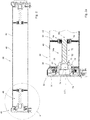
- FIG. 5 a third embodiment of a harvesting device 10 is shown, wherein as far as possible or appropriate reference signs used in the preceding figures are used.
- the harvesting device 10 also has here a frame 14, which is supported by means of wheels 16 on the ground 18. The shown
- Harvesting device 10 is designed in the manner of a round baler with a variable pressing space 26
- a drawbar 20 is provided to attach the harvesting device 10 to an agricultural tractor, not shown, and to be able to pull over a field.
- a receiving device 22 in the form of a pick-up serves to receive lying on the ground 16 crop, z. B. of stored in a swath hay or straw.
- the picked up by the receiving device 22 crop is fed via an inlet 24 a baling chamber 26 and rolled up there spirally to form a round cylindrical pressed bale 12, bound and then deposited on the substrate 16.
- the pressing space 26 is further formed by an endless pressing means or belt 99, which according to the present embodiment is designed in the manner of two juxtaposed pressing belts and by a number of stationary rollers 100, 102, 104, 106 and movable rollers 108, 110 , 112, 114, 116, 118, 120.
- rollers 114 - 120 of the movable rollers 108 - 120 are freely rotatably mounted in a lower portion 122 of a delta-shaped carrier 124 which is hinged about its upper tip 126 about a horizontally and transversely to the forward direction axis 128 pivotally connected to an actuator (not shown) from the in Fig. 5 Bale formation position shown can be brought into a pivoted to the rear and top bale ejection position.
- a weighing device 54c is provided, which corresponds to the in FIG. 4 shown weighing device 54b is formed.
Landscapes
- Physics & Mathematics (AREA)
- General Physics & Mathematics (AREA)
- Life Sciences & Earth Sciences (AREA)
- Environmental Sciences (AREA)
- Electromagnetism (AREA)
- Storage Of Harvested Produce (AREA)
- Harvester Elements (AREA)
- Agricultural Machines (AREA)
Priority Applications (1)
| Application Number | Priority Date | Filing Date | Title |
|---|---|---|---|
| EP21155030.6A EP3854201A1 (fr) | 2017-09-04 | 2018-08-30 | Dispositif de pesage et appareil de récuperation de cueillette |
Applications Claiming Priority (1)
| Application Number | Priority Date | Filing Date | Title |
|---|---|---|---|
| DE102017215438.1A DE102017215438A1 (de) | 2017-09-04 | 2017-09-04 | Wiegeeinrichtung und Erntebergungsgerät |
Related Child Applications (2)
| Application Number | Title | Priority Date | Filing Date |
|---|---|---|---|
| EP21155030.6A Division EP3854201A1 (fr) | 2017-09-04 | 2018-08-30 | Dispositif de pesage et appareil de récuperation de cueillette |
| EP21155030.6A Division-Into EP3854201A1 (fr) | 2017-09-04 | 2018-08-30 | Dispositif de pesage et appareil de récuperation de cueillette |
Publications (2)
| Publication Number | Publication Date |
|---|---|
| EP3449718A1 true EP3449718A1 (fr) | 2019-03-06 |
| EP3449718B1 EP3449718B1 (fr) | 2021-05-12 |
Family
ID=63449396
Family Applications (2)
| Application Number | Title | Priority Date | Filing Date |
|---|---|---|---|
| EP21155030.6A Pending EP3854201A1 (fr) | 2017-09-04 | 2018-08-30 | Dispositif de pesage et appareil de récuperation de cueillette |
| EP18191754.3A Active EP3449718B1 (fr) | 2017-09-04 | 2018-08-30 | Dispositif de pesage et appareil de récuperation de cueillette |
Family Applications Before (1)
| Application Number | Title | Priority Date | Filing Date |
|---|---|---|---|
| EP21155030.6A Pending EP3854201A1 (fr) | 2017-09-04 | 2018-08-30 | Dispositif de pesage et appareil de récuperation de cueillette |
Country Status (5)
| Country | Link |
|---|---|
| US (1) | US10806091B2 (fr) |
| EP (2) | EP3854201A1 (fr) |
| CN (1) | CN109425415B (fr) |
| CA (1) | CA3013278A1 (fr) |
| DE (1) | DE102017215438A1 (fr) |
Cited By (1)
| Publication number | Priority date | Publication date | Assignee | Title |
|---|---|---|---|---|
| CN117465780A (zh) * | 2023-12-28 | 2024-01-30 | 山东大学 | 打包采棉机的棉包重量主动控制方法、系统、设备及介质 |
Families Citing this family (3)
| Publication number | Priority date | Publication date | Assignee | Title |
|---|---|---|---|---|
| US10687472B2 (en) | 2018-05-09 | 2020-06-23 | Deere & Company | Bale weight measurement device |
| CN112050925A (zh) * | 2020-08-25 | 2020-12-08 | 北京农业智能装备技术研究中心 | 一种方捆机的草捆动态称重装置及其称重方法 |
| CN113812269B (zh) * | 2021-10-11 | 2022-06-17 | 安徽理工大学 | 小型自驱式可变直径圆捆打捆机 |
Citations (3)
| Publication number | Priority date | Publication date | Assignee | Title |
|---|---|---|---|---|
| DE10241215A1 (de) | 2002-09-06 | 2004-03-18 | Deere & Company, Moline | Rundballenpresse mit Wägeeinrichtung |
| EP1480025A1 (fr) * | 2003-05-17 | 2004-11-24 | Deere & Company | Dispositif pour mesurer le poids d'une balle |
| EP3106020A1 (fr) * | 2015-06-16 | 2016-12-21 | Deere & Company | Presse à balles rondes avec un capteur pour la mesure de la taille de la balle |
Family Cites Families (13)
| Publication number | Priority date | Publication date | Assignee | Title |
|---|---|---|---|---|
| US359324A (en) * | 1887-03-15 | Suspension hook | ||
| US3857452A (en) * | 1974-02-14 | 1974-12-31 | Tri Coastal Ind Inc | Dump truck load-sensing assembly |
| US5020381A (en) * | 1990-02-20 | 1991-06-04 | Bartlett Edward C | Web tension monitor |
| DE19610662C2 (de) * | 1996-03-08 | 1998-03-19 | Mannesmann Ag | Meßeinrichtung mit einem Lastmeßelement |
| JPH10311753A (ja) * | 1997-05-13 | 1998-11-24 | Yazaki Corp | 車両用荷重測定装置 |
| US6338281B1 (en) * | 1997-08-13 | 2002-01-15 | Reliance Electric Technologies, Llc | Bearing apparatus having integrated load sensing arrangement |
| US6769315B2 (en) * | 2002-03-13 | 2004-08-03 | David L. Stevenson | Shackle pin with internal signal conditioner |
| JP4840083B2 (ja) * | 2006-11-01 | 2011-12-21 | 株式会社ジェイテクト | センサ付き転がり軸受装置 |
| US9494556B2 (en) * | 2012-01-13 | 2016-11-15 | Polyresearch Ag | Active mechanical force and axial load sensor |
| US10036663B2 (en) * | 2014-12-24 | 2018-07-31 | Cnh Industrial America Llc | Weighing round bales |
| DE102015218993B3 (de) * | 2015-10-01 | 2016-12-22 | Schaeffler Technologies AG & Co. KG | Lageranordnung mit einer Dehnungssensoreinrichtung |
| CN106644016A (zh) * | 2016-11-18 | 2017-05-10 | 江苏大学 | 一种打捆机动态称重与计价装置、控制系统及控制方法 |
| DE102018200048A1 (de) * | 2018-01-03 | 2019-07-04 | Aktiebolaget Skf | Rolle mit integrierter Lastdetektion |
-
2017
- 2017-09-04 DE DE102017215438.1A patent/DE102017215438A1/de active Pending
-
2018
- 2018-07-06 CN CN201810735758.8A patent/CN109425415B/zh active Active
- 2018-08-03 CA CA3013278A patent/CA3013278A1/fr active Pending
- 2018-08-29 US US16/116,588 patent/US10806091B2/en active Active
- 2018-08-30 EP EP21155030.6A patent/EP3854201A1/fr active Pending
- 2018-08-30 EP EP18191754.3A patent/EP3449718B1/fr active Active
Patent Citations (3)
| Publication number | Priority date | Publication date | Assignee | Title |
|---|---|---|---|---|
| DE10241215A1 (de) | 2002-09-06 | 2004-03-18 | Deere & Company, Moline | Rundballenpresse mit Wägeeinrichtung |
| EP1480025A1 (fr) * | 2003-05-17 | 2004-11-24 | Deere & Company | Dispositif pour mesurer le poids d'une balle |
| EP3106020A1 (fr) * | 2015-06-16 | 2016-12-21 | Deere & Company | Presse à balles rondes avec un capteur pour la mesure de la taille de la balle |
Cited By (2)
| Publication number | Priority date | Publication date | Assignee | Title |
|---|---|---|---|---|
| CN117465780A (zh) * | 2023-12-28 | 2024-01-30 | 山东大学 | 打包采棉机的棉包重量主动控制方法、系统、设备及介质 |
| CN117465780B (zh) * | 2023-12-28 | 2024-05-10 | 山东大学 | 打包采棉机的棉包重量主动控制方法、系统、设备及介质 |
Also Published As
| Publication number | Publication date |
|---|---|
| DE102017215438A1 (de) | 2019-03-07 |
| US10806091B2 (en) | 2020-10-20 |
| CA3013278A1 (fr) | 2019-03-04 |
| CN109425415A (zh) | 2019-03-05 |
| EP3854201A1 (fr) | 2021-07-28 |
| US20190069493A1 (en) | 2019-03-07 |
| CN109425415B (zh) | 2022-11-08 |
| EP3449718B1 (fr) | 2021-05-12 |
Similar Documents
| Publication | Publication Date | Title |
|---|---|---|
| EP3449718B1 (fr) | Dispositif de pesage et appareil de récuperation de cueillette | |
| EP0855134B1 (fr) | Presse à balles rondes pour produits agricoles | |
| DE10312897B4 (de) | Vorrichtung zum Umhüllen eines Ballens mit einer Hüllbahn und Ballenpresse | |
| DE69522816T2 (de) | Kombinierte presse- und wickelgerät für zylindrische körper | |
| DE102005001406B4 (de) | Hüllmittelanzeigevorrichtung | |
| DE102004022801A1 (de) | Rundballenpresse | |
| EP2484197A1 (fr) | Presse à balles rondes dotée de guidages latéraux pour courroies de presse | |
| EP1480025A1 (fr) | Dispositif pour mesurer le poids d'une balle | |
| EP3106020B1 (fr) | Presse à balles rondes avec un capteur pour la mesure de la taille de la balle | |
| EP0553681B1 (fr) | Procédé et dispositif pour enrubanner des balles de récolte | |
| EP2796033B1 (fr) | Combinaison d'une presse et d'un dispositif d'enroulement pour balles rectangulaires | |
| DE102005016306B4 (de) | Rundballenpresse | |
| DE4042246C2 (fr) | ||
| EP3106024A1 (fr) | Presse à balles rondes avec des moyens pour le guidage d'une courroie de presse | |
| DE102011122149B4 (de) | Vorrichtung zum Umhüllen von Rundballen | |
| EP3315015B1 (fr) | Presse à ballots ronds, combinaison d'un véhicule agricole avec une telle presse à ballots ronds et procédé de pressage à ballots ronds | |
| EP2853145B1 (fr) | Presse à balles rondes | |
| EP2647281A2 (fr) | Presse à ballots ronds | |
| EP3300585B1 (fr) | Presse à balles rondes permettant la réception et le pressage de la récolte agricole | |
| EP3760031B1 (fr) | Presse à balles rondes et procédé de fonctionnement d'une presse à balles rondes | |
| EP3569056A1 (fr) | Dispositif de guidage du moyen de pression et presse | |
| EP3420805B1 (fr) | Dispositif d'enrobage, dispositif de blocage, presse à balle et procédé d'ajustement d'une presse à balle à un matériau d'enrobage | |
| EP3560323B1 (fr) | Presse à balles rondes et procédé de fonctionnement d'une presse à balles rondes | |
| DE102005001405B4 (de) | Hüllvorrichtung, insbesondere einer Rundballenpresse | |
| DE102022118254A1 (de) | Rundballenpresse |
Legal Events
| Date | Code | Title | Description |
|---|---|---|---|
| PUAI | Public reference made under article 153(3) epc to a published international application that has entered the european phase |
Free format text: ORIGINAL CODE: 0009012 |
|
| STAA | Information on the status of an ep patent application or granted ep patent |
Free format text: STATUS: THE APPLICATION HAS BEEN PUBLISHED |
|
| AK | Designated contracting states |
Kind code of ref document: A1 Designated state(s): AL AT BE BG CH CY CZ DE DK EE ES FI FR GB GR HR HU IE IS IT LI LT LU LV MC MK MT NL NO PL PT RO RS SE SI SK SM TR |
|
| AX | Request for extension of the european patent |
Extension state: BA ME |
|
| STAA | Information on the status of an ep patent application or granted ep patent |
Free format text: STATUS: REQUEST FOR EXAMINATION WAS MADE |
|
| 17P | Request for examination filed |
Effective date: 20190906 |
|
| RBV | Designated contracting states (corrected) |
Designated state(s): AL AT BE BG CH CY CZ DE DK EE ES FI FR GB GR HR HU IE IS IT LI LT LU LV MC MK MT NL NO PL PT RO RS SE SI SK SM TR |
|
| STAA | Information on the status of an ep patent application or granted ep patent |
Free format text: STATUS: EXAMINATION IS IN PROGRESS |
|
| 17Q | First examination report despatched |
Effective date: 20200406 |
|
| GRAP | Despatch of communication of intention to grant a patent |
Free format text: ORIGINAL CODE: EPIDOSNIGR1 |
|
| STAA | Information on the status of an ep patent application or granted ep patent |
Free format text: STATUS: GRANT OF PATENT IS INTENDED |
|
| INTG | Intention to grant announced |
Effective date: 20201222 |
|
| RIN1 | Information on inventor provided before grant (corrected) |
Inventor name: BLANCHET, MAXIME Inventor name: BEAUFORT, DAVID M |
|
| GRAS | Grant fee paid |
Free format text: ORIGINAL CODE: EPIDOSNIGR3 |
|
| GRAA | (expected) grant |
Free format text: ORIGINAL CODE: 0009210 |
|
| STAA | Information on the status of an ep patent application or granted ep patent |
Free format text: STATUS: THE PATENT HAS BEEN GRANTED |
|
| AK | Designated contracting states |
Kind code of ref document: B1 Designated state(s): AL AT BE BG CH CY CZ DE DK EE ES FI FR GB GR HR HU IE IS IT LI LT LU LV MC MK MT NL NO PL PT RO RS SE SI SK SM TR |
|
| REG | Reference to a national code |
Ref country code: GB Ref legal event code: FG4D Free format text: NOT ENGLISH |
|
| REG | Reference to a national code |
Ref country code: CH Ref legal event code: EP |
|
| REG | Reference to a national code |
Ref country code: DE Ref legal event code: R096 Ref document number: 502018005213 Country of ref document: DE |
|
| REG | Reference to a national code |
Ref country code: IE Ref legal event code: FG4D Free format text: LANGUAGE OF EP DOCUMENT: GERMAN |
|
| REG | Reference to a national code |
Ref country code: AT Ref legal event code: REF Ref document number: 1391552 Country of ref document: AT Kind code of ref document: T Effective date: 20210615 |
|
| REG | Reference to a national code |
Ref country code: LT Ref legal event code: MG9D |
|
| REG | Reference to a national code |
Ref country code: NL Ref legal event code: MP Effective date: 20210512 |
|
| PG25 | Lapsed in a contracting state [announced via postgrant information from national office to epo] |
Ref country code: FI Free format text: LAPSE BECAUSE OF FAILURE TO SUBMIT A TRANSLATION OF THE DESCRIPTION OR TO PAY THE FEE WITHIN THE PRESCRIBED TIME-LIMIT Effective date: 20210512 Ref country code: LT Free format text: LAPSE BECAUSE OF FAILURE TO SUBMIT A TRANSLATION OF THE DESCRIPTION OR TO PAY THE FEE WITHIN THE PRESCRIBED TIME-LIMIT Effective date: 20210512 Ref country code: HR Free format text: LAPSE BECAUSE OF FAILURE TO SUBMIT A TRANSLATION OF THE DESCRIPTION OR TO PAY THE FEE WITHIN THE PRESCRIBED TIME-LIMIT Effective date: 20210512 Ref country code: BG Free format text: LAPSE BECAUSE OF FAILURE TO SUBMIT A TRANSLATION OF THE DESCRIPTION OR TO PAY THE FEE WITHIN THE PRESCRIBED TIME-LIMIT Effective date: 20210812 |
|
| PG25 | Lapsed in a contracting state [announced via postgrant information from national office to epo] |
Ref country code: RS Free format text: LAPSE BECAUSE OF FAILURE TO SUBMIT A TRANSLATION OF THE DESCRIPTION OR TO PAY THE FEE WITHIN THE PRESCRIBED TIME-LIMIT Effective date: 20210512 Ref country code: SE Free format text: LAPSE BECAUSE OF FAILURE TO SUBMIT A TRANSLATION OF THE DESCRIPTION OR TO PAY THE FEE WITHIN THE PRESCRIBED TIME-LIMIT Effective date: 20210512 Ref country code: LV Free format text: LAPSE BECAUSE OF FAILURE TO SUBMIT A TRANSLATION OF THE DESCRIPTION OR TO PAY THE FEE WITHIN THE PRESCRIBED TIME-LIMIT Effective date: 20210512 Ref country code: PL Free format text: LAPSE BECAUSE OF FAILURE TO SUBMIT A TRANSLATION OF THE DESCRIPTION OR TO PAY THE FEE WITHIN THE PRESCRIBED TIME-LIMIT Effective date: 20210512 Ref country code: PT Free format text: LAPSE BECAUSE OF FAILURE TO SUBMIT A TRANSLATION OF THE DESCRIPTION OR TO PAY THE FEE WITHIN THE PRESCRIBED TIME-LIMIT Effective date: 20210913 Ref country code: NO Free format text: LAPSE BECAUSE OF FAILURE TO SUBMIT A TRANSLATION OF THE DESCRIPTION OR TO PAY THE FEE WITHIN THE PRESCRIBED TIME-LIMIT Effective date: 20210812 Ref country code: GR Free format text: LAPSE BECAUSE OF FAILURE TO SUBMIT A TRANSLATION OF THE DESCRIPTION OR TO PAY THE FEE WITHIN THE PRESCRIBED TIME-LIMIT Effective date: 20210813 Ref country code: IS Free format text: LAPSE BECAUSE OF FAILURE TO SUBMIT A TRANSLATION OF THE DESCRIPTION OR TO PAY THE FEE WITHIN THE PRESCRIBED TIME-LIMIT Effective date: 20210912 |
|
| PG25 | Lapsed in a contracting state [announced via postgrant information from national office to epo] |
Ref country code: NL Free format text: LAPSE BECAUSE OF FAILURE TO SUBMIT A TRANSLATION OF THE DESCRIPTION OR TO PAY THE FEE WITHIN THE PRESCRIBED TIME-LIMIT Effective date: 20210512 |
|
| PG25 | Lapsed in a contracting state [announced via postgrant information from national office to epo] |
Ref country code: CZ Free format text: LAPSE BECAUSE OF FAILURE TO SUBMIT A TRANSLATION OF THE DESCRIPTION OR TO PAY THE FEE WITHIN THE PRESCRIBED TIME-LIMIT Effective date: 20210512 Ref country code: DK Free format text: LAPSE BECAUSE OF FAILURE TO SUBMIT A TRANSLATION OF THE DESCRIPTION OR TO PAY THE FEE WITHIN THE PRESCRIBED TIME-LIMIT Effective date: 20210512 Ref country code: RO Free format text: LAPSE BECAUSE OF FAILURE TO SUBMIT A TRANSLATION OF THE DESCRIPTION OR TO PAY THE FEE WITHIN THE PRESCRIBED TIME-LIMIT Effective date: 20210512 Ref country code: SM Free format text: LAPSE BECAUSE OF FAILURE TO SUBMIT A TRANSLATION OF THE DESCRIPTION OR TO PAY THE FEE WITHIN THE PRESCRIBED TIME-LIMIT Effective date: 20210512 Ref country code: SK Free format text: LAPSE BECAUSE OF FAILURE TO SUBMIT A TRANSLATION OF THE DESCRIPTION OR TO PAY THE FEE WITHIN THE PRESCRIBED TIME-LIMIT Effective date: 20210512 Ref country code: EE Free format text: LAPSE BECAUSE OF FAILURE TO SUBMIT A TRANSLATION OF THE DESCRIPTION OR TO PAY THE FEE WITHIN THE PRESCRIBED TIME-LIMIT Effective date: 20210512 Ref country code: ES Free format text: LAPSE BECAUSE OF FAILURE TO SUBMIT A TRANSLATION OF THE DESCRIPTION OR TO PAY THE FEE WITHIN THE PRESCRIBED TIME-LIMIT Effective date: 20210512 |
|
| REG | Reference to a national code |
Ref country code: DE Ref legal event code: R097 Ref document number: 502018005213 Country of ref document: DE |
|
| PLBE | No opposition filed within time limit |
Free format text: ORIGINAL CODE: 0009261 |
|
| STAA | Information on the status of an ep patent application or granted ep patent |
Free format text: STATUS: NO OPPOSITION FILED WITHIN TIME LIMIT |
|
| REG | Reference to a national code |
Ref country code: CH Ref legal event code: PL |
|
| PG25 | Lapsed in a contracting state [announced via postgrant information from national office to epo] |
Ref country code: MC Free format text: LAPSE BECAUSE OF FAILURE TO SUBMIT A TRANSLATION OF THE DESCRIPTION OR TO PAY THE FEE WITHIN THE PRESCRIBED TIME-LIMIT Effective date: 20210512 |
|
| 26N | No opposition filed |
Effective date: 20220215 |
|
| REG | Reference to a national code |
Ref country code: BE Ref legal event code: MM Effective date: 20210831 |
|
| PG25 | Lapsed in a contracting state [announced via postgrant information from national office to epo] |
Ref country code: LI Free format text: LAPSE BECAUSE OF NON-PAYMENT OF DUE FEES Effective date: 20210831 Ref country code: CH Free format text: LAPSE BECAUSE OF NON-PAYMENT OF DUE FEES Effective date: 20210831 |
|
| PG25 | Lapsed in a contracting state [announced via postgrant information from national office to epo] |
Ref country code: IS Free format text: LAPSE BECAUSE OF FAILURE TO SUBMIT A TRANSLATION OF THE DESCRIPTION OR TO PAY THE FEE WITHIN THE PRESCRIBED TIME-LIMIT Effective date: 20210912 Ref country code: LU Free format text: LAPSE BECAUSE OF NON-PAYMENT OF DUE FEES Effective date: 20210830 Ref country code: AL Free format text: LAPSE BECAUSE OF FAILURE TO SUBMIT A TRANSLATION OF THE DESCRIPTION OR TO PAY THE FEE WITHIN THE PRESCRIBED TIME-LIMIT Effective date: 20210512 |
|
| PG25 | Lapsed in a contracting state [announced via postgrant information from national office to epo] |
Ref country code: IT Free format text: LAPSE BECAUSE OF FAILURE TO SUBMIT A TRANSLATION OF THE DESCRIPTION OR TO PAY THE FEE WITHIN THE PRESCRIBED TIME-LIMIT Effective date: 20210512 Ref country code: IE Free format text: LAPSE BECAUSE OF NON-PAYMENT OF DUE FEES Effective date: 20210830 Ref country code: BE Free format text: LAPSE BECAUSE OF NON-PAYMENT OF DUE FEES Effective date: 20210831 |
|
| PG25 | Lapsed in a contracting state [announced via postgrant information from national office to epo] |
Ref country code: CY Free format text: LAPSE BECAUSE OF FAILURE TO SUBMIT A TRANSLATION OF THE DESCRIPTION OR TO PAY THE FEE WITHIN THE PRESCRIBED TIME-LIMIT Effective date: 20210512 |
|
| PG25 | Lapsed in a contracting state [announced via postgrant information from national office to epo] |
Ref country code: HU Free format text: LAPSE BECAUSE OF FAILURE TO SUBMIT A TRANSLATION OF THE DESCRIPTION OR TO PAY THE FEE WITHIN THE PRESCRIBED TIME-LIMIT; INVALID AB INITIO Effective date: 20180830 |
|
| PGFP | Annual fee paid to national office [announced via postgrant information from national office to epo] |
Ref country code: GB Payment date: 20230828 Year of fee payment: 6 |
|
| PGFP | Annual fee paid to national office [announced via postgrant information from national office to epo] |
Ref country code: FR Payment date: 20230825 Year of fee payment: 6 Ref country code: DE Payment date: 20230719 Year of fee payment: 6 |
|
| PG25 | Lapsed in a contracting state [announced via postgrant information from national office to epo] |
Ref country code: MK Free format text: LAPSE BECAUSE OF FAILURE TO SUBMIT A TRANSLATION OF THE DESCRIPTION OR TO PAY THE FEE WITHIN THE PRESCRIBED TIME-LIMIT Effective date: 20210512 |