EP3449233B1 - Automatisierter mehrfach-probenprozessor mit mehreren kolbenpumpen - Google Patents
Automatisierter mehrfach-probenprozessor mit mehreren kolbenpumpen Download PDFInfo
- Publication number
- EP3449233B1 EP3449233B1 EP17723254.3A EP17723254A EP3449233B1 EP 3449233 B1 EP3449233 B1 EP 3449233B1 EP 17723254 A EP17723254 A EP 17723254A EP 3449233 B1 EP3449233 B1 EP 3449233B1
- Authority
- EP
- European Patent Office
- Prior art keywords
- piston
- sample processor
- multiple sample
- support frame
- springs
- Prior art date
- Legal status (The legal status is an assumption and is not a legal conclusion. Google has not performed a legal analysis and makes no representation as to the accuracy of the status listed.)
- Active
Links
Images


Classifications
-
- G—PHYSICS
- G01—MEASURING; TESTING
- G01N—INVESTIGATING OR ANALYSING MATERIALS BY DETERMINING THEIR CHEMICAL OR PHYSICAL PROPERTIES
- G01N1/00—Sampling; Preparing specimens for investigation
- G01N1/02—Devices for withdrawing samples
- G01N1/10—Devices for withdrawing samples in the liquid or fluent state
- G01N1/14—Suction devices, e.g. pumps; Ejector devices
-
- F—MECHANICAL ENGINEERING; LIGHTING; HEATING; WEAPONS; BLASTING
- F04—POSITIVE - DISPLACEMENT MACHINES FOR LIQUIDS; PUMPS FOR LIQUIDS OR ELASTIC FLUIDS
- F04B—POSITIVE-DISPLACEMENT MACHINES FOR LIQUIDS; PUMPS
- F04B1/00—Multi-cylinder machines or pumps characterised by number or arrangement of cylinders
-
- F—MECHANICAL ENGINEERING; LIGHTING; HEATING; WEAPONS; BLASTING
- F04—POSITIVE - DISPLACEMENT MACHINES FOR LIQUIDS; PUMPS FOR LIQUIDS OR ELASTIC FLUIDS
- F04B—POSITIVE-DISPLACEMENT MACHINES FOR LIQUIDS; PUMPS
- F04B9/00—Piston machines or pumps characterised by the driving or driven means to or from their working members
- F04B9/02—Piston machines or pumps characterised by the driving or driven means to or from their working members the means being mechanical
-
- G—PHYSICS
- G01—MEASURING; TESTING
- G01N—INVESTIGATING OR ANALYSING MATERIALS BY DETERMINING THEIR CHEMICAL OR PHYSICAL PROPERTIES
- G01N1/00—Sampling; Preparing specimens for investigation
- G01N1/02—Devices for withdrawing samples
- G01N1/22—Devices for withdrawing samples in the gaseous state
- G01N1/24—Suction devices
-
- G—PHYSICS
- G01—MEASURING; TESTING
- G01N—INVESTIGATING OR ANALYSING MATERIALS BY DETERMINING THEIR CHEMICAL OR PHYSICAL PROPERTIES
- G01N1/00—Sampling; Preparing specimens for investigation
- G01N1/02—Devices for withdrawing samples
- G01N1/10—Devices for withdrawing samples in the liquid or fluent state
- G01N1/14—Suction devices, e.g. pumps; Ejector devices
- G01N2001/1418—Depression, aspiration
- G01N2001/1427—Positive displacement, piston, peristaltic
-
- G—PHYSICS
- G01—MEASURING; TESTING
- G01N—INVESTIGATING OR ANALYSING MATERIALS BY DETERMINING THEIR CHEMICAL OR PHYSICAL PROPERTIES
- G01N1/00—Sampling; Preparing specimens for investigation
- G01N1/02—Devices for withdrawing samples
- G01N1/22—Devices for withdrawing samples in the gaseous state
- G01N1/24—Suction devices
- G01N2001/247—Syringes
Definitions
- the invention relates to an automated multiple sample processor for fluidic samples with a plurality of piston pumps having a sample port, a cylindrical housing and an axially displaceable piston and which are removably mounted in a support frame, each piston with its facing away from the sample port free end is connected to at least one coil spring which is supported in the support frame and in the tensioned starting position by means of a lock which per piston pump by a driver on a rotatable shaft releasable release lever, can be fixed, wherein the release of the unlocking lever causes a displacement of the piston in the cylindrical housing ,
- Automated multiple-sample processors in the form of multiple sample collectors are used for the independent sampling of fluids, ie liquids or gases. Due to the independence, samples can also be taken in inaccessible places, for example, water samples can be taken in the deep sea, so-called "water sample collector", Acronym WPS. As a rule, in such experiments, a closed volume of water is defined at the sample site by means of a benthic chamber, and the samples are then drawn in the chamber. With a multiple sample collector, multiple samples can be taken simultaneously, but also sequentially at predetermined time intervals (stationary but time-resolved sampling). Key points in the technical implementation of such multiple samplers are the samplers themselves and the automatic drive during sampling.
- the invention is specifically concerned with piston pumps as a sampler whose piston is moved by a spring drive.
- a spring drive allows automatic triggering without direct power supply. This is then required only for the release of the springs, but dimensioned correspondingly smaller compared to a direct drive, so that the multiple-sample collector example meadow can be operated by means of battery supply self-sufficient in an inaccessible place over a longer period of time.
- the prior art there are different approaches to this.
- a self-contained, self-supporting, multiple sampler for fluids, particularly liquids is known in which ten piston pumps are arranged vertically in the form of syringes in a cylindrical support frame. Each piston is preloaded with a compression spring. When triggered, the spring relaxes and pulls the piston back so that fluid is drawn in through a needle-shaped opening in the syringe.
- Spiral springs can be designed as compression springs (helical compression springs) or as tension springs (fferenzugfedern).
- Compression springs are loadable under pressure and are compressed under pressure (recording of potential energy). At discharge, they relax and can do work (donation of stored potential energy).
- Tension springs are loadable in tension and are pulled apart under tension (absorption of potential energy). When relief, they pull together and can do work (donation of stored potential energy).
- Piston pumps or syringes are also known from the multi-samplers especially for use in aquatic environments, for example, in the US Pat. No. 6,187,530 B1 and in the brochure "syringe sampler K / MT 115 - marine equipment for water sampling" of the company KUM Anlagen- und Meerestechnik Kiel GmbH (retrieved on the Internet under the URL http://www.kum-kiel.de/fileadmin/pdf/de/ Lander syringe sampler.pdf, as of 13.04.2016).
- the pistons of the syringes are moved by motor and not spring-operated.
- the lock has an unlocking lever, which can be actuated by a driver on a rotatable shaft.
- the rotatable shaft is connected to a motor drive.
- the fixed tension spring is relieved, contracts and displaces the piston by pulling it out of the cylindrical housing of the syringe.
- an air sample is drawn in via the needle opening, which is located in the medium to be sampled.
- a peculiarity of this known multiple sampler is that, simultaneously with the drawing of the air sample, the needle opening is closed to confine the drawn air sample safely.
- each piston is connected with its remote from the sample opening free end with two coil springs, which are either either as tension springs or compression springs, and that per piston either two tension springs and the release lever in a the first installation position I are provided, wherein the release of the unlocking lever by the driver causes the piston to slide into the cylindrical housing, or that per piston two compression springs and the release lever in a second mounting position II, which is rotated by 180 ° to the first installation position I, are provided, wherein the release of the unlocking lever by the driver causes the pushing out of the piston from the cylindrical housing.
- each piston pump is individually adjustable to either pick up a sample or deliver a sample (reversal) when triggered.
- sample any type of liquid or gaseous substance. So not only those who are subjected to a later analysis, but also such Subtanzmengen that serve the preparation / influence of the analysis by changing the environment.
- the multiple sample processor according to the invention it is possible to carry out fully automatic process series with two different process steps. For example, a first piston pump with a toxic substance may be at a time t 1 to be filled and release this when triggered in a closed volume.
- samples are then taken by the second, third, and fourth piston pumps to examine the effect of the toxicant on the organisms in the volume closed, for example, in a benthic chamber can.
- a fifth piston pump is triggered, which in turn emits a toxic substance in the volume.
- t 7 samples are then drawn again with the sixth and seventh piston pump.
- All piston pumps are pre-tensioned in their springs before release.
- the tension springs are pulled apart, the compression springs are compressed.
- the alternating drawing and dispensing of samples by the appropriately equipped piston pumps is only an exemplary illustration. any other order is possible.
- a simultaneous triggering of some or even all piston pumps is possible.
- the triggering mode always depends on the type of application of the multi-sample processor.
- Each piston pump is always triggered by a driver on the rotatable shaft. From the angular position of the driver on the shaft, the release of each piston pump is relative to the adjacent piston pumps dependent. The speed of the tripping in turn depends on the rotational speed of the shaft.
- variable equipment each piston pump for sampling or giving which is structurally particularly simple implemented.
- This convertibility is realized by a simple release lever, which can be arranged in two mounting positions II. But he is so stored that the driver assigned to him on the rotatable shaft can trigger it in both mounting positions I, II.
- the release lever In the first installation position I, the release lever cooperates with two tension springs.
- the piston pump In the cocked starting position so the piston from the cylindrical housing, which is filled with a substance, the piston pump extended and the two tension springs are pulled apart and stretched.
- the release lever When the release lever is triggered, they contract and pull the piston in the piston pump forward. The filled Substance is released through the sample port.
- the release lever In the second mounting position II of the release lever is offset by 180 ° (ie, vice versa) installed and cooperates with two compression springs.
- the piston In the cocked starting position, the piston is retracted into the cylindrical housing, which is empty, the piston pump and the two compression springs are compressed.
- the release lever When the release lever is triggered, they expand and pull the piston in the piston pump backwards. Through the sample port, a sample is drawn into the cylindrical housing.
- a particular advantage of the multiple sample processor according to the invention is the free adjustability of each piston pump to operate after triggering as a sample collector or as a sample dispenser.
- the multiple sample processor according to the invention thus allows a modular design.
- This modular structure may be preferred and advantageous according to a first advantageous embodiment of the invention to be improved, that each piston pump is removably mounted in an independent module frame, the module frame is removably disposed in the support frame, and that the two coil springs and the release lever in his support first or second mounting position I, II in the module frame.
- Each piston pump thus has its own storage rack and can already be biased in this, since the springs are then supported in the module frame. All module frames with preloaded piston pumps can then be installed in the support frame.
- Piston pumps exist in different embodiments in the market.
- the simplest form of manually operated piston pump is the syringe as it is known from medicine. Larger syringes occur in different embodiments and are used accordingly for research purposes. Therefore, it is particularly advantageous and preferred according to a next embodiment of the invention, when the piston pump is formed by a syringe with a needle opening as a sample port and the cylindrical housing has a radially encircling first flange and the free end of the piston has a radially encircling second flange, wherein the first flange is inserted into a stationary receptacle and the second flange in a spatially displaceable receptacle in the support frame or in the module frame, and the two coil springs are connected at one end to the support frame or the module frame and with their other ends to the spatially displaceable receptacle.
- both the housing and the piston have a radially encircling flange.
- the cylindrical housing of the syringe is defined in the support frame or in the module frame via the first flange.
- About the second flange of the piston is connected to the two springs and can be safely moved from these in relaxation in the cylindrical housing.
- it is particularly advantageous and preferred in the embodiment of the piston pump as a syringe if the syringe is made of glass and has a stroke volume of 50 ml, wherein the piston is airtight in the cylindrical housing displaceable.
- Glass syringes are particularly stable, but also highly transparent, which allows easy observation of the inside of the syringe (for example, for insitu observation of a sample inside the housing, ie without discharging the sample into an external vessel).
- a stroke volume of 50 ml allows a sample collection or delivery in a research technically easy to handle.
- the airtight sealing of the piston in the cylindrical housing ensures that no sample material is lost or contaminated by Mauzug.
- the use of Gals for the airtight seat is particularly suitable because it is relatively simple but durable by grinding. Plastic sprays tend to change shape due to aging and overloading and thus to leakage.
- Another advantage of the multiple sample processor according to the invention is the ease of conversion for each piston pump between intake and discharge operation.
- the release lever is formed in three parts from two distance levers and a cam lever, wherein the cam lever is articulated to one end of the distance lever and the distance lever in a first installation position I or in a second mounting position II, which is rotated to the first installation position I by 180 °, are connected to the support frame or the module frame.
- Such parts can be produced particularly easily, for example by cutting with a jet of water. Both parts are articulated, ie hooked into each other rotatable. The avoidance of complicated joints ensures a high level of operational safety.
- a rotatable shaft which is designed as a direction of rotation independent, rotatable camshaft with axially adjustable cam as a driver.
- a camshaft which can be operated in both directions of rotation and on which the cams can be positioned anywhere, is commercially available, inexpensive and very robust.
- the rotatable shaft can be driven by a pressure-neutral DC motor with incremental encoder.
- a pressure-neutral DC motor is filled with oil, whereby the oil filling is sealed with a pressure-resistant rotary seal. It can be used reliably in both directions even in deep water.
- An incremental encoder operates the DC motor as a stepper motor, which can be set very accurately timed and exactly spaced triggering times in time. In particular, in scientific studies, it is very important to know the exact times of sampling after contamination.
- the module frame and / or the stationary and the spatially displaceable receptacle are made of fiber-reinforced plastic and / or the supporting frame is made of metal and / or the spiral springs are made of stainless steel.
- the fiber-reinforced plastic can be processed particularly easily, for example by means of water jet cutting.
- a simple metal for the support frame can be easily folded.
- Stainless steel for the coil springs prevents their damage during operation. If an operation in the water, if necessary. Even in salt water, provided, of course, all components used must be resistant to water and corrosion. Spiral springs made of stainless steel are already very stable in itself and therefore good load capacity.
- each coil spring (train and pressure) has a central guide rod which is mounted in the support frame or in the module frame.
- This guide rod can be made of metal or stainless steel or plastic.
- piston pumps In the claimed multiple sample processor always more piston pumps are provided. Depending on the application, this can be at least two piston pumps (both for suction or discharge operation or one for suction operation and one for discharge operation) up to ten or more piston pumps (all for suction or discharge operation or a part for suction operation and a part for ejection operation). As already stated above in one embodiment for an application, but it is from the experience particularly advantageous and preferred when seven piston pumps are mounted parallel side by side in the support frame. Finally, it is particularly useful for handling the claimed multiple sample processor according to the invention, when a carrying handle is arranged on the upper side of the support frame. As a result, the multiple-sample processor can be transported particularly easily and, if necessary, hoisted on a rope in inaccessible areas and gefiert. Further structural details of the claimed multiple sample processor and its preferred Embodiments are shown in the embodiments described below.
- the FIG. 1 shows an automated multi-sample processor 01 in the front perspective view.
- the illustrated multiple sample processor 01 is for water sampling ("WSP") in the deep sea.
- WSP water sampling
- it comprises seven piston pumps 02, which are arranged parallel next to one another in a support frame 03 .
- a carrying handle 04 for example a webbing, is arranged on the upper side of the support frame 03 .
- the piston pumps 02 are removably mounted in terminals 05 and are in the pretensioned state.
- the left piston pump 02 with a Substance is filled, which is released when triggered into the environment.
- the other piston pumps 02 are empty and are raised when triggered for water sampling from the environment.
- each piston pump 02 is surrounded by two coil springs 06 .
- the left piston pump 02 is two tension springs 07 and the remaining piston pumps 02 are each two compression springs 08 .
- the cam plate 33 (see FIG. 3 ) to detect the triggering of the coil springs 06 by the cam 12 of the camshaft 10 (see FIG. 2 ) serves.
- FIG. 2 is an exploded view of the automated multi-sample processor 01 according to FIG. 1 demonstrated.
- the support frame 03 and a rotatable shaft 09 arranged behind it in the form of a camshaft 10, which has a plurality of carriers 11 in the form of a cam 12 .
- the cams 12 engage through recesses 13 in the support frame 03 therethrough.
- a drive 14 for the rotatable shaft 09 can be seen, which is a pressure-neutral DC motor 15 with incremental encoder in the selected embodiment.
- seven separate module frames 16 in which the piston pumps 02 and the coil springs 06 are arranged. All module frame 16 are supported on the support frame 03 and stabilized with side panels 17 .
- FIG. 3 shows an exploded view of a module frame 16 with a piston pump 02.
- the piston pump 02 is formed in the embodiment shown as a syringe 18 made of glass. It consists of a sample port 19 , a cylindrical housing 20 and an axially displaceable piston 21st On the sample opening 19 in the form of a needle opening 22 is a bent extension piece 23 for the controlled ejection or suction of sample water. Furthermore, a radially encircling first flange 24 on the cylindrical housing 20 and a radially encircling second flange 25 on the piston 21 can be seen.
- the second flange is disposed on the side facing away from the sample aperture 19 free end 41 of the piston 21 25 to which the coil springs 06 via the ortsverschieriane receptacle 28 (see description module frame 16, see below) are connected to the piston 21st
- two guide rods 26 are arranged, which are mounted in the support frame 03 or in the module frame 16 and on which the coil springs 06 are guided. Shown is the left piston pump 02 according to FIG. 1 , so that it is the tension springs 07 in the two coil springs 06 .
- the piston 21 is shown pulled out of the cylindrical housing 20 maximum.
- the tension springs 07 (analog compression springs 08 ) are fixedly connected at one end 42 to the support frame 03 and the module frame 16 and with the stationary receptacle 27 and with its other ends 43 with the spatially displaceable receptacle 28 .
- the module frame 16 is shown, which is screwed into the support frame 03 .
- a stationary receptacle 27 is shown in the module frame 16 , in which the first flange 24 is inserted on the cylindrical housing of the syringe 18 .
- the cylindrical housing 20 of the syringe 18 is securely fixed in the module frame 16 .
- there is a spatially displaceable receptacle 28 in the module frame 16 in which the second flange 25 is inserted on the piston 21 . With this spatially displaceable flange 25 , the two tension springs 07 are connected.
- tension springs 07 When the tension springs 07 are triggered, they pull together and pull the locally displaceable receptacle 28 and thus the piston 21 in the direction of the sample opening 19 . The contents of the syringe 18 are expelled through the hub 23 .
- the tension springs 07 and compression springs 08 are based in the module frame 16 . Since this is firmly installed in the support frame 03 , the coil springs 06 are thus also in the support frame 03 from.
- the tension springs 07 and compression springs 08 are fixedly connected at their other ends 43 with lugs 44 on the spatially displaceable receptacle 28 .
- a lock with a release lever 29 for triggering the coil springs 06 is shown below the module frame 16 . It is built in three parts and consists of two spacer levers 30 and a cam lever 31st The cam lever 31 is hinged to one end 32 of the distance lever 30 . In this case, the joint consists of pins 34 on the distance levers 30 and slots 35 in the cam lever 31st Furthermore, the cam lever 31 has two recesses 36 . These are on first lugs 37 on two frame struts 38 of the module frame 16 in the first installation position I (tension springs, cf. FIG. 4 ) and second lugs 39 on the frame struts 38 in the second, rotated by 180 ° mounting position II (compression springs, cf. FIG.
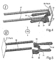
- FIGS. 4 , 5 show the release lever 29 in its two possible mounting positions I, II.
- the release lever 29 cooperates with the two tension springs 07 together.
- the spacing levers 30 are provided with ends 32 in the direction of the locatable receptacle 28 (cf. FIG. 3 ) in the first installation position I aligned.
- the release lever 29 is shown in its second possible installation position II , which is rotated to first installation position I only by 180 °.
- the distance levers 30 with their ends 32 in the direction of the stationary holder 27 see FIG. 3 ).
- the release lever 29 acts in this second mounting position II with the two compression springs 08 together. Since all parts are always inserted into each other, the conversion between the two installation positions I, II can be done without any tools in a particularly simple manner.
Landscapes
- Engineering & Computer Science (AREA)
- Life Sciences & Earth Sciences (AREA)
- Health & Medical Sciences (AREA)
- General Physics & Mathematics (AREA)
- Pathology (AREA)
- Analytical Chemistry (AREA)
- Biochemistry (AREA)
- General Health & Medical Sciences (AREA)
- Physics & Mathematics (AREA)
- Immunology (AREA)
- Chemical & Material Sciences (AREA)
- General Engineering & Computer Science (AREA)
- Mechanical Engineering (AREA)
- Molecular Biology (AREA)
- Biomedical Technology (AREA)
- Hydrology & Water Resources (AREA)
- Sampling And Sample Adjustment (AREA)
Description
- Die Erfindung bezieht sich auf einen automatisierten Mehrfach-Probenprozessor für fluidische Proben mit mehreren Kolbenpumpen, die eine Probenöffnung, ein zylindrisches Gehäuse und einen axial verschiebbaren Kolben aufweisen und die entfernbar in einem Tragrahmen gelagert sind, wobei jeder Kolben mit seinem von der Probenöffnung abgewandten freien Ende mit zumindest einer Spiralfeder verbunden ist, die im Tragrahmen abgestützt und in gespannter Ausgangslage mittels einer Verriegelung, die pro Kolbenpumpe einen durch einen Mitnehmer an einer drehbaren Welle auslösbaren Entriegelungshebel aufweist, fixierbar ist, wobei das Auslösen des Entriegelungshebels ein Verschieben des Kolbens im zylindrischen Gehäuse bewirkt.
- Automatisierte Mehrfach-Probenprozessoren in der Ausbildung als Mehrfach-Probensammler dienen der selbstständigen Probennahme von Fluiden, also Flüssigkeiten oder Gasen. Durch die Selbstständigkeit können auch Proben an unzugänglichen Orten genommen werden, beispielsweise können Wasserproben in der Tiefsee genommen werden, sogenannte "Wasserprobensammler", Akronym WPS. In der Regel wird bei solchen Experimenten am Probenort ein abgeschlossenes Wasservolumen mittels einer benthischen Kammer definiert und in der Kammer dann die Proben gezogen. Mit einem Mehrfach-Probensammler können mehrere Proben zeitgleich, aber auch sequenziell in vorgegebenen zeitlichen Abständen genommen werden (stationäre, aber zeitlich aufgelöste Probennahme). Kernpunkte bei der technischen Umsetzung von derartigen Mehrfach-Probensammlern sind die Probennehmer an sich und der automatische Antrieb bei der Probennahme. Die Erfindung beschäftigt sich speziell mit Kolbenpumpen als Probennehmer, deren Kolben über einen Federantrieb verschoben wird. Ein Federantrieb ermöglicht eine automatische Auslösung ohne direkte Stromversorgung. Diese ist dann nur noch für die Auslösung der Federn erforderlich, aber gegenüber einem Direktantrieb entsprechend kleiner dimensioniert, sodass der Mehrfach-Probensammler beispielswiese mittels Batterieversorgung autark an einem unzugänglichen Ort über einen größeren Zeitraum hinweg betrieben werden kann. Im Stand der Technik gibt es dazu unterschiedliche Lösungsansätze.
- Aus der
US 6 840 121 B2 ist beispielsweise ein autarker, selbstversorgender Mehrfach-Probensammler für Fluide, insbesondere Flüssigkeiten, bekannt, bei dem zehn Kolbenpumpen in Form von Spritzen in einem zylindrischen Tragrahmen vertikal angeordnet sind. Jeder Kolben ist mit einer Druckfeder vorgespannt. Bei der Auslösung entspannt sich die Feder und zieht dabei den Kolben zurück, sodass Flüssigkeit durch eine nadelförmige Öffnung der Spritze eingesogen wird. - Spiralfedern (oder auch Schraubenfedern) können als Druckfedern (Schraubendruckfedern) oder als Zugfedern (Schraubenzugfedern) ausgebildet sein. Druckfedern sind auf Druck belastbar und werden unter Druck zusammengedrückt (Aufnahme von potenzieller Energie). Bei Entlastung entspannen sie sich und können Arbeit verrichten (Abgabe der gespeicherten potenziellen Energie). Zugfedern sind auf Zug belastbar und werden unter Zug auseinandergezogen (Aufnahme von potenzieller Energie). Bei Entlastung ziehen sie sich zusammen und können Arbeit verrichten (Abgabe der gespeicherten potenziellen Energie).
- Kolbenpumpen bzw. Spritzen sind auch von den Mehrfach-Probensammlern speziell für den Einsatz in aquatischen Umgebungen bekannt, die beispielsweise in der
US 6 187 530 B1 und in dem Prospekt "Spritzenprobennehmer K/MT 115 - Meerestechnisches Gerät zur Wasserprobennahme" der Firma K.U.M Umwelt- und Meerestechnik Kiel GmbH (abgerufen im Internet unter der URL http://www.kum-kiel.de/fileadmin/pdf/de/Lander-Spritzenprobennehmer.pdf, Stand 13.04.2016) offenbart werden. Hier werden die Kolben der Spritzen aber motorisch und nicht federbetrieben verschoben. - In den nachfolgend genannten Druckschriften werden verschiedene Mehrfach-Probensammler mit Kolbenpumpen beschrieben. In der
US 4 116 067 A wird das von der Kolbenpumpe abgewandte Ende des Kolbens in einer spiralförmigen Kulisse geführt, sodass durch eine Drehung der Kolbenpumpe in der Kulissenebene der Kolben verschoben wird. In derUS 4 288 206 A werden die Kolben motorisch verschoben, in dem sie an einem gemeinsamen Auflagerbalken befestigt sind, der über einen Exzenter vertikal auf- und abbewegt wird. In derWO 96 / 30 740 A2 US 2010 / 0247378 A1 ist eine Kolbenpumpe bekannt, die sowohl zur Fluidaufnahme als auch zur Fluidabgabe dient. dabei wird der Kolben motorisch verschoben. Aus den DruckschriftenUS 5 201 720 A ,US 5 800 405 A undWO 2012 / 085 580 A1 sind Kolbenpumpen mit jeweils zwei Spiralfedern zur Verschiebung des Kolbens bekannt. Aus derUS 2006 / 0 069 354 A1 ist eine Kolbenpumpe in Spritzenform bekannt, bei der der Kolben mit vier Druckfedern belastet ist, wobei jeweils zwei Druckfedern gegeneinander arbeiten, sodass sie sich gegenseitig spannen. - Der der Erfindung nächstliegende Stand der Technik wird in der
US 3 884 081 A offenbart. Beschrieben wird ein automatisierter Mehrfach-Probenprozessor in der Ausbildung eines Mehrfach-Probensammlers für Luft mit vier Kolbenpumpen in Form von Spritzen, die eine Probenöffnung, ein zylindrisches Gehäuse und einen axial verschiebbaren Kolben aufweisen und die entfernbar in einem Tragrahmen gelagert sind. Jeder Kolben ist mit seinem von der Nadelöffnung als Probenöffnung abgewandten freien Ende mit einer ungeführten Spiralfeder in der Ausbildung einer Zugfeder verbunden, die im Tragrahmen abgestützt ist. In der gespannten Ausgangslage ist die Zugfeder auseinandergezogen und verriegelt, der Kolben ist in das zylindrische Gehäuse der Spritze eingefahren. Die Verriegelung weist einen Entriegelungshebel auf, der durch einen Mitnehmer an einer drehbaren Welle betätigt werden kann. Die drehbare Welle ist mit einem Motorantrieb verbunden. Bei einer Betätigung des Entriegelungshebels durch den Mitnehmer wird die fixierte Zugfeder entlastet, zieht sich zusammen und verschiebt den Kolben, indem sie ihn aus dem zylindrischen Gehäuse der Spritze herauszieht. Gleichzeitig wird über die Nadelöffnung, die sich in dem zu beprobenden Medium befindet, eine Luftprobe eingesogen. Eine Besonderheit dieses bekannten Mehrfach-Probensammlers liegt darin, dass gleichzeitig mit dem Ziehen der Luftprobe die Nadelöffnung verschlossen wird, um die gezogene Luftprobe sicher einzuschließen. - Alle beschriebenen Mehrfach-Probenprozessoren sind ausschließlich auf eine Probennahme ausgelegt, daher die häufige Bezeichnung "Probensammler". Da es bei vielen Einsatzfällen oft auch um Reaktionen von im Untersuchungsgebiet vorhandenen Organismen auf Beeinflussungen des umgebenden Mediums geht, ist es aber wünschenswert, dass auch Substanzen in die Umgebung abgegeben werden können. Optimal wäre daher eine kombinierte Probennahme und Probenabgabe. Ausgehend von der zuletzt genannten
US 3 884 081 A ist daher die Aufgabe darin zu sehen, den gattungsgemäßen Mehrfach-Probenprozessor so weiterzubilden, dass er sowohl für Probennahmen aus der Umgebung als auch für Probenabgaben in die Umgebung eingesetzt werden kann. Dabei soll seine Konstruktion aber möglichst einfach und variabel, darüber hinaus aber auch unempfindlich gegen Umwelteinflüsse und trotzdem kostengünstig sein. Die Lösung für diese Aufgabe ist dem Hauptanspruch zu entnehmen. Vorteilhafte Weiterbildungen der Erfindung werden in den Unteransprüchen aufgezeigt und im Folgenden im Zusammenhang mit der Erfindung näher erläutert. - Der beanspruchte Mehrfach-Probenprozessor ist erfindungsgemäß dadurch gekennzeichnet, dass jeder Kolben mit seinem von der Probenöffnung abgewandten freien Ende mit zwei Spiralfedern, die beide entweder als Zugfedern oder als Druckfedern ausgebildet sind, verbunden ist und dass pro Kolben entweder zwei Zugfedern und der Entriegelungshebel in einer ersten Einbaulage I vorgesehen sind, wobei das Auslösen des Entriegelungshebels durch den Mitnehmer das Hineinschieben des Kolbens in das zylindrische Gehäuse bewirkt, oder dass pro Kolben zwei Druckfedern und der Entriegelungshebel in einer zweiten Einbaulage II, die zur ersten Einbaulage I um 180° gedreht ist, vorgesehen sind, wobei das Auslösen des Entriegelungshebels durch den Mitnehmer das Herausschieben des Kolbens aus dem zylindrischen Gehäuse bewirkt.
- Der erfindungsgemäße Mehrfach-Probenprozessor ist umkehrbar ausgebildet, indem jede Kolbenpumpe individuell einstellbar ist, bei Auslösung entweder eine Probe aufzunehmen oder eine Probe abzugeben (Umkehrung). Dabei soll im vorliegenden Kontext unter dem Begriff "Probe" jede Art von flüssiger oder gasförmiger Substanzmenge verstanden werden. Also nicht nur solche, die einer späteren Analyse unterzogen werden, sondern auch solche Subtanzmengen, die der Vorbereitung/Beeinflussung der Analyse durch Veränderung der Umwelt dienen. Durch den erfindungsgemäßen Mehrfach-Probenprozessor ist es möglich, vollautomatisch ganze Prozessreihen mit zwei unterschiedlichen Prozessschritten durchzuführen. Beispielsweise kann zu einem Zeitpunkt t1 eine erste Kolbenpumpe mit einer toxischen Substanz gefüllt sein und diese bei Auslösung in ein abgeschlossenes Volumen abgeben. Zu Zeitpunkten t2, t3 und t4 werden dann durch die zweite, dritte und vierte Kolbenpumpe Proben gezogen, um die Auswirkung der toxischen Substanz auf die Organismen in dem beispielsweise in einer benthischen Kammer abgeschlossenen Volumen untersuchen zu können. Zu einem Zeitpunkt t5 wird dann eine fünfte Kolbenpumpe ausgelöst, die wiederum eine toxische Substanz in das Volumen abgibt. Zu den Zeitpunkten t6, t7 werden dann mit der sechsten und siebten Kolbenpumpe wiederum Proben gezogen. Alternativ ist es aber auch möglich nur zum Zeitpunkt t1 eine Substanz abzugeben und zu allen anderen Zeitpunkten Proben zu ziehen, um die zeitliche Auswirkung der Substanz zu dokumentieren.
- Alle Kolbenpumpe werden vor dem Auslösen in ihren Federn entsprechend vorgespannt. Die Zugfedern werden auseinandergezogen, die Druckfedern werden zusammengedrückt. Das alternierende Ziehen und Abgeben von Proben durch die entsprechend ausgerüsteten Kolbenpumpen ist nur eine beispielhafte Darstellung. jede andere Reihenfolge ist möglich. Ebenso ist ein gleichzeitiges Auslösen von einigen oder sogar allen Kolbenpumpen möglich. Der Auslösemodus richtet sich immer nach der Art der Anwendung des Mehrfach-Probenprozessors. Dabei wird jede Kolbenpumpe immer durch einen Mitnehmer auf der drehbaren Welle ausgelöst. Von der Winkellage des Mitnehmers auf der Welle ist die Auslösung jeder Kolbenpumpe relativ zu den benachbarten Kolbenpumpen abhängig. Die Schnelligkeit der Auslösungen ist wiederum von der Drehgeschwindigkeit der Welle abhängig.
- Besonders vorteilhaft ist bei dem erfindungsgemäßen Mehrfach-Probenprozessor die variable Ausrüstung jeder Kolbenpumpe zum Probennehmen oder -geben, die konstruktiv besonders einfach umgesetzt ist. Realisiert wird diese Umrüstbarkeit durch einen einfachen Entriegelungshebel, der in zwei Einbaulagen II angeordnet sein kann. Dabei ist er aber so gelagert, dass der ihm zugeordnete Mitnehmer auf der drehbaren Welle ihn in beiden Einbaulagen I, II auslösen kann. In der ersten Einbaulage I wirkt der Entriegelungshebel mit zwei Zugfedern zusammen. In der gespannten Ausganglage ist also der Kolben aus dem zylindrischen Gehäuse, das mit einer Substanz gefüllt ist, der Kolbenpumpe ausgefahren und die beiden Zugfedern sind auseinandergezogen und gespannt. Bei der Auslösung des Entriegelungshebels ziehen sie sich zusammen und ziehen dabei den Kolben in der Kolbenpumpe nach vorne. Die eingefüllte Substanz wird durch die Probenöffnung abgegeben. In der zweiten Einbaulage II ist der Entriegelungshebel um 180° versetzt (also umgekehrt) eingebaut und wirkt mit zwei Druckfedern zusammen. In der gespannten Ausgangslage ist der Kolben in das zylindrische Gehäuse, das leer ist, der Kolbenpumpe eingefahren und die beiden Druckfedern sind zusammengedrückt. Bei der Auslösung des Entriegelungshebels dehnen sie sich aus und ziehen dabei den Kolben in der Kolbenpumpe nach hinten. Durch die Probenöffnung wird eine Probe in das zylindrische Gehäuse eingesogen.
- Ein besonderer Vorteil des erfindungsgemäßen Mehrfach-Probenprozessors ist die freie Einstellbarkeit jeder Kolbenpumpe, nach der Auslösung als Probensammler oder als Probengeber zu arbeiten. Der erfindungsgemäße Mehrfach-Probenprozessor lässt somit einen modularen Aufbau zu. Dieser modulare Aufbau kann bevorzugt und vorteilhaft nach einer ersten vorteilhaften Ausgestaltung der Erfindung nach dadurch verbessert werden, dass jede Kolbenpumpe in einem eigenständigen Modulrahmen entfernbar gelagert ist, wobei der Modulrahmen im Tragrahmen entfernbar angeordnet ist, und dass sich die beiden Spiralfedern und der Entriegelungshebel in seiner ersten oder zweiten Einbaulage I, II im Modulrahmen abstützen. Jede Kolbenpumpe verfügt damit über ein eigenes Lagergestell und kann bereits in diesem vorgespannt werden, da sich die Federn dann auch im Modulrahmen abstützen. Alle Modulrahmen mit den vorgespannten Kolbenpumpen können dann in den Tragrahmen eingebaut werden. Durch die einfache Herausnahme jedes Modulrahmens kann der Umbau des Entriegelungshebels von der einen Einbaulage I, II in die andere Einbaulage I, II einfach vorgenommen werden. Dabei sind keinerlei Werkzeuge erforderlich. Es ist aber auch möglich, zwei Sorten von alternativ ausgerüsteten Modulrahmen vorrätig zu halten und diese dann entsprechend den Anforderungen (Anzahl der Kolbenpumpen zur Probenaufnahme, Anzahl der Kolbenpumpen zur Probenabgabe) im Tragrahmen zu kombinieren.
- Kolbenpumpen existieren in unterschiedlichen Ausführungsformen auf dem Markt. Die einfachste Form einer manuell betätigbaren Kolbenpumpe stellt die Spritze dar, wie sie aus der Medizin bekannt ist. Größere Spritzen treten in unterschiedlichen Ausführungsformen auf und werden entsprechend zu Forschungszwecken eingesetzt. Deshalb ist es gemäß einer nächsten Ausgestaltung der Erfindung besonders vorteilhaft und bevorzugt, wenn die Kolbenpumpe von einer Spritze mit einer Nadelöffnung als Probenöffnung gebildet ist und das zylindrische Gehäuse einen radialumlaufenden ersten Flansch und das freie Ende des Kolbens einen radial umlaufenden zweiten Flansch aufweist, wobei der erste Flansch in eine orstfeste Aufnahme und der zweite Flansch in eine ortsverschiebliche Aufnahme im Tragrahmen oder im Modulrahmen eingeschoben ist, und die beiden Spiralfedern mit ihren einen Enden mit dem Tragrahmen oder dem Modulrahmen und mit ihren anderen Enden mit der ortsverschieblichen Aufnahme verbunden sind. Bei dem beanspruchten Mehrfach-Probenprozessor kommen also bevorzugt Spritzen zum Einsatz, bei denen sowohl das Gehäuse als auch der Kolben einen radial umlaufenden Flansch aufweisen. Über den ersten Flansch wird das zylindrische Gehäuse der Spritze definiert im Tragrahmen oder im Modulrahmen gelagert. Über den zweiten Flansch wird der Kolben mit den beiden Federn verbunden und kann so sicher von diesen bei Entspannung im zylindrischen Gehäuse verschoben werden. Besonders vorteilhaft und bevorzugt ist es bei der Ausführung der Kolbenpumpe als Spritze darüber hinaus noch, wenn die Spritze aus Glas besteht und ein Hubvolumen von 50 ml aufweist, wobei der Kolben luftdicht im zylindrischen Gehäuse verschiebbar ist. Glasspritzen sind besonders stabil, aber auch hochtransparent, was eine leichte Beobachtung des Spritzeninneren ermöglicht (beispielsweise zur insitu-Beobachtung einer Probe noch innerhalb des Gehäuses, also ohne Auslassen der Probe in ein externes Gefäß). Ein Hubvolumen von 50 ml erlaubt eine Probengewinnung bzw. -abgabe in einem forschungstechnisch gut handhabbaren Maß. Das luftdichte Abschließen des Kolbens im zylindrischen Gehäuse gewährleistet, dass kein Probenmaterial verloren geht oder durch Nebenzug verunreinigt wird. Dabei ist der Einsatz von Gals für den luftdichten Sitz besonders geeignet, weil er durch Anschliff relativ einfach, aber dauerhaft herstellbar ist. Spritzen aus Kunstsoff neigen durch Alterung und Überbelastung zur Formveränderung und damit zur Undichtigkeit. Ein weiterer Vorteil des erfindungsgemäßen Mehrfach-Probenprozessors besteht in der einfachen Umrüstbarkeit für jede Kolbenpumpe zwischen Einsaug- und Ausstoßbetrieb. Dabei ist es gemäß einer nächsten Erfindungsausgestaltung besonders vorteilhaft und bevorzugt, wenn der Entriegelungshebel dreiteilig aus zwei Abstandshebeln und einem Nockenhebel ausgebildet ist, wobei der Nockenhebel gelenkig an den einen Enden der Abstandshebel angeordnet ist und die Abstandshebel in einer ersten Einbaulage I oder in einer zweiten Einbaulage II, die zur ersten Einbaulage I um 180° gedreht ist, mit dem Tragrahmen oder dem Modulrahmen verbunden sind. Derartige Teile lassen sich besonders einfach herstellen, beispielsweise durch Schneiden mit einem Wasserstrahl. Beide Teile werden gelenkig, d.h. drehbar ineinander eingehakt. Das Vermeiden von komplizierten Gelenken gewährleistet eine hohe Betriebssicherheit. Dies ist insbesondere beim autarken Einsatz des Mehrfach-Probenprozessors in unzugänglichen Gebieten, beispielsweise in großen Wassertiefen, wo er über einen längeren Zeitraum hinweg autark arbeiten muss, von großer Bedeutung. Gleiches gilt auch für den bevorzugten und vorteilhaften Einsatz einer drehbaren Welle, die als drehrichtungsunabhängige, umlauffähige Nockenwelle mit axial einstellbaren Nocken als Mitnehmer ausgebildet ist. Eine derartige Nockenwelle, die in beiden Umlaufrichtungen betrieben werden kann und auf der die Nocken an beliebigen Stellen positioniert werden können, ist handelsüblich beziehbar, kostengünstig und sehr robust. Gleiches gilt wiederum für die nächste bevorzugte Ausführungsform der Erfindung, bei der die drehbare Welle von einem druckneutralen Gleichstrommotor mit Inkrementalcoder antreibbar ist. Ein druckneutraler Gleichstrommotor ist mit Öl befüllt, wobei die Ölbefüllung mit einer druckfesten Rotationsdichtung abgedichtet ist. Er lässt sich auch in großen Wassertiefen zuverlässig in beiden Drehrichtungen einsetzen. Ein Inkrementalcoder betreibt den Gleichstrommotor als Schrittmotor, wodurch zeitlich sehr genau einstellbare und exakt zueinander beabstandete Auslösezeitpunkte festgelegt werden können. Insbesondere bei wissenschaftlichen Untersuchungen ist es von großer Bedeutung, die genauen Zeitpunkte der Probennahmen nach einer Kontamination zu kennen.
- Bezüglich der verwendbaren Materialien ist es bei dem beanspruchten Mehrfach-Probenprozessor bevorzugt und vorteilhaft, wenn der Modulrahmen und/oder die ortsfeste und die ortsverschiebliche Aufnahme aus faserverstärktem Kunststoff und/oder der Tragrahmen aus Metall und/oder die Spiralfedern aus Edelstahl bestehen. Der faserverstärkte Kunststoff lässt sich beispielsweise mittels Wasserstrahlschneiden besonders leicht verarbeiten. Ein einfaches Metall für den Tragrahmen kann einfach abgekantet werden. Edelstahl für die Spiralfedern verhindert deren Beschädigung im Betrieb. Ist ein Betrieb im Wasser, ggfs. sogar in Salzwasser, vorgesehen, so müssen natürlich alle verwendeten Komponenten wasser- und korrosionsfest sein. Spiralfedern aus Edelstahl sind bereits an sich sehr stabil und damit gut belastbar. Zur weiteren Verbesserung der Stabilität und insbesondere zur Vermeidung von Ausknickung kann gemäß einer nächsten Erfindungsausgestaltung noch bevorzugt und vorteilhaft vorgesehen sein, dass jede Spiralfeder (Zug und Druck) eine zentrale Führungsstange aufweist, die im Tragrahmen oder im Modulrahmen gelagert ist. Diese Führungsstange kann aus Metall bzw. Edelstahl oder auch aus Kunststoff bestehen.
- Bei dem beanspruchten Mehrfach-Probenprozessor sind immer mehrere Kolbenpumpen vorgesehen. Hierbei kann es sich je nach Anwendungsfall mindestens um zwei Kolbenpumpen (beide für Saug- oder Ausstoßbetrieb oder eine für Saugbetrieb und eine für Ausstoßbetrieb) bis zu zehn oder auch mehr Kolbenpumpen handeln (alle für Saug- oder Ausstoßbetrieb oder ein Teil für Saugbetrieb und ein Teil für Ausstoßbetrieb). Wie weiter oben in einem Ausführungsbeispiel für eine Anwendung bereits ausgeführt, ist es aber aus der Erfahrung besonders vorteilhaft und bevorzugt, wenn sieben Kolbenpumpen parallel nebeneinander im Tragrahmen gelagert sind. Schließlich ist es für Handhabbarkeit des beanspruchten Mehrfach-Probenprozessors nach der Erfindung noch besonders praktisch, wenn an der Oberseite des Tragrahmens ein Tragegriff angeordnet ist. Dadurch kann der Mehrfach-Probenprozessor besonders leicht transportiert und ggfs. an einem Seil in unzugänglichen Gebiete gehievt und gefiert werden. Weitere konstruktive Ausführungsdetails zum beanspruchten Mehrfach-Probenprozessor und zu seinen bevorzugten Ausführungsformen sind den nachfolgend beschrieben Ausführungsbeispielen zu entnehmen.
- Nachfolgend werden der automatisierte Mehrfach-Probenprozessor nach der Erfindung und seine vorteilhaften Modifikationen anhand der schematischen Figuren zum besseren Verständnis der Erfindung an Ausführungsbeispielen noch weitergehend erläutert. Dabei zeigt die
- Figur 1
- eine perspektivische Vorderansicht des Mehrfach-Probenprozessors,
- Figur 2
- eine perspektivische Explosionsdarstellung des Mehrfach-Probenprozessors,
- Figur 3
- eine perspektivische Explosionsdarstellung des Mehrfach-Probenprozessors im Bereich einer Kolbenpumpe,
- Figur 4
- eine Detailansicht für die erste Einbaulage I des Entriegelungshebels und
- Figur 5
- eine Detailansicht für die zweite, um 180° gedrehte Einbaulage II des Entriegelungshebels.
- Die
Figur 1 zeigt einen automatisierten Mehrfach-Probenprozessor 01 in der perspektivischen Vorderansicht. Der dargestellte Mehrfach-Probenprozessor 01 dient der Wasserprobennahme ("Wasserprobensammler" WPS) in der Tiefsee. Er umfasst im gezeigten Ausführungsbeispiel sieben Kolbenpumpen 02, die parallel nebeneinanderliegend in einem Tragrahmen 03 angeordnet sind. Zur einfachen Handhabung ist an der Oberseite des Tragrahmens 03 ein Tragegriff 04, beispielsweise ein Gurtband, angeordnet. Die Kolbenpumpen 02 sind in Klemmen 05 entfernbar gelagert und befinden sich in vorgespanntem Zustand. In der dargestellten Konfiguration ist zu erkennen, dass die linke Kolbenpumpe 02 mit einer Substanz gefüllt ist, die bei Auslösung in die Umgebung abgegeben wird. Die anderen Kolbenpumpen 02 sind leer und werden bei Auslösung zur Wasserprobennahme aus der Umgebung aufgezogen. - In der
Figur 1 ist weiterhin zu erkennen, dass jede Kolbenpumpe 02 von zwei Spiralfedern 06 umgeben ist. Dabei handelt es sich bei der linken Kolbenpumpe 02 um zwei Zugfedern 07 und bei den restlichen Kolbenpumpen 02 jeweils um zwei Druckfedern 08. Außerdem ist für jede Kolbenpumpe 02 die Nockenplatte 33 (vergleicheFigur 3 ) zu erkennen, der der Auslösung der Spiralfedern 06 durch die Nocken 12 der Nockenwelle 10 (vergleicheFigur 2 ) dient. - In der
Figur 2 ist eine Explosionsdarstellung des automatisierten Mehrfach-Probenprozessors 01 gemäßFigur 1 aufgezeigt. Zu erkennen sind der Tragrahmen 03 und eine dahinter angeordnete drehbare Welle 09 in Form einer Nockenwelle 10, die eine Vielzahl von Mitnehmern 11 in der Ausbildung als Nocken 12 aufweist. Die Nocken 12 greifen durch Aussparungen 13 im Tragrahmen 03 hindurch. Durch diese Aussparungen ist auch ein Antrieb 14 für die drehbare Welle 09 zu erkennen, bei dem es sich im gewählten Ausführungsbeispiel um einen druckneutralen Gleichstrommotor 15 mit Inkrementalcoder handelt. Zu erkennen sind ebenfalls sieben eigenständige Modulrahmen 16, in denen die Kolbenpumpen 02 und die Spiralfedern 06 angeordnet sind. Alle Modulrahmen 16 werden auf dem Tragrahmen 03 gehaltert und mit Seitenteilen 17 stabilisiert. - Die
Figur 3 zeigt eine Explosionsdarstellung eines Modulrahmens 16 mit einer Kolbenpumpe 02. Die Kolbenpumpe 02 ist im gezeigten Ausführungsbeispiel als Spritze 18 aus Glas ausgebildet. Sie besteht aus einer Probenöffnung 19, einem zylindrischen Gehäuse 20 und einem axial verschiebbaren Kolben 21. Auf der Probenöffnung 19 in Form einer Nadelöffnung 22 befindet sich ein gebogenes Ansatzstück 23 zum gelenkten Ausstoßen bzw. Ansaugen von Probenwasser. Weiterhin sind ein radialumlaufender erster Flansch 24 am zylindrischen Gehäuse 20 und ein radialumlaufender zweiter Flansch 25 am Kolben 21 zu erkennen. Dabei ist der zweite Flansch 25 an dem von der Probenöffnung 19 abgewandten freien Ende 41 des Kolbens 21 angeordnet, an dem auch die Spiralfedern 06 über die ortsverschiebliche Aufnahme 28 (vergleiche Beschreibung Modulrahmen 16, siehe unten) mit dem Kolben 21 verbunden sind. Beiderseits der Spritze 18 sind zwei Führungsstangen 26 angeordnet, die im Tragrahmen 03 oder im Modulrahmen 16 gelagert sind und auf denen die Spiralfedern 06 geführt werden. Gezeigt ist die linke Kolbenpumpe 02 gemäßFigur 1 , sodass es sich bei den beiden Spiralfedern 06 um die Zugfedern 07 handelt. Der Kolben 21 ist maximal aus dem zylindrischen Gehäuse 20 herausgezogen dargestellt. Die Zugfedern 07 (analog Druckfedern 08) sind mit ihren einen Ende 42 mit dem Tragrahmen 03 bzw. dem Modulrahmen 16 bzw. mit der ortsfesten Aufnahme 27 und mit ihren anderen Enden 43 mit der ortsverschieblichen Aufnahme 28 fest verbunden. - Unterhalb der Kolbenpumpe 02 ist der Modulrahmen 16 dargestellt, der in den Tragrahmen 03 eingeschraubt ist. Zu erkennen ist die Klemme 05, in die Spritze 18 entfernbar eingeklemmt wird. Weiterhin ist eine ortsfeste Aufnahme 27 im Modulrahmen 16 dargestellt, in die der erste Flansch 24 am zylindrischen Gehäuse der Spritze 18 eingeschoben wird. Damit ist das zylindrische Gehäuse 20 der Spritze 18 sicher im Modulrahmen 16 fixiert. Weiterhin befindet sich eine ortsverschiebliche Aufnahme 28 im Modulrahmen 16, in die der zweite Flansch 25 am Kolben 21 eingeschoben wird. Mit diesem ortsverschieblichen Flansch 25 sind die beiden Zugfedern 07 verbunden. Bei einer Auslösung der Zugfedern 07 ziehen diese sich zusammen und ziehen dabei die ortsverschiebliche Aufnahme 28 und damit den Kolben 21 in Richtung auf die Probenöffnung 19. Der Inhalt der Spritze 18 wird durch das Ansatzstück 23 ausgestoßen. Die Zugfedern 07 bzw. Druckfedern 08 stützen sich im Modulrahmen 16 ab. Da dieser fest in den Tragrahmen 03 eingebaut ist, stützen sich die Spiralfedern 06 somit auch im Tragrahmen 03 ab. Die Zugfedern 07 bzw. Druckfedern 08 sind mit ihren anderen Enden 43 mit Nasen 44 an der ortsverschieblichen Aufnahme 28 fest verbunden.
- Unterhalb des Modulrahmens 16 ist eine Verriegelung mit einem Entriegelungshebel 29 zum Auslösen der Spiralfedern 06 dargestellt. Er ist dreiteilig aufgebaut und besteht aus zwei Abstandshebeln 30 und einem Nockenhebel 31. Der Nockenhebel 31 ist gelenkig an einem Ende 32 des Abstandshebels 30 angeordnet. Dabei besteht das Gelenk aus Zapfen 34 an den Abstandshebeln 30 und Schlitze 35 in dem Nockenhebel 31. Weiterhin weist der Nockenhebel 31 zwei Aussparungen 36 auf. Diese werden auf erste Ansätze 37 an zwei Rahmenstreben 38 des Modulrahmen 16 in der ersten Einbaulage I (Zugfedern, vergleiche
Figur 4 ) und auf zweite Ansätze 39 an den Rahmenstreben 38 in der zweiten, um 180° gedrehten Einbaulage II (Druckfedern, vergleicheFigur 5 ) gesteckt. Diese gelenkigen Verbindungen bilden die Lagerstelle für die Drehbewegung des Nockenhebels 31 bei der Auslösung. Der Nockenhebel 31 weist eine Nockenplatte 33 auf, gegen die die Nocke 12 der Nockenwelle 10 wirkt. Der Entriegelungshebel 29 befindet sich im Modulrahmen 16 unterhalb der ortsverschieblichen Aufnahme 28 der Spritze 18 und wird in verriegelter Position durch Spannfedern 45 belastet. Im Falle der Auslösung wird der Nockenhebel 31 gegen die Federkraft kurzzeitig hochgedrückt und entriegelt die beiden Abstandshebel 30, die mit Absätzen 40 an ihren einen Enden 32 die ortsverschiebliche Aufnahme 28 festhalten. Diese und die damit verbundenen Spiralfedern 06 werden beim Auslösen freigegeben. - Die
Figuren 4, 5 zeigen den Entriegelungshebel 29 in seinen beiden möglichen Einbaulagen I, II. In derFigur 4 wirkt der Entriegelungshebel 29 mit den zwei Zugfedern 07 zusammen. Die Abstandshebel 30 sind mit Enden 32 in Richtung auf die ortsverschiebliche Aufnahme 28 (vergleicheFigur 3 ) in der ersten Einbaulage I ausgerichtet. In derFigur 5 ist der Entriegelungshebel 29 in seiner zweiten möglichen Einbaulage II aufgezeigt, die zu ersten Einbaulage I lediglich um 180° gedreht ist. In der zweiten Einbaulage II sind die Abstandshebel 30 mit ihren Enden 32 in Richtung auf die orstfeste Aufnahme 27 (vergleicheFigur 3 ) ausgerichtet. Der Entriegelungshebel 29 wirkt in dieser zweiten Einbaulage II mit den beiden Druckfedern 08 zusammen. Da alle Teile immer nur ineinandergesteckt sind, kann der Umbau zwischen den beiden Einbaulagen I, II ohne jegliches Werkzeug in besonders einfacher Weise erfolgen. -
- 01
- automatisierter Mehrfach-Probenprozessor
- 02
- Kolbenpumpe
- 03
- Tragrahmen
- 04
- Tragegriff
- 05
- Klemme
- 06
- Spiralfeder
- 07
- Zugfeder
- 08
- Druckfeder
- 09
- drehbare Welle
- 10
- Nockenwelle
- 11
- Mitnehmer
- 12
- Nocke
- 13
- Aussparung in 03
- 14
- Antrieb
- 15
- Gleichstrommotor
- 16
- Modulrahmen
- 17
- Seitenteil von 03
- 18
- Spritze
- 19
- Probenöffnung
- 20
- zylindrisches Gehäuse
- 21
- Kolben
- 22
- Nadelöffnung
- 23
- Ansatzstück
- 24
- erster Flansch an 20
- 25
- zweiter Flansch an 21
- 26
- Führungsstange
- 27
- ortsfeste Aufnahme für 24
- 28
- ortsverschiebliche Aufnahme für 21
- 29
- Entriegelungshebel
- 30
- Abstandshebel
- 31
- Nockenhebel
- 32
- eines Ende von 30
- 33
- Nockenplatte
- 34
- Zapfen an 30
- 35
- Schlitz in 31
- 36
- Aussparung in 31
- 37
- erster Ansatz an 38
- 38
- Rahmenstrebe
- 39
- zweiter Ansatz an 38
- 40
- Absatz an 30
- 41
- von 19 abgewandtes freies Ende von 21
- 42
- eines Ende von 06, 07, 08
- 43
- anderes Ende von 06, 07, 08
- 44
- Nase an 28
- 45
- Spannfeder
- I
- erste Einbaulage von 29 (Zugfedern 07, Ausstoßen)
- II
- zweite Einbaulage von 29 (Druckfedern 08, Ansaugen)
Claims (11)
- Automatisierter Mehrfach- Probenprozessor (01) für fluidische Proben mit mehreren Kolbenpumpen (02), die eine Probenöffnung (19), ein zylindrisches Gehäuse (20) und einen axial verschiebbaren Kolben (21) aufweisen und die entfernbar in einem Tragrahmen (03) gelagert sind, wobei jeder Kolben (21) mit seinem von der Probenöffnung (19) abgewandten freien Ende (41) mit zumindest einer Spiralfeder (06) verbunden ist, die im Tragrahmen (03) abgestützt und in gespannter Ausgangslage mittels einer Verriegelung, die pro Kolbenpumpe (02) einen durch einen Mitnehmer (11) an einer drehbaren Welle (09) auslösbaren Entriegelungshebel (29) aufweist, fixierbar ist, wobei das Auslösen des Entriegelungshebels (29) ein Verschieben des Kolbens (21) im zylindrischen Gehäuse (20) bewirkt,
dadurch gekennzeichnet, dass
jeder Kolben (21) mit seinem von der Probenöffnung (19) abgewandten freien Ende (41) mit zwei Spiralfedern (06), die beide entweder als Zugfedern (07) oder als Druckfedern (08) ausgebildet sind, verbunden ist und dass pro Kolben (21) entweder zwei Zugfedern (07) und der Entriegelungshebel (29) in einer ersten Einbaulage I vorgesehen sind, wobei das Auslösen des Entriegelungshebels (29) durch den Mitnehmer (11) das Hineinschieben des Kolbens (21) in das zylindrische Gehäuse (20) bewirkt, oder dass pro Kolben (21) zwei Druckfedern (08) und der Entriegelungshebel (29) in einer zweiten Einbaulage II, die zur ersten Einbaulage I um 180° gedreht ist, vorgesehen sind, wobei das Auslösen des Entriegelungshebels (29) durch den Mitnehmer (11) das Herausschieben des Kolbens (21) aus dem zylindrischen Gehäuse (20) bewirkt. - Automatisierter Mehrfach-Probenprozessor (01) nach Anspruch 1,
dadurch gekennzeichnet, dass
jede Kolbenpumpe (02) in einem eigenständigen Modulrahmen (16) entfernbar gelagert ist, wobei der Modulrahmen (16) im Tragrahmen (03) entfernbar angeordnet ist, und dass sich die beiden Spiralfedern (06, 07, 08) und der Entriegelungshebel (29) in seiner ersten oder zweiten Einbaulage I, II im Modulrahmen (16) abstützen. - Automatisierter Mehrfach-Probenprozessor (01) nach Anspruch 1 oder 2,
dadurch gekennzeichnet, dass
die Kolbenpumpe (02) von einer Spritze (18) mit einer Nadelöffnung (22) als Probenöffnung (19) gebildet ist und das zylindrische Gehäuse (20) einen radialumlaufenden ersten Flansch (24) und das freie Ende (41) des Kolbens (21) einen radial umlaufenden zweiten Flansch (25) aufweist, wobei der erste Flansch (24) in eine orstfeste Aufnahme (27) und der zweite Flansch (25) in eine ortsverschiebliche Aufnahme (28) im Tragrahmen (03) oder im Modulrahmen (16) eingeschoben ist, und die beiden Spiralfedern (06, 07, 08) mit ihren einen Enden (42) mit dem Tragrahmen (03) oder dem Modulrahmen (16) und mit ihren anderen Enden (43) mit der ortsverschieblichen Aufnahme (28) verbunden sind. - Automatisierter Mehrfach-Probenprozessor (01) nach Anspruch 3,
dadurch gekennzeichnet, dass
die Spritze (18) aus Glas besteht und ein Hubvolumen von 50 ml aufweist, wobei der Kolben (21) luftdicht im zylindrischen Gehäuse (20) verschiebbar ist. - Automatisierter Mehrfach-Probenprozessor (01) nach einem der vorangehenden Ansprüche,
dadurch gekennzeichnet, dass
der Entriegelungshebel (29) dreiteilig aus zwei Abstandshebeln (30) und einem Nockenhebel (31) ausgebildet ist, wobei der Nockenhebel (31) gelenkig an den einen Enden (32) der Abstandshebel (30) angeordnet ist und die Abstandshebel (30) in einer ersten Einbaulage I oder in einer zweiten Einbaulage II, die zur ersten Einbaulage I um 180° gedreht ist, mit dem Tragrahmen (03) oder dem Modulrahmen (16) verbunden sind. - Automatisierter Mehrfach-Probenprozessor (01) nach einem der vorangehenden Ansprüche,
dadurch gekennzeichnet, dass
die drehbare Welle (09) als drehrichtungsunabhängige, umlauffähige Nockenwelle (10) mit axial einstellbaren Nocken (12) als Mitnehmer (11) ausgebildet ist. - Automatisierter Mehrfach-Probenprozessor (01) nach einem der vorangehenden Ansprüche,
dadurch gekennzeichnet, dass
die drehbare Welle (09) von einem druckneutralen Gleichstrommotor (15) mit Inkrementalcoder antreibbar ist. - Automatisierter Mehrfach-Probenprozessor (01) nach einem der vorangehenden Ansprüche 2 bis 7,
dadurch gekennzeichnet, dass
der Modulrahmen (16) und/oder die ortsfeste und die ortsverschiebliche Aufnahme (27, 28) aus faserverstärktem Kunststoff und/oder der Tragrahmen (03) aus Metall und/oder die Spiralfedern (06, 07, 08) aus Edelstahl bestehen. - Automatisierter Mehrfach-Probenprozessor (01) nach einem der vorangehenden Ansprüche,
dadurch gekennzeichnet, dass
jede Spiralfeder (06, 07, 08) eine zentrale Führungsstange (26) aufweist, die im Tragrahmen (03) oder im Modulrahmen (16) gelagert ist. - Automatisierter Mehrfach-Probenprozessor (01) nach einem der vorangehenden Ansprüche,
dadurch gekennzeichnet, dass
sieben Kolbenpumpen (02) parallel nebeneinander im Tragrahmen (03) gelagert sind. - Automatisierter Mehrfach-Probenprozessor (01) nach einem der vorangehenden Ansprüche,
dadurch gekennzeichnet, dass
an der Oberseite des Tragrahmens (03) ein Tragegriff (04) angeordnet ist.
Applications Claiming Priority (2)
| Application Number | Priority Date | Filing Date | Title |
|---|---|---|---|
| DE102016005055.1A DE102016005055B3 (de) | 2016-04-26 | 2016-04-26 | Automatisierter Mehrfach-Probenprozessor mit mehreren Kolbenpumpen |
| PCT/DE2017/100290 WO2017186214A1 (de) | 2016-04-26 | 2017-04-11 | Automatisierter mehrfach-probenprozessor mit mehreren kolbenpumpen |
Publications (2)
| Publication Number | Publication Date |
|---|---|
| EP3449233A1 EP3449233A1 (de) | 2019-03-06 |
| EP3449233B1 true EP3449233B1 (de) | 2019-07-31 |
Family
ID=56801223
Family Applications (1)
| Application Number | Title | Priority Date | Filing Date |
|---|---|---|---|
| EP17723254.3A Active EP3449233B1 (de) | 2016-04-26 | 2017-04-11 | Automatisierter mehrfach-probenprozessor mit mehreren kolbenpumpen |
Country Status (5)
| Country | Link |
|---|---|
| US (1) | US10393630B2 (de) |
| EP (1) | EP3449233B1 (de) |
| DE (1) | DE102016005055B3 (de) |
| DK (1) | DK3449233T3 (de) |
| WO (1) | WO2017186214A1 (de) |
Families Citing this family (10)
| Publication number | Priority date | Publication date | Assignee | Title |
|---|---|---|---|---|
| CN105842013B (zh) * | 2016-04-28 | 2019-03-19 | 上海科勒电子科技有限公司 | 一种集液装置及包括该集液装置的智能马桶 |
| CN106840774A (zh) * | 2017-02-23 | 2017-06-13 | 水利部交通运输部国家能源局南京水利科学研究院 | 不同深度多点平行进样水平向水样采集器 |
| CN108709768A (zh) * | 2018-03-08 | 2018-10-26 | 余维胜 | 一种工业污水分散式抽样设备 |
| CN109724846A (zh) * | 2019-02-18 | 2019-05-07 | 徐明立 | 一种水文采集的连续采样装置 |
| CN112901478A (zh) * | 2021-03-01 | 2021-06-04 | 北京天地玛珂电液控制系统有限公司 | 柱塞泵 |
| CN113203602B (zh) * | 2021-05-24 | 2022-10-04 | 重庆医科大学附属第一医院 | 一种用于医学检验的取样装置 |
| CN113699027B (zh) * | 2021-08-30 | 2023-07-11 | 成都微康生物科技有限公司 | 一种全自动pcr分析系统活塞升降与封膜刺破装置 |
| CN115163441B (zh) * | 2022-08-04 | 2023-08-04 | 安徽工程大学 | 一种基于永磁铁驱动的柱塞变量液压泵 |
| CN115575191B (zh) * | 2022-12-05 | 2023-05-09 | 启东胜科水务有限公司 | 一种水文检测取样装置 |
| FR3143750A1 (fr) * | 2022-12-15 | 2024-06-21 | Suez International | Dispositif de prélèvement de fluide à déclenchement automatique et procédé de prélèvement associé |
Family Cites Families (15)
| Publication number | Priority date | Publication date | Assignee | Title |
|---|---|---|---|---|
| US3884081A (en) | 1974-06-24 | 1975-05-20 | California Inst Of Techn | Automated sequential air sampler |
| US4116067A (en) * | 1977-09-06 | 1978-09-26 | Aerovironment Inc. | Fluid sampling devices |
| US4288206A (en) * | 1979-08-15 | 1981-09-08 | Tigwell David C | Automatic multiple water sampler |
| US5201720A (en) * | 1992-04-21 | 1993-04-13 | Joseph Borgia | Syringe holding and ejecting assembly |
| US5553508A (en) * | 1995-03-24 | 1996-09-10 | University Corporation For Atmospheric Research | Portable intelligent whole air sampling system |
| US5800405A (en) * | 1995-12-01 | 1998-09-01 | I-Flow Corporation | Syringe actuation device |
| WO1999018421A1 (en) | 1997-10-03 | 1999-04-15 | Monterey Bay Aquarium Research Institute | Aquatic autosampler device |
| US6840121B2 (en) | 2002-07-18 | 2005-01-11 | University Of Florida Reasearch Foundation, Inc. | Self-powered fluid sampler |
| US7292096B2 (en) | 2004-06-21 | 2007-11-06 | Samsung Electronics Co., Ltd. | Amplifier |
| US20060069354A1 (en) * | 2004-09-30 | 2006-03-30 | Buenger David R | Syringe activation device |
| US8703071B2 (en) * | 2007-10-10 | 2014-04-22 | Etp Mass Spectrometry Pty Ltd | Syringe system |
| DE102009032097B3 (de) * | 2009-07-03 | 2010-06-17 | Stiftung Alfred-Wegener-Institut Für Polar- Und Meeresforschung | Vorrichtung zur Wasserprobennahme |
| GB201021717D0 (en) * | 2010-12-22 | 2011-02-02 | Owen Mumford Ltd | Autoinjectors |
| FR3004257B1 (fr) | 2013-04-04 | 2015-11-20 | Opta Periph | Dispositif augmentateur de pression d'echantillonnage de gnl |
| ITPI20130042A1 (it) | 2013-05-14 | 2014-11-15 | Benedetto Allotta | Struttura perfezionata di campionatore per ispezioni subacquee |
-
2016
- 2016-04-26 DE DE102016005055.1A patent/DE102016005055B3/de not_active Expired - Fee Related
-
2017
- 2017-04-11 EP EP17723254.3A patent/EP3449233B1/de active Active
- 2017-04-11 DK DK17723254.3T patent/DK3449233T3/da active
- 2017-04-11 WO PCT/DE2017/100290 patent/WO2017186214A1/de not_active Ceased
- 2017-04-11 US US16/095,966 patent/US10393630B2/en active Active
Non-Patent Citations (1)
| Title |
|---|
| None * |
Also Published As
| Publication number | Publication date |
|---|---|
| US10393630B2 (en) | 2019-08-27 |
| DE102016005055B3 (de) | 2016-09-15 |
| US20190137365A1 (en) | 2019-05-09 |
| WO2017186214A1 (de) | 2017-11-02 |
| EP3449233A1 (de) | 2019-03-06 |
| DK3449233T3 (da) | 2019-09-23 |
Similar Documents
| Publication | Publication Date | Title |
|---|---|---|
| DE102016005055B3 (de) | Automatisierter Mehrfach-Probenprozessor mit mehreren Kolbenpumpen | |
| EP2449358B1 (de) | Vorrichtung zur wasserprobennahme | |
| DE69228979T2 (de) | Vorrichtung und Verfahren zur Extraktion mit überkritischen Fluiden | |
| DE3417757C2 (de) | Injektionsspritze | |
| DE1924502C3 (de) | Vorrichtung zur Entnahme eines Druckmittels aus einem Hydraulikkreislauf | |
| DE102009016590A1 (de) | Dosiervorrichtung | |
| DE19603290A1 (de) | Steintrimmer | |
| DE102013106534A1 (de) | Chromatographiepipettenspitze | |
| DE60127433T2 (de) | Pipettiervorrichtung mit spülung | |
| DE102005039175A1 (de) | Vorrichtung und Verfahren zum Abtrennen von magnetischen Partikeln aus einer Flüssigkeit | |
| DE102015105306A1 (de) | Probenentnahmevorrichtung und Reihenanordnung daraus | |
| DE202019106655U1 (de) | Pumpenverschluss | |
| EP2957886B1 (de) | Einrichtung zur Exposition von Probenkörpern in einer Flüssigkeit | |
| DE1164377B (de) | Filterverschluss | |
| DE102011106542B4 (de) | Antriebseinrichtung zum Erzeugen einer periodischen, linearen Bewegung und einer gleichzeitigen Drehbewegung eines langgestreckten Maschinenelements | |
| WO2011141251A1 (de) | Mikromanipulationssystem mit schutzvorrichtung für kapillaren | |
| EP1682275A1 (de) | Probenpipette | |
| EP2886756B1 (de) | Schliesszylinder | |
| DE2455901A1 (de) | Verfahren und vorrichtung zum fuellen und verschliessen einer gaskammer, insbesondere einer gasfeder | |
| DE69200368T2 (de) | Drosselklappen-Rückschlagventil. | |
| DE102008048866A1 (de) | Vorrichtung und Verfahren zum Entnehmen von Material eines Material-Reservoirs | |
| DE2738321A1 (de) | Verbindungskupplung fuer rohrteile | |
| DE4312209B4 (de) | Kupplungskugelträger für Fahrzeug-Anhängerkupplungen | |
| EP2024726B1 (de) | Kolbenspritze zur entnahme von proben in einer leitung geführten gasförmigen oder flüssigen mediums | |
| DE2147363C3 (de) | Vorrichtung zum Fernbedienen einer Pipette bei der Überführung von kleinen Flüssigkeitsmengen |
Legal Events
| Date | Code | Title | Description |
|---|---|---|---|
| STAA | Information on the status of an ep patent application or granted ep patent |
Free format text: STATUS: UNKNOWN |
|
| STAA | Information on the status of an ep patent application or granted ep patent |
Free format text: STATUS: THE INTERNATIONAL PUBLICATION HAS BEEN MADE |
|
| PUAI | Public reference made under article 153(3) epc to a published international application that has entered the european phase |
Free format text: ORIGINAL CODE: 0009012 |
|
| STAA | Information on the status of an ep patent application or granted ep patent |
Free format text: STATUS: REQUEST FOR EXAMINATION WAS MADE |
|
| 17P | Request for examination filed |
Effective date: 20181010 |
|
| AK | Designated contracting states |
Kind code of ref document: A1 Designated state(s): AL AT BE BG CH CY CZ DE DK EE ES FI FR GB GR HR HU IE IS IT LI LT LU LV MC MK MT NL NO PL PT RO RS SE SI SK SM TR |
|
| AX | Request for extension of the european patent |
Extension state: BA ME |
|
| GRAP | Despatch of communication of intention to grant a patent |
Free format text: ORIGINAL CODE: EPIDOSNIGR1 |
|
| STAA | Information on the status of an ep patent application or granted ep patent |
Free format text: STATUS: GRANT OF PATENT IS INTENDED |
|
| DAV | Request for validation of the european patent (deleted) | ||
| DAX | Request for extension of the european patent (deleted) | ||
| INTG | Intention to grant announced |
Effective date: 20190416 |
|
| GRAA | (expected) grant |
Free format text: ORIGINAL CODE: 0009210 |
|
| STAA | Information on the status of an ep patent application or granted ep patent |
Free format text: STATUS: THE PATENT HAS BEEN GRANTED |
|
| AK | Designated contracting states |
Kind code of ref document: B1 Designated state(s): AL AT BE BG CH CY CZ DE DK EE ES FI FR GB GR HR HU IE IS IT LI LT LU LV MC MK MT NL NO PL PT RO RS SE SI SK SM TR |
|
| REG | Reference to a national code |
Ref country code: CH Ref legal event code: EP Ref country code: GB Ref legal event code: FG4D Free format text: NOT ENGLISH |
|
| REG | Reference to a national code |
Ref country code: AT Ref legal event code: REF Ref document number: 1161427 Country of ref document: AT Kind code of ref document: T Effective date: 20190815 |
|
| REG | Reference to a national code |
Ref country code: IE Ref legal event code: FG4D Free format text: LANGUAGE OF EP DOCUMENT: GERMAN |
|
| REG | Reference to a national code |
Ref country code: DE Ref legal event code: R096 Ref document number: 502017001901 Country of ref document: DE |
|
| REG | Reference to a national code |
Ref country code: DK Ref legal event code: T3 Effective date: 20190916 |
|
| REG | Reference to a national code |
Ref country code: NL Ref legal event code: MP Effective date: 20190731 |
|
| REG | Reference to a national code |
Ref country code: LT Ref legal event code: MG4D |
|
| PG25 | Lapsed in a contracting state [announced via postgrant information from national office to epo] |
Ref country code: HR Free format text: LAPSE BECAUSE OF FAILURE TO SUBMIT A TRANSLATION OF THE DESCRIPTION OR TO PAY THE FEE WITHIN THE PRESCRIBED TIME-LIMIT Effective date: 20190731 Ref country code: LT Free format text: LAPSE BECAUSE OF FAILURE TO SUBMIT A TRANSLATION OF THE DESCRIPTION OR TO PAY THE FEE WITHIN THE PRESCRIBED TIME-LIMIT Effective date: 20190731 Ref country code: NO Free format text: LAPSE BECAUSE OF FAILURE TO SUBMIT A TRANSLATION OF THE DESCRIPTION OR TO PAY THE FEE WITHIN THE PRESCRIBED TIME-LIMIT Effective date: 20191031 Ref country code: FI Free format text: LAPSE BECAUSE OF FAILURE TO SUBMIT A TRANSLATION OF THE DESCRIPTION OR TO PAY THE FEE WITHIN THE PRESCRIBED TIME-LIMIT Effective date: 20190731 Ref country code: SE Free format text: LAPSE BECAUSE OF FAILURE TO SUBMIT A TRANSLATION OF THE DESCRIPTION OR TO PAY THE FEE WITHIN THE PRESCRIBED TIME-LIMIT Effective date: 20190731 Ref country code: PT Free format text: LAPSE BECAUSE OF FAILURE TO SUBMIT A TRANSLATION OF THE DESCRIPTION OR TO PAY THE FEE WITHIN THE PRESCRIBED TIME-LIMIT Effective date: 20191202 Ref country code: BG Free format text: LAPSE BECAUSE OF FAILURE TO SUBMIT A TRANSLATION OF THE DESCRIPTION OR TO PAY THE FEE WITHIN THE PRESCRIBED TIME-LIMIT Effective date: 20191031 Ref country code: NL Free format text: LAPSE BECAUSE OF FAILURE TO SUBMIT A TRANSLATION OF THE DESCRIPTION OR TO PAY THE FEE WITHIN THE PRESCRIBED TIME-LIMIT Effective date: 20190731 |
|
| PG25 | Lapsed in a contracting state [announced via postgrant information from national office to epo] |
Ref country code: RS Free format text: LAPSE BECAUSE OF FAILURE TO SUBMIT A TRANSLATION OF THE DESCRIPTION OR TO PAY THE FEE WITHIN THE PRESCRIBED TIME-LIMIT Effective date: 20190731 Ref country code: ES Free format text: LAPSE BECAUSE OF FAILURE TO SUBMIT A TRANSLATION OF THE DESCRIPTION OR TO PAY THE FEE WITHIN THE PRESCRIBED TIME-LIMIT Effective date: 20190731 Ref country code: GR Free format text: LAPSE BECAUSE OF FAILURE TO SUBMIT A TRANSLATION OF THE DESCRIPTION OR TO PAY THE FEE WITHIN THE PRESCRIBED TIME-LIMIT Effective date: 20191101 Ref country code: AL Free format text: LAPSE BECAUSE OF FAILURE TO SUBMIT A TRANSLATION OF THE DESCRIPTION OR TO PAY THE FEE WITHIN THE PRESCRIBED TIME-LIMIT Effective date: 20190731 Ref country code: LV Free format text: LAPSE BECAUSE OF FAILURE TO SUBMIT A TRANSLATION OF THE DESCRIPTION OR TO PAY THE FEE WITHIN THE PRESCRIBED TIME-LIMIT Effective date: 20190731 Ref country code: IS Free format text: LAPSE BECAUSE OF FAILURE TO SUBMIT A TRANSLATION OF THE DESCRIPTION OR TO PAY THE FEE WITHIN THE PRESCRIBED TIME-LIMIT Effective date: 20191130 |
|
| PG25 | Lapsed in a contracting state [announced via postgrant information from national office to epo] |
Ref country code: TR Free format text: LAPSE BECAUSE OF FAILURE TO SUBMIT A TRANSLATION OF THE DESCRIPTION OR TO PAY THE FEE WITHIN THE PRESCRIBED TIME-LIMIT Effective date: 20190731 |
|
| PG25 | Lapsed in a contracting state [announced via postgrant information from national office to epo] |
Ref country code: PL Free format text: LAPSE BECAUSE OF FAILURE TO SUBMIT A TRANSLATION OF THE DESCRIPTION OR TO PAY THE FEE WITHIN THE PRESCRIBED TIME-LIMIT Effective date: 20190731 Ref country code: RO Free format text: LAPSE BECAUSE OF FAILURE TO SUBMIT A TRANSLATION OF THE DESCRIPTION OR TO PAY THE FEE WITHIN THE PRESCRIBED TIME-LIMIT Effective date: 20190731 Ref country code: IT Free format text: LAPSE BECAUSE OF FAILURE TO SUBMIT A TRANSLATION OF THE DESCRIPTION OR TO PAY THE FEE WITHIN THE PRESCRIBED TIME-LIMIT Effective date: 20190731 Ref country code: EE Free format text: LAPSE BECAUSE OF FAILURE TO SUBMIT A TRANSLATION OF THE DESCRIPTION OR TO PAY THE FEE WITHIN THE PRESCRIBED TIME-LIMIT Effective date: 20190731 |
|
| PG25 | Lapsed in a contracting state [announced via postgrant information from national office to epo] |
Ref country code: SM Free format text: LAPSE BECAUSE OF FAILURE TO SUBMIT A TRANSLATION OF THE DESCRIPTION OR TO PAY THE FEE WITHIN THE PRESCRIBED TIME-LIMIT Effective date: 20190731 Ref country code: CZ Free format text: LAPSE BECAUSE OF FAILURE TO SUBMIT A TRANSLATION OF THE DESCRIPTION OR TO PAY THE FEE WITHIN THE PRESCRIBED TIME-LIMIT Effective date: 20190731 Ref country code: IS Free format text: LAPSE BECAUSE OF FAILURE TO SUBMIT A TRANSLATION OF THE DESCRIPTION OR TO PAY THE FEE WITHIN THE PRESCRIBED TIME-LIMIT Effective date: 20200224 Ref country code: SK Free format text: LAPSE BECAUSE OF FAILURE TO SUBMIT A TRANSLATION OF THE DESCRIPTION OR TO PAY THE FEE WITHIN THE PRESCRIBED TIME-LIMIT Effective date: 20190731 |
|
| REG | Reference to a national code |
Ref country code: DE Ref legal event code: R097 Ref document number: 502017001901 Country of ref document: DE |
|
| PLBE | No opposition filed within time limit |
Free format text: ORIGINAL CODE: 0009261 |
|
| STAA | Information on the status of an ep patent application or granted ep patent |
Free format text: STATUS: NO OPPOSITION FILED WITHIN TIME LIMIT |
|
| PG2D | Information on lapse in contracting state deleted |
Ref country code: IS |
|
| PG25 | Lapsed in a contracting state [announced via postgrant information from national office to epo] |
Ref country code: IS Free format text: LAPSE BECAUSE OF FAILURE TO SUBMIT A TRANSLATION OF THE DESCRIPTION OR TO PAY THE FEE WITHIN THE PRESCRIBED TIME-LIMIT Effective date: 20191030 |
|
| 26N | No opposition filed |
Effective date: 20200603 |
|
| PG25 | Lapsed in a contracting state [announced via postgrant information from national office to epo] |
Ref country code: MC Free format text: LAPSE BECAUSE OF FAILURE TO SUBMIT A TRANSLATION OF THE DESCRIPTION OR TO PAY THE FEE WITHIN THE PRESCRIBED TIME-LIMIT Effective date: 20190731 |
|
| REG | Reference to a national code |
Ref country code: CH Ref legal event code: PL |
|
| PG25 | Lapsed in a contracting state [announced via postgrant information from national office to epo] |
Ref country code: CH Free format text: LAPSE BECAUSE OF NON-PAYMENT OF DUE FEES Effective date: 20200430 Ref country code: LI Free format text: LAPSE BECAUSE OF NON-PAYMENT OF DUE FEES Effective date: 20200430 Ref country code: LU Free format text: LAPSE BECAUSE OF NON-PAYMENT OF DUE FEES Effective date: 20200411 |
|
| REG | Reference to a national code |
Ref country code: BE Ref legal event code: MM Effective date: 20200430 |
|
| PG25 | Lapsed in a contracting state [announced via postgrant information from national office to epo] |
Ref country code: BE Free format text: LAPSE BECAUSE OF NON-PAYMENT OF DUE FEES Effective date: 20200430 |
|
| PG25 | Lapsed in a contracting state [announced via postgrant information from national office to epo] |
Ref country code: IE Free format text: LAPSE BECAUSE OF NON-PAYMENT OF DUE FEES Effective date: 20200411 |
|
| PG25 | Lapsed in a contracting state [announced via postgrant information from national office to epo] |
Ref country code: MT Free format text: LAPSE BECAUSE OF FAILURE TO SUBMIT A TRANSLATION OF THE DESCRIPTION OR TO PAY THE FEE WITHIN THE PRESCRIBED TIME-LIMIT Effective date: 20190731 Ref country code: CY Free format text: LAPSE BECAUSE OF FAILURE TO SUBMIT A TRANSLATION OF THE DESCRIPTION OR TO PAY THE FEE WITHIN THE PRESCRIBED TIME-LIMIT Effective date: 20190731 |
|
| PG25 | Lapsed in a contracting state [announced via postgrant information from national office to epo] |
Ref country code: MK Free format text: LAPSE BECAUSE OF FAILURE TO SUBMIT A TRANSLATION OF THE DESCRIPTION OR TO PAY THE FEE WITHIN THE PRESCRIBED TIME-LIMIT Effective date: 20190731 |
|
| REG | Reference to a national code |
Ref country code: AT Ref legal event code: MM01 Ref document number: 1161427 Country of ref document: AT Kind code of ref document: T Effective date: 20220411 |
|
| PG25 | Lapsed in a contracting state [announced via postgrant information from national office to epo] |
Ref country code: AT Free format text: LAPSE BECAUSE OF NON-PAYMENT OF DUE FEES Effective date: 20220411 |
|
| PG25 | Lapsed in a contracting state [announced via postgrant information from national office to epo] |
Ref country code: SI Free format text: LAPSE BECAUSE OF FAILURE TO SUBMIT A TRANSLATION OF THE DESCRIPTION OR TO PAY THE FEE WITHIN THE PRESCRIBED TIME-LIMIT Effective date: 20190731 |
|
| PGFP | Annual fee paid to national office [announced via postgrant information from national office to epo] |
Ref country code: GB Payment date: 20240306 Year of fee payment: 8 |
|
| PGFP | Annual fee paid to national office [announced via postgrant information from national office to epo] |
Ref country code: FR Payment date: 20240306 Year of fee payment: 8 Ref country code: DK Payment date: 20240314 Year of fee payment: 8 |
|
| PGFP | Annual fee paid to national office [announced via postgrant information from national office to epo] |
Ref country code: DE Payment date: 20240312 Year of fee payment: 8 |
|
| REG | Reference to a national code |
Ref country code: DE Ref legal event code: R119 Ref document number: 502017001901 Country of ref document: DE |
|
| REG | Reference to a national code |
Ref country code: DK Ref legal event code: EBP Effective date: 20250430 |
|
| GBPC | Gb: european patent ceased through non-payment of renewal fee |
Effective date: 20250411 |
|
| PG25 | Lapsed in a contracting state [announced via postgrant information from national office to epo] |
Ref country code: DE Free format text: LAPSE BECAUSE OF NON-PAYMENT OF DUE FEES Effective date: 20251104 |
|
| PG25 | Lapsed in a contracting state [announced via postgrant information from national office to epo] |
Ref country code: GB Free format text: LAPSE BECAUSE OF NON-PAYMENT OF DUE FEES Effective date: 20250411 |
|
| PG25 | Lapsed in a contracting state [announced via postgrant information from national office to epo] |
Ref country code: FR Free format text: LAPSE BECAUSE OF NON-PAYMENT OF DUE FEES Effective date: 20250430 |
|
| PG25 | Lapsed in a contracting state [announced via postgrant information from national office to epo] |
Ref country code: DK Free format text: LAPSE BECAUSE OF NON-PAYMENT OF DUE FEES Effective date: 20250430 |