EP2886756B1 - Schliesszylinder - Google Patents
Schliesszylinder Download PDFInfo
- Publication number
- EP2886756B1 EP2886756B1 EP13198456.9A EP13198456A EP2886756B1 EP 2886756 B1 EP2886756 B1 EP 2886756B1 EP 13198456 A EP13198456 A EP 13198456A EP 2886756 B1 EP2886756 B1 EP 2886756B1
- Authority
- EP
- European Patent Office
- Prior art keywords
- locking
- spring
- core
- rotational
- cylinder
- Prior art date
- Legal status (The legal status is an assumption and is not a legal conclusion. Google has not performed a legal analysis and makes no representation as to the accuracy of the status listed.)
- Active
Links
- 230000000903 blocking effect Effects 0.000 claims description 4
- 230000006835 compression Effects 0.000 claims description 4
- 238000007906 compression Methods 0.000 claims description 4
- 230000036316 preload Effects 0.000 claims 1
- 238000011156 evaluation Methods 0.000 description 4
- 125000004122 cyclic group Chemical group 0.000 description 3
- 238000006073 displacement reaction Methods 0.000 description 3
- 230000004913 activation Effects 0.000 description 1
- 238000005265 energy consumption Methods 0.000 description 1
- 230000002035 prolonged effect Effects 0.000 description 1
Images
Classifications
-
- E—FIXED CONSTRUCTIONS
- E05—LOCKS; KEYS; WINDOW OR DOOR FITTINGS; SAFES
- E05B—LOCKS; ACCESSORIES THEREFOR; HANDCUFFS
- E05B47/00—Operating or controlling locks or other fastening devices by electric or magnetic means
- E05B47/06—Controlling mechanically-operated bolts by electro-magnetically-operated detents
- E05B47/0611—Cylinder locks with electromagnetic control
- E05B47/0619—Cylinder locks with electromagnetic control by blocking the rotor
- E05B47/0626—Cylinder locks with electromagnetic control by blocking the rotor radially
- E05B47/063—Cylinder locks with electromagnetic control by blocking the rotor radially with a rectilinearly moveable blocking element
-
- E—FIXED CONSTRUCTIONS
- E05—LOCKS; KEYS; WINDOW OR DOOR FITTINGS; SAFES
- E05B—LOCKS; ACCESSORIES THEREFOR; HANDCUFFS
- E05B47/00—Operating or controlling locks or other fastening devices by electric or magnetic means
- E05B47/0001—Operating or controlling locks or other fastening devices by electric or magnetic means with electric actuators; Constructional features thereof
- E05B47/0012—Operating or controlling locks or other fastening devices by electric or magnetic means with electric actuators; Constructional features thereof with rotary electromotors
-
- E—FIXED CONSTRUCTIONS
- E05—LOCKS; KEYS; WINDOW OR DOOR FITTINGS; SAFES
- E05B—LOCKS; ACCESSORIES THEREFOR; HANDCUFFS
- E05B47/00—Operating or controlling locks or other fastening devices by electric or magnetic means
- E05B47/0001—Operating or controlling locks or other fastening devices by electric or magnetic means with electric actuators; Constructional features thereof
- E05B2047/0014—Constructional features of actuators or power transmissions therefor
- E05B2047/0018—Details of actuator transmissions
- E05B2047/0026—Clutches, couplings or braking arrangements
- E05B2047/0031—Clutches, couplings or braking arrangements of the elastic type
-
- E—FIXED CONSTRUCTIONS
- E05—LOCKS; KEYS; WINDOW OR DOOR FITTINGS; SAFES
- E05B—LOCKS; ACCESSORIES THEREFOR; HANDCUFFS
- E05B47/00—Operating or controlling locks or other fastening devices by electric or magnetic means
- E05B2047/0048—Circuits, feeding, monitoring
- E05B2047/0057—Feeding
Definitions
- the invention relates to a lock cylinder with the features of the preamble of claim 1, according to JP 2004 324293 A ,
- a profile cylinder is known, with a movable by a drive, additional locking element (hereinafter locking element), which prevents the rotational movement of a locking core in a locking position.
- the drive can be controlled as a function of a user identifier stored, for example, on the key.
- the additional locking comprises a spring, which not only provides a locking force for the locking element, but is locally displaceable by means of the motor drive. This makes it possible in a release position of the spring to arrange the locking element in an unlocked state. In a deviating from the release position of the lock core rotational position allows the spatially displaceable spring to store energy and bias the locking element. This stored energy is available for a transfer of the locking element in the locking position, immediately after the lock core has been transferred to its release position.
- the lock cylinder according to the invention makes it possible to dispense with a cyclical query of the motor drive for driving the locking element. It is sufficient that the motor drive on recognition of an authorized user, the spring is transferred to its release position and that, for example, after a predetermined period of time, the spring is transferred to its locking position. When transferring the spring in the locking position, it is irrelevant whether the lock cylinder is already in the release position or not. If the lock cylinder occupies a deviating from the release rotational position, the energy required for a transfer of the locking element in its locking position is stored by means of the spring located in its locking position. This energy is used in transferring the lock cylinder in the release position to move the locking element from its biased position out into the locking position.
- the locking element is designed in the form of a locking pin. This allows a comparatively compact and space-saving design of an additional lock.
- the spring is designed as a compression spring. This also contributes to a compact design of relieveverrieglung. But it is also conceivable to form the spring as a tension spring.
- the spring interacts with the locking element at a first end and at least indirectly with the motor drive at a second end.
- the spring is thus in the power flow between the motor drive and locking element, so that the motor drive indirectly acts on the locking element with the interposition of the spring.
- the spring is fully relaxed in its release position, but spaced so far from the lock core, that the locking element is not locked to the lock core and allows a rotational movement of the lock core.
- the locking element cooperates in the release position of the spring with a stop which prevents a transfer of the locking element in its locking position.
- the release position of the spring acts a bias on the locking element, so that in the locking position of the spring a comparatively higher, acting on the locking element spring force can be provided. This contributes to a reliable transfer of the locking element in its locking position.
- the locking element is biased against a sliding surface of the lock core.
- the sliding surface is, in particular, the cylindrical outer surface of the locking core. This outer surface preferably has a recess into which the (prestressed) locking element can be immersed.
- the spring is supported on a Federab molement. This allows a simple local displacement of the spring, in particular an o.g. second end of the spring.
- the spring support element is locally displaceable parallel to or along an axis of action of the spring.
- the axis of action of the spring extends radially relative to a rotational axis of the lock core. This supports a reliable transfer of the locking element from a biased position into the locking position and regardless of which direction of rotation of the lock core is rotated in its release position.
- the Federab monolement is guided in a thrust bearing. This allows a simple and reliable displacement of a support surface of the Federab monolements.
- the Federab scopelement is coupled via a rotary thrust bearing with the motor drive.
- a motorized rotary drive it is also conceivable to use a linear drive, which shifts the spring support along a straight axis.
- the motor drive is powered by a battery with energy.
- the lock cylinder has a significantly prolonged, maintenance-free operating life compared to arrangements known from the prior art.
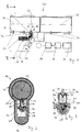
- FIGS. 1 to 5 An embodiment of a lock cylinder is in the FIGS. 1 to 5 represented and designated there by the reference numeral 10.
- the lock cylinder 10 includes a housing 12 having a substantially hollow cylindrical receptacle 14 for receiving a lock core 16.
- an additional lock core 18 is aligned with the lock core 16.
- the lock core 16 and / or the lock cores 16 and 18 are rotatable about a lock core axis 20 for actuating a lock bolt 22.
- the lock core 16 and / or the lock cores 16 and 18 can be locked to the housing 12 by means of a plurality of locking elements 24.
- the blocking elements 24 are made of their (in Fig. 1 shown) by means of an inserted into the lock core 16 key (not shown) spent in its release position to allow rotation of the lock cylinder 16 and / or the lock cylinder 16, 18 about the lock cylinder axis 20 within the housing 12.
- the lock cylinder 10 comprises a generally designated by the reference numeral 26 additional lock for locking at least one of the lock cores 16, 18 with the housing 12.
- the auxiliary lock 26 includes a motor drive 28 and a locking member 30.
- the locking member 30 is actuated independently of the locking elements 24 and serves as additional security.
- an electrical energy store in particular in the form of a battery 32, is provided.
- the battery 32 is preferably disposed within the housing 12 of the lock cylinder 10.
- the locking cylinder 10 comprises a transmitting / receiving unit 34, which cooperates with a user identification (not shown), for example a transponder.
- the transmitting / receiving unit 34 is coupled to an evaluation / control unit 36, which serves to control the motor drive 28.
- the transmitting / receiving unit 34 and the evaluation / control unit 36 are preferably arranged within the housing 12 of the lock cylinder 10.
- At least one of the parts battery 32, transmitting / receiving unit 34, evaluation / control unit 36, preferably all parts 32, 34, 36, are arranged outside the housing 12 of the lock cylinder 10, in particular on or a connected to the housing 12 component or on or in a housing 12 adjacent to the arranged component, such as a rosette.
- the lock core 16 has a cylindrical sliding surface 38 which, viewed in the circumferential direction of the outer surface of the lock core 16, is interrupted in the region of a locking element receptacle 40.
- the locking element receiving 40 is set back relative to the sliding surface 38 and relative to the lock core axis 20 in the radial direction.
- the position of the locking element 40 along the circumference of the sliding surface 38 is seen such that in a Release position of the lock core 16, in which a key in the lock core 16 can be inserted and executable from this, the locking element receptacle 40 is aligned with the locking element 30.
- the motor drive 28 is designed as a rotary drive and has an axis of rotation 42.
- the rotation axis 42 is connected to a drive part 44 (see FIG. Fig. 1 ), which carries a crank 46, which is arranged eccentrically offset relative to the axis of rotation 42.
- the crank 46 is integrally formed with the drive member 44, or the crank 46 is provided as a separate part and connected to the drive member 44.
- the crank 46 dips into a crank receptacle 48 of a Federab spalements designated overall by the reference numeral 50.
- the crank receptacle 48 is formed in the form of a backdrop.
- the spring support element 50 comprises a spring receiving space 52 for receiving a spring 54, which is designed in particular as a compression spring.
- the spring 54 cooperates with a first end 56 with the locking element 30 and with a second end 58 with a Federabstütz construction 60 of the Federab prolements 50th
- the locking element 30 has a shoulder 62 on which the first end 56 of the spring 54 is supported.
- the shoulder 62 also cooperates with a stop 64 of the Federab spalements 50, in such a way that a movement path of the locking member 30 is limited in the direction of the lock core axis 20.
- An effective axis 66 along which the spring 54 is compressible and can be relaxed, runs in the radial direction with respect to the lock core axis 20.
- the spring support element 50 is in parallel direction in a built-in housing 12 thrust bearing 68 out. In this way, the Federab 100 within the housing 12 along a parallel to the axis of action 66 of the spring 54 or identical thereto axis is displaceable.
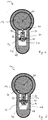
- auxiliary latch 26 The operation of the auxiliary latch 26 will be described below with reference to the FIGS. 2 to 5 described.
- the lock core 16 assumes its release position, so that the locking element receptacle 40 is aligned with the locking element 30 of the additional latch 26.
- the locking element 30 is immersed in the locking element receptacle 40 and prevents regardless of the position of the locking elements 24, a rotational movement of the lock core 16 within the housing 12.
- the spring 54 also assumes its locking position, in which the Federab nulement 50, the spring 54 towards the lock core 16th displaced as in a release position of the spring 54 and the locking element 30 (see. Fig. 4 ).
- the additional interlock 26 can be actuated, for example by recognizing an authorized user who carries a transponder with him and who cooperates with the transceiver 34 so that the evaluation / control unit 36 controls the motor drive 28, that this is rotated counterclockwise.
- This causes a rotation of the crank 46 about the rotation axis 42 in the counterclockwise direction and a displacement of Federab sublements 50 within the thrust bearing 68, so that the spring 54 assumes its release position, in which it is located further away from the lock core 16, as in the locking position according to FIGS. 2 and 3 ,
- the shoulder 62 of the locking element 30 cooperates with the stop 64 of the Federab spalements 50.
- the free end of the locking element 30 is disposed out of engagement with the locking element receptacle 40 of the lock core 16, so that the lock core 16 within the housing 12 is rotatable. This rotation takes place by means of an inserted into the lock core 16 key which actuates the locking elements 24, so that the locking elements 24 release the lock cylinder 16.
- the locking element 30 can not dip into the locking element receptacle 40, but to the sliding surface 38 of the lock core 16 is applied, the spring 54, which is clamped between the shoulder 62 of the locking element 30 and the Federabstweil Chemistry 60, compressed. In this way, the locking element 30 is biased in the direction of its locking position. As soon as the lock core 16 is rotated into its release rotational position, the locking element receptacle 40 comes into alignment with the locking element 30, which is then transferred by means of the compressed spring 54 from the prestressed state on the sliding surface 38 into the locking position (cf. Fig. 2 ).
- the lock cylinder according to the invention has the advantage that the lock core 16 with inserted key in the in Fig. 5 shown, deviating from a release rotational position rotational position may remain without a cyclic actuation of the additional lock 26 is required in this time.
- the transfer to the locking position is ensured by the bias of the spring 54.
- a spring 54 which is designed as a compression spring
Landscapes
- Physics & Mathematics (AREA)
- Electromagnetism (AREA)
- Lock And Its Accessories (AREA)
Description
- Die Erfindung betrifft einen Schließzylinder mit den Merkmalen des Oberbegriffs des Patentanspruchs 1, gemäß
JP 2004 324293 A - Aus der
EP 0 743 412 A1 ist ein Profilzylinder bekannt, mit einem von einem Antrieb verfahrbaren, zusätzlichen Sperrelement (nachfolgend Verriegelungselement), welches in einer Sperrstellung die Drehbeweglichkeit eines Schließkerns verhindert. Der Antrieb ist in Abhängigkeit einer beispielsweise auf dem Schlüssel abgelegten Benutzerkennung ansteuerbar. - Bei dem bekannten Profilzylinder ist eine Verriegelung des Schließkerns mittels des zusätzlichen Verriegelungselements nur in einer bestimmten Drehlage des Schließkerns möglich, nämlich in der Freigabedrehlage, in welcher der Schlüssel in den Schließkern einführbar und aus diesem ausführbar ist. Es ist aber möglich, dass ein solcher Profilzylinder mit eingestecktem Schlüssel längere Zeit in einer von der Freigabedrehlage abweichenden Drehlage verbleibt. In dieser Zeit führt ein zyklisches Ansteuern des zusätzlichen Verriegelungselements dazu, dass dieses nicht in seine Verriegelungsposition überführt werden kann, dabei aber jeder einzelne Ansteuerversuch mit einem erheblichen Energieverbrauch einhergeht. Dies ist insbesondere dann nachteilig, wenn der Antrieb des zusätzlichen Sperrelements batteriebetrieben ist.
- Weitere Schließzylinder sind aus der
FR 2 808 552 A1 JP H06 73930 A WO98/28508 A1 - Hiervon ausgehend besteht Bedarf, eine aus der
EP 0 743 412 A1 bekannte Anordnung so zu verbessern, dass sie auch für einen Batteriebetrieb gut geeignet ist. - Diese Aufgabe wird bei einem Schließzylinder der eingangs genannten Art erfindungsgemäß durch die kennzeichnenden Merkmale des Patentanspruchs 1 gelöst.
- Die Zusatzverriegelung umfasst eine Feder, welche nicht nur eine Verriegelungskraft für das Verriegelungselement bereitstellt, sondern mittels des motorischen Antriebs örtlich verlagerbar ist. Dies ermöglicht es in einer Freigabeposition der Feder, das Verriegelungselement in einem unverriegelten Zustand anzuordnen. In einer von der Freigabedrehlage des Schließkerns abweichenden Drehlage ermöglicht es die örtlich verlagerbare Feder, Energie zu speichern und das Verriegelungselement mit einer Vorspannung zu beaufschlagen. Diese gespeicherte Energie steht für eine Überführung des Verriegelungselements in die Verriegelungsposition zur Verfügung, unmittelbar nachdem der Schließkern in seine Freigabedrehlage überführt wurde.
- Der erfindungsgemäße Schließzylinder ermöglicht es, auf eine zyklische Abfrage des motorischen Antriebs zur Ansteuerung des Verriegelungselements verzichten zu können. Es genügt, dass der motorische Antrieb bei Erkennung eines berechtigten Nutzers die Feder in ihre Freigabeposition überführt und dass, beispielsweise nach Ablauf einer vorgebbaren Zeitdauer, die Feder in ihre Verriegelungsposition überführt wird. Bei Überführung der Feder in die Verriegelungsposition ist es unerheblich, ob sich der Schließzylinder bereits in der Freigabedrehlage befindet oder nicht. Sofern der Schließzylinder eine von der Freigabedrehlage abweichende Drehlage einnimmt, wird die für eine Überführung des Verriegelungselement in dessen Verriegelungsposition erforderliche Energie mittels der in ihrer Verriegelungsposition befindlichen Feder gespeichert. Diese Energie wird bei Überführung des Schließzylinders in die Freigabedrehlage genutzt, um das Verriegelungselement aus seiner vorgespannten Position heraus in die Verriegelungsposition zu überführen.
- Vorzugsweise ist das Verriegelungselement in Form eines Sperrstifts ausgebildet. Dies ermöglicht einen vergleichsweise kompakten und raumsparenden Aufbau einer Zusatzverriegelung.
- Ferner ist es bevorzugt, dass die Feder als Druckfeder ausgebildet ist. Auch dies trägt zu einem kompakten Aufbau der Zusatzverrieglung bei. Es ist aber auch denkbar, die Feder als Zugfeder auszubilden.
- Bevorzugt ist es ferner, wenn die Feder mit einem ersten Ende mit dem Verriegelungselement und mit einem zweiten Ende zumindest mittelbar mit dem motorischen Antrieb zusammenwirkt. Die Feder liegt also im Kraftfluss zwischen motorischem Antrieb und Verriegelungselement, sodass der motorische Antrieb unter Zwischenschaltung der Feder mittelbar auch auf das Verriegelungselement wirkt.
- Es ist denkbar, dass die Feder in ihrer Freigabeposition vollständig entspannt ist, jedoch so weit von dem Schließkern beabstandet, dass das Verriegelungselement nicht mit dem Schließkern verriegelt ist und eine Drehbewegung des Schließkerns erlaubt. Bevorzugt ist es jedoch, dass das Verriegelungselement in der Freigabeposition der Feder mit einem Anschlag zusammenwirkt, der eine Überführung des Verriegelungselements in dessen Verriegelungsposition verhindert. Auf diese Weise ist es möglich, dass auch in Freigabeposition der Feder eine Vorspannung auf das Verriegelungselement wirkt, sodass in der Verriegelungsposition der Feder eine vergleichsweise höhere, auf das Verriegelungselement wirkende Federkraft bereitstellbar ist. Dies trägt zu einer zuverlässigen Überführung des Verriegelungselements in dessen Verriegelungsposition bei.
- Bevorzugt ist es ferner, wenn in der Verriegelungsposition der Feder und in einer von der Freigabedrehlage des Schließkerns abweichenden Drehlage des Schließkerns das Verriegelungselement gegen eine Gleitfläche des Schließkerns vorgespannt ist. Bei der Gleitfläche handelt es sich insbesondere um die zylindrische Außenfläche des Schließkerns. Diese Außenfläche weist vorzugsweise eine Vertiefung auf, in welche das (vorgespannte) Verriegelungselement eintauchbar ist.
- Erfindungsgemäß ist vorgesehen, dass die Feder an einem Federabstützelement abgestützt ist. Dies ermöglicht eine einfache örtliche Verlagerung der Feder, insbesondere eines o.g. zweiten Endes der Feder.
- Erfindungsgemäß ist das Federabstützelement parallel zu oder entlang einer Wirkachse der Feder örtlich verlagerbar. Hierdurch kann eine zumindest weitestgehende querkraftfreie Anordnung geschaffen werden.
- Bevorzugt ist es ferner, dass die Wirkachse der Feder bezogen auf eine Drehachse des Schließkerns radial verläuft. Dies unterstützt eine zuverlässige Überführung des Verriegelungselements aus einer vorgespannten Position in die Verriegelungsposition hinein und zwar unabhängig davon, in welcher Drehrichtung der Schließkern in seine Freigabedrehlage gedreht wird.
- Bei einer bevorzugten Ausführungsform ist das Federabstützelement in einem Schublager geführt. Dies ermöglicht eine einfache und zuverlässige Verlagerung einer Abstützfläche des Federabstützelements.
- Ein besonders kompakter Aufbau ergibt sich, wenn das Schublager in das Gehäuse integriert ist.
- Vorzugsweise ist das Federabstützelement über ein Drehschublager mit dem motorischen Antrieb gekoppelt. Dies ermöglicht die Verwendung eines motorischen Drehantriebs. Es ist aber auch denkbar, einen Linearantrieb zu verwenden, welcher das Federabstützelement entlang einer geraden Achse verschiebt.
- Bei Verwendung eines Drehschublagers ist es insbesondere bevorzugt, wenn dieses eine, bezogen auf eine Drehachse des motorischen Antriebs exzentrische, in eine Drehrichtung antreibbare Kurbel umfasst, welche mit einer Kurbelaufnahme des Federabstützelements zusammenwirkt. Dies ermöglicht eine einfache Umsetzung einer Drehbewegung des motorischen Antriebs in eine geradlinige Bewegung des Federabstützelements.
- Besondere Vorteile ergeben sich, wenn der motorische Antrieb mittels einer Batterie mit Energie versorgt ist. In diesem Fall hat der Schließzylinder im Vergleich zu aus dem Stand der Technik bekannten Anordnungen eine erheblich verlängerte, wartungsfreie Betriebsdauer.
- Eine zyklische Betätigung des Verriegelungselements in einer Nichtfreigabedrehlage des Schließzylinders könnte gegebenenfalls auch dadurch verhindern werden, dass eine Einrichtung zur Erfassung der Drehlage des Schließkerns innerhalb des Gehäuses vorgesehen ist. Die vorliegende Erfindung ermöglicht es aber gerade, auf eine solche Einrichtung zu verzichten, welche bei einer bevorzugten Ausführungsform ausdrücklich nicht vorgesehen ist.
- Vorteile und Ausgestaltungen des erfindungsgemäßen Schließzylinders sowie weitere Merkmale und Vorteile der Erfindung sind Gegenstand der nachfolgenden Beschreibung und der zeichnerischen Darstellung einer bevorzugten Ausführungsform.
- In der Zeichnung zeigen:
- Fig. 1
- eine Seitenansicht einer Ausführungsform eines Schließzylinders;
- Fig. 2
- eine Vorderansicht des Schließzylinders entsprechend einer in
Fig. 1 mit II - II bezeichneten Sichtebene, wobei ein Schließkern eine Freigabedrehlage einnimmt und ein Verriegelungselement mit dem Schließkern verriegelt ist; - Fig. 3
- einen Ausschnitt aus
Fig. 2 in vergrößerter Darstellung; - Fig. 4
- eine der
Fig. 2 entsprechende Ansicht, wobei das Verriegelungselement unverriegelt ist und eine Drehung des Schließkerns erlaubt; und - Fig. 5
- eine der der
Fig. 2 entsprechende Ansicht, wobei der Schließkern eine von der Freigabedrehlage abweichende Drehlage einnimmt und das Verriegelungselement in Richtung seiner Verriegelungsposition vorgespannt ist. - Eine Ausführungsform eines Schließzylinders ist in den
Figuren 1 bis 5 dargestellt und dort insgesamt mit dem Bezugszeichen 10 bezeichnet. Der Schließzylinder 10 umfasst ein Gehäuse 12 mit einer im Wesentlichen hohlzylindrischen Aufnahme 14 zur Aufnahme eines Schließkerns 16. Bei dem in der Zeichnung dargestellten Ausführungsbeispiel ist ein mit dem Schließkern 16 fluchtender, zusätzlicher Schließkern 18 vorgesehen. Der Schließkern 16 und/oder die Schließkerne 16 und 18 sind um eine Schließkernachse 20 drehbar, zur Betätigung eines Schließbarts 22. - Der Schließkern 16 und/oder die Schließkerne 16 und 18 sind mittels einer Mehrzahl von Sperrelementen 24 mit dem Gehäuse 12 verriegelbar. Die Sperrelemente 24 werden aus ihrer (in
Fig. 1 dargestellten) Verriegelungsposition mittels eines in den Schließkern 16 eingeführten Schlüssels (nicht dargestellt) in ihre Freigabeposition verbracht, um eine Drehung des Schließzylinders 16 und/oder der Schließzylinder 16, 18 um die Schließzylinderachse 20 innerhalb des Gehäuses 12 zu ermöglichen. - Der Schließzylinder 10 umfasst eine insgesamt mit dem Bezugszeichen 26 bezeichnete Zusatzverriegelung zur Verriegelung zumindest eines der Schließkerne 16, 18 mit dem Gehäuse 12. Die Zusatzverriegelung 26 umfasst einen motorischen Antrieb 28 und ein Verriegelungselement 30. Das Verriegelungselement 30 ist unabhängig von den Sperrelementen 24 betätigbar und dient als Zusatzsicherung. Zur Energieversorgung des motorischen Antriebs 28 ist ein elektrischer Energiespeicher, insbesondere in Form einer Batterie 32, vorgesehen. Die Batterie 32 ist vorzugsweise innerhalb des Gehäuses 12 des Schließzylinders 10 angeordnet.
- Zur Steuerung der Zusatzverrieglung 26 umfasst der Schließzylinder 10 eine Sende-/Empfangseinheit 34, welche mit einer (nicht dargestellten) Benutzerkennung, beispielsweise einem Transponder, zusammenwirkt. Die Sende-/Empfangseinheit 34 ist mit einer Auswerte-/Steuereinheit 36 gekoppelt, welche zur Ansteuerung des motorischen Antriebs 28 dient. Die Sende-/Empfangseinheit 34 und die Auswerte-/Steuereinheit 36 sind vorzugsweise innerhalb des Gehäuses 12 des Schließzylinders 10 angeordnet.
- Bei einer alternativen Ausführungsform ist vorgesehen, dass zumindest eines der Teile Batterie 32, Sende-/Empfangseinheit 34, Auswerte-/Steuereinheit 36, vorzugsweise sämtliche Teile 32, 34, 36, außerhalb des Gehäuses 12 des Schließzylinders 10 angeordnet sind, insbesondere an oder einem mit dem Gehäuse 12 verbundenen Bauteil oder an oder in einem zu dem Gehäuse 12 benachbart angeordneten Bauteil, beispielsweise einer Rosette.
- Der Schließkern 16 weist eine zylindrische Gleitfläche 38 auf, welche in Umfangsrichtung der Außenfläche des Schließkerns 16 gesehen im Bereich einer Verriegelungselementaufnahme 40 unterbrochen ist. Die Verriegelungselementaufnahme 40 ist bezogen auf die Gleitfläche 38 und bezogen auf die Schließkernachse 20 in radialer Richtung zurückversetzt.
- Die Lage des Verriegelungselement 40 entlang des Umfangs der Gleitfläche 38 gesehen ist derart, dass in einer Freigabelage des Schließkerns 16, in welcher ein Schlüssel in den Schließkern 16 einführbar und aus diesem ausführbar ist, die Verriegelungselementaufnahme 40 mit dem Verriegelungselement 30 fluchtet.
- Der motorische Antrieb 28 ist als Drehantrieb ausgebildet und weist eine Drehachse 42 auf. Die Drehachse 42 ist mit einem Antriebsteil 44 (vgl.
Fig. 1 ) verbunden, das eine Kurbel 46 trägt, welche bezogen auf die Drehachse 42 exzentrisch versetzt angeordnet ist. Die Kurbel 46 ist mit dem Antriebsteil 44 einstückig ausgebildet, oder die Kurbel 46 ist als separates Teil bereitgestellt und mit dem Antriebsteil 44 verbunden. Die Kurbel 46 taucht in eine Kurbelaufnahme 48 eines insgesamt mit dem Bezugszeichen 50 bezeichneten Federabstützelements ein. Die Kurbelaufnahme 48 ist in Form einer Kulisse ausgebildet. - Das Federabstützelement 50 umfasst einen Federaufnahmeraum 52 zur Aufnahme einer Feder 54, welche insbesondere als Druckfeder ausgebildet ist. Die Feder 54 wirkt mit einem ersten Ende 56 mit dem Verriegelungselement 30 zusammen und mit einem zweiten Ende 58 mit einer Federabstützfläche 60 des Federabstützelements 50.
- Das Verriegelungselement 30 weist eine Schulter 62 auf, an welcher sich das erste Ende 56 der Feder 54 abstützt. Die Schulter 62 wirkt auch mit einem Anschlag 64 des Federabstützelements 50 zusammen, und zwar derart, dass ein Bewegungsweg des Verriegelungselements 30 in Richtung auf die Schließkernachse 20 begrenzt wird.
- Eine Wirkachse 66, entlang welcher die Feder 54 komprimier- und entspannbar ist, verläuft bezogen auf die Schließkernachse 20 in radialer Richtung. Das Federabstützelement 50 ist in hierzu paralleler Richtung in einem in das Gehäuse 12 integrierten Schublager 68 geführt. Auf diese Weise ist das Federabstützelement 50 innerhalb des Gehäuses 12 entlang einer zu der Wirkachse 66 der Feder 54 parallelen oder hierzu identischen Achse verschiebbar.
- Die Funktionsweise der Zusatzverriegelung 26 wird nachfolgend unter Bezugnahme auf die
Figuren 2 bis 5 beschrieben. - In dem in
Fig. 2 dargestellten Zustand nimmt der Schließkern 16 seine Freigabedrehlage ein, sodass die Verriegelungselementaufnahme 40 mit dem Verriegelungselement 30 der Zusatzverriegelung 26 fluchtet. Das Verriegelungselement 30 ist in die Verriegelungselementaufnahme 40 eingetaucht und verhindert unabhängig von der Stellung der Sperrelemente 24 eine Drehbewegung des Schließkerns 16 innerhalb des Gehäuses 12. Auch die Feder 54 nimmt ihre Verriegelungsposition ein, in welcher das Federabstützelement 50 die Feder 54 weiter in Richtung Schließkern 16 verlagert als in einer Freigabeposition der Feder 54 und des Verriegelungselements 30 (vgl.Fig. 4 ). - In dem in
Fig. 2 dargestellten Verriegelungszustand befindet sich die Zusatzverriegelung 26 in einer stabilen Sperrlage, in welcher die Kurbel 46 im Uhrzeigersinn gesehen leicht versetzt zu einem oberen Totpunkt angeordnet ist. - Ausgehend von dem Zustand gemäß
Figuren 2 und 3 kann die Zusatzverriegelung 26 betätigt werden, beispielsweise durch Erkennung eines berechtigten Benutzers, der einen Transponder mit sich trägt und der mit der Sende-/Empfangseinheit 34 zusammenwirkt, sodass die Auswerte-/Steuereinheit 36 den motorischen Antrieb 28 so ansteuert, dass dieser entgegen dem Uhrzeigersinn verdreht wird. Dies bewirkt eine Verdrehung der Kurbel 46 um die Drehachse 42 entgegen dem Uhrzeigersinn und eine Verlagerung des Federabstützelements 50 innerhalb des Schublagers 68, sodass die Feder 54 ihre Freigabeposition einnimmt, in welcher sie weiter vom Schließkern 16 entfernt angeordnet ist, als in der Verriegelungsposition gemäßFiguren 2 und 3 . In der Freigabeposition der Feder 54 wirkt die Schulter 62 des Verriegelungselements 30 mit dem Anschlag 64 des Federabstützelements 50 zusammen. Das freie Ende des Verriegelungselements 30 ist außerhalb eines Eingriffs mit der Verriegelungselementaufnahme 40 des Schließkerns 16 angeordnet, sodass der Schließkern 16 innerhalb des Gehäuses 12 verdrehbar ist. Diese Verdrehung erfolgt mittels eines in den Schließkern 16 eingeführten Schlüssels, welcher die Sperrelemente 24 betätigt, sodass auch die Sperrelemente 24 den Schließzylinder 16 freigeben. - Wenn ausgehend von dem in
Fig. 4 dargestellten Zustand des Schließzylinders 10 der Schließkern 16 verdreht wird, sodass die Verriegelungselementaufnahme 40 nicht mehr mit dem Verriegelungselement 30 fluchtet, kann das Verriegelungselement 30 nicht in die Verriegelungselementaufnahme 40 eingetaucht werden. Ausgehend von dem inFig. 4 dargestellten Zustand der Zusatzverriegelung 26 kann diese aber bereits in einen "Vorverriegelungszustand" zurücküberführt werden, nämlich indem der motorische Antrieb 28 im Uhrzeigersinn angetrieben wird, sodass die Kurbel 46 über die Kurbelaufnahme 48 das Federabstützelement 50 in Richtung auf den Schließkern 16 bewegt (vgl.Fig. 5 ). Auf diese Weise wird auch die Feder 54 aus der Freigabeposition gemäßFig. 4 in die Verriegelungsposition gemäßFig. 5 verbracht. Da das Verriegelungselement 30 nicht in die Verriegelungselementaufnahme 40 eintauchen kann, sondern an der Gleitfläche 38 des Schließkerns 16 anliegt, wird die Feder 54, welche zwischen der Schulter 62 des Verriegelungselements 30 und der Federabstützfläche 60 eingespannt ist, komprimiert. Auf diese Weise wird das Verriegelungselement 30 in Richtung seiner Verriegelungsposition vorgespannt. Sobald der Schließkern 16 in seine Freigabedrehlage verdreht wird, gelangt die Verriegelungselementaufnahme 40 in Flucht mit dem Verriegelungselement 30, welches dann mittels der komprimierten Feder 54 aus dem an der Gleitfläche 38 anliegenden, dort vorgespannten Zustand in die Verriegelungsposition überführt wird (vgl.Fig. 2 ). - Der erfindungsgemäße Schließzylinder hat den Vorteil, dass der Schließkern 16 mit eingestecktem Schlüssel in der in
Fig. 5 dargestellten, von einer Freigabedrehlage abweichenden Drehlage verbleiben kann, ohne dass in dieser Zeit eine zyklische Betätigung der Zusatzverriegelung 26 erforderlich ist. Die Überführung in die Verriegelungsposition ist durch die Vorspannung der Feder 54 sichergestellt. - Alternativ zu einer Feder 54, welche als Druckfeder ausgebildet ist, ist es auch denkbar, eine Blattfeder zu verwenden.
Claims (13)
- Schließzylinder (10) mit einem in einem Gehäuse (12) drehbaren Schließkern (16), wobei der Schließkern (16) mittels mindestens eines mit einem Schlüssel betätigbaren Sperrelements (24) mit dem Gehäuse (12) verriegelbar ist, wobei der Schlüssel in einer Freigabedrehlage des Schließkerns (16) in den Schließkern (16) einführbar und aus diesem ausführbar ist, wobei eine unabhängig von dem Sperrelement (24) und dem Schlüssel und mittels eines motorischen Antriebs (28) betätigbare Zusatzverriegelung (26) zur Verriegelung des Schließkerns (16) mit dem Gehäuse (12) vorgesehen ist, wobei die Zusatzverriegelung (26) ein Verriegelungselement (30) umfasst, welches in einer Verriegelungsposition eine Drehbewegung des Schließkerns (16) relativ zu dem Gehäuse (12) verhindert und in einer Freigabeposition eine Drehbewegung des Schließkerns (16) relativ zu dem Gehäuse (12) erlaubt, dadurch gekennzeichnet, dass die Zusatzverriegelung (26) eine mittels des motorischen Antriebs (28) örtlich verlagerbare und mit dem Verriegelungselement zusammenwirkende Feder (54) umfasst, wobei in einer Freigabeposition der Feder (54) das Verriegelungselement (30) nicht in dessen Verriegelungsposition überführbar ist und wobei in einer Verriegelungsposition der Feder (54) die Feder (54) das Verriegelungselement (30) mit einer Kraft beaufschlagt, welche das Verriegelungselement (30) in einer von der Freigabedrehlage des Schließkerns (16) abweichenden Drehlage in Richtung seiner Verriegelungsposition vorspannt und welche das Verriegelungselement (30) in der Freigabedrehlage des Schließkerns (16) in die Verriegelungsposition überführt, und dass die Feder (54) an einem Federabstützelement (50) abgestützt ist, welches parallel zu oder entlang einer Wirkachse (66) der Feder (54) örtlich verlagerbar ist.
- Schließzylinder (10) nach Anspruch 1, dadurch gekennzeichnet, dass das Verriegelungselement (30) in Form eines Sperrstifts ausgebildet ist.
- Schließzylinder (10) nach einem der voranstehenden Ansprüche, dadurch gekennzeichnet, dass die Feder (54) als Druckfeder ausgebildet ist.
- Schließzylinder (10) nach einem der voranstehenden Ansprüche, dadurch gekennzeichnet, dass die Feder (54) mit einem ersten Ende (56) mit dem Verriegelungselement (30) und mit einem zweiten Ende (58) zumindest mittelbar mit dem motorischen Antrieb (26) zusammenwirkt.
- Schließzylinder (10) nach einem der voranstehenden Ansprüche, dadurch gekennzeichnet, dass das Verriegelungselement (30) in der Freigabeposition der Feder (54) mit einem Anschlag (64) zusammenwirkt, der eine Überführung des Verriegelungselements (30) in dessen Verriegelungsposition verhindert.
- Schließzylinder (10) nach einem der voranstehenden Ansprüche, dadurch gekennzeichnet, dass in der Verriegelungsposition der Feder (54) und in einer von der Freigabedrehlage des Schließkerns (16) abweichenden Drehlage des Schließkerns (16) das Verriegelungselement (30) gegen eine Gleitfläche (38) des Schließkerns (16) vorgespannt ist.
- Schließzylinder (10) nach einem der voranstehenden Ansprüche, dadurch gekennzeichnet, dass die Wirkachse (66) der Feder (54) bezogen auf eine Drehachse (20) des Schließkerns (16) radial verläuft.
- Schließzylinder (10) nach einem einem der voranstehenden Ansprüche, dadurch gekennzeichnet, dass das Federabstützelement (50) in einem Schublager (68) geführt ist.
- Schließzylinder (10) nach Anspruch 8, dadurch gekennzeichnet, dass das Schublager (68) in das Gehäuse (12) integriert ist.
- Schließzylinder (10) nach einem der voranstehenden Ansprüche, dadurch gekennzeichnet, dass das Federabstützelement (50) über ein Drehschublager mit dem motorischen Antrieb (28) gekoppelt ist.
- Schließzylinder (10) nach Anspruch 10, dadurch gekennzeichnet, dass das Drehschublager eine bezogen auf eine Drehachse (42) des motorischen Antriebs (28) exzentrische, in einer Drehrichtung antreibbare Kurbel (46) umfasst, welche mit einer Kurbelaufnahme (48) des Federabstützelements (50) zusammenwirkt.
- Schließzylinder (10) nach einem der voranstehenden Ansprüche, dadurch gekennzeichnet, dass der motorische Antrieb (28) mittels einer Batterie (32) mit Energie versorgt ist.
- Schließzylinder (10) nach einem der voranstehenden Ansprüche, dadurch gekennzeichnet, dass der Schließzylinder (1) eine Einrichtung zur Erfassung der Drehlage des Schließkerns (16) innerhalb des Gehäuses (12) ausdrücklich nicht aufweist.
Priority Applications (2)
| Application Number | Priority Date | Filing Date | Title |
|---|---|---|---|
| EP13198456.9A EP2886756B1 (de) | 2013-12-19 | 2013-12-19 | Schliesszylinder |
| PL13198456T PL2886756T3 (pl) | 2013-12-19 | 2013-12-19 | Wkładka bębenkowa |
Applications Claiming Priority (1)
| Application Number | Priority Date | Filing Date | Title |
|---|---|---|---|
| EP13198456.9A EP2886756B1 (de) | 2013-12-19 | 2013-12-19 | Schliesszylinder |
Publications (2)
| Publication Number | Publication Date |
|---|---|
| EP2886756A1 EP2886756A1 (de) | 2015-06-24 |
| EP2886756B1 true EP2886756B1 (de) | 2019-02-06 |
Family
ID=49884999
Family Applications (1)
| Application Number | Title | Priority Date | Filing Date |
|---|---|---|---|
| EP13198456.9A Active EP2886756B1 (de) | 2013-12-19 | 2013-12-19 | Schliesszylinder |
Country Status (2)
| Country | Link |
|---|---|
| EP (1) | EP2886756B1 (de) |
| PL (1) | PL2886756T3 (de) |
Family Cites Families (6)
| Publication number | Priority date | Publication date | Assignee | Title |
|---|---|---|---|---|
| US4798068A (en) * | 1986-11-27 | 1989-01-17 | Kokusai Gijutsu Kaihatsu Kabushiki Kaisha | Electrically controlled type cylinder for locks |
| JPH0673930A (ja) * | 1992-08-11 | 1994-03-15 | Kokusai Gijutsu Kaihatsu Kk | シリンダ錠 |
| DE19517704C2 (de) | 1995-05-13 | 1999-01-21 | Bks Gmbh | Profilzylinder |
| ES2159152T3 (es) * | 1996-12-24 | 2001-09-16 | Kaba Schliesssysteme Ag | Dispositivo de bloqueo. |
| FR2808552B1 (fr) * | 2000-05-04 | 2003-06-13 | Vachette Sa | Serrure a deverrouillage mecanique et electrique |
| JP4117705B2 (ja) * | 2003-04-25 | 2008-07-16 | 株式会社アルファ | シリンダ錠 |
-
2013
- 2013-12-19 EP EP13198456.9A patent/EP2886756B1/de active Active
- 2013-12-19 PL PL13198456T patent/PL2886756T3/pl unknown
Non-Patent Citations (1)
| Title |
|---|
| None * |
Also Published As
| Publication number | Publication date |
|---|---|
| EP2886756A1 (de) | 2015-06-24 |
| PL2886756T3 (pl) | 2019-07-31 |
Similar Documents
| Publication | Publication Date | Title |
|---|---|---|
| EP1636454B1 (de) | Elektromechanischer schliesszylinder | |
| DE102007005214B3 (de) | Elektromechanisches Schließsystem | |
| EP3153648B1 (de) | Hangschloss | |
| DE102010018243B4 (de) | Schließzylinderanordnung | |
| EP1736620A1 (de) | Schliesszylinder mit gesperrter Knaufwelle | |
| WO2012072066A2 (de) | Bewegungssperre für ein sperrelement oder einen aktuator in einem schliesssystem | |
| DE102007011554B4 (de) | Koppeleinheit für elektronische Schließ-Systeme | |
| DE102015108664A1 (de) | Schließzylinder mit Rückstellsperre | |
| EP3243980B1 (de) | Verriegelungssystem | |
| EP2314900B1 (de) | Ventileinrichtung | |
| DE10359620A1 (de) | Sicherheitsschloss mit mechanischer und elektrischer Verriegelung | |
| DE602004003658T2 (de) | Schlüssel zur Betätigung eines Schlosses | |
| DE10334335B4 (de) | Elektronisches Lenkschloß und elektronischer Zündanlaßschalter für Kraftfahrzeuge | |
| DE10301998B4 (de) | Schließhilfe zum Verschließen einer mit einem Türschloß versehenen Fahrzeugtür | |
| EP2886756B1 (de) | Schliesszylinder | |
| EP1712713B1 (de) | Schliessvorrichtung | |
| AT508868B1 (de) | Zylinderschloss | |
| DE2617798A1 (de) | Schloss mit drehbarem zylinderkern | |
| EP3070236B1 (de) | Notentriegelungsvorrichtung | |
| EP2765260B1 (de) | Schliesszylinder | |
| EP1182103B1 (de) | Vorrichtung zur Verriegelung der Lenkspindel eines Kraftfahrzeuges | |
| EP3502380B1 (de) | Türdrückerbefestigungsvorrichtung | |
| CH661961A5 (de) | Magnetschloss. | |
| EP0663498A1 (de) | Schliesszylinder | |
| DE2549774A1 (de) | Lenk- und zuendschloss |
Legal Events
| Date | Code | Title | Description |
|---|---|---|---|
| PUAI | Public reference made under article 153(3) epc to a published international application that has entered the european phase |
Free format text: ORIGINAL CODE: 0009012 |
|
| 17P | Request for examination filed |
Effective date: 20131219 |
|
| AK | Designated contracting states |
Kind code of ref document: A1 Designated state(s): AL AT BE BG CH CY CZ DE DK EE ES FI FR GB GR HR HU IE IS IT LI LT LU LV MC MK MT NL NO PL PT RO RS SE SI SK SM TR |
|
| AX | Request for extension of the european patent |
Extension state: BA ME |
|
| R17P | Request for examination filed (corrected) |
Effective date: 20151209 |
|
| RBV | Designated contracting states (corrected) |
Designated state(s): AL AT BE BG CH CY CZ DE DK EE ES FI FR GB GR HR HU IE IS IT LI LT LU LV MC MK MT NL NO PL PT RO RS SE SI SK SM TR |
|
| GRAP | Despatch of communication of intention to grant a patent |
Free format text: ORIGINAL CODE: EPIDOSNIGR1 |
|
| STAA | Information on the status of an ep patent application or granted ep patent |
Free format text: STATUS: GRANT OF PATENT IS INTENDED |
|
| RIC1 | Information provided on ipc code assigned before grant |
Ipc: E05B 47/06 20060101AFI20180328BHEP Ipc: E05B 47/00 20060101ALI20180328BHEP |
|
| INTG | Intention to grant announced |
Effective date: 20180417 |
|
| GRAJ | Information related to disapproval of communication of intention to grant by the applicant or resumption of examination proceedings by the epo deleted |
Free format text: ORIGINAL CODE: EPIDOSDIGR1 |
|
| GRAP | Despatch of communication of intention to grant a patent |
Free format text: ORIGINAL CODE: EPIDOSNIGR1 |
|
| INTG | Intention to grant announced |
Effective date: 20180614 |
|
| GRAJ | Information related to disapproval of communication of intention to grant by the applicant or resumption of examination proceedings by the epo deleted |
Free format text: ORIGINAL CODE: EPIDOSDIGR1 |
|
| STAA | Information on the status of an ep patent application or granted ep patent |
Free format text: STATUS: REQUEST FOR EXAMINATION WAS MADE |
|
| INTG | Intention to grant announced |
Effective date: 20180628 |
|
| GRAP | Despatch of communication of intention to grant a patent |
Free format text: ORIGINAL CODE: EPIDOSNIGR1 |
|
| STAA | Information on the status of an ep patent application or granted ep patent |
Free format text: STATUS: GRANT OF PATENT IS INTENDED |
|
| INTC | Intention to grant announced (deleted) | ||
| INTG | Intention to grant announced |
Effective date: 20180822 |
|
| GRAS | Grant fee paid |
Free format text: ORIGINAL CODE: EPIDOSNIGR3 |
|
| GRAA | (expected) grant |
Free format text: ORIGINAL CODE: 0009210 |
|
| STAA | Information on the status of an ep patent application or granted ep patent |
Free format text: STATUS: THE PATENT HAS BEEN GRANTED |
|
| AK | Designated contracting states |
Kind code of ref document: B1 Designated state(s): AL AT BE BG CH CY CZ DE DK EE ES FI FR GB GR HR HU IE IS IT LI LT LU LV MC MK MT NL NO PL PT RO RS SE SI SK SM TR |
|
| REG | Reference to a national code |
Ref country code: GB Ref legal event code: FG4D Free format text: NOT ENGLISH |
|
| REG | Reference to a national code |
Ref country code: CH Ref legal event code: EP Ref country code: AT Ref legal event code: REF Ref document number: 1095005 Country of ref document: AT Kind code of ref document: T Effective date: 20190215 |
|
| REG | Reference to a national code |
Ref country code: DE Ref legal event code: R096 Ref document number: 502013012141 Country of ref document: DE |
|
| REG | Reference to a national code |
Ref country code: IE Ref legal event code: FG4D Free format text: LANGUAGE OF EP DOCUMENT: GERMAN |
|
| REG | Reference to a national code |
Ref country code: NL Ref legal event code: FP |
|
| REG | Reference to a national code |
Ref country code: LT Ref legal event code: MG4D |
|
| PG25 | Lapsed in a contracting state [announced via postgrant information from national office to epo] |
Ref country code: FI Free format text: LAPSE BECAUSE OF FAILURE TO SUBMIT A TRANSLATION OF THE DESCRIPTION OR TO PAY THE FEE WITHIN THE PRESCRIBED TIME-LIMIT Effective date: 20190206 Ref country code: NO Free format text: LAPSE BECAUSE OF FAILURE TO SUBMIT A TRANSLATION OF THE DESCRIPTION OR TO PAY THE FEE WITHIN THE PRESCRIBED TIME-LIMIT Effective date: 20190506 Ref country code: SE Free format text: LAPSE BECAUSE OF FAILURE TO SUBMIT A TRANSLATION OF THE DESCRIPTION OR TO PAY THE FEE WITHIN THE PRESCRIBED TIME-LIMIT Effective date: 20190206 Ref country code: PT Free format text: LAPSE BECAUSE OF FAILURE TO SUBMIT A TRANSLATION OF THE DESCRIPTION OR TO PAY THE FEE WITHIN THE PRESCRIBED TIME-LIMIT Effective date: 20190606 Ref country code: LT Free format text: LAPSE BECAUSE OF FAILURE TO SUBMIT A TRANSLATION OF THE DESCRIPTION OR TO PAY THE FEE WITHIN THE PRESCRIBED TIME-LIMIT Effective date: 20190206 |
|
| PG25 | Lapsed in a contracting state [announced via postgrant information from national office to epo] |
Ref country code: RS Free format text: LAPSE BECAUSE OF FAILURE TO SUBMIT A TRANSLATION OF THE DESCRIPTION OR TO PAY THE FEE WITHIN THE PRESCRIBED TIME-LIMIT Effective date: 20190206 Ref country code: LV Free format text: LAPSE BECAUSE OF FAILURE TO SUBMIT A TRANSLATION OF THE DESCRIPTION OR TO PAY THE FEE WITHIN THE PRESCRIBED TIME-LIMIT Effective date: 20190206 Ref country code: BG Free format text: LAPSE BECAUSE OF FAILURE TO SUBMIT A TRANSLATION OF THE DESCRIPTION OR TO PAY THE FEE WITHIN THE PRESCRIBED TIME-LIMIT Effective date: 20190506 Ref country code: IS Free format text: LAPSE BECAUSE OF FAILURE TO SUBMIT A TRANSLATION OF THE DESCRIPTION OR TO PAY THE FEE WITHIN THE PRESCRIBED TIME-LIMIT Effective date: 20190606 Ref country code: GR Free format text: LAPSE BECAUSE OF FAILURE TO SUBMIT A TRANSLATION OF THE DESCRIPTION OR TO PAY THE FEE WITHIN THE PRESCRIBED TIME-LIMIT Effective date: 20190507 Ref country code: HR Free format text: LAPSE BECAUSE OF FAILURE TO SUBMIT A TRANSLATION OF THE DESCRIPTION OR TO PAY THE FEE WITHIN THE PRESCRIBED TIME-LIMIT Effective date: 20190206 |
|
| PG25 | Lapsed in a contracting state [announced via postgrant information from national office to epo] |
Ref country code: DK Free format text: LAPSE BECAUSE OF FAILURE TO SUBMIT A TRANSLATION OF THE DESCRIPTION OR TO PAY THE FEE WITHIN THE PRESCRIBED TIME-LIMIT Effective date: 20190206 Ref country code: EE Free format text: LAPSE BECAUSE OF FAILURE TO SUBMIT A TRANSLATION OF THE DESCRIPTION OR TO PAY THE FEE WITHIN THE PRESCRIBED TIME-LIMIT Effective date: 20190206 Ref country code: SK Free format text: LAPSE BECAUSE OF FAILURE TO SUBMIT A TRANSLATION OF THE DESCRIPTION OR TO PAY THE FEE WITHIN THE PRESCRIBED TIME-LIMIT Effective date: 20190206 Ref country code: AL Free format text: LAPSE BECAUSE OF FAILURE TO SUBMIT A TRANSLATION OF THE DESCRIPTION OR TO PAY THE FEE WITHIN THE PRESCRIBED TIME-LIMIT Effective date: 20190206 Ref country code: IT Free format text: LAPSE BECAUSE OF FAILURE TO SUBMIT A TRANSLATION OF THE DESCRIPTION OR TO PAY THE FEE WITHIN THE PRESCRIBED TIME-LIMIT Effective date: 20190206 Ref country code: ES Free format text: LAPSE BECAUSE OF FAILURE TO SUBMIT A TRANSLATION OF THE DESCRIPTION OR TO PAY THE FEE WITHIN THE PRESCRIBED TIME-LIMIT Effective date: 20190206 Ref country code: RO Free format text: LAPSE BECAUSE OF FAILURE TO SUBMIT A TRANSLATION OF THE DESCRIPTION OR TO PAY THE FEE WITHIN THE PRESCRIBED TIME-LIMIT Effective date: 20190206 Ref country code: CZ Free format text: LAPSE BECAUSE OF FAILURE TO SUBMIT A TRANSLATION OF THE DESCRIPTION OR TO PAY THE FEE WITHIN THE PRESCRIBED TIME-LIMIT Effective date: 20190206 |
|
| REG | Reference to a national code |
Ref country code: DE Ref legal event code: R097 Ref document number: 502013012141 Country of ref document: DE |
|
| PG25 | Lapsed in a contracting state [announced via postgrant information from national office to epo] |
Ref country code: SM Free format text: LAPSE BECAUSE OF FAILURE TO SUBMIT A TRANSLATION OF THE DESCRIPTION OR TO PAY THE FEE WITHIN THE PRESCRIBED TIME-LIMIT Effective date: 20190206 |
|
| PLBE | No opposition filed within time limit |
Free format text: ORIGINAL CODE: 0009261 |
|
| STAA | Information on the status of an ep patent application or granted ep patent |
Free format text: STATUS: NO OPPOSITION FILED WITHIN TIME LIMIT |
|
| 26N | No opposition filed |
Effective date: 20191107 |
|
| PG25 | Lapsed in a contracting state [announced via postgrant information from national office to epo] |
Ref country code: SI Free format text: LAPSE BECAUSE OF FAILURE TO SUBMIT A TRANSLATION OF THE DESCRIPTION OR TO PAY THE FEE WITHIN THE PRESCRIBED TIME-LIMIT Effective date: 20190206 |
|
| PG25 | Lapsed in a contracting state [announced via postgrant information from national office to epo] |
Ref country code: TR Free format text: LAPSE BECAUSE OF FAILURE TO SUBMIT A TRANSLATION OF THE DESCRIPTION OR TO PAY THE FEE WITHIN THE PRESCRIBED TIME-LIMIT Effective date: 20190206 |
|
| REG | Reference to a national code |
Ref country code: DE Ref legal event code: R082 Ref document number: 502013012141 Country of ref document: DE |
|
| REG | Reference to a national code |
Ref country code: CH Ref legal event code: PL |
|
| PG25 | Lapsed in a contracting state [announced via postgrant information from national office to epo] |
Ref country code: MC Free format text: LAPSE BECAUSE OF FAILURE TO SUBMIT A TRANSLATION OF THE DESCRIPTION OR TO PAY THE FEE WITHIN THE PRESCRIBED TIME-LIMIT Effective date: 20190206 |
|
| GBPC | Gb: european patent ceased through non-payment of renewal fee |
Effective date: 20191219 |
|
| PG25 | Lapsed in a contracting state [announced via postgrant information from national office to epo] |
Ref country code: IE Free format text: LAPSE BECAUSE OF NON-PAYMENT OF DUE FEES Effective date: 20191219 Ref country code: LU Free format text: LAPSE BECAUSE OF NON-PAYMENT OF DUE FEES Effective date: 20191219 Ref country code: GB Free format text: LAPSE BECAUSE OF NON-PAYMENT OF DUE FEES Effective date: 20191219 |
|
| PG25 | Lapsed in a contracting state [announced via postgrant information from national office to epo] |
Ref country code: CH Free format text: LAPSE BECAUSE OF NON-PAYMENT OF DUE FEES Effective date: 20191231 Ref country code: LI Free format text: LAPSE BECAUSE OF NON-PAYMENT OF DUE FEES Effective date: 20191231 |
|
| PG25 | Lapsed in a contracting state [announced via postgrant information from national office to epo] |
Ref country code: CY Free format text: LAPSE BECAUSE OF FAILURE TO SUBMIT A TRANSLATION OF THE DESCRIPTION OR TO PAY THE FEE WITHIN THE PRESCRIBED TIME-LIMIT Effective date: 20190206 |
|
| PG25 | Lapsed in a contracting state [announced via postgrant information from national office to epo] |
Ref country code: MT Free format text: LAPSE BECAUSE OF FAILURE TO SUBMIT A TRANSLATION OF THE DESCRIPTION OR TO PAY THE FEE WITHIN THE PRESCRIBED TIME-LIMIT Effective date: 20190206 Ref country code: HU Free format text: LAPSE BECAUSE OF FAILURE TO SUBMIT A TRANSLATION OF THE DESCRIPTION OR TO PAY THE FEE WITHIN THE PRESCRIBED TIME-LIMIT; INVALID AB INITIO Effective date: 20131219 |
|
| PG25 | Lapsed in a contracting state [announced via postgrant information from national office to epo] |
Ref country code: MK Free format text: LAPSE BECAUSE OF FAILURE TO SUBMIT A TRANSLATION OF THE DESCRIPTION OR TO PAY THE FEE WITHIN THE PRESCRIBED TIME-LIMIT Effective date: 20190206 |
|
| P01 | Opt-out of the competence of the unified patent court (upc) registered |
Effective date: 20230509 |
|
| PGFP | Annual fee paid to national office [announced via postgrant information from national office to epo] |
Ref country code: NL Payment date: 20231220 Year of fee payment: 11 Ref country code: FR Payment date: 20231221 Year of fee payment: 11 Ref country code: DE Payment date: 20231214 Year of fee payment: 11 Ref country code: AT Payment date: 20231221 Year of fee payment: 11 |
|
| PGFP | Annual fee paid to national office [announced via postgrant information from national office to epo] |
Ref country code: PL Payment date: 20231120 Year of fee payment: 11 Ref country code: BE Payment date: 20231220 Year of fee payment: 11 |