EP3448703B1 - Elektroauto - Google Patents
Elektroauto Download PDFInfo
- Publication number
- EP3448703B1 EP3448703B1 EP18729084.6A EP18729084A EP3448703B1 EP 3448703 B1 EP3448703 B1 EP 3448703B1 EP 18729084 A EP18729084 A EP 18729084A EP 3448703 B1 EP3448703 B1 EP 3448703B1
- Authority
- EP
- European Patent Office
- Prior art keywords
- electric motor
- electric
- rotor
- battery
- motor
- Prior art date
- Legal status (The legal status is an assumption and is not a legal conclusion. Google has not performed a legal analysis and makes no representation as to the accuracy of the status listed.)
- Active
Links
Images




Classifications
-
- B—PERFORMING OPERATIONS; TRANSPORTING
- B60—VEHICLES IN GENERAL
- B60K—ARRANGEMENT OR MOUNTING OF PROPULSION UNITS OR OF TRANSMISSIONS IN VEHICLES; ARRANGEMENT OR MOUNTING OF PLURAL DIVERSE PRIME-MOVERS IN VEHICLES; AUXILIARY DRIVES FOR VEHICLES; INSTRUMENTATION OR DASHBOARDS FOR VEHICLES; ARRANGEMENTS IN CONNECTION WITH COOLING, AIR INTAKE, GAS EXHAUST OR FUEL SUPPLY OF PROPULSION UNITS IN VEHICLES
- B60K1/00—Arrangement or mounting of electrical propulsion units
- B60K1/04—Arrangement or mounting of electrical propulsion units of the electric storage means for propulsion
-
- B—PERFORMING OPERATIONS; TRANSPORTING
- B60—VEHICLES IN GENERAL
- B60K—ARRANGEMENT OR MOUNTING OF PROPULSION UNITS OR OF TRANSMISSIONS IN VEHICLES; ARRANGEMENT OR MOUNTING OF PLURAL DIVERSE PRIME-MOVERS IN VEHICLES; AUXILIARY DRIVES FOR VEHICLES; INSTRUMENTATION OR DASHBOARDS FOR VEHICLES; ARRANGEMENTS IN CONNECTION WITH COOLING, AIR INTAKE, GAS EXHAUST OR FUEL SUPPLY OF PROPULSION UNITS IN VEHICLES
- B60K1/00—Arrangement or mounting of electrical propulsion units
- B60K1/02—Arrangement or mounting of electrical propulsion units comprising more than one electric motor
-
- B—PERFORMING OPERATIONS; TRANSPORTING
- B60—VEHICLES IN GENERAL
- B60K—ARRANGEMENT OR MOUNTING OF PROPULSION UNITS OR OF TRANSMISSIONS IN VEHICLES; ARRANGEMENT OR MOUNTING OF PLURAL DIVERSE PRIME-MOVERS IN VEHICLES; AUXILIARY DRIVES FOR VEHICLES; INSTRUMENTATION OR DASHBOARDS FOR VEHICLES; ARRANGEMENTS IN CONNECTION WITH COOLING, AIR INTAKE, GAS EXHAUST OR FUEL SUPPLY OF PROPULSION UNITS IN VEHICLES
- B60K1/00—Arrangement or mounting of electrical propulsion units
-
- B—PERFORMING OPERATIONS; TRANSPORTING
- B60—VEHICLES IN GENERAL
- B60K—ARRANGEMENT OR MOUNTING OF PROPULSION UNITS OR OF TRANSMISSIONS IN VEHICLES; ARRANGEMENT OR MOUNTING OF PLURAL DIVERSE PRIME-MOVERS IN VEHICLES; AUXILIARY DRIVES FOR VEHICLES; INSTRUMENTATION OR DASHBOARDS FOR VEHICLES; ARRANGEMENTS IN CONNECTION WITH COOLING, AIR INTAKE, GAS EXHAUST OR FUEL SUPPLY OF PROPULSION UNITS IN VEHICLES
- B60K7/00—Disposition of motor in, or adjacent to, traction wheel
- B60K7/0007—Disposition of motor in, or adjacent to, traction wheel the motor being electric
-
- F—MECHANICAL ENGINEERING; LIGHTING; HEATING; WEAPONS; BLASTING
- F16—ENGINEERING ELEMENTS AND UNITS; GENERAL MEASURES FOR PRODUCING AND MAINTAINING EFFECTIVE FUNCTIONING OF MACHINES OR INSTALLATIONS; THERMAL INSULATION IN GENERAL
- F16H—GEARING
- F16H57/00—General details of gearing
- F16H57/02—Gearboxes; Mounting gearing therein
- F16H57/037—Gearboxes for accommodating differential gearings
-
- B—PERFORMING OPERATIONS; TRANSPORTING
- B60—VEHICLES IN GENERAL
- B60K—ARRANGEMENT OR MOUNTING OF PROPULSION UNITS OR OF TRANSMISSIONS IN VEHICLES; ARRANGEMENT OR MOUNTING OF PLURAL DIVERSE PRIME-MOVERS IN VEHICLES; AUXILIARY DRIVES FOR VEHICLES; INSTRUMENTATION OR DASHBOARDS FOR VEHICLES; ARRANGEMENTS IN CONNECTION WITH COOLING, AIR INTAKE, GAS EXHAUST OR FUEL SUPPLY OF PROPULSION UNITS IN VEHICLES
- B60K1/00—Arrangement or mounting of electrical propulsion units
- B60K2001/001—Arrangement or mounting of electrical propulsion units one motor mounted on a propulsion axle for rotating right and left wheels of this axle
-
- B—PERFORMING OPERATIONS; TRANSPORTING
- B60—VEHICLES IN GENERAL
- B60K—ARRANGEMENT OR MOUNTING OF PROPULSION UNITS OR OF TRANSMISSIONS IN VEHICLES; ARRANGEMENT OR MOUNTING OF PLURAL DIVERSE PRIME-MOVERS IN VEHICLES; AUXILIARY DRIVES FOR VEHICLES; INSTRUMENTATION OR DASHBOARDS FOR VEHICLES; ARRANGEMENTS IN CONNECTION WITH COOLING, AIR INTAKE, GAS EXHAUST OR FUEL SUPPLY OF PROPULSION UNITS IN VEHICLES
- B60K1/00—Arrangement or mounting of electrical propulsion units
- B60K1/04—Arrangement or mounting of electrical propulsion units of the electric storage means for propulsion
- B60K2001/0405—Arrangement or mounting of electrical propulsion units of the electric storage means for propulsion characterised by their position
-
- B—PERFORMING OPERATIONS; TRANSPORTING
- B60—VEHICLES IN GENERAL
- B60K—ARRANGEMENT OR MOUNTING OF PROPULSION UNITS OR OF TRANSMISSIONS IN VEHICLES; ARRANGEMENT OR MOUNTING OF PLURAL DIVERSE PRIME-MOVERS IN VEHICLES; AUXILIARY DRIVES FOR VEHICLES; INSTRUMENTATION OR DASHBOARDS FOR VEHICLES; ARRANGEMENTS IN CONNECTION WITH COOLING, AIR INTAKE, GAS EXHAUST OR FUEL SUPPLY OF PROPULSION UNITS IN VEHICLES
- B60K1/00—Arrangement or mounting of electrical propulsion units
- B60K1/04—Arrangement or mounting of electrical propulsion units of the electric storage means for propulsion
- B60K2001/0405—Arrangement or mounting of electrical propulsion units of the electric storage means for propulsion characterised by their position
- B60K2001/0433—Arrangement under the rear seats
-
- B—PERFORMING OPERATIONS; TRANSPORTING
- B60—VEHICLES IN GENERAL
- B60K—ARRANGEMENT OR MOUNTING OF PROPULSION UNITS OR OF TRANSMISSIONS IN VEHICLES; ARRANGEMENT OR MOUNTING OF PLURAL DIVERSE PRIME-MOVERS IN VEHICLES; AUXILIARY DRIVES FOR VEHICLES; INSTRUMENTATION OR DASHBOARDS FOR VEHICLES; ARRANGEMENTS IN CONNECTION WITH COOLING, AIR INTAKE, GAS EXHAUST OR FUEL SUPPLY OF PROPULSION UNITS IN VEHICLES
- B60K1/00—Arrangement or mounting of electrical propulsion units
- B60K1/04—Arrangement or mounting of electrical propulsion units of the electric storage means for propulsion
- B60K2001/0405—Arrangement or mounting of electrical propulsion units of the electric storage means for propulsion characterised by their position
- B60K2001/0438—Arrangement under the floor
-
- B—PERFORMING OPERATIONS; TRANSPORTING
- B60—VEHICLES IN GENERAL
- B60K—ARRANGEMENT OR MOUNTING OF PROPULSION UNITS OR OF TRANSMISSIONS IN VEHICLES; ARRANGEMENT OR MOUNTING OF PLURAL DIVERSE PRIME-MOVERS IN VEHICLES; AUXILIARY DRIVES FOR VEHICLES; INSTRUMENTATION OR DASHBOARDS FOR VEHICLES; ARRANGEMENTS IN CONNECTION WITH COOLING, AIR INTAKE, GAS EXHAUST OR FUEL SUPPLY OF PROPULSION UNITS IN VEHICLES
- B60K7/00—Disposition of motor in, or adjacent to, traction wheel
- B60K2007/0069—Disposition of motor in, or adjacent to, traction wheel the motor axle being perpendicular to the wheel axle
- B60K2007/0076—Disposition of motor in, or adjacent to, traction wheel the motor axle being perpendicular to the wheel axle the motor axle being horizontal
-
- B—PERFORMING OPERATIONS; TRANSPORTING
- B60—VEHICLES IN GENERAL
- B60Y—INDEXING SCHEME RELATING TO ASPECTS CROSS-CUTTING VEHICLE TECHNOLOGY
- B60Y2200/00—Type of vehicle
- B60Y2200/90—Vehicles comprising electric prime movers
- B60Y2200/91—Electric vehicles
-
- B—PERFORMING OPERATIONS; TRANSPORTING
- B60—VEHICLES IN GENERAL
- B60Y—INDEXING SCHEME RELATING TO ASPECTS CROSS-CUTTING VEHICLE TECHNOLOGY
- B60Y2400/00—Special features of vehicle units
- B60Y2400/11—Electric energy storages
- B60Y2400/112—Batteries
-
- B—PERFORMING OPERATIONS; TRANSPORTING
- B60—VEHICLES IN GENERAL
- B60Y—INDEXING SCHEME RELATING TO ASPECTS CROSS-CUTTING VEHICLE TECHNOLOGY
- B60Y2400/00—Special features of vehicle units
- B60Y2400/60—Electric Machines, e.g. motors or generators
-
- Y—GENERAL TAGGING OF NEW TECHNOLOGICAL DEVELOPMENTS; GENERAL TAGGING OF CROSS-SECTIONAL TECHNOLOGIES SPANNING OVER SEVERAL SECTIONS OF THE IPC; TECHNICAL SUBJECTS COVERED BY FORMER USPC CROSS-REFERENCE ART COLLECTIONS [XRACs] AND DIGESTS
- Y02—TECHNOLOGIES OR APPLICATIONS FOR MITIGATION OR ADAPTATION AGAINST CLIMATE CHANGE
- Y02T—CLIMATE CHANGE MITIGATION TECHNOLOGIES RELATED TO TRANSPORTATION
- Y02T10/00—Road transport of goods or passengers
- Y02T10/60—Other road transportation technologies with climate change mitigation effect
- Y02T10/70—Energy storage systems for electromobility, e.g. batteries
Definitions
- the invention relates to an electric car according to the preamble of claim 1.
- Electric vehicles have been manufactured for some time and are experiencing a renaissance. In comparison to vehicles with internal combustion engines, however, their share has so far been low. Even if the manufacture of electric vehicles is fundamentally simpler and less expensive than the manufacture of internal combustion engine vehicles, electric motors of different sizes have been used for the different performance classes in the outer dimensions.
- the DE 10 2011 053 254 A1 describes a modular system for a modular electric vehicle, in which the battery runs again along the center tunnel.
- the axes of rotation of the electric motors run transversely to the longitudinal axis of the vehicle.
- the modularization of the electric motor drive has narrow limits.
- the requirements for an electric vehicle are that it can be modularized as far as possible with regard to its drive, so that several motorizations can be offered with little effort.
- the electric motors must have a particularly high torque with the most compact possible external dimensions. So far, it has not been possible to implement these requirements.
- the invention has for its object to propose an improved electric vehicle.
- the invention solves the problem by an electric car with the features of claim 1.
- the advantage of this electric car is that the electric motor and the battery are arranged at the same height and leads to the fact that the overall height that must be provided for the electric motor and the battery can be chosen to be small. It is particularly advantageous if, which is also a preferred embodiment, both the batteries and the electric motor are arranged below a level at which the driver's seat is located. In other words, the engine and battery are then completely located under the driver's seat. As a result, the center of gravity of the electric car is so low that good road holding results.
- this adaptation of the heights enables modularization of batteries and electric motor. This in turn makes it possible to efficiently plan and manufacture the production of different models with different drive powers.
- the electric car preferably has four wheels.
- the axis is the component to which the wheels are attached.
- the mathematical axis around which the wheels rotate is called the axis of rotation.
- the height of the electric motor is calculated in particular on the basis of the imaginary cuboid of minimum volume which contains 90% of the mass of the electric motor. In other words, it is possible that smaller areas of the electric motor protrude or form projections, although this is often not advantageous.
- the battery height is calculated in the same way.
- the feature that the electric motor and the battery are arranged at the same height means in particular that a vertical distance between the center of gravity of the battery and the center of gravity of the electric motor is at most a quarter, in particular at most a fifth, of the overall height of the electric motor.
- a battery is understood to be an interconnection of several galvanic cells.
- the battery comprises galvanic lithium cells.
- the battery can comprise at least one flow battery or at least one flow battery module, for example a vanadium flow battery.
- the electric motor drives the wheels of an axle via a differential.
- more than one electric motor it is also possible for more than one electric motor to be present, at least one of the electric motors driving only one wheel. In this case, any differences in rotational speed when cornering are electronically corrected.
- An electric car is preferably a vehicle whose drive torque at a constant 50 kilometers per hour comes at least 50% from the electric motor. It is particularly cheap if it is a purely electric car, which means that the wheels are driven exclusively by electricity.
- the electric motor is arranged entirely between the axes.
- This is to be understood in particular to mean that the electric motor is arranged in a region which is located between two levels, each of the levels running vertically and going through the axes of rotation of the wheels of the electric car when driving straight ahead. It is particularly favorable if the distance between the electric motor and the first axis deviates as little as possible, preferably at most by a factor of two, from a distance from the second axis.
- Such an electric car has a particularly small mass moment of inertia with respect to the rotation about the vertical axis. The electric car therefore has particularly advantageous driving characteristics.
- the distance between the front end of the electric motor, in particular the front electric motor module, with respect to the longitudinal axis of the electric car, and the rearmost end of the electric motor, preferably the rearmost electric motor module, is at most 15% of the center distance.
- the electric car preferably has a vehicle floor.
- the electric motor and the battery can be arranged on the vehicle floor. Alternatively, they are suspended from the vehicle floor.
- the hanging assembly has the advantage that it can be carried out particularly easily. Mounting on the vehicle floor offers an advantage in protecting the batteries against external influences.
- the electric motor is constructed from at least three, preferably at least four, electric motor modules, the electric motor modules being arranged one behind the other with respect to a motor axis of rotation and having a plurality of coupled rotor shafts or a common rotor shaft.
- the electric motor modules are preferably of identical construction and are connected to one another.
- a shaft bearing for the continuous rotor shaft of the electric motor is preferably arranged between two electric motor modules. In this way, vibrations of the rotor are reduced when the car is driving over uneven ground.
- the electric motor is preferably an external rotor, the rotor having an outer section, in particular a T-shaped section, and the stator having at least one coil package which is arranged between the outer section and the rotor shaft.
- The, in particular T-shaped, outer section can also be referred to as a rotor bell. This results in a high torque with a low overall height. In other words, the at least one coil package projects between the outer section and the remaining part of the rotor. It is possible, but not necessary, for the rotor bell to be symmetrical with respect to a plane of symmetry that is perpendicular to the axis of rotation of the motor.
- the designation T-shaped refers to a cross section in a plane in which the center line lies.
- the rotor bell and the rotor shaft are positively connected to one another.
- the rotor bell has an internal toothing and the shaft of the rotor has an external toothing, the rotor bell being connected to the shaft in a rotationally fixed manner by means of the internal toothing and the external toothing. This makes assembly easier.
- the outer section preferably comprises permanent magnets on its radially inward side.
- the at least one coil package is contacted electrically, mechanically and / or thermally with a cap of the stator.
- the at least one coil package is attached to the cap of the stator in such a way that the waste heat from the coil package is actively or passively removed when the electric car is in operation.
- the electric motor modules are preferably electrically commutated permanent magnet synchronous motors.
- the electric car has an electronic motor controller, by means of which the direct voltage of the battery can be converted into an alternating voltage of a variable frequency.
- This alternating voltage is applied to the electric motor modules so that they rotate at a rotational frequency that is equal to the predefinable frequency or a fraction thereof.
- the electric motor has an overall length which corresponds to at least one third, preferably at least half, of a center distance between the first axis and the second axis.
- the large overall length leads to a high maximum torque. So far, it has been advantageous to increase the rotor diameter in order to achieve a high torque. Due to the desirable modular design of the electric motor, however, the overall length can be increased here by the repeated use of the same electric motor modules, without the otherwise usual disadvantages such as more complex production.
- the rotor has a hollow shaft. In this way, the vibrating mass is reduced.
- the rotor it is possible for the rotor to be cooled from the inside by sending a cooling fluid, in particular air or cooling liquid, for example water, through the hollow shaft.
- the battery is arranged in such a way that 80, preferably at least 85, percent by weight of the mass of the battery is arranged between the axes. This arrangement leads to particularly good driving characteristics of the electric car.
- An electric motor center of gravity of the electric motor is preferably between the axes, in particular in a central third, preferably a central fifth (quintile), between the axes.
- a first vertical plane is such that the first axis extends along the first vertical axis.
- a second vertical axis extends such that the second axis extends along the second vertical axis.
- the two vertical axes run parallel to each other.
- the central third is the area between two further vertical axes, the distance of which corresponds to a third of the distance from the first and second vertical axes, the distance from a center, which lies exactly between the first and the second vertical axis, is the same.
- the center of gravity of the electric motor is in the central third, in particular the central fifth, with respect to the longitudinal direction of the electric author.
- the central third extends in the direction transverse to the longitudinal direction, that is, in the direction of extension of the axes.
- the geometric center line with respect to the longitudinal direction is the straight line, which is at the same distance from the left and right front wheel and left and right rear wheel. The center line runs centrally through the central third.
- the passenger compartment preferably has a central tunnel-free floor. Since the battery and the electric motor have the same overall height, a central tunnel for accommodating an enlarged electric motor is unnecessary.
- the invention is based on the finding that it is advantageous to increase the torque of the electric motor by making it long. Previous cars used electric motors with the largest possible rotor diameter and a small overall length in order to increase the torque. However, this leads to a disadvantageous position of the center of gravity of the electric motor and / or makes a center tunnel necessary.
- the electric car according to the invention manages without a central tunnel.
- the feature that the passenger compartment has a floor free of a central tunnel means in particular that the floor is flat in the technical sense. In other words, surveys are possible, but the maximum survey is small. In particular, the maximum elevation between the driver and front passenger seats is at most 10 centimeters above an imaginary compensation level through the floor of the passenger compartment.
- the electric car preferably has a longitudinal axis and the motor axis of rotation extends along the longitudinal axis.
- This is to be understood in particular to mean that it is possible, but not necessary, for the motor axis of rotation to extend parallel to the longitudinal axis.
- an offset angle between the motor axis of rotation and the longitudinal axis is possible, which is preferably at most 20 °, in particular at most 5 °.
- the battery preferably comprises at least two battery units, the motor axis of rotation running between the battery units.
- the feature that the motor axis of rotation runs between the battery units is understood to mean that a projection of the motor axis of rotation onto a plane along which the first axis and the second axis extend is between a first battery unit center of mass of the first Battery unit and a second battery unit center of gravity of the second battery unit runs. It is particularly expedient if the axis of rotation extends in such a way that — based on a respective projection onto the plane along which the two axes run — the first battery unit is separated from the second battery unit. In other words, no galvanic element of a battery unit runs from one side of the projection of the axis of rotation to the other. However, it is possible that electrical connectors, in particular cables, run from one side of the projection of the axis of rotation to the other side.
- the electric motor preferably has a rotor with permanent magnets. It is possible that the electric motor is an internal rotor motor. A less common, but usually better alternative is the outer rotor motor, which has a much higher torque, while the outer dimensions are otherwise the same.
- the electric car preferably has a differential and a transmission, which is arranged in the torque flow between the motor and the differential. It is possible, but not necessary, for the electric car to have a second differential and a second transmission, which is arranged in the torque flow between the motor and the second differential.
- the first differential preferably drives the wheels of the front axle.
- the second differential preferably drives the wheels of the rear axle.
- a four-wheel drive can be realized with two differentials.
- the first differential and / or the second differential are each rotationally rigidly coupled to the corresponding rotor of the electric motor.
- the electric motor can be manufactured particularly simply if it has a rotor with permanent magnets, the rotor having grooves running in the longitudinal direction, in which the permanent magnets are arranged. For example, the permanent magnets are inserted into the grooves.
- the electric car has a second electric motor which is constructed from at least two, in particular at least three, at least four, at least five, at least six or more, second electric motor modules .
- the second electric motor modules have a common second rotor and the first rotor and the second rotor run parallel to one another. It is possible that the first electric motor drives the wheels of the first axis and the second electric motor drives the wheels of the second axis. Alternatively, it is also possible for the first electric motor and the second electric motor to jointly drive the wheels of one of the axles, for example the front axle and / or the rear axle.
- the number of second electric motor modules is preferably less than 30.
- the electric motor comprises a second electric motor, which is preferably constructed from at least two electric motor modules, a third electric motor, which is preferably constructed from at least two electric motor modules, and a fourth electric motor, which preferably consists of at least two electric motor modules is constructed, each of the electric motors driving a wheel, in particular via an angular gear. It is beneficial if all electric motor modules are identical. It is then favorable if all the motors are controlled by a motor controller in such a way that they apply the same torque to the respective wheel, preferably preventing spinning. Such an anti-slip control is part of the prior art and is therefore not explained further.
- the stator preferably has a base body and a second coil package, the coil package being fastened to a cap of the stator and the cap being reversibly fastened to the base body. So the electric motor is easy to assemble.
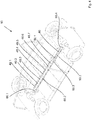
- Figure 1a shows an electric car 10 according to the invention in the form of an electric car, which has a first axle 12 in the form of a front axle and a second axle 14 in the form of a rear axle. Wheels 16.1, 16.2 are attached to the first axis 12, wheels 16.3, 16.4 are fastened to the second axis 14.
- An electric motor 18 drives the wheels 16.1, 16.2 of the first axle 12 via a differential gear 20, which can also be called a differential.
- the electric motor 18 is powered by a battery 22.
- the battery 22 comprises at least two, in the present case eight, battery units 24.1, 24.2, ..., 24.8.
- a motor axis of rotation D 18 runs between the battery units 24.1, 24.3, 24.5, 24.7 on the one hand and 24.2, 24.4, 24.6 and 24.8 on the other.
- a mass m r of the battery units 24.1, 24.3, 24.5 and 24.7 arranged on the right side of the motor rotation axis D 18 corresponds to a mass m l of the battery elements on the left of the motor rotation axis D 18 , that is to say in the present case the battery elements 24.2, 24.4, 24.6 and 24.8.
- the feature that the two masses m r , m l correspond to one another means in particular that the two masses differ from one another by at most 20%, preferably at most 15%.
- the electric car 10 has a vehicle floor 25. In the present embodiment, both the battery 22 and the electric motor 18 are mounted on the vehicle floor 25.
- the electric car 10 also includes components not shown, such as an outer shell, in particular made of sheet metal, as well as seats and a steering.
- Figure 1a also shows that the center of gravity of the electric motor S 18 is located in a central longitudinal quarter LQ, in particular a longitudinal fifth. In general, it is favorable if the center of gravity of the electric motor S 18 is as close as possible to a center line M.
- a length L 18 of the electric motor 18 in the present embodiment is 0.4 times the center distance A.
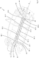
- Figure 1b shows the electric car 10 in a view from behind. It can be seen that an electric motor height h M corresponds to a battery height h B.
- the electric motor height h M is the height of the imaginary cuboid Q 1 of minimum volume, which encloses 90% of the mass of the battery 22.
- Figure 1b also shows a body 26 of the electric car 10. Also shown is a driver's seat 30 and a passenger's seat 32, both of which are arranged on a flat floor 34 of a passenger compartment 36.
- the electric motor center of gravity S 18 is at a height H 18 which corresponds to a height H 22 of the battery center of gravity S 22 .
- the electric motor modules 38.i are identical.
- Figure 2 shows that the electric car 10 has an additional transmission 42 between the differential transmission 20 and the electric motor 18.
- the electric motor can be operated at higher speeds than without the gear 42, which is accordingly preferably a reduction gear.
- a length L 18 of the electric motor 18 in the present embodiment is also 0.4 times the center distance A.
- Figure 3 shows a further embodiment of an electric car 10 according to the invention, in which the coupled rotor shafts 41 of the electric motor 18 are rotationally rigidly connected to both the differential 20 and to a second differential 44.
- the end of the coupled rotor shaft 41 is connected to the second differential 44 via a second gear 46.
- a length L 18 of the electric motor 18 in this embodiment is 0.7 times the center distance A.
- FIG 4 shows a fourth embodiment of an electric car 10 according to the invention.
- the electric motor 18 has a plurality of stator coil packages 48.1,..., 48.N 48 (N 48 : number of stator packages).
- the electric motor according to Figure 4 is an inside runner.
- FIG. 5 shows a fifth embodiment of an electric car 10 according to the invention, which has a second electric motor 18 '.
- the second electric motor comprises three electric motor modules 38'.1, 38'.2 and 38.'3.
- the two electric motor modules 38'.1 and 38'.3 are identical in construction.
- the continuous rotor shaft 40 ' runs parallel to the continuous rotor shaft 40 in the technical sense, which means that small deviations of, for example, at most 5 ° can be tolerated.
- Both continuous rotor shafts 40 and 40 'and thus the associated motor axes of rotation D 18 , D' 18 also run - as in the other embodiments - along a longitudinal axis L of the electric car 10.
- the first coupling gear 52 is rotationally rigidly coupled to the first differential 20
- the second coupling gear 54 is rotationally rigidly connected to the second differential 44.
- FIG. 6 shows a sixth embodiment of an electric car 10 according to the invention, in which 4 electric motors 18.1, 18.2, 18.3 and 18.4 are used.
- the first electric motor 18.1 drives the first wheel 16.1 and the second electric motor 18.2 drives the second wheel 16.2.
- the third electric motor 18.3 drives the third wheel 16.3 and the fourth electric motor 18.4 drives the fourth wheel 16.4.
- the electric car 10 also has a schematically drawn motor controller 58, which is connected to all the electric motors and the battery.
- the motor controller 58 is designed to control all electric motors 18.1, ..., 18.4, so that when the electric car 10 is cornering, the different angular velocities of the wheels lead to adapted speeds of the respective electric motors, so that the slip on all wheels 16.i is the same and in Ideally is zero. It is possible that each electric motor is made up of two or more identical electric motor modules.
- All of the electric cars shown have a battery mass center of gravity S 22 (cf. Fig. 1a ) between the axes 12, 14.
- a distance of the battery center of gravity S 22 from a vehicle center of gravity S 10 is at most a quarter of an axis distance A of the two axes 12, 14.
- an electric motor center of gravity S 18 is tight at the center of gravity of the vehicle S 16 , in particular in a central quintile Q along the longitudinal axis L between the axes 12, 14.
- FIG. 1b shows that the battery 22, in particular its galvanic cells, are not located below the electric motor 18.
- all battery modules 24.i are arranged either to the right or to the left of the electric motor 18 with respect to the longitudinal axis L, but not above or below it.
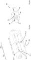
- Figure 7a shows two successive electric motor modules 38.1 and 38.2 in the version of an inner rotor and shaft bearings 60.1, 60.2, with which the continuous rotor shaft 40 is supported and on the vehicle floor 25 (cf. Fig. 4 . 5 ) is attached. It can be seen that the electric motor modules 38.1, 38.2 can be removed by means of detachable fastening elements, in the present case in the form of screws 62.1, ....
- Figure 7b shows in a vertical section through an electric motor module of the inner rotor version that in the grooves 50.1, 50.2 .... of the continuous rotor shaft 40 permanent magnets 64.1 ... are inserted, which are excited by the coil package 48 to rotate.
- Figure 7c shows a side view of the electric motor modules 38.1 and 38.2 of the inner rotor version.
- Figure 8 shows two successive electric motor modules 38.1 and 38.2 of the external rotor version whose stator 66 has a base body 68 and a first cap 70.1 and a second cap 70.2.
- the caps 70.1, 70.2 are reversibly attached to the base body 68 with screws 62.1, 62.2, ..., 62.8.
- Each cap 70.i is firmly connected to at least one stator coil package.
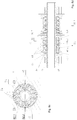
- Figure 8b shows like the other partial figures of the Figure 8 a scale view of the rotor 39, which comprises a shaft 72 in the form of a hollow shaft.
- the shaft 72 has an external toothing 74 on which a rotor bell 78 is seated with an internal toothing 76.
- the rotor bell 78 forms a T-shaped outer section of the rotor 39.
- the rotor 39 also has a second rotor bell 78 '.
- the electric motor comprises at least three rotor bells.
- the permanent magnets of the rotor are not shown for the sake of clarity.
- Figure 8c shows a section through the electric motor module 38.1 of the external rotor version. It can be seen that the permanent magnets 64 are arranged on the inside of a jacket section 80 of the rotor bell 78. These are moved by the stator coil package 48. For example, the permanent magnets 64.i are inserted into grooves in the radially inward side of the jacket section 80.
- Figure 8d shows a sectional view through the electric motor modules 38.1 and 38.2 of the external rotor version with the T-shaped rotor bells 78 and 78 '. It can be seen that coils 82.i are rigidly mechanically and also thermally connected to the cap 70 of the stator 66. In other words, at least one coil package 48, which comprises the coils 82.i, is fastened to the cap 70 of the stator 66 in such a way that waste heat from the coil package 48 is actively or passively removed during operation of the electric car.
Landscapes
- Engineering & Computer Science (AREA)
- Mechanical Engineering (AREA)
- Chemical & Material Sciences (AREA)
- Combustion & Propulsion (AREA)
- Transportation (AREA)
- General Engineering & Computer Science (AREA)
- Electric Propulsion And Braking For Vehicles (AREA)
- Arrangement Or Mounting Of Propulsion Units For Vehicles (AREA)
- Iron Core Of Rotating Electric Machines (AREA)
Description
- Die Erfindung betrifft ein Elektroauto gemäß dem Oberbegriff von Anspruch 1.
- Elektrofahrzeuge werden seit geraumer Zeit hergestellt und erleben eine Renaissance. Im Vergleich zu Fahrzeugen mit Verbrennungsmotor ist ihr Anteil bisher jedoch gering. Auch wenn die Herstellung von Elektrofahrzeugen sich grundsätzlich einfacher und kostengünstiger gestaltet, als die Herstellung von Verbrennungsmotorfahrzeugen, so werden bisher für die unterschiedlichen Leistungsklassen in den Außenabmessungen unterschiedlich große Elektromotoren eingesetzt.
- Aus der
WO 2013/106 049 A1 ist ein Elektrofahrzeug bekannt, bei dem ein Elektromotor aus Batterien mit Strom versorgt wird, die entlang des Mitteltunnels angeordnet sind und dessen Elektromotoren nicht zwischen den Radachsen sondern vor der Vorderachse und hinter Hinterachse angeordnet sind. Ein derartiges Elektroauto ist hinsichtlich seines Antriebs kaum modularisierbar. - Aus der
US 2011/0 259 657 A1 ist ein Elektroauto bekannt, bei dem die Elektromotoren in einer Vielzahl von Konfigurationen angeordnet sein können. Auch ein derartiges Elektrofahrzeug ist hinsichtlich seines Antriebs nur schlecht modularisierbar. - Im
US 2015/0155801 A1 ist ein Elektrofahrzeug in der Form eines Elektrobusses beschrieben, in welchem zwei oder mehrere axial gekoppelte Elektromotoren in Innenläufer-Bauart Verwendung finden. Auch besitzt die dort verwendete Batterie mit einer 2,3-fach höheren Bauhöhe nicht die gleiche Bauhöhe wie der Elektromotor. - Die
DE 10 2011 053 254 A1 beschreibt ein Baukastensystem für ein modular aufgebautes Elektrofahrzeug, bei dem die Batterie erneut entlang des Mitteltunnels verläuft. Die Drehachsen der Elektromotoren verlaufen quer zur Längsachse des Fahrzeugs. Bei einem derartigen Elektrofahrzeug sind der Modularisierung des Elektromotorantriebs enge Grenzen gesetzt. - Aus der
US 2015/0 165 900 A1 ist ein Elektrofahrzeug bekannt, bei dem ein einzelner Elektromotor zentral zwischen den Achsen angeordnet ist. Die Batterien sind im Bereich hinter der Hinterachse angeordnet. Auch ein solches Fahrzeug ist nicht modularisierbar. - Die Anforderungen an ein Elektrofahrzeug sind, dass es hinsichtlich seines Antriebs möglichst modularisierbar ist, damit mehrere Motorisierungen mit geringem Aufwand angeboten werden können. Zudem müssen die Elektromotoren bei möglichst kompakten Außenabmessungen besonders drehmomentstark sein. Bislang ist es nicht gelungen, diese Anforderungen umzusetzen.
- Der Erfindung liegt die Aufgabe zugrunde, ein verbessertes Elektrofahrzeug vorzuschlagen.
- Die Erfindung löst das Problem durch ein Elektroauto mit den Merkmalen von Anspruch 1.
- Vorteilhaft an diesem Elektroauto ist, dass der Elektromotor und die Batterie auf gleicher Höhe angeordnet sind und dazu führt, dass die Bauhöhe, die für den Elektromotor und die Batterie vorgesehen werden muss, klein gewählt werden kann. Besonders günstig ist es, wenn, was ebenfalls eine bevorzugte Ausführungsform darstellt, sowohl die Batterien als auch der Elektromotor unterhalb eines Niveaus angeordnet ist, auf dem der Fahrersitz sich befindet. In anderen Worten sind Motor und Batterie dann vollständig unter dem Fahrersitz angeordnet. Das führt dazu, dass der Schwerpunkt des Elektroautos so tief liegt, dass sich eine gute Straßenlage ergibt.
- Besonders vorteilhaft ist, dass diese Anpassung der Bauhöhen eine Modularisierung von Batterien und Elektromotor ermöglicht. Das wiederum gestattet es, die Herstellung von verschiedenen Modellen mit unterschiedlichen Antriebsleistungen rationell zu planen und zu fertigen.
- Vorzugsweise hat das Elektroauto vier Räder.
- Unter der Achse wird das Bauteil verstanden, an dem die Räder befestigt sind. Die mathematische Achse, um die die Räder rotieren, wird als Drehachse bezeichnet.
- Die Elektromotor-Bauhöhe wird insbesondere berechnet anhand desjenigen gedachten Quaders minimalen Volumens, der 90% der Masse des Elektromotors enthält. In anderen Worten ist es möglich, dass kleinere Bereiche des Elektromotors auskragen oder Vorsprünge ausbilden, wenngleich dies oft nicht vorteilhaft ist.
- Die Batterie-Bauhöhe wird auf die gleiche Weise berechnet.
- Unter dem Merkmal, dass der Elektromotor und die Batterie auf gleicher Höhe angeordnet sind, wird insbesondere verstanden, dass ein vertikaler Abstand des Batterie-Massenschwerpunkts vom Elektromotor-Massenschwerpunkt höchstens ein Viertel, insbesondere höchstens ein Fünftel, der Bauhöhe des Elektromotors beträgt.
- Unter einer Batterie wird eine Zusammenschaltung mehrerer galvanischer Zellen verstanden. Insbesondere umfasst die Batterie galvanische Lithium-Zellen. Alternativ oder zusätzlich kann die Batterie zumindest eine Flussbatterie oder zumindest ein Flussbatterie-Modul umfassen, beispielsweise eine Vanadium-Flussbatterie.
- Günstig ist es, wenn der Elektromotor die Räder einer Achse über ein Differential antreibt. Alternativ ist es aber auch möglich, dass mehr als ein Elektromotor vorhanden ist, wobei zumindest einer der Elektromotoren lediglich ein Rad antreibt. Die etwaigen Drehgeschwindigkeitsunterschiede bei der Kurvenfahrt werden in diesem Fall elektronisch ausgeregelt.
- Vorzugsweise ist ein Elektroauto ein Fahrzeug, dessen Antriebsdrehmoment bei konstant 50 Kilometer pro Stunde zu zumindest 50% vom Elektromotor stammt. Besonders günstig ist es, wenn es sich um ein reines Elektroauto handelt, das heißt, dass die Räder ausschließlich elektrisch angetrieben sind.
- Günstig ist es, wenn der Elektromotor vollständig zwischen den Achsen angeordnet ist. Hierunter ist insbesondere zu verstehen, dass der Elektromotor in einem Bereich angeordnet ist, der sich zwischen zwei Ebenen befindet, wobei jede der Ebenen vertikal verläuft und durch die Drehachsen der Räder des Elektroautos bei Geradeausfahrt geht. Besonders günstig ist es, wenn der Abstand des Elektromotors zur ersten Achse möglichst wenig, vorzugsweise höchstens um den Faktor zwei, von einem Abstand von der zweiten Achse abweicht. Ein derartiges Elektroauto hat ein besonders kleines Massenträgheitsmoment bezüglich der Drehung um die Hochachse. Das Elektroauto hat daher besonders vorteilhafte Fahreigenschaften.
- Günstig ist es, wenn der Abstand zwischen dem bezüglich der Längsachse des Elektroautos vordersten Ende des Elektromotors, insbesondere des vorderen Elektromotor-Moduls, und dem hintersten Ende des Elektromotors, vorzugsweise dem hintersten Elektromotor-Modul, höchsten 15 % des Achsabstands beträgt.
- Vorzugsweise besitzt das Elektroauto einen Fahrzeugboden. Der Elektromotor und die Batterie können auf dem Fahrzeugboden angeordnet sein. Alternativ sind sie am Fahrzeugboden hängend montiert. Die hängende Montage hat den Vorteil, besonders leicht durchgeführt werden zu können. Die Montage auf dem Fahrzeugboden bietet Vorteil bei dem Schutz der Batterien gegen Einwirkungen von außen.
- Gemäß einer bevorzugten Ausführungsform ist der Elektromotor aus mindestens drei, vorzugsweise mindestens vier, Elektromotor-Modulen aufgebaut, wobei die Elektromotor-Module bezüglich einer Motor-Drehachse hintereinander angeordnet sind und mehrere gekoppelte Rotorwellen oder eine gemeinsame Rotorwelle haben. Die Elektromotor-Module sind vorzugsweise baugleich ausgebildet und miteinander verbunden.
- Vorzugsweise ist zwischen zwei Elektromotor-Modulen ein Wellenlager für die durchgehende Rotorwelle des Elektromotors angeordnet. Auf diese Weise werden Schwingungen des Rotors vermindert, wenn das Auto über unebenen Untergrund fährt.
- Vorzugsweise ist der Elektromotor ein Außenläufer, wobei der Rotor einen, insbesondere T-förmigen Außenabschnitt hat und wobei der Stator zumindest ein Spulenpaket aufweist, das zwischen dem Außenabschnitt und der Rotorwelle angeordnet ist. Der, insbesondere T-förmige, Außenabschnitt kann auch als Rotorglocke bezeichnet werden. Auf diese Weise ergibt sich ein hohes Drehmoment bei gleichzeitig geringer Bauhöhe. In anderen Worten ragt das zumindest eine Spulenpaket zwischen den Außenabschnitt und dem verbleibenden Teil des Rotors. Es ist möglich, nicht aber notwendig, dass die Rotorglocke symmetrisch bezüglich einer Symmetrieebene, die senkrecht zur Motor-Drehachse verläuft, ist. Die Bezeichnung T-förmig bezieht sich auf einen Querschnitt in einer Ebene, in der die Mittelpunktlinie liegt.
- Gemäß einer bevorzugten Ausführungsform sind die Rotorglocke und die Rotorwelle formschlüssig miteinander verbunden. Beispielsweise hat die Rotorglocke eine Innenverzahnung und die Welle des Rotors eine Außenverzahnung, wobei die Rotorglocke mittels der Innenverzahnung und der Außenverzahnung drehfest mit der Welle verbunden ist. Das erleichtert die Montage.
- Vorzugsweise umfasst der Außenabschnitt auf seiner radial einwärtigen Seite Permanentmagnete. Das zumindest eine Spulenpaket ist elektrisch, mechanisch und/oder thermisch mit einer Kappe des Stators kontaktiert. In anderen Worten ist das zumindest eine Spulenpaket so an der Kappe des Stators befestigt, dass die Abwärme des Spulenpakets aktiv oder passiv beim Betrieb des Elektroautos abgeführt wird.
- Die Elektromotor-Module sind vorzugsweise elektrisch kommutierte permanentmagneterregte Synchronmotoren.
- Besonders günstig ist es, wenn das Elektroauto einen elektronischen Motorregler aufweist, mittels dem die Gleichspannung der Batterie in eine Wechselspannung einer variabel vorgebbaren Frequenz umwandelbar ist. Diese Wechselspannung wird an die Elektromotor-Module angelegt, sodass diese mit einer Drehfrequenz drehen, die gleich der vorgebbaren Frequenz oder einem Bruchteil davon ist.
- Günstig ist es, wenn der Elektromotor eine Baulänge hat, die zumindest einem Drittel, vorzugsweise zumindest der Hälfte, eines Achsabstands zwischen der ersten Achse und der zweiten Achse entspricht. Die große Baulänge führt zu einem hohen maximalen Drehmoment. Bisher ist es zum Erzielen eines hohen Drehmoments vorteilhaft, den Rotordurchmesser zu erhöhen. Aufgrund der wünschenswerten modularen Bauweise des Elektromotors kann hier jedoch die Baulänge durch die mehrfache Verwendung gleicher Elektromotormodule vergrößert werden, ohne dass die ansonsten üblichen Nachteile wie beispielsweise eine aufwändigere Fertigung entstehen.
- Günstig ist es, wenn der Rotor eine Hohlwelle aufweist. Auf diese Weise wird die schwingende Masse reduziert. Zudem ist es möglich, dass der Rotor von innen gekühlt wird, indem ein Kühlfluid, insbesondere Luft oder Kühlflüssigkeit, beispielsweise Wasser, durch die Hohlwelle geschickt wird.
- Günstig ist es, wenn die Batterie so angeordnet ist, dass 80, vorzugsweise zumindest 85, Gewichtsprozent der Masse der Batterie zwischen den Achsen angeordnet sind. Diese Anordnung führt zu besonders guten Fahreigenschaften des Elektroautos.
- Vorzugsweise liegt ein Elektromotor-Massenschwerpunkt des Elektromotors zwischen den Achsen, insbesondere in einem zentralen Drittel, vorzugsweise einem zentralen Fünftel (Quintil), zwischen den Achsen. Wenn das Auto so steht, dass beide Achsen sich entlang einer horizontalen Ebene erstrecken, verläuft eine erste Vertikalebene so, dass sich die erste Achse entlang der ersten Vertikalachse erstreckt. Eine zweite Vertikalachse verläuft so, dass sich die zweite Achse entlang der zweiten Vertikalachse erstreckt. Die beiden Vertikalachsen verlaufen parallel zueinander. Das zentrale Drittel ist derjenige Bereich zwischen zwei weiteren Vertikalachsen, deren Abstand von einem Drittel des Abstands von erster und zweiter Vertikalachse entspricht, deren Abstand von einem Mittelpunkt, der genau zwischen der ersten und der zweiten Vertikalachse liegt, gleich ist. Der entsprechende Massenschwerpunkt ist dann zwischen diesen beiden zusätzlichen Vertikalachsen angeordnet. Eine derartige Anordnung der Batterie bzw. des Elektromotors führt zu besonders günstigen Fahreigenschaften, da das Massenträgheitsmoment bezüglich einer Gier-, Nick- oder Rollbewegung des Elektroautos besonders klein ist.
- Günstig ist es, wenn der Elektromotor-Massenschwerpunkt bezüglich der Längsrichtung des Elektroautors im zentralen Drittel, insbesondere dem zentralen Fünftel, liegt. Das zentrale Drittel erstreckt sich in Richtung quer zur Längsrichtung, also in der Erstreckungsrichtung der Achsen. Die geometrische Mittelpunktlinie bezüglich der Längsrichtung ist die Gerade, die den gleichen Abstand zu linkem und rechtem Vorderrad und linkem und rechtem Hinterrad hat. Die Mittelpunktlinie verläuft zentrisch durch das zentrale Drittel.
- Vorzugsweise hat der Fahrgastraum einen mitteltunnelfreien Boden. Da die Batterie und der Elektromotor gleiche Bauhöhen haben, ist ein Mitteltunnel zum Aufnehmen eines vergrößerten Elektromotors entbehrlich. Der Erfindung liegt die Erkenntnis zugrunde, dass es vorteilhaft ist, das Drehmoment des Elektromotors dadurch zu erhöhen, dass er lang ausgebildet wird. Bisherige Autos setzen auf Elektromotoren mit möglichst großem Rotor-Durchmesser und geringer Baulänge, um das Drehmoment zu erhöhen. Das aber führt zu einer nachteiligen Lage des Elektromotor-Massenschwerpunkts und/oder macht einen Mitteltunnel notwendig. Das erfindungsgemäße Elektroauto kommt ohne Mitteltunnel aus.
- Unter dem Merkmal, dass der Fahrgastraum einen mitteltunnelfreien Boden hat, wird insbesondere verstanden, dass der Boden im technischen Sinne eben ist. In anderen Worten sind Erhebungen zwar möglich, die maximale Erhebung ist aber klein. Insbesondere ist die maximale Erhebung zwischen Fahrer- und Beifahrersitz höchstens 10 Zentimeter über einer gedachten Ausgleichsebene durch den Boden des Fahrgastraumes.
- Vorzugsweise besitzt das Elektroauto eine Längsachse und die Motor-Drehachse erstreckt sich entlang der Längsachse. Hierunter ist insbesondere zu verstehen, dass es zwar möglich, nicht aber notwendig ist, dass sich die Motor-Drehachse parallel zur Längsachse erstreckt. Insbesondere ist ein Versatzwinkel zwischen der Motor-Drehachse und der Längsachse möglich, der vorzugsweise höchstens 20°, insbesondere höchstens 5°, beträgt.
- Vorzugsweise umfasst die Batterie zumindest zwei Batterie-Einheiten, wobei die Motor-Drehachse zwischen den Batterie-Einheiten verläuft. Unter dem Merkmal, dass die Motor-Drehachse zwischen den Batterie-Einheiten verläuft, wird verstanden, dass eine Projektion der Motor-Drehachse auf eine Ebene, entlang der sich die erste Achse und die zweite Achse erstrecken, zwischen einem ersten Batterieeinheit-Massenschwerpunkt der ersten Batterie-Einheit und einem zweiten Batterieeinheit-Massenschwerpunkt der zweiten Batterie-Einheit verläuft. Besonders günstig ist es, wenn die Drehachse so verläuft, dass - bezogen auf eine jeweilige Projektion auf die Ebene, entlang der die beiden Achsen verlaufen - die erste Batterie-Einheit von der zweiten Batterie-Einheit getrennt ist. In anderen Worten verläuft kein galvanisches Element einer Batterie-Einheit von einer Seite der Projektion der Drehachse auf die andere. Es ist allerdings möglich, dass elektrische Verbinder, insbesondere Kabel, von einer Seite der Projektion der Drehachse auf die andere Seite verlaufen.
- Vorzugsweise besitzt der Elektromotor einen Rotor mit Permanentmagneten. Es ist dabei möglich, dass der Elektromotor ein Innenläufermotor ist. Eine weniger häufige, aber meist bessere Alternative ist der bei sonst gleichen Außenabmessungen wesentlich drehmomentstärkere Außenläufermotor.
- Das Elektroauto besitzt vorzugsweise ein Differential und ein Getriebe, das im Drehmomentfluss zwischen dem Motor und dem Differential angeordnet ist. Es ist möglich, nicht aber notwendig, dass das Elektroauto ein zweites Differential und eines zweites Getriebe aufweist, das im Drehmomentfluss zwischen dem Motor und dem zweiten Differential angeordnet ist. Das erste Differential treibt vorzugsweise die Räder der Vorderachse an. Das zweite Differential treibt vorzugsweise die Räder der Hinterachse an. Mit zwei Differentialen kann ein Vierradantrieb realisiert werden. Das erste Differential und/oder das zweite Differential sind jeweils drehstarr mit dem entsprechenden Rotor des Elektromotors gekoppelt.
- Der Elektromotor kann besonders einfach gefertigt werden, wenn er einen Rotor mit Permanentmagneten aufweist, wobei der Rotor in Längsrichtung verlaufende Nuten aufweist, in denen die Permanentmagneten angeordnet sind. Beispielsweise sind die Permanentmagneten in die Nuten eingeschoben.
- Um besonders hohe Drehmomente zu erzielen und/oder einfach einen Vierradantrieb zu realisieren ist es günstig, wenn das Elektroauto einen zweiten Elektromotor, der aus zumindest zwei, insbesondere zumindest drei, zumindest vier, zumindest fünf, zumindest sechs oder mehr, Zweitelektromotor-Modulen aufgebaut ist, umfasst, wobei die Zweitelektromotor-Module einen gemeinsamen zweiten Rotor aufweisen und wobei der erste Rotor und der zweite Rotor parallel zueinander verlaufen. Es ist dabei möglich, dass der erste Elektromotor die Räder der ersten Achse antreibt und der zweite Elektromotor die Räder der zweiten Achse antreibt. Alternativ ist es auch möglich, dass der erste Elektromotor und der zweite Elektromotor gemeinsam die Räder einer der Achsen, beispielsweise der Vorderachse und/oder der Hinterachse, antreiben. Die Zahl der Zweitelektromotor-Module ist vorzugsweise kleiner als 30.
- Gemäß einer bevorzugten Ausführungsform umfasst der Elektromotor einen zweiten Elektromotor, der vorzugsweise aus zumindest zwei Elektromotor-Modulen aufgebaut ist, einen dritten Elektromotor, der vorzugsweise aus zumindest zwei Elektromotor-Modulen aufgebaut ist, und einen vierten Elektromotor, der vorzugsweise aus zumindest zwei Elektromotor-Modulen aufgebaut ist, wobei jeder der Elektromotoren jeweils ein Rad, insbesondere über ein Winkelgetriebe, antreibt. Es ist günstig, wenn alle Elektromotor-Module baugleich sind. Es ist dann günstig, wenn alle Motoren von einer Motorsteuerung so angesteuert sind, dass sie ein gleiches Drehmoment auf das jeweilige Rad aufbringen, wobei vorzugsweise ein Durchdrehen unterdrückt wird. Eine solche Anti-Schlupf-Regelung gehört zum Stand der Technik und wird daher nicht weiter erläutert.
- Vorzugsweise weist der Stator einen Basiskörper und ein zweites Spulenpaket auf, wobei das Spulenpaket an einer Kappe des Stators befestig ist und wobei die Kappe reversibel am Basiskörper befestigt ist. So ist der Elektromotor leicht zu montieren.
- Im Folgenden wird die Erfindung anhand der beigefügten Zeichnungen näher erläutert. Dabei zeigt
- Figur 1a
- eine dreidimensionale Teil-Ansicht auf ein erfindungsgemäßes Elektroauto gemäß einer ersten Ausführungsform,
- Figur 1b
- das Elektroauto gemäß
Figur 1a in einer Schnittansicht von hinten, - Figur 2
- ein Elektroauto gemäß einer zweiten Ausführungsform,
- Figur 3
- ein erfindungsgemäßes Elektroauto gemäß einer dritten Ausführungsform,
- Figur 4
- ein erfindungsgemäßes Elektroauto gemäß einer vierten Ausführungsform,
- Figur 5
- ein erfindungsgemäßes Elektroauto gemäß einer fünften Ausführungsform,
- Figur 6
- ein erfindungsgemäßes Elektroauto gemäß einer sechsten Ausführungsform,
- Figur 7
- mit den Teilfiguren 7a und 7b als isometrische Ansichten und Teilfigur 7c als Schnittdarstellung eines Elektromotors als Innenläufer für ein erfindungsgemäßes Elektroauto und
- Figur 8
- mit den Teilfiguren 8a und 8b, als isometrische Ansichten und mit den Teilfiguren 8c und 8d als Schnittdarstellungen eines erfindungsgemäßen Elektromotors als Außenläufer für ein erfindungsgemäßes Elektroauto.
-
Figur 1a zeigt ein erfindungsgemäßes Elektroauto 10 in Form eines Elektroautos, das eine erste Achse 12 in Form einer Vorderachse und eine zweite Achse 14 in Form einer Hinterachse aufweist. An der ersten Achse 12 sind Räder 16.1, 16.2 befestigt, an der zweiten Achse 14 sind Räder 16.3, 16.4 befestigt. Ein Elektromotor 18 treibt über ein Differentialgetriebe 20, das auch Differential genannt werden kann, die Räder 16.1, 16.2 der ersten Achse 12 an. - Der Elektromotor 18 wird von einer Batterie 22 mit Strom versorgt. Die Batterie 22 umfasst zumindest zwei, im vorliegenden Fall acht, Batterie-Einheiten 24.1, 24.2, ..., 24.8.
- Es ist zu erkennen, dass eine Motor-Drehachse D18 zwischen den Batterie-Einheiten 24.1, 24.3, 24.5, 24.7 einerseits und 24.2, 24.4, 24.6 und 24.8 andererseits verläuft. Eine Masse mr der rechtsseitig der Motor-Drehachse D18 angeordneten Batterie-Einheiten 24.1, 24.3, 24.5 und 24.7 entspricht einer Masse ml der Batterie-Elemente links der Motor-Drehachse D18, also im vorliegenden Fall der Batterie-Elemente 24.2, 24.4, 24.6 und 24.8.
- Unter dem Merkmal, dass die beiden Massen mr, ml einander entsprechen, wird insbesondere verstanden, dass die beiden Massen um höchstens 20%, vorzugsweise höchstens 15%, voneinander abweichen.
- Das Elektroauto 10 besitzt einen Fahrzeugboden 25. In der vorliegenden Ausführungsform sind sowohl die Batterie 22 als auch der Elektromotor 18 auf dem Fahrzeugboden 25 montiert. Das Elektroauto 10 umfasst zudem nicht eingezeichnete Komponenten, wie beispielsweise eine Außenhülle, insbesondere aus Blech, sowie Sitze und eine Lenkung.
-
Figur 1a zeigt zudem, dass der Elektromotor-Massenschwerpunkt S18 sich in einem zentralen Längs-Viertel LQ, insbesondere Längs-Fünftel, befindet. Generell ist es günstig, wenn der Elektromotor-Massenschwerpunkt S18 möglichst dicht an einer Mittelpunktlinie M liegt. - Es ist zudem zu erkennen, dass alle Batterie-Module 24 angeordnet sind und damit die Batterie 22 zwischen den Achsen 12, 14 angeordnet ist. Es ist allerdings auch möglich, dass ein Teil der Batterie-Module 24.j (j=1, 2, ..., Anzahl der Batterie-Module) jenseits der Achsen angeordnet ist, günstig ist es aber, wenn zumindest 80 Gewichtsprozent der Masse der Batterie-Module 24.j zwischen den Achsen angeordnet ist. Eine Baulänge L18 des Elektromotors 18 beträgt in der vorliegenden Ausführungsform das 0,4-fache des Achsabstands A.
-
Figur 1b zeigt das Elektroauto 10 in einer Ansicht von hinten. Es ist zu erkennen, dass eine Elektromotor-Bauhöhe hM einer Batterie-Bauhöhe hB entspricht. Die Elektromotor-Bauhöhe hM ist die Höhe desjenigen gedachten Quaders Q1 minimalen Volumens, der 90% der Masse der Batterie 22 umschließt.Figur 1b zeigt zudem eine Karosserie 26 des Elektroautos 10. Eingezeichnet ist zudem ein Fahrersitz 30 und ein Beifahrersitz 32, die beide auf einem ebenen Boden 34 eines Fahrgastraums 36 angeordnet sind. - Es ist zu erkennen, dass der Elektromotor-Massenschwerpunkt S18 auf einer Höhe H18 liegt, die einer Höhe H22 des Batterie-Massenschwerpunkt S22 entspricht.
-
Figur 2 zeigt eine zweite Ausführungsform eines erfindungsgemäßen Elektroautos 10, bei der der Elektromotor 18 aus drei hintereinander gekoppelten Elektromotor-Modulen 38.1, 38.2, 38.3 aufgebaut ist. Alle drei Elektromotor-Module 38.1, 38.2, 38.3 sind baugleich und weisen miteinander gekoppelte Rotorwellen 41 auf. Es ist möglich, nicht aber notwendig, dass wie in der vorliegenden Ausführungsform jedes Elektromotor-Modul 38.i (i = 1, ... N; N: Anzahl der Elektromotor-Module) ein eigenes Rotorelement aufweist, wobei die einzelnen Rotorelemente miteinander verbunden sind und somit den Rotor 39 bilden. Es ist auch möglich, dass der Rotor fügestellenfrei ausgebildet ist. Die Elektromotor-Module 38.i sind baugleich. -
Figur 2 zeigt, dass das Elektroauto 10 ein zusätzliches Getriebe 42 zwischen dem Differentialgetriebe 20 und dem Elektromotor 18 aufweist. Auf diese Weise ist eine einfache Anpassung für die Rotordrehzahl an die Raddrehzahl möglich. Insbesondere kann der Elektromotor mit höheren Drehzahlen betrieben werden als ohne das Getriebe 42, bei dem es sich entsprechend vorzugsweise um ein Untersetzungsgetriebe handelt. - Eine Baulänge L18 des Elektromotors 18 beträgt in der vorliegenden Ausführungsform ebenfalls das 0,4-fache des Achsabstands A.
-
Figur 3 zeigt eine weitere Ausführungsform eines erfindungsgemäßen Elektroautos 10, bei dem die gekoppelten Rotorwellen 41 des Elektromotors 18 sowohl mit dem Differential 20 als auch mit einem zweiten Differential 44 drehstarr verbunden sind. Im vorliegenden Fall ist das Ende der gekoppelten Rotorwelle 41 über ein zweites Getriebe 46 mit dem zweiten Differential 44 verbunden. - Anders als in der Ausführungsform gemäß der
Figur 2 besitzt der Elektromotor 18 fünf Elektro-Module 38.i (N = 5). Ein maximales Drehmoment Mmax des Elektromotors gemäßFigur 2 beträgt Mmax = 300 Nm. Hingegen beträgt das maximale Drehmoment Mmax für das Elektroauto gemäßFigur 3 Mmax = 500 Nm. Es ist zu erkennen, dass das maximale Drehmoment mit der Anzahl der Elektromotor-Module N linear ansteigt. - Eine Baulänge L18 des Elektromotors 18 beträgt in dieser Ausführungsform das 0,7-fache des Achsabstands A.
-
Figur 4 zeigt eine vierte Ausführungsform eines erfindungsgemäßen Elektroautos 10. Der Elektromotor 18 weist mehrere Stator-Spulenpakete 48.1, ..., 48.N48 (N48: Zahl der Statorpakete) auf. Jedes Stator-Spulenpaket 48.j (j = 1, ..., N48) lässt sich entfernen, ohne dass die durchgehende Rotorwelle 40 ausgebaut werden muss. Es ist zu erkennen, dass die durchgehende Rotorwelle 40 Nuten 50.1, 50.2 aufweist, in die der Übersichtlichkeit halber nicht eingezeichnete Permanentmagneten eingeschoben sind. Der Elektromotor gemäßFigur 4 ist ein Innenläufer. -
Figur 5 zeigt eine fünfte Ausführungsform eines erfindungsgemäßen Elektroautos 10, das einen zweiten Elektromotor 18' aufweist. Der zweite Elektromotor umfasst drei Elektromotor-Module 38'.1, 38'.2 und 38.'3. Die beiden Elektromotor-Module 38'.1, und 38'.3 sind baugleich. Die durchgehende Rotorwelle 40' verläuft im technischen Sinne parallel zur durchgehenden Rotorwelle 40, das heißt, dass kleine Abweichungen von beispielsweise höchstens 5° tolerierbar sind. Beide durchgehenden Rotorwellen 40 und 40' und damit die zugeordneten Motor-Drehachsen D18, D'18 verlaufen zudem - wie bei den übrigen Ausführungsformen - entlang einer Längsachse L des Elektroautos 10. - Die beiden Elektromotoren 18, 18' treiben gemeinsam ein erstes Koppelgetriebe 52 und ein zweites Koppelgetriebe 54 an. Das erste Koppelgetriebe 52 ist drehstarr mit dem ersten Differential 20 gekoppelt, das zweite Koppelgetriebe 54 ist mit dem zweiten Differential 44 drehstarr verbunden.
-
Figur 6 zeigt eine sechste Ausführungsform eines erfindungsgemäßen Elektroautos 10, bei dem 4 Elektromotoren 18.1,18.2,18.3 und 18.4 verwendet werden. Dabei treibt der erste Elektromotor 18.1 das erste Rad 16.1 und der zweite Elektromotor 18.2 das zweite Rad 16.2 an. Der dritte Elektromotor 18.3 treibt das dritte Rad 16.3 und der vierte Elektromotor 18.4 treibt das vierte Rad 16.4 an. Das Elektroauto 10 besitzt zudem eine schematisch eingezeichnete Motorsteuerung 58, die mit allen Elektromotoren und der Batterie verbunden ist. Die Motorsteuerung 58 ist ausgebildet zum Ansteuern aller Elektromotoren 18.1, ..., 18.4, sodass bei Kurvenfahrt des Elektroautos 10 die unterschiedlichen Winkelgeschwindigkeiten der Räder zu angepassten Drehzahlen der jeweiligen Elektromotoren führen, sodass der Schlupf bei allen Rädern 16.i gleich groß ist und im Idealfall null beträgt. Es ist möglich, dass jeder Elektromotor aus zwei oder mehr baugleichen Elektromotor-Modulen aufgebaut ist. - Bei allen gezeigten Elektroautos liegt ein Batteriemassenschwerpunkt S22 (vgl.
Fig. 1a ) zwischen den Achsen 12, 14. Bei den gezeigten Ausführungsformen beträgt ein Abstand des Batterie-Massenschwerpunkts S22 von einem Fahrzeug-Massenschwerpunkt S10 höchstens ein Viertel eines Achsabstands A der beiden Achsen 12, 14. Ebenso liegt ein Elektromotor-Massenschwerpunkt S18 dicht beim Fahrzeug-Massenschwerpunkt S16, insbesondere in einem zentralen Quintil Q entlang der Längsachse L zwischen den Achsen 12, 14. -
Figur 1b zeigt, dass sich die Batterie 22, insbesondere deren galvanische Zellen, nicht unterhalb des Elektromotors 18 befinden. In anderen Worten sind alle Batterie-Module 24.i bezüglich der Längsachse L entweder rechts oder links des Elektromotors 18 angeordnet, nicht aber oberhalb oder unterhalb desselben. -
Figur 7a zeigt zwei hintereinander liegende Elektromotor-Module 38.1 und 38.2 in der Version eines Innenläufers und Wellenlager 60.1, 60.2, mit denen die durchgehende Rotorwelle 40 gelagert und am Fahrzeugboden 25 (vgl.Fig. 4 ,5 ) befestigt ist. Es ist zu erkennen, dass die Elektromotor-Module 38.1, 38.2 mittels lösbarer Befestigungselemente, im vorliegenden Fall in Form von Schrauben 62.1, ... entfernt werden können. - Alle Elektromotor-Module 38.k (k = 1, 2, ... Anzahl der Elektromotor-Module) sind elektrisch kommutierte permanenterregte Synchronmotoren.
-
Figur 7b zeigt in einem Vertikalschnitt durch ein Elektromotor-Modul der Innenläuferversion, dass in die Nuten 50.1, 50.2 ....derdurchgehenden Rotorwelle 40 Permanentmagnete 64.1 ... eingeschoben sind, die vom Spulenpaket 48 zur Rotation angeregt werden. -
Figur 7c zeigt eine Seitenansicht der Elektromotor-Module 38.1 und 38.2der Innenläuferversion. -
Figur 8 zeigt zwei hintereinander liegende Elektromotor-Module 38.1 und 38.2 der Außenläuferversion deren Stator 66 einen Basiskörper 68 sowie eine erste Kappe 70.1 und eine zweite Kappe 70.2 aufweist. Die Kappen 70.1, 70.2 sind mit Schrauben 62.1, 62.2, ..., 62.8 am Basiskörper 68 reversibel befestigt. Jede Kappe 70.i ist mit mindestens einem Stator-Spulenpaket fest verbunden. -
Figur 8b zeigt wie die übrigen Teilfiguren derFigur 8 eine maßstabgemäße Ansicht des Rotors 39, der eine Welle 72 in Form einer Hohlwelle umfasst. Die Welle 72 besitzt eine Außenverzahnung 74, auf der mit einer Innenverzahnung 76 eine Rotorglocke 78 sitzt. Die Rotorglocke 78 bildet einen T-förmigen Außenabschnitt des Rotors 39. Es ist zu erkennen, dass der Rotor 39 zudem eine zweite Rotorglocke 78' aufweist. Selbstverständlich können weitere Rotorglocken vorhanden sein. Beispielsweise umfasst der Elektromotor zumindest drei Rotorglocken. InFig. 8b sind die Permanentmagnete des Rotors der Übersichtlichkeit halber nicht dargestellt. -
Figur 8c zeigt einen Schnitt durch das Elektromotor-Modul 38.1 der Außenläuferversion. Es ist zu erkennen, dass die Permanentmagnete 64 auf einer Innenseite eines Mantelabschnitts 80 der Rotorglocke 78 angeordnet sind. Diese werden von dem Stator-Spulenpaket 48 bewegt. Beispielweise sind die Permanentmagnete 64.i in Nuten in der radial einwärtigen Seite des Mantelabschnitts 80 eingeschoben. -
Figur 8d zeigt eine Schnittansicht durch die Elektromotor-Module 38.1 und 38.2 der Außenläuferversion mit den T-förmigen Rotorglocken 78 und 78'. Es ist zu erkennen, dass Spulen 82.i starr mechanisch und zudem thermisch mit der Kappe 70 des Stators 66 verbunden sind. In anderen Worten ist zumindest ein Spulenpaket 48, das die Spulen 82.i umfasst, so an der Kappe 70 des Stators 66 befestigt, dass Abwärme des Spulenpakets 48 aktiv oder passiv beim Betrieb des Elektroautos abgeführt wird.Bezugszeichenliste 10 Elektroauto 66 Stator 12 erste Achse 68 Basiskörper 14 zweite Achse 70 Kappe 16 Räder 72 Welle 18 Elektromotor 74 Außenverzahnung 20 Differential 76 Innenverzahnung 22 Batterie 78 Rotorglocke 24 Batterie-Modul 80 Mantelabschnitt 25 Fahrzeugboden 82 Spule 26 Karosserie 28 Gelenkwelle A Achsabstand 30 Fahrersitz D18 Motor-Drehachse 32 Beifahrersitz hM Elektromotor-Bauhöhe hB Batterie-Bauhöhe 34 Boden i Laufindex 36 Fahrgastraum 38 Elektromotor-Modul j Laufindex 39 Rotor L Längsachse 40 Rotorwelle, durchgehend ml Masse der Batterie-Elemente links der Motor-Drehachse 41 Rotorwelle, gekoppelt 42 Getriebe mr Masse der Batterie-Elemente rechts der Motor-Drehachse 44 zweites Differential Mmax maximales Drehmoment 46 zweites Getriebe 48 Stator-Spulenpaket N38 Anzahl der Elektromotor-Module 50 Nut N48 Zahl der Statorpakete 52 erstes Koppelgetriebe Q zentrales Perzentil 54 zweites Koppelgetriebe LQ Längs-Viertel 56 Elektromotor-Einheit S22 Batterie-Massenschwerpunkt 58 Motorsteuerung S18 Elektromotor-Massenschwerpunkt 60 Wellenlager S10 Fahrzeug-Massenschwerpunkt 62 Schrauben 64 Permanentmagnet
Claims (15)
- Elektroauto mit(a) einer ersten Achse (12),(b) einer zweiten Achse (14),(c) einem Elektromotor (18) zum Antreiben von zumindest einer der Achsen, der eine Elektromotor-Bauhöhe (hM) hat, und(d) einer Batterie (22) zum Versorgen des Elektromotors (18) mit elektrischer Energie, die eine Batterie-Bauhöhe (hB) hat, wobei(e) die Elektromotor-Bauhöhe (hM) der Batterie-Bauhöhe (hB) entspricht,(f) wobei der Elektromotor (18) und die Batterie auf gleicher Höhe angeordnet sind und(g) ein Batterie-Massenschwerpunkt (S22) der Batterie (22) in einem zentralen Drittel (Q) zwischen den Achsen (12, 14) liegt,dadurch gekennzeichnet, dass(h) der Elektromotor (18) aus zumindest zwei Elektromotor-Modulen (38.1, 38.2) aufgebaut ist,(i) die Elektromotor-Module (38.1, 38.2) bezüglich einer Motor-Drehachse (D18) hintereinander angeordnet sind und(j) die Elektromotor-Module (38.1, 38.2) eine gemeinsame Rotorwelle (40) haben oder gekoppelte Rotorwellen (41) besitzen.
- Elektroauto nach Anspruch 1, dadurch gekennzeichnet, dass(a) der Elektromotor (18) ein Außenläufer ist,(b) ein Rotor (39) des Elektromotors (18) eine T-förmige Rotorglocke (80) hat und(c) ein Stator (66) des Elektromotors (18) zumindest ein Spulenpaket (48), das zwischen der Rotorglocke (80) und der Rotorwelle (40) angeordnet ist, aufweist.
- Elektroauto nach Anspruch 2, dadurch gekennzeichnet, dass die Rotorglocke (78) bezüglich eines Querschnitts in radialer Richtung T-förmig ist.
- Elektroauto nach Anspruch 2 oder 3, dadurch gekennzeichnet, dass(a) die Rotorglocke (78) eine Formschlusskontur wie z.B. eine Innenverzahnung hat,(b) die Rotorwelle (40) eine Formschlusskontur wie z.B. eine Außenverzahnung hat, und(c) die Rotorglocke (78) mittels dieser Formschlusskonturen drehfest mit der Rotorwelle (40) verbunden ist.
- Elektroauto nach einem der vorstehenden Ansprüche, dadurch gekennzeichnet, dass(a) ein Stator (66) des Elektromotors (18) des Elektroautos über eine Kappe (70) mit einem Basiskörper (68) des Elektromotors (18) verbunden ist und mindestens zwei oder mehr Spulenpakete (48.1,48.2, ...) aufweist, und(b) die Spulenpakete (48.1, 48.2) an einer Kappe (70) des Stators (66) befestig sind,(c) wobei die Kappe (70) reversibel am Basiskörper (68) befestigt ist.
- Elektroauto nach einem der vorstehenden Ansprüche, dadurch gekennzeichnet, dass
ein Elektromotor-Massenschwerpunkt (S18) des Elektromotors (18) in einem zentralen Drittel (Q) zwischen den Achsen (12, 14) liegt. - Elektroauto nach einem der vorstehenden Ansprüche, dadurch gekennzeichnet, dass- die Batterie (22) zumindest zwei Batterie-Einheiten aufweist und- die Motor-Drehachse (D18) zwischen den Batterie-Einheiten verläuft.
- Elektroauto nach einem der vorstehenden Ansprüche, gekennzeichnet durch(a) ein Differential (20) und(b) ein Getriebe (42), das im Drehmomentfluss zwischen dem Motor und dem Differential (20) angeordnet ist.
- Elektroauto nach einem der vorstehenden Ansprüche, gekennzeichnet durch(a) ein zweites Differential und(b) ein zweites Getriebe, das im Drehmomentfluss zwischen dem Motor und dem zweiten Differential angeordnet ist.
- Elektroauto nach einem der vorstehenden Ansprüche 1 oder 3 bis 9, dadurch gekennzeichnet, dass- der Elektromotor als Innenläufer eine Rotorwelle (40) mit Permanentmagneten (64) aufweist und dass- die Rotorwelle (40) in Längsrichtung verlaufende Nuten (50) aufweist, in denen die Permanentmagnete (64) angeordnet sind.
- Elektroauto nach einem der vorstehenden Ansprüche, gekennzeichnet durch- einen zweiten Elektromotor (18.2), der aus zumindest zwei Zweitelektromotor-Modulen (38.2) aufgebaut ist,- wobei die Zweitelektromotor-Module (38.2) einen gemeinsamen zweiten Rotor (39.1) aufweisen und- wobei der erste Rotor (39.1) und der zweite Rotor (39.2) parallel zueinander verlaufen.
- Elektroauto nach einem der vorstehenden Ansprüche, gekennzeichnet durch(a) einen zweiten Elektromotor (18.2),(b) einen dritten Elektromotor (18.3), und(c) einen vierten Elektromotor (18.4),(d) wobei jeder der Elektromotoren (18.1, 18.2, 18.3, 18.4) jeweils ein Rad (16.1, 16.2, 16.3, 16.4), insbesondere über ein Winkelgetriebe, antreibt.
- Elektroauto nach einem der vorstehenden Ansprüche, dadurch gekennzeichnet, dass der Elektromotor-Massenschwerpunkt (S18) sich in einem zentralen Längs-Viertel, insbesondere Längs-Fünftel, befindet.
- Elektroauto nach einem der vorstehenden Ansprüche 1 bis 9 oder 11 bis 13, dadurch gekennzeichnet, dass(a) der Elektromotor (18) ein Außenläufer ist,(b) ein Stator (66) des Elektromotors (18) zumindest ein Spulenpaket (48) aufweist, und(c) ein Rotor (39) des Elektromotors (18) eine Rotorglocke (78) aufweist, die das Spulenpaket (48) radial hülsenförmig umgibt.
- Elektroauto nach Anspruch 14, dadurch gekennzeichnet, dass die Rotorglocke (78) bezüglich eines Querschnitts in radialer Richtung T-förmig ist.
Applications Claiming Priority (3)
| Application Number | Priority Date | Filing Date | Title |
|---|---|---|---|
| DE102017111801 | 2017-05-30 | ||
| EP17177846.7A EP3409523A1 (de) | 2017-05-30 | 2017-06-26 | Elektrofahrzeug |
| PCT/EP2018/064243 WO2018220046A2 (de) | 2017-05-30 | 2018-05-30 | Elektroauto |
Publications (2)
| Publication Number | Publication Date |
|---|---|
| EP3448703A2 EP3448703A2 (de) | 2019-03-06 |
| EP3448703B1 true EP3448703B1 (de) | 2020-02-19 |
Family
ID=59215650
Family Applications (2)
| Application Number | Title | Priority Date | Filing Date |
|---|---|---|---|
| EP17177846.7A Withdrawn EP3409523A1 (de) | 2017-05-30 | 2017-06-26 | Elektrofahrzeug |
| EP18729084.6A Active EP3448703B1 (de) | 2017-05-30 | 2018-05-30 | Elektroauto |
Family Applications Before (1)
| Application Number | Title | Priority Date | Filing Date |
|---|---|---|---|
| EP17177846.7A Withdrawn EP3409523A1 (de) | 2017-05-30 | 2017-06-26 | Elektrofahrzeug |
Country Status (7)
| Country | Link |
|---|---|
| US (1) | US11292325B2 (de) |
| EP (2) | EP3409523A1 (de) |
| JP (1) | JP2020521671A (de) |
| KR (1) | KR20200014351A (de) |
| CN (1) | CN110691707A (de) |
| DE (1) | DE102018100777A1 (de) |
| WO (1) | WO2018220046A2 (de) |
Families Citing this family (9)
| Publication number | Priority date | Publication date | Assignee | Title |
|---|---|---|---|---|
| JP6778725B2 (ja) * | 2018-09-12 | 2020-11-04 | 本田技研工業株式会社 | 車両 |
| US11446996B2 (en) * | 2019-11-04 | 2022-09-20 | Toyota Motor Engineering & Manufacturing North America, Inc. | Selectively movable electric propulsion motor and method for positioning the same |
| AT523422B8 (de) | 2020-07-06 | 2022-03-15 | Fill Gmbh | Akkumulator |
| DE102022200232A1 (de) * | 2022-01-12 | 2023-07-13 | Robert Bosch Gesellschaft mit beschränkter Haftung | Fahrgestell eines Fahrzeugs |
| KR102623254B1 (ko) * | 2022-04-29 | 2024-01-10 | 주식회사 엘지에너지솔루션 | 배터리팩 및 배터리팩을 포함하는 전기차량 |
| EP4378721A1 (de) * | 2022-12-01 | 2024-06-05 | Volvo Car Corporation | Achsanordnung für ein elektrofahrzeug, fahrzeug und verfahren zum betreiben einer achsanordnung |
| DE102023117434A1 (de) * | 2023-07-03 | 2025-01-09 | Bayerische Motoren Werke Aktiengesellschaft | Kraftwagen |
| JP2025028587A (ja) * | 2023-08-18 | 2025-03-03 | 株式会社クボタ | 電動車両 |
| CZ310245B6 (cs) * | 2023-12-04 | 2024-12-25 | Tatra Trucks A.S. | Podvozek, zejména těžkého nákladního terénního automobilu, osazený hnacím traktem |
Family Cites Families (26)
| Publication number | Priority date | Publication date | Assignee | Title |
|---|---|---|---|---|
| US5908077A (en) * | 1995-01-30 | 1999-06-01 | Chrysler Corporation | Environmentally sensitive hybrid vehicle |
| US6726438B2 (en) * | 2001-08-23 | 2004-04-27 | General Motors Corporation | Chassis stacking |
| JP2004122972A (ja) * | 2002-10-03 | 2004-04-22 | Toyota Motor Corp | 自動車 |
| CN201054531Y (zh) | 2007-04-24 | 2008-04-30 | 郭金财 | 再生磁能源汽车 |
| JP2010155570A (ja) * | 2008-12-29 | 2010-07-15 | Toyota Motor Corp | 電気自動車の駆動システム |
| US11059522B2 (en) * | 2009-02-24 | 2021-07-13 | Nissan Motor Co., Ltd. | Vehicle battery mounting structure |
| WO2010119320A1 (en) * | 2009-04-15 | 2010-10-21 | Nissan Motor Co., Ltd. | Vehicle component mounting arrangement |
| US10476051B2 (en) * | 2009-04-22 | 2019-11-12 | Tesla, Inc. | Battery pack base plate heat exchanger |
| MX2012002538A (es) * | 2009-08-31 | 2012-07-17 | New Core Inc | Motor electrico de induccion multiple y vehiculo. |
| US7913788B1 (en) * | 2010-02-09 | 2011-03-29 | Gm Global Technology Operations, Llc | Integrated energy storage and rear suspension assembly |
| DE102010017966A1 (de) * | 2010-04-23 | 2011-10-27 | Dr. Ing. H.C. F. Porsche Aktiengesellschaft | Fahrzeug mit elektrischem Antrieb |
| KR101209606B1 (ko) | 2010-08-20 | 2012-12-07 | 현대자동차주식회사 | 전기자동차용 동력전달장치 |
| JP5452447B2 (ja) | 2010-11-08 | 2014-03-26 | 本田技研工業株式会社 | 電動車両のバッテリパックの固定構造及び取り外し方法 |
| WO2013106049A1 (en) * | 2011-04-07 | 2013-07-18 | Trexa Llc | Electric drive vehicle chassis |
| CA2841138A1 (en) * | 2011-07-08 | 2013-01-17 | Consortium De Recherche Brp - Universite De Sherbrooke S.E.N.C. | Electric off-road wheeled vehicle |
| DE102011081836A1 (de) * | 2011-08-30 | 2013-02-28 | Bayerische Motoren Werke Aktiengesellschaft | Elektrisch angetriebene Achse eines zweispurigen Fahrzeugs |
| DE102011053254A1 (de) * | 2011-09-05 | 2013-03-07 | Dr. Ing. H.C. F. Porsche Aktiengesellschaft | Baukastensystem für ein modular aufgebautes Elektrofahrzeug |
| EP2889185B1 (de) * | 2012-08-27 | 2018-02-21 | Nissan Motor Company, Limited | Hochspannungskabelbaumverbindungsstruktur für elektrofahrzeug |
| JP6775968B2 (ja) | 2015-06-04 | 2020-10-28 | シャープ株式会社 | 自律走行車両の車体構造 |
| US9845015B2 (en) | 2015-06-04 | 2017-12-19 | Sharp Kabushiki Kaisha | Vehicle body structure of autonomous vehicle |
| JP6600260B2 (ja) * | 2016-02-04 | 2019-10-30 | 本田技研工業株式会社 | 4輪車両 |
| JP6963867B2 (ja) * | 2017-04-04 | 2021-11-10 | 株式会社ソミックマネージメントホールディングス | 多目的プラットフォーム |
| DE102018202191A1 (de) * | 2018-02-13 | 2019-08-14 | Bayerische Motoren Werke Aktiengesellschaft | Kraftfahrzeug mit mehreren Batteriemodulen |
| US10569641B1 (en) * | 2018-08-07 | 2020-02-25 | Anthony L. Brewer | Multi-passenger electric transporter |
| JP6778725B2 (ja) * | 2018-09-12 | 2020-11-04 | 本田技研工業株式会社 | 車両 |
| CA3141572C (en) * | 2019-05-20 | 2024-02-27 | Canoo Technologies Inc. | Electric vehicle platform |
-
2017
- 2017-06-26 EP EP17177846.7A patent/EP3409523A1/de not_active Withdrawn
-
2018
- 2018-01-15 DE DE102018100777.9A patent/DE102018100777A1/de not_active Withdrawn
- 2018-05-30 KR KR1020197038433A patent/KR20200014351A/ko not_active Ceased
- 2018-05-30 JP JP2019566750A patent/JP2020521671A/ja active Pending
- 2018-05-30 US US16/617,558 patent/US11292325B2/en not_active Expired - Fee Related
- 2018-05-30 CN CN201880034984.1A patent/CN110691707A/zh active Pending
- 2018-05-30 EP EP18729084.6A patent/EP3448703B1/de active Active
- 2018-05-30 WO PCT/EP2018/064243 patent/WO2018220046A2/de not_active Ceased
Non-Patent Citations (1)
| Title |
|---|
| None * |
Also Published As
| Publication number | Publication date |
|---|---|
| DE102018100777A1 (de) | 2018-12-06 |
| CN110691707A (zh) | 2020-01-14 |
| EP3409523A1 (de) | 2018-12-05 |
| KR20200014351A (ko) | 2020-02-10 |
| US11292325B2 (en) | 2022-04-05 |
| US20200247226A1 (en) | 2020-08-06 |
| WO2018220046A2 (de) | 2018-12-06 |
| EP3448703A2 (de) | 2019-03-06 |
| JP2020521671A (ja) | 2020-07-27 |
| WO2018220046A3 (de) | 2019-03-07 |
Similar Documents
| Publication | Publication Date | Title |
|---|---|---|
| EP3448703A2 (de) | Elektroauto | |
| EP3766164B1 (de) | Elektrofahrzeug | |
| EP0706461B1 (de) | Antriebseinheit | |
| EP3597461B1 (de) | Elektrofahrzeug | |
| EP2516191B1 (de) | System zur variablen momentenverteilung | |
| DE102019114828A1 (de) | Achsbaugruppen mit integrierter elektrischer maschine für elektrifizierte fahrzeuge | |
| EP2809536B1 (de) | Elektrischer antriebsstrang für die lenkbare achse eines kraftfahrzeugs | |
| DE202018103672U1 (de) | Bauraumanordnung eines Kfz-Antriebsstrangs, insbesondere mit zwei Elektromotoren | |
| WO2013083243A1 (de) | Antriebsstrang eines rein elektrisch allradbetreibbaren kraftfahrzeuges | |
| DE102011005623A1 (de) | Antriebsvorrichtung zum Antreiben eines Rades einer Federbeinachse für ein elektrisch antreibbares Fahrzeug | |
| EP2500200B1 (de) | Antriebsvorrichtung zum Antreiben eines Rades für ein elektrisch antreibbares Fahrzeug | |
| EP1717090B1 (de) | Allradangetriebenes Kraftfahrzeug | |
| WO2012072310A1 (de) | Elektrofahrzeug und verfahren zum antreiben eines elektrofahrzeugs | |
| WO2004022373A1 (de) | Antriebsachse mit variabler momentenverteilung für ein krafftfahrzeug | |
| EP3075588B1 (de) | Fahrantrieb für ein elektrisch angetriebenes fahrzeug | |
| DE202019103781U1 (de) | Twin-Getriebe mit einer Doppel-Eingangswelle | |
| DE102023202494A1 (de) | Antriebsstrang für ein Fahrzeug | |
| DE102005049709A1 (de) | Allradfahrzeug | |
| DE102008061945A1 (de) | Elektrische Achsantriebseinheit mit variabler Momentenverteilung | |
| WO2017215823A1 (de) | Achsantrieb für ein fahrzeug | |
| DE102018201822A1 (de) | Elektrisches Antriebssystem für ein elektrisch betriebenes Fahrzeug und Verfahren zum Herstellen eines elektrischen Antriebssystems für ein elektrisch betriebenes Fahrzeug | |
| DE202019103771U1 (de) | Doppelgetriebe, insbesondere für einen elektromotorischen Antriebsstrang, mit einer Stützstruktur sowie dazugehörige Lagerbrille | |
| DE102011012447A1 (de) | Antriebseinheit für ein Kraftfahrzeug | |
| DE102022206034A1 (de) | Getriebe für einen Antriebsstrang | |
| DE102009051124B4 (de) | Antriebssystem für ein Elektroradfahrzeug |
Legal Events
| Date | Code | Title | Description |
|---|---|---|---|
| STAA | Information on the status of an ep patent application or granted ep patent |
Free format text: STATUS: UNKNOWN |
|
| STAA | Information on the status of an ep patent application or granted ep patent |
Free format text: STATUS: THE INTERNATIONAL PUBLICATION HAS BEEN MADE |
|
| PUAI | Public reference made under article 153(3) epc to a published international application that has entered the european phase |
Free format text: ORIGINAL CODE: 0009012 |
|
| STAA | Information on the status of an ep patent application or granted ep patent |
Free format text: STATUS: REQUEST FOR EXAMINATION WAS MADE |
|
| 17P | Request for examination filed |
Effective date: 20181026 |
|
| AK | Designated contracting states |
Kind code of ref document: A2 Designated state(s): AL AT BE BG CH CY CZ DE DK EE ES FI FR GB GR HR HU IE IS IT LI LT LU LV MC MK MT NL NO PL PT RO RS SE SI SK SM TR |
|
| AX | Request for extension of the european patent |
Extension state: BA ME |
|
| R17D | Deferred search report published (corrected) |
Effective date: 20190307 |
|
| GRAP | Despatch of communication of intention to grant a patent |
Free format text: ORIGINAL CODE: EPIDOSNIGR1 |
|
| STAA | Information on the status of an ep patent application or granted ep patent |
Free format text: STATUS: GRANT OF PATENT IS INTENDED |
|
| DAV | Request for validation of the european patent (deleted) | ||
| DAX | Request for extension of the european patent (deleted) | ||
| INTG | Intention to grant announced |
Effective date: 20191209 |
|
| GRAS | Grant fee paid |
Free format text: ORIGINAL CODE: EPIDOSNIGR3 |
|
| GRAA | (expected) grant |
Free format text: ORIGINAL CODE: 0009210 |
|
| STAA | Information on the status of an ep patent application or granted ep patent |
Free format text: STATUS: THE PATENT HAS BEEN GRANTED |
|
| AK | Designated contracting states |
Kind code of ref document: B1 Designated state(s): AL AT BE BG CH CY CZ DE DK EE ES FI FR GB GR HR HU IE IS IT LI LT LU LV MC MK MT NL NO PL PT RO RS SE SI SK SM TR |
|
| REG | Reference to a national code |
Ref country code: CH Ref legal event code: EP |
|
| REG | Reference to a national code |
Ref country code: DE Ref legal event code: R096 Ref document number: 502018000796 Country of ref document: DE |
|
| REG | Reference to a national code |
Ref country code: AT Ref legal event code: REF Ref document number: 1234553 Country of ref document: AT Kind code of ref document: T Effective date: 20200315 |
|
| REG | Reference to a national code |
Ref country code: IE Ref legal event code: FG4D Free format text: LANGUAGE OF EP DOCUMENT: GERMAN |
|
| REG | Reference to a national code |
Ref country code: NL Ref legal event code: MP Effective date: 20200219 |
|
| PG25 | Lapsed in a contracting state [announced via postgrant information from national office to epo] |
Ref country code: RS Free format text: LAPSE BECAUSE OF FAILURE TO SUBMIT A TRANSLATION OF THE DESCRIPTION OR TO PAY THE FEE WITHIN THE PRESCRIBED TIME-LIMIT Effective date: 20200219 Ref country code: NO Free format text: LAPSE BECAUSE OF FAILURE TO SUBMIT A TRANSLATION OF THE DESCRIPTION OR TO PAY THE FEE WITHIN THE PRESCRIBED TIME-LIMIT Effective date: 20200519 Ref country code: FI Free format text: LAPSE BECAUSE OF FAILURE TO SUBMIT A TRANSLATION OF THE DESCRIPTION OR TO PAY THE FEE WITHIN THE PRESCRIBED TIME-LIMIT Effective date: 20200219 |
|
| REG | Reference to a national code |
Ref country code: LT Ref legal event code: MG4D |
|
| PG25 | Lapsed in a contracting state [announced via postgrant information from national office to epo] |
Ref country code: BG Free format text: LAPSE BECAUSE OF FAILURE TO SUBMIT A TRANSLATION OF THE DESCRIPTION OR TO PAY THE FEE WITHIN THE PRESCRIBED TIME-LIMIT Effective date: 20200519 Ref country code: LV Free format text: LAPSE BECAUSE OF FAILURE TO SUBMIT A TRANSLATION OF THE DESCRIPTION OR TO PAY THE FEE WITHIN THE PRESCRIBED TIME-LIMIT Effective date: 20200219 Ref country code: SE Free format text: LAPSE BECAUSE OF FAILURE TO SUBMIT A TRANSLATION OF THE DESCRIPTION OR TO PAY THE FEE WITHIN THE PRESCRIBED TIME-LIMIT Effective date: 20200219 Ref country code: IS Free format text: LAPSE BECAUSE OF FAILURE TO SUBMIT A TRANSLATION OF THE DESCRIPTION OR TO PAY THE FEE WITHIN THE PRESCRIBED TIME-LIMIT Effective date: 20200619 Ref country code: GR Free format text: LAPSE BECAUSE OF FAILURE TO SUBMIT A TRANSLATION OF THE DESCRIPTION OR TO PAY THE FEE WITHIN THE PRESCRIBED TIME-LIMIT Effective date: 20200520 Ref country code: HR Free format text: LAPSE BECAUSE OF FAILURE TO SUBMIT A TRANSLATION OF THE DESCRIPTION OR TO PAY THE FEE WITHIN THE PRESCRIBED TIME-LIMIT Effective date: 20200219 |
|
| PG25 | Lapsed in a contracting state [announced via postgrant information from national office to epo] |
Ref country code: NL Free format text: LAPSE BECAUSE OF FAILURE TO SUBMIT A TRANSLATION OF THE DESCRIPTION OR TO PAY THE FEE WITHIN THE PRESCRIBED TIME-LIMIT Effective date: 20200219 |
|
| PG25 | Lapsed in a contracting state [announced via postgrant information from national office to epo] |
Ref country code: CZ Free format text: LAPSE BECAUSE OF FAILURE TO SUBMIT A TRANSLATION OF THE DESCRIPTION OR TO PAY THE FEE WITHIN THE PRESCRIBED TIME-LIMIT Effective date: 20200219 Ref country code: ES Free format text: LAPSE BECAUSE OF FAILURE TO SUBMIT A TRANSLATION OF THE DESCRIPTION OR TO PAY THE FEE WITHIN THE PRESCRIBED TIME-LIMIT Effective date: 20200219 Ref country code: LT Free format text: LAPSE BECAUSE OF FAILURE TO SUBMIT A TRANSLATION OF THE DESCRIPTION OR TO PAY THE FEE WITHIN THE PRESCRIBED TIME-LIMIT Effective date: 20200219 Ref country code: PT Free format text: LAPSE BECAUSE OF FAILURE TO SUBMIT A TRANSLATION OF THE DESCRIPTION OR TO PAY THE FEE WITHIN THE PRESCRIBED TIME-LIMIT Effective date: 20200712 Ref country code: SK Free format text: LAPSE BECAUSE OF FAILURE TO SUBMIT A TRANSLATION OF THE DESCRIPTION OR TO PAY THE FEE WITHIN THE PRESCRIBED TIME-LIMIT Effective date: 20200219 Ref country code: RO Free format text: LAPSE BECAUSE OF FAILURE TO SUBMIT A TRANSLATION OF THE DESCRIPTION OR TO PAY THE FEE WITHIN THE PRESCRIBED TIME-LIMIT Effective date: 20200219 Ref country code: SM Free format text: LAPSE BECAUSE OF FAILURE TO SUBMIT A TRANSLATION OF THE DESCRIPTION OR TO PAY THE FEE WITHIN THE PRESCRIBED TIME-LIMIT Effective date: 20200219 Ref country code: EE Free format text: LAPSE BECAUSE OF FAILURE TO SUBMIT A TRANSLATION OF THE DESCRIPTION OR TO PAY THE FEE WITHIN THE PRESCRIBED TIME-LIMIT Effective date: 20200219 Ref country code: DK Free format text: LAPSE BECAUSE OF FAILURE TO SUBMIT A TRANSLATION OF THE DESCRIPTION OR TO PAY THE FEE WITHIN THE PRESCRIBED TIME-LIMIT Effective date: 20200219 |
|
| REG | Reference to a national code |
Ref country code: DE Ref legal event code: R097 Ref document number: 502018000796 Country of ref document: DE |
|
| PLBE | No opposition filed within time limit |
Free format text: ORIGINAL CODE: 0009261 |
|
| STAA | Information on the status of an ep patent application or granted ep patent |
Free format text: STATUS: NO OPPOSITION FILED WITHIN TIME LIMIT |
|
| 26N | No opposition filed |
Effective date: 20201120 |
|
| PG25 | Lapsed in a contracting state [announced via postgrant information from national office to epo] |
Ref country code: MC Free format text: LAPSE BECAUSE OF FAILURE TO SUBMIT A TRANSLATION OF THE DESCRIPTION OR TO PAY THE FEE WITHIN THE PRESCRIBED TIME-LIMIT Effective date: 20200219 Ref country code: IT Free format text: LAPSE BECAUSE OF FAILURE TO SUBMIT A TRANSLATION OF THE DESCRIPTION OR TO PAY THE FEE WITHIN THE PRESCRIBED TIME-LIMIT Effective date: 20200219 |
|
| PG25 | Lapsed in a contracting state [announced via postgrant information from national office to epo] |
Ref country code: SI Free format text: LAPSE BECAUSE OF FAILURE TO SUBMIT A TRANSLATION OF THE DESCRIPTION OR TO PAY THE FEE WITHIN THE PRESCRIBED TIME-LIMIT Effective date: 20200219 Ref country code: PL Free format text: LAPSE BECAUSE OF FAILURE TO SUBMIT A TRANSLATION OF THE DESCRIPTION OR TO PAY THE FEE WITHIN THE PRESCRIBED TIME-LIMIT Effective date: 20200219 |
|
| REG | Reference to a national code |
Ref country code: BE Ref legal event code: MM Effective date: 20200531 |
|
| PG25 | Lapsed in a contracting state [announced via postgrant information from national office to epo] |
Ref country code: LU Free format text: LAPSE BECAUSE OF NON-PAYMENT OF DUE FEES Effective date: 20200530 |
|
| PG25 | Lapsed in a contracting state [announced via postgrant information from national office to epo] |
Ref country code: IE Free format text: LAPSE BECAUSE OF NON-PAYMENT OF DUE FEES Effective date: 20200530 |
|
| PG25 | Lapsed in a contracting state [announced via postgrant information from national office to epo] |
Ref country code: BE Free format text: LAPSE BECAUSE OF NON-PAYMENT OF DUE FEES Effective date: 20200531 |
|
| REG | Reference to a national code |
Ref country code: CH Ref legal event code: PL |
|
| PG25 | Lapsed in a contracting state [announced via postgrant information from national office to epo] |
Ref country code: CH Free format text: LAPSE BECAUSE OF NON-PAYMENT OF DUE FEES Effective date: 20210531 Ref country code: LI Free format text: LAPSE BECAUSE OF NON-PAYMENT OF DUE FEES Effective date: 20210531 |
|
| PG25 | Lapsed in a contracting state [announced via postgrant information from national office to epo] |
Ref country code: TR Free format text: LAPSE BECAUSE OF FAILURE TO SUBMIT A TRANSLATION OF THE DESCRIPTION OR TO PAY THE FEE WITHIN THE PRESCRIBED TIME-LIMIT Effective date: 20200219 Ref country code: MT Free format text: LAPSE BECAUSE OF FAILURE TO SUBMIT A TRANSLATION OF THE DESCRIPTION OR TO PAY THE FEE WITHIN THE PRESCRIBED TIME-LIMIT Effective date: 20200219 Ref country code: CY Free format text: LAPSE BECAUSE OF FAILURE TO SUBMIT A TRANSLATION OF THE DESCRIPTION OR TO PAY THE FEE WITHIN THE PRESCRIBED TIME-LIMIT Effective date: 20200219 |
|
| PG25 | Lapsed in a contracting state [announced via postgrant information from national office to epo] |
Ref country code: MK Free format text: LAPSE BECAUSE OF FAILURE TO SUBMIT A TRANSLATION OF THE DESCRIPTION OR TO PAY THE FEE WITHIN THE PRESCRIBED TIME-LIMIT Effective date: 20200219 Ref country code: AL Free format text: LAPSE BECAUSE OF FAILURE TO SUBMIT A TRANSLATION OF THE DESCRIPTION OR TO PAY THE FEE WITHIN THE PRESCRIBED TIME-LIMIT Effective date: 20200219 |
|
| PGFP | Annual fee paid to national office [announced via postgrant information from national office to epo] |
Ref country code: GB Payment date: 20240522 Year of fee payment: 7 |
|
| REG | Reference to a national code |
Ref country code: AT Ref legal event code: MM01 Ref document number: 1234553 Country of ref document: AT Kind code of ref document: T Effective date: 20230530 |
|
| PG25 | Lapsed in a contracting state [announced via postgrant information from national office to epo] |
Ref country code: AT Free format text: LAPSE BECAUSE OF NON-PAYMENT OF DUE FEES Effective date: 20230530 |
|
| PG25 | Lapsed in a contracting state [announced via postgrant information from national office to epo] |
Ref country code: AT Free format text: LAPSE BECAUSE OF NON-PAYMENT OF DUE FEES Effective date: 20230530 |
|
| PGFP | Annual fee paid to national office [announced via postgrant information from national office to epo] |
Ref country code: FR Payment date: 20240522 Year of fee payment: 7 |
|
| PGFP | Annual fee paid to national office [announced via postgrant information from national office to epo] |
Ref country code: DE Payment date: 20251126 Year of fee payment: 8 |
|
| GBPC | Gb: european patent ceased through non-payment of renewal fee |
Effective date: 20250530 |
|
| PG25 | Lapsed in a contracting state [announced via postgrant information from national office to epo] |
Ref country code: GB Free format text: LAPSE BECAUSE OF NON-PAYMENT OF DUE FEES Effective date: 20250530 |
|
| PGFP | Annual fee paid to national office [announced via postgrant information from national office to epo] |
Ref country code: AT Payment date: 20260410 Year of fee payment: 5 |
|
| PG25 | Lapsed in a contracting state [announced via postgrant information from national office to epo] |
Ref country code: FR Free format text: LAPSE BECAUSE OF NON-PAYMENT OF DUE FEES Effective date: 20250531 |