EP3448283B1 - Flue for ultrasonic aspiration surgical horn - Google Patents
Flue for ultrasonic aspiration surgical horn Download PDFInfo
- Publication number
- EP3448283B1 EP3448283B1 EP17722514.1A EP17722514A EP3448283B1 EP 3448283 B1 EP3448283 B1 EP 3448283B1 EP 17722514 A EP17722514 A EP 17722514A EP 3448283 B1 EP3448283 B1 EP 3448283B1
- Authority
- EP
- European Patent Office
- Prior art keywords
- flue
- extender
- protrusions
- horn
- ultrasonic horn
- Prior art date
- Legal status (The legal status is an assumption and is not a legal conclusion. Google has not performed a legal analysis and makes no representation as to the accuracy of the status listed.)
- Active
Links
- 239000004606 Fillers/Extenders Substances 0.000 claims description 248
- 210000001519 tissue Anatomy 0.000 description 43
- 230000002262 irrigation Effects 0.000 description 32
- 238000003973 irrigation Methods 0.000 description 32
- 206010022000 influenza Diseases 0.000 description 21
- 239000000463 material Substances 0.000 description 19
- 229920001296 polysiloxane Polymers 0.000 description 18
- 238000012360 testing method Methods 0.000 description 18
- 238000010438 heat treatment Methods 0.000 description 15
- 239000012530 fluid Substances 0.000 description 13
- 239000007788 liquid Substances 0.000 description 12
- 239000002245 particle Substances 0.000 description 10
- 238000013461 design Methods 0.000 description 8
- RTAQQCXQSZGOHL-UHFFFAOYSA-N Titanium Chemical compound [Ti] RTAQQCXQSZGOHL-UHFFFAOYSA-N 0.000 description 7
- 230000006835 compression Effects 0.000 description 7
- 238000007906 compression Methods 0.000 description 7
- 239000012634 fragment Substances 0.000 description 7
- 239000010936 titanium Substances 0.000 description 7
- 229910052719 titanium Inorganic materials 0.000 description 7
- 210000004369 blood Anatomy 0.000 description 6
- 239000008280 blood Substances 0.000 description 6
- 238000006073 displacement reaction Methods 0.000 description 6
- 238000013467 fragmentation Methods 0.000 description 6
- 238000006062 fragmentation reaction Methods 0.000 description 6
- 229910052751 metal Inorganic materials 0.000 description 6
- 239000002184 metal Substances 0.000 description 6
- 238000001356 surgical procedure Methods 0.000 description 6
- 238000013459 approach Methods 0.000 description 5
- 230000008901 benefit Effects 0.000 description 5
- 229920001971 elastomer Polymers 0.000 description 5
- 230000007704 transition Effects 0.000 description 5
- 238000001816 cooling Methods 0.000 description 4
- 230000006872 improvement Effects 0.000 description 4
- 238000000034 method Methods 0.000 description 4
- 238000002604 ultrasonography Methods 0.000 description 4
- 206010028980 Neoplasm Diseases 0.000 description 3
- 238000005452 bending Methods 0.000 description 3
- 230000003247 decreasing effect Effects 0.000 description 3
- 239000000806 elastomer Substances 0.000 description 3
- 238000005259 measurement Methods 0.000 description 3
- 210000003205 muscle Anatomy 0.000 description 3
- 229920001343 polytetrafluoroethylene Polymers 0.000 description 3
- 239000004810 polytetrafluoroethylene Substances 0.000 description 3
- 229920002379 silicone rubber Polymers 0.000 description 3
- 210000004872 soft tissue Anatomy 0.000 description 3
- FAPWRFPIFSIZLT-UHFFFAOYSA-M Sodium chloride Chemical compound [Na+].[Cl-] FAPWRFPIFSIZLT-UHFFFAOYSA-M 0.000 description 2
- 210000003484 anatomy Anatomy 0.000 description 2
- 230000005540 biological transmission Effects 0.000 description 2
- 230000008859 change Effects 0.000 description 2
- 230000000052 comparative effect Effects 0.000 description 2
- 239000004020 conductor Substances 0.000 description 2
- 230000007423 decrease Effects 0.000 description 2
- 230000001419 dependent effect Effects 0.000 description 2
- 238000011161 development Methods 0.000 description 2
- 230000006870 function Effects 0.000 description 2
- 238000004519 manufacturing process Methods 0.000 description 2
- 238000000465 moulding Methods 0.000 description 2
- 239000004033 plastic Substances 0.000 description 2
- 230000002035 prolonged effect Effects 0.000 description 2
- 230000009467 reduction Effects 0.000 description 2
- 239000004945 silicone rubber Substances 0.000 description 2
- 239000011780 sodium chloride Substances 0.000 description 2
- 210000001944 turbinate Anatomy 0.000 description 2
- 229920004943 Delrin® Polymers 0.000 description 1
- 239000004944 Liquid Silicone Rubber Substances 0.000 description 1
- XUIMIQQOPSSXEZ-UHFFFAOYSA-N Silicon Chemical compound [Si] XUIMIQQOPSSXEZ-UHFFFAOYSA-N 0.000 description 1
- 241000341910 Vesta Species 0.000 description 1
- DHKHKXVYLBGOIT-UHFFFAOYSA-N acetaldehyde Diethyl Acetal Natural products CCOC(C)OCC DHKHKXVYLBGOIT-UHFFFAOYSA-N 0.000 description 1
- 125000002777 acetyl group Chemical class [H]C([H])([H])C(*)=O 0.000 description 1
- 230000009471 action Effects 0.000 description 1
- 239000003708 ampul Substances 0.000 description 1
- 230000015572 biosynthetic process Effects 0.000 description 1
- 210000004204 blood vessel Anatomy 0.000 description 1
- 238000009529 body temperature measurement Methods 0.000 description 1
- 238000006243 chemical reaction Methods 0.000 description 1
- 230000015271 coagulation Effects 0.000 description 1
- 238000005345 coagulation Methods 0.000 description 1
- 238000000576 coating method Methods 0.000 description 1
- 238000004891 communication Methods 0.000 description 1
- 150000001875 compounds Chemical class 0.000 description 1
- 238000010276 construction Methods 0.000 description 1
- 239000012809 cooling fluid Substances 0.000 description 1
- 230000008878 coupling Effects 0.000 description 1
- 238000010168 coupling process Methods 0.000 description 1
- 238000005859 coupling reaction Methods 0.000 description 1
- 238000005336 cracking Methods 0.000 description 1
- 230000001351 cycling effect Effects 0.000 description 1
- 238000010586 diagram Methods 0.000 description 1
- 238000009826 distribution Methods 0.000 description 1
- 230000000694 effects Effects 0.000 description 1
- 210000004177 elastic tissue Anatomy 0.000 description 1
- 238000004945 emulsification Methods 0.000 description 1
- 230000002349 favourable effect Effects 0.000 description 1
- 230000004907 flux Effects 0.000 description 1
- 238000002682 general surgery Methods 0.000 description 1
- 230000035876 healing Effects 0.000 description 1
- 229920001519 homopolymer Polymers 0.000 description 1
- 230000007246 mechanism Effects 0.000 description 1
- 238000002844 melting Methods 0.000 description 1
- 230000008018 melting Effects 0.000 description 1
- 238000002156 mixing Methods 0.000 description 1
- 238000012986 modification Methods 0.000 description 1
- 230000004048 modification Effects 0.000 description 1
- 238000012544 monitoring process Methods 0.000 description 1
- 210000005036 nerve Anatomy 0.000 description 1
- 230000000803 paradoxical effect Effects 0.000 description 1
- 230000002572 peristaltic effect Effects 0.000 description 1
- 229920000642 polymer Polymers 0.000 description 1
- 239000011116 polymethylpentene Substances 0.000 description 1
- -1 polytetrafluoroethylene Polymers 0.000 description 1
- 230000008569 process Effects 0.000 description 1
- 238000011002 quantification Methods 0.000 description 1
- 239000011347 resin Substances 0.000 description 1
- 229920005989 resin Polymers 0.000 description 1
- 229910052710 silicon Inorganic materials 0.000 description 1
- 239000010703 silicon Substances 0.000 description 1
- 230000003068 static effect Effects 0.000 description 1
- 230000002459 sustained effect Effects 0.000 description 1
- 238000010998 test method Methods 0.000 description 1
- 238000004154 testing of material Methods 0.000 description 1
- 238000012800 visualization Methods 0.000 description 1
- XLYOFNOQVPJJNP-UHFFFAOYSA-N water Substances O XLYOFNOQVPJJNP-UHFFFAOYSA-N 0.000 description 1
Images


Classifications
-
- A—HUMAN NECESSITIES
- A61—MEDICAL OR VETERINARY SCIENCE; HYGIENE
- A61N—ELECTROTHERAPY; MAGNETOTHERAPY; RADIATION THERAPY; ULTRASOUND THERAPY
- A61N7/00—Ultrasound therapy
- A61N7/02—Localised ultrasound hyperthermia
- A61N7/022—Localised ultrasound hyperthermia intracavitary
-
- A—HUMAN NECESSITIES
- A61—MEDICAL OR VETERINARY SCIENCE; HYGIENE
- A61B—DIAGNOSIS; SURGERY; IDENTIFICATION
- A61B17/00—Surgical instruments, devices or methods, e.g. tourniquets
- A61B17/22—Implements for squeezing-off ulcers or the like on the inside of inner organs of the body; Implements for scraping-out cavities of body organs, e.g. bones; Calculus removers; Calculus smashing apparatus; Apparatus for removing obstructions in blood vessels, not otherwise provided for
- A61B17/22004—Implements for squeezing-off ulcers or the like on the inside of inner organs of the body; Implements for scraping-out cavities of body organs, e.g. bones; Calculus removers; Calculus smashing apparatus; Apparatus for removing obstructions in blood vessels, not otherwise provided for using mechanical vibrations, e.g. ultrasonic shock waves
- A61B17/22012—Implements for squeezing-off ulcers or the like on the inside of inner organs of the body; Implements for scraping-out cavities of body organs, e.g. bones; Calculus removers; Calculus smashing apparatus; Apparatus for removing obstructions in blood vessels, not otherwise provided for using mechanical vibrations, e.g. ultrasonic shock waves in direct contact with, or very close to, the obstruction or concrement
-
- A—HUMAN NECESSITIES
- A61—MEDICAL OR VETERINARY SCIENCE; HYGIENE
- A61B—DIAGNOSIS; SURGERY; IDENTIFICATION
- A61B17/00—Surgical instruments, devices or methods, e.g. tourniquets
- A61B17/32—Surgical cutting instruments
- A61B17/320068—Surgical cutting instruments using mechanical vibrations, e.g. ultrasonic
-
- A—HUMAN NECESSITIES
- A61—MEDICAL OR VETERINARY SCIENCE; HYGIENE
- A61B—DIAGNOSIS; SURGERY; IDENTIFICATION
- A61B17/00—Surgical instruments, devices or methods, e.g. tourniquets
- A61B17/22—Implements for squeezing-off ulcers or the like on the inside of inner organs of the body; Implements for scraping-out cavities of body organs, e.g. bones; Calculus removers; Calculus smashing apparatus; Apparatus for removing obstructions in blood vessels, not otherwise provided for
- A61B2017/22079—Implements for squeezing-off ulcers or the like on the inside of inner organs of the body; Implements for scraping-out cavities of body organs, e.g. bones; Calculus removers; Calculus smashing apparatus; Apparatus for removing obstructions in blood vessels, not otherwise provided for with suction of debris
-
- A—HUMAN NECESSITIES
- A61—MEDICAL OR VETERINARY SCIENCE; HYGIENE
- A61B—DIAGNOSIS; SURGERY; IDENTIFICATION
- A61B17/00—Surgical instruments, devices or methods, e.g. tourniquets
- A61B17/32—Surgical cutting instruments
- A61B17/320068—Surgical cutting instruments using mechanical vibrations, e.g. ultrasonic
- A61B2017/320069—Surgical cutting instruments using mechanical vibrations, e.g. ultrasonic for ablating tissue
-
- A—HUMAN NECESSITIES
- A61—MEDICAL OR VETERINARY SCIENCE; HYGIENE
- A61B—DIAGNOSIS; SURGERY; IDENTIFICATION
- A61B17/00—Surgical instruments, devices or methods, e.g. tourniquets
- A61B17/32—Surgical cutting instruments
- A61B17/320068—Surgical cutting instruments using mechanical vibrations, e.g. ultrasonic
- A61B2017/32007—Surgical cutting instruments using mechanical vibrations, e.g. ultrasonic with suction or vacuum means
-
- A—HUMAN NECESSITIES
- A61—MEDICAL OR VETERINARY SCIENCE; HYGIENE
- A61B—DIAGNOSIS; SURGERY; IDENTIFICATION
- A61B17/00—Surgical instruments, devices or methods, e.g. tourniquets
- A61B17/32—Surgical cutting instruments
- A61B17/320068—Surgical cutting instruments using mechanical vibrations, e.g. ultrasonic
- A61B2017/320072—Working tips with special features, e.g. extending parts
- A61B2017/32008—Working tips with special features, e.g. extending parts preventing clogging of suction channel
-
- A—HUMAN NECESSITIES
- A61—MEDICAL OR VETERINARY SCIENCE; HYGIENE
- A61B—DIAGNOSIS; SURGERY; IDENTIFICATION
- A61B17/00—Surgical instruments, devices or methods, e.g. tourniquets
- A61B17/32—Surgical cutting instruments
- A61B17/320068—Surgical cutting instruments using mechanical vibrations, e.g. ultrasonic
- A61B2017/320084—Irrigation sleeves
-
- A—HUMAN NECESSITIES
- A61—MEDICAL OR VETERINARY SCIENCE; HYGIENE
- A61B—DIAGNOSIS; SURGERY; IDENTIFICATION
- A61B2217/00—General characteristics of surgical instruments
- A61B2217/002—Auxiliary appliance
- A61B2217/007—Auxiliary appliance with irrigation system
-
- A—HUMAN NECESSITIES
- A61—MEDICAL OR VETERINARY SCIENCE; HYGIENE
- A61B—DIAGNOSIS; SURGERY; IDENTIFICATION
- A61B2218/00—Details of surgical instruments, devices or methods for transferring non-mechanical forms of energy to or from the body
- A61B2218/001—Details of surgical instruments, devices or methods for transferring non-mechanical forms of energy to or from the body having means for irrigation and/or aspiration of substances to and/or from the surgical site
- A61B2218/002—Irrigation
-
- A—HUMAN NECESSITIES
- A61—MEDICAL OR VETERINARY SCIENCE; HYGIENE
- A61B—DIAGNOSIS; SURGERY; IDENTIFICATION
- A61B2218/00—Details of surgical instruments, devices or methods for transferring non-mechanical forms of energy to or from the body
- A61B2218/001—Details of surgical instruments, devices or methods for transferring non-mechanical forms of energy to or from the body having means for irrigation and/or aspiration of substances to and/or from the surgical site
- A61B2218/007—Aspiration
Definitions
- the present invention relates generally to ultrasonic surgical devices, and more particularly, to ultrasonic surgical aspirators for removing diseased tissues.
- One of these devices is an ultrasonic horn or tip used for the removal of tissue.
- the Ampulla or Gaussian profile was published by Kleesattel as early as 1962, and is employed as a basis for many ultrasonic horns in surgical applications including devices for use in ultrasonic aspiration as described in U.S. Pat. No. 4,063,557 to Wuchinich, et al, 1977 , and U.S. Pat. No. 6,214,017 to Stoddard, et al, 2001 .
- the Gaussian profile is used in practice to establish and control the resonance and mechanical gain of horns.
- a resonator, a connecting body, and the horn act together as a three-body system to provide a mechanical gain, which is defined as the ratio of output stroke amplitude of the distal end of the tip to the input amplitude of the resonator.
- the mechanical gain is the result of the strain induced in the materials of which the resonator, the connecting body, and the ultrasonic horn are composed.
- a magnetostrictive transducer coupled with the connecting body functions as a first stage of the booster horn with a mechanical gain of about 2: 1, due to the reduction in area ratio of the wall of the complex geometry.
- the major diameter of the horn transitions to the large diameter of the Gaussian segment in a stepped-horn geometry with a gain of as large as about 5:1, again due to reduction in area ratio.
- the uniform strain along the length of the Gaussian provides multiplicative gain of typically less than 2: 1.
- Certain devices known in the art characteristically produce continuous vibrations having substantially constant amplitude at a frequency of about twenty to about fifty-five kHz, for example, at a predetermined frequency of 20-36 kHz.
- Amplitude of transducer-surgical tip systems decreases with increasing frequency because maximum stress in the material of the horns is proportional to amplitude times frequency, and the material must be maintained to an allowed fraction of its yield strength to support rated life in view of material fatigue limits.
- U.S. Pat. Nos. 4,063,557 , 4,223,676 and 4,425,115 disclose devices suitable for the removal of soft tissue which are particularly adapted for removing highly compliant elastic tissue mixed with blood. Such devices are adapted to be continuously operated when the surgeon wishes to fragment and remove tissue, and generally is operated by a foot switch.
- ultrasonic surgical aspirators for fragmenting and aspirating tissue include an ultrasonic transducer supported within a handpiece, an ultrasonically vibrating horn or tip operably connected to the ultrasonic transducer, and a sleeve or flue positioned about the horn.
- the horn includes a longitudinally extending central bore having one end located adjacent a distal tip and a second end located adjacent the proximal end of the horn. The proximal end of the horn is adapted to engage a vacuum source to facilitate aspiration of fluid.
- the flue is positioned about the horn to define an annular passage.
- Irrigation fluid is supplied through the annular passage around the horn to the surgical site where it mixes with blood and tissue particles and is aspirated through the bore in the horn.
- irrigation fluid By mixing the irrigation fluid with the blood and tissue particles, coagulation of the blood is slowed down and aspiration thereof is aided.
- U.S. Pat. Nos. 5,015,227 and 4,988,334 disclose such ultrasonic surgical devices.
- a titanium surgical tip may be powered by a transducer to fragment tissue and suction effluent via a central channel.
- a flue is employed to deliver irrigation liquid, usually saline, and it protects tissue along the path to the surgical site from the vibrating surgical tip.
- the transducer vibrates along its length, and ultrasonic horns such as stepped horns and specialty profiles of reduced diameter amplify vibration.
- a known instrument on the market for the ultrasonic fragmentation of tissue at an operation site and aspiration of the tissue particles and fluid away from the site is the CUSA ⁇ ®>Excel Ultrasonic Surgical Aspirator (Integra LifeSciences Corporation, Plainsboro, N.J.).
- the CUSA transducer amplitude can be adjusted independently of the frequency and this amplitude can be maintained under load depending on reserve power of the transducer.
- the frequency is independent of amplitude.
- Advantages of this unique surgical instrument include minimal damage to healthy tissue in a tumor removal procedure, skeletoning of blood vessels, prompt healing of tissue, minimal heating or tearing of margins of surrounding tissue, minimal pulling of healthy tissue, and excellent tactile feedback for selectively controlled tissue fragmentation and removal.
- the transducer which provides the ultrasonic vibration operates at resonant frequency.
- the transducer and surgical tip design establishes the resonant frequency of the system, while the generator tracks the resonant frequency and produces the electrical driving signal to vibrate the transducer at the resonant frequency.
- changes in operational parameters such as changes in temperature, thermal expansion, and load impedance, result in deviations in the resonant frequency. Accordingly, controlled changes in the frequency of the driving signal are required to track the resonant frequency. This is controlled automatically in the generator.
- Ultrasound propagation is concerned with the transmission of pressure across the boundary of a surgical tip and tissue, which leads to the propagation of pressure and, perhaps more importantly, particle displacement.
- Acoustic impedance is the total reaction of a medium to acoustic transmission through it, represented by the complex ratio of the pressure to the effective flux, that is, particle velocity times surface area through the medium.
- Heating may occur along the ultrasonic surgical tips.
- a surgeon will compress the flue to tissue during vibration of the surgical tip causing thermal rise.
- Such heating or thermal rise could cause burns in tissues in contact with the ultrasonic surgical tips.
- excessive compression in endonasal approaches where the tip and flue are angulated to work off mid-line could possibly lead to burns of the turbinate or nasal passages.
- US 5984904 A describes a surgical sleeve including an array of spaced apart protuberances on an interior wall surface.
- US 2015/328048 A1 describes an apparatus providing mechnical energy to vibrate a needle.
- An irrigating sleeve is disposed around the needle.
- a flue for use with an ultrasonic horn may comprise an internal surface, a proximal end, and a distal end.
- the flue may comprise a first flue extender and a second flue extender.
- the second flue extender may extend distally from the first flue extender.
- the second flue extender may have an internal diameter smaller than an internal diameter of the first flue extender.
- the internal surface of the second flue extender may comprise an arcuate region and a plurality of protrusions forming a bridge.
- the flue may be in combination with an ultrasonic horn, wherein the ultrasonic horn may include an external surface and may comprise a first horn extender and a second horn extender that may extend distally from the first horn extender. Further in some embodiments, the second horn extender may have an external diameter smaller than an external diameter of the first horn extender. Further, in some embodiments, the first and second flue extenders may be configured to at least partially enclose the first and second horn extenders, respectively. In various embodiments, the bridge may limit contact between the arcuate region of the internal surface of the second flue extender and the external surface of the second horn extender.
- the plurality of protrusions may be distributed in staggered rows and columns such that one protrusion is centered about every four adjacent protrusions arranged in a substantially square or rectangular manner. Moreover, in various embodiments, the plurality of protrusions may form the bridge both longitudinally and axially. In some embodiments, the plurality of protrusions may be spherical protrusions. In various embodiments, the internal surface of the first flue extender may comprise an arcuate region and a plurality of protrusions forming a bridge that limits contact with the arcuate region of the internal surface of first flue extender.
- the plurality of protrusions on the first flue extender may have a spherical radius in the range of about 0.01 inches (0.25mm) to about 0.10 inches (2.54mm) and the plurality of protrusions on the second flue extender may have a spherical radius in the range of about 0.01 inches (0.25mm) to about 0.08 inches (2.03mm).
- the internal surface of the first flue extender may comprise an arcuate region and a plurality of protrusions forming a bridge that limits contact with the arcuate region of the internal surface of first flue extender.
- the plurality of protrusions on the first flue extender may be larger than the plurality of protrusions on the second flue extender.
- at least a part of the internal surface of the second flue extender may have at least three protrusions of the plurality of protrusions per square centimeter.
- the internal surface of the first flue extender may comprise an arcuate region and a plurality of protrusions forming a bridge that limits contact with the arcuate region of the internal surface of first flue extender.
- the second flue extender may have a higher density of the plurality of protrusions than the first flue extender.
- a flue for use with an ultrasonic horn may comprise an internal surface, wherein the internal surface may include an arcuate region and a plurality of protrusions.
- the plurality of protrusions may be distributed at locations that correspond to locations on or about a node of the ultrasonic horn. Further, in some embodiments, the plurality of protrusions may form one or more bridges.
- the flue may be in combination with an ultrasonic horn having an external surface.
- the flue may be configured to be disposed about the external surface of the ultrasonic horn.
- the plurality of protrusions form one or more bridges that may limit contact between the arcuate region of the internal surface of the flue and the external surface of the ultrasonic horn.
- the plurality of protrusions of the internal surface may be at locations that correspond to locations on or near an antinode of the ultrasonic horn.
- the plurality of protrusions of the internal surface may be at locations that correspond to locations of high strain gradient and motion.
- the plurality of protrusions of the internal surface may be at locations that correspond to locations on or near the node, on or near an antinode, and between the node and the antinode of the ultrasonic horn.
- the plurality of protrusions may be distributed in staggered rows and columns such that one protrusion is centered about every four adjacent protrusions arranged in a substantially square or rectangular manner.
- the plurality of protrusions may form one or more bridges both longitudinally and axially.
- the plurality of protrusions may be spherical protrusions.
- the flue may include a first flue extender and a second flue extender extending distally from the first flue extender.
- the plurality of protrusions on the first flue extender may have a spherical radius in the range of about 0.01 inches (0.25mm) to about 0.10 inches (2.54mm) and the plurality of protrusions on the second flue extender may have a spherical radius in the range of about 0.01 inches (0.25mm) to about 0.08 inches (2.03mm).
- an ultrasonic surgical apparatus may comprise an ultrasonic horn having an external surface.
- the ultrasonic horn may comprise a first horn extender and a second horn extender.
- the second horn extender may extend distally from the first horn extender.
- the second horn extender may have an external diameter smaller than an external diameter of the first horn extender.
- a flue may have an internal surface, a proximal end, and distal end.
- the flue may comprise a first flue extender and a second flue extender.
- the second flue extender may extend distally from the first flue extender.
- the second flue extender may have an internal diameter smaller than an internal diameter of the first flue extender.
- the first and second flue extenders may be configured to at least partially enclose the first and second horn extenders, respectively.
- the internal surface of the second flue extender may comprise an arcuate region and a plurality of protrusions forming a bridge that limits contact between the arcuate region of the internal surface of the second flue extender and the external surface of the second horn extender.
- the plurality of protrusions may be distributed in staggered rows and columns such that one protrusion is centered about every four adjacent protrusions arranged in a substantially square or rectangular manner.
- the plurality of protrusions may form the bridge both longitudinally and axially.
- the plurality of protrusions may be spherical protrusions.
- the internal surface of the first flue extender may comprise an arcuate region and a plurality of protrusions forming a bridge that limits contact between the arcuate region of the internal surface of first flue extender and the external surface of the first horn extender.
- the plurality of protrusions on the first flue extender may have a spherical radius in the range of about 0.01 inches (0.25mm) to about 0.10 inches (2.54mm) and the plurality of protrusions on the second flue extender may have a spherical radius in the range of about 0.01 inches (0.25mm) to about 0.08 inches (2.03mm).
- the plurality of protrusions on the first flue extender may be larger than the plurality of protrusions on the second flue extender.
- at least a part of the internal surface of the second flue extender may have at least three protrusions of the plurality of protrusions per square centimeter.
- the second flue extender may have a higher density of the plurality of protrusions than the first flue extender.
- an ultrasonic surgical apparatus may comprise an ultrasonic horn having an external surface and a flue having an internal surface.
- the flue may be configured to be disposed about the external surface of the ultrasonic horn.
- the internal surface may include an arcuate region and a plurality of protrusions.
- the plurality of protrusions may be distributed at locations that correspond to locations on or near a node of the ultrasonic horn. Further, in various embodiments, the plurality of protrusions may form a bridge that limits contact between the arcuate region of the internal surface of the flue and the external surface of the ultrasonic horn.
- the internal surface of the flue may further comprise the plurality of protrusions at locations that correspond to locations on or about an antinode of the ultrasonic horn. In some embodiments, the internal surface of the flue may further comprise the plurality of protrusions at locations that correspond to locations of high strain gradient and motion. In various embodiments, the internal surface of the flue may comprise the plurality of protrusions at locations that correspond to locations on or near the node, on or near an antinode, and between the node and the antinode of the ultrasonic horn.
- the plurality of protrusions may be distributed in staggered rows and columns such that one protrusion is centered about every four adjacent protrusions arranged in a substantially square or rectangular manner. Further, in some embodiments, the plurality of protrusions may form the bridge both longitudinally and axially. In various embodiments, the plurality of protrusions may be spherical protrusions.
- the flue may include a first flue extender and a second flue extender extending distally from the first flue extender.
- the plurality of protrusions on the first flue extender may have a spherical radius in the range of about 0.01 inches (0.25mm) to about 0.10 inches (2.54mm) and the plurality of protrusions on the second flue extender may have a spherical radius in the range of about 0.01 inches (0.25mm) to about 0.08 inches (2.03mm).
- a flue for use with an ultrasonic horn may comprise an internal surface extending between a proximal end and an opposing distal end.
- the flue may include a first flue extender and a second flue extender.
- the second flue extender may extend distally from the first flue extender.
- the internal surface of each one of the first flue extender and the second flue extender may include an arcuate region defining a first inner diameter and a plurality of protrusions projecting inwardly from the arcuate region defining a second inner diameter, wherein the second inner diameter is smaller than the first inner diameter.
- the first inner diameter of the first flue extender may be larger than the first inner diameter of the second flue extender.
- the plurality of protrusions may define a plurality of columns and a plurality of rows within each one of the first flue extender and the second flue extender.
- the plurality of protrusions on the first flue extender may have a spherical radius in the range of about 0.01 inches (0.25mm) to about 0.10 inches (2.54mm) and the plurality of protrusions on the second flue extender may have a spherical radius in the range of about 0.01 inches (0.25mm) to about 0.08 inches (2.03mm).
- the second flue extender may have a higher density of the plurality of protrusions than the first flue extender.
- the present invention is directed to flues for use with ultrasonic aspiration surgical horns for cooling the horn.
- the flues have protrusions or bumps on the internal surface with enhanced protrusion pattern, density and locations that help control thermal rise in the ultrasonic horn.
- the protrusions form a bridge at locations other than simply about the antinode and high motion areas, as they are also in high strain areas.
- the flues incorporate increased density of protrusions, a more complex load resistant pattern, and extension of the protrusion pattern to the extender regions of high strain. The protrusion pattern is more difficult to spread than the prior art devices.
- a flue for use with an ultrasonic horn as defined in claim 1.
- the protrusions on the first flue extender are larger than the protrusions on the second extender, and according to the invention, the second flue extender has a higher density of protrusions than the first flue extender.
- a flue for use with an ultrasonic horn, the horn having an external surface, the flue having an internal surface, being configured to be disposed about the external surface of the ultrasonic horn, and comprising an arcuate region and protrusions on its internal surface, wherein the protrusions are distributed at locations that correspond to locations on or near a node of the ultrasonic horn, and wherein the protrusions form a bridge that limits contact between the arcuate region of the internal surface of the flue and the external surface of the ultrasonic horn.
- the flue may further comprise protrusions on its internal surface at locations that correspond to locations on or near an antinode of the ultrasonic horn, and/or at locations that correspond to locations of high strain gradient and motion, such as between nodes and antinodes of the ultrasonic horn.
- the protrusions on the internal surface of the flue are distributed in staggered rows and columns such that one protrusion is centered about every four adjacent protrusions arranged in a substantially square or rectangular manner.
- the plurality of protrusions may form bridges both longitudinally and axially.
- ultrasonic surgical apparatus which comprises a flue as described above and the corresponding ultrasonic horn about which the flue is disposed.
- ultrasonic horn refers to that portion of the instrument, or component thereof which is farther from the user while the term “proximal” refers to that portion of the instrument or component thereof which is closer to the user during normal use.
- proximal refers to that portion of the instrument or component thereof which is closer to the user during normal use.
- the terms “ultrasonic horn,” “ultrasonic tip,” “ultrasonic aspirating tip,” “ultrasonic surgical aspirating tip,” “aspirating tip,” “ultrasonic surgical tip,” “surgical tip” and “tip” are used herein interchangeably.
- flue "irrigation flue,” “sleeve,” “irrigation manifold
- the ultrasonic surgical apparatus includes a handpiece 12 used by a surgeon to direct fragmentation.
- the handpiece 12 encases a transducer (not shown) on which a surgical tip or ultrasonic horn 14 is fastened.
- the ultrasonic horn can be powered by the transducer and be ultrasonically actuated to fragment tissue and suction effluent via a central channel.
- a distal end portion 13 of the ultrasonic horn 14 extends beyond a distal end of the flue 16.
- the ultrasonic horn 14 is vibrated to fragment tissue during surgery.
- the ultrasonic horn may be made of titanium or other conventional materials known in the art.
- a cooling and irrigation system which provides cooling fluid to the ultrasonic horn 14 is provided for maintaining temperature within an acceptable range.
- the handpiece 12 includes a housing 15 which may be formed of a sterilizable plastic or metal, but is preferably plastic.
- the flue 16 provides a path for irrigation fluid or liquid and connects to the distal end of the housing 15.
- the flue 16 typically interfaces to the handpiece 12 via a nosecone 32.
- the flue 16 may include or attach to a flue tube 18 and be in fluid communication with the flue tube 18 through an opening 17.
- the nosecone 32 attaches to the handpiece 12 and covers the internal portion of the ultrasonic horn 14.
- An irrigation tube 22 connects to the flue tube 18 up-stream and supplies irrigation fluid through the flue tube 18 to an operative site during surgery.
- An aspiration tube 24 provides suction and a path for aspiration from the operative site to a collection canister (not shown). Alternatively, the aspiration tube may be mounted externally of the housing 15.
- a flue tube clip 19 allows for adjustment of the location of the flue tube 18 per the desires of the surgeon during operation.
- an electrical cable 26 for providing power to the apparatus or providing switching connections.
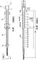
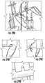
- FIG. 4 illustrates an ultrasonic horn 14, which is suitable for use with the above-described ultrasonic surgical apparatus for fragmenting and aspirating tissue.
- the ultrasonic horn has an external surface 120 and includes a first horn extender 14a, a second horn extender 14b extending distally from the first horn extender through a horn extender transition segment 112, and a third horn extender 14c extending distally from the second horn extender.
- the ultrasonic horn may have additional horn extender or extenders, or has only one or two horn extenders.
- the ultrasonic horn 14 has a distal end portion 113 and a threaded proximal end 111, a throughbore 117, a preaspiration hole or transverse bore 115, and a hexagon engagement portion 119.
- the ultrasonic horn has a larger external diameter in the first horn extender 14a section and a smaller external diameter in the second horn extender 14b section.
- the ultrasonic horn as shown is a stepped horn, it is known that there are ultrasonic horns that are not stepped.
- the ultrasonic horns can have a single long extender body, rather than two horn extenders of two different diameters, and the single long horn extender can have a constant external diameter throughout its length or have a gradually changing diameter along its length, for example, gradually decreasing in diameter along its length distally.
- additional extender or extenders may form additional steps or transition smoothly from another extender without forming any apparent step.
- the ultrasonic horn may vibrate in the ultrasonic frequency range with a longitudinal amplitude in excess of about 5 mils (0.005 inch; 0.127mm) to 14 mils (0.014 inch; 0.356mm).
- the throughbore 1 17 may also have a larger diameter section within the first horn extender 14a and a smaller diameter section within the second horn extender 14b section.
- the diameters of the proximal larger diameter and the distal smaller diameter portions of the throughbore may have any suitable diameters as can be readily determined as appropriate by those skilled in the art.
- the distal smaller diameter throughbore portion may be about 0.045 inches (1.143mm) in diameter.
- the throughbore does not necessarily have to correspond to the geometry of the ultrasonic horn extender or extenders.
- the throughbore may have two or more diameters in a stepped fashion or otherwise, a constant diameter throughout its length, or a gradually changing (for example, decreasing) diameter along its length distally.
- the ultrasonic horn 14 is substantially circular and disposed within the flue 16. During operation of the ultrasonic apparatus 10, irrigation fluid is supplied through the opening 17 into the flue 16. Flue 16 and the ultrasonic horn 14 define an annular cavity 36 therebetween. Irrigation fluid is supplied from flue 16 through cavity 36 to the distal end of the ultrasonic horn 14. A transverse bore is formed in preaspiration holes 1 15 near the distal end of the ultrasonic horn 14 and communicates with the throughbore 1 17. The irrigation fluid is drawn from preaspiration holes 1 15 and the surgical site into inlet 31 of the throughbore 1 17 along with fragmented tissue, blood, etc., and is removed from the surgical site via the throughbore 1 17 and the aspiration tube 24. The transverse bore provides an alternate route for fluid to enter throughbore 1 17 when inlet 31 becomes clogged.
- irrigation liquid for example saline
- This irrigation liquid is necessary to cool the surgical tip and site of tissue fragmentation.
- This irrigation liquid is provided to the flue with a peristaltic pump at a rate as low as 2 to 3 ml/min, which is typically only about a drip or two a second.
- the irrigation liquid is supplied at the proximal end of the ultrasonic horn.
- the irrigation liquid progresses to near the distal end of the ultrasonic horn, where two preaspiration holes of 0.015 inch (0.381mm) diameter suction a majority, perhaps 90-95%, of the irrigation through the holes connecting the outside horn diameter to the central suction channel.
- irrigation and suction supports a contiguous cooling circuit for the vibrating titanium metal and it also helps to wet effluent such as blood and tissue in the central channel. Some irrigation is also favorable to cooling the surgical site, improving coupling to tissue, and affording cavitation necessary to emulsification and aspiration of tissue, such as tumors.
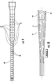
- the flue 16 is for use with an ultrasonic horn having an internal surface and an external surface and comprising a first horn extender and a second horn extender extending distally from the first horn extender and having a diameter smaller than the diameter of the first horn extender.
- the flue has an internal surface 51, an external surface 52, a proximal end 53 and distal end 54 and comprises a first flue extender 16a and a second flue extender 16b extending distally from the first flue extender and having a diameter smaller than the diameter of the first flue extender.
- the flue additional has a third flue extender 16c.
- the first and second flue extenders are configured to at least partially encase or surround the first and second horn extenders.
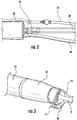
- FIG. 7A is another illustration of the flue 16 in accordance with the present invention
- FIG. 7B shows a prior art device.
- the existing flues on the market have sparse protrusion about the antinode, and near the node at the end of the surgical tip extender.
- This surgical tip utilizes a 60 durometer flexible silicone flue.
- the protrusions are located only over the large flue extender.
- the existing devices have protrusions only at the high motion lower-strain regions and are inadequate for protecting tissue external to the flue.
- CUSA® Excel Extended MicroTip Plus (EMT+) surgical tip (Integra LifeSciences Corporation, Plainsboro, NJ) and other CUSA Excel surgical tips employ silicone flues that do not utilized protrusions at high strain areas.
- the sparse protrusions can be spread under moderate loading on existing flues.
- Many existing extended surgical tips have protrusions on the internal diameter of their flues but only about the antinode, or point of greatest motion, of their horn extenders.
- a flue is often employed to deliver irrigation liquid and it protects tissue along the path to the surgical site from the vibrating surgical tip.
- the transducer vibrates along its length and stepped horns and specialty profiles of reduced diameter amplify vibration. It has been found in practice that sometimes a surgeon will compress the flue to tissue under high loading during vibration of the surgical tip causing thermal rise that can burn tissue.
- a surgical tip having a second horn extender of one-half wavelength which is of smaller diameter has greater motion than the large first horn extender due to greater mechanical gain. Compression of the flue to the vibrating surgical tip could cause thermal rise and thus has potential to create burns to the patient.
- Metal work heating may be experienced due to strain by bending a thin piece of metal or wire rod until it gets hot or until it breaks. The causes of such thermal rise have been identified, and the flues of the present invention address the identified issues to prevent such thermal rise.
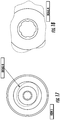
- the internal surface 51 of the second flue extender comprises a planar region 48 (that is planar as shown in the cross-sectional view of FIGS. 8A-8B , 9, and 10 ), or region between protrusions, and a plurality of protrusions 42 forming bridges 44, 46 that limits contact between the planar region 48 of the internal surface of second flue extender and the external surface of the second horn extender.
- the region 48 between the protrusions and/or inwardly projecting protrusions 42 of the internal surface 51 in a perspective view are generally cylindrical about the longitudinal axis L and may be a variety of shapes, sizes, relative positions, construction, and quantities and still be within the scope of the invention.
- the region 48 between protrusions 42 is arcuate.
- the region 48 may be a variety of shapes or contours.
- the protrusions are distributed at locations that correspond to locations on or near or about a node of the ultrasonic horn, on the first horn extender, the second horn extender and/or any additional horn extenders.
- the ultrasonic wave generated by the resonator has at least one node and at least one antinode.
- An antinode is a point of maximum displacement and a node is a point of minimum displacement in the wave.
- the protrusions form one or more bridges that limit contact between the planar region of the internal surface of the flue and the external surface of the ultrasonic horn.
- the flue may further comprise protrusions on its internal surface at locations that correspond to locations on or near or about an antinode of the ultrasonic horn, and/or at locations that correspond to locations of high strain gradient and motion, such as between nodes and antinodes of the ultrasonic horn.
- the internal surface of the second flue extender has protrusions.
- the internal surface may have at least 3 protrusions per square centimeter and preferably at least 5 protrusions per square centimeter.
- the protrusions may be present beyond the locations that correspond to the locations on or about one or more antinodes or beyond the greatest motion point on the ultrasonic horn, and preferably on substantially the entire internal surface of the flue corresponding to one or more horn extenders, for example, on the entire surface of the second flue extender, the entire surface of the first flue extender, and/or additional the entire surface of any additional flue extender(s).
- the large flue extender has at least 3 protrusions per square centimeter and the small flue extender has at least 5 protrusions per square centimeter.
- the protrusions are according to the invention present on the smaller flue extender in a higher density than those on the larger flue extender, but the protrusions on the smaller flue extender may be in the same density as those on the larger flue extender or even lower in density than those on the larger flue extender although it would seem unusual to have a lower density of protrusions on the small diameter flue extender than the larger diameter flue extender, as gain, strain, and motion is greater for the smaller flue extender of the horn.
- Flue 16 supplies irrigation fluid to an operative site during surgery. Since flue 16 is a hollow member, protrusions 42 are included for strength and may contact the ultrasonic horn. Protrusions 42 help maintain flue 16 and ultrasonic horn concentricity.
- the ultrasonic horn has a second horn extender of one-half wavelength which is of smaller diameter and has greater motion than the large first horn extender due to greater mechanical gain. The pattern, density, and region of protrusions have been improved. Protrusions are added as molded bumps to the second flue extender portion that corresponds to the second horn extender portion. Additionally, it has been learned that vibrational heating could occur at other high strain areas beyond the antinode, so the area with protrusions has been extended.
- protrusions in simple rows could be separated by compressing the flue with point or line loading, such that they spread and allow the thin wall of the silicone flue to compress to the vibrating tip. Consequently, the protrusions have been placed in a more complex pattern of greater density to aid in providing bridges to resist compression of the thin wall of the flue while allowing irrigation liquid to continue to flow beneath the bridges.
- Changing the complexity of the pattern, density and force needed to compress protrusions, and extending the region of protection of protrusions can greatly reduce thermal rise in compression, thereby reducing likelihood of burns of adjacent tissue protected by the flue.
- the pattern and density of protrusions have been improved, such that bridges are formed and sustained under high loads which keep the thin wall of the silicone flue from contacting the vibrating horn, and these bridges allow irrigation liquid to continue to flow.
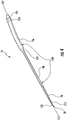
- the flue has generally the same shape as the ultrasonic horn with which the flue is used and is configured to position about the external surface of the ultrasonic horn, which may have no step or have one or more steps. Although it is shown that two flue extenders of different internal diameters form a stepped configuration, additional flue extender or extenders may form additional steps or transition smoothly from another extender without forming any apparent step.
- a flue may be provided for use with an ultrasonic horn that does not have stepped diameters.
- the flue may have a single elongated flue extender body, rather than two or more distinct flue extenders of two different diameters, and the single elongated flue extender may have a constant diameter throughout its length or have a gradually changing diameter along its length, for example, gradually decreasing in diameter along its length distally.
- the term "flue extender” may refer to a flue extender section of the elongated extender body, and the term “flue extenders” may refer to two or more flue extender sections that may not have any distinct transition point.
- the third flue extender 16c has six ribs 57 on the internal wall of the flue 16.
- the ribs 57 provide structural integrity to this section of the flue and allow it to be inserted around the surgical tip and allowing irrigation fluid to flow around the surgical tip to the distal end portion of the surgical tip.
- bridges 44, 46 are formed by the protrusions.
- the cylindrical surgical tip surface engages protrusions both longitudinally and axillary.
- the protrusions are distributed in staggered rows and columns such that one protrusion is centered about every four adjacent protrusions arranged in a substantially square or rectangular manner.
- the protrusions form longitudinal bridges 44 and also axial bridges 46.
- the cylindrical surface cannot fit between and spread the protrusions without causing increasing resistance and distribution of loading. Irrigation liquid can continue to find circuits under the multi-axis bridges.
- the protrusions on the flue may be in the form of spheres.
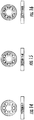
- the spherical radius of the protrusions on the first, larger flue extender is about 0.047 inches (1.194mm)
- the spherical radius of the protrusions on the second, smaller flue extender is about 0.028 inches (0.711mm).
- the spherical protrusions on the first flue extender all have the same size and the spherical protrusions on the second flue extender all have the same size, and the spherical protrusions of the first flue extender are larger than those on the second flue extender.
- the spheres may have different sizes than those shown in the exemplary embodiment, at least partly depending on the size of the ultrasonic horn and the designed strength of the flue.
- the spherical radius of the protrusions on the first, larger flue extender may be in the range of about 0.01 to about 0.10 inches (0.25 to about 25.4mm), or about 0.02 to about 0.08 inches (0.51mm to about 2.03mm), and the spherical radius of the protrusions on the second, smaller flue extender may be in the range of about 0.01 to about 0.08 inches (0.25mm to about 2.03mm), or about 0.01 to about 0.05 inches (0.25mm to about 1.27mm).
- the protrusions on the first flue extender are all identical in shape and size in this embodiment, but they do not need to be identical.
- the protrusions on the second flue extender are all identical in shape and size, but they do not need to be identical.
- the protrusions on the larger flue extender are preferably generally larger than those on the smaller flue extender, but the protrusions on the larger flue extender may be of the same size as those on the smaller flue extender or smaller than those on the smaller flue extender.
- the protrusions may have an average spherical diameter of about 0.02 to about 0.14 (about 0.5 mm to about 3.5 mm), preferably about 0.04 to about 0.12 inches (about 1.0 mm to about 3.0 mm).
- the protrusions on the larger flue extender may have an average diameter of about 0.09 to about 0.10 inches (about 2.2 mm to about 2.6 mm)
- the protrusions on the smaller flue extender may have an average diameter of about 0.05 to about 0.06 inches (about 1.2 mm to about 1.6 mm).
- the protrusions do not need to be in spherical form as shown and may have any suitable shapes and dimensions.
- the protrusions may have an average height in the range of about 0.01 (about 0.2mm) to about 0.10 inches (about 2.6mm), about 0.01 to about 0.06 inches (about 0.2 mm to about 1.5 mm), or about 0.01 to about 0.04 inches (about 0.2 mm to about 1.0 mm).
- the protrusions on the large flue extender may have an average height of 0.02 to about 0.06 inches (about 0.5 to about 1.5 mm) and those on the small flue extender may have an average height of 0.01 to about 0.03 inches (about 0.2 mm to about 0.8 mm).
- the protrusions do not have to be generally cylindrical or circular in cross-sections.
- the protrusions can be in any suitable geometry without departing from the scope of the present invention defined in the claims.
- the height, diameter and/or density of the protrusions do not have to be consistent across the entire internal surface of the flue or across the internal surface of a flue extender or any regions thereof.
- the bridges formed by the protrusions enable a path for irrigation liquid: it flows under the bridges.
- the density of protrusion can be increased to better support the smaller radius of the small flue extender, and the pattern can be adjusted to provide bridges both longitudinally and axially.
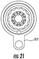
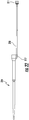
- FIGS. 20 and 21 show another embodiment of a flue 216 in accordance with the present invention.
- the flue has a flue tube connection section 217. As shown in FIG. 22 , the flue connects to a flue tube 218 at the flue tube connection section 217, for example, by molding or other methods known in the art.
- the flue tube 218 has a Luer fitting 21 1 for connection with an irrigation tube 22.
- the flue can be made of silicone, other elastomer or other suitable material.
- the flue tube can be made of silicone, other elastomer or other suitable material that is the same or different from the material of the flue.
- a thin walled silicone flue of about 0.01 to 0.05 inches (0.25mm to 1.27mm) in thickness may be used.
- a preferred material is silicone, such as silicone rubber compounds from Dow Corning. Silicone maintains integrity under catastrophic conditions such as loss of irrigation or clogging of the surgical tip. It is known that even traction or loading alone can damage nerves, and the silicone rubber provides some cushion relative to rigid flues. Silicone is rubber, and this material damps ultrasound that could propagate from the surgical tip to critical anatomy. Silicone, such as 60 Durometers, is flexible and conforms to curved surgical tips that provide clinical benefit in increased visualization under the surgeon's microscope. Other suitable materials known to those skilled in art may also be used to make the flue.
- Rigid flues made of materials such as polymethylpentene (PMP), acetal homopolymer resin (such as DuPont® Delrin® material), and polytetrafluoroethylene (PTFE) are also contemplated.
- PMP polymethylpentene
- acetal homopolymer resin such as DuPont® Delrin® material
- PTFE polytetrafluoroethylene
- rigid flues may experience problems such as cracking and melting under catastrophic circumstances, such as loss of irrigation or surgical tip clogging.
- Rigid flues, for example flues made of hard polymers may be more effective in distributing contact forces, thereby reducing concentrated frictional heating. The added stiffness from the increased durometer may help distribute the load more evenly, and therefore reduce the heating.
- rigid flues extend the useful range of surgical tips, such that the surgeon can steady or grip the flue of a longer surgical tip.
- rigid flues may not be suitable for curved tips, as the clearances and bend angles that would be needed obstruct the surgeon's line-of-sight to the distal end of the tip and surgical site.
- a flexible silicone material works better for these tips because it easily conforms to the shape of the tip and fits tightly against the tip, reducing the bulk of the design and providing the surgeon with a much better line-of-sight.
- the internal bumps also might help distribute the load more evenly to reduce heating while simultaneously creating a more uniform irrigation flow to help sink heat away.
- the flues in accordance with the present invention can be made by molding or other conventional manufacturing methods.
- the flues can be used with the existing ultrasonic surgical tips, such as CUSA Excel surgical tips, CUSA NXT 35 kHz extended length tip, or other ultrasonic surgical aspiration instruments on the market or being development.
- the surgical tips may be straight or curved, and may have different lengths or tip designs.
- the ultrasonic surgical apparatus comprising an ultrasonic horn and a flue in accordance with the present invention is useful for known applications of ultrasonic aspirators such as cranial-based surgery and when performing transsphenoidal or endoscopic-nasal approaches.
- Silicon flues were prototyped and tested in engineering bench studies and at a cadaver lab. Quantitative assessment in these studies shows the measureable improvement in reduce temperature under nominal, high, and excessive loading.
- the EMT Plus flue has a first horn extender, a second horn extender and a third horn extender.
- the second horn extender is referred to herein as an added horn extender or added extender
- the first horn extender is referred to as a conventional horn extender or a conventional extender.
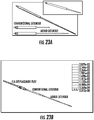
- FIGS. 23A-C Motion is modeled with Finite Element Analysis (FEA) and the results are shown in FIGS. 23A-C .
- the added extender has about 4 times the motion of the conventional extender.
- Titanium such as used in ultrasonic horns and aircraft, can withstand very high fatigue or cycling rates without breaking. Contacting regions of high strain with particle motion at ultrasonic frequencies, of say 25-50 kHz or 25,000 to 50,000 cycles per second, an extreme form of stretching on bending, can cause heating and conduct heat to the stationary flue.
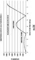
- High strain regions for EMT Plus are shown with FEA in FIG. 24 . It becomes clear the prior art devices where the protrusions are only at the high motion lower-strain regions are inadequate for protecting tissue external to the flue, if the flue is compressed to high strain regions. FEA reveals high strain regions. It was determine that elevated temperatures known to occur at motion maximum regions, or about antinodes, could also occur under flue compression to areas of high strain, particle motion.
- the new EMT+ flue was molded in Dow Corning Class VI Liquid Silicone Rubber Elastomer C6-560. This material is heat stable to 204°C, can be autoclaved, and has a tensile strength of 8.55 MPa after 8 hour post cure. The durometer hardness, Shore A, after post cure is 60. Its tear strength is 50.7 kN/m after post cure.
- the surgeon was asked to feel the achievable forces in the nasal passage, when constrained by the anatomy over the length of the Curved Extended MicroTip Plus and its flue.
- the surgeon was asked to force the handpiece and surgical tip outside of the cadaver with a load cell placed directly at the antinode of the small diameter extender, such that the force could be assessed corresponding to the surgeon's feel in the cadaver nasal passage.
- the surgeon was asked to load the flue and surgical tip to the degree expected in the nasal passage, even a maximum load. Then, the surgeon was asked to exert a force they felt was clearly excessive, such that this lateral load would not be expected.
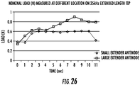
- FIGS. 25 and 26 show the normal load measured at different location on the tip under different forces.
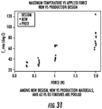
- the starting cadaver temperature was 19°C, and maximum temperature of the baseline commercial flue was quantified at 33.3°C at high load about the antinode of the small extender and 45.7°C at the high load of the large extender. It should be noted that the large extender would not normally be in the nasal passage in endonasal approaches, but could be inserted in some extended endonasal approaches. In this commercial flue, there were no protrusions in the small extended, and the large extender had lower density of protrusions. The temperature was then monitored with 60 durometer prototype flue with the improved pattern, density, and extended region of protrusions. The nominal to high loading by the surgeon's feel for the improved flue yielded 29.8 °C for the small extender and 24.6°C for the large extender.
- a variable load apparatus was used in conducting point load tests.
- the apparatus includes a custom wooden load cell attached. Load cell is normal to the flue surface, and is located at the antinode of the small extender. Thermocouple for temperature measurement is located between the wooden load cell and flue.
- the test procedure for 60 Durometer 35 kHz ELT Flues (Albright) is as follows: (1) Attach a 35 kHz Neuro test handpiece and 35 kHz Extended Length Test Tip to the CUSA NXT test console. Attach a 35 kHz Extended Length 60 Durometer Flue to the handpiece-tip assembly. (2) Attach a T-type thermocouple to the outside of the flue at the antinode region of the small extender.
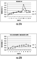
- FIGS. 28A (for a conventional flue) and 28B (for a flue according to the present invention) under point loading conditions, 60 durometer flues configured in accordance with the present invention exhibited greatly reduced temperatures with the protrusions of greater density and improved pattern. It was noted that it took greater than 30 seconds or more for maximum temperatures to be obtained. The flue would have to be compressed at a region yielding high temperatures at an excessive load for a prolonged period of time. Improvement was noted in reduced temperature with the improved protrusion pattern of greater density.
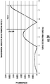
- a worst case test is performed, as shown in FIGS. 29A-D , with essentially a point load of a thermocouple surrounded by less thermally conductive material. Additionally, a static load is assumed in assessing temperature after a prolonged period, such as if the surgeon were to keep the surgical tip and flue in specific position for a significant amount of time. As shown in FIG. 30 , hot spots on the flue outside surface of maximum temperature with point load applied were previously probed. In this case, the maximum temperature was found to be beyond the antinode of the small extender. The hottest spot could be at maximum due to being beyond the greatest motion point and within a high strain gradient region. Further testing to associate this point with the strain gradient maxima may be performed. It is clear that the thermal maximum is beyond the antinode, and this discovery of hot spots at other than the antinode and implementation of the expanded region of greater density of protrusions is the principle of the present disclosure and improved design of new silicone flues.
- a reference to "A and/or B", when used in conjunction with open-ended language such as “comprising” can refer, in one embodiment, to A only (optionally including elements other than B); in another embodiment, to B only (optionally including elements other than A); in yet another embodiment, to both A and B (optionally including other elements); etc.
- the phrase "at least one,” in reference to a list of one or more elements, should be understood to mean at least one element selected from any one or more of the elements in the list of elements, but not necessarily including at least one of each and every element specifically listed within the list of elements and not excluding any combinations of elements in the list of elements.
- This definition also allows that elements may optionally be present other than the elements specifically identified within the list of elements to which the phrase "at least one" refers, whether related or unrelated to those elements specifically identified.
- At least one of A and B can refer, in one embodiment, to at least one, optionally including more than one, A, with no B present (and optionally including elements other than B); in another embodiment, to at least one, optionally including more than one, B, with no A present (and optionally including elements other than A); in yet another embodiment, to at least one, optionally including more than one, A, and at least one, optionally including more than one, B (and optionally including other elements); etc.
Applications Claiming Priority (3)
| Application Number | Priority Date | Filing Date | Title |
|---|---|---|---|
| US201662326988P | 2016-04-25 | 2016-04-25 | |
| US201662420691P | 2016-11-11 | 2016-11-11 | |
| PCT/IB2017/052382 WO2017187345A1 (en) | 2016-04-25 | 2017-04-25 | Flue for ultrasonic aspiration surgical horn |
Publications (2)
| Publication Number | Publication Date |
|---|---|
| EP3448283A1 EP3448283A1 (en) | 2019-03-06 |
| EP3448283B1 true EP3448283B1 (en) | 2020-02-26 |
Family
ID=58692542
Family Applications (1)
| Application Number | Title | Priority Date | Filing Date |
|---|---|---|---|
| EP17722514.1A Active EP3448283B1 (en) | 2016-04-25 | 2017-04-25 | Flue for ultrasonic aspiration surgical horn |
Country Status (8)
| Country | Link |
|---|---|
| US (3) | US11173327B2 (zh) |
| EP (1) | EP3448283B1 (zh) |
| JP (1) | JP6929301B2 (zh) |
| CN (1) | CN109328039B (zh) |
| AU (1) | AU2017257421B2 (zh) |
| CA (1) | CA3029756C (zh) |
| ES (1) | ES2781623T3 (zh) |
| WO (1) | WO2017187345A1 (zh) |
Cited By (1)
| Publication number | Priority date | Publication date | Assignee | Title |
|---|---|---|---|---|
| US11173327B2 (en) | 2016-04-25 | 2021-11-16 | Integra Lifesciences Enterprises, Lllp | Flue for ultrasonic aspiration surgical horn |
Families Citing this family (9)
| Publication number | Priority date | Publication date | Assignee | Title |
|---|---|---|---|---|
| USD820441S1 (en) | 2016-06-13 | 2018-06-12 | Integra Lifesciences Nr Ireland Limited | Surgical handpiece nosecone |
| ES2927744T3 (es) | 2016-05-24 | 2022-11-10 | Integra Lifesciences Entpr Lllp | Acoplamiento de tubo ergonómico para aparato médico |
| AU2017362062B2 (en) | 2016-11-16 | 2023-03-23 | Integra Lifesciences Enterprises, Lllp | Ultrasonic surgical handpiece |
| US10687840B1 (en) | 2016-11-17 | 2020-06-23 | Integra Lifesciences Nr Ireland Limited | Ultrasonic transducer tissue selectivity |
| CN107660196B (zh) * | 2017-08-07 | 2020-06-05 | 大族激光科技产业集团股份有限公司 | 非接触搬运装置 |
| USD911530S1 (en) | 2018-09-24 | 2021-02-23 | Stryker European Holdings I, Llc | Sleeve for ultrasonic handpiece |
| USD879289S1 (en) | 2018-09-24 | 2020-03-24 | Stryker Corporation | Tubing connector for a handheld surgical instrument |
| CN111265282B (zh) * | 2020-01-21 | 2021-07-16 | 江苏邦士医疗科技有限公司 | 超声手术手柄以及超声手术设备 |
| US20220125454A1 (en) * | 2020-10-23 | 2022-04-28 | Vicora, Inc. | Actuated thrombectomy device |
Family Cites Families (76)
| Publication number | Priority date | Publication date | Assignee | Title |
|---|---|---|---|---|
| US4063557A (en) | 1976-04-01 | 1977-12-20 | Cavitron Corporation | Ultrasonic aspirator |
| US4223676A (en) | 1977-12-19 | 1980-09-23 | Cavitron Corporation | Ultrasonic aspirator |
| US4425115A (en) | 1977-12-19 | 1984-01-10 | Wuchinich David G | Ultrasonic resonant vibrator |
| US4516398A (en) | 1980-10-08 | 1985-05-14 | Cooper Lasersonics, Inc. | Method of use of an ultrasonic surgical pre-aspirator having a orifice by-pass |
| US4921476A (en) | 1980-10-08 | 1990-05-01 | Cavitron, Inc. | Method for preventing clogging of a surgical aspirator |
| US4750902A (en) | 1985-08-28 | 1988-06-14 | Sonomed Technology, Inc. | Endoscopic ultrasonic aspirators |
| US4734964A (en) | 1985-10-24 | 1988-04-05 | Cooper Lasersonics, Inc. | Apparatus for refurbishing acoustic members |
| US4634419A (en) | 1985-12-13 | 1987-01-06 | Cooper Lasersonics, Inc. | Angulated ultrasonic surgical handpieces and method for their production |
| US4827911A (en) | 1986-04-02 | 1989-05-09 | Cooper Lasersonics, Inc. | Method and apparatus for ultrasonic surgical fragmentation and removal of tissue |
| US4747820A (en) | 1986-04-09 | 1988-05-31 | Cooper Lasersonics, Inc. | Irrigation/aspiration manifold and fittings for ultrasonic surgical aspiration system |
| US4846790A (en) * | 1986-04-09 | 1989-07-11 | Cooper Lasersonics, Inc. | Ultrasonic surgical system with irrigation manifold |
| US4768496A (en) | 1986-04-09 | 1988-09-06 | Cooper Lasersonics, Inc. | Handpiece interlock and logic control for ultrasonic surgical system |
| US4988334A (en) * | 1986-04-09 | 1991-01-29 | Valleylab, Inc. | Ultrasonic surgical system with aspiration tubulation connector |
| US4881761A (en) | 1986-04-09 | 1989-11-21 | Cooper Lasersonics, Inc. | Irrigation tubing connector for an ultrasonic surgical system |
| US5015227A (en) | 1987-09-30 | 1991-05-14 | Valleylab Inc. | Apparatus for providing enhanced tissue fragmentation and/or hemostasis |
| US4931047A (en) | 1987-09-30 | 1990-06-05 | Cavitron, Inc. | Method and apparatus for providing enhanced tissue fragmentation and/or hemostasis |
| JPH0194841A (ja) | 1987-10-08 | 1989-04-13 | Olympus Optical Co Ltd | 超音波処置具 |
| JPH0199547A (ja) | 1987-10-13 | 1989-04-18 | Olympus Optical Co Ltd | 超音波処置装置 |
| JPH02139615A (ja) | 1988-11-21 | 1990-05-29 | Toshiba Corp | 異種電源系回路を持つ電子機器 |
| US4978333A (en) | 1988-12-20 | 1990-12-18 | Valleylab, Inc. | Resonator for surgical handpiece |
| JPH0741450Y2 (ja) | 1989-04-26 | 1995-09-27 | オリンパス光学工業株式会社 | 超音波治療装置 |
| US5123903A (en) | 1989-08-10 | 1992-06-23 | Medical Products Development, Inc. | Disposable aspiration sleeve for ultrasonic lipectomy |
| US5492528A (en) | 1990-07-17 | 1996-02-20 | Anis; Azis Y. | Removal of tissue |
| US5221282A (en) | 1991-05-29 | 1993-06-22 | Sonokinetics Group | Tapered tip ultrasonic aspirator |
| US5190517A (en) | 1991-06-06 | 1993-03-02 | Valleylab Inc. | Electrosurgical and ultrasonic surgical system |
| US5188589A (en) | 1991-10-10 | 1993-02-23 | Alcon Surgical, Inc. | Textured irrigating sleeve |
| WO1993008750A2 (en) | 1991-11-04 | 1993-05-13 | Baxter International Inc. | Ultrasonic ablation device adapted for guidewire passage |
| EP0711611A3 (en) | 1992-02-07 | 1996-11-13 | Valleylab Inc | Control system for use in an ultrasonic surgical device |
| AU672227B2 (en) | 1992-11-30 | 1996-09-26 | Sherwood Services Ag | An ultrasonic surgical handpiece and an energy initiator to maintain the vibration and linear dynamics |
| US20020002369A1 (en) | 1993-08-23 | 2002-01-03 | Hood Larry L. | Method and apparatus for modifying visual acuity by moving a focal point of energy within a cornea |
| EP0737045A1 (en) | 1993-12-30 | 1996-10-16 | Valleylab, Inc. | Bipolar ultrasonic surgery |
| US5484398A (en) | 1994-03-17 | 1996-01-16 | Valleylab Inc. | Methods of making and using ultrasonic handpiece |
| USD367323S (en) | 1994-08-10 | 1996-02-20 | Linvatec Corporation | Surgical tubing cassette |
| US5466020A (en) | 1994-12-30 | 1995-11-14 | Valleylab Inc. | Bayonet connector for surgical handpiece |
| US5984904A (en) * | 1996-08-22 | 1999-11-16 | Bausch & Lomb Surgical, Inc. | Sleeve for a surgical instrument |
| US5897524A (en) | 1997-03-24 | 1999-04-27 | Wortrich; Theodore S. | Compact cassette for ophthalmic surgery |
| US6256859B1 (en) | 1998-09-25 | 2001-07-10 | Sherwood Services Ag | Method of manufacturing an aspiring tool |
| US6602227B1 (en) | 1998-09-25 | 2003-08-05 | Sherwood Services Ag | Surgical system console |
| USD438952S1 (en) | 1998-09-25 | 2001-03-13 | Sherwood Services Ag | Console for surgical procedures |
| US6214017B1 (en) | 1998-09-25 | 2001-04-10 | Sherwood Services Ag | Ultrasonic surgical apparatus |
| US6177755B1 (en) | 1999-10-22 | 2001-01-23 | Ben Hur | Air cooled ultrasonic apparatus |
| DE19960668C1 (de) | 1999-12-15 | 2001-08-16 | W O M Gmbh Physikalisch Medizi | Schlauchkasette für eine peristaltische Pumpe |
| US6499358B1 (en) | 1999-12-27 | 2002-12-31 | Sherwood Services Ag | Apparatus for applying a controlled amount of torque |
| US6595957B1 (en) | 2000-01-31 | 2003-07-22 | Ethicon, Inc. | Surgical fluid management system with a dampening chamber |
| US6723110B2 (en) | 2001-04-19 | 2004-04-20 | Synergetics, Inc. | High efficiency ultrasonic surgical aspiration tip |
| USD477867S1 (en) | 2002-04-03 | 2003-07-29 | Chf Solutions, Inc. | Tubing harness for extracorporeal treatment |
| USD479320S1 (en) | 2002-04-03 | 2003-09-02 | Chf Solutions, Inc. | Blood filter and tubing harness for extracorporeal blood treatment |
| AU2003265111A1 (en) | 2002-04-05 | 2003-11-17 | Misonix Incorporated | Electromechanical transducer with ergonomic shape |
| EP1539000A2 (en) | 2002-09-20 | 2005-06-15 | Sherwood Services AG | Electrosurgical instrument for fragmenting, cutting and coagulating tissue |
| US8100879B2 (en) | 2002-11-18 | 2012-01-24 | Nestec S.A. | Connector device for enteral administration set |
| US20060063973A1 (en) | 2004-04-21 | 2006-03-23 | Acclarent, Inc. | Methods and apparatus for treating disorders of the ear, nose and throat |
| US20050277897A1 (en) | 2004-06-14 | 2005-12-15 | Ghannoum Ziad R | Handpiece tip |
| US8092475B2 (en) | 2005-04-15 | 2012-01-10 | Integra Lifesciences (Ireland) Ltd. | Ultrasonic horn for removal of hard tissue |
| US8142460B2 (en) | 2005-04-15 | 2012-03-27 | Integra Lifesciences (Ireland) Ltd. | Bone abrading ultrasonic horns |
| US7871392B2 (en) | 2006-01-12 | 2011-01-18 | Integra Lifesciences (Ireland) Ltd. | Endoscopic ultrasonic surgical aspirator for use in fluid filled cavities |
| USD557804S1 (en) | 2006-11-09 | 2007-12-18 | Advanced Medical Optics, Inc. | Surgical cassette for a surgical system |
| USD557803S1 (en) | 2006-11-09 | 2007-12-18 | Advanced Medical Optics, Inc. | Surgical cassette for a surgical system |
| US20080200884A1 (en) | 2007-02-20 | 2008-08-21 | Perkins James T | Thin wall surgical irrigation tubing with longitudinal reinforcements |
| CN101322869B (zh) | 2007-06-14 | 2010-06-02 | 重庆融海超声医学工程研究中心有限公司 | 夹持式超声波治疗枪及含有该治疗枪的超声波美容治疗设备 |
| US8118823B2 (en) | 2008-06-12 | 2012-02-21 | Integra Lifesciences (Ireland) Ltd. | Shear stress ultrasonic horn for ultrasonic surgical aspiration |
| JP5941281B2 (ja) | 2008-11-17 | 2016-06-29 | バイトロナス, インコーポレイテッド | 体組織を切除するシステムおよび方法 |
| US8211103B2 (en) | 2009-04-24 | 2012-07-03 | Megadyne Medical Products, Inc. | Electrosurgical instrument with adjustable power cable |
| US8334635B2 (en) | 2009-06-24 | 2012-12-18 | Ethicon Endo-Surgery, Inc. | Transducer arrangements for ultrasonic surgical instruments |
| US9795404B2 (en) | 2009-12-31 | 2017-10-24 | Tenex Health, Inc. | System and method for minimally invasive ultrasonic musculoskeletal tissue treatment |
| USD675728S1 (en) | 2010-07-20 | 2013-02-05 | Kci Licensing, Inc. | Fluid-collection canister for reduced pressure treatment |
| US9149291B2 (en) | 2012-06-11 | 2015-10-06 | Tenex Health, Inc. | Systems and methods for tissue treatment |
| BR302013000587S1 (pt) | 2012-08-13 | 2014-06-17 | Storz Karl Gmbh & Co Kg | Configuração aplicada em dispositivo médico. |
| MX365199B (es) | 2013-02-27 | 2019-05-27 | B&G Plastics Inc | Conjunto de alojamiento de etiquetas para fijarse a un cuello de botella. |
| US9333114B2 (en) * | 2013-03-07 | 2016-05-10 | Fluidics Partners, Llc | Apparatus for performing phaco-emulsification |
| WO2014150526A1 (en) * | 2013-03-15 | 2014-09-25 | Misonix, Incorporated | Sheath coupling member and associated instrument assembly |
| US20150080925A1 (en) | 2013-09-19 | 2015-03-19 | Ethicon Endo-Surgery, Inc. | Alignment features for ultrasonic surgical instrument |
| MX2016005158A (es) | 2013-10-21 | 2016-08-17 | B&G Plastics Inc | Ensamble de alojamiento de etiqueta desprendible por consumidor para su fijacion a un cuello de botella. |
| US9962181B2 (en) * | 2014-09-02 | 2018-05-08 | Tenex Health, Inc. | Subcutaneous wound debridement |
| USD820441S1 (en) | 2016-06-13 | 2018-06-12 | Integra Lifesciences Nr Ireland Limited | Surgical handpiece nosecone |
| WO2017187345A1 (en) | 2016-04-25 | 2017-11-02 | Integra Lifesciences Nr Ireland Limited | Flue for ultrasonic aspiration surgical horn |
| ES2927744T3 (es) | 2016-05-24 | 2022-11-10 | Integra Lifesciences Entpr Lllp | Acoplamiento de tubo ergonómico para aparato médico |
-
2017
- 2017-04-25 WO PCT/IB2017/052382 patent/WO2017187345A1/en active Application Filing
- 2017-04-25 CN CN201780036141.0A patent/CN109328039B/zh active Active
- 2017-04-25 ES ES17722514T patent/ES2781623T3/es active Active
- 2017-04-25 AU AU2017257421A patent/AU2017257421B2/en active Active
- 2017-04-25 JP JP2018555560A patent/JP6929301B2/ja active Active
- 2017-04-25 EP EP17722514.1A patent/EP3448283B1/en active Active
- 2017-04-25 CA CA3029756A patent/CA3029756C/en active Active
- 2017-04-25 US US15/496,680 patent/US11173327B2/en active Active
-
2021
- 2021-11-15 US US17/526,193 patent/US11738215B2/en active Active
-
2023
- 2023-07-17 US US18/353,594 patent/US20240082606A1/en active Pending
Non-Patent Citations (1)
| Title |
|---|
| None * |
Cited By (2)
| Publication number | Priority date | Publication date | Assignee | Title |
|---|---|---|---|---|
| US11173327B2 (en) | 2016-04-25 | 2021-11-16 | Integra Lifesciences Enterprises, Lllp | Flue for ultrasonic aspiration surgical horn |
| US11738215B2 (en) | 2016-04-25 | 2023-08-29 | Integra LifeSciences Enterprises, LLP | Flue for ultrasonic aspiration surgical horn |
Also Published As
| Publication number | Publication date |
|---|---|
| US11738215B2 (en) | 2023-08-29 |
| AU2017257421A1 (en) | 2018-11-08 |
| US20220072339A1 (en) | 2022-03-10 |
| EP3448283A1 (en) | 2019-03-06 |
| CN109328039B (zh) | 2022-02-22 |
| US11173327B2 (en) | 2021-11-16 |
| WO2017187345A1 (en) | 2017-11-02 |
| JP6929301B2 (ja) | 2021-09-01 |
| ES2781623T3 (es) | 2020-09-03 |
| US20240082606A1 (en) | 2024-03-14 |
| US20170304655A1 (en) | 2017-10-26 |
| CA3029756A1 (en) | 2017-11-02 |
| JP2019514501A (ja) | 2019-06-06 |
| CN109328039A (zh) | 2019-02-12 |
| CA3029756C (en) | 2023-10-31 |
| AU2017257421B2 (en) | 2021-05-13 |
Similar Documents
| Publication | Publication Date | Title |
|---|---|---|
| US11738215B2 (en) | Flue for ultrasonic aspiration surgical horn | |
| JP4429160B2 (ja) | 人間工学的形状を有した高効率医療変換器。 | |
| US8518066B2 (en) | Method of applying shear stress | |
| US20210022763A1 (en) | Linear ultrasonic shear stress cutting blade | |
| US10736686B2 (en) | Surgical device employing a cantilevered beam dissector | |
| US11752035B2 (en) | Ultrasonic needles and transducer assemblies formed of non-metal materials or a combination of materials | |
| US20230363785A1 (en) | Flue for Ultrasonic Aspiration Surgical Horn | |
| EP3000424B1 (en) | Ultrasonic treatment device |
Legal Events
| Date | Code | Title | Description |
|---|---|---|---|
| STAA | Information on the status of an ep patent application or granted ep patent |
Free format text: STATUS: UNKNOWN |
|
| STAA | Information on the status of an ep patent application or granted ep patent |
Free format text: STATUS: THE INTERNATIONAL PUBLICATION HAS BEEN MADE |
|
| PUAI | Public reference made under article 153(3) epc to a published international application that has entered the european phase |
Free format text: ORIGINAL CODE: 0009012 |
|
| STAA | Information on the status of an ep patent application or granted ep patent |
Free format text: STATUS: REQUEST FOR EXAMINATION WAS MADE |
|
| 17P | Request for examination filed |
Effective date: 20181015 |
|
| AK | Designated contracting states |
Kind code of ref document: A1 Designated state(s): AL AT BE BG CH CY CZ DE DK EE ES FI FR GB GR HR HU IE IS IT LI LT LU LV MC MK MT NL NO PL PT RO RS SE SI SK SM TR |
|
| AX | Request for extension of the european patent |
Extension state: BA ME |
|
| DAV | Request for validation of the european patent (deleted) | ||
| DAX | Request for extension of the european patent (deleted) | ||
| GRAP | Despatch of communication of intention to grant a patent |
Free format text: ORIGINAL CODE: EPIDOSNIGR1 |
|
| STAA | Information on the status of an ep patent application or granted ep patent |
Free format text: STATUS: GRANT OF PATENT IS INTENDED |
|
| INTG | Intention to grant announced |
Effective date: 20190920 |
|
| GRAS | Grant fee paid |
Free format text: ORIGINAL CODE: EPIDOSNIGR3 |
|
| GRAA | (expected) grant |
Free format text: ORIGINAL CODE: 0009210 |
|
| STAA | Information on the status of an ep patent application or granted ep patent |
Free format text: STATUS: THE PATENT HAS BEEN GRANTED |
|
| AK | Designated contracting states |
Kind code of ref document: B1 Designated state(s): AL AT BE BG CH CY CZ DE DK EE ES FI FR GB GR HR HU IE IS IT LI LT LU LV MC MK MT NL NO PL PT RO RS SE SI SK SM TR |
|
| REG | Reference to a national code |
Ref country code: GB Ref legal event code: FG4D |
|
| REG | Reference to a national code |
Ref country code: CH Ref legal event code: EP |
|
| REG | Reference to a national code |
Ref country code: AT Ref legal event code: REF Ref document number: 1236700 Country of ref document: AT Kind code of ref document: T Effective date: 20200315 |
|
| REG | Reference to a national code |
Ref country code: IE Ref legal event code: FG4D |
|
| REG | Reference to a national code |
Ref country code: DE Ref legal event code: R096 Ref document number: 602017012310 Country of ref document: DE |
|
| PG25 | Lapsed in a contracting state [announced via postgrant information from national office to epo] |
Ref country code: RS Free format text: LAPSE BECAUSE OF FAILURE TO SUBMIT A TRANSLATION OF THE DESCRIPTION OR TO PAY THE FEE WITHIN THE PRESCRIBED TIME-LIMIT Effective date: 20200226 Ref country code: FI Free format text: LAPSE BECAUSE OF FAILURE TO SUBMIT A TRANSLATION OF THE DESCRIPTION OR TO PAY THE FEE WITHIN THE PRESCRIBED TIME-LIMIT Effective date: 20200226 Ref country code: NO Free format text: LAPSE BECAUSE OF FAILURE TO SUBMIT A TRANSLATION OF THE DESCRIPTION OR TO PAY THE FEE WITHIN THE PRESCRIBED TIME-LIMIT Effective date: 20200526 |
|
| REG | Reference to a national code |
Ref country code: NL Ref legal event code: MP Effective date: 20200226 |
|
| REG | Reference to a national code |
Ref country code: LT Ref legal event code: MG4D |
|
| PG25 | Lapsed in a contracting state [announced via postgrant information from national office to epo] |
Ref country code: SE Free format text: LAPSE BECAUSE OF FAILURE TO SUBMIT A TRANSLATION OF THE DESCRIPTION OR TO PAY THE FEE WITHIN THE PRESCRIBED TIME-LIMIT Effective date: 20200226 Ref country code: IS Free format text: LAPSE BECAUSE OF FAILURE TO SUBMIT A TRANSLATION OF THE DESCRIPTION OR TO PAY THE FEE WITHIN THE PRESCRIBED TIME-LIMIT Effective date: 20200626 Ref country code: LV Free format text: LAPSE BECAUSE OF FAILURE TO SUBMIT A TRANSLATION OF THE DESCRIPTION OR TO PAY THE FEE WITHIN THE PRESCRIBED TIME-LIMIT Effective date: 20200226 Ref country code: GR Free format text: LAPSE BECAUSE OF FAILURE TO SUBMIT A TRANSLATION OF THE DESCRIPTION OR TO PAY THE FEE WITHIN THE PRESCRIBED TIME-LIMIT Effective date: 20200527 Ref country code: BG Free format text: LAPSE BECAUSE OF FAILURE TO SUBMIT A TRANSLATION OF THE DESCRIPTION OR TO PAY THE FEE WITHIN THE PRESCRIBED TIME-LIMIT Effective date: 20200526 Ref country code: HR Free format text: LAPSE BECAUSE OF FAILURE TO SUBMIT A TRANSLATION OF THE DESCRIPTION OR TO PAY THE FEE WITHIN THE PRESCRIBED TIME-LIMIT Effective date: 20200226 |
|
| REG | Reference to a national code |
Ref country code: ES Ref legal event code: FG2A Ref document number: 2781623 Country of ref document: ES Kind code of ref document: T3 Effective date: 20200903 |
|
| PG25 | Lapsed in a contracting state [announced via postgrant information from national office to epo] |
Ref country code: NL Free format text: LAPSE BECAUSE OF FAILURE TO SUBMIT A TRANSLATION OF THE DESCRIPTION OR TO PAY THE FEE WITHIN THE PRESCRIBED TIME-LIMIT Effective date: 20200226 |
|
| PG25 | Lapsed in a contracting state [announced via postgrant information from national office to epo] |
Ref country code: SM Free format text: LAPSE BECAUSE OF FAILURE TO SUBMIT A TRANSLATION OF THE DESCRIPTION OR TO PAY THE FEE WITHIN THE PRESCRIBED TIME-LIMIT Effective date: 20200226 Ref country code: LT Free format text: LAPSE BECAUSE OF FAILURE TO SUBMIT A TRANSLATION OF THE DESCRIPTION OR TO PAY THE FEE WITHIN THE PRESCRIBED TIME-LIMIT Effective date: 20200226 Ref country code: PT Free format text: LAPSE BECAUSE OF FAILURE TO SUBMIT A TRANSLATION OF THE DESCRIPTION OR TO PAY THE FEE WITHIN THE PRESCRIBED TIME-LIMIT Effective date: 20200719 Ref country code: SK Free format text: LAPSE BECAUSE OF FAILURE TO SUBMIT A TRANSLATION OF THE DESCRIPTION OR TO PAY THE FEE WITHIN THE PRESCRIBED TIME-LIMIT Effective date: 20200226 Ref country code: CZ Free format text: LAPSE BECAUSE OF FAILURE TO SUBMIT A TRANSLATION OF THE DESCRIPTION OR TO PAY THE FEE WITHIN THE PRESCRIBED TIME-LIMIT Effective date: 20200226 Ref country code: RO Free format text: LAPSE BECAUSE OF FAILURE TO SUBMIT A TRANSLATION OF THE DESCRIPTION OR TO PAY THE FEE WITHIN THE PRESCRIBED TIME-LIMIT Effective date: 20200226 Ref country code: DK Free format text: LAPSE BECAUSE OF FAILURE TO SUBMIT A TRANSLATION OF THE DESCRIPTION OR TO PAY THE FEE WITHIN THE PRESCRIBED TIME-LIMIT Effective date: 20200226 Ref country code: EE Free format text: LAPSE BECAUSE OF FAILURE TO SUBMIT A TRANSLATION OF THE DESCRIPTION OR TO PAY THE FEE WITHIN THE PRESCRIBED TIME-LIMIT Effective date: 20200226 |
|
| REG | Reference to a national code |
Ref country code: AT Ref legal event code: MK05 Ref document number: 1236700 Country of ref document: AT Kind code of ref document: T Effective date: 20200226 |
|
| REG | Reference to a national code |
Ref country code: DE Ref legal event code: R097 Ref document number: 602017012310 Country of ref document: DE |
|
| PG25 | Lapsed in a contracting state [announced via postgrant information from national office to epo] |
Ref country code: MC Free format text: LAPSE BECAUSE OF FAILURE TO SUBMIT A TRANSLATION OF THE DESCRIPTION OR TO PAY THE FEE WITHIN THE PRESCRIBED TIME-LIMIT Effective date: 20200226 |
|
| REG | Reference to a national code |
Ref country code: CH Ref legal event code: PL |
|
| PLBE | No opposition filed within time limit |
Free format text: ORIGINAL CODE: 0009261 |
|
| STAA | Information on the status of an ep patent application or granted ep patent |
Free format text: STATUS: NO OPPOSITION FILED WITHIN TIME LIMIT |
|
| PG25 | Lapsed in a contracting state [announced via postgrant information from national office to epo] |
Ref country code: LU Free format text: LAPSE BECAUSE OF NON-PAYMENT OF DUE FEES Effective date: 20200425 Ref country code: AT Free format text: LAPSE BECAUSE OF FAILURE TO SUBMIT A TRANSLATION OF THE DESCRIPTION OR TO PAY THE FEE WITHIN THE PRESCRIBED TIME-LIMIT Effective date: 20200226 Ref country code: LI Free format text: LAPSE BECAUSE OF NON-PAYMENT OF DUE FEES Effective date: 20200430 Ref country code: CH Free format text: LAPSE BECAUSE OF NON-PAYMENT OF DUE FEES Effective date: 20200430 |
|
| 26N | No opposition filed |
Effective date: 20201127 |
|
| REG | Reference to a national code |
Ref country code: BE Ref legal event code: MM Effective date: 20200430 |
|
| PG25 | Lapsed in a contracting state [announced via postgrant information from national office to epo] |
Ref country code: SI Free format text: LAPSE BECAUSE OF FAILURE TO SUBMIT A TRANSLATION OF THE DESCRIPTION OR TO PAY THE FEE WITHIN THE PRESCRIBED TIME-LIMIT Effective date: 20200226 Ref country code: PL Free format text: LAPSE BECAUSE OF FAILURE TO SUBMIT A TRANSLATION OF THE DESCRIPTION OR TO PAY THE FEE WITHIN THE PRESCRIBED TIME-LIMIT Effective date: 20200226 Ref country code: BE Free format text: LAPSE BECAUSE OF NON-PAYMENT OF DUE FEES Effective date: 20200430 |
|
| REG | Reference to a national code |
Ref country code: DE Ref legal event code: R081 Ref document number: 602017012310 Country of ref document: DE Owner name: INTEGRA LIFESCIENCES ENTERPRISES, LLLP (NACH D, US Free format text: FORMER OWNER: INTEGRA LIFESCIENCES NR IRELAND LTD., DUBLIN, IE |
|
| REG | Reference to a national code |
Ref country code: GB Ref legal event code: 732E Free format text: REGISTERED BETWEEN 20210603 AND 20210609 |
|
| REG | Reference to a national code |
Ref country code: ES Ref legal event code: PC2A Owner name: INTEGRA LIFESCIENCES ENTERPRISES, LLLP Effective date: 20210826 |
|
| PG25 | Lapsed in a contracting state [announced via postgrant information from national office to epo] |
Ref country code: TR Free format text: LAPSE BECAUSE OF FAILURE TO SUBMIT A TRANSLATION OF THE DESCRIPTION OR TO PAY THE FEE WITHIN THE PRESCRIBED TIME-LIMIT Effective date: 20200226 Ref country code: MT Free format text: LAPSE BECAUSE OF FAILURE TO SUBMIT A TRANSLATION OF THE DESCRIPTION OR TO PAY THE FEE WITHIN THE PRESCRIBED TIME-LIMIT Effective date: 20200226 Ref country code: CY Free format text: LAPSE BECAUSE OF FAILURE TO SUBMIT A TRANSLATION OF THE DESCRIPTION OR TO PAY THE FEE WITHIN THE PRESCRIBED TIME-LIMIT Effective date: 20200226 |
|
| PG25 | Lapsed in a contracting state [announced via postgrant information from national office to epo] |
Ref country code: MK Free format text: LAPSE BECAUSE OF FAILURE TO SUBMIT A TRANSLATION OF THE DESCRIPTION OR TO PAY THE FEE WITHIN THE PRESCRIBED TIME-LIMIT Effective date: 20200226 Ref country code: AL Free format text: LAPSE BECAUSE OF FAILURE TO SUBMIT A TRANSLATION OF THE DESCRIPTION OR TO PAY THE FEE WITHIN THE PRESCRIBED TIME-LIMIT Effective date: 20200226 |
|
| PGFP | Annual fee paid to national office [announced via postgrant information from national office to epo] |
Ref country code: IE Payment date: 20230223 Year of fee payment: 7 Ref country code: FR Payment date: 20230309 Year of fee payment: 7 |
|
| PGFP | Annual fee paid to national office [announced via postgrant information from national office to epo] |
Ref country code: IT Payment date: 20230310 Year of fee payment: 7 Ref country code: GB Payment date: 20230302 Year of fee payment: 7 |
|
| P01 | Opt-out of the competence of the unified patent court (upc) registered |
Effective date: 20230518 |
|
| PGFP | Annual fee paid to national office [announced via postgrant information from national office to epo] |
Ref country code: ES Payment date: 20230510 Year of fee payment: 7 Ref country code: DE Payment date: 20230228 Year of fee payment: 7 |
|
| PGFP | Annual fee paid to national office [announced via postgrant information from national office to epo] |
Ref country code: IE Payment date: 20240223 Year of fee payment: 8 |