EP3447605A1 - Display linking system - Google Patents
Display linking system Download PDFInfo
- Publication number
- EP3447605A1 EP3447605A1 EP18181735.4A EP18181735A EP3447605A1 EP 3447605 A1 EP3447605 A1 EP 3447605A1 EP 18181735 A EP18181735 A EP 18181735A EP 3447605 A1 EP3447605 A1 EP 3447605A1
- Authority
- EP
- European Patent Office
- Prior art keywords
- display
- display data
- hmd
- region
- long
- Prior art date
- Legal status (The legal status is an assumption and is not a legal conclusion. Google has not performed a legal analysis and makes no representation as to the accuracy of the status listed.)
- Withdrawn
Links
Images


Classifications
-
- G—PHYSICS
- G06—COMPUTING OR CALCULATING; COUNTING
- G06F—ELECTRIC DIGITAL DATA PROCESSING
- G06F3/00—Input arrangements for transferring data to be processed into a form capable of being handled by the computer; Output arrangements for transferring data from processing unit to output unit, e.g. interface arrangements
- G06F3/01—Input arrangements or combined input and output arrangements for interaction between user and computer
- G06F3/03—Arrangements for converting the position or the displacement of a member into a coded form
- G06F3/041—Digitisers, e.g. for touch screens or touch pads, characterised by the transducing means
-
- H—ELECTRICITY
- H04—ELECTRIC COMMUNICATION TECHNIQUE
- H04M—TELEPHONIC COMMUNICATION
- H04M1/00—Substation equipment, e.g. for use by subscribers
- H04M1/02—Constructional features of telephone sets
- H04M1/0202—Portable telephone sets, e.g. cordless phones, mobile phones or bar type handsets
- H04M1/026—Details of the structure or mounting of specific components
- H04M1/0266—Details of the structure or mounting of specific components for a display module assembly
-
- G—PHYSICS
- G06—COMPUTING OR CALCULATING; COUNTING
- G06F—ELECTRIC DIGITAL DATA PROCESSING
- G06F1/00—Details not covered by groups G06F3/00 - G06F13/00 and G06F21/00
- G06F1/16—Constructional details or arrangements
- G06F1/1613—Constructional details or arrangements for portable computers
- G06F1/163—Wearable computers, e.g. on a belt
-
- G—PHYSICS
- G02—OPTICS
- G02B—OPTICAL ELEMENTS, SYSTEMS OR APPARATUS
- G02B27/00—Optical systems or apparatus not provided for by any of the groups G02B1/00 - G02B26/00, G02B30/00
- G02B27/01—Head-up displays
- G02B27/017—Head mounted
-
- G—PHYSICS
- G06—COMPUTING OR CALCULATING; COUNTING
- G06F—ELECTRIC DIGITAL DATA PROCESSING
- G06F1/00—Details not covered by groups G06F3/00 - G06F13/00 and G06F21/00
- G06F1/16—Constructional details or arrangements
- G06F1/1613—Constructional details or arrangements for portable computers
- G06F1/1626—Constructional details or arrangements for portable computers with a single-body enclosure integrating a flat display, e.g. Personal Digital Assistants [PDAs]
-
- G—PHYSICS
- G06—COMPUTING OR CALCULATING; COUNTING
- G06F—ELECTRIC DIGITAL DATA PROCESSING
- G06F3/00—Input arrangements for transferring data to be processed into a form capable of being handled by the computer; Output arrangements for transferring data from processing unit to output unit, e.g. interface arrangements
- G06F3/01—Input arrangements or combined input and output arrangements for interaction between user and computer
- G06F3/048—Interaction techniques based on graphical user interfaces [GUI]
- G06F3/0481—Interaction techniques based on graphical user interfaces [GUI] based on specific properties of the displayed interaction object or a metaphor-based environment, e.g. interaction with desktop elements like windows or icons, or assisted by a cursor's changing behaviour or appearance
- G06F3/0482—Interaction with lists of selectable items, e.g. menus
-
- G—PHYSICS
- G06—COMPUTING OR CALCULATING; COUNTING
- G06F—ELECTRIC DIGITAL DATA PROCESSING
- G06F3/00—Input arrangements for transferring data to be processed into a form capable of being handled by the computer; Output arrangements for transferring data from processing unit to output unit, e.g. interface arrangements
- G06F3/01—Input arrangements or combined input and output arrangements for interaction between user and computer
- G06F3/048—Interaction techniques based on graphical user interfaces [GUI]
- G06F3/0487—Interaction techniques based on graphical user interfaces [GUI] using specific features provided by the input device, e.g. functions controlled by the rotation of a mouse with dual sensing arrangements, or of the nature of the input device, e.g. tap gestures based on pressure sensed by a digitiser
- G06F3/0488—Interaction techniques based on graphical user interfaces [GUI] using specific features provided by the input device, e.g. functions controlled by the rotation of a mouse with dual sensing arrangements, or of the nature of the input device, e.g. tap gestures based on pressure sensed by a digitiser using a touch-screen or digitiser, e.g. input of commands through traced gestures
- G06F3/04883—Interaction techniques based on graphical user interfaces [GUI] using specific features provided by the input device, e.g. functions controlled by the rotation of a mouse with dual sensing arrangements, or of the nature of the input device, e.g. tap gestures based on pressure sensed by a digitiser using a touch-screen or digitiser, e.g. input of commands through traced gestures for inputting data by handwriting, e.g. gesture or text
-
- G—PHYSICS
- G06—COMPUTING OR CALCULATING; COUNTING
- G06F—ELECTRIC DIGITAL DATA PROCESSING
- G06F3/00—Input arrangements for transferring data to be processed into a form capable of being handled by the computer; Output arrangements for transferring data from processing unit to output unit, e.g. interface arrangements
- G06F3/01—Input arrangements or combined input and output arrangements for interaction between user and computer
- G06F3/048—Interaction techniques based on graphical user interfaces [GUI]
- G06F3/0487—Interaction techniques based on graphical user interfaces [GUI] using specific features provided by the input device, e.g. functions controlled by the rotation of a mouse with dual sensing arrangements, or of the nature of the input device, e.g. tap gestures based on pressure sensed by a digitiser
- G06F3/0488—Interaction techniques based on graphical user interfaces [GUI] using specific features provided by the input device, e.g. functions controlled by the rotation of a mouse with dual sensing arrangements, or of the nature of the input device, e.g. tap gestures based on pressure sensed by a digitiser using a touch-screen or digitiser, e.g. input of commands through traced gestures
- G06F3/04886—Interaction techniques based on graphical user interfaces [GUI] using specific features provided by the input device, e.g. functions controlled by the rotation of a mouse with dual sensing arrangements, or of the nature of the input device, e.g. tap gestures based on pressure sensed by a digitiser using a touch-screen or digitiser, e.g. input of commands through traced gestures by partitioning the display area of the touch-screen or the surface of the digitising tablet into independently controllable areas, e.g. virtual keyboards or menus
-
- H—ELECTRICITY
- H04—ELECTRIC COMMUNICATION TECHNIQUE
- H04B—TRANSMISSION
- H04B1/00—Details of transmission systems, not covered by a single one of groups H04B3/00 - H04B13/00; Details of transmission systems not characterised by the medium used for transmission
- H04B1/38—Transceivers, i.e. devices in which transmitter and receiver form a structural unit and in which at least one part is used for functions of transmitting and receiving
- H04B1/3827—Portable transceivers
- H04B1/385—Transceivers carried on the body, e.g. in helmets
-
- H—ELECTRICITY
- H04—ELECTRIC COMMUNICATION TECHNIQUE
- H04M—TELEPHONIC COMMUNICATION
- H04M1/00—Substation equipment, e.g. for use by subscribers
- H04M1/72—Mobile telephones; Cordless telephones, i.e. devices for establishing wireless links to base stations without route selection
- H04M1/724—User interfaces specially adapted for cordless or mobile telephones
- H04M1/72403—User interfaces specially adapted for cordless or mobile telephones with means for local support of applications that increase the functionality
- H04M1/72409—User interfaces specially adapted for cordless or mobile telephones with means for local support of applications that increase the functionality by interfacing with external accessories
- H04M1/72412—User interfaces specially adapted for cordless or mobile telephones with means for local support of applications that increase the functionality by interfacing with external accessories using two-way short-range wireless interfaces
-
- G—PHYSICS
- G06—COMPUTING OR CALCULATING; COUNTING
- G06F—ELECTRIC DIGITAL DATA PROCESSING
- G06F2200/00—Indexing scheme relating to G06F1/04 - G06F1/32
- G06F2200/16—Indexing scheme relating to G06F1/16 - G06F1/18
- G06F2200/161—Indexing scheme relating to constructional details of the monitor
- G06F2200/1614—Image rotation following screen orientation, e.g. switching from landscape to portrait mode
-
- G—PHYSICS
- G06—COMPUTING OR CALCULATING; COUNTING
- G06F—ELECTRIC DIGITAL DATA PROCESSING
- G06F2203/00—Indexing scheme relating to G06F3/00 - G06F3/048
- G06F2203/048—Indexing scheme relating to G06F3/048
- G06F2203/04803—Split screen, i.e. subdividing the display area or the window area into separate subareas
-
- H—ELECTRICITY
- H04—ELECTRIC COMMUNICATION TECHNIQUE
- H04B—TRANSMISSION
- H04B1/00—Details of transmission systems, not covered by a single one of groups H04B3/00 - H04B13/00; Details of transmission systems not characterised by the medium used for transmission
- H04B1/38—Transceivers, i.e. devices in which transmitter and receiver form a structural unit and in which at least one part is used for functions of transmitting and receiving
- H04B1/3827—Portable transceivers
- H04B1/385—Transceivers carried on the body, e.g. in helmets
- H04B2001/3866—Transceivers carried on the body, e.g. in helmets carried on the head
-
- H—ELECTRICITY
- H04—ELECTRIC COMMUNICATION TECHNIQUE
- H04M—TELEPHONIC COMMUNICATION
- H04M2250/00—Details of telephonic subscriber devices
- H04M2250/22—Details of telephonic subscriber devices including a touch pad, a touch sensor or a touch detector
Definitions
- the invention relates to a display linking system that links equipment having a display function such as a smartphone to a head-mounted display for a display.
- a touchscreen display is adopted for equipment such as a smartphone, and a user performs an operation by touching a screen.
- equipment such as a smartphone
- a head-mounted display HMD
- the smartphone screen can be displayed on the HMD.
- the user can perform the operation on the smartphone screen and can check the screen on the HMD.
- JP-B-5630141 it is described that a part of the smartphone screen is selected and a selected area of the screen is displayed on the HMD. The part of the smartphone screen is selected by the user.
- FIG. 20 a holder 210 (a shaded portion in the drawing) that is attached to a personal digital assistant (PDA) 200 is disclosed.
- FIG. 19 shows a circuit block thereof.
- An HMD 220 is connected to the holder 210. Not display data from the PDA 200 but display data from a flash memory card 212 that is attached to the holder 210 is displayed on this HMD 220.
- FIG. 20 shows a display example on the HMD 220.
- the display data recorded in the flash memory card 212 is displayed ("ABC" in the drawing).
- a cursor 222 and display switching buttons 226, 228 for the operation are displayed.
- a liquid crystal panel 202 of the PDA 200 that is accommodated in the holder 210 functions not as a display but as a touchpad used to move the cursor 222. That is, the cursor 222 on the HMD 220 can be moved by a stylus 201.
- a display mode is changed to that shown in FIG. 21 .
- the display switching button 226 is clicked, the liquid crystal panel 202 of the PDA 200 is divided into an upper region 202a and a lower region 202b.
- the display data for the HMD 220 which is recorded in the flash memory 212 in the holder 210, is compressed for the liquid crystal panel 202 of the PDA 200.
- the compressed display data is displayed in the upper region 202a of the PDA 200.
- a virtual keyboard is displayed in the lower region 202b of the PDA 200. It is described that not only the display data recorded in the flash memory 212 but also input data from the virtual keyboard are displayed in the upper region 202a. However, specific processing is not described.
- liquid crystal panel 202 of the PDA 200 can be linked to the HMD 220 for the display.
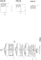
- FIG. 22A shows the smartphone screen data
- FIG. 22B shows screen data output from the smartphone. Because the smartphone screen is vertically long and the HMD screen is horizontally long, a shaded portion in FIG. 22B corresponds to the smartphone screen data.
- JP5630141 B a difference in the screen configuration as described above is not considered, and thus there is a possibility that the appropriate linked display cannot be realized.
- the part of the screen that is selected on the smartphone by the user is displayed on the HMD, it is impossible to acknowledge which part of the screen is selected in advance.
- the display data is not generated on the PDA 200 side, and the display data recorded in the flash memory card 212 in the holder 210 is displayed on the HMD 220. In addition, this display data is compressed for the crystal panel 202 and displayed on the PDA 200.
- JP2003279881A does not achieve the display on the HMD 220 on the basis of the display data generated on the PDA side or the smartphone side.
- such linking is not assumed that the processing is executed by using capacities of the PDA, the smartphone, and the like and the part of the crystal panel 202 showing the processing result is displayed on the HMD 220. That is, there is a problem that a display linking system sufficiently using the capacities of the PDA and the smartphone cannot be provided.
- the invention has purposes of solving problems as described above and providing a system capable of an appropriate linked display in consideration of a difference in screen configuration between a smartphone and an HMD.
- the invention also has a purpose of providing a system that facilitates development of a smartphone application by using a processing capacity of a smartphone or the like and causing a predetermined part of a screen showing the processing result to be displayed on an HMD.
- the invention further has a purpose of providing a system capable of recognizing a command properly when the command is provided by speech input.
- the invention has a purpose of providing a system that solves at least one of the above problems.
- step S11 and step S31 in the embodiments correspond to the "image direction fixing means".
- the "input/output port 24" in the embodiments correspond to the "output section”.
- Step S32 in the embodiments corresponds to the "initial image output means".
- Steps S42, S43 in the embodiments correspond to the "conversion procedure establishment means".
- Step S2 in the embodiment corresponds to the "conversion means".
- a "program” is a concept that includes not only a program directly executable by a CPU but also a source program, a compressed program, an encrypted program, and the like.
- FIG. 1 is a functional block diagram of a display linking system according to one embodiment of the invention.
- a smartphone 2 as a mobile terminal includes a touch display 22 that allows touch input.
- the smartphone 2 includes an acceleration sensor (not shown) that detects a direction of gravity, and switches between vertically-long image data (image data in an appropriate direction that is displayed when a screen is vertically long) and horizontally-long image data (image data in the appropriate direction that is displayed when the screen is horizontally long) for the display in accordance with a direction of the screen.
- the smartphone 2 is fixed by an image direction fixing means 21 to a mode in which vertically-long image data 23 is displayed regardless of the direction of the screen.
- the vertically-long image data 23 is changed to horizontally-long output image data 31 and is then output from an input/output port 24.
- a central portion 33 of the horizontally-long output image data 31 corresponds to the vertically-long image data 23.
- a part of the vertically-long image data 23 (in this example, one third thereof on an upper side) is an overlapping display region 25.
- This overlapping display region 25 is a region that is displayed on a head-mounted display (HMD) 6.
- a converter 4 receives the horizontally-long output image data 31 and identifies the central portion 33 that corresponds to the vertically-long image data 23. Furthermore, the converter 4 extracts an overlapping display region 35 from this central portion 33, the overlapping display region 35 corresponding to the overlapping display region 25 of the vertically-long image data 23. The converter 4 outputs data on the extracted overlapping display region 35 as HMD display data 41 for the HMD 6. The HMD 6 displays the received HMD display data 41.
- a processing program is described under a precondition that the overlapping display region 25, which is displayed on the touch display 22, is also displayed on the HMD 6 while a lower region 27 is only displayed on the smartphone 2. For example, when an operation button or the like is displayed in the lower region 27, command input or the like can be made by operating this.
- the processing program is also described such that a processing result and the like are displayed in the overlapping display region 25.
- the HMD display data 41 which has the same contents as that displayed in the overlapping display region 25, is displayed on the HMD 6.
- a user can perform an operation on the touch display 22 of the smartphone 2 and displays an operation result on the HMD 6.
- FIG. 2 shows a system configuration of the display linking system according to the one embodiment of the invention.
- This system includes the smartphone 2, the converter 4, and the head-mounted display (HMD) 6.
- HMD head-mounted display
- a cable 52 is connected to a connector terminal (an input/output port 24) of the smartphone 2 via a connector 50.
- the cable 52 is connected to an input port 47 of the converter 4.
- Output of the converter 4 is received by the HMD 6.
- picoLinker® of WESTUNITIS CO., LTD. can be used as the HMD 6.
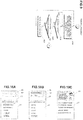
- FIG. 3 shows a hardware configuration of the smartphone 2.
- Memory 26, the touch display 22, non-volatile memory 28, the input/output port 24, a communication circuit 30, a microphone 37, and a speaker 39 are connected to a CPU 20. Note that a talking circuit and the like are not shown in FIG. 3 .
- the touch display 22 displays the image data and receives the user's input.
- the input/output port 24 is a port that at least output the output image data.
- a Lightning® connector of an iPhone® corresponds thereto.
- a micro USB connector of an Android® terminal corresponds thereto.
- the communication circuit 30 communicates with the Internet.
- the microphone 37 acquires the user's operation as voice.
- the speaker 39 outputs an instruction and the like to the user.
- a terminal program 32 is installed on the non-volatile memory 28. This terminal program 32 is downloaded from a website on the Internet via the communication circuit 30.
- FIG. 4 shows a hardware configuration of the converter 4.
- Memory 42, non-volatile memory 44, an HDMI converter 46, and an output port 48 are connected to a CPU 40.
- the HMD 6 is connected to the output port 48.
- the cable 52 is connected to the HDMI converter 46 via the input/output port 47. Accordingly, the output image data from the smartphone 2 is converted to HDMI data and loaded onto the converter 4.
- a conversion program 50 is recorded in the non-volatile memory 44.
- a battery for driving the converter 4 is provided.
- the smartphone 2 has the vertical screen, and an upper region of the touch display 22 is set as the overlapping display region 25.
- This overlapping display region 25 is a region for the display. Only this overlapping display region 25 is displayed in an entire display region 7 ( FIG. 5B ) of the HMD 6.
- the lower region 27 of the touch display 22 is a region for the display and the operation input. This lower region 27 is not displayed on the HMD 6.
- the application of the smartphone 2 displays the contents to be displayed on the HMD 6 in the predetermined overlapping display region 25 and displays the contents that should only be displayed on the smartphone 2 in the lower region 27.
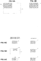
- FIG. 6 is a flowchart of the conversion program 50 in the converter 4.
- the CPU 40 in the converter 4 retrieves the HDMI data, to which the output image data received from the input/output port 47 is converted (step S1).
- FIG. 7A shows the image data that is displayed on the touch display 22 of the smartphone 2.
- a shaded portion is a portion that is set as the overlapping display region 25.
- FIG. 7B shows that the output image data, which is output from the input/output port 24 of the smartphone 2, is converted to the HDMI data.
- the CPU 40 records the retrieved HDMI data in the memory 42 (a buffer) (step S1).
- the CPU 40 identifies and extracts the overlapping display region 35 from the central portion 33 of the horizontally-long HDMI data (step S2).
- the overlapping display region 25 in the image data 23 of the smartphone 2, which is shown in FIG. 7A is defined in advance.
- a conversion ratio of the vertically-long image data in FIG. 7A to the horizontally-long HDMI data in FIG. 7B is known. Accordingly, the CPU 40 can identify the overlapping display region 35 from the central portion 33 in FIG. 7B .
- the CPU 40 outputs the thus-extracted data on the overlapping display region 35 as the HMD display data 41 from the output port 48 (step S3).
- the CPU 40 executes image data extraction processing; however, an FPGA or the like may partially or entirely execute the image data extraction processing.
- FIG. 8 is a flowchart of the terminal program 32.
- the CPU 20 in the smartphone 2 turns off a vertical/horizontal automatic switching function of the touch display 22 and fixes the touch display 22 in a vertical screen mode (step S11).
- the smartphone 2 has a function of detecting posture of the smartphone 2 by using a sensor that detects gravitational acceleration (not shown) and switching between the vertical screen mode and a horizontal screen mode.
- this switching function is turned off, and the touch display 22 is fixed to the vertical screen mode regardless of the posture of the smartphone 2. This is done for a purpose of fixing the output image data because the output image data that is output from the input/output port 24 in the vertical screen mode differs from the output image data that is output from the input/output port 24 in the horizontal screen mode.
- the CPU 20 displays a product input field 60 and a model input field 62 in the overlapping display region 25 and displays a list of products, one of which should be input in the product input field 60, in the lower region 27 (step S12).
- the product input field 60 and the model input field 62 are displayed on the HMD 6.
- the user operates the touch display 22 and selects a work target product as from the lower region 27 (step S13).
- the CPU 20 displays a selected product name in the product input field 60 and displays a list of models, one of which should be input in the model input field 62, in the lower region 27 (step S14).
- a display example is shown in FIG. 10B .
- the user operates the touch display 22 and selects a work target model from the lower region 27 (step S15).
- the CPU 20 displays a work content selection screen as shown in FIG. 10C for the product and the model (step S16).
- FIG. 11 shows the work content selection screen in detail.
- a selection region 258 in which a work content is selected is displayed in the overlapping display region 25.
- the work content of the confirmed product "AUTOMOBILE” and the confirmed model “K-120” is displayed.
- the candidate work content “ENGINE ROOM MAINTENANCE” is displayed.
- "ENGINE ROOM MAINTENANCE" is selected and confirmed as the work content.
- the microphone 37 catches this user's speech, and the CPU 20 recognizes this as the confirmation command by a speech analysis (speech-to-text).
- the command may be input by a method other than voice input such as pressing of the operation button.
- an "UP” command or a “DOWN” command is input by voice.
- "UP” command is input in a state shown in FIG. 11
- "BRAKE MAINTENANCE” hiding on a lower side of "ENGINE ROOM MAINTENANCE” is positioned in the central portion and becomes the candidate.
- "DOWN” command is input, "UNDERBODY MAINTENANCE” hiding on an upper side of "ENGINE ROOM MAINTENANCE” is positioned in the central portion and becomes the candidate.
- the commands are displayed in a possible command display region 256 of the overlapping display region 25.
- “UP”, “DOWN”, “CONFIRM”, “CAMERA”, and “WORK DONE” are displayed. That is, in this screen, only these voice commands are accepted. Acceptable voice commands are prepared for each of the screens.
- the user who inputs the command by voice can understand that the commands displayed in the possible command display region 256 are only accepted, and thus the user can say the correct command.
- the commands that can be input in the screen are narrowed, speech recognition by the CPU 20 is facilitated.
- the possible command display region 256 is provided in the overlapping display region 25, the possible command display region 256 is also displayed on the HMD 6. Thus, the user can easily check the commands.
- FIG. 11 shows that the "CONFIRM" command is recognized.
- a speech waveform window 252 is provided in the overlapping display region 25.
- the CPU 20 converts the speech received from the microphone 37 to a digital signal and displays the digital signal as a speech waveform 253 in this speech waveform window 252.
- a required voice level for the speech recognition is also displayed as a line 255.
- the line 255 is provided to indicate the required voice level for the correct speech recognition. Accordingly, when the user says the command, the user looks at the speech waveform 253 and can adjust the voice level such that the voice level exceeds the line 255.
- the CPU 20 displays a list of the work contents in the lower region 27. Because the lower region 27 is larger than the overlapping display region 25, the longer list of the work contents than that in the overlapping display region 25 can be displayed in the lower region 27. However, the lower region 27 is only displayed on the smartphone 2.
- the user looks at the screen on the HMD 6 and determines the work content by the speech (step S17). Note that the selection of the work content in steps S16, S17 may be performed plural times (in plural hierarchies).
- the CPU 20 displays a list of processes in the determined work content in the lower region 27, and also displays a work instruction screen that shows a work instruction "CHECK **" and an image 259 prepared in advance for a work target part in the overlapping display region 25 (step S18). Furthermore, the CPU 20 outputs the instruction content as the speech from the speaker 39.
- FIG. 12 shows the work instruction screen.
- the user receives this work instruction and performs the work with reference to the image 259 that shows the work part and the work content.
- This image is displayed on the HMD 6.
- Process numbers 257 in this work content are shown at a bottom of the image 259, and only the current process number is enlarged.
- FIG. 12 while the process numbers "1" to "5" are displayed, only “1” is enlarged, and thus it is indicated that the current process is numbered as "1".
- a cycle time 261 is displayed at a lower right corner.
- the cycle time is a processing time of the process.
- the denominator of the cycle time is set in advance, and the numerator indicates a time spent to the present time. In the drawing, 3/11 is shown, and it is indicated that 3 seconds have elapsed from the initiation of this process that is planned to be completed in 11 seconds.
- the user inputs the speech command.
- the current process is the checking process.
- the speech command of "GOOD” is input.
- the result of the check is NG, the speech command of "PROBLEM PRESENT” or the like is input (step S19). In the example shown in FIG. 12 , "GOOD" is input.
- the CPU 20 records this input result in a manner that this input result corresponds to the process.
- the CPU 20 also records the cycle time.
- the CPU 20 determines whether there is an unprocessed process of the selected work (step S20). If the unprocessed process is present, the processing proceeds to the next step, and the processing in step S18 onward is repeated (step S21).
- FIG. 13 shows a next process screen.
- the process number "2" is enlarged.
- the completed work process is displayed with a tick.
- the rest of the screen is the same as that in FIG. 12 .
- the user can perform the operation by the speech while looking at the screen on the HMD 6.
- the user can concentrate on the work in a hand-free condition.
- step S16 When the process number "5" is completed, the processing returns to step S16, and the CPU 20 selects another work (steps S16, S17).
- the work can be assisted by using the smartphone 2 and the HMD 6.
- the CPU 20 records the work result (whether each of the processes is OK or NG, the cycle time, and the like) in the non-volatile memory 28.
- the first embodiment it is recognized in advance what type of the output image data is output from the input/output port 24 of the smartphone 2.
- the output image data differs depending on models of the smartphone 2.
- the overlapping display region 25 is not correctly displayed on the HMD 6 depending on the models.
- initial setting is performed during activation of the terminal program 32. In this way, even when the output image data differs depending on the models as described above, correct display linking is realized.
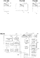
- FIG. 16 is a functional block diagram of a display linking system according to a second embodiment of the invention.
- the smartphone 2 as the mobile terminal includes the touch display 22 that allows touch input.
- the smartphone 2 includes the acceleration sensor (not shown) that detects the direction of gravity, and switches between the vertically-long image data and the horizontally-long image data for the display in accordance with the direction of the screen.
- An initial image output means 202 displays an initial image on the touch display 22.
- the overlapping display region 25 can be identified in accordance with the direction of the current image.
- an initial image 23 is displayed as shown in FIG. 16 .
- the overlapping display region 25 is colored with gray, an outer frame thereof is surrounded by bold lines, and the lower region 27 is colored with white.
- output image data 31 as shown in the drawing is output from the input/output port 24, for example.
- the image direction fixing means 21 fixes an image direction in the mode at the time when the above initial image is output.
- a conversion procedure establishment means 402 in the converter 4 receives the output image data 31 and recognizes the grayed overlapping display region 35, which is surrounded by the bold lines, therefrom. For example, the conversion procedure establishment means 402 identifies coordinates (X1, Y1) at an upper left corner and coordinates (X2, Y2) at a lower right corner of the overlapping display region 35 with an upper left corner of the output image data 31 being an origin (0, 0). Here, one pixel is set as a unit of the coordinates. Furthermore, the conversion procedure establishment means 402 records the coordinates (X1, Y1) at the upper left corner and the coordinates (X2, Y2) at the lower right corner as information for clipping the overlapping display region 35. In this way, the initial setting is ended.
- the converter 4 transmits a fact that the initial setting is ended to the smartphone 2.
- the smartphone 2 executes the processing by the terminal program 32.
- the processing at this time onward is the same as that in the first embodiment.
- the conversion procedure is automatically established in accordance with the mode of the output image data 31, which depends on the model.
- the appropriate display linking can be realized.
- the system configuration is the same as that shown in FIG. 2 .
- the hardware configuration of the smartphone 2 is the same as that shown in FIG. 3 .
- a speech recognition program is installed on the non-volatile memory 28. The speech recognition program recognizes the speech input through the microphone 37 as the text and identifies an instruction command.
- the hardware configuration of the converter 4 is the same as that shown in FIG. 4 .
- initial setting processing is executed when the terminal program 32 is activated.
- This initial setting processing may be a part of the terminal program 32 or may separately be provided from the terminal program 32.
- FIG. 17 is a flowchart during the initial setting of the terminal program 32 and the conversion program 50.
- the CPU 20 in the smartphone 2 (hereinafter may be abbreviated as the smartphone 2) first turns off the vertical/horizontal automatic switching function and fixes the touch display 22 in the current screen mode (step S31).
- the CPU 20 in the smartphone 2 fixes the touch display 22 in the vertical screen mode when the current screen mode is the vertical screen mode, and is fixed in the horizontal screen mode when the current screen mode is the horizontal screen mode.
- FIG. 18A displays an example of the initial image 23 that is displayed on the touch display 22.
- the initial image 23 is configured to include the overlapping display region 25 and the lower region 27.
- the lower region 27 is white, and the overlapping display region 25 is gray.
- a region line 251 is drawn from the upper left corner to the lower right corner of the overlapping display region 25.
- the display linking with the HMD 6 can correctly be realized.
- the CPU 40 in the converter 4 determines whether the output image data 31 of the initial screen is received (step S41). Once receiving the output image data 31, the converter 4 recognizes the overlapping display region 35 from the output image data 31 (step S42).
- the converter 4 finds the gray region and acquires coordinates at an upper left end and a lower right end of the region line 251 drawn therein.
- the coordinates at the upper left corner of the output image data 31 is set to (0, 0), and the one pixel is set as one coordinate element. Then, the coordinates are calculated.
- the coordinates at the lower right corner is (1080, 1920).
- the upper left corner (0, 640) and the lower right corner (160, 1280) are extracted as a position of the overlapping display region 35.
- FIG. 18C the lower right coordinates of the output image data 31 are (1920, 1080)
- the upper left end (0, 0) and the lower right end (640, 1080) of the region line 251 are extracted as the position of the overlapping display region 35.
- the position of the overlapping display region 35 can be identified by the coordinates of the upper left end and the lower right end of the region line 251.
- the position of the overlapping display region 35 is indicated by the coordinates with the one pixel being the one unit.
- the position of the overlapping display region 35 may be indicated by normalized coordinates of the overlapping display region 35.
- the converter 4 records the coordinates (the upper left corner, the lower right corner) of the overlapping display region 35, which are extracted as described above, in the non-volatile memory 44 (step S43). Accordingly, in the processing onward, the converter 4 clips the overlapping display region 35 on the basis of these coordinates and generates the HMD display data 41.
- the converter 4 sends notice of the termination of the initial setting to the smartphone 2 via the cable 52 (step S44).
- the smartphone 2 executes the following processing (for example, the processing in FIG. 8 (except for step S11)).
Landscapes
- Engineering & Computer Science (AREA)
- Theoretical Computer Science (AREA)
- General Engineering & Computer Science (AREA)
- Human Computer Interaction (AREA)
- Physics & Mathematics (AREA)
- General Physics & Mathematics (AREA)
- Computer Networks & Wireless Communication (AREA)
- Computer Hardware Design (AREA)
- Signal Processing (AREA)
- Optics & Photonics (AREA)
- Controls And Circuits For Display Device (AREA)
- User Interface Of Digital Computer (AREA)
- Telephone Function (AREA)
- Devices For Indicating Variable Information By Combining Individual Elements (AREA)
Applications Claiming Priority (1)
| Application Number | Priority Date | Filing Date | Title |
|---|---|---|---|
| JP2017158655A JP2019036914A (ja) | 2017-08-21 | 2017-08-21 | 連携表示システム |
Publications (1)
| Publication Number | Publication Date |
|---|---|
| EP3447605A1 true EP3447605A1 (en) | 2019-02-27 |
Family
ID=62873267
Family Applications (1)
| Application Number | Title | Priority Date | Filing Date |
|---|---|---|---|
| EP18181735.4A Withdrawn EP3447605A1 (en) | 2017-08-21 | 2018-07-04 | Display linking system |
Country Status (4)
| Country | Link |
|---|---|
| US (1) | US20190056813A1 (https=) |
| EP (1) | EP3447605A1 (https=) |
| JP (1) | JP2019036914A (https=) |
| CN (1) | CN109428956A (https=) |
Cited By (1)
| Publication number | Priority date | Publication date | Assignee | Title |
|---|---|---|---|---|
| CN110248026A (zh) * | 2019-06-18 | 2019-09-17 | 北京字节跳动网络技术有限公司 | 一种移动终端、显示系统及其显示控制方法、记录介质 |
Families Citing this family (8)
| Publication number | Priority date | Publication date | Assignee | Title |
|---|---|---|---|---|
| US10237509B1 (en) * | 2016-08-05 | 2019-03-19 | Apple Inc. | Systems with keyboards and head-mounted displays |
| JP2021105783A (ja) | 2019-12-26 | 2021-07-26 | セイコーエプソン株式会社 | 表示システム、表示方法、及び、プログラム |
| JP2021105782A (ja) * | 2019-12-26 | 2021-07-26 | セイコーエプソン株式会社 | 表示システム、表示方法、及び、プログラム |
| JP2021119431A (ja) | 2020-01-30 | 2021-08-12 | セイコーエプソン株式会社 | 表示システム、コントローラー、表示システムの制御方法およびプログラム |
| JP2021119364A (ja) | 2020-01-30 | 2021-08-12 | セイコーエプソン株式会社 | 表示装置、表示装置の制御方法およびプログラム |
| US11829527B2 (en) | 2020-11-30 | 2023-11-28 | Samsung Electronics Co., Ltd. | Augmented reality device, electronic device interacting with augmented reality device, and controlling method thereof |
| JP7581075B2 (ja) | 2021-02-18 | 2024-11-12 | キヤノン株式会社 | メガネ型情報機器、その方法及びプログラム |
| CN119604927A (zh) * | 2022-08-09 | 2025-03-11 | 麦克赛尔株式会社 | 协同显示系统以及协同显示方法 |
Citations (7)
| Publication number | Priority date | Publication date | Assignee | Title |
|---|---|---|---|---|
| JPS5630141B2 (https=) | 1974-01-31 | 1981-07-13 | ||
| JP2003279881A (ja) | 2002-03-27 | 2003-10-02 | Hitachi Ltd | 携帯情報装置 |
| US20110285646A1 (en) * | 2010-05-19 | 2011-11-24 | Hon Hai Precision Industry Co., Ltd. | Electronic device with touch pad |
| US20130002701A1 (en) * | 2010-08-18 | 2013-01-03 | Brother Kogyo Kabushiki Kaisha | Systems for displaying images on portable display devices and head-mountable displays, methods for controlling such systems, and computer-readable storage media storing instructions for controlling such systems |
| US20130288753A1 (en) * | 2012-04-25 | 2013-10-31 | Kopin Corporation | Headset Computer (HSC) As Auxiliary Display With ASR and HT Input |
| US8717285B1 (en) * | 2009-10-28 | 2014-05-06 | Amazon Technologies, Inc. | Orientation lock |
| US20170235435A1 (en) * | 2016-02-16 | 2017-08-17 | Samsung Electronics Co., Ltd. | Electronic device and method of application data display therefor |
Family Cites Families (11)
| Publication number | Priority date | Publication date | Assignee | Title |
|---|---|---|---|---|
| US20050228281A1 (en) * | 2004-03-31 | 2005-10-13 | Nefos Thomas P | Handheld diagnostic ultrasound system with head mounted display |
| US8754931B2 (en) * | 2010-01-08 | 2014-06-17 | Kopin Corporation | Video eyewear for smart phone games |
| AU2011205223C1 (en) * | 2011-08-09 | 2013-03-28 | Microsoft Technology Licensing, Llc | Physical interaction with virtual objects for DRM |
| US20130100167A1 (en) * | 2011-10-20 | 2013-04-25 | Nokia Corporation | Method and apparatus for control of orientation of information presented based upon device use state |
| JP6008086B2 (ja) * | 2012-03-26 | 2016-10-19 | セイコーエプソン株式会社 | 頭部装着型表示装置 |
| US9398344B2 (en) * | 2012-06-08 | 2016-07-19 | Lg Electronics Inc. | Image display apparatus, mobile terminal and method for operating the same |
| JP2015227919A (ja) * | 2014-05-30 | 2015-12-17 | セイコーエプソン株式会社 | 画像表示装置、画像表示装置を制御する方法、コンピュータープログラム、および、画像表示システム |
| JP2015125567A (ja) * | 2013-12-26 | 2015-07-06 | 株式会社東芝 | 電子機器、方法及びプログラム |
| US10102674B2 (en) * | 2015-03-09 | 2018-10-16 | Google Llc | Virtual reality headset connected to a mobile computing device |
| US10264297B1 (en) * | 2017-09-13 | 2019-04-16 | Perfect Sense, Inc. | Time-based content synchronization |
| US10217488B1 (en) * | 2017-12-15 | 2019-02-26 | Snap Inc. | Spherical video editing |
-
2017
- 2017-08-21 JP JP2017158655A patent/JP2019036914A/ja active Pending
-
2018
- 2018-06-28 US US16/021,412 patent/US20190056813A1/en not_active Abandoned
- 2018-07-04 EP EP18181735.4A patent/EP3447605A1/en not_active Withdrawn
- 2018-08-03 CN CN201810875362.3A patent/CN109428956A/zh active Pending
Patent Citations (7)
| Publication number | Priority date | Publication date | Assignee | Title |
|---|---|---|---|---|
| JPS5630141B2 (https=) | 1974-01-31 | 1981-07-13 | ||
| JP2003279881A (ja) | 2002-03-27 | 2003-10-02 | Hitachi Ltd | 携帯情報装置 |
| US8717285B1 (en) * | 2009-10-28 | 2014-05-06 | Amazon Technologies, Inc. | Orientation lock |
| US20110285646A1 (en) * | 2010-05-19 | 2011-11-24 | Hon Hai Precision Industry Co., Ltd. | Electronic device with touch pad |
| US20130002701A1 (en) * | 2010-08-18 | 2013-01-03 | Brother Kogyo Kabushiki Kaisha | Systems for displaying images on portable display devices and head-mountable displays, methods for controlling such systems, and computer-readable storage media storing instructions for controlling such systems |
| US20130288753A1 (en) * | 2012-04-25 | 2013-10-31 | Kopin Corporation | Headset Computer (HSC) As Auxiliary Display With ASR and HT Input |
| US20170235435A1 (en) * | 2016-02-16 | 2017-08-17 | Samsung Electronics Co., Ltd. | Electronic device and method of application data display therefor |
Cited By (1)
| Publication number | Priority date | Publication date | Assignee | Title |
|---|---|---|---|---|
| CN110248026A (zh) * | 2019-06-18 | 2019-09-17 | 北京字节跳动网络技术有限公司 | 一种移动终端、显示系统及其显示控制方法、记录介质 |
Also Published As
| Publication number | Publication date |
|---|---|
| CN109428956A (zh) | 2019-03-05 |
| JP2019036914A (ja) | 2019-03-07 |
| US20190056813A1 (en) | 2019-02-21 |
Similar Documents
| Publication | Publication Date | Title |
|---|---|---|
| EP3447605A1 (en) | Display linking system | |
| US8914163B2 (en) | System and method for incorporating gesture and voice recognition into a single system | |
| EP2778865B1 (en) | Input control method and electronic device supporting the same | |
| US20080114604A1 (en) | Method and system for a user interface using higher order commands | |
| EP3239975A1 (en) | Information processing device, information processing method, and program | |
| JP2005509973A (ja) | ジェスチャに基づくユーザインタフェース用の方法及び装置 | |
| CN101901050A (zh) | 输入装置 | |
| CN104360736A (zh) | 基于手势的终端控制方法和系统 | |
| KR101502064B1 (ko) | 터치 입력 처리 시스템 및 방법 | |
| US20190129517A1 (en) | Remote control by way of sequences of keyboard codes | |
| CN111433735A (zh) | 实现通用硬件-软件接口的方法、设备和计算机可读介质 | |
| CN117396365A (zh) | 对话服务装置和对话系统控制方法 | |
| CN117666794A (zh) | 车辆交互方法、装置、电子设备及存储介质 | |
| KR20140127146A (ko) | 디스플레이 장치 및 그의 제어 방법 | |
| WO2016131181A1 (zh) | 一种指纹事件的处理方法、装置及终端 | |
| CN107784211A (zh) | 密码验证方法及装置 | |
| KR20150014139A (ko) | 화면 정보 제공 방법 및 장치 | |
| US20100223548A1 (en) | Method for introducing interaction pattern and application functionalities | |
| JP6447474B2 (ja) | 電子機器 | |
| CN117396956A (zh) | 显示控制装置和显示控制方法 | |
| KR20150055498A (ko) | 제스쳐를 이용한 단말 제어 방법 및 장치 | |
| JP4765893B2 (ja) | タッチパネル搭載装置、外部装置、及び外部装置の操作方法 | |
| JP2016062071A (ja) | 電子機器、方法およびプログラム | |
| JP6672399B2 (ja) | 電子機器 | |
| KR100809965B1 (ko) | 원격 자원 액세스 및 인터페이스 장치 |
Legal Events
| Date | Code | Title | Description |
|---|---|---|---|
| PUAI | Public reference made under article 153(3) epc to a published international application that has entered the european phase |
Free format text: ORIGINAL CODE: 0009012 |
|
| STAA | Information on the status of an ep patent application or granted ep patent |
Free format text: STATUS: THE APPLICATION HAS BEEN PUBLISHED |
|
| AK | Designated contracting states |
Kind code of ref document: A1 Designated state(s): AL AT BE BG CH CY CZ DE DK EE ES FI FR GB GR HR HU IE IS IT LI LT LU LV MC MK MT NL NO PL PT RO RS SE SI SK SM TR |
|
| AX | Request for extension of the european patent |
Extension state: BA ME |
|
| STAA | Information on the status of an ep patent application or granted ep patent |
Free format text: STATUS: THE APPLICATION IS DEEMED TO BE WITHDRAWN |
|
| 18D | Application deemed to be withdrawn |
Effective date: 20190828 |