EP3447414A1 - Kühl- und/oder gefriergerät - Google Patents
Kühl- und/oder gefriergerät Download PDFInfo
- Publication number
- EP3447414A1 EP3447414A1 EP18189982.4A EP18189982A EP3447414A1 EP 3447414 A1 EP3447414 A1 EP 3447414A1 EP 18189982 A EP18189982 A EP 18189982A EP 3447414 A1 EP3447414 A1 EP 3447414A1
- Authority
- EP
- European Patent Office
- Prior art keywords
- evaporator
- section
- device body
- refrigerator
- unit carrier
- Prior art date
- Legal status (The legal status is an assumption and is not a legal conclusion. Google has not performed a legal analysis and makes no representation as to the accuracy of the status listed.)
- Granted
Links
Images

Classifications
-
- F—MECHANICAL ENGINEERING; LIGHTING; HEATING; WEAPONS; BLASTING
- F25—REFRIGERATION OR COOLING; COMBINED HEATING AND REFRIGERATION SYSTEMS; HEAT PUMP SYSTEMS; MANUFACTURE OR STORAGE OF ICE; LIQUEFACTION SOLIDIFICATION OF GASES
- F25D—REFRIGERATORS; COLD ROOMS; ICE-BOXES; COOLING OR FREEZING APPARATUS NOT OTHERWISE PROVIDED FOR
- F25D23/00—General constructional features
- F25D23/006—General constructional features for mounting refrigerating machinery components
-
- F—MECHANICAL ENGINEERING; LIGHTING; HEATING; WEAPONS; BLASTING
- F25—REFRIGERATION OR COOLING; COMBINED HEATING AND REFRIGERATION SYSTEMS; HEAT PUMP SYSTEMS; MANUFACTURE OR STORAGE OF ICE; LIQUEFACTION SOLIDIFICATION OF GASES
- F25D—REFRIGERATORS; COLD ROOMS; ICE-BOXES; COOLING OR FREEZING APPARATUS NOT OTHERWISE PROVIDED FOR
- F25D23/00—General constructional features
- F25D23/10—Arrangements for mounting in particular locations, e.g. for built-in type, for corner type
Definitions
- the invention relates to a refrigerator and / or freezer with a device body having heat-insulating walls that enclose an interior, and with a refrigerant circuit comprising as components a compressor, a condenser, a throttle and an evaporator.
- the invention further relates to a method for producing such a refrigerator and / or freezer.
- the object of the invention is to provide an improved refrigerator and / or freezer, which overcomes the above-mentioned problems of the prior art.
- the invention relates to a refrigerator and / or freezer with a device body having heat-insulating walls, which enclose an interior, and with a refrigerant circuit comprising as components a compressor, a condenser, a throttle and an evaporator, wherein the Device has a cold air duct, which is extended in a section to an evaporator chamber, that the evaporator is arranged in this evaporator space, and that the air inlet opening and the air outlet opening of the evaporator chamber are below the level of the evaporator.
- the evaporator is preferably arranged completely in the evaporator chamber.
- a defrost heater installed in the unit carrier and optionally in the evaporator section of the unit carrier can be supported. It is also possible to completely dispense with a defrost heater. In any case, the defrosting energy is used particularly efficiently.
- the device body has a full vacuum insulation, wherein the interior is surrounded by a one-piece, box-shaped vacuum insulation body.
- the heat-insulating walls of the device body are in this embodiment sections of Wakuumisolations emotionss.
- the vacuum insulation body is a barrier film and a support material disposed in the core enclosed by the barrier film.
- the device body can have a frame substructure, which extends over the entire height of the device and surrounds the region of the interior as well as forms a base region.
- the box-shaped vacuum insulation body can be used in this frame construction.
- the frame substructure can also serve to receive the unit carrier. It can also form the bottom of the device body. It gives the device body stability.
- a plastic inner container is inserted into the box-shaped vacuum insulation body.
- the outside of the frame substructure is boarded with wall panels and preferably wall panels. The connection between the wall panels, the inner container, the vacuum insulation body and the frame substructure can be made by gluing, screwing, latching and preferably a combination thereof.
- all components of the refrigerant circuit are installed together on an aggregate carrier, which can be completely separated from the device body and removed from the device, wherein the cold air duct is also formed in the unit carrier.
- an aggregate carrier with all components of the refrigerant circuit can be separated from the device body as a whole.
- This also includes the piping and any other components of the refrigerant circuit such as dryers or collectors.
- both components of the warm side of the refrigerant circuit, ie compressor and condenser, as well as components of the cold side of the refrigerant circuit, ie the evaporator, installed together on an aggregate carrier are the total of the device body separated and removed from the refrigerator. Accordingly, in the composition of the device, these components can be installed in a single step by inserting the unit carrier in the device. A simplification also results when carrying out any repair work. These simplifications go beyond the achievable with the measures known from the prior art simplifications.
- the unit carrier detachably connected to the device body can be fastened by means of screw connections, for example.
- the unit carrier can be detached from the device body without tools and, for example, is only connected to it by means of latching connections.
- the evaporator and the evaporator channel and preferably the unit carrier with evaporator and evaporator channel are installed in the lower region of the device body.
- the installation of heavy components of the refrigerant circuit in the lower area or base area of the unit results in a high level of stability. Furthermore, results from a deep installation better ergonomics for the customer, as more overhead compartments are more accessible and the less accessible area in the base area of the device is occupied by the unit carrier. Ultimately, any condensation water can easily drain down.
- one or more components selected from the group of a machine room fan, a refrigerator fan, a control unit, a condensate tray and a power supply unit with cabling are installed on the unit carrier. This leads to a further simplification in the composition of the device and to a simplification in the implementation of any repair work.
- the unit carrier comprises a machine section and an associated evaporator section, wherein the compressor and the condenser are accommodated in the machine section and the evaporator and the cold air duct in the evaporator section.
- it is therefore provided to distribute the components of the hot side of the refrigerant circuit and the components of the cold side of the refrigerant circuit to different sections within the one integral unit carrier.
- components such as a machine room fan, a control unit, a condensate tray or a power supply unit with cabling in the machine section and components such as a refrigerator fan are accommodated in the evaporator section.
- a heat insulation layer belonging to the device body may be arranged in a free space lying next to the connection between the machine section and the evaporator section.
- the thermal insulation layer may be a partial section of the full vacuum insulation.
- the connection can for example be formed by a running in the front region of the device web, which belongs to the machine section or the evaporator section or is formed by a separate intermediate piece.
- the bottom of the cooled interior or the inner space forming portion of the vacuum insulation body and the inner container relative to the opening plane of the inner space may be set back slightly.
- the heat insulation layer is part of the device body and fills a release of the unit carrier between the machine section and evaporator section and next to the connecting element.
- the compound itself may also include insulating material to avoid the formation of a thermal bridge in this area.
- the machine section of the unit carrier are accommodated in a base space of the device body and the evaporator section of the unit carrier in the lowest area of the inner space.
- the machine section is below the evaporator section.
- the machine section is preferably dimensioned such that it completely fills the base space of the appliance body and the evaporator section is dimensioned such that it completely occupies the lowermost region of the heat-insulated interior so that the bottom and the lowermost sections of the rear wall and optionally also of the side walls of the interior are complete be covered by the evaporator section.
- the base space as well as the interior is open towards the front, so that the unit carrier can be pulled out of the body of the device in the event of disassembly forward and vice versa, can be inserted during assembly from the front into the body of the device.
- the evaporator space is inclined with respect to the horizontal and gains in height in the flow direction of the air.
- the evaporator can follow this course of the evaporator chamber and be mounted inclined relative to the horizontal in the unit carrier. As a result, the described effect of the efficient use of the defrost energy can be enhanced.
- no electrically operated flaps and preferably no flaps are installed in the cold air duct. Dispensing with flaps leads to cost savings and reduced susceptibility to failure. The possibility of waiving flaps without loss of function results in particular in the above-described bell-like design of the evaporator chamber.
- the invention further relates to a method for producing a refrigerator and / or freezer according to the invention with an aggregate carrier, on which all components of the refrigerant circuit are installed together, wherein the unit carrier is used as a whole in the device body.
- the unit carrier is inserted from the front of the device body.
- the unit carrier is inserted into a lower region of the device body.
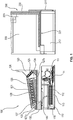
- the right picture of the FIG. 1 shows an aggregate support of a refrigerator and / or freezer according to the invention, which is generally designated by the reference numeral 100.
- the left picture of the FIG. 1 shows a device body of a refrigerator and / or freezer according to the invention, which is generally designated by the reference numeral 200.
- the FIG. 2 shows a sectional view through the lower portion of a refrigerator and / or freezer according to the invention, in which the unit carrier 100 is inserted into the device body 200. In the FIG. 2 are some in the FIG. 1 recognizable details not shown for reasons of clarity.
- the device body 200 comprises a frame substructure, which forms a base space 210 with the device bottom in the lowest area and in which a box-shaped vacuum insulation body is accommodated in the area above it, which defines an interior space 220.
- the vacuum insulation body serves as Heat insulation for the interior 220 and includes a barrier film and a support material disposed in the core enclosed by the barrier film. It is laminated all around to protect the barrier film.
- a plastic inner container is used in the interior opening of the vacuum insulation body.
- On the outside of the frame substructure is laminated with a ceiling plate, a rear panel and two side panels. The portion of the vacuum insulation body and the inner container forming the inner floor 221 are slightly set back from the opening plane of the inner space.
- the unit carrier 100 comprises a machine section 110 and an associated evaporator section 120.
- the machine section 110 forms the lower part of the unit carrier 100 and is dimensioned so that it can be pushed from the front into the base space 210 of the device body 200 and occupies this completely.
- the evaporator section 120 is mounted on the machine section 110 and dimensioned so that it can be inserted from the front in the lowest area of the heat-insulated interior 220 of the device body 200 and occupies this completely, so that the bottom 221 and the lowermost portions of the side walls and the rear wall 222 of the interior 220 are completely covered by the evaporator section 120.
- the machine section 110 and the evaporator section 120 are connected only by means of a connecting web 130, which is located in the front region of the unit carrier 100.
- a recess 140 is provided in the unit carrier 100 between the machine section 110 and the evaporator section 120, in which the vacuum-insulated bottom 221 of the device body 200 can be accommodated when the unit carrier 100 is inserted from the front into the device body 200 such that the machine section 110 into the base space 210 and the evaporator section 120 are pushed into the interior 220 of the device body 200.
- a compressor 111 and a condenser 112 are arranged, with the compressor 111 in the rear area and the condenser 112 in the front area of the machine section 110. Furthermore, in the front Area of the machine section 110 in thermal contact with the condenser 112 a thawed water tray 113 is arranged.
- the compressor 111 is installed with a sprung suspension 114 at the rear of the machine section 110.
- an opening 115 for cooling air which is blinded with air guide elements and a plurality of webs in the machine section 110 form a cooling air channel through which the cooling air returns from the opening 115 via the condenser 112 to the associated condensate tank 113 and the compressor 111 can flow to the opening 115.
- the rear side 211 of the base space 210 is closed by the wall section 211.
- a cooling air fan and a control unit which are not shown separately in the figure for reasons of clarity.
- electrical wiring with power supply which can be connected by the limitation of the base space 210 of the device body 200 to a power supply, is not shown in detail in the figure.
- a cold air passage 121 is formed which extends from an intake port 122 to an exhaust port 123.
- the suction opening 122 is located at the front end of the evaporator section 120 and in the installed state of the unit carrier 100 adjoins the inside of a device door 300 hinged to the device body 200.
- the outlet opening 123 is located at the rear end of the evaporator section 120 and adjoins the aggregate carrier 100 in the installed state the rear wall 222 of the device body 200.
- In the area near the outlet opening 123 of the cold air channel 121 is expanded and forms a fan chamber 124, in which an evaporator fan 125 is arranged.
- the rear end piece of the upper veneer 126 of the fan chamber 124 points vertically upwards and does not extend all the way to the rear end of the evaporator section, so that in the assembled state of the unit carrier 100 between the rear end piece of the upper veneer 126 of the fan chamber 124 and the rear wall 222 of the device body 200th a vertical channel portion is formed, which opens into a vertical air duct 223 in the uppermost region of the rear wall of the 222.
- a portion of the cold air passage 121 of the evaporator section 120 is expanded to a bell-shaped evaporator space 127, in which an evaporator 128 is arranged.
- the evaporator chamber 127 is slightly inclined in the evaporator section 120 and wins in the flow direction of the air in height.
- the evaporator 128 follows this course of the evaporator chamber 127 and is correspondingly installed slightly obliquely in the evaporator section 120.
- the cold air channel 121 is shaped so that both the air inlet opening 127a and the air outlet opening 127b of the evaporator chamber 127 are below the level of the evaporator.
- the cold air channel 121 is thus shaped so that during operation of the refrigerator and / or freezer, the air from the suction port 122 to the air inlet opening 127a drops below the level of the evaporator 128, then slowly rises in the evaporator chamber 127 and thereby passes the evaporator 128, and then again drops below the level of the evaporator 128 before entering the fan room 125.
- a likewise built in the evaporator section 120 condensate line is connected to the control unit and the power supply in the machine section 110 by means of a likewise not shown wiring.
- the evaporator 128 is connected by means of refrigerant pipes not shown in detail with the remaining, arranged in the machine section 110 components of the refrigerant circuit in combination.
- the corresponding cabling and refrigerant lines pass through the connecting web 130.
Landscapes
- Engineering & Computer Science (AREA)
- Chemical & Material Sciences (AREA)
- Combustion & Propulsion (AREA)
- Physics & Mathematics (AREA)
- Mechanical Engineering (AREA)
- Thermal Sciences (AREA)
- General Engineering & Computer Science (AREA)
- Devices That Are Associated With Refrigeration Equipment (AREA)
- Cold Air Circulating Systems And Constructional Details In Refrigerators (AREA)
Abstract
Description
- Die Erfindung betrifft ein Kühl- und/oder Gefriergerät mit einem Gerätekorpus, der wärmeisolierende Wandungen aufweist, die einen Innenraum umschließen, sowie mit einem Kältemittelkreislauf, der als Komponenten einen Kompressor, einen Verflüssiger, eine Drossel und einen Verdampfer umfasst. Die Erfindung betrifft ferner ein Verfahren zur Herstellung eines derartigen Kühl- und/oder Gefriergeräts.
- Es ist bekannt, einzelne Komponenten eines Kühl- und/oder Gefriergerätes auf einem gemeinsamen Träger anzuordnen, um den Zusammenbau und die Wartung von Geräten zu vereinfachen. Ferner ist bekannt, Komponenten des Kältemittelkreislaufs unten im Gerät einzubauen, da sich zum einen eine bessere Ergonomie für den Kunden als auch eine bessere Standfestigkeit des Gerätes ergibt. Gleichwohl sollte aus Gründen der natürlichen Konvektion im Innenraum des Gerätes, wonach kalte Luft absinkt und warme Luft aufsteigt, der Verdampfer eher im oberen Bereich des Innenraums angeordnet werden. Wollte man den Verdampfer und die verbleibenden Komponenten des Kältemittelkreislaufs unten anordnen, wäre man mit Problemen konfrontiert, die sich aus der gegenläufigen natürlichen Konvektion ergeben. Beispielsweise müsste warme und feuchte Luft daran gehindert werden, nach oben zu strömen und an nicht abtaubeheizten kalten Flächen zu kondensieren. Klappen und dergleichen sollten aber möglichst vermieden werden, da diese teuer und wartungsintensiv sind.
- Aufgabe der Erfindung ist es, ein verbessertes Kühl- und/oder Gefriergerät bereitzustellen, das die oben genannten Probleme aus dem Stand der Technik überwindet.
- Vor diesem Hintergrund betrifft die Erfindung ein Kühl- und/oder Gefriergerät mit einem Gerätekorpus, der wärmeisolierende Wandungen aufweist, die einen Innenraum umschließen, sowie mit einem Kältemittelkreislauf, der als Komponenten einen Kompressor, einen Verflüssiger, eine Drossel und einen Verdampfer umfasst, wobei das Gerät einen Kaltluftkanal aufweist, der in einem Abschnitt zu einem Verdampferraum erweitert ist, dass der Verdampfer in diesem Verdampferraum angeordnet ist, und dass die Lufteintrittsöffnung als auch die Luftaustrittsöffnung des Verdampferraums unter dem Niveau des Verdampfers liegen.
- Der Verdampfer ist vorzugsweise vollständig in dem Verdampferraum angeordnet. Durch die Anordnung sowohl der Lufteintrittsöffnung als auch der Luftaustrittsöffnung des Verdampferraums unter dem Niveau des Verdampfers werden Zuluft und Abluft nur von unten angebunden und über dem Verdampfer eine Glocke ausgebildet. Etwaige nicht ausreichend gekühlte und warme Luft bleibt in der Glocke eingesperrt und kann den Verdampfer abtauen. Hierdurch kann eine im Aggregatträger und gegebenenfalls im Verdampferabschnitt des Aggregatträgers verbaute Abtauheizung unterstützt werden. Möglich ist auch, komplett auf eine Abtauheizung zu verzichten. Jedenfalls wird die Abtauenergie besonders effizient eingesetzt.
- In einer Ausführungsform ist vorgesehen, dass der Gerätekorpus eine Vollvakuumdämmung aufweist, wobei der Innenraum von einem einteiligen, kistenförmigen Vakuumisolationskörper umgeben ist. Die wärmeisolierenden Wandungen des Gerätekorpus sind in dieser Ausführungsform Abschnitte des Wakuumisolationskörpers. Es kann vorgesehen sein, dass der Vakuumisolationskörper eine Barrierefolie und ein im von der Barrierefolie eingeschlossenen Kern angeordnetes Stützmaterial umfasst.
- Ferner kann der Gerätekorpus eine Rahmenunterkonstruktion aufweisen, welche sich über die gesamte Höhe des Gerätes erstreckt und den Bereich des Innenraums ebenso umgibt wie einen Sockelbereich ausbildet. Der kistenförmige Vakuumisolationskörper kann in diese Rahmenkonstruktion eingesetzt werden. Die Rahmenunterkonstruktion kann ferner zur Aufnahme des Aggregatträgers dienen. Sie kann auch den Boden des Gerätekorpus ausbilden. Sie verleiht dem Gerätekorpus Stabilität.
- Um den Vakuumisolationskörper zu schützen, kann vorgesehen sein, diesen vollständig zu kaschieren. Zum einen kann dabei vorgesehen sein, dass in den kistenförmigen Vakuumisolationskörper ein Kunststoffinnenbehälter eingesetzt ist. Ferner kann vorgesehen sein, dass die Außenseite der Rahmenunterkonstruktion mit Wandplatten und vorzugsweise Wandblechen verschalt ist. Die Verbindung zwischen den Wandplatten, dem Innenbehälter, dem Vakuumisolationskörper und der Rahmenunterkonstruktion kann durch Verkleben, Verschrauben, Verrasten und vorzugsweise eine Kombination daraus erfolgen.
- In einer Ausführungsform ist vorgesehen, dass alle Komponenten des Kältemittelkreislaufs gemeinsam auf einem Aggregatträger verbaut sind, das insgesamt vom Gerätekorpus getrennt und aus dem Gerät entnommen werden kann, wobei der Kaltluftkanal ebenfalls im Aggregatträger ausgebildet ist.
- Es ist somit vorgesehen, dass ein Aggregatträger mit allen Komponenten des Kältemittelkreislaufs insgesamt vom Gerätekorpus getrennt werden kann. Dies schließt auch die Rohrleitungen und etwaige weitere Komponenten des Kältemittelkreislaufs wie Trockner oder Sammler mit ein. Dies ist insbesondere deshalb bemerkenswert, da sowohl Komponenten der warmen Seite des Kältemittelkreislaufs, also Kompressor und Verflüssiger, als auch Komponenten der kalten Seite des Kältemittelkreislaufs, also der Verdampfer, gemeinsam auf einem Aggregatträger verbaut sind, das insgesamt vom Gerätekorpus getrennt und aus dem Kühlgerät entnommen werden kann. Entsprechend können bei der Zusammensetzung des Gerätes diese Komponenten auch in einem einzigen Arbeitsschritt durch Einsetzen des Aggregatträgers im Gerät verbaut werden. Eine Vereinfachung ergibt sich auch bei der Durchführung allfälliger Reparaturarbeiten. Diese Vereinfachungen gehen über die mit den aus dem Stand der Technik bekannten Maßnahmen erreichbaren Vereinfachungen hinaus.
- Der lösbar mit dem Gerätekorpus in Verbindung stehende Aggregatträger kann beispielweise anhand von Schraubverbindungen befestigt sein. Beispielsweise kann auch vorgesehen sein, dass der Aggregatträger werkzeugfrei vom Gerätekorpus gelöst werden kann und beispielsweise lediglich anhand von Rastverbindungen mit diesem in Verbindung steht.
- In einer Ausführungsform ist vorgesehen, dass der Verdampfer und der Verdampferkanal und vorzugsweise der Aggregatträger mit Verdampfer und Verdampferkanal im unteren Bereich des Gerätekorpus verbaut sind. Durch den Einbau schwerer Komponenten des Kältemittelkreislaufs in den unteren Bereich bzw. Sockelbereich des Geräts ergibt sich eine hohe Standsicherheit. Ferner ergibt sich durch einen tiefen Einbau eine bessere Ergonomie für den Kunden, da weiter obenliegende Fächer besser zugänglich sind und der schlechter zugängliche Bereich im Sockelbereich des Gerätes durch den Aggregatträger eingenommen wird. Letztlich kann allfälliges Tauwasser einfach nach unten abfließen.
- In einer Ausführungsform ist vorgesehen, dass ferner eine oder mehrere Komponenten ausgewählt aus der Gruppe eines Maschinenraumventilators, eines Kühlraumventilators, einer Steuereinheit, einer Tauwasserschale und eines Netzteils mit Verkabelung auf dem Aggregatträger verbaut sind. Dies führt zu einer weiteren Vereinfachung bei der Zusammensetzung des Geräts und zu einer Vereinfachung bei der Durchführung allfälliger Reparaturarbeiten.
- In einer Ausführungsform ist vorgesehen, dass der Aggregatträger ein Maschinenabschnitt und einen damit verbundenen Verdampferabschnitt umfasst, wobei der Kompressor sowie der Verflüssiger im Maschinenabschnitt und der Verdampfer sowie der Kaltluftkanal im Verdampferabschnitt aufgenommen sind. In dieser Ausführungsform ist also vorgesehen, die Komponenten der warmen Seite des Kältemittelkreislaufs und die Komponenten der kalten Seite des Kältemittelkreislaufs auf unterschiedliche Abschnitte innerhalb des einen integralen Aggregatträgers zu verteilen. Im Falle einer derartigen Aufteilung kann vorgesehen sein, dass Komponenten wie ein Maschinenraumventilator, eine Steuereinheit, eine Tauwasserschale oder ein Netzteil mit Verkabelung im Maschinenabschnitt und Komponenten wie ein Kühlraumventilator im Verdampferabschnitt aufgenommen sind.
- Denkbar ist es weiterhin, dass in einem neben der Verbindung liegenden Freiraum zwischen dem Maschinenabschnitt und dem Verdampferabschnitt eine zum Gerätekorpus gehörige Wärmeisolationsschicht angeordnet ist. Bei der Wärmeisolationsschicht kann es sich um einen Teilabschnitt der Vollvakuumdämmung handeln. Die Verbindung kann beispielsweise durch einen im vorderen Bereich des Geräts verlaufenden Steg gebildet werden, der zum Maschinenabschnitt oder dem Verdampferabschnitt gehört oder durch ein separates Zwischenstück gebildet wird.
- In diesem Fall kann der Boden des gekühlten Innenraums beziehungsweise können der den Innenraumboden ausbildende Abschnitt des Vakuumisolationskörpers und des Innenbehälters gegenüber der Öffnungsebene des Innenraums etwas zurückversetzt sein. Die Wärmeisolationsschicht ist Teil des Gerätekorpus und füllt eine Freilassung des Aggregatträgers zwischen Maschinenabschnitt und Verdampferbschnitt und neben dem Verbindungselement aus. Die Verbindung selbst kann ebenfalls Dämmmaterial umfassen, um auch in diesem Bereich die Ausbildung eine Wärmebrücke zu vermeiden.
- In einer Ausführungsform ist vorgesehen, dass der Maschinenabschnitt des Aggregatträgers in einem Sockelraum des Gerätekorpus und der Verdampferabschnitt des Aggregatträgers im untersten Bereich des Innenraums aufgenommen sind. In diesem Fall liegt der Maschinenabschnitt unterhalb des Verdampferabschnittes. Vorzugsweise ist der Maschinenabschnitt so dimensioniert, dass es den Sockelraum des Gerätekorpus vollständig ausfüllt und der Verdampferabschnitt so dimensioniert, dass es den untersten Bereich des wärmeisolierten Innenraums derart vollständig einnimmt, dass der Boden und die untersten Abschnitte der Rückwand und gegebenenfalls auch der Seitenwände des Innenraums vollständig vom Verdampferabschnitt überdeckt werden. Vorzugsweise ist der Sockelraum wie auch der Innenraum nach vorne hin geöffnet, sodass der Aggregatträger im Falle einer Demontage nach vorne aus dem Gerätekorpus gezogen werden kann und, im Umkehrschluss, bei der Montage von vorne in den Gerätekorpus eingeschoben werden kann.
- Bevorzugt ist es, wenn der Verdampferraum gegenüber der Horizontalen geneigt verläuft und in Strömungsrichtung der Luft an Höhe gewinnt. Der Verdampfer kann diesem Verlauf des Verdampferraums folgen und entsprechend gegenüber der Horizontalen geneigt im Aggregatträger verbaut sein. Hierdurch kann der beschriebene Effekt der effizienten Nutzung der Abtauenergie noch verstärkt werden.
- In einer weiteren Ausführungsform ist vorgesehen, dass im Kaltluftkanal keine elektrisch betriebenen Klappen und vorzugsweise überhaupt keine Klappen verbaut sind. Ein Verzicht auf Klappen führt zu einer Kostenersparnis und einer verringerten Störungsanfälligkeit. Die Möglichkeit eines Verzichts auf Klappen ohne Funktionsverlust ergibt sich insbesondere bei der zuvor beschriebenen glockenartigen Ausbildung des Verdampferraums.
- Die Erfindung betrifft weiterhin ein Verfahren zur Herstellung eines erfindungsgemäßen Kühl- und/oder Gefriergeräts mit einem Aggregatträger, auf dem alle Komponenten des Kältemittelkreislaufs gemeinsam verbaut sind, wobei der Aggregatträger als Ganzes in den Gerätekorpus eingesetzt wird. Vorzugsweise wird der Aggregatträger von vorne den Gerätekorpus eingeschoben. Vorzugsweise wird der Aggregatträger in einen unteren Bereich des Gerätekorpus eingesetzt.
- An dieser Stelle wird darauf hingewiesen, dass die Begriffe "ein" und "eine" nicht zwingend auf genau eines der Elemente verweisen, wenngleich dies eine mögliche Ausführung darstellt, sondern auch eine Mehrzahl der Elemente bezeichnen können. Ebenso schließt die Verwendung des Plurals auch das Vorhandensein des fraglichen Elementes in der Einzahl ein und umgekehrt umfasst der Singular auch mehrere der fraglichen Elemente.
- Weitere Einzelheiten und Vorteile der Erfindung ergeben sich aus dem nachfolgend anhand der Figuren dargestellten Ausführungsbeispiel. In den Figuren zeigen:
- Figur 1:
- seitliche Schnittansichten des unteren Bereichs eines Gerätekorpus eines erfindungsgemäßen Kühl- und/oder Gefriergerätes sowie eines zum Einsetzen in diesen Bereich bestimmten Aggregatträgers; und
- Figur 2:
- eine seitliche Teilschnittansicht durch den unteren Bereich des durch Einsetzen des Aggregatträgers erhaltenen erfindungsgemäßen Kühl- und/oder Gefriergerätes.
- Die rechte Abbildung der
Figur 1 zeigt einen Aggregatträger eines erfindungsgemäßen Kühl- und/oder Gefriergeräts, der allgemein mit dem Bezugszeichen 100 gekennzeichnet ist. Die linke Abbildung derFigur 1 zeigt einen Gerätekorpus eines erfindungsgemäßen Kühl- und/oder Gefriergeräts, der allgemein mit dem Bezugszeichen 200 gekennzeichnet ist. DieFigur 2 zeigt eine Schnittansicht durch den unteren Bereich eines erfindungsgemäßen Kühl- und/oder Gefriergeräts, in dem der Aggregatträger 100 in den Gerätekorpus 200 eingesetzt ist. In derFigur 2 sind einige in derFigur 1 erkennbare Details aus Gründen der Übersichtlichkeit nicht wiedergegeben. - Der Gerätekorpus 200 umfasst eine Rahmenunterkonstruktion, welche im untersten Bereich einen Sockelraum 210 mit dem Geräteboden ausbildet und in welcher im darüberliegenden Bereich ein kistenförmiger Vakuumisolationskörper aufgenommen ist, der einen Innenraum 220 definiert. Der Vakuumisolationskörper dient als Wärmeisolation für den Innenraum 220 und umfasst eine Barrierefolie und ein im von der Barrierefolie eingeschlossenen Kern angeordnetes Stützmaterial. Er ist rundum kaschiert, um die Barrierefolie zu schützen. In die Innenraumöffnung des Vakuumisolationskörpers ist ein Kunststoffinnenbehälter eingesetzt. An der Außenseite ist die Rahmenunterkonstruktion mit einem Deckenblech, einem Rückwandblech und mit zwei Seitenwandblechen kaschiert. Der den Innenraumboden 221 ausbildende Abschnitt des Vakuumisolationskörpers und des Innenbehälters sind gegenüber der Öffnungsebene des Innenraums etwas zurückversetzt.
- Der Aggregatträger 100 umfasst einen Maschinenabschnitt 110 und einen damit verbundenen Verdampferabschnitt 120. Der Maschinenabschnitt 110 bildet den unteren Teil des Aggregatträgers 100 aus und ist so dimensioniert, dass es von vorne in den Sockelraum 210 des Gerätekorpus 200 eingeschoben werden kann und diesen vollständig einnimmt. Der Verdampferabschnitt 120 ist auf den Maschinenabschnitt 110 aufgesetzt und so dimensioniert, dass es von vorne in den untersten Bereich des wärmeisolierten Innenraums 220 des Gerätekorpus 200 eingeschoben werden kann und diesen vollständig einnimmt, sodass der Boden 221 und die untersten Abschnitte der Seitenwände und der Rückwand 222 des Innenraums 220 vollständig vom Verdampferabschnitt 120 überdeckt sind. Der Maschinenabschnitt 110 und der Verdampferabschnitt 120 sind nur anhand eines Verbindungsstegs 130 verbunden, der sich im vorderen Bereich des Aggregatträgers 100 befindet. Hinter dem Verbindungssteg 130 ist im Aggregatträger 100 zwischen Maschinenabschnitt 110 und Verdampferabschnitt 120 eine Aussparung 140 vorgesehen, in welcher der vakuumisolierte Boden 221 des Gerätekorpus 200 Platz finden kann, wenn der Aggregatträger 100 derart von vorne in den Gerätekorpus 200 eingeschoben wird, dass der Maschinenabschnitt 110 in den Sockelraum 210 und der Verdampferabschnitt 120 in den Innenraum 220 des Gerätekorpus 200 geschoben werden.
- Im Maschinenabschnitt 110 sind ein Kompressor 111 und ein Verflüssiger 112 angeordnet, wobei sich der Kompressor 111 im hinteren Bereich und der Verflüssiger 112 im vorderen Bereich des Maschinenabschnitts 110 befinden. Ferner ist im vorderen Bereich des Maschinenabschnitts 110 in thermischem Kontakt mit dem Verflüssiger 112 eine Tauwasserschale 113 angeordnet. Der Kompressor 111 ist mit einer gefederten Aufhängung 114 im hinteren Bereich des Maschinenabschnitts 110 verbaut. An der Vorderseite des Maschinenabschnitts 110 befindet sich eine mit Luftleitelementen verblendete Öffnung 115 für Kühlluft und mehrere Stege im Maschinenabschnitt 110 bilden einen Kühlluftkanal aus, durch den Kühlluft ausgehend von der Öffnung 115 über den Verflüssiger 112 mit der zugeordneten Tauwasserschale 113 und den Kompressor 111 wieder zurück zur Öffnung 115 strömen kann. Die Rückseite 211 des Sockelraums 210 ist durch den Wandabschnitt 211 verschlossen. Ebenfalls im Maschinenabschnitt 110 angeordnet sind ein Kühlluftventilator und eine Steuereinheit, die aber in der Figur aus Gründen der Übersichtlichkeit nicht gesondert dargestellt sind. Auch eine im Maschinenabschnitt 110 angeordnete elektrische Verkabelung mit Netzteil, die durch die Begrenzung des Sockelraums 210 des Gerätekorpus 200 an eine Stromversorgung angeschlossen werden kann, ist in der Figur nicht näher dargestellt.
- Im Verdampferabschnitt 120 ist ein Kaltluftkanal 121 ausgebildet, der sich von einer Ansaugöffnung 122 bis zu einer Auslassöffnung 123 erstreckt. Die Ansaugöffnung 122 befindet sich am vorderen Ende des Verdampferabschnitts 120 und grenzt im eingebauten Zustand des Aggregatträgers 100 an die Innenseite einer am Gerätekorpus 200 angelenkten Gerätetüre 300. Die Auslassöffnung 123 befindet sich am hinteren Ende des Verdampferabschnitts 120 und grenzt im eingebauten Zustand des Aggregatträgers 100 an die Rückwand 222 des Gerätekorpus 200. Im Bereich nahe der Auslassöffnung 123 ist der Kaltluftkanal 121 erweitert und bildet einen Ventilatorraum 124 aus, in dem ein Verdampferventilator 125 angeordnet ist. Das hintere Endstück der oberen Verblendung 126 des Ventilatorraums 124 zeigt senkrecht nach oben und reicht nicht ganz bis zum hinteren Ende des Verdampferabschnitts, sodass im eingebauten Zustand des Aggregatträgers 100 zwischen dem hinteren Endstück der oberen Verblendung 126 des Ventilatorraums 124 und der Rückwand 222 des Gerätekorpus 200 ein senkrechter Kanalabschnitt ausgebildet wird, der in einen vertikalen Luftführungskanal 223 im weiter oben liegenden Bereich der Rückwand des 222 mündet.
- Zwischen der Ansaugöffnung 122 und dem Ventilatorraum 124 ist ein Abschnitt des Kaltluftkanals 121 des Verdampferabschnitts 120 zu einem glockenförmigen Verdampferraum 127 erweitert, in dem ein Verdampfer 128 angeordnet ist. Der Verdampferraum 127 liegt leicht schräg im Verdampferabschnitt 120 und gewinnt in Strömungsrichtung der Luft an Höhe. Der Verdampfer 128 folgt diesem Verlauf des Verdampferraums 127 und ist entsprechend leicht schräg im Verdampferabschnitt 120 verbaut. Der Kaltluftkanal 121 ist so geformt, dass sowohl die Lufteintrittsöffnung 127a als auch die Luftaustrittsöffnung 127b des Verdampferraums 127 unter dem Niveau des Verdampfers liegen. Der Kaltluftkanal 121 ist also so geformt, dass im Betrieb des Kühl- und/oder Gefriergerätes die Luft ausgehend von der Ansaugöffnung 122 zur Lufteintrittsöffnung 127a bis unter das Niveau des Verdampfers 128 absinkt, dann im Verdampferraum 127 langsam steigt und dabei den Verdampfer 128 passiert, und dann wieder unter das Niveau des Verdampfers 128 absinkt, bevor sie in den Ventilatorraum 125 gelangt.
- Nicht näher dargestellt ist in der Figur aus Gründen der Übersichtlichkeit eine ebenfalls im Verdampferabschnitt 120 verbaute Tauwasserleitung. Der Verdampferventilator 125 steht anhand einer ebenfalls nicht dargestellten Verkabelung mit der Steuereinheit und dem Netzteil im Maschinenabschnitt 110 in Verbindung. Der Verdampfer 128 steht anhand nicht im Detail dargestellter Kältemittelleitungen mit den verbleibenden, im Maschinenabschnitt 110 angeordneten Bauteilen des Kältemittelkreislaufs in Verbindung. Die entsprechenden Verkabelungen und Kältemittelleitungen verlaufen durch den Verbindungssteg 130.
Claims (10)
- Kühl- und/oder Gefriergerät mit einem Gerätekorpus, der wärmeisolierende Wandungen aufweist, die einen Innenraum umschließen, sowie mit einem Kältemittelkreislauf, der als Komponenten einen Kompressor, einen Verflüssiger, eine Drossel und einen Verdampfer umfasst,
dadurch gekennzeichnet,
dass das Gerät einen Kaltluftkanal aufweist, der in einem Abschnitt zu einem Verdampferraum erweitert ist, wobei der Verdampfer in diesem Verdampferraum angeordnet ist und wobei die Lufteintrittsöffnung als auch die Luftaustrittsöffnung des Verdampferraums unter dem Niveau des Verdampfers liegen. - Kühl- und/oder Gefriergerät nach Anspruch 1, dadurch gekennzeichnet, dass der Gerätekorpus eine Vollvakuumdämmung aufweist, wobei der Innenraum von einem durchgehenden, kistenförmigen Vakuumisolationskörper umgeben ist.
- Kühl- und/oder Gefriergerät nach einem der vorhergehenden Ansprüche, dadurch gekennzeichnet, dass alle Komponenten des Kältemittelkreislaufs gemeinsam auf einem Aggregatträger verbaut sind, das insgesamt vom Gerätekorpus getrennt und aus dem Gerät entnommen werden kann, wobei der Kaltluftkanal ebenfalls im Aggregatträger ausgebildet ist.
- Kühl- und/oder Gefriergerät nach einem der vorhergehenden Ansprüche, dadurch gekennzeichnet, dass der Verdampfer und der Verdampferkanal und vorzugsweise der Aggregatträger mit Verdampfer und Verdampferkanal im unteren Bereich des Gerätekorpus verbaut sind.
- Kühl- und/oder Gefriergerät nach einem der Ansprüche 3 bis 4, dadurch gekennzeichnet, dass ferner eine oder mehrere Komponenten ausgewählt aus der Gruppe eines Maschinenraumventilators, eines Kühlraumventilators, einer Steuereinheit, einer Tauwasserschale und eines Netzteils mit Verkabelung auf dem Aggregatträger verbaut sind.
- Kühl- und/oder Gefriergerät nach einem der Ansprüche 3 bis 5, dadurch gekennzeichnet, dass der Aggregatträger einen Maschinenabschnitt und einen damit verbundenen Verdampferabschnitt umfasst, wobei der Kompressor sowie der Verflüssiger im Maschinenabschnitt und der Verdampfer sowie der Kaltluftkanal im Verdampferabschnitt aufgenommen sind.
- Kühl- und/oder Gefriergerät nach Anspruch 6, dadurch gekennzeichnet, dass in einem neben der Verbindung liegenden Freiraum zwischen dem Maschinenabschnitt und dem Verdampferabschnitt eine zum Gerätekorpus gehörige Wärmeisolationsschicht angeordnet ist.
- Kühl- und/oder Gefriergerät nach Anspruch 6 oder 7, dadurch gekennzeichnet, dass der Maschinenabschnitt in einem Sockelraum des Gerätekorpus und der Verdampferabschnitt im untersten Bereich des Innenraums aufgenommen ist.
- Kühl- und/oder Gefriergerät nach einem der vorhergehenden Ansprüche, dadurch gekennzeichnet, dass der Verdampferraum gegenüber der Horizontalen geneigt verläuft und in Strömungsrichtung der Luft an Höhe gewinnt.
- Kühl- und/oder Gefriergerät nach einem der vorhergehenden Ansprüche, dadurch gekennzeichnet, dass im Kaltluftkanal keine elektrisch betriebenen Klappen und vorzugsweise überhaupt keine Klappen verbaut sind.
Applications Claiming Priority (1)
| Application Number | Priority Date | Filing Date | Title |
|---|---|---|---|
| DE102017119022.8A DE102017119022A1 (de) | 2017-08-21 | 2017-08-21 | Kühl- und/oder Gefriergerät |
Publications (2)
| Publication Number | Publication Date |
|---|---|
| EP3447414A1 true EP3447414A1 (de) | 2019-02-27 |
| EP3447414B1 EP3447414B1 (de) | 2025-05-21 |
Family
ID=63350429
Family Applications (1)
| Application Number | Title | Priority Date | Filing Date |
|---|---|---|---|
| EP18189982.4A Active EP3447414B1 (de) | 2017-08-21 | 2018-08-21 | Kühl- und/oder gefriergerät |
Country Status (3)
| Country | Link |
|---|---|
| EP (1) | EP3447414B1 (de) |
| DE (1) | DE102017119022A1 (de) |
| ES (1) | ES3039282T3 (de) |
Cited By (2)
| Publication number | Priority date | Publication date | Assignee | Title |
|---|---|---|---|---|
| EP4345404A1 (de) * | 2022-09-27 | 2024-04-03 | Liebherr-Hausgeräte Lienz GmbH | Kühl- und/oder gefriergerät |
| EP4174414B1 (de) * | 2020-08-18 | 2025-04-02 | Qingdao Haier Refrigerator Co., Ltd. | Eingebetteter kühlschrank |
Citations (4)
| Publication number | Priority date | Publication date | Assignee | Title |
|---|---|---|---|---|
| US2962870A (en) * | 1958-01-20 | 1960-12-06 | Revco Inc | Defrosting system and apparatus |
| DE1401509A1 (de) * | 1960-07-15 | 1969-05-29 | Pet Inc | Kuehlanlage |
| US3712078A (en) * | 1971-11-22 | 1973-01-23 | Krispin Eng Ltd | Refrigeration unit |
| GB2227302A (en) * | 1989-01-09 | 1990-07-25 | Fawn Eng Corp | Vending machine refrigeration system |
Family Cites Families (7)
| Publication number | Priority date | Publication date | Assignee | Title |
|---|---|---|---|---|
| US6701739B2 (en) * | 2002-06-12 | 2004-03-09 | Tecumseh Products Company | Modular refrigeration system for refrigeration appliance |
| FR2855871B1 (fr) * | 2003-06-06 | 2005-11-18 | Tecumseh Europe Sa | Dispositif de regrigeration |
| JP4493478B2 (ja) * | 2004-11-25 | 2010-06-30 | 三洋電機株式会社 | 冷却貯蔵庫 |
| US9285157B2 (en) * | 2008-05-23 | 2016-03-15 | Aktiebolaget Electrolux | Cold appliance |
| DE102009041304A1 (de) * | 2009-09-15 | 2011-03-17 | Bpv Gmbh | Vorrichtung für die Lagerung von temperatur- und/oder feuchtigkeitsabhängigen Wirkstoffen |
| DE102012020106A1 (de) * | 2011-10-19 | 2013-04-25 | Thermo Fisher Scientific (Asheville) LLC (n. d. Ges. d. Staates Delaware) | HOCHLEISTUNGSKÜHLGERÄT MIT VERDAMPFER AUßERHALB DES SCHRANKS |
| DK177870B1 (en) * | 2013-10-10 | 2014-10-20 | Gram Commercial As | A cooling unit for a climatized cabinet |
-
2017
- 2017-08-21 DE DE102017119022.8A patent/DE102017119022A1/de active Pending
-
2018
- 2018-08-21 EP EP18189982.4A patent/EP3447414B1/de active Active
- 2018-08-21 ES ES18189982T patent/ES3039282T3/es active Active
Patent Citations (4)
| Publication number | Priority date | Publication date | Assignee | Title |
|---|---|---|---|---|
| US2962870A (en) * | 1958-01-20 | 1960-12-06 | Revco Inc | Defrosting system and apparatus |
| DE1401509A1 (de) * | 1960-07-15 | 1969-05-29 | Pet Inc | Kuehlanlage |
| US3712078A (en) * | 1971-11-22 | 1973-01-23 | Krispin Eng Ltd | Refrigeration unit |
| GB2227302A (en) * | 1989-01-09 | 1990-07-25 | Fawn Eng Corp | Vending machine refrigeration system |
Cited By (2)
| Publication number | Priority date | Publication date | Assignee | Title |
|---|---|---|---|---|
| EP4174414B1 (de) * | 2020-08-18 | 2025-04-02 | Qingdao Haier Refrigerator Co., Ltd. | Eingebetteter kühlschrank |
| EP4345404A1 (de) * | 2022-09-27 | 2024-04-03 | Liebherr-Hausgeräte Lienz GmbH | Kühl- und/oder gefriergerät |
Also Published As
| Publication number | Publication date |
|---|---|
| DE102017119022A1 (de) | 2019-02-21 |
| ES3039282T3 (en) | 2025-10-20 |
| EP3447414B1 (de) | 2025-05-21 |
Similar Documents
| Publication | Publication Date | Title |
|---|---|---|
| DE1401509A1 (de) | Kuehlanlage | |
| CH402906A (de) | Kühltruhe | |
| WO2012136532A1 (de) | Kombinationskältegerät | |
| DE1501036A1 (de) | Wasserkuehlsystem fuer Kuehlanlagen | |
| EP3194869A1 (de) | Kältegerät mit mehreren lagerkammern | |
| DE2745963C2 (de) | Kühlvitrine | |
| DE202005014373U1 (de) | No-Frost-Kältegerät | |
| EP3447414B1 (de) | Kühl- und/oder gefriergerät | |
| DE2804008A1 (de) | Verfahren und einrichtung zum abtauen der kuehlelemente in einer gewerblichen kuehl- oder gefriertruhe | |
| EP3447412B1 (de) | Kühl- und/oder gefriergerät verfahren zur herstellung desselben | |
| EP2697578A1 (de) | Kältegerät mit verdunstungsschale | |
| WO2006058819A1 (de) | Einbaukältegerät | |
| EP0547311B1 (de) | Haushaltskühlgerät | |
| EP2378227A1 (de) | Kühlschrank | |
| DE102017005226A1 (de) | Sockelkonzept | |
| DE202024002670U1 (de) | Kühlschrank | |
| DE102004058197A1 (de) | Kältegerät | |
| DE102007017011A1 (de) | Kühl- und/oder Gefriergerät | |
| EP0073363B1 (de) | Verdampfer für ein Mehr-Temperaturen Kühlgerät | |
| EP1845322B1 (de) | Kühl- und/oder Gefriergerät | |
| DE102023212101B4 (de) | Kältegerät und Verfahren zum Montieren eines Kältegeräts | |
| DE102016224389A1 (de) | No-Frost-Haushaltskältegerät mit zur Rückwand dichtender Trennplatte | |
| CH711097B1 (de) | Kühlgerät sowie Tauwasserleitung für ein derartiges Kühlgerät. | |
| DE102012014342A1 (de) | System von mehreren Kühl- und/oder Gefriergeräten | |
| DE102009000840A1 (de) | Kältegerät mit vergleichmäßiger Temperaturverteilung |
Legal Events
| Date | Code | Title | Description |
|---|---|---|---|
| PUAI | Public reference made under article 153(3) epc to a published international application that has entered the european phase |
Free format text: ORIGINAL CODE: 0009012 |
|
| STAA | Information on the status of an ep patent application or granted ep patent |
Free format text: STATUS: THE APPLICATION HAS BEEN PUBLISHED |
|
| AK | Designated contracting states |
Kind code of ref document: A1 Designated state(s): AL AT BE BG CH CY CZ DE DK EE ES FI FR GB GR HR HU IE IS IT LI LT LU LV MC MK MT NL NO PL PT RO RS SE SI SK SM TR |
|
| AX | Request for extension of the european patent |
Extension state: BA ME |
|
| STAA | Information on the status of an ep patent application or granted ep patent |
Free format text: STATUS: REQUEST FOR EXAMINATION WAS MADE |
|
| 17P | Request for examination filed |
Effective date: 20190820 |
|
| STAA | Information on the status of an ep patent application or granted ep patent |
Free format text: STATUS: EXAMINATION IS IN PROGRESS |
|
| 17Q | First examination report despatched |
Effective date: 20201021 |
|
| GRAP | Despatch of communication of intention to grant a patent |
Free format text: ORIGINAL CODE: EPIDOSNIGR1 |
|
| STAA | Information on the status of an ep patent application or granted ep patent |
Free format text: STATUS: GRANT OF PATENT IS INTENDED |
|
| INTG | Intention to grant announced |
Effective date: 20250121 |
|
| GRAS | Grant fee paid |
Free format text: ORIGINAL CODE: EPIDOSNIGR3 |
|
| GRAA | (expected) grant |
Free format text: ORIGINAL CODE: 0009210 |
|
| STAA | Information on the status of an ep patent application or granted ep patent |
Free format text: STATUS: THE PATENT HAS BEEN GRANTED |
|
| AK | Designated contracting states |
Kind code of ref document: B1 Designated state(s): AL AT BE BG CH CY CZ DE DK EE ES FI FR GB GR HR HU IE IS IT LI LT LU LV MC MK MT NL NO PL PT RO RS SE SI SK SM TR |
|
| REG | Reference to a national code |
Ref country code: GB Ref legal event code: FG4D Free format text: NOT ENGLISH |
|
| REG | Reference to a national code |
Ref country code: CH Ref legal event code: EP |
|
| REG | Reference to a national code |
Ref country code: DE Ref legal event code: R096 Ref document number: 502018015825 Country of ref document: DE |
|
| REG | Reference to a national code |
Ref country code: IE Ref legal event code: FG4D Free format text: LANGUAGE OF EP DOCUMENT: GERMAN |
|
| REG | Reference to a national code |
Ref country code: NL Ref legal event code: MP Effective date: 20250521 |
|
| PG25 | Lapsed in a contracting state [announced via postgrant information from national office to epo] |
Ref country code: PT Free format text: LAPSE BECAUSE OF FAILURE TO SUBMIT A TRANSLATION OF THE DESCRIPTION OR TO PAY THE FEE WITHIN THE PRESCRIBED TIME-LIMIT Effective date: 20250922 Ref country code: FI Free format text: LAPSE BECAUSE OF FAILURE TO SUBMIT A TRANSLATION OF THE DESCRIPTION OR TO PAY THE FEE WITHIN THE PRESCRIBED TIME-LIMIT Effective date: 20250521 |
|
| PGFP | Annual fee paid to national office [announced via postgrant information from national office to epo] |
Ref country code: ES Payment date: 20250902 Year of fee payment: 8 |
|
| PGFP | Annual fee paid to national office [announced via postgrant information from national office to epo] |
Ref country code: DE Payment date: 20250828 Year of fee payment: 8 |
|
| REG | Reference to a national code |
Ref country code: LT Ref legal event code: MG9D |
|
| PG25 | Lapsed in a contracting state [announced via postgrant information from national office to epo] |
Ref country code: NO Free format text: LAPSE BECAUSE OF FAILURE TO SUBMIT A TRANSLATION OF THE DESCRIPTION OR TO PAY THE FEE WITHIN THE PRESCRIBED TIME-LIMIT Effective date: 20250821 Ref country code: GR Free format text: LAPSE BECAUSE OF FAILURE TO SUBMIT A TRANSLATION OF THE DESCRIPTION OR TO PAY THE FEE WITHIN THE PRESCRIBED TIME-LIMIT Effective date: 20250822 |
|
| PG25 | Lapsed in a contracting state [announced via postgrant information from national office to epo] |
Ref country code: PL Free format text: LAPSE BECAUSE OF FAILURE TO SUBMIT A TRANSLATION OF THE DESCRIPTION OR TO PAY THE FEE WITHIN THE PRESCRIBED TIME-LIMIT Effective date: 20250521 Ref country code: NL Free format text: LAPSE BECAUSE OF FAILURE TO SUBMIT A TRANSLATION OF THE DESCRIPTION OR TO PAY THE FEE WITHIN THE PRESCRIBED TIME-LIMIT Effective date: 20250521 |
|
| PGFP | Annual fee paid to national office [announced via postgrant information from national office to epo] |
Ref country code: IT Payment date: 20250827 Year of fee payment: 8 |
|
| PG25 | Lapsed in a contracting state [announced via postgrant information from national office to epo] |
Ref country code: BG Free format text: LAPSE BECAUSE OF FAILURE TO SUBMIT A TRANSLATION OF THE DESCRIPTION OR TO PAY THE FEE WITHIN THE PRESCRIBED TIME-LIMIT Effective date: 20250521 |
|
| PG25 | Lapsed in a contracting state [announced via postgrant information from national office to epo] |
Ref country code: HR Free format text: LAPSE BECAUSE OF FAILURE TO SUBMIT A TRANSLATION OF THE DESCRIPTION OR TO PAY THE FEE WITHIN THE PRESCRIBED TIME-LIMIT Effective date: 20250521 |
|
| PGFP | Annual fee paid to national office [announced via postgrant information from national office to epo] |
Ref country code: FR Payment date: 20250826 Year of fee payment: 8 |
|
| REG | Reference to a national code |
Ref country code: ES Ref legal event code: FG2A Ref document number: 3039282 Country of ref document: ES Kind code of ref document: T3 Effective date: 20251020 |
|
| PG25 | Lapsed in a contracting state [announced via postgrant information from national office to epo] |
Ref country code: RS Free format text: LAPSE BECAUSE OF FAILURE TO SUBMIT A TRANSLATION OF THE DESCRIPTION OR TO PAY THE FEE WITHIN THE PRESCRIBED TIME-LIMIT Effective date: 20250821 |
|
| PG25 | Lapsed in a contracting state [announced via postgrant information from national office to epo] |
Ref country code: IS Free format text: LAPSE BECAUSE OF FAILURE TO SUBMIT A TRANSLATION OF THE DESCRIPTION OR TO PAY THE FEE WITHIN THE PRESCRIBED TIME-LIMIT Effective date: 20250921 |
|
| PG25 | Lapsed in a contracting state [announced via postgrant information from national office to epo] |
Ref country code: LV Free format text: LAPSE BECAUSE OF FAILURE TO SUBMIT A TRANSLATION OF THE DESCRIPTION OR TO PAY THE FEE WITHIN THE PRESCRIBED TIME-LIMIT Effective date: 20250521 |
|
| PG25 | Lapsed in a contracting state [announced via postgrant information from national office to epo] |
Ref country code: DK Free format text: LAPSE BECAUSE OF FAILURE TO SUBMIT A TRANSLATION OF THE DESCRIPTION OR TO PAY THE FEE WITHIN THE PRESCRIBED TIME-LIMIT Effective date: 20250521 Ref country code: SM Free format text: LAPSE BECAUSE OF FAILURE TO SUBMIT A TRANSLATION OF THE DESCRIPTION OR TO PAY THE FEE WITHIN THE PRESCRIBED TIME-LIMIT Effective date: 20250521 |
|
| PG25 | Lapsed in a contracting state [announced via postgrant information from national office to epo] |
Ref country code: CZ Free format text: LAPSE BECAUSE OF FAILURE TO SUBMIT A TRANSLATION OF THE DESCRIPTION OR TO PAY THE FEE WITHIN THE PRESCRIBED TIME-LIMIT Effective date: 20250521 |
|
| PG25 | Lapsed in a contracting state [announced via postgrant information from national office to epo] |
Ref country code: EE Free format text: LAPSE BECAUSE OF FAILURE TO SUBMIT A TRANSLATION OF THE DESCRIPTION OR TO PAY THE FEE WITHIN THE PRESCRIBED TIME-LIMIT Effective date: 20250521 |
|
| PG25 | Lapsed in a contracting state [announced via postgrant information from national office to epo] |
Ref country code: SK Free format text: LAPSE BECAUSE OF FAILURE TO SUBMIT A TRANSLATION OF THE DESCRIPTION OR TO PAY THE FEE WITHIN THE PRESCRIBED TIME-LIMIT Effective date: 20250521 Ref country code: RO Free format text: LAPSE BECAUSE OF FAILURE TO SUBMIT A TRANSLATION OF THE DESCRIPTION OR TO PAY THE FEE WITHIN THE PRESCRIBED TIME-LIMIT Effective date: 20250521 |
|
| REG | Reference to a national code |
Ref country code: DE Ref legal event code: R097 Ref document number: 502018015825 Country of ref document: DE |
|
| REG | Reference to a national code |
Ref country code: CH Ref legal event code: H13 Free format text: ST27 STATUS EVENT CODE: U-0-0-H10-H13 (AS PROVIDED BY THE NATIONAL OFFICE) Effective date: 20260324 |
|
| PLBE | No opposition filed within time limit |
Free format text: ORIGINAL CODE: 0009261 |
|
| STAA | Information on the status of an ep patent application or granted ep patent |
Free format text: STATUS: NO OPPOSITION FILED WITHIN TIME LIMIT |
|
| PG25 | Lapsed in a contracting state [announced via postgrant information from national office to epo] |
Ref country code: MC Free format text: LAPSE BECAUSE OF FAILURE TO SUBMIT A TRANSLATION OF THE DESCRIPTION OR TO PAY THE FEE WITHIN THE PRESCRIBED TIME-LIMIT Effective date: 20250521 |
|
| REG | Reference to a national code |
Ref country code: CH Ref legal event code: L10 Free format text: ST27 STATUS EVENT CODE: U-0-0-L10-L00 (AS PROVIDED BY THE NATIONAL OFFICE) Effective date: 20260402 |
|
| PG25 | Lapsed in a contracting state [announced via postgrant information from national office to epo] |
Ref country code: LU Free format text: LAPSE BECAUSE OF NON-PAYMENT OF DUE FEES Effective date: 20250821 |
|
| PG25 | Lapsed in a contracting state [announced via postgrant information from national office to epo] |
Ref country code: CH Free format text: LAPSE BECAUSE OF NON-PAYMENT OF DUE FEES Effective date: 20250831 |
|
| 26N | No opposition filed |
Effective date: 20260224 |
|
| GBPC | Gb: european patent ceased through non-payment of renewal fee |
Effective date: 20250821 |