EP3447323A1 - Schaltkupplung für eine baumaschine - Google Patents
Schaltkupplung für eine baumaschine Download PDFInfo
- Publication number
- EP3447323A1 EP3447323A1 EP18187464.5A EP18187464A EP3447323A1 EP 3447323 A1 EP3447323 A1 EP 3447323A1 EP 18187464 A EP18187464 A EP 18187464A EP 3447323 A1 EP3447323 A1 EP 3447323A1
- Authority
- EP
- European Patent Office
- Prior art keywords
- clutch
- line
- drive
- lubricant
- hydraulic
- Prior art date
- Legal status (The legal status is an assumption and is not a legal conclusion. Google has not performed a legal analysis and makes no representation as to the accuracy of the status listed.)
- Granted
Links
Images


Classifications
-
- F—MECHANICAL ENGINEERING; LIGHTING; HEATING; WEAPONS; BLASTING
- F16—ENGINEERING ELEMENTS AND UNITS; GENERAL MEASURES FOR PRODUCING AND MAINTAINING EFFECTIVE FUNCTIONING OF MACHINES OR INSTALLATIONS; THERMAL INSULATION IN GENERAL
- F16D—COUPLINGS FOR TRANSMITTING ROTATION; CLUTCHES; BRAKES
- F16D13/00—Friction clutches
- F16D13/58—Details
- F16D13/74—Features relating to lubrication
-
- E—FIXED CONSTRUCTIONS
- E01—CONSTRUCTION OF ROADS, RAILWAYS, OR BRIDGES
- E01C—CONSTRUCTION OF, OR SURFACES FOR, ROADS, SPORTS GROUNDS, OR THE LIKE; MACHINES OR AUXILIARY TOOLS FOR CONSTRUCTION OR REPAIR
- E01C19/00—Machines, tools or auxiliary devices for preparing or distributing paving materials, for working the placed materials, or for forming, consolidating, or finishing the paving
- E01C19/22—Machines, tools or auxiliary devices for preparing or distributing paving materials, for working the placed materials, or for forming, consolidating, or finishing the paving for consolidating or finishing laid-down unset materials
- E01C19/23—Rollers therefor; Such rollers usable also for compacting soil
- E01C19/26—Rollers therefor; Such rollers usable also for compacting soil self-propelled or fitted to road vehicles
-
- E—FIXED CONSTRUCTIONS
- E02—HYDRAULIC ENGINEERING; FOUNDATIONS; SOIL SHIFTING
- E02F—DREDGING; SOIL-SHIFTING
- E02F9/00—Component parts of dredgers or soil-shifting machines, not restricted to one of the kinds covered by groups E02F3/00 - E02F7/00
- E02F9/20—Drives; Control devices
- E02F9/202—Mechanical transmission, e.g. clutches, gears
-
- E—FIXED CONSTRUCTIONS
- E01—CONSTRUCTION OF ROADS, RAILWAYS, OR BRIDGES
- E01C—CONSTRUCTION OF, OR SURFACES FOR, ROADS, SPORTS GROUNDS, OR THE LIKE; MACHINES OR AUXILIARY TOOLS FOR CONSTRUCTION OR REPAIR
- E01C23/00—Auxiliary devices or arrangements for constructing, repairing, reconditioning, or taking-up road or like surfaces
- E01C23/06—Devices or arrangements for working the finished surface; Devices for repairing or reconditioning the surface of damaged paving; Recycling in place or on the road
- E01C23/08—Devices or arrangements for working the finished surface; Devices for repairing or reconditioning the surface of damaged paving; Recycling in place or on the road for roughening or patterning; for removing the surface down to a predetermined depth high spots or material bonded to the surface, e.g. markings; for maintaining earth roads, clay courts or like surfaces by means of surface working tools, e.g. scarifiers, levelling blades
- E01C23/085—Devices or arrangements for working the finished surface; Devices for repairing or reconditioning the surface of damaged paving; Recycling in place or on the road for roughening or patterning; for removing the surface down to a predetermined depth high spots or material bonded to the surface, e.g. markings; for maintaining earth roads, clay courts or like surfaces by means of surface working tools, e.g. scarifiers, levelling blades using power-driven tools, e.g. vibratory tools
- E01C23/088—Rotary tools, e.g. milling drums
-
- F—MECHANICAL ENGINEERING; LIGHTING; HEATING; WEAPONS; BLASTING
- F16—ENGINEERING ELEMENTS AND UNITS; GENERAL MEASURES FOR PRODUCING AND MAINTAINING EFFECTIVE FUNCTIONING OF MACHINES OR INSTALLATIONS; THERMAL INSULATION IN GENERAL
- F16D—COUPLINGS FOR TRANSMITTING ROTATION; CLUTCHES; BRAKES
- F16D25/00—Fluid-actuated clutches
- F16D25/06—Fluid-actuated clutches in which the fluid actuates a piston incorporated in, i.e. rotating with the clutch
- F16D25/062—Fluid-actuated clutches in which the fluid actuates a piston incorporated in, i.e. rotating with the clutch the clutch having friction surfaces
- F16D25/063—Fluid-actuated clutches in which the fluid actuates a piston incorporated in, i.e. rotating with the clutch the clutch having friction surfaces with clutch members exclusively moving axially
-
- F—MECHANICAL ENGINEERING; LIGHTING; HEATING; WEAPONS; BLASTING
- F16—ENGINEERING ELEMENTS AND UNITS; GENERAL MEASURES FOR PRODUCING AND MAINTAINING EFFECTIVE FUNCTIONING OF MACHINES OR INSTALLATIONS; THERMAL INSULATION IN GENERAL
- F16D—COUPLINGS FOR TRANSMITTING ROTATION; CLUTCHES; BRAKES
- F16D25/00—Fluid-actuated clutches
- F16D25/06—Fluid-actuated clutches in which the fluid actuates a piston incorporated in, i.e. rotating with the clutch
- F16D25/062—Fluid-actuated clutches in which the fluid actuates a piston incorporated in, i.e. rotating with the clutch the clutch having friction surfaces
- F16D25/063—Fluid-actuated clutches in which the fluid actuates a piston incorporated in, i.e. rotating with the clutch the clutch having friction surfaces with clutch members exclusively moving axially
- F16D25/0635—Fluid-actuated clutches in which the fluid actuates a piston incorporated in, i.e. rotating with the clutch the clutch having friction surfaces with clutch members exclusively moving axially with flat friction surfaces, e.g. discs
- F16D25/0638—Fluid-actuated clutches in which the fluid actuates a piston incorporated in, i.e. rotating with the clutch the clutch having friction surfaces with clutch members exclusively moving axially with flat friction surfaces, e.g. discs with more than two discs, e.g. multiple lamellae
-
- F—MECHANICAL ENGINEERING; LIGHTING; HEATING; WEAPONS; BLASTING
- F16—ENGINEERING ELEMENTS AND UNITS; GENERAL MEASURES FOR PRODUCING AND MAINTAINING EFFECTIVE FUNCTIONING OF MACHINES OR INSTALLATIONS; THERMAL INSULATION IN GENERAL
- F16D—COUPLINGS FOR TRANSMITTING ROTATION; CLUTCHES; BRAKES
- F16D25/00—Fluid-actuated clutches
- F16D25/12—Details not specific to one of the before-mentioned types
- F16D25/123—Details not specific to one of the before-mentioned types in view of cooling and lubrication
-
- F—MECHANICAL ENGINEERING; LIGHTING; HEATING; WEAPONS; BLASTING
- F16—ENGINEERING ELEMENTS AND UNITS; GENERAL MEASURES FOR PRODUCING AND MAINTAINING EFFECTIVE FUNCTIONING OF MACHINES OR INSTALLATIONS; THERMAL INSULATION IN GENERAL
- F16D—COUPLINGS FOR TRANSMITTING ROTATION; CLUTCHES; BRAKES
- F16D25/00—Fluid-actuated clutches
- F16D25/12—Details not specific to one of the before-mentioned types
- F16D25/14—Fluid pressure control
-
- F—MECHANICAL ENGINEERING; LIGHTING; HEATING; WEAPONS; BLASTING
- F16—ENGINEERING ELEMENTS AND UNITS; GENERAL MEASURES FOR PRODUCING AND MAINTAINING EFFECTIVE FUNCTIONING OF MACHINES OR INSTALLATIONS; THERMAL INSULATION IN GENERAL
- F16D—COUPLINGS FOR TRANSMITTING ROTATION; CLUTCHES; BRAKES
- F16D2500/00—External control of clutches by electric or electronic means
- F16D2500/10—System to be controlled
- F16D2500/11—Application
- F16D2500/1107—Vehicles
- F16D2500/1112—Heavy vehicle
Definitions
- the invention relates to a clutch for a construction machine according to the preamble of claim 1, and a construction machine with clutch according to claim 14.
- clutches for construction machines which are arranged in the drive train of a construction machine.
- the clutch is preferably arranged in the drive train between the drive motor and a working device, preferably a work roll in the construction machine.
- the clutch has a drive-side end and a driven-side end. Further, the clutch has an output shaft, wherein on the drive-side end, a drive-side bearing is arranged on the output shaft.
- this drive-side bearing is lubricated once before installation in the construction machine.
- the clutch is often directly connected to other units of the drive train. Due to the location on the drive end, it is only possible in the installed state with considerable effort to get to this camp and make further lubrication. This can lead to premature wear.
- the invention is therefore based on the object to simplify the maintenance of the clutch and to increase the life of the elements of a clutch for a construction machine.
- the invention provides in an advantageous manner that a lubricant line for lubricating the drive-side bearing is provided, which leads from the output-side end to the drive-side bearing and extends at least partially through the output shaft.
- the drive-side bearing can also be lubricated from the output end. It is particularly advantageous that previously no or only a few parts of the clutch or other elements of the drive train must be removed. Therefore, the bearing can be lubricated at regular intervals. This can significantly increase the life of this bearing.
- Sectionally means that the lubricant line runs at least partially through the output shaft.
- the lubricant line can run at least partially concentrically in the output shaft. It can be provided in particular that the running in the output shaft portion of the lubricant line runs concentrically in the output shaft.
- the lubricant line at least partially extend eccentrically in the output shaft.
- the clutch may be a hydraulic clutch, wherein a hydraulic line for switching the clutch extends at least partially within the output shaft.
- the hydraulic line may extend at least partially concentrically in the output shaft. It may be provided in particular that the in the output shaft extending portion of the hydraulic line extends concentrically in the output shaft.
- the lubricant line can run at least partially in the hydraulic line.
- the lubricant line may run at least partially concentric with the hydraulic line.
- the lubricant line can run through the entire output shaft.
- the lubricant line may include a first part disposed within a rod-shaped device, which in turn extends in the hydraulic line.
- the rod-shaped device may have additional passages for the hydraulic fluid.
- the output-side end of the lubricant line can be closed by a cover element, wherein the cover element in the maintenance state, for example, for performing maintenance of the clutch can be removable and thus the lubricant line can be connected to a lubricant supply.
- the clutch In the maintenance state, the clutch is preferably not in operation.
- the cover element may be designed as a rotary feedthrough and have a passage for the hydraulic line, so that in the operating state of the clutch, the hydraulic line is connected by the cover member with a hydraulic supply.
- the output-side end of the lubricant line may alternatively be completed by a double rotary feedthrough, the double rotary feedthrough having at least one passage to the lubricant line and at least one passage to the hydraulic line.
- the lubrication can then be done automatically, for example by a central lubrication system preferably according to a predetermined schedule.
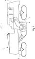
- Fig. 1 shows a construction machine 1 in the form of a large milling machine.
- the construction machine 1 can also be any other construction machine with a drive train in which a clutch is arranged.
- the illustrated construction machine 1 has landing gears 2, which carry a machine frame 4.
- a work roll 6 is mounted as a working device for processing a floor covering 3.
- the work roll 6 may have 3 not shown for machining the floor covering 3 chisel on the lateral surface of the work roll 6.
- the machine frame 4 may be height adjustable via the chassis 2.
- the trolleys can be wheels or crawler tracks.
- the construction machine 1 may further comprise a conveyor, not shown, for removing the milled material.
- the drive train 8 drives the work roll 6.
- the drive train 8 has at least one clutch 14.
- the construction machine 1 may be a milling machine, in particular a road milling machine, a recycler or stabilizer or a surfaceminer.
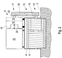
- Fig. 2 schematically shows a cross section through a construction machine 1 with a work roll 6, which is mounted in a machine frame 4.
- the work roll 6 may be mounted in a roll housing, which in turn is fixedly connected to the machine frame 4.
- the work roll 6 can also be movably mounted, in particular height-adjustable relative to the machine frame 4.
- the work roll 6 may for example consist of a milling drum.
- the drive train 8 is shown.
- the drive unit 10 is shown. This may preferably have an internal combustion engine.
- the internal combustion engine may in particular be a diesel engine.
- the drive unit 10 may be coupled via an articulated coupling device, for example an elastomer coupling 20 with a pump distribution gear 16 for driving hydraulic units, such as hydraulic pumps 18.
- the elastomeric coupling 20 can also be arranged elsewhere within the drive train 8.
- the drive train 8 has a clutch 14, which is arranged in the drive train 8 between the drive unit 10 and the work roll 6.
- the clutch 14 is a means for switching the torque.
- a traction mechanism 12 is arranged for the mechanical drive of the work roll 6.
- the traction mechanism 12 has a drive element 11 which is rotatably coupled to an output shaft 22 of the clutch 14.
- the traction mechanism 12 has an output element 13 which is rotatably coupled to a drive shaft 15 of the work roll 6.
- a gear, in particular a planetary gear can be arranged between the drive shaft 15 and the work roll 6, a gear, in particular a planetary gear can be arranged.
- the traction mechanism 12 is preferably a belt drive, wherein the drive and output elements consist of pulleys 11, 13, over which at least one drive belt 30 rotates.
- the drive unit 10 or the pump distribution gearbox 16 can be coupled to the pulley 11 via the clutch 14.
- the clutch 14 is shown in more detail.
- the clutch 14 is preferably a hydraulic clutch.
- the clutch 14 has a drive-side end 58 and a driven-side end 60. Further, an output shaft 22 is provided, wherein on the drive-side end, a drive-side bearing 40 is arranged for the output shaft 22.
- a lubricant line 42 for lubricating the drive-side bearing 40 is provided, which leads from the output-side end 60 to the drive-side bearing 40 and extends at least in sections through the output shaft 22.
- the lubricant line runs, as shown, concentrically in the output shaft 22.
- the lubricant line 42 could also be eccentric to the output shaft 22.
- the illustrated hydraulic clutch 14 further includes a hydraulic line 48 for switching the clutch 14.
- This hydraulic line 48 extends at least partially within the output shaft 22.
- the hydraulic line 48 extends in particular concentrically in the output shaft 22.
- the lubricant line 42 extends at least partially in the hydraulic line 48.
- the first part 46 of the lubricant line 42 extends in this case in the hydraulic line 48.
- a rod-shaped device 44 is provided which extends within the hydraulic line 48 and in which the first part 46 of the lubricant line 42 is arranged is.
- the output end 60 of the lubricant line 42 is closed by a cover member 56.
- the lid member 56 is detachable in a maintenance state, so that in this case the lubricant line 42 can be connected to a lubricant supply.
- the cover member 56 is configured as a rotary feedthrough, which has a passage for hydraulic fluid for the hydraulic line 48.
- the hydraulic line 48 can then be connected to a hydraulic supply by the cover element.
- Fig. 4 the rod-shaped device 44 is shown in more detail.
- This has a head part 50, which is arranged at one end of the rod-shaped device 44.
- the head part 50 is followed by a rod-shaped element 45.
- the rod-shaped element 45 and the head part 50 the lubricant line 42 and the first part 46 of the lubricant line runs.
- the head part 50 has additional passages 54 for the hydraulic fluid.
- a thread 52 is arranged, which can be screwed into the second part 43 of the lubricant line 42.
- Fig. 5 shows the clutch 14 in the operating state.
- hydraulic fluid is passed through the rotary union and through the head part 50 of the rod-shaped device 44 in the hydraulic line 48 through the lid member 56, which is a rotary feedthrough in the illustrated embodiment, during operation.
- the hydraulic clutch 14 can be switched.
- the flow direction of the hydraulic fluid is indicated by the arrows 62.
- the hydraulic line 48 At the transition between the first part 46 of the lubricant line 42 and the second part 43 of the lubricant line 42 is the hydraulic line 48 through the rod-shaped device 44, which is screwed at this end with the thread 52 in the second part 43, closed.
- the hydraulic line 48 and the lubricant line 42 are separated from each other, so that no hydraulic fluid can get into the lubricant line 42 and no lubricant can get into the hydraulic line 48.
- Fig. 6 is a maintenance condition of the clutch 14 is shown.
- the lid member 56 is removed.
- the lubricant line 42 may in this case be connected to a lubricant supply 64.
- the hydraulic clutch 14 does not need to be supplied with hydraulic fluid. Therefore, the lid member 56 can be removed.
- Fig. 7 the flow direction of the lubricant is shown with the arrows 66.
- the lubricant may be guided to the drive side bearing 40.
- Fig. 8 is shown alternative embodiment. It is the embodiment of the previous Fign. very similar, but with the difference that instead of the cover member 56, a double rotary feedthrough 68 is arranged. This has at least one passage 70 to the lubricant line 42 and at least one passage 72 to the hydraulic line 48 on.
- the double rotary feedthrough 68 has the advantage that the drive-side bearing 40 can also be lubricated during operation. It can thus be performed by the double rotary feedthrough both hydraulic fluid and lubricant without the acting as a cover double rotary feedthrough 68 must be removed. In this way, the lubrication of the drive-side bearing can be done automatically according to a predetermined schedule without the operation must be interrupted.
- Fig. 9 It is shown how the lubricant passes through the double rotary feedthrough to the drive-side bearing.
- the direction of flow of the lubricant is indicated at 74.
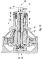
- Fig. 10 It is shown how the hydraulic fluid passes through the double rotary union 68.
- the flow direction of the hydraulic fluid is indicated by the arrows 76.
Landscapes
- Engineering & Computer Science (AREA)
- General Engineering & Computer Science (AREA)
- Mechanical Engineering (AREA)
- Civil Engineering (AREA)
- Structural Engineering (AREA)
- Mining & Mineral Resources (AREA)
- Architecture (AREA)
- Physics & Mathematics (AREA)
- Fluid Mechanics (AREA)
- General Details Of Gearings (AREA)
- Mechanical Operated Clutches (AREA)
- Soil Working Implements (AREA)
Abstract
Description
- Die Erfindung betrifft eine Schaltkupplung für eine Baumaschine nach dem Oberbegriff des Anspruchs 1, sowie eine Baumaschine mit Schaltkupplung nach Anspruch 14.
- Es sind Schaltkupplungen für Baumaschinen bekannt, die im Antriebsstrang einer Baumaschine angeordnet sind. Dabei ist die Schaltkupplung vorzugsweise im Antriebsstrang zwischen dem Antriebsmotor und einer Arbeitseinrichtung, vorzugsweise einer Arbeitswalze in der Baumaschine angeordnet. Die Schaltkupplung weist ein antriebsseitiges Ende und ein abtriebsseitiges Ende auf. Ferner weist die Schaltkupplung eine Abtriebswelle auf, wobei an dem antriebsseitigen Ende ein antriebsseitiges Lager an der Abtriebswelle angeordnet ist.
- Üblicherweise wird dieses antriebsseitige Lager vor Einbau in die Baumaschine einmalig geschmiert. Am antriebsseitigen Ende ist die Schaltkupplung häufig direkt mit anderen Aggregaten des Antriebsstrangs verbunden. Aufgrund der Lage am antriebsseitigen Ende, ist es im eingebauten Zustand daher nur noch mit erheblichen Aufwand möglich, an dieses Lager zu gelangen und weitere Schmierungen vorzunehmen. Dies kann zu einem verfrühten Verschleiß führen.
- Der Erfindung liegt daher die Aufgabe zugrunde, die die Wartung der Schaltkupplung zu vereinfachen und die Lebensdauer der Elemente einer Schaltkupplung für eine Baumaschine zu erhöhen.
- Zur Lösung dieser Aufgabe dienen die Merkmale des Anspruchs 1.
- Die Erfindung sieht in vorteilhafter Weise vor, dass eine Schmiermittelleitung zur Schmierung des antriebsseitigen Lagers vorgesehen ist, die von dem abtriebsseitigen Ende zu dem antriebsseitigen Lager führt und zumindest abschnittsweise durch die Abtriebswelle verläuft.
- Dies hat den Vorteil, dass das antriebsseitige Lager auch vom abtriebsseitigen Ende her geschmiert werden kann. Es ist besonders vorteilhaft, dass zuvor keine oder nur wenige Teile der Schaltkupplung oder anderer Elemente des Antriebsstrangs entfernt werden müssen. Daher kann das Lager in regelmäßigen Abständen geschmiert werden. Dies kann die Lebensdauer dieses Lagers erheblich erhöhen.
- Abschnittsweise bedeutet, dass die Schmiermittelleitung zumindest teilweise durch die Abtriebswelle verläuft.
- Die Schmiermittelleitung kann zumindest abschnittsweise konzentrisch in der Abtriebswelle verlaufen. Es kann dabei insbesondere vorgesehen sein, dass der in der Abtriebswelle verlaufende Abschnitt der Schmiermittelleitung konzentrisch in der Abtriebswelle verläuft.
- Alternativ kann die Schmiermittelleitung zumindest abschnittsweise exzentrisch in der Abtriebswelle verlaufen.
- Die Schaltkupplung kann eine hydraulische Schaltkupplung sein, wobei eine Hydraulikleitung zum Schalten der Schaltkupplung zumindest teilweise innerhalb der Abtriebswelle verläuft.
- Die Hydraulikleitung kann zumindest abschnittsweise konzentrisch in der Abtriebswelle verlaufen. Es kann dabei insbesondere vorgesehen sein, dass der in der Abtriebswelle verlaufende Abschnitt der Hydraulikleitung konzentrisch in der Abtriebswelle verläuft.
- Die Schmiermittelleitung kann zumindest teilweise in der Hydraulikleitung verlaufen.
- Die Schmiermittelleitung kann wenigstens abschnittsweise konzentrisch zu der Hydraulikleitung verlaufen.
- Die Schmiermittelleitung kann durch die gesamte Abtriebswelle verlaufen.
- Die Schmierstoffleitung kann einen ersten Teil aufweisen, der innerhalb einer stabförmigen Einrichtung angeordnet ist, der wiederum in der Hydraulikleitung verläuft.
- Die stabförmige Einrichtung kann zusätzliche Durchlässe für die Hydraulikflüssigkeit aufweisen.
- Das abtriebsseitige Ende der Schmiermittelleitung kann durch ein Deckelelement abgeschlossen sein, wobei das Deckelelement im Wartungszustand beispielsweise zur Durchführung von Wartungsarbeiten von der Schaltkupplung abnehmbar sein kann und somit die Schmiermittelleitung mit einer Schmiermittelversorgung verbunden werden kann. Im Wartungszustand ist die Schaltkupplung vorzugsweise nicht in Betrieb.
- Das Deckelelement kann als Drehdurchführung ausgestaltet sein und einen Durchlass für die Hydraulikleitung aufweisen, so dass im Betriebszustand der Schaltkupplung die Hydraulikleitung durch das Deckelelement mit einer Hydraulikversorgung verbunden ist.
- Das abtriebsseitige Ende der Schmiermittelleitung kann alternativ durch eine doppelte Drehdurchführung abgeschlossen sein, wobei die doppelte Drehdurchführung zumindest einen Durchlass zu der Schmiermittelleitung und zumindest einen Durchlass zu der Hydraulikleitung aufweist.
- Die Schmierung kann dann automatisch beispielsweise durch eine Zentralschmieranlage vorzugsweise nach einem vorgegebenen Zeitplan erfolgen.
- Es kann ferner eine Baumaschine mit Schaltkupplung nach einem der Ansprüche 1 bis 13 vorgesehen sein.
- Im Folgenden werden unter Bezugnahme auf die Zeichnungen Ausführungsbeispiele der Erfindung näher erläutert.
- Es zeigen schematisch:
- Fig. 1
- eine Baumaschine,
- Fig. 2
- einen Antriebsstrang der Baumaschine,
- Fig. 3
- eine Schaltkupplung des Antriebsstrangs,
- Fig. 4
- ein stabförmiges Element der erfindungsgemäßen Schaltkupplung,
- Fig. 5
- die Schaltkupplung gemäß
Fig. 3 im Betriebszustand, - Fig. 6
- die Schaltkupplung gemäß
Fig. 3 in einem Wartungszustand, - Fig. 7
- die Schaltkupplung bei Schmierung des antriebsseitigen Lagers,
- Fig. 8
- eine alternative Schaltkupplung mit doppelter Drehdurchführung,
- Fig. 9
- die Schaltkupplung gemäß
Fig. 8 mit Flussrichtung des Schmiermittels, - Fig. 10
- die Schaltkupplung gemäß
Fig. 8 mit Flussrichtung der Hydraulikfüssigkeit, -
Fig. 1 zeigt eine Baumaschine 1 in Form einer Großfräse. Die Baumaschine 1 kann jedoch auch jegliche andere Baumaschine sein mit einem Antriebsstrang, in dem eine Schaltkupplung angeordnet ist. Die dargestellte Baumaschine 1 weist Fahrwerke 2 auf, die einen Maschinenrahmen 4 tragen. An dem Maschinenrahmen 4 ist eine Arbeitswalze 6 als Arbeitseinrichtung zum Bearbeiten eines Bodenbelags 3 gelagert. Die Arbeitswalze 6 kann zum Bearbeiten des Bodenbelags 3 nicht dargestellte Fräsmeißel an der Mantelfläche der Arbeitswalze 6 aufweisen. - Der Maschinenrahmen 4 kann über die Fahrwerke 2 höhenverstellbar sein. Die Fahrwerke können Räder oder Kettenlaufwerke sein. Die Baumaschine 1 kann ferner eine nicht gezeigte Fördereinrichtung zum Abtransport des Fräsguts aufweisen.
- Der Antriebsstrang 8 treibt die Arbeitswalze 6 an. Der Antriebsstrang 8 weist zumindest eine Schaltkupplung 14 auf.
- Die Baumaschine 1 kann eine Fräsmaschine, insbesondere eine Straßenfräsmaschine, ein Recycler oder Stabilisierer oder ein Surfaceminer sein.
-
Fig. 2 zeigt schematisch einen Querschnitt durch eine Baumaschine 1 mit einer Arbeitswalze 6, die in einem Maschinenrahmen 4 gelagert ist. Alternativ kann die Arbeitswalze 6 in einem Walzengehäuse gelagert sein, das wiederum mit dem Maschinenrahmen 4 fest verbunden ist. Die Arbeitswalze 6 kann auch relativ zu dem Maschinenrahmen 4 beweglich insbesondere höhenverstellbar gelagert sein. Die Arbeitswalze 6 kann beispielsweise aus einer Fräswalze bestehen. - In
Fig. 2 ist der Antriebsstrang 8 dargestellt. InFig. 2 ist die Antriebseinheit 10 dargestellt. Diese kann vorzugsweise einen Verbrennungsmotor aufweisen. Der Verbrennungsmotor kann insbesondere ein Dieselmotor sein. Die Antriebseinheit 10 kann über eine gelenkige Kopplungseinrichtung, beispielsweise eine Elastomerkupplung 20 mit einem Pumpenverteilgetriebe 16 zum Antrieb von hydraulischen Aggregaten, z.B. Hydraulikpumpen 18 gekoppelt sein. Die Elastomerkupplung 20 kann auch an anderer Stelle innerhalb des Antriebstrangs 8 angeordnet sein. - Ferner weist der Antriebstrang 8 eine Schaltkupplung 14 auf, die im Antriebstrang 8 zwischen der Antriebseinheit 10 und der Arbeitswalze 6 angeordnet ist. Die Schaltkupplung 14 ist eine Einrichtung zum Schalten des Drehmoments. Zwischen der Schaltkupplung 14 und der Arbeitswalze 6 ist ein Zugmittelgetriebe 12 für den mechanischen Antrieb der Arbeitswalze 6 angeordnet. Das Zugmittelgetriebe 12 weist ein Antriebselement 11 auf, das mit einer Abtriebswelle 22 der Schaltkupplung 14 drehfest gekoppelt ist. Ferner weist das Zugmittelgetriebe 12 ein Abtriebselement 13 auf, das mit einer Antriebswelle 15 der Arbeitswalze 6 drehfest gekoppelt ist. Zwischen der Antriebswelle 15 und der Arbeitswalze 6 kann noch ein Getriebe insbesondere ein Planetengetriebe angeordnet sein.
- Das Zugmittelgetriebe 12 ist vorzugsweise ein Riemenantrieb, wobei die Antriebs- und Abtriebselemente aus Riemenscheiben 11, 13 bestehen, über die wenigstens ein Antriebsriemen 30 umläuft. Alternativ kann das Zugmittelgetriebe 12 beispielsweise aus einem Kettenantrieb bestehen, wobei dann die Antriebs- und Abtriebselemente aus Ritzeln bestehen.
- Die Antriebseinheit 10 bzw. das Pumpenverteilgetriebe 16 kann über die Schaltkupplung 14 mit der Riemenscheibe 11 gekoppelt sein.
- In
Fig. 3 ist die Schaltkupplung 14 näher dargestellt. Die Schaltkupplung 14 ist vorzugsweise eine hydraulische Schaltkupplung. Die Schaltkupplung 14 weist ein antriebsseitiges Ende 58 und ein abtriebsseitiges Ende 60 auf. Ferner ist eine Abtriebswelle 22 vorgesehen, wobei an dem antriebsseitigen Ende ein antriebsseitiges Lager 40 für die Abtriebswelle 22 angeordnet ist. - Es ist eine Schmiermittelleitung 42 zur Schmierung des antriebsseitigen Lagers 40 vorgesehen, die von dem abtriebsseitigen Ende 60 zu dem antriebsseitigen Lager 40 führt und zumindest abschnittsweise durch die Abtriebswelle 22 verläuft.
- Die Schmiermittelleitung verläuft, wie dargestellt, konzentrisch in der Abtriebswelle 22. Alternativ könnte die Schmiermittelleitung 42 jedoch auch exzentrisch zu der Abtriebswelle 22 verlaufen.
- Die dargestellte hydraulische Schaltkupplung 14 weist ferner eine Hydraulikleitung 48 zum Schalten der Schaltkupplung 14 auf. Diese Hydraulikleitung 48 verläuft zumindest teilweise innerhalb der Abtriebswelle 22. Die Hydraulikleitung 48 verläuft dabei insbesondere konzentrisch in der Abtriebswelle 22. Die Schmiermittelleitung 42 verläuft zumindest teilweise in der Hydraulikleitung 48. Der erste Teil 46 der Schmiermittelleitung 42 verläuft in diesem Fall in der Hydraulikleitung 48. Dafür ist eine stabförmige Einrichtung 44 vorgesehen, die innerhalb der Hydraulikleitung 48 verläuft und in der der erste Teil 46 der Schmiermittelleitung 42 angeordnet ist.
- Das abtriebsseitige Ende 60 der Schmiermittelleitung 42 ist durch ein Deckelelement 56 abgeschlossen. Das Deckelelement 56 ist in einem Wartungszustand abnehmbar, so dass in diesem Fall die Schmiermittelleitung 42 mit einer Schmiermittelversorgung verbunden werden kann.
- Bei dem in
Fig. 3 dargestellten Ausführungsbeispiel ist das Deckelelement 56 als Drehdurchführung ausgestaltet, wobei diese einen Durchlass für Hydraulikflüssigkeit für die Hydraulikleitung 48 aufweist. - In einem Betriebszustand, in dem das Deckelelement 56 die Schmiermittelleitung 42 abschließt, kann dann durch das Deckelelement die Hydraulikleitung 48 mit einer Hydraulikversorgung verbunden sein.
- In
Fig. 4 ist die stabförmige Einrichtung 44 näher dargestellt. Diese weist ein Kopfteil 50 auf, das an einem Ende der stabförmigen Einrichtung 44 angeordnet ist. An das Kopfteil 50 schließt sich ein stabförmiges Element 45 an. Durch das stabförmige Element 45 und das Kopfteil 50 verläuft die Schmiermittelleitung 42 bzw. der erste Teil 46 der Schmiermittelleitung. Ferner weist das Kopfteil 50 zusätzliche Durchlässe 54 für die Hydraulikflüssigkeit auf. An dem dem Kopfteil gegenüberliegenden Ende ist ein Gewinde 52 angeordnet, das in den zweiten Teil 43 der Schmiermittelleitung 42 eingeschraubt werden kann. -
Fig. 5 zeigt die Schaltkupplung 14 im Betriebszustand. Dabei wird durch das Deckelelement 56, das im dargestellten Ausführungsbeispiel eine Drehdurchführung ist, während des Betriebs Hydraulikflüssigkeit durch die Drehdurchführung und durch das Kopfteil 50 der stabförmigen Einrichtung 44 in die Hydraulikleitung 48 geleitet. Mittels der Hydraulikflüssigkeit kann die hydraulische Schaltkupplung 14 geschaltet werden. Die Flussrichtung der Hydraulikflüssigkeit ist mit den Pfeilen 62 gekennzeichnet. Bei dem Übergang zwischen dem ersten Teil 46 der Schmiermittelleitung 42 und dem zweiten Teil 43 der Schmiermittelleitung 42 ist die Hydraulikleitung 48 durch die stabförmige Einrichtung 44, die an diesem Ende mit dem Gewinde 52 in dem zweiten Teil 43 eingeschraubt ist, verschlossen. Die Hydraulikleitung 48 und die Schmiermittelleitung 42 sind voneinander getrennt, so dass keine Hydraulikflüssigkeit in die Schmiermittelleitung 42 gelangen kann und kein Schmiermittel in die Hydraulikleitung 48 gelangen kann. - In
Fig. 6 ist ein Wartungszustand der Schaltkupplung 14 dargestellt. In diesem Wartungszustand ist das Deckelelement 56 abgenommen. Die Schmiermittelleitung 42 kann in diesem Fall mit einer Schmiermittelversorgung 64 verbunden werden. In dem Wartungszustand muss die hydraulische Schaltkupplung 14 nicht mit Hydraulikflüssigkeit versorgt werden. Daher kann das Deckelelement 56 abgenommen werden. - In
Fig. 7 ist die Flussrichtung des Schmiermittels mit den Pfeilen 66 dargestellt. Das Schmiermittel kann zu dem antriebsseitigen Lager 40 geführt werden. - In
Fig. 8 ist alternatives Ausführungsbeispiel dargestellt. Es ist dem Ausführungsbeispiel aus den vorherigen Fign. sehr ähnlich, jedoch mit dem Unterschied, dass anstelle des Deckelelementes 56 eine doppelte Drehdurchführung 68 angeordnet ist. Diese weist zumindest einen Durchlass 70 zu der Schmiermittelleitung 42 und zumindest einen Durchlass 72 zu der Hydraulikleitung 48 auf. Die doppelte Drehdurchführung 68 hat den Vorteil, dass das antriebsseitige Lager 40 auch während des Betriebs geschmiert werden kann. Es kann somit durch die doppelte Drehdurchführung sowohl Hydraulikflüssigkeit als auch Schmiermittel geführt werden, ohne dass die als Deckel fungierende doppelte Drehdurchführung 68 abgenommen werden muss. Auf diese Weise kann die Schmierung des antriebsseitigen Lagers automatisch nach einem vorgegebenen Zeitplan erfolgen ohne dass der Betrieb unterbrochen werden muss. - In
Fig. 9 ist dargestellt, wie das Schmiermittel durch die doppelte Drehdurchführung zu dem antriebsseitigen Lager verläuft. Die Flussrichtung des Schmiermittels ist mit 74 gekennzeichnet. - In
Fig. 10 ist dargestellt, wie die Hydraulikflüssigkeit durch die doppelte Drehdurchführung 68 verläuft. Die Flussrichtung der Hydraulikflüssigkeit ist mit den Pfeilen 76 gekennzeichnet.
Claims (14)
- Schaltkupplung (14) für eine Baumaschine (1), mit- einem antriebsseitigen Ende (58) und einem abtriebsseitigen Ende (60),- einer Abtriebswelle (22), wobei an dem antriebsseitigen Ende (58) ein antriebsseitiges Lager (40) an der Abtriebswelle (22) angeordnet ist,dadurch gekennzeichnet,
dass eine Schmiermittelleitung (42) zur Schmierung des antriebsseitigen Lagers (40) vorgesehen ist, die von dem abtriebsseitigen Ende (60) zu dem antriebsseitigen Lager (40) führt und zumindest abschnittsweise durch die Abtriebswelle (22) verläuft. - Schaltkupplung (14) nach Anspruch 1, dadurch gekennzeichnet, dass die Schmiermittelleitung (42) zumindest abschnittsweise konzentrisch in der Abtriebswelle (22) verläuft.
- Schaltkupplung (14) nach Anspruch 1 oder 2, dadurch gekennzeichnet, dass die Schmiermittelleitung zumindest abschnittsweise exzentrisch in der Abtriebswelle (22) verläuft.
- Schaltkupplung (14) nach einem der Ansprüche 1 bis 3, dadurch gekennzeichnet, dass die Schaltkupplung (14) eine hydraulische Schaltkupplung ist, wobei eine Hydraulikleitung (48) zum Schalten der Schaltkupplung (14) zumindest teilweise innerhalb der Abtriebswelle (22) verläuft.
- Schaltkupplung (14) nach Anspruch 4, dadurch gekennzeichnet, dass die Hydraulikleitung (48) zumindest abschnittsweise konzentrisch in der Abtriebswelle (22) verläuft.
- Schaltkupplung (14) nach Anspruch 4 oder 5, dadurch gekennzeichnet, dass die Schmiermittelleitung (42) zumindest teilweise in der Hydraulikleitung (48) verläuft.
- Schaltkupplung (14) nach ein der Ansprüche 4 bis 6, dadurch gekennzeichnet, dass die Schmiermittelleitung (42) zumindest abschnittsweise konzentrisch zu der Hydraulikleitung (48) verläuft.
- Schaltkupplung (14) nach einem der Ansprüche 4 bis 7, dadurch gekennzeichnet, dass Schmiermittelleitung (42) einen ersten Teil (46) aufweist, der innerhalb einer stabförmigen Einrichtung (44) angeordnet ist, der wiederum in der Hydraulikleitung (48) verläuft.
- Schaltkupplung (14) nach Anspruch 8, dadurch gekennzeichnet, dass die stabförmige Einrichtung (44) zusätzlich Durchlässe (54) für die Hydraulikflüssigkeit aufweist.
- Schaltkupplung (14) nach einem der Ansprüche 1 bis 9, dadurch gekennzeichnet, dass das abtriebsseitige Ende (60) der Schmiermittelleitung (42) durch ein Deckelelement (56) abgeschlossen ist, wobei das Deckelelement (56) in einem Wartungszustand der Schaltkupplung (14) abnehmbar ist und die Schmiermittelleitung (42) mit einer Schmiermittelversorgung (64) verbunden werden kann.
- Schaltkupplung (14) nach Anspruch 10, dadurch gekennzeichnet, dass das Deckelelement (56) als Drehdurchführung ausgestaltet ist und einen Durchlass zu der Hydraulikleitung (48) aufweist, so dass im Betriebszustand der Schaltkupplung (14) die Hydraulikleitung (48) durch das Deckelelement (56) mit einer Hydraulikversorgung verbunden ist.
- Schaltkupplung (14) nach einem der Ansprüche 4 bis 9, dadurch gekennzeichnet, dass das abtriebsseitige Ende (60) der Schmiermittelleitung durch eine doppelte Drehdurchführung (68) abgeschlossen ist, wobei die doppelte Drehdurchführung (68) zumindest einen Durchlass zu der Schmiermittelleitung (42) und zumindest einen Durchlass zu der Hydraulikleitung (48) aufweist.
- Schaltkupplung (14) nach Anspruch 12, dadurch gekennzeichnet, dass die Schmierung automatisch nach einem vorgegebenen Zeitplan erfolgt.
- Baumaschine (1) mit Schaltkupplung (14) nach einem der Ansprüche 1 bis 13.
Applications Claiming Priority (1)
| Application Number | Priority Date | Filing Date | Title |
|---|---|---|---|
| DE102017214939.6A DE102017214939A1 (de) | 2017-08-25 | 2017-08-25 | Schaltkupplung für eine Baumaschine |
Publications (3)
| Publication Number | Publication Date |
|---|---|
| EP3447323A1 true EP3447323A1 (de) | 2019-02-27 |
| EP3447323C0 EP3447323C0 (de) | 2023-09-27 |
| EP3447323B1 EP3447323B1 (de) | 2023-09-27 |
Family
ID=63165252
Family Applications (1)
| Application Number | Title | Priority Date | Filing Date |
|---|---|---|---|
| EP18187464.5A Active EP3447323B1 (de) | 2017-08-25 | 2018-08-06 | Schaltkupplung für eine baumaschine |
Country Status (4)
| Country | Link |
|---|---|
| US (1) | US10900198B2 (de) |
| EP (1) | EP3447323B1 (de) |
| CN (3) | CN109423946A (de) |
| DE (1) | DE102017214939A1 (de) |
Families Citing this family (1)
| Publication number | Priority date | Publication date | Assignee | Title |
|---|---|---|---|---|
| DE102017214939A1 (de) * | 2017-08-25 | 2019-02-28 | Wirtgen Gmbh | Schaltkupplung für eine Baumaschine |
Citations (8)
| Publication number | Priority date | Publication date | Assignee | Title |
|---|---|---|---|---|
| FR1196177A (fr) * | 1958-05-20 | 1959-11-23 | Embrayage pneumatique pour machines-outils | |
| DE1555340A1 (de) * | 1963-10-04 | 1971-02-18 | Ford Werke Ag | Fluessigkeitsdruckbetaetigte Hilfseinrichtung fuer Kupplungen |
| US3823802A (en) * | 1972-08-18 | 1974-07-16 | Caterpillar Tractor Co | Clutch with controlled coolant flow |
| US5009118A (en) * | 1990-03-30 | 1991-04-23 | General Motors Corporation | Power transmission with parallel identical countershafts |
| US5495927A (en) * | 1994-06-24 | 1996-03-05 | General Motors Corporation | Controlled cooling apparatus for torque transfer devices |
| DE19642305A1 (de) * | 1996-10-14 | 1998-04-16 | Zahnradfabrik Friedrichshafen | Schaltbare Kupplung |
| EP2719912A2 (de) * | 2012-10-11 | 2014-04-16 | AGCO International GmbH | Zapfwellenantriebsstränge |
| US9732807B1 (en) * | 2014-06-06 | 2017-08-15 | Logan Clutch Corporation | Clutch assembly and system |
Family Cites Families (17)
| Publication number | Priority date | Publication date | Assignee | Title |
|---|---|---|---|---|
| US2838913A (en) * | 1950-07-15 | 1958-06-17 | Gen Motors Corp | Aircraft power system and clutch control therefor |
| US2924983A (en) * | 1956-06-14 | 1960-02-16 | Danly Mach Specialties Inc | Dual speed clutch assembly |
| US3463283A (en) * | 1966-01-06 | 1969-08-26 | Int Harvester Co | Hydraulic pressure control system for clutches |
| US3833100A (en) * | 1973-01-02 | 1974-09-03 | Twin Disc Inc | Control system for a power transmission clutch |
| US4899861A (en) * | 1987-03-16 | 1990-02-13 | Rockford Powertrain, Inc. | Variable speed drive for engine cooling fans |
| US4947974A (en) * | 1988-01-15 | 1990-08-14 | Deere & Company | Fast fill hydraulic clutch |
| HU216712B (hu) * | 1994-02-24 | 1999-08-30 | RÁBA Magyar Vagon- és Gépgyár Rt. | Speciális olajkeringető rendszer, főként nedvesfékes munkagépfutóművek és nagy terhelésű kerékagy-bolygóműves futóművek hűtésére |
| US5577588A (en) * | 1995-03-17 | 1996-11-26 | General Motors Corporation | Lube assembly for a transmission friction device |
| JPH1030651A (ja) * | 1996-07-16 | 1998-02-03 | Nsk Warner Kk | 発進クラッチの油圧回路 |
| US6701241B2 (en) * | 2000-09-15 | 2004-03-02 | Robert Bosch Gmbh | Method and device for operating a clutch |
| DE102005017754A1 (de) * | 2005-04-15 | 2006-10-19 | Wirtgen Gmbh | Baumaschine insbesondere Strassenfräsmaschine, Recycler oder Stabilisierer, sowie Antriebsstrang für derartige Baumaschinen |
| US20080121488A1 (en) * | 2006-11-27 | 2008-05-29 | Tomoyuki Miyazaki | Starting clutch |
| DE202007010294U1 (de) * | 2007-07-20 | 2008-11-27 | Wirtgen Gmbh | Baumaschine sowie Schaltkupplung zum Schalten des Kraftflusses |
| US7938147B2 (en) * | 2008-11-05 | 2011-05-10 | Allison Transmission, Inc. | Apparatus and method for axially transferring fluids to a plurality of components |
| AU2011317308B2 (en) * | 2010-10-19 | 2016-11-03 | Allison Transmission, Inc. | Face spline clutch |
| MX338570B (es) * | 2012-03-05 | 2016-04-22 | Muncie Power Prod Inc | Aparatos y metodos de lubricacion de toma de fuerza. |
| DE102017214939A1 (de) * | 2017-08-25 | 2019-02-28 | Wirtgen Gmbh | Schaltkupplung für eine Baumaschine |
-
2017
- 2017-08-25 DE DE102017214939.6A patent/DE102017214939A1/de not_active Withdrawn
-
2018
- 2018-08-06 EP EP18187464.5A patent/EP3447323B1/de active Active
- 2018-08-21 US US16/106,465 patent/US10900198B2/en active Active
- 2018-08-22 CN CN201810963033.4A patent/CN109423946A/zh active Pending
- 2018-08-22 CN CN202610131653.6A patent/CN121630970A/zh active Pending
- 2018-08-22 CN CN201821358079.5U patent/CN209227338U/zh active Active
Patent Citations (8)
| Publication number | Priority date | Publication date | Assignee | Title |
|---|---|---|---|---|
| FR1196177A (fr) * | 1958-05-20 | 1959-11-23 | Embrayage pneumatique pour machines-outils | |
| DE1555340A1 (de) * | 1963-10-04 | 1971-02-18 | Ford Werke Ag | Fluessigkeitsdruckbetaetigte Hilfseinrichtung fuer Kupplungen |
| US3823802A (en) * | 1972-08-18 | 1974-07-16 | Caterpillar Tractor Co | Clutch with controlled coolant flow |
| US5009118A (en) * | 1990-03-30 | 1991-04-23 | General Motors Corporation | Power transmission with parallel identical countershafts |
| US5495927A (en) * | 1994-06-24 | 1996-03-05 | General Motors Corporation | Controlled cooling apparatus for torque transfer devices |
| DE19642305A1 (de) * | 1996-10-14 | 1998-04-16 | Zahnradfabrik Friedrichshafen | Schaltbare Kupplung |
| EP2719912A2 (de) * | 2012-10-11 | 2014-04-16 | AGCO International GmbH | Zapfwellenantriebsstränge |
| US9732807B1 (en) * | 2014-06-06 | 2017-08-15 | Logan Clutch Corporation | Clutch assembly and system |
Also Published As
| Publication number | Publication date |
|---|---|
| EP3447323C0 (de) | 2023-09-27 |
| US20190063038A1 (en) | 2019-02-28 |
| DE102017214939A1 (de) | 2019-02-28 |
| US10900198B2 (en) | 2021-01-26 |
| CN121630970A (zh) | 2026-03-10 |
| CN109423946A (zh) | 2019-03-05 |
| EP3447323B1 (de) | 2023-09-27 |
| CN209227338U (zh) | 2019-08-09 |
Similar Documents
| Publication | Publication Date | Title |
|---|---|---|
| DE4238256C2 (de) | Zapfenwellengetriebe mit einer Schmiereinrichtung | |
| DE3028490C2 (de) | Stufenlos einstellbares Kegelscheibengetriebe | |
| DE102015207612B4 (de) | Schmiersystem und ein solches umfassendes Verteilergetriebe | |
| DE102012024770B4 (de) | Selbstfahrende Baumaschine | |
| DE1949973C3 (de) | Hydrostatisches Aggregat | |
| DE102011011867A1 (de) | Getriebe für einen Schienfahrzeugantriebsstrang | |
| DE4216703B4 (de) | Getriebeanordnung für ein Fahrzeug | |
| EP3447323B1 (de) | Schaltkupplung für eine baumaschine | |
| EP3365497B1 (de) | Antriebseinrichtung für eine baumaschine, sowie baumaschine | |
| DE2361022A1 (de) | Bremsanordnung fuer den schwenkantrieb eines baggers | |
| EP2448794B1 (de) | Kraftfahrzeuggetriebe mit hydrodynamischem retarder | |
| DE102004032227A1 (de) | Schmierungsstruktur eines Handschaltgetriebes | |
| DE2519115A1 (de) | Getriebe | |
| EP3289244B1 (de) | Arbeitsmaschine mit leistungsverzweigbarem antrieb | |
| DE102014108007B4 (de) | Wellenflansch einer landwirtschaftlichen Erntemaschine | |
| DE2819200C2 (de) | ||
| DE102016013288A1 (de) | Kraftfahrzeug für vielfältigen Einsatz | |
| DE102011118111A1 (de) | Antriebsstrang für einen Kraftwagen | |
| EP3215762B1 (de) | Antriebseinrichtung für ein kraftfahrzeug | |
| EP3434550B1 (de) | Antriebsanordnung | |
| DE102014203435A1 (de) | Ölpumpenantrieb | |
| DE202011051421U1 (de) | Antriebsvorrichtung einer Schneckenzentrifuge | |
| DE102022205091B3 (de) | Getriebe und Antriebsstrang | |
| DE2553010A1 (de) | Fahrzeuggetriebe | |
| DE4308113A1 (de) | Antriebsanordnung für Nebenaggregate |
Legal Events
| Date | Code | Title | Description |
|---|---|---|---|
| PUAI | Public reference made under article 153(3) epc to a published international application that has entered the european phase |
Free format text: ORIGINAL CODE: 0009012 |
|
| STAA | Information on the status of an ep patent application or granted ep patent |
Free format text: STATUS: THE APPLICATION HAS BEEN PUBLISHED |
|
| AK | Designated contracting states |
Kind code of ref document: A1 Designated state(s): AL AT BE BG CH CY CZ DE DK EE ES FI FR GB GR HR HU IE IS IT LI LT LU LV MC MK MT NL NO PL PT RO RS SE SI SK SM TR |
|
| AX | Request for extension of the european patent |
Extension state: BA ME |
|
| STAA | Information on the status of an ep patent application or granted ep patent |
Free format text: STATUS: REQUEST FOR EXAMINATION WAS MADE |
|
| 17P | Request for examination filed |
Effective date: 20190827 |
|
| RBV | Designated contracting states (corrected) |
Designated state(s): AL AT BE BG CH CY CZ DE DK EE ES FI FR GB GR HR HU IE IS IT LI LT LU LV MC MK MT NL NO PL PT RO RS SE SI SK SM TR |
|
| STAA | Information on the status of an ep patent application or granted ep patent |
Free format text: STATUS: EXAMINATION IS IN PROGRESS |
|
| 17Q | First examination report despatched |
Effective date: 20191115 |
|
| GRAP | Despatch of communication of intention to grant a patent |
Free format text: ORIGINAL CODE: EPIDOSNIGR1 |
|
| STAA | Information on the status of an ep patent application or granted ep patent |
Free format text: STATUS: GRANT OF PATENT IS INTENDED |
|
| INTG | Intention to grant announced |
Effective date: 20230327 |
|
| P01 | Opt-out of the competence of the unified patent court (upc) registered |
Effective date: 20230527 |
|
| GRAS | Grant fee paid |
Free format text: ORIGINAL CODE: EPIDOSNIGR3 |
|
| GRAA | (expected) grant |
Free format text: ORIGINAL CODE: 0009210 |
|
| STAA | Information on the status of an ep patent application or granted ep patent |
Free format text: STATUS: THE PATENT HAS BEEN GRANTED |
|
| AK | Designated contracting states |
Kind code of ref document: B1 Designated state(s): AL AT BE BG CH CY CZ DE DK EE ES FI FR GB GR HR HU IE IS IT LI LT LU LV MC MK MT NL NO PL PT RO RS SE SI SK SM TR |
|
| REG | Reference to a national code |
Ref country code: GB Ref legal event code: FG4D Free format text: NOT ENGLISH |
|
| REG | Reference to a national code |
Ref country code: CH Ref legal event code: EP |
|
| REG | Reference to a national code |
Ref country code: DE Ref legal event code: R096 Ref document number: 502018013308 Country of ref document: DE |
|
| REG | Reference to a national code |
Ref country code: IE Ref legal event code: FG4D Free format text: LANGUAGE OF EP DOCUMENT: GERMAN |
|
| P04 | Withdrawal of opt-out of the competence of the unified patent court (upc) registered |
Effective date: 20231030 |
|
| U01 | Request for unitary effect filed |
Effective date: 20231027 |
|
| U07 | Unitary effect registered |
Designated state(s): AT BE BG DE DK EE FI FR IT LT LU LV MT NL PT SE SI Effective date: 20231102 |
|
| PG25 | Lapsed in a contracting state [announced via postgrant information from national office to epo] |
Ref country code: GR Free format text: LAPSE BECAUSE OF FAILURE TO SUBMIT A TRANSLATION OF THE DESCRIPTION OR TO PAY THE FEE WITHIN THE PRESCRIBED TIME-LIMIT Effective date: 20231228 |
|
| PG25 | Lapsed in a contracting state [announced via postgrant information from national office to epo] |
Ref country code: RS Free format text: LAPSE BECAUSE OF FAILURE TO SUBMIT A TRANSLATION OF THE DESCRIPTION OR TO PAY THE FEE WITHIN THE PRESCRIBED TIME-LIMIT Effective date: 20230927 Ref country code: NO Free format text: LAPSE BECAUSE OF FAILURE TO SUBMIT A TRANSLATION OF THE DESCRIPTION OR TO PAY THE FEE WITHIN THE PRESCRIBED TIME-LIMIT Effective date: 20231227 Ref country code: HR Free format text: LAPSE BECAUSE OF FAILURE TO SUBMIT A TRANSLATION OF THE DESCRIPTION OR TO PAY THE FEE WITHIN THE PRESCRIBED TIME-LIMIT Effective date: 20230927 Ref country code: GR Free format text: LAPSE BECAUSE OF FAILURE TO SUBMIT A TRANSLATION OF THE DESCRIPTION OR TO PAY THE FEE WITHIN THE PRESCRIBED TIME-LIMIT Effective date: 20231228 |
|
| PG25 | Lapsed in a contracting state [announced via postgrant information from national office to epo] |
Ref country code: IS Free format text: LAPSE BECAUSE OF FAILURE TO SUBMIT A TRANSLATION OF THE DESCRIPTION OR TO PAY THE FEE WITHIN THE PRESCRIBED TIME-LIMIT Effective date: 20240127 |
|
| PG25 | Lapsed in a contracting state [announced via postgrant information from national office to epo] |
Ref country code: ES Free format text: LAPSE BECAUSE OF FAILURE TO SUBMIT A TRANSLATION OF THE DESCRIPTION OR TO PAY THE FEE WITHIN THE PRESCRIBED TIME-LIMIT Effective date: 20230927 |
|
| PG25 | Lapsed in a contracting state [announced via postgrant information from national office to epo] |
Ref country code: SM Free format text: LAPSE BECAUSE OF FAILURE TO SUBMIT A TRANSLATION OF THE DESCRIPTION OR TO PAY THE FEE WITHIN THE PRESCRIBED TIME-LIMIT Effective date: 20230927 Ref country code: RO Free format text: LAPSE BECAUSE OF FAILURE TO SUBMIT A TRANSLATION OF THE DESCRIPTION OR TO PAY THE FEE WITHIN THE PRESCRIBED TIME-LIMIT Effective date: 20230927 Ref country code: IS Free format text: LAPSE BECAUSE OF FAILURE TO SUBMIT A TRANSLATION OF THE DESCRIPTION OR TO PAY THE FEE WITHIN THE PRESCRIBED TIME-LIMIT Effective date: 20240127 Ref country code: ES Free format text: LAPSE BECAUSE OF FAILURE TO SUBMIT A TRANSLATION OF THE DESCRIPTION OR TO PAY THE FEE WITHIN THE PRESCRIBED TIME-LIMIT Effective date: 20230927 Ref country code: CZ Free format text: LAPSE BECAUSE OF FAILURE TO SUBMIT A TRANSLATION OF THE DESCRIPTION OR TO PAY THE FEE WITHIN THE PRESCRIBED TIME-LIMIT Effective date: 20230927 Ref country code: SK Free format text: LAPSE BECAUSE OF FAILURE TO SUBMIT A TRANSLATION OF THE DESCRIPTION OR TO PAY THE FEE WITHIN THE PRESCRIBED TIME-LIMIT Effective date: 20230927 |
|
| PG25 | Lapsed in a contracting state [announced via postgrant information from national office to epo] |
Ref country code: PL Free format text: LAPSE BECAUSE OF FAILURE TO SUBMIT A TRANSLATION OF THE DESCRIPTION OR TO PAY THE FEE WITHIN THE PRESCRIBED TIME-LIMIT Effective date: 20230927 |
|
| REG | Reference to a national code |
Ref country code: DE Ref legal event code: R097 Ref document number: 502018013308 Country of ref document: DE |
|
| PLBE | No opposition filed within time limit |
Free format text: ORIGINAL CODE: 0009261 |
|
| STAA | Information on the status of an ep patent application or granted ep patent |
Free format text: STATUS: NO OPPOSITION FILED WITHIN TIME LIMIT |
|
| 26N | No opposition filed |
Effective date: 20240628 |
|
| U20 | Renewal fee for the european patent with unitary effect paid |
Year of fee payment: 7 Effective date: 20240814 |
|
| P05 | Withdrawal of opt-out of the competence of the unified patent court (upc) changed |
Free format text: CASE NUMBER: APP_584236/2023 Effective date: 20231102 |
|
| REG | Reference to a national code |
Ref country code: CH Ref legal event code: PL |
|
| GBPC | Gb: european patent ceased through non-payment of renewal fee |
Effective date: 20240806 |
|
| PG25 | Lapsed in a contracting state [announced via postgrant information from national office to epo] |
Ref country code: CH Free format text: LAPSE BECAUSE OF NON-PAYMENT OF DUE FEES Effective date: 20240831 Ref country code: MC Free format text: LAPSE BECAUSE OF FAILURE TO SUBMIT A TRANSLATION OF THE DESCRIPTION OR TO PAY THE FEE WITHIN THE PRESCRIBED TIME-LIMIT Effective date: 20230927 |
|
| PG25 | Lapsed in a contracting state [announced via postgrant information from national office to epo] |
Ref country code: GB Free format text: LAPSE BECAUSE OF NON-PAYMENT OF DUE FEES Effective date: 20240806 |
|
| PG25 | Lapsed in a contracting state [announced via postgrant information from national office to epo] |
Ref country code: IE Free format text: LAPSE BECAUSE OF NON-PAYMENT OF DUE FEES Effective date: 20240806 |
|
| U20 | Renewal fee for the european patent with unitary effect paid |
Year of fee payment: 8 Effective date: 20250826 |
|
| PG25 | Lapsed in a contracting state [announced via postgrant information from national office to epo] |
Ref country code: CY Free format text: LAPSE BECAUSE OF FAILURE TO SUBMIT A TRANSLATION OF THE DESCRIPTION OR TO PAY THE FEE WITHIN THE PRESCRIBED TIME-LIMIT; INVALID AB INITIO Effective date: 20180806 |
|
| PG25 | Lapsed in a contracting state [announced via postgrant information from national office to epo] |
Ref country code: HU Free format text: LAPSE BECAUSE OF FAILURE TO SUBMIT A TRANSLATION OF THE DESCRIPTION OR TO PAY THE FEE WITHIN THE PRESCRIBED TIME-LIMIT; INVALID AB INITIO Effective date: 20180806 |