EP3446855B1 - Vorrichtung zur generativen fertigung von dreidimensionalen objekten - Google Patents
Vorrichtung zur generativen fertigung von dreidimensionalen objekten Download PDFInfo
- Publication number
- EP3446855B1 EP3446855B1 EP17187997.6A EP17187997A EP3446855B1 EP 3446855 B1 EP3446855 B1 EP 3446855B1 EP 17187997 A EP17187997 A EP 17187997A EP 3446855 B1 EP3446855 B1 EP 3446855B1
- Authority
- EP
- European Patent Office
- Prior art keywords
- zone
- radiation
- energy beam
- consolidation
- temperature
- Prior art date
- Legal status (The legal status is an assumption and is not a legal conclusion. Google has not performed a legal analysis and makes no representation as to the accuracy of the status listed.)
- Active
Links
- 238000004519 manufacturing process Methods 0.000 title claims description 16
- 238000007596 consolidation process Methods 0.000 claims description 83
- 230000005855 radiation Effects 0.000 claims description 73
- 239000000463 material Substances 0.000 claims description 50
- 238000001514 detection method Methods 0.000 claims description 48
- 230000003287 optical effect Effects 0.000 claims description 36
- 238000000034 method Methods 0.000 claims description 28
- 230000008569 process Effects 0.000 claims description 19
- 230000001419 dependent effect Effects 0.000 claims description 16
- 239000011521 glass Substances 0.000 claims description 9
- 230000001681 protective effect Effects 0.000 claims description 9
- 238000000411 transmission spectrum Methods 0.000 claims description 4
- 230000001360 synchronised effect Effects 0.000 claims description 3
- 238000013500 data storage Methods 0.000 claims description 2
- 238000010438 heat treatment Methods 0.000 description 9
- 238000001228 spectrum Methods 0.000 description 5
- 239000012530 fluid Substances 0.000 description 4
- 230000000694 effects Effects 0.000 description 3
- 238000003384 imaging method Methods 0.000 description 3
- 238000002844 melting Methods 0.000 description 3
- 230000008018 melting Effects 0.000 description 3
- XKRFYHLGVUSROY-UHFFFAOYSA-N Argon Chemical compound [Ar] XKRFYHLGVUSROY-UHFFFAOYSA-N 0.000 description 2
- IJGRMHOSHXDMSA-UHFFFAOYSA-N Atomic nitrogen Chemical compound N#N IJGRMHOSHXDMSA-UHFFFAOYSA-N 0.000 description 2
- CURLTUGMZLYLDI-UHFFFAOYSA-N Carbon dioxide Chemical compound O=C=O CURLTUGMZLYLDI-UHFFFAOYSA-N 0.000 description 2
- 238000004458 analytical method Methods 0.000 description 2
- 238000000576 coating method Methods 0.000 description 2
- 239000007789 gas Substances 0.000 description 2
- 238000012544 monitoring process Methods 0.000 description 2
- 239000000779 smoke Substances 0.000 description 2
- XLYOFNOQVPJJNP-UHFFFAOYSA-N water Substances O XLYOFNOQVPJJNP-UHFFFAOYSA-N 0.000 description 2
- 239000000654 additive Substances 0.000 description 1
- 230000000996 additive effect Effects 0.000 description 1
- 229910052786 argon Inorganic materials 0.000 description 1
- 238000000149 argon plasma sintering Methods 0.000 description 1
- 239000001569 carbon dioxide Substances 0.000 description 1
- 229910002092 carbon dioxide Inorganic materials 0.000 description 1
- 239000000919 ceramic Substances 0.000 description 1
- 230000008859 change Effects 0.000 description 1
- 230000007547 defect Effects 0.000 description 1
- 238000010586 diagram Methods 0.000 description 1
- 238000010894 electron beam technology Methods 0.000 description 1
- 230000008020 evaporation Effects 0.000 description 1
- 238000001704 evaporation Methods 0.000 description 1
- 238000001914 filtration Methods 0.000 description 1
- 230000004907 flux Effects 0.000 description 1
- 230000001939 inductive effect Effects 0.000 description 1
- 239000011261 inert gas Substances 0.000 description 1
- 230000002452 interceptive effect Effects 0.000 description 1
- 230000001678 irradiating effect Effects 0.000 description 1
- 238000007726 management method Methods 0.000 description 1
- 239000002184 metal Substances 0.000 description 1
- 229910052757 nitrogen Inorganic materials 0.000 description 1
- 229920000642 polymer Polymers 0.000 description 1
- 239000000843 powder Substances 0.000 description 1
- 238000004886 process control Methods 0.000 description 1
- 230000002441 reversible effect Effects 0.000 description 1
- 238000000110 selective laser sintering Methods 0.000 description 1
- 238000003860 storage Methods 0.000 description 1
Images
Classifications
-
- B—PERFORMING OPERATIONS; TRANSPORTING
- B22—CASTING; POWDER METALLURGY
- B22F—WORKING METALLIC POWDER; MANUFACTURE OF ARTICLES FROM METALLIC POWDER; MAKING METALLIC POWDER; APPARATUS OR DEVICES SPECIALLY ADAPTED FOR METALLIC POWDER
- B22F10/00—Additive manufacturing of workpieces or articles from metallic powder
-
- B—PERFORMING OPERATIONS; TRANSPORTING
- B29—WORKING OF PLASTICS; WORKING OF SUBSTANCES IN A PLASTIC STATE IN GENERAL
- B29C—SHAPING OR JOINING OF PLASTICS; SHAPING OF MATERIAL IN A PLASTIC STATE, NOT OTHERWISE PROVIDED FOR; AFTER-TREATMENT OF THE SHAPED PRODUCTS, e.g. REPAIRING
- B29C64/00—Additive manufacturing, i.e. manufacturing of three-dimensional [3D] objects by additive deposition, additive agglomeration or additive layering, e.g. by 3D printing, stereolithography or selective laser sintering
- B29C64/10—Processes of additive manufacturing
- B29C64/141—Processes of additive manufacturing using only solid materials
- B29C64/153—Processes of additive manufacturing using only solid materials using layers of powder being selectively joined, e.g. by selective laser sintering or melting
-
- B—PERFORMING OPERATIONS; TRANSPORTING
- B22—CASTING; POWDER METALLURGY
- B22F—WORKING METALLIC POWDER; MANUFACTURE OF ARTICLES FROM METALLIC POWDER; MAKING METALLIC POWDER; APPARATUS OR DEVICES SPECIALLY ADAPTED FOR METALLIC POWDER
- B22F10/00—Additive manufacturing of workpieces or articles from metallic powder
- B22F10/20—Direct sintering or melting
- B22F10/28—Powder bed fusion, e.g. selective laser melting [SLM] or electron beam melting [EBM]
-
- B—PERFORMING OPERATIONS; TRANSPORTING
- B22—CASTING; POWDER METALLURGY
- B22F—WORKING METALLIC POWDER; MANUFACTURE OF ARTICLES FROM METALLIC POWDER; MAKING METALLIC POWDER; APPARATUS OR DEVICES SPECIALLY ADAPTED FOR METALLIC POWDER
- B22F12/00—Apparatus or devices specially adapted for additive manufacturing; Auxiliary means for additive manufacturing; Combinations of additive manufacturing apparatus or devices with other processing apparatus or devices
- B22F12/90—Means for process control, e.g. cameras or sensors
-
- B—PERFORMING OPERATIONS; TRANSPORTING
- B23—MACHINE TOOLS; METAL-WORKING NOT OTHERWISE PROVIDED FOR
- B23K—SOLDERING OR UNSOLDERING; WELDING; CLADDING OR PLATING BY SOLDERING OR WELDING; CUTTING BY APPLYING HEAT LOCALLY, e.g. FLAME CUTTING; WORKING BY LASER BEAM
- B23K26/00—Working by laser beam, e.g. welding, cutting or boring
- B23K26/34—Laser welding for purposes other than joining
-
- B—PERFORMING OPERATIONS; TRANSPORTING
- B23—MACHINE TOOLS; METAL-WORKING NOT OTHERWISE PROVIDED FOR
- B23K—SOLDERING OR UNSOLDERING; WELDING; CLADDING OR PLATING BY SOLDERING OR WELDING; CUTTING BY APPLYING HEAT LOCALLY, e.g. FLAME CUTTING; WORKING BY LASER BEAM
- B23K26/00—Working by laser beam, e.g. welding, cutting or boring
- B23K26/352—Working by laser beam, e.g. welding, cutting or boring for surface treatment
- B23K26/354—Working by laser beam, e.g. welding, cutting or boring for surface treatment by melting
-
- B—PERFORMING OPERATIONS; TRANSPORTING
- B29—WORKING OF PLASTICS; WORKING OF SUBSTANCES IN A PLASTIC STATE IN GENERAL
- B29C—SHAPING OR JOINING OF PLASTICS; SHAPING OF MATERIAL IN A PLASTIC STATE, NOT OTHERWISE PROVIDED FOR; AFTER-TREATMENT OF THE SHAPED PRODUCTS, e.g. REPAIRING
- B29C64/00—Additive manufacturing, i.e. manufacturing of three-dimensional [3D] objects by additive deposition, additive agglomeration or additive layering, e.g. by 3D printing, stereolithography or selective laser sintering
- B29C64/10—Processes of additive manufacturing
- B29C64/106—Processes of additive manufacturing using only liquids or viscous materials, e.g. depositing a continuous bead of viscous material
- B29C64/124—Processes of additive manufacturing using only liquids or viscous materials, e.g. depositing a continuous bead of viscous material using layers of liquid which are selectively solidified
- B29C64/129—Processes of additive manufacturing using only liquids or viscous materials, e.g. depositing a continuous bead of viscous material using layers of liquid which are selectively solidified characterised by the energy source therefor, e.g. by global irradiation combined with a mask
- B29C64/135—Processes of additive manufacturing using only liquids or viscous materials, e.g. depositing a continuous bead of viscous material using layers of liquid which are selectively solidified characterised by the energy source therefor, e.g. by global irradiation combined with a mask the energy source being concentrated, e.g. scanning lasers or focused light sources
-
- B—PERFORMING OPERATIONS; TRANSPORTING
- B29—WORKING OF PLASTICS; WORKING OF SUBSTANCES IN A PLASTIC STATE IN GENERAL
- B29C—SHAPING OR JOINING OF PLASTICS; SHAPING OF MATERIAL IN A PLASTIC STATE, NOT OTHERWISE PROVIDED FOR; AFTER-TREATMENT OF THE SHAPED PRODUCTS, e.g. REPAIRING
- B29C64/00—Additive manufacturing, i.e. manufacturing of three-dimensional [3D] objects by additive deposition, additive agglomeration or additive layering, e.g. by 3D printing, stereolithography or selective laser sintering
- B29C64/30—Auxiliary operations or equipment
- B29C64/386—Data acquisition or data processing for additive manufacturing
- B29C64/393—Data acquisition or data processing for additive manufacturing for controlling or regulating additive manufacturing processes
-
- B—PERFORMING OPERATIONS; TRANSPORTING
- B33—ADDITIVE MANUFACTURING TECHNOLOGY
- B33Y—ADDITIVE MANUFACTURING, i.e. MANUFACTURING OF THREE-DIMENSIONAL [3-D] OBJECTS BY ADDITIVE DEPOSITION, ADDITIVE AGGLOMERATION OR ADDITIVE LAYERING, e.g. BY 3-D PRINTING, STEREOLITHOGRAPHY OR SELECTIVE LASER SINTERING
- B33Y10/00—Processes of additive manufacturing
-
- B—PERFORMING OPERATIONS; TRANSPORTING
- B33—ADDITIVE MANUFACTURING TECHNOLOGY
- B33Y—ADDITIVE MANUFACTURING, i.e. MANUFACTURING OF THREE-DIMENSIONAL [3-D] OBJECTS BY ADDITIVE DEPOSITION, ADDITIVE AGGLOMERATION OR ADDITIVE LAYERING, e.g. BY 3-D PRINTING, STEREOLITHOGRAPHY OR SELECTIVE LASER SINTERING
- B33Y30/00—Apparatus for additive manufacturing; Details thereof or accessories therefor
-
- B—PERFORMING OPERATIONS; TRANSPORTING
- B33—ADDITIVE MANUFACTURING TECHNOLOGY
- B33Y—ADDITIVE MANUFACTURING, i.e. MANUFACTURING OF THREE-DIMENSIONAL [3-D] OBJECTS BY ADDITIVE DEPOSITION, ADDITIVE AGGLOMERATION OR ADDITIVE LAYERING, e.g. BY 3-D PRINTING, STEREOLITHOGRAPHY OR SELECTIVE LASER SINTERING
- B33Y50/00—Data acquisition or data processing for additive manufacturing
- B33Y50/02—Data acquisition or data processing for additive manufacturing for controlling or regulating additive manufacturing processes
-
- C—CHEMISTRY; METALLURGY
- C04—CEMENTS; CONCRETE; ARTIFICIAL STONE; CERAMICS; REFRACTORIES
- C04B—LIME, MAGNESIA; SLAG; CEMENTS; COMPOSITIONS THEREOF, e.g. MORTARS, CONCRETE OR LIKE BUILDING MATERIALS; ARTIFICIAL STONE; CERAMICS; REFRACTORIES; TREATMENT OF NATURAL STONE
- C04B35/00—Shaped ceramic products characterised by their composition; Ceramics compositions; Processing powders of inorganic compounds preparatory to the manufacturing of ceramic products
- C04B35/622—Forming processes; Processing powders of inorganic compounds preparatory to the manufacturing of ceramic products
- C04B35/64—Burning or sintering processes
-
- B—PERFORMING OPERATIONS; TRANSPORTING
- B22—CASTING; POWDER METALLURGY
- B22F—WORKING METALLIC POWDER; MANUFACTURE OF ARTICLES FROM METALLIC POWDER; MAKING METALLIC POWDER; APPARATUS OR DEVICES SPECIALLY ADAPTED FOR METALLIC POWDER
- B22F10/00—Additive manufacturing of workpieces or articles from metallic powder
- B22F10/30—Process control
- B22F10/32—Process control of the atmosphere, e.g. composition or pressure in a building chamber
-
- B—PERFORMING OPERATIONS; TRANSPORTING
- B22—CASTING; POWDER METALLURGY
- B22F—WORKING METALLIC POWDER; MANUFACTURE OF ARTICLES FROM METALLIC POWDER; MAKING METALLIC POWDER; APPARATUS OR DEVICES SPECIALLY ADAPTED FOR METALLIC POWDER
- B22F10/00—Additive manufacturing of workpieces or articles from metallic powder
- B22F10/30—Process control
- B22F10/36—Process control of energy beam parameters
- B22F10/368—Temperature or temperature gradient, e.g. temperature of the melt pool
-
- B—PERFORMING OPERATIONS; TRANSPORTING
- B22—CASTING; POWDER METALLURGY
- B22F—WORKING METALLIC POWDER; MANUFACTURE OF ARTICLES FROM METALLIC POWDER; MAKING METALLIC POWDER; APPARATUS OR DEVICES SPECIALLY ADAPTED FOR METALLIC POWDER
- B22F12/00—Apparatus or devices specially adapted for additive manufacturing; Auxiliary means for additive manufacturing; Combinations of additive manufacturing apparatus or devices with other processing apparatus or devices
- B22F12/40—Radiation means
- B22F12/49—Scanners
-
- B—PERFORMING OPERATIONS; TRANSPORTING
- B22—CASTING; POWDER METALLURGY
- B22F—WORKING METALLIC POWDER; MANUFACTURE OF ARTICLES FROM METALLIC POWDER; MAKING METALLIC POWDER; APPARATUS OR DEVICES SPECIALLY ADAPTED FOR METALLIC POWDER
- B22F12/00—Apparatus or devices specially adapted for additive manufacturing; Auxiliary means for additive manufacturing; Combinations of additive manufacturing apparatus or devices with other processing apparatus or devices
- B22F12/70—Gas flow means
-
- B—PERFORMING OPERATIONS; TRANSPORTING
- B29—WORKING OF PLASTICS; WORKING OF SUBSTANCES IN A PLASTIC STATE IN GENERAL
- B29C—SHAPING OR JOINING OF PLASTICS; SHAPING OF MATERIAL IN A PLASTIC STATE, NOT OTHERWISE PROVIDED FOR; AFTER-TREATMENT OF THE SHAPED PRODUCTS, e.g. REPAIRING
- B29C64/00—Additive manufacturing, i.e. manufacturing of three-dimensional [3D] objects by additive deposition, additive agglomeration or additive layering, e.g. by 3D printing, stereolithography or selective laser sintering
- B29C64/20—Apparatus for additive manufacturing; Details thereof or accessories therefor
- B29C64/264—Arrangements for irradiation
-
- C—CHEMISTRY; METALLURGY
- C04—CEMENTS; CONCRETE; ARTIFICIAL STONE; CERAMICS; REFRACTORIES
- C04B—LIME, MAGNESIA; SLAG; CEMENTS; COMPOSITIONS THEREOF, e.g. MORTARS, CONCRETE OR LIKE BUILDING MATERIALS; ARTIFICIAL STONE; CERAMICS; REFRACTORIES; TREATMENT OF NATURAL STONE
- C04B2235/00—Aspects relating to ceramic starting mixtures or sintered ceramic products
- C04B2235/65—Aspects relating to heat treatments of ceramic bodies such as green ceramics or pre-sintered ceramics, e.g. burning, sintering or melting processes
- C04B2235/66—Specific sintering techniques, e.g. centrifugal sintering
- C04B2235/665—Local sintering, e.g. laser sintering
-
- Y—GENERAL TAGGING OF NEW TECHNOLOGICAL DEVELOPMENTS; GENERAL TAGGING OF CROSS-SECTIONAL TECHNOLOGIES SPANNING OVER SEVERAL SECTIONS OF THE IPC; TECHNICAL SUBJECTS COVERED BY FORMER USPC CROSS-REFERENCE ART COLLECTIONS [XRACs] AND DIGESTS
- Y02—TECHNOLOGIES OR APPLICATIONS FOR MITIGATION OR ADAPTATION AGAINST CLIMATE CHANGE
- Y02P—CLIMATE CHANGE MITIGATION TECHNOLOGIES IN THE PRODUCTION OR PROCESSING OF GOODS
- Y02P10/00—Technologies related to metal processing
- Y02P10/25—Process efficiency
Definitions
- the invention relates to an apparatus for additively manufacturing of three-dimensional objects by means of successive layerwise selective irradiation and consolidation of layers of a build material which can be consolidated by means of an energy beam, with an irradiation device configured to generate the energy beam, wherein the energy beam propagates along an optical beam path onto a build plane, wherein the energy beam irradiates build material in at least one consolidation zone.
- an energy beam selectively irradiates layers of a build material, wherein the build material is consolidated by irradiation with the energy beam.
- the energy beam is generated via an irradiation device and guided onto a build plane along an optical beam path.
- the energy beam is selectively guided onto a surface of build material located in a build plane, wherein the parts of the surface of the build material the energy beam is guided on are irradiated and thereby, consolidated.
- the path in the build plane the energy beam is guided along is referred to as energy beam path ("writing path")
- the optical beam path refers to the path the energy beam travels along from the irradiation device, in particular from a beam source of the irradiation device through optical elements, to the build plane.
- the energy beam path is the variation of the position of the energy beam in the build plane.
- the temperature in the consolidation zone to generate information relating to a quality of the manufacturing process, in particular whether the irradiated build material is properly consolidated.
- the process quality and/or structural parameters of the object built in the manufacturing process additionally depend on the temperature in zones adjacent to the consolidation zone. In particular, if a temperature gradient between the consolidation zone and adjacent zones exceeds a defined value, negative impacts on the quality of the built object can occur, e.g. cracks in the volume of the built object.
- WO 95/11100 A1 discloses an apparatus for temperature-controlled laser sintering.
- US 2013/168902 A1 discloses an additive manufacturing apparatus.
- the apparatus described herein is an apparatus for additively manufacturing three-dimensional objects, e.g. technical components, by means of successive layerwise selective irradiation and consolidation of layers of a powdered build material ("build material") which can be consolidated by means of an energy beam.
- a respective build material can be a metal, ceramic or polymer powder.
- a respective energy beam can be a laser beam or an electronic beam.
- a respective apparatus can be a selective laser sintering apparatus, a selective laser melting apparatus or a selective electron beam melting apparatus, for instance.
- the apparatus comprises a number of functional units which are used during its operation.
- exemplary functional units are a process chamber, an irradiation device which is configured to selectively irradiate a build material layer disposed in the process chamber with at least one energy beam, and a stream generating device which is configured to generate a gaseous fluid stream, e.g. a gas stream, at least partly streaming through the process chamber with given streaming properties, e.g. a given streaming profile, streaming velocity, etc.
- the gaseous fluid stream is capable of being charged with non-consolidated particulate build material, particularly smoke or smoke residues generated during operation of the apparatus, while streaming through the process chamber.
- the gaseous fluid stream is typically inert, i.e.
- the detection device may comprise a scanning unit that is configured to guide radiation emitted from the build plane to at least one sensor, in particular a camera, of the detection device.
- the invention is based on the idea that a detection device is provided that is configured to detect radiation emitted from at least one adjacent zone that is located adjacent to the consolidation zone or to detect radiation emitted from the consolidation zone and radiation emitted from the adjacent zone.
- the apparatus allows for a detection of the radiation that is emitted from a zone adjacent to the consolidation zone so as to generate information relating to the effects of the manufacturing process on the build material adjacent to the build material in the consolidation zone.
- it is possible to generate information that is linked directly to the adjacent zone, whereas in prior art it is only possible to acquire information relating to the consolidation zone and to estimate the effect on the zones adjacent to the consolidation zone.
- the zone in which the energy beam directly irradiates the build material is referred to as "consolidation zone" in the scope of this application.
- a zone adjacent to the consolidation zone (“adjacent zone”) is in particular in thermal contact with the consolidation zone in that an irradiation of the consolidation zone with the energy beam increasing the temperature of the build material in the consolidation zone leads to an increase of the temperature in the adjacent zone due to the thermal contact.
- the adjacent zone directly contacts or surrounds the consolidation zone.
- the term “emit” or “emission” in the scope of this application refers to the reflection of radiation at a surface as well as the generation and the release of radiation by an object or volume, for example a volume of build material, e.g. thermal radiation due to heating the object.
- an optical beam path of the detected radiation the detected radiation travels along is different from the energy beam path.
- the optical beam path of the detected radiation refers to the path the radiation travels along that is emitted from the build material in the build plane.
- the emitted radiation travels from the build plane to the detection device, e.g. an optical sensor of the detection device.
- the apparatus therefore, is designed in that, unlike in prior art, the radiation used to acquire the information, i.e. the detected radiation, is not reflected at or generated in the build plane and travels the same optical beam path as the energy beam used to irradiate the build material in reverse direction. Instead, the detection device is arranged in that the optical beam path of the detected radiation differs from the optical beam path of the energy beam.
- the detected radiation does not travel through the optical components of the irradiation device, e.g. optical components used to collimate and/or focus the energy beam onto the build plane.
- optical components of typical irradiation devices comprise filter units, e.g. antireflection coatings, that filter a wide range of the wavelength spectrum so as to predominantly allow radiation with the wavelength of the energy beam or close to the wavelength of the energy beam to pass.
- Detected radiation refers to radiation that has been emitted by the build plane, in particular thermal radiation and reflected radiation, and guided towards the detection device or detected via the detection device, respectively.
- the detected radiation does not travel the same optical beam path as the energy beam allowing for optical components without or with other filter units (coatings) to be used that allow radiation of a wider wavelength spectrum to pass. Further, radiation can be detected without the need of the detection device interfering with the optical beam path of the energy beam.
- the detection device is configured to detect a temperature of at least one consolidation zone and/or at least one adjacent zone and/or to determine a temperature gradient between at least one consolidation zone and at least one adjacent zone.
- the detection device enables a detection of the temperature not only in the consolidation zone but additionally, in at least one adjacent zone. This enables the generation of information relating to the effects of the irradiation with the energy beam on build material in adjacent zones.
- the temperature of an adjacent zone it is possible to directly detect the temperature of an adjacent zone and therefore, determine the temperature flux between the consolidation zone and the adjacent zone.
- the adjacent zone is thereby, heated due to the thermal contact with the consolidation zone that is directly irradiated with the energy beam.
- thermal strains and/or mechanical stress in the build material and in the object can be determined.
- a tendency of the build material and/or the object to develop defects, e.g. cracks can be estimated.
- the detection of the temperature and/or the temperature gradient allows a user of the apparatus to adjust various parameters, in particular beam parameters such as the intensity and/or the power of the energy beam so as to avoid temperature gradients above a predefined value leading to stress in the build material.
- the apparatus can further be improved by providing a control unit that is configured to adjust or set at least one process parameter dependent on the detected temperature and/or the determined temperature gradient.
- the control unit may set or adjust various process parameters based on the detected temperature and/or the determined temperature gradient.
- the control of the process parameter by the control unit allows for an at least semi-automated process control, wherein the respective process parameters may be automatically controlled by the control unit dependent on the detected temperature and/or the determined temperature gradient.
- the process parameters may be controlled in that the process quality is enhanced, in particular that negative impacts on the build material and/or the object are reduced or avoided.
- control unit may be configured to control, in particular to reduce, the temperature in at least one consolidation zone and/or to control, in particular to increase, the temperature in at least one adjacent zone and/or to reduce the temperature gradient between at least one consolidation zone and at least one adjacent zone dependent on the detected temperature and/or the determined temperature gradient, in particular exceeding a predefined threshold value.
- control in particular to reduce, the temperature in at least one consolidation zone and/or to control, in particular to increase, the temperature in at least one adjacent zone and/or to reduce the temperature gradient between at least one consolidation zone and at least one adjacent zone dependent on the detected temperature and/or the determined temperature gradient, in particular exceeding a predefined threshold value.
- the respective temperature may be controlled directly dependent on the detected temperatures and/or the determined temperature gradients. For example, if the temperature gradient is below a defined threshold value, it is possible to increase the temperature of the consolidation zone. If the temperature gradient is above a defined threshold value, the control unit may reduce a specific process parameter, e.g. the intensity or the power of the energy beam, to reduce the temperature in the consolidation zone.
- a specific process parameter e.g. the intensity or the power of the energy beam
- the control unit may control the respective temperature or temperature gradient, if the temperature gradient exceeds a predefined threshold value.
- the threshold value may be defined regarding at least one property of the build material, for example an evaporation temperature or a melting temperature or the thermal expansion of the build material.
- the control unit is configured to control the temperature and/or the temperature gradient dependent on an ambient parameter and/or a path velocity of the energy beam and/or a condition of the build material. Therefore, the respective temperature and/or temperature gradient is controlled dependent on an ambient parameter, e.g. an ambient temperature in the process chamber and/or a property of a gas stream. Additionally or alternatively, it is possible to control the temperature and/or the temperature gradient dependent on the energy depleted in the build material, for example corresponding to a path velocity of the energy beam, as the duration the energy beam irradiates a volume of build material directly affects the energy that is depleted in the respective volume of build material. By moving the energy beam slower or faster over the build plane more or less energy may be depleted in the build material.
- the temperature and/or the temperature gradient may be controlled with respect to a condition of the build material.
- the condition of the build material may be detected with a suitable sensor in that a relation of the condition of the build material and the temperature or the temperature gradient the build material can tolerate is taken into account.
- the sensor may for example be configured to detect a humidity of the build material.
- the apparatus can further be improved in that a data storage is provided that is configured to store at least one parameter, in particular a temperature and/or a temperature gradient.
- the storage of at least one parameter allows for a documentation and enhanced quality management of the manufacturing process.
- a relation between the parameters present in the manufacturing process for example a temperature of the consolidation zone and/or the temperature in adjacent zones, and properties of the built object is possible.
- specific properties or features of the object can be linked to the stored parameter that was present during the manufacturing of the object.
- Present mechanical properties or features of the object can therefore be traced back to the manufacturing process, wherein positive and negative impacts on the object can be documented, wherein the documentation can also be used for future manufacturing processes.
- a scanning unit is provided that is configured to guide the radiation that is emitted from the at least one consolidation zone and/or the at least one adjacent zone to the detection device.
- the scanning unit therefore, basically functions like a beam deflection unit of the irradiation device in that radiation emitted from a source, e.g. build material in the build plane, is guided to a defined position, i.e. a defined plane, for example a sensor surface of a sensor of the detection device.
- the scanning unit allows for an imaging of the consolidation zone and/or at least one adjacent zone onto the sensor, wherein, of course, the position of the consolidation zone varies with the current position of the energy beam on the build plane.
- the scanning unit is configured to guide emitted radiation to the detection device it is possible to monitor radiation that is emitted from an arbitrary position of the build plane.
- the scanning unit may be synchronized with the irradiation device, in particular with at least one beam deflection unit of the irradiation device configured to guide the energy beam over the build plane, in that the at least one consolidation zone and/or the at least one adjacent zone is imaged onto a measuring unit of the detection device.
- the synchronization of the scanning unit with the irradiation device or particularly, the beam deflection unit allows for a synchronized monitoring of the consolidation zone as the current position of the energy beam on the build plane can be imaged to the detection device via the scanning unit.
- a variation in the position of the energy beam on the build plane leads to an update of the position that is monitored via the detection device.
- an "online-" monitoring is enabled.
- the detection device may comprise at least one optical element configured to image the at least one consolidation zone and/or the at least one adjacent zone onto the measuring unit, wherein the optical element is an apochromat.
- the optical element is an apochromat.
- the use of an apochromat is advantageous, as the focal length only slightly varies when the wavelength of the radiation through the optical element is changed. Imaging errors can therefore be reduced.
- the measuring unit comprises at least one pyrometer camera, in particular a ratio pyrometer camera.
- a pyrometer camera allows for a local resolution of the temperature of at least one zone on the build plane. Further, the detection of the temperature of at least one consolidation zone and/or one adjacent zone may be performed time resolved. Thus, the detection of local varying temperatures and therefore, temperature gradients is possible. Hence, the temperatures and temperature gradients may be detected / determined locally and timely resolved. This leads to an improved detection or determination of possible thermal strains or mechanical stress in the object.
- the apparatus can be improved by providing a protective glass that is arranged between the build plane and the detection device, wherein a transmittance spectrum of the protective glass ranges from 170 nm to 5000 nm, preferably from 400 nm to 2000 nm.
- the protective glass used is unlike in prior art configured to let pass radiation from a wide wavelength spectrum. This enables the analysis of adjacent zones, in particular zones imaging radiation that differs from the radiation of the energy beam.
- the arrangement of the detection device as described above together with the use of the protective glass is advantageous, since a regular irradiation device can be used.
- the invention relates to a method as defined by claim 11.
- the method comprises the following steps:
- the method according to this embodiment allows for the detection of radiation from the consolidation zone as well as from an adjacent zone.
- the radiation in the consolidation zone comprises thermal radiation due to heating the build material and radiation of the energy beam that is reflected on the metallic surface of build material that has been consolidated in the consolidation zone. Due to the thermal contact of the adjacent zone with the consolidation zone the build material in the adjacent zone is heated as well, wherein radiation emitted from the adjacent zone is mainly thermal radiation that can be detected.
- the temperatures of the various zones are detected and a temperature gradient can be determined. Based on the temperature gradient it is possible to estimate whether negative impacts on the object are present, in particular whether thermal strain or mechanical stress in the object may be present. Dependent on the determined temperature gradient and/or the detected temperature at least one process parameter can be controlled to avoid inducing mechanical stress or thermal strain in the object.
- FIG. 1 An exemplary embodiment of the invention is described with reference to the Fig.
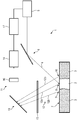
- the sole Fig. is a schematic diagram and shows an apparatus according to an embodiment of the present invention.
- the Fig. shows an apparatus 1 for additively manufacturing of three-dimensional objects 2 by means of successive layerwise selective irradiation and consolidation of layers of a build material 3 which can be consolidated by means of an energy beam 4, with an irradiation device 5 configured to generate the energy beam 4, wherein the energy beam 4 propagates along an optical beam path 6 of the energy beam 4 onto a build plane 7.
- the energy beam 4 irradiates build material 3 in multiple consolidation zones 8. Therefore, build material 3 in a consolidation zone 8 is irradiated by the energy beam 4 and thereby consolidated.
- the Fig. further shows adjacent zones 9, 10 adjacent to the consolidation zone 8, wherein the adjacent zones 9, 10 are in thermal contact with the consolidation zone 8 in that thermal energy deposited in the consolidation zone 8 also heats the adjacent zones 9, 10.
- the apparatus 1 comprises a detection device 11 that is configured to detect radiation 12a, 12b emitted from the adjacent zones 9, 10 and the consolidation zone 8 traveling an optical beam path 12 of the emitted radiation 12a, 12b.
- radiation 12a that is emitted from the consolidation zone 8 is indicated with the reference sign 12a
- radiation 12b emitted from one of the adjacent zones 9, 10 is indicated with reference sign 12b.
- the detection device 11 detects the entire radiation 12a, 12b that is emitted from the build plane 7 such as radiation 12b of the energy beam 4 that is reflected at the surface of the build plane 7 as well as thermal radiation 12a, 12b emitted due to heating of the build material 3 in the consolidation zone 8 and the adjacent zones 9, 10.
- the detection device 11 comprises a scanning unit 13 configured to guide radiation 12a, 12b emitted from the build plane 7 to a measuring unit 14 comprising an optical sensor, for example a CMOS or CCD sensor.
- the measuring unit 14 may be built as or comprise a pyrometer camera configured to provide suitable local resolution to detect the temperature of the single zones 8 to 10.
- Radiation 12a emitted from the consolidation zone 8 and radiation 12b emitted from the adjacent zones 9, 10 is transmitted through a protective glass 15 that is transparent in a wavelength spectrum e.g. of 400 nm to 2000 nm.
- a protective glass 15 that is transparent in a wavelength spectrum e.g. of 400 nm to 2000 nm.
- the scanning unit 13 guides the radiation 12a, 12b to the measuring unit 14, wherein the radiation 12a, 12b passes through an optical element 16 that is built as an apochromat.
- the detection device 11 is configured to detect radiation 12a, 12b and thereby detect the temperature of the consolidation zone 8 and the adjacent zones 9, 10. By detecting the temperature it is possible to determine a temperature gradient between the adjacent zone 9 and the consolidation zone 8 and between the consolidation zone 8 and the adjacent zone 10. Further, respective information can be generated dependent on the detected temperatures and the determined temperature gradients relating to properties of the object 2.
- the apparatus 1 further comprises a control unit 17 that is configured to control various process parameters, for example beam parameters such as a power and/or an intensity of the energy beam 4.
- the control unit 17 may control the irradiation device 5, for example the beam velocity of the energy beam 4, e.g. the velocity of the variation of the position of the energy beam 4 in the build plane 7 traveling along the energy beam path.
- an optical beam path 12 of the radiation 12a, 12b emitted from the build plane 7 differs from the optical beam path 6 of the energy beam 4.
- the irradiation device 5 does not have to be changed in terms of the transmission spectrum of single optical components (not shown) of the irradiation device 5.
- the detection device 11 can be used that allows for an analysis or a detection of the radiation 12a, 12b without or with reduced loss of information due to a wide transmittance spectrum of the protective glass 15 and the other components used in the detection device 11.
- the control unit 17 further is configured to control the temperature and the temperature gradient in or between the respective zones 8 to 10. In particular, if a defined threshold of the temperature gradient is exceeded, the control unit 17 may control the respective process parameter, in particular an energy beam power or an energy beam intensity of the energy beam 4 to avoid negative impacts on the object 2 such as mechanical stress or thermal strain that may lead to cracks in the object 2.
- the respective process parameter in particular an energy beam power or an energy beam intensity of the energy beam 4 to avoid negative impacts on the object 2 such as mechanical stress or thermal strain that may lead to cracks in the object 2.
- the apparatus 1 can comprise a heating element (not shown), e.g. a water heater located below the build plane 7 or a radiant heater, configured to heat the adjacent zones 9, 10 to reduce a temperature gradient between the adjacent zones 9, 10 and the consolidation zone 8 by heating the adjacent zones 9, 10.
- a heating element e.g. a water heater located below the build plane 7 or a radiant heater, configured to heat the adjacent zones 9, 10 to reduce a temperature gradient between the adjacent zones 9, 10 and the consolidation zone 8 by heating the adjacent zones 9, 10.
Landscapes
- Engineering & Computer Science (AREA)
- Chemical & Material Sciences (AREA)
- Materials Engineering (AREA)
- Manufacturing & Machinery (AREA)
- Physics & Mathematics (AREA)
- Optics & Photonics (AREA)
- Mechanical Engineering (AREA)
- Plasma & Fusion (AREA)
- Analytical Chemistry (AREA)
- Automation & Control Theory (AREA)
- Ceramic Engineering (AREA)
- Inorganic Chemistry (AREA)
- Structural Engineering (AREA)
- Organic Chemistry (AREA)
- Laser Beam Processing (AREA)
- Producing Shaped Articles From Materials (AREA)
- Powder Metallurgy (AREA)
- Heating, Cooling, Or Curing Plastics Or The Like In General (AREA)
Claims (12)
- Vorrichtung (1) zur additiven Herstellung von dreidimensionalen Objekten (2) durch aufeinanderfolgende schichtweise selektive Bestrahlung und Verfestigung von Schichten eines Aufbaumaterials (3), wobei die Vorrichtung umfasst:eine Bestrahlungsvorrichtung (5), die konfiguriert ist, einen Energiestrahl (4) zu erzeugen, um Schichten des Aufbaumaterials (3) in mindestens einer Verfestigungszone (8) zu bestrahlen und dadurch zu verfestigen, wobei die Bestrahlungsvorrichtung (5) mindestens eine Strahlablenkungseinheit umfasst, die konfiguriert ist, den Energiestrahl (4) entlang eines optischen Strahlengangs (6) des Energiestrahls (4) von der mindestens einen Strahlablenkungseinheit auf eine Aufbauebene (7) zu leiten; undeine Detektionsvorrichtung (11), die konfiguriert ist, Strahlung (l 2b) zu detektieren, die von mindestens einer an die Konsolidierungszone (8) angrenzenden Zone (9, 10) emittiert wird, oder Strahlung (12a) zu detektieren, die von der Konsolidierungszone (8) emittiert wird, und Strahlung (12b), die von der angrenzenden Zone (9, 10) emittiert wird;gekennzeichnet durch eine Abtasteinheit (13), die konfiguriert ist, die Strahlung (12a, 12b), die von der mindestens einen Konsolidierungszone (8) und/oder der mindestens einen Konsolidierungszone (9) emittiert wird, zu der Detektionsvorrichtung (11) abzulenken.mindestens einer benachbarten Zone (9, 10), wobei die Strahlung (12a, 12b) einen optischen Strahlengang (12) von der Bauebene zur Abtasteinheit (13) durchläuft, der sich von dem optischen Strahlengang (6) des Energiestrahls (4) von der mindestens einen Strahlablenkeinheit auf die Bauebene (7) unterscheidet.
- Vorrichtung nach Anspruch 1, dadurch gekennzeichnet, dass die Erfassungseinrichtung (11) ausgebildet ist, eine Temperatur mindestens einer Konsolidierungszone (8) und/oder mindestens einer benachbarten Zone (9, 10) zu erfassen und/oder einen Temperaturgradienten zwischen mindestens einer Konsolidierungszone (8) und mindestens einer benachbarten Zone (9, 10) zu ermitteln.
- Vorrichtung nach Anspruch 2, gekennzeichnet durch eine Steuereinheit (17), die konfiguriert ist, mindestens einen Prozessparameter in Abhängigkeit von der erfassten Temperatur und/oder dem ermittelten Temperaturgradienten anzupassen oder einzustellen.
- Vorrichtung nach Anspruch 3, dadurch gekennzeichnet, dass die Steuereinheit (17) ausgebildet ist, um in Abhängigkeit von der erfassten Temperatur und/oder dem ermittelten Temperaturgradienten, insbesondere bei Überschreiten eines vordefinierten Schwellenwertes, die Temperatur in mindestens einer Konsolidierungszone (8) zu steuern, insbesondere abzusenken, und/oder die Temperatur in mindestens einer benachbarten Zone (9, 10) zu steuern, insbesondere zu erhöhen, und/oder den Temperaturgradienten zwischen mindestens einer Konsolidierungszone (8) und mindestens einer benachbarten Zone (9, 10) zu verringern.
- Vorrichtung nach Anspruch 3 oder 4, dadurch gekennzeichnet, dass die Steuereinheit (17) so konfiguriert ist, dass sie die Temperatur und/oder den Temperaturgradienten in Abhängigkeit von einem Umgebungsparameter und/oder einer Bahngeschwindigkeit des Energiestrahls (4) und/oder einem Zustand des Aufbaumaterials (3) steuert.
- Vorrichtung nach einem der vorhergehenden Ansprüche, gekennzeichnet durch einen Datenspeicher, der zum Speichern mindestens eines Parameters, insbesondere einer Temperatur und/oder eines Temperaturgradienten, ausgebildet ist.
- Vorrichtung nach einem der vorhergehenden Ansprüche, dadurch gekennzeichnet, dass die Abtasteinheit (13) mit der Bestrahlungsvorrichtung(5), insbesondere mit mindestens einer Strahlumlenkeinheit der Bestrahlungsvorrichtung(5), die zum Führen des Energiestrahls (4) über die Aufbauebene (7) ausgebildet ist, synchronisiert ist, indem die mindestens eine Konsolidierungszone (8) und/oder die mindestens eine benachbarte Zone (9, 10) auf eine Messeinheit (14) der Detektionsvorrichtung (11) abgebildet wird.
- Vorrichtung nach Anspruch 7, dadurch gekennzeichnet, dass die Detektionsvorrichtung (11) mindestens ein optisches Element (16), insbesondere einen Apochromaten, umfasst, das zur Abbildung der mindestens einen Konsolidierungszone (8) und/oder der mindestens einen benachbarten Zone (9, 10) auf die Messeinheit ausgebildet ist.
- Vorrichtung nach Anspruch 7 oder 8, dadurch gekennzeichnet, dass die Messeinheit (14) mindestens eine Kamera, vorzugsweise eine Pyrometerkamera, insbesondere eine Quotientenpyrometerkamera, umfasst.
- Vorrichtung nach einem der vorhergehenden Ansprüche, gekennzeichnet durch ein Schutzglas(15), das zwischen der Bauebene (7) und der Detektionsvorrichtung (11) angeordnet ist, wobei das Transmissionsspektrum des Schutzglases (15) im Bereich von 170 nm bis 5000 nm, vorzugsweise von 400 nm bis 2000 nm, liegt.
- Verfahren zum Betreiben der Vorrichtung nach einem der vorhergehenden Ansprüche, zur additiven Herstellung von dreidimensionalen Objekten (2) mittels sukzessiver schichtweiser selektiver Bestrahlung und Verfestigung von Schichten eines mittels eines Energiestrahls (4) verfestigbaren Aufbaumaterials (3), wobei sich der Energiestrahl (4) entlang eines Energiestrahls (4) von mindestens einer Strahlablenkungseinheit auf eine Bauebene (7), wobei der Energiestrahl (4) Aufbaumaterial (3) in mindestens einer Konsolidierungszone (8) bestrahlt, dadurch gekennzeichnet, dass Strahlung (12b), die von mindestens einer an die Konsolidierungszone (8) benachbarten Zone (9, 10) emittiert wird, oder Strahlung (12a), die von der Konsolidierungszone (8) emittiert wird, und Strahlung (12b), die von der benachbarten Zone (9, 10) emittiert wird, einen optischen Strahlengang (12) von der Aufbauebene (7) zu einer Abtasteinheit (13) durchläuft, der optische Strahlengang (12) der Strahlung (12a, 12b) sich von dem optischen Strahlengang (6) des Energiestrahls (4) von der mindestens einen Strahlablenkungseinheit auf die Aufbauebene (7) unterscheidet, wobei die Abtasteinheit (13) die Strahlung (12a, 12b) zu einer Detektionsvorrichtung (11) ablenkt und die Detektionsvorrichtung (11) die Strahlung (12a, 12b) detektiert.
- Verfahren nach Anspruch 11, gekennzeichnet durch die folgenden Schritte:Erfassen von Strahlung (12) mit der Erfassungsvorrichtung (11), die von mindestens einer Konsolidierungszone (8), die direkt von dem Energiestrahl (4) bestrahlt wird, und mindestens einer benachbarten Zone (9, 10), die nicht direkt von dem Energiestrahl (4) bestrahlt wird, ausgesandt wird;Erfassen einer Temperatur der mindestens einen Konsolidierungszone (8) und/oder mindestens einer benachbarten Zone (9, 10) und/oder Bestimmen eines Temperaturgradienten zwischen mindestens einer Konsolidierungszone (8) und/oder mindestens einer benachbarten Zone (9, 10) mit der Erfassungseinrichtung (11); undSteuerung mindestens eines Prozessparameters in Abhängigkeit von der erfassten Temperatur und/oder dem ermittelten Temperaturgradienten.
Priority Applications (4)
| Application Number | Priority Date | Filing Date | Title |
|---|---|---|---|
| EP17187997.6A EP3446855B1 (de) | 2017-08-25 | 2017-08-25 | Vorrichtung zur generativen fertigung von dreidimensionalen objekten |
| CN201711136196.7A CN109421275B (zh) | 2017-08-25 | 2017-11-16 | 用于制造三维物体的设备 |
| JP2018019759A JP6708674B2 (ja) | 2017-08-25 | 2018-02-07 | 3次元の物体を製造する装置 |
| US16/002,448 US20190060999A1 (en) | 2017-08-25 | 2018-06-07 | Apparatus for additively manufacturing of three-dimensional objects |
Applications Claiming Priority (1)
| Application Number | Priority Date | Filing Date | Title |
|---|---|---|---|
| EP17187997.6A EP3446855B1 (de) | 2017-08-25 | 2017-08-25 | Vorrichtung zur generativen fertigung von dreidimensionalen objekten |
Publications (2)
| Publication Number | Publication Date |
|---|---|
| EP3446855A1 EP3446855A1 (de) | 2019-02-27 |
| EP3446855B1 true EP3446855B1 (de) | 2021-11-24 |
Family
ID=59702639
Family Applications (1)
| Application Number | Title | Priority Date | Filing Date |
|---|---|---|---|
| EP17187997.6A Active EP3446855B1 (de) | 2017-08-25 | 2017-08-25 | Vorrichtung zur generativen fertigung von dreidimensionalen objekten |
Country Status (4)
| Country | Link |
|---|---|
| US (1) | US20190060999A1 (de) |
| EP (1) | EP3446855B1 (de) |
| JP (1) | JP6708674B2 (de) |
| CN (1) | CN109421275B (de) |
Families Citing this family (3)
| Publication number | Priority date | Publication date | Assignee | Title |
|---|---|---|---|---|
| EP3431289A1 (de) * | 2017-07-21 | 2019-01-23 | CL Schutzrechtsverwaltungs GmbH | Vorrichtung zur generativen fertigung von dreidimensionalen objekten |
| CN108746615B (zh) * | 2018-06-15 | 2020-01-10 | 长沙理工大学 | 一种提高激光增材制造钛合金层间结合性能的方法 |
| US20210339477A1 (en) * | 2020-05-01 | 2021-11-04 | Formlabs, Inc. | Techniques for producing thermal support structures in additive fabrication and related systems and methods |
Family Cites Families (22)
| Publication number | Priority date | Publication date | Assignee | Title |
|---|---|---|---|---|
| JPS6216894A (ja) * | 1985-07-17 | 1987-01-26 | Toyota Motor Corp | アルミニウム系母材への肉盛方法 |
| JPH02225580A (ja) * | 1988-11-16 | 1990-09-07 | Ricoh Co Ltd | 等倍光センサーの保護ガラス板用接着剤 |
| US5427733A (en) * | 1993-10-20 | 1995-06-27 | United Technologies Corporation | Method for performing temperature-controlled laser sintering |
| US5393482A (en) * | 1993-10-20 | 1995-02-28 | United Technologies Corporation | Method for performing multiple beam laser sintering employing focussed and defocussed laser beams |
| JPH10211658A (ja) * | 1997-01-31 | 1998-08-11 | Toyota Motor Corp | 粉粒体積層造形方法及びその装置 |
| CN1087115C (zh) * | 1998-12-10 | 2002-07-03 | 山西大学 | 全固化单频倍频激光器 |
| JP3565186B2 (ja) * | 2001-06-26 | 2004-09-15 | 松下電工株式会社 | 光造形システムにおけるレーザビームの偏向制御方法及びその装置 |
| US6930278B1 (en) * | 2004-08-13 | 2005-08-16 | 3D Systems, Inc. | Continuous calibration of a non-contact thermal sensor for laser sintering |
| DE102005015870B3 (de) * | 2005-04-06 | 2006-10-26 | Eos Gmbh Electro Optical Systems | Vorrichtung und Verfahren zum Herstellen eines dreidimensionalen Objekts |
| US20100103798A1 (en) * | 2006-11-10 | 2010-04-29 | Gore Makarand P | Optical data recording and imaging on media using apochromatic lenses and a light separating means |
| DE102009016585A1 (de) * | 2009-04-06 | 2010-10-07 | Eos Gmbh Electro Optical Systems | Verfahren und Vorrichtung zum Kalibrieren einer Bestrahlungsvorrichtung |
| KR101596432B1 (ko) * | 2009-07-15 | 2016-02-22 | 아르켐 에이비 | 삼차원 물체의 제작 방법 및 장치 |
| DE202010010771U1 (de) * | 2010-07-28 | 2011-11-14 | Cl Schutzrechtsverwaltungs Gmbh | Laserschmelzvorrichtung zum Herstellen eines dreidimensionalen Bauteils |
| US10124410B2 (en) * | 2010-09-25 | 2018-11-13 | Ipg Photonics Corporation | Methods and systems for coherent imaging and feedback control for modification of materials |
| DE102012202487A1 (de) * | 2012-02-17 | 2013-08-22 | Evonik Industries Ag | Verfahren zum Aufschmelzen/Sintern von Pulverpartikeln zur schichtweisen Herstellung von dreidimensionalen Objekten |
| KR101230155B1 (ko) * | 2012-09-12 | 2013-02-13 | 주식회사 에이팸 | 디스플레이용 보호 글라스 및 그 제조방법 |
| DE102013017792A1 (de) * | 2013-10-28 | 2015-04-30 | Cl Schutzrechtsverwaltungs Gmbh | Verfahren zum Herstellen eines dreidimensionalen Bauteils |
| WO2015108560A1 (en) * | 2014-01-16 | 2015-07-23 | Hewlett-Packard Development Company, L.P. | Temperature determination based on emissivity |
| CN106061714B (zh) * | 2014-01-16 | 2019-07-12 | 惠普发展公司,有限责任合伙企业 | 基于辐射率的温度确定 |
| DE102015202964A1 (de) * | 2015-02-18 | 2016-08-18 | Eos Gmbh Electro Optical Systems | Vorrichtung und Verfahren zum Herstellen eines dreidimensionalen Objekts |
| CN104907562B (zh) * | 2015-06-05 | 2018-01-26 | 湖南华曙高科技有限责任公司 | 用于制造三维物体的设备 |
| JP6850945B2 (ja) * | 2016-02-19 | 2021-03-31 | 株式会社アスペクト | 粉末床溶融結合装置 |
-
2017
- 2017-08-25 EP EP17187997.6A patent/EP3446855B1/de active Active
- 2017-11-16 CN CN201711136196.7A patent/CN109421275B/zh active Active
-
2018
- 2018-02-07 JP JP2018019759A patent/JP6708674B2/ja active Active
- 2018-06-07 US US16/002,448 patent/US20190060999A1/en active Pending
Also Published As
| Publication number | Publication date |
|---|---|
| JP2019038245A (ja) | 2019-03-14 |
| CN109421275A (zh) | 2019-03-05 |
| JP6708674B2 (ja) | 2020-06-10 |
| CN109421275B (zh) | 2021-07-23 |
| EP3446855A1 (de) | 2019-02-27 |
| US20190060999A1 (en) | 2019-02-28 |
Similar Documents
| Publication | Publication Date | Title |
|---|---|---|
| CN110352104B (zh) | 用于基于构建材料的局部热导率来制造部件的系统及方法 | |
| EP3446855B1 (de) | Vorrichtung zur generativen fertigung von dreidimensionalen objekten | |
| EP3446854B1 (de) | Vorrichtung und verfahren zur generativen fertigung von dreidimensionalen objekten | |
| AU2006264193B2 (en) | Method and device for producing a 3D object by means of a generative 3D-method | |
| US20190054687A1 (en) | Apparatus for additively manufacturing three-dimensional objects | |
| EP3441214B1 (de) | Vorrichtung zur generativen fertigung von dreidimensionalen objekten | |
| JP2012011402A (ja) | ワークの加工方法、ワークの加工用光照射装置およびそれに用いるプログラム | |
| US11904545B2 (en) | Apparatus for additively manufacturing three-dimensional objects | |
| CN110435141B (zh) | 添加式地制造三维物体的装置 | |
| EP3536485B1 (de) | Vorrichtung zur generativen fertigung dreidimensionaler objekte | |
| JP6590960B2 (ja) | 3次元物体を製造するための装置 | |
| EP3572213B1 (de) | Vorrichtung zur generativen fertigung dreidimensionaler objekte und verfahren zum betrieb einer vorrichtung zu generativen fertigung | |
| JP2021066960A (ja) | 3次元の物体を付加製造する装置 | |
| EP3613561B1 (de) | Vorrichtung zur generativen fertigung dreidimensionaler objekte | |
| EP3736112B1 (de) | Verfahren zur bestimmung eines betriebsparameters für eine bildgebungsvorrichtung und generative herstelungsvorrichtung | |
| CN113939377B (zh) | 设备和方法 | |
| Bidare | An open-architecture laser powder bed fusion system and its use for in-situ process measurements |
Legal Events
| Date | Code | Title | Description |
|---|---|---|---|
| PUAI | Public reference made under article 153(3) epc to a published international application that has entered the european phase |
Free format text: ORIGINAL CODE: 0009012 |
|
| STAA | Information on the status of an ep patent application or granted ep patent |
Free format text: STATUS: THE APPLICATION HAS BEEN PUBLISHED |
|
| AK | Designated contracting states |
Kind code of ref document: A1 Designated state(s): AL AT BE BG CH CY CZ DE DK EE ES FI FR GB GR HR HU IE IS IT LI LT LU LV MC MK MT NL NO PL PT RO RS SE SI SK SM TR |
|
| AX | Request for extension of the european patent |
Extension state: BA ME |
|
| STAA | Information on the status of an ep patent application or granted ep patent |
Free format text: STATUS: REQUEST FOR EXAMINATION WAS MADE |
|
| 17P | Request for examination filed |
Effective date: 20190827 |
|
| RBV | Designated contracting states (corrected) |
Designated state(s): AL AT BE BG CH CY CZ DE DK EE ES FI FR GB GR HR HU IE IS IT LI LT LU LV MC MK MT NL NO PL PT RO RS SE SI SK SM TR |
|
| STAA | Information on the status of an ep patent application or granted ep patent |
Free format text: STATUS: EXAMINATION IS IN PROGRESS |
|
| 17Q | First examination report despatched |
Effective date: 20210224 |
|
| RIC1 | Information provided on ipc code assigned before grant |
Ipc: B29C 64/153 20170101AFI20210429BHEP Ipc: B29C 64/135 20170101ALI20210429BHEP Ipc: B29C 64/393 20170101ALI20210429BHEP Ipc: B22F 10/20 20210101ALI20210429BHEP Ipc: B22F 10/30 20210101ALI20210429BHEP Ipc: B33Y 30/00 20150101ALI20210429BHEP Ipc: B33Y 50/02 20150101ALI20210429BHEP |
|
| GRAP | Despatch of communication of intention to grant a patent |
Free format text: ORIGINAL CODE: EPIDOSNIGR1 |
|
| STAA | Information on the status of an ep patent application or granted ep patent |
Free format text: STATUS: GRANT OF PATENT IS INTENDED |
|
| INTG | Intention to grant announced |
Effective date: 20210607 |
|
| GRAS | Grant fee paid |
Free format text: ORIGINAL CODE: EPIDOSNIGR3 |
|
| GRAA | (expected) grant |
Free format text: ORIGINAL CODE: 0009210 |
|
| STAA | Information on the status of an ep patent application or granted ep patent |
Free format text: STATUS: THE PATENT HAS BEEN GRANTED |
|
| AK | Designated contracting states |
Kind code of ref document: B1 Designated state(s): AL AT BE BG CH CY CZ DE DK EE ES FI FR GB GR HR HU IE IS IT LI LT LU LV MC MK MT NL NO PL PT RO RS SE SI SK SM TR |
|
| REG | Reference to a national code |
Ref country code: GB Ref legal event code: FG4D |
|
| REG | Reference to a national code |
Ref country code: DE Ref legal event code: R096 Ref document number: 602017049698 Country of ref document: DE |
|
| REG | Reference to a national code |
Ref country code: AT Ref legal event code: REF Ref document number: 1449537 Country of ref document: AT Kind code of ref document: T Effective date: 20211215 |
|
| REG | Reference to a national code |
Ref country code: IE Ref legal event code: FG4D |
|
| REG | Reference to a national code |
Ref country code: LT Ref legal event code: MG9D |
|
| REG | Reference to a national code |
Ref country code: NL Ref legal event code: MP Effective date: 20211124 |
|
| REG | Reference to a national code |
Ref country code: AT Ref legal event code: MK05 Ref document number: 1449537 Country of ref document: AT Kind code of ref document: T Effective date: 20211124 |
|
| PG25 | Lapsed in a contracting state [announced via postgrant information from national office to epo] |
Ref country code: RS Free format text: LAPSE BECAUSE OF FAILURE TO SUBMIT A TRANSLATION OF THE DESCRIPTION OR TO PAY THE FEE WITHIN THE PRESCRIBED TIME-LIMIT Effective date: 20211124 Ref country code: LT Free format text: LAPSE BECAUSE OF FAILURE TO SUBMIT A TRANSLATION OF THE DESCRIPTION OR TO PAY THE FEE WITHIN THE PRESCRIBED TIME-LIMIT Effective date: 20211124 Ref country code: FI Free format text: LAPSE BECAUSE OF FAILURE TO SUBMIT A TRANSLATION OF THE DESCRIPTION OR TO PAY THE FEE WITHIN THE PRESCRIBED TIME-LIMIT Effective date: 20211124 Ref country code: BG Free format text: LAPSE BECAUSE OF FAILURE TO SUBMIT A TRANSLATION OF THE DESCRIPTION OR TO PAY THE FEE WITHIN THE PRESCRIBED TIME-LIMIT Effective date: 20220224 Ref country code: AT Free format text: LAPSE BECAUSE OF FAILURE TO SUBMIT A TRANSLATION OF THE DESCRIPTION OR TO PAY THE FEE WITHIN THE PRESCRIBED TIME-LIMIT Effective date: 20211124 |
|
| PG25 | Lapsed in a contracting state [announced via postgrant information from national office to epo] |
Ref country code: IS Free format text: LAPSE BECAUSE OF FAILURE TO SUBMIT A TRANSLATION OF THE DESCRIPTION OR TO PAY THE FEE WITHIN THE PRESCRIBED TIME-LIMIT Effective date: 20220324 Ref country code: SE Free format text: LAPSE BECAUSE OF FAILURE TO SUBMIT A TRANSLATION OF THE DESCRIPTION OR TO PAY THE FEE WITHIN THE PRESCRIBED TIME-LIMIT Effective date: 20211124 Ref country code: PT Free format text: LAPSE BECAUSE OF FAILURE TO SUBMIT A TRANSLATION OF THE DESCRIPTION OR TO PAY THE FEE WITHIN THE PRESCRIBED TIME-LIMIT Effective date: 20220324 Ref country code: PL Free format text: LAPSE BECAUSE OF FAILURE TO SUBMIT A TRANSLATION OF THE DESCRIPTION OR TO PAY THE FEE WITHIN THE PRESCRIBED TIME-LIMIT Effective date: 20211124 Ref country code: NO Free format text: LAPSE BECAUSE OF FAILURE TO SUBMIT A TRANSLATION OF THE DESCRIPTION OR TO PAY THE FEE WITHIN THE PRESCRIBED TIME-LIMIT Effective date: 20220224 Ref country code: NL Free format text: LAPSE BECAUSE OF FAILURE TO SUBMIT A TRANSLATION OF THE DESCRIPTION OR TO PAY THE FEE WITHIN THE PRESCRIBED TIME-LIMIT Effective date: 20211124 Ref country code: LV Free format text: LAPSE BECAUSE OF FAILURE TO SUBMIT A TRANSLATION OF THE DESCRIPTION OR TO PAY THE FEE WITHIN THE PRESCRIBED TIME-LIMIT Effective date: 20211124 Ref country code: HR Free format text: LAPSE BECAUSE OF FAILURE TO SUBMIT A TRANSLATION OF THE DESCRIPTION OR TO PAY THE FEE WITHIN THE PRESCRIBED TIME-LIMIT Effective date: 20211124 Ref country code: GR Free format text: LAPSE BECAUSE OF FAILURE TO SUBMIT A TRANSLATION OF THE DESCRIPTION OR TO PAY THE FEE WITHIN THE PRESCRIBED TIME-LIMIT Effective date: 20220225 Ref country code: ES Free format text: LAPSE BECAUSE OF FAILURE TO SUBMIT A TRANSLATION OF THE DESCRIPTION OR TO PAY THE FEE WITHIN THE PRESCRIBED TIME-LIMIT Effective date: 20211124 |
|
| PG25 | Lapsed in a contracting state [announced via postgrant information from national office to epo] |
Ref country code: SM Free format text: LAPSE BECAUSE OF FAILURE TO SUBMIT A TRANSLATION OF THE DESCRIPTION OR TO PAY THE FEE WITHIN THE PRESCRIBED TIME-LIMIT Effective date: 20211124 Ref country code: SK Free format text: LAPSE BECAUSE OF FAILURE TO SUBMIT A TRANSLATION OF THE DESCRIPTION OR TO PAY THE FEE WITHIN THE PRESCRIBED TIME-LIMIT Effective date: 20211124 Ref country code: RO Free format text: LAPSE BECAUSE OF FAILURE TO SUBMIT A TRANSLATION OF THE DESCRIPTION OR TO PAY THE FEE WITHIN THE PRESCRIBED TIME-LIMIT Effective date: 20211124 Ref country code: EE Free format text: LAPSE BECAUSE OF FAILURE TO SUBMIT A TRANSLATION OF THE DESCRIPTION OR TO PAY THE FEE WITHIN THE PRESCRIBED TIME-LIMIT Effective date: 20211124 Ref country code: DK Free format text: LAPSE BECAUSE OF FAILURE TO SUBMIT A TRANSLATION OF THE DESCRIPTION OR TO PAY THE FEE WITHIN THE PRESCRIBED TIME-LIMIT Effective date: 20211124 Ref country code: CZ Free format text: LAPSE BECAUSE OF FAILURE TO SUBMIT A TRANSLATION OF THE DESCRIPTION OR TO PAY THE FEE WITHIN THE PRESCRIBED TIME-LIMIT Effective date: 20211124 |
|
| REG | Reference to a national code |
Ref country code: DE Ref legal event code: R097 Ref document number: 602017049698 Country of ref document: DE |
|
| PLBE | No opposition filed within time limit |
Free format text: ORIGINAL CODE: 0009261 |
|
| STAA | Information on the status of an ep patent application or granted ep patent |
Free format text: STATUS: NO OPPOSITION FILED WITHIN TIME LIMIT |
|
| PG25 | Lapsed in a contracting state [announced via postgrant information from national office to epo] |
Ref country code: AL Free format text: LAPSE BECAUSE OF FAILURE TO SUBMIT A TRANSLATION OF THE DESCRIPTION OR TO PAY THE FEE WITHIN THE PRESCRIBED TIME-LIMIT Effective date: 20211124 |
|
| 26N | No opposition filed |
Effective date: 20220825 |
|
| PG25 | Lapsed in a contracting state [announced via postgrant information from national office to epo] |
Ref country code: SI Free format text: LAPSE BECAUSE OF FAILURE TO SUBMIT A TRANSLATION OF THE DESCRIPTION OR TO PAY THE FEE WITHIN THE PRESCRIBED TIME-LIMIT Effective date: 20211124 |
|
| REG | Reference to a national code |
Ref country code: DE Ref legal event code: R081 Ref document number: 602017049698 Country of ref document: DE Owner name: CONCEPT LASER GMBH, DE Free format text: FORMER OWNER: CL SCHUTZRECHTSVERWALTUNGS GMBH, 96215 LICHTENFELS, DE |
|
| PG25 | Lapsed in a contracting state [announced via postgrant information from national office to epo] |
Ref country code: MC Free format text: LAPSE BECAUSE OF FAILURE TO SUBMIT A TRANSLATION OF THE DESCRIPTION OR TO PAY THE FEE WITHIN THE PRESCRIBED TIME-LIMIT Effective date: 20211124 |
|
| REG | Reference to a national code |
Ref country code: CH Ref legal event code: PL |
|
| PG25 | Lapsed in a contracting state [announced via postgrant information from national office to epo] |
Ref country code: LU Free format text: LAPSE BECAUSE OF NON-PAYMENT OF DUE FEES Effective date: 20220825 Ref country code: LI Free format text: LAPSE BECAUSE OF NON-PAYMENT OF DUE FEES Effective date: 20220831 Ref country code: CH Free format text: LAPSE BECAUSE OF NON-PAYMENT OF DUE FEES Effective date: 20220831 |
|
| REG | Reference to a national code |
Ref country code: BE Ref legal event code: MM Effective date: 20220831 |
|
| REG | Reference to a national code |
Ref country code: GB Ref legal event code: 732E Free format text: REGISTERED BETWEEN 20230406 AND 20230412 |
|
| PG25 | Lapsed in a contracting state [announced via postgrant information from national office to epo] |
Ref country code: IT Free format text: LAPSE BECAUSE OF FAILURE TO SUBMIT A TRANSLATION OF THE DESCRIPTION OR TO PAY THE FEE WITHIN THE PRESCRIBED TIME-LIMIT Effective date: 20211124 |
|
| P01 | Opt-out of the competence of the unified patent court (upc) registered |
Effective date: 20230516 |
|
| P02 | Opt-out of the competence of the unified patent court (upc) changed |
Effective date: 20230530 |
|
| PG25 | Lapsed in a contracting state [announced via postgrant information from national office to epo] |
Ref country code: IE Free format text: LAPSE BECAUSE OF NON-PAYMENT OF DUE FEES Effective date: 20220825 |
|
| PG25 | Lapsed in a contracting state [announced via postgrant information from national office to epo] |
Ref country code: BE Free format text: LAPSE BECAUSE OF NON-PAYMENT OF DUE FEES Effective date: 20220831 |
|
| PGFP | Annual fee paid to national office [announced via postgrant information from national office to epo] |
Ref country code: GB Payment date: 20230720 Year of fee payment: 7 |
|
| PGFP | Annual fee paid to national office [announced via postgrant information from national office to epo] |
Ref country code: FR Payment date: 20230720 Year of fee payment: 7 Ref country code: DE Payment date: 20230720 Year of fee payment: 7 |
|
| PG25 | Lapsed in a contracting state [announced via postgrant information from national office to epo] |
Ref country code: HU Free format text: LAPSE BECAUSE OF FAILURE TO SUBMIT A TRANSLATION OF THE DESCRIPTION OR TO PAY THE FEE WITHIN THE PRESCRIBED TIME-LIMIT; INVALID AB INITIO Effective date: 20170825 |
|
| PG25 | Lapsed in a contracting state [announced via postgrant information from national office to epo] |
Ref country code: CY Free format text: LAPSE BECAUSE OF FAILURE TO SUBMIT A TRANSLATION OF THE DESCRIPTION OR TO PAY THE FEE WITHIN THE PRESCRIBED TIME-LIMIT Effective date: 20211124 |
|
| PG25 | Lapsed in a contracting state [announced via postgrant information from national office to epo] |
Ref country code: MK Free format text: LAPSE BECAUSE OF FAILURE TO SUBMIT A TRANSLATION OF THE DESCRIPTION OR TO PAY THE FEE WITHIN THE PRESCRIBED TIME-LIMIT Effective date: 20211124 |
|
| PG25 | Lapsed in a contracting state [announced via postgrant information from national office to epo] |
Ref country code: TR Free format text: LAPSE BECAUSE OF FAILURE TO SUBMIT A TRANSLATION OF THE DESCRIPTION OR TO PAY THE FEE WITHIN THE PRESCRIBED TIME-LIMIT Effective date: 20211124 |