EP3446372B1 - Steckverbinderteil mit einem gekühlten kontaktelement - Google Patents
Steckverbinderteil mit einem gekühlten kontaktelement Download PDFInfo
- Publication number
- EP3446372B1 EP3446372B1 EP17718071.8A EP17718071A EP3446372B1 EP 3446372 B1 EP3446372 B1 EP 3446372B1 EP 17718071 A EP17718071 A EP 17718071A EP 3446372 B1 EP3446372 B1 EP 3446372B1
- Authority
- EP
- European Patent Office
- Prior art keywords
- heat
- connector part
- heat sink
- contact element
- coolant
- Prior art date
- Legal status (The legal status is an assumption and is not a legal conclusion. Google has not performed a legal analysis and makes no representation as to the accuracy of the status listed.)
- Active
Links
Images


Classifications
-
- H—ELECTRICITY
- H01—ELECTRIC ELEMENTS
- H01R—ELECTRICALLY-CONDUCTIVE CONNECTIONS; STRUCTURAL ASSOCIATIONS OF A PLURALITY OF MUTUALLY-INSULATED ELECTRICAL CONNECTING ELEMENTS; COUPLING DEVICES; CURRENT COLLECTORS
- H01R13/00—Details of coupling devices of the kinds covered by groups H01R12/70 or H01R24/00 - H01R33/00
- H01R13/46—Bases; Cases
- H01R13/533—Bases, cases made for use in extreme conditions, e.g. high temperature, radiation, vibration, corrosive environment, pressure
-
- B—PERFORMING OPERATIONS; TRANSPORTING
- B60—VEHICLES IN GENERAL
- B60L—PROPULSION OF ELECTRICALLY-PROPELLED VEHICLES; SUPPLYING ELECTRIC POWER FOR AUXILIARY EQUIPMENT OF ELECTRICALLY-PROPELLED VEHICLES; ELECTRODYNAMIC BRAKE SYSTEMS FOR VEHICLES IN GENERAL; MAGNETIC SUSPENSION OR LEVITATION FOR VEHICLES; MONITORING OPERATING VARIABLES OF ELECTRICALLY-PROPELLED VEHICLES; ELECTRIC SAFETY DEVICES FOR ELECTRICALLY-PROPELLED VEHICLES
- B60L1/00—Supplying electric power to auxiliary equipment of vehicles
- B60L1/02—Supplying electric power to auxiliary equipment of vehicles to electric heating circuits
- B60L1/04—Supplying electric power to auxiliary equipment of vehicles to electric heating circuits fed by the power supply line
-
- B—PERFORMING OPERATIONS; TRANSPORTING
- B60—VEHICLES IN GENERAL
- B60L—PROPULSION OF ELECTRICALLY-PROPELLED VEHICLES; SUPPLYING ELECTRIC POWER FOR AUXILIARY EQUIPMENT OF ELECTRICALLY-PROPELLED VEHICLES; ELECTRODYNAMIC BRAKE SYSTEMS FOR VEHICLES IN GENERAL; MAGNETIC SUSPENSION OR LEVITATION FOR VEHICLES; MONITORING OPERATING VARIABLES OF ELECTRICALLY-PROPELLED VEHICLES; ELECTRIC SAFETY DEVICES FOR ELECTRICALLY-PROPELLED VEHICLES
- B60L53/00—Methods of charging batteries, specially adapted for electric vehicles; Charging stations or on-board charging equipment therefor; Exchange of energy storage elements in electric vehicles
- B60L53/10—Methods of charging batteries, specially adapted for electric vehicles; Charging stations or on-board charging equipment therefor; Exchange of energy storage elements in electric vehicles characterised by the energy transfer between the charging station and the vehicle
- B60L53/14—Conductive energy transfer
- B60L53/16—Connectors, e.g. plugs or sockets, specially adapted for charging electric vehicles
-
- B—PERFORMING OPERATIONS; TRANSPORTING
- B60—VEHICLES IN GENERAL
- B60L—PROPULSION OF ELECTRICALLY-PROPELLED VEHICLES; SUPPLYING ELECTRIC POWER FOR AUXILIARY EQUIPMENT OF ELECTRICALLY-PROPELLED VEHICLES; ELECTRODYNAMIC BRAKE SYSTEMS FOR VEHICLES IN GENERAL; MAGNETIC SUSPENSION OR LEVITATION FOR VEHICLES; MONITORING OPERATING VARIABLES OF ELECTRICALLY-PROPELLED VEHICLES; ELECTRIC SAFETY DEVICES FOR ELECTRICALLY-PROPELLED VEHICLES
- B60L53/00—Methods of charging batteries, specially adapted for electric vehicles; Charging stations or on-board charging equipment therefor; Exchange of energy storage elements in electric vehicles
- B60L53/10—Methods of charging batteries, specially adapted for electric vehicles; Charging stations or on-board charging equipment therefor; Exchange of energy storage elements in electric vehicles characterised by the energy transfer between the charging station and the vehicle
- B60L53/14—Conductive energy transfer
- B60L53/18—Cables specially adapted for charging electric vehicles
-
- B—PERFORMING OPERATIONS; TRANSPORTING
- B60—VEHICLES IN GENERAL
- B60L—PROPULSION OF ELECTRICALLY-PROPELLED VEHICLES; SUPPLYING ELECTRIC POWER FOR AUXILIARY EQUIPMENT OF ELECTRICALLY-PROPELLED VEHICLES; ELECTRODYNAMIC BRAKE SYSTEMS FOR VEHICLES IN GENERAL; MAGNETIC SUSPENSION OR LEVITATION FOR VEHICLES; MONITORING OPERATING VARIABLES OF ELECTRICALLY-PROPELLED VEHICLES; ELECTRIC SAFETY DEVICES FOR ELECTRICALLY-PROPELLED VEHICLES
- B60L53/00—Methods of charging batteries, specially adapted for electric vehicles; Charging stations or on-board charging equipment therefor; Exchange of energy storage elements in electric vehicles
- B60L53/30—Constructional details of charging stations
- B60L53/302—Cooling of charging equipment
-
- H—ELECTRICITY
- H01—ELECTRIC ELEMENTS
- H01B—CABLES; CONDUCTORS; INSULATORS; SELECTION OF MATERIALS FOR THEIR CONDUCTIVE, INSULATING OR DIELECTRIC PROPERTIES
- H01B7/00—Insulated conductors or cables characterised by their form
- H01B7/42—Insulated conductors or cables characterised by their form with arrangements for heat dissipation or conduction
- H01B7/421—Insulated conductors or cables characterised by their form with arrangements for heat dissipation or conduction for heat dissipation
- H01B7/423—Insulated conductors or cables characterised by their form with arrangements for heat dissipation or conduction for heat dissipation using a cooling fluid
-
- B—PERFORMING OPERATIONS; TRANSPORTING
- B60—VEHICLES IN GENERAL
- B60L—PROPULSION OF ELECTRICALLY-PROPELLED VEHICLES; SUPPLYING ELECTRIC POWER FOR AUXILIARY EQUIPMENT OF ELECTRICALLY-PROPELLED VEHICLES; ELECTRODYNAMIC BRAKE SYSTEMS FOR VEHICLES IN GENERAL; MAGNETIC SUSPENSION OR LEVITATION FOR VEHICLES; MONITORING OPERATING VARIABLES OF ELECTRICALLY-PROPELLED VEHICLES; ELECTRIC SAFETY DEVICES FOR ELECTRICALLY-PROPELLED VEHICLES
- B60L53/00—Methods of charging batteries, specially adapted for electric vehicles; Charging stations or on-board charging equipment therefor; Exchange of energy storage elements in electric vehicles
- B60L53/10—Methods of charging batteries, specially adapted for electric vehicles; Charging stations or on-board charging equipment therefor; Exchange of energy storage elements in electric vehicles characterised by the energy transfer between the charging station and the vehicle
- B60L53/11—DC charging controlled by the charging station, e.g. mode 4
-
- H—ELECTRICITY
- H01—ELECTRIC ELEMENTS
- H01R—ELECTRICALLY-CONDUCTIVE CONNECTIONS; STRUCTURAL ASSOCIATIONS OF A PLURALITY OF MUTUALLY-INSULATED ELECTRICAL CONNECTING ELEMENTS; COUPLING DEVICES; CURRENT COLLECTORS
- H01R9/00—Structural associations of a plurality of mutually-insulated electrical connecting elements, e.g. terminal strips or terminal blocks; Terminals or binding posts mounted upon a base or in a case; Bases therefor
- H01R9/11—End pieces for multiconductor cables supported by the cable and for facilitating connections to other conductive members, e.g. for liquid cooled welding cables
-
- Y—GENERAL TAGGING OF NEW TECHNOLOGICAL DEVELOPMENTS; GENERAL TAGGING OF CROSS-SECTIONAL TECHNOLOGIES SPANNING OVER SEVERAL SECTIONS OF THE IPC; TECHNICAL SUBJECTS COVERED BY FORMER USPC CROSS-REFERENCE ART COLLECTIONS [XRACs] AND DIGESTS
- Y02—TECHNOLOGIES OR APPLICATIONS FOR MITIGATION OR ADAPTATION AGAINST CLIMATE CHANGE
- Y02T—CLIMATE CHANGE MITIGATION TECHNOLOGIES RELATED TO TRANSPORTATION
- Y02T10/00—Road transport of goods or passengers
- Y02T10/60—Other road transportation technologies with climate change mitigation effect
- Y02T10/70—Energy storage systems for electromobility, e.g. batteries
-
- Y—GENERAL TAGGING OF NEW TECHNOLOGICAL DEVELOPMENTS; GENERAL TAGGING OF CROSS-SECTIONAL TECHNOLOGIES SPANNING OVER SEVERAL SECTIONS OF THE IPC; TECHNICAL SUBJECTS COVERED BY FORMER USPC CROSS-REFERENCE ART COLLECTIONS [XRACs] AND DIGESTS
- Y02—TECHNOLOGIES OR APPLICATIONS FOR MITIGATION OR ADAPTATION AGAINST CLIMATE CHANGE
- Y02T—CLIMATE CHANGE MITIGATION TECHNOLOGIES RELATED TO TRANSPORTATION
- Y02T10/00—Road transport of goods or passengers
- Y02T10/60—Other road transportation technologies with climate change mitigation effect
- Y02T10/7072—Electromobility specific charging systems or methods for batteries, ultracapacitors, supercapacitors or double-layer capacitors
-
- Y—GENERAL TAGGING OF NEW TECHNOLOGICAL DEVELOPMENTS; GENERAL TAGGING OF CROSS-SECTIONAL TECHNOLOGIES SPANNING OVER SEVERAL SECTIONS OF THE IPC; TECHNICAL SUBJECTS COVERED BY FORMER USPC CROSS-REFERENCE ART COLLECTIONS [XRACs] AND DIGESTS
- Y02—TECHNOLOGIES OR APPLICATIONS FOR MITIGATION OR ADAPTATION AGAINST CLIMATE CHANGE
- Y02T—CLIMATE CHANGE MITIGATION TECHNOLOGIES RELATED TO TRANSPORTATION
- Y02T90/00—Enabling technologies or technologies with a potential or indirect contribution to GHG emissions mitigation
- Y02T90/10—Technologies relating to charging of electric vehicles
- Y02T90/12—Electric charging stations
-
- Y—GENERAL TAGGING OF NEW TECHNOLOGICAL DEVELOPMENTS; GENERAL TAGGING OF CROSS-SECTIONAL TECHNOLOGIES SPANNING OVER SEVERAL SECTIONS OF THE IPC; TECHNICAL SUBJECTS COVERED BY FORMER USPC CROSS-REFERENCE ART COLLECTIONS [XRACs] AND DIGESTS
- Y02—TECHNOLOGIES OR APPLICATIONS FOR MITIGATION OR ADAPTATION AGAINST CLIMATE CHANGE
- Y02T—CLIMATE CHANGE MITIGATION TECHNOLOGIES RELATED TO TRANSPORTATION
- Y02T90/00—Enabling technologies or technologies with a potential or indirect contribution to GHG emissions mitigation
- Y02T90/10—Technologies relating to charging of electric vehicles
- Y02T90/14—Plug-in electric vehicles
Definitions
- the invention relates to a connector part for connection to a mating connector part according to the preamble of claim 1.
- Such a connector part comprises a housing which has a plug-in section for plugging connection with the mating connector part, at least one contact element arranged on the plug-in section for making electrical contact with an associated mating contact element of the mating connector part, a heat conduction connected to the at least one contact element and a heat sink arranged in the housing , which is in heat-conducting connection with the at least one contact element in order to dissipate heat from the at least one contact element via the heat conduction.
- Such a connector part which, for example, from the DE 10 2010 050 562 B3 is known, can be used in particular as a charging plug or as a charging socket for charging an electrically powered vehicle (also referred to as an electric vehicle).
- a cable is connected on the one hand to a charging station and on the other hand carries the connector part in the form of a charging plug, which can be plugged into an associated mating connector part in the form of a charging socket on a vehicle in order to establish an electrical connection between the charging station and the Vehicle manufacture.
- Charging currents can basically be transmitted as direct currents or as alternating currents, whereby in particular charging currents in the form of direct current have a high current strength, for example greater than 200 A or even greater than 300 A or even 350 A, and cause the cable to heat up just like one with the Cable connected connector part can lead.
- the known charging cable has a cooling line which comprises a supply line and a return line for a coolant and thus enables a coolant flow to and from the charging cable.
- the cooling line of the DE 10 2010 007 975 B4 serves, on the one hand, to dissipate the heat loss that occurs in an energy store in a vehicle, but also to cool the cable itself.
- a charging system for charging an electric vehicle heat is not only generated on the cable with which a charging plug is connected to a charging station, for example, but also on the charging plug and in particular within the charging plug, for example on contact elements, via which electrical contact is established with associated mating contact elements, for example on the side of a charging socket on an electric vehicle, when the charging plug is plugged into the charging socket.
- Such contact elements which are made of an electrically conductive metal material, for example a copper material, heat up when a charging current flows through the contact elements, whereby the contact elements are basically to be dimensioned depending on the charging current to be transmitted so that the contact elements have a sufficient Have current carrying capacity and heating at the contact elements is limited.
- the rule here is that a contact element must be dimensioned larger, the larger the charging current to be transmitted.
- charging currents are transmitted by means of a transformer via a core arranged in a connector part.
- a heat conduction for dissipating heat can be extended in the core.
- the object of the present invention is to provide a plug connector part with a contact element which can have a high current carrying capacity, for example for use in a charging system for charging an electric vehicle.
- the connector part is characterized in that the first end of the heat conduction is plugged into an opening of a metallic connector and is connected to the associated contact element via the connector.
- a cooling body for cooling in the connector part, which can be designed as a charging plug or as a charging socket in the context of a charging system for charging an electric vehicle, which is connected to an associated contact element via heat conduction and which dissipates heat from the associated contact element can be.
- the contact element thus serves as a heat source
- the heat sink serves as a heat sink. Because the heat sink is connected to the associated contact element via the heat pipe, the heat sink can be spatially separated from the associated contact element within the housing of the connector part and can thus be placed at such a location within the housing , where installation space is available.
- the connector part can have a plurality of contact elements arranged on the plug-in section. If, for example, a direct current is to be transmitted, two contact elements can be provided which protrude into the plug-in section and which can each be brought into engagement with an associated mating contact element of an associated mating connector part.
- Each contact element is assigned a heat sink, which is connected to the assigned contact element via a (separate) heat line, so that the heat generated at the different contact elements can be dissipated via separate heat lines and heat sinks connected to the heat lines. This is particularly advantageous when the heat lines and the heat sinks are made of a metal material with good thermal conductivity in order to ensure electrical insulation between the contact elements and not impair it by the provision of the heat sinks.
- the contact elements are not connected to one another in an electrically conductive manner, so that no electrical contact is made between different contact elements, even if the heat lines and the heat sinks are made of an electrically conductive metal material.
- the heat conduction can, for example, have the shape of a solid, metal wire or rod which extends between a contact element and the associated heat sink.
- the heat conduction can also be designed as a so-called heat pipe, which can be used in the form of the heat pipe or the two-phase thermosiphon.
- Such a heat pipe can have a very low thermal resistance and thus a high thermal conductivity.
- a heat pipe can, for example, contain a hermetically encapsulated volume and is preferably of tubular design.
- the volume of the heat pipe is filled with a working medium, for example water or ammonia, which fills the volume in a partly liquid and partly vapor state.
- a working medium for example water or ammonia
- the functional principle of such a heat pipe is as follows: When heat is introduced, the working medium begins to evaporate. As a result, the pressure in the vapor space is increased locally above the liquid level, which leads to a low pressure gradient within the heat pipe. The resulting steam therefore flows to a point with a lower temperature and condenses there, so that at this point the temperature increases due to the heat of condensation released and the previously absorbed latent heat is released into the environment.
- thermosiphon thermosiphon
- capillary forces heat pipe
- the heat conduction assigned to a contact element is advantageously connected at a first end to the contact element in such a way that heat can be advantageously dissipated from the contact element via the heat conduction.
- the heat conduction can be firmly, for example cohesively, connected to the contact element.
- An (additional) connection piece is provided that is made of a material with good thermal conductivity, for example a metal material, and is connected to the contact element. The heat conduction is inserted into an opening in the connection piece and, if necessary, additionally welded, so that the heat conduction is connected to the contact element via the connection piece.
- the heat conduction can be plugged into an opening in the cooling body, for example.
- the heat conduction is thus positively connected to the heat sink in such a way that heat can be introduced into the heat sink via the heat conduction.
- the heat sink is, for example, made of a solid metal material and is thus designed as a solid body and has a comparatively large heat capacity.
- the opening of the cooling body can be designed, for example, as a blind hole into which the heat conduction is inserted. Due to the plugged connection with the heat sink, the heat conduction is held firmly on the heat sink, and the heat conduction can also be welded to the heat sink.
- the cooling body can have a fluid channel which extends long through the cooling body and can be flowed through by a coolant, so that heat can be absorbed and transported away by the cooling body.
- a first coolant line for supplying a coolant and a second coolant line for discharging the coolant after flowing through the cooling body can be connected to the cooling body, so that a coolant flow is provided via which heat can be transported away from the cooling body.
- a heat sink can also have two or even more fluid channels through which a coolant can flow.
- the fluid channels can, for example, extend parallel to one another through the (massive) heat sink, so that coolant can be conducted along different paths through the heat sink in order to absorb heat on the heat sink in this way.
- two fluid channels of the cooling body are flow-connected to one another via a deflection line. This enables a coolant to be introduced into a first fluid channel, so that the coolant flows along the first fluid channel, is directed to the second fluid channel via the deflection line and flows back through the heat sink via the second fluid channel.
- the fluid channels are thus in series connected to each other and allow a flow through the heat sink in the back and forth direction.
- heat sinks which are assigned to different contact elements, it is conceivable and possible to conduct a coolant in series or in parallel through the heat sinks.
- fluid channels of the heat sinks can be flow-connected to one another in series or in parallel, so that a coolant can be conducted to the heat sinks via a coolant line and can be diverted from the heat sinks via a second coolant line.
- fluid channels of different heat sinks are flow-connected to one another in series.
- a fluid channel of a first cooling body assigned to a first contact element can be connected via a deflection line to a fluid channel of a second cooling body assigned to a second contact element.
- This makes it possible, for example, to introduce a coolant into the fluid channel of the first cooling body, so that the fluid flows along the fluid channel of the first cooling body, is directed via the deflection line to the fluid channel of the second cooling body and then flows through the fluid channel of the second cooling body.
- the fluid channels of the heat sinks are thus interconnected to form a serial coolant circuit.
- two coolant lines can be routed, which serve to supply and discharge a coolant and thus provide a coolant circuit on the connector part.
- a first coolant line for supplying a coolant can be connected, for example, to a first heat sink
- a second coolant line for discharging the coolant is connected, for example, to a second heat sink
- fluid channels of the first heat sink and the second heat sink are flow-connected to one another in series, so that a supplied coolant is conducted via one or more fluid channels of the first heat sink to one or more fluid channels of the second heat sink and is finally discharged via the second coolant line.
- the heat sinks can in one embodiment be connected to one another and held in position to one another via a connection element made of a non-electrically conductive material, for example plastic.
- the heat sinks are advantageously kept at a distance from one another via the connecting element in such a way that the heat sinks do not touch one another and are therefore in particular not in electrical contact with one another. If the heat sinks are made of an electrically conductive metal material, this ensures that the electrical insulation of the individual contact elements of the connector part is not impaired from one another. In addition, a direct heat transfer from one heat sink to another heat sink can be avoided in this way.
- Fig. 1 shows a charging station 1, which is used to charge an electrically powered vehicle 4, also referred to as an electric vehicle.
- the charging station 1 is designed to provide a charging current in the form of an alternating current or a direct current and has a cable 2, which with one end 201 with the Charging station 1 and is connected at another end 200 to a connector part 3 in the form of a charging plug.
- the connector part 3 has plug-in sections 300, 301 on a housing 30, with which the connector part 3 can be brought into engagement with an associated mating connector part 40 in the form of a charging socket on the vehicle 4 while being plugged in.
- the charging station 1 can be electrically connected to the vehicle 4 in order to transmit charging currents from the charging station 1 to the vehicle 4.
- the transferred charging currents have a high current intensity, e.g. greater than 200 A, possibly even in the order of magnitude of 350 A or more. Due to such high charging currents, thermal losses occur on the cable 2 and also on the connector part 3 and the charging socket 40, which can lead to heating of the cable 2, the connector part 3 and the charging socket 40.
- the plug connector part 3 has a plurality of contact elements on its plug-in sections 300, 301.
- two contact elements for transmitting a charging current in the form of a direct current can be arranged on the plug-in section 301, while for example five contact elements are provided on the plug-in section 300 to provide five load contacts in order to transmit a (e.g. multi-phase) alternating current.
- a plug connector part are arranged on a lower plug section 301 within two plug pins 302 contact elements 31A, 31B, which are used to transmit a charging current in the form of a direct current.
- contact elements 32 are arranged in plug-in pins 303, which serve to transmit an alternating current.
- the plug connector part 3 is thus designed as a so-called combination plug, which can optionally be used to transmit direct currents or alternating currents.
- the contact elements 31A, 31B on the plug-in section 301 of the plug connector part 3 can be in an insertion direction E with mating contact elements 400 in the form of contact pins on the charging socket 40 side be brought into plugging engagement in order to electrically contact the contact elements 31A, 31B with the mating contact elements 400.
- Load lines 20, 21, which are used to transmit a load current to the connector part 3, are routed in the cable 2.
- a load line 20 is connected to each contact element 31A, 31B.
- Another load line 21 is used to energize the contact elements 33 on the other, upper plug-in section 300.
- heat sinks 35A, 35B are provided, which are connected to the contact elements 31A, 31B via heat lines 34A, 34B. Via the heat lines 34A, 34B, heat can be absorbed at the contact elements 31A, 31B and conducted to the heat sinks 35A, 35B in order in this way to dissipate heat from the contact elements 31A, 31B.
- a heat sink 35A, 35B is assigned to each contact element 31A, 31B.
- Each contact element 31A, 31B has a socket section 310 formed by resilient lamellae, to which a shaft 311 is connected.
- a connection piece 33A, 33B is arranged on this shaft 311, in that the cylindrical shaft 311 reaches through an opening 330 on the connection piece 33A, 33B.
- the heat conduction 34A, 34B assigned to the respective contact element 31A, 31B is inserted with one end 340 into an opening 331 of the connection piece 33A, 33B and extends from the contact element 31A, 31B to the assigned heat sink 35A, 35B, into which the heat conduction 34A , 34B is inserted with an end 341 remote from the end 340.
- the contact element 31A, 31B is made of a metal, for example a copper material.
- the connection piece 33A, 33B, the heat conduction 34A, 34B and the heat sink 35A, 35B are advantageously also made of a metal, in particular a metal that has good thermal conductivity.
- the connection piece 33A, 33B, the heat pipe 34A, 34B and the heat sink 35A, 35B are designed as solid, metal parts, so that the heat sink 35A, 35B in particular has a comparatively large heat capacity.
- a separate heat sink 35A, 35B is assigned to each contact element 31A, 31B.
- the individual heat sinks 35A, 35B are held in position relative to one another by a connecting element 350 made of an electrically insulating material, for example plastic, in such a way that the heat sinks 35A, 35B do not touch one another.
- the fact that the heat sinks 35A, 35B of the individual contact elements 31A, 31B are thus spatially separated from one another ensures that the electrical insulation between the contact elements 31A, 31B is not impaired by the heat sinks 35A, 35B connected to the contact elements 31A, 31B.
- the ends 341 of the heat pipes 34A, 34B are inserted into openings 351 in the form of blind holes on the heat sinks 35A, 35B and in this way firmly connected to the associated heat sinks 35A, 35B.
- the connection here is such that heat can be transferred from the heat lines 34A, 34B to the heat sinks 35A, 35B in a favorable manner.
- the connecting pieces 33A, 33B are firmly, for example, positively, non-positively (by pressing) or materially (e.g. by welding), connected to the shaft 311 of the respectively assigned contact element 31A, 31B.
- the heat lines 34A, 34B can be firmly connected, e.g., materially (e.g. by welding), on the one hand to the assigned connection piece 33A, 33B and on the other hand to the assigned heat sink 35A, 35B.
- the heat sinks 35A, 35B which are as shown in FIG Fig. 4 are shown arranged within the housing 30, actively cooled.
- the heat sinks 35A, 35B in particular, have Fig. 7 and 8th can be seen, two longitudinally extending, parallel fluid channels 352, 353 through which a (gaseous or liquid) coolant can flow in order to absorb heat on the heat sinks 35A, 35B and dissipate it from the heat sinks 35A, 35B.
- the fluid channels 352, 353 of the different heat sinks 35A, 35B can be connected to one another in series or in parallel in order to provide a coolant circuit for cooling. It is also conceivable and possible to connect each heat sink 35A, 35B to its own coolant circuit.
- coolant lines 38, 39 can be connected to the heat sinks 35A, 35B so that a coolant can be fed in a flow direction F1 via a coolant line 38 and can be discharged again via another coolant line 39 in a flow direction F2.
- the fluid channels 352, 353 of the coolant bodies 35A, 35B are flow-connected to one another in series, so that a supplied coolant flows through the fluid channels 352, 353 of the cooling bodies 35A, 35B in series.
- the fluid channels 352, 353 of each cooling body 35A, 35B are flow-connected to one another via a deflection line 36A, 36B, so that a coolant introduced into a fluid channel 353 is deflected via the deflection line 36A, 36B and flows back through the other fluid channel 352.
- the fluid channels 352, 353 are arranged on both sides of the opening 351 into which the associated heat line 34A, 24B is inserted, so that heat can be absorbed and dissipated on both sides of the heat line 34A, 34B via the fluid channels 352, 353.
- the fluid channel 352 of one heat sink 35A and the fluid channel 352 of the other heat sink 35B are flow-connected to one another via a deflection line 37, so that a coolant can flow from the fluid channel 352 of one heat sink 35A via the deflection line 37 into the fluid channel 352 of the other heat sink 35B.
- a first coolant line 38 is connected to the fluid channel 353 of the one cooling body 35A and is used, for example, to supply a coolant.
- Another, second coolant line 39 is connected to the cooling body 353 of the other cooling body 35B and serves to divert the coolant.
- a coolant can thus be supplied via the coolant line 38 and flow into the fluid channel 353 of the cooling body 35A.
- the coolant is conducted via the deflection line 36A into the fluid channel 352 of the heat sink 35A and from there via the bypass 37 into the fluid channel 352 of the heat sink 35B, flows via the fluid channel 352 of the heat sink 35B and the deflection line 36B in the flow direction F (see FIG Fig.
- the coolant lines 38, 39 are laid in the cable 2 and framed by a cable hose of the cable 2.
- the coolant line 38, 39 are guided in this way to the charging station 1 and are on the side of the charging station 1, for example with a Coolant pump connected to cause a coolant flow through the coolant lines 38, 39.
- all contact elements of the connector part can be cooled in the manner described. However, it is also conceivable and possible for only individual contact elements to be cooled.
- the connector part can have one or more heat sinks, in particular also more than two heat sinks. In this case, cooling can take place not only on contact elements provided for transmitting a direct current, but also on contact elements that are used to transmit an alternating current.
Landscapes
- Engineering & Computer Science (AREA)
- Power Engineering (AREA)
- Transportation (AREA)
- Mechanical Engineering (AREA)
- Electric Propulsion And Braking For Vehicles (AREA)
- Cooling Or The Like Of Electrical Apparatus (AREA)
- Connector Housings Or Holding Contact Members (AREA)
Description
- Die Erfindung betrifft ein Steckverbinderteil zum Verbinden mit einem Gegensteckverbinderteil nach dem Oberbegriff des Anspruchs 1.
- Ein solches Steckverbinderteil umfasst ein Gehäuse, das einen Steckabschnitt zum steckenden Verbinden mit dem Gegensteckverbinderteil aufweist, zumindest ein an dem Steckabschnitt angeordnetes Kontaktelement zum elektrischen Kontaktieren mit einem zugeordneten Gegenkontaktelement des Gegensteckverbinderteils, eine an das zumindest eine Kontaktelement angeschlossene Wärmeleitung und einen in dem Gehäuse angeordneten Kühlkörper, der zum Abführen von Wärme von dem zumindest einen Kontaktelement über die Wärmeleitung mit dem zumindest einen Kontaktelement in Wärmeleitverbindung steht.
- Ein solches Steckverbinderteil, welches beispielsweise aus der
DE 10 2010 050 562 B3 bekannt ist, kann insbesondere als Ladestecker oder als Ladebuchse zum Aufladen eines elektrisch angetriebenen Fahrzeugs (auch bezeichnet als Elektrofahrzeug) Verwendung finden. In diesem Fall ist beispielsweise ein Kabel einerseits an eine Ladestation angeschlossen und trägt andererseits das Steckverbinderteil in Form eines Ladesteckers, der in ein zugeordnetes Gegensteckverbinderteil in Form einer Ladebuchse an einem Fahrzeug eingesteckt werden kann, um auf diese Weise eine elektrische Verbindung zwischen der Ladestation und dem Fahrzeug herzustellen. - Ladeströme können grundsätzlich als Gleichströme oder als Wechselströme übertragen werden, wobei insbesondere Ladeströme in Form von Gleichstrom eine große Stromstärke, beispielsweise größer als 200 A oder sogar größer als 300 A oder gar 350 A, aufweisen und zu einer Erwärmung des Kabels genauso wie eines mit dem Kabel verbundenen Steckverbinderteils führen können.
- Ein aus der
DE 10 2010 007 975 B4 bekanntes Ladekabel weist eine Kühlleitung auf, die eine Zuleitung und eine Rückleitung für ein Kühlmittel umfasst und somit einen Kühlmittelfluss hin und zurück in dem Ladekabel ermöglicht. Die Kühlleitung derDE 10 2010 007 975 B4 dient zum einen zum Abführen von an einem Energiespeicher eines Fahrzeugs entstehender Verlustwärme, zudem aber auch zum Kühlen des Kabels an sich. - Bei einem Ladesystem zum Aufladen eines Elektrofahrzeugs entsteht Wärme nicht nur an dem Kabel, mit dem ein Ladestecker beispielsweise mit einer Ladestation verbunden ist, sondern auch an dem Ladestecker und insbesondere innerhalb des Ladesteckers beispielsweise an Kontaktelementen, über die ein elektrischer Kontakt mit zugeordneten Gegenkontaktelementen beispielsweise auf Seiten einer Ladebuchse an einem Elektrofahrzeug hergestellt wird, wenn der Ladestecker in die Ladebuchse eingesteckt ist. Solche Kontaktelemente, die aus einem elektrisch leitfähigen Metallmaterial, beispielsweise aus einem Kupferwerkstoff, gefertigt sind, erwärmen sich, wenn ein Ladestrom über die Kontaktelemente fließt, wobei grundsätzlich die Kontaktelemente in Abhängigkeit von dem zu übertragenden Ladestroms so zu dimensionieren sind, dass die Kontaktelemente eine hinreichende Stromtragfähigkeit aufweisen und eine Erwärmung an den Kontaktelementen begrenzt ist. Hierbei gilt, dass ein Kontaktelement umso größer zu dimensionieren ist, je größer der zu übertragende Ladestrom ist.
- Einer Skalierung der Kontaktelementgröße mit steigendem Ladestrom sind jedoch aufgrund des damit einhergehenden Bauraumbedarfs, des Gewichts und der Kosten Grenzen gesetzt. Es besteht daher ein Bedürfnis danach, einen großen Ladestrom mit einem vergleichsweise klein dimensionierten Kontaktelement zu übertragen.
- Bei einem aus der
WO 2015/119791 A1 bekannten Ladesystem zum Aufladen eines Elektrofahrzeugs sind innerhalb eines Ladekabels Kühlmittelleitungen geführt, über die Wärme auch aus dem Bereich eines an das Ladekabel angeschlossenen Steckverbinderteils abgeführt werden kann. - Bei einem aus der
US 5,909,099 bekannten Ladesystem werden Ladeströme transformatorisch über einen in einem Steckverbinderteil angeordneten Kern übertragen. In dem Kern kann eine Wärmeleitung zum Abführen von Wärme erstreckt sein. - Aufgabe der vorliegenden Erfindung ist es, ein Steckverbinderteil mit einem Kontaktelement zur Verfügung zu stellen, das eine große Stromtragfähigkeit beispielsweise zur Verwendung in einem Ladesystem zum Aufladen eines Elektrofahrzeugs aufweisen kann.
- Diese Aufgabe wird durch einen Gegenstand mit den Merkmalen des Anspruchs 1 gelöst.
- Das Steckverbinderteil zeichnet sich dadurch aus, dass die Wärmeleitung mit einem ersten Ende in eine Öffnung eines metallischen Anschlussstücks eingesteckt und über das Anschlussstück mit dem zugeordneten Kontaktelement verbunden ist.
- Demnach wird zur Kühlung in dem Steckverbinderteil, das beispielsweise als Ladestecker oder als Ladebuchse im Rahmen eines Ladesystems zum Aufladen eines Elektrofahrzeugs ausgebildet sein kann, ein Kühlkörper vorgesehen, der über eine Wärmeleitung mit einem zugeordneten Kontaktelement verbunden ist und über den Wärme von dem zugeordneten Kontaktelement abgeleitet werden kann. Das Kontaktelement dient somit als Wärmequelle, der Kühlkörper demgegenüber als Wärmesenke. Dadurch, dass der Kühlkörper über die Wärmeleitung (englisch "heat pipe") mit dem zugeordneten Kontaktelement verbunden ist, kann der Kühlkörper räumlich getrennt von dem zugeordneten Kontaktelement innerhalb des Gehäuses des Steckverbinderteils angeordnet werden und kann somit an einem solchen Ort innerhalb des Gehäuses platziert werden, an dem Bauraum zur Verfügung steht.
- Beispielsweise kann das Steckverbinderteil eine Mehrzahl von an dem Steckabschnitt angeordneten Kontaktelementen aufweisen. Soll beispielsweise ein Gleichstrom übertragen werden, können zwei Kontaktelemente vorgesehen sein, die in den Steckabschnitt hineinragen und die jeweils mit einem zugeordneten Gegenkontaktelement eines zugeordneten Gegensteckverbinderteils in Eingriff gebracht werden können. Jedem Kontaktelement ist ein Kühlkörper zugeordnet, der über eine (separate) Wärmeleitung mit dem zugeordneten Kontaktelement verbunden ist, sodass die an den unterschiedlichen Kontaktelementen entstehende Wärme über gesonderte Wärmeleitungen und mit den Wärmeleitungen verbundene Kühlkörper abgeleitet werden kann. Dies ist insbesondere dann vorteilhaft, wenn die Wärmeleitungen und die Kühlkörper aus einem gut wärmeleitfähigen Metallmaterial gefertigt sind, um eine elektrische Isolierung zwischen den Kontaktelementen zu gewährleisten und nicht durch das Vorsehen der Kühlkörper zu beeinträchtigen. Dadurch, dass separate Wärmeleitungen und Kühlkörper für die einzelnen Kontaktelemente vorgesehen sind, sind die Kontaktelemente nicht elektrisch leitend miteinander verbunden, sodass kein elektrischer Kontakt zwischen unterschiedlichen Kontaktelementen hergestellt wird, auch wenn die Wärmeleitungen und die Kühlkörper aus einem elektrisch leitfähigen Metallmaterial gefertigt sind.
- Die Wärmeleitung kann beispielsweise die Gestalt eines massiven, metallenen Drahts oder Stabs aufweisen, der sich zwischen einem Kontaktelement und dem zugeordneten Kühlkörper erstreckt. In einer besonders bevorzugten Ausgestaltung kann die Wärmeleitung auch als sogenanntes Wärmerohr ausgebildet sein, das in der Bauform der Heatpipe oder des Zwei-Phasen-Thermosiphons verwendet werden kann. Ein solches Wärmerohr kann einen sehr geringen Wärmewiderstand und somit eine hohe Wärmeleitfähigkeit aufweisen.
- Ein Wärmerohr kann beispielsweise ein hermetisch gekapseltes Volumen enthalten und ist vorzugsweise rohrförmig ausgestaltet. Das Volumen des Wärmerohrs ist mit einem Arbeitsmedium, zum Beispiel Wasser oder Ammoniak, gefüllt, welches das Volumen in teilweise flüssigem und teilweise dampfförmigem Zustand ausfüllt. Das Funktionsprinzip eines solchen Wärmerohrs ist dabei wie folgt: Bei Wärmeeintrag beginnt das Arbeitsmedium zu verdampfen. Dadurch wird über dem Flüssigkeitsspiegel der Druck im Dampfraum lokal erhöht, was zu einem geringen Druckgefälle innerhalb des Wärmerohrs führt. Der entstandene Dampf strömt deswegen zu einer Stelle mit niedrigerer Temperatur und kondensiert dort, sodass sich an dieser Stelle die Temperatur durch die freiwerdende Kondensationswärme erhöht und die zuvor aufgenommene latente Wärme an die Umgebung abgegeben wird. Das nun flüssige Arbeitsmedium kehrt durch Schwerkraft (Thermosiphon) bzw. durch Kapillarkräfte (Heatpipe) wieder zurück zu der Stelle, an der die Wärme eingeleitet worden ist. Während bei Wärmerohren nach der Bauform von Zwei-Phasen-Thermosiphons das Medium aufgrund von Schwerkraft kreist, fließt das Wärmeträgermedium bei Heatpipes nach dem Dochtprinzip (durch Wirkung von Kapillarkräften), sodass Heatpipes lageunabhängig sind.
- Die einem Kontaktelement zugeordnete Wärmeleitung ist vorteilhafterweise mit einem ersten Ende mit dem Kontaktelement derart verbunden, dass Wärme in günstiger Weise über die Wärmeleitung von dem Kontaktelement abgeleitet werden kann. Die Wärmeleitung kann fest, beispielsweise stoffschlüssig, mit dem Kontaktelement verbunden sein. Es ist ein (zusätzliches) Anschlussstück vorgesehen, dass aus einem gut wärmeleitfähigen Material, beispielsweise einem Metallmaterial gefertigt und mit dem Kontaktelement verbunden ist. Die Wärmeleitung ist in eine Öffnung des Anschlussstücks eingesteckt und gegebenenfalls zusätzlich verschweißt, sodass die Wärmeleitung über das Anschlussstück an das Kontaktelement angeschlossen ist.
- Mit einem dem ersten Ende abgewandten, zweiten Ende kann die Wärmeleitung demgegenüber beispielsweise in eine Öffnung des Kühlkörpers eingesteckt sein. Die Wärmeleitung ist somit formschlüssig mit dem Kühlkörper verbunden derart, dass Wärme über die Wärmeleitung in den Kühlkörper eingeleitet werden kann.
- Der Kühlkörper ist beispielsweise aus einem massiven Metallmaterial und somit als massiver Körper ausgestaltet und weist eine vergleichsweise große Wärmekapazität auf. Die Öffnung des Kühlkörpers kann beispielsweise als Sackloch ausgebildet sein, in das die Wärmeleitung eingesteckt ist. Durch die steckende Verbindung mit dem Kühlkörper ist die Wärmeleitung fest an dem Kühlkörper gehalten, wobei die Wärmeleitung zusätzlich mit dem Kühlkörper verschweißt sein kann.
- Denkbar ist, über den Kühlkörper eine rein passive Kühlung zu Verfügung zu stellen, indem Wärme an dem Kühlkörper aufgenommen und über den Kühlkörper abgestrahlt wird. In einer vorteilhaften Ausgestaltung kann jedoch vorgesehen sein, den Kühlkörper aktiv zu kühlen, indem der Kühlkörper durch ein Kühlmittel umströmt oder mit dem Kühlmittel durchströmt wird. Über das Kühlmittel, beispielsweise ein gasförmiges Fluid, zum Beispiel Luft, oder eine Kühlmittelflüssigkeit, zum Beispiel Wasser, kann somit Wärme von dem Kühlkörper abgeleitet werden, um auf diese Weise eine effektive Kühlung an dem Kühlkörper bereitzustellen und damit einen günstigen Wärmeabtransport von den Kontaktelementen des Steckverbinderteils zu ermöglichen.
- Beispielsweise kann der Kühlkörper einen Fluidkanal aufweisen, der sich längst durch den Kühlkörper erstreckt und durch ein Kühlmittel durchströmt werden kann, sodass Wärme aufgenommen und von den Kühlkörper abtransportiert werden kann. Hierzu können beispielsweise eine erste Kühlmittelleitung zum Zuführen eines Kühlmittels und eine zweite Kühlmittelleitung zum Abführen des Kühlmittels nach Durchströmen des Kühlkörpers (direkt oder indirekt) mit dem Kühlkörper verbunden sein, sodass ein Kühlmittelfluss bereitgestellt wird, über den Wärme von dem Kühlkörper abtransportiert werden kann.
- In einer konkreten Ausgestaltung kann ein Kühlkörper auch zwei oder gar mehr Fluidkanäle aufweisen, die durch ein Kühlmittel durchströmt werden können. Die Fluidkanäle können sich beispielsweise parallel zueinander durch den (massiven) Kühlkörper hindurcherstrecken, sodass Kühlmittel längs auf unterschiedlichen Wegen durch den Kühlkörper geleitet werden kann, um auf diese Weise Wärme an dem Kühlkörper aufzunehmen.
- In einer Ausführungsform sind zwei Fluidkanäle des Kühlkörpers über eine Umlenkleitung miteinander strömungsverbunden. Dies ermöglicht, ein Kühlmittel in einen ersten Fluidkanal einzuleiten, sodass das Kühlmittel entlang des ersten Fluidkanals strömt, über die Umlenkleitung hin zu dem zweiten Fluidkanal geleitet wird und über den zweiten Fluidkanal zurück durch den Kühlkörper strömt. Die Fluidkanäle sind somit seriell miteinander verbunden und ermöglichen ein Durchströmen des Kühlkörpers in Hin- und Rückrichtung.
- Sind mehrere Kühlkörper, die unterschiedlichen Kontaktelementen zugeordnet sind, vorgesehen, so ist denkbar und möglich, ein Kühlmittel in serieller oder in paralleler Weise durch die Kühlkörper zu leiten. Hierzu können Fluidkanäle der Kühlkörper in serieller Weise oder in paralleler Weise miteinander strömungsverbunden sein, sodass über eine Kühlmittelleitung ein Kühlmittel hin zu den Kühlkörpern geleitet und über eine zweite Kühlmittelleitung von den Kühlkörpern abgeleitet werden kann.
- In einer Ausgestaltung sind Fluidkanäle unterschiedlicher Kühlkörper seriell miteinander strömungsverbunden. Hierzu kann ein Fluidkanal eines einem ersten Kontaktelement zugeordneten, ersten Kühlkörpers über eine Umlenkleitung mit einem Fluidkanal eines einem zweiten Kontaktelement zugeordneten, zweiten Kühlkörpers verbunden sein. Dies ermöglicht beispielsweise, ein Kühlmittel in den Fluidkanal des ersten Kühlkörpers einzuleiten, sodass das Fluid entlang des Fluidkanals des ersten Kühlkörpers strömt, über die Umlenkleitung hin zu dem Fluidkanal des zweiten Kühlkörpers geleitet wird und sodann den Fluidkanal des zweiten Kühlkörpers durchströmt. Die Fluidkanäle der Kühlkörper sind somit zu einem seriellen Kühlmittelkreis verschaltet.
- In einem mit dem Steckverbinderteil verbundenen Kabel können beispielsweise zwei Kühlmittelleitungen geführt sein, die zum Zuführen und zum Abführen eines Kühlmittels dienen und somit einen Kühlmittelkreislauf an dem Steckverbinderteil bereitstellen. Sind Fluidkanäle mehrerer Kühlkörper seriell miteinander verbunden, so kann eine erste Kühlmittelleitung zum Zuführen eines Kühlmittels beispielsweise mit einem ersten Kühlkörper verbunden sein, während eine zweite Kühlmittelleitung zum Abführen des Kühlmittels beispielsweise mit einem zweiten Kühlkörper verbunden ist, wobei Fluidkanäle des ersten Kühlkörpers und des zweiten Kühlkörpers seriell miteinander strömungsverbunden sind, sodass ein zugeführtes Kühlmittel über einen oder mehrere Fluidkanäle des ersten Kühlkörpers hin zu einem oder mehreren Fluidkanäle des zweiten Kühlkörpers geleitet wird und schließlich über die zweite Kühlmittelleitung abgeleitet wird.
- Sind mehrere Kühlkörper vorgesehen, die mehreren Kontaktelementen zugeordnet sind, so können die Kühlkörper in einer Ausführungsform über ein aus einem nicht elektrisch leitfähigen Material, beispielsweise aus Kunststoff, gefertigtes Verbindungselement miteinander verbunden und in Position zueinander gehalten sein. Über das Verbindungselement werden die Kühlkörper vorteilhaft auf Abstand zueinander gehalten derart, dass die Kühlkörper sich gegenseitig nicht berühren und somit insbesondere nicht in elektrischem Kontakt miteinander stehen. Sind die Kühlkörper aus einem elektrisch leitfähigen Metallmaterial gefertigt, wird auf diese Weise gewährleistet, dass die elektrische Isolation der einzelnen Kontaktelemente des Steckverbinderteils voneinander nicht beeinträchtigt ist. Zudem kann ein direkter Wärmeübertrag von einem Kühlkörper auf einen anderen Kühlkörper auf diese Weise vermieden werden.
- Der der Erfindung zugrunde liegende Gedanke soll nachfolgend anhand der in den Figuren dargestellten Ausführungsbeispiele näher erläutert werden. Es zeigen:
- Fig. 1
- eine Ansicht einer Ladestation mit einem daran angeordneten Kabel;
- Fig. 2
- eine Ansicht eines Steckverbinderteils in Form eines Ladesteckers;
- Fig. 3
- eine andere perspektivische Ansicht des Steckverbinderteils;
- Fig. 4
- eine teilweise freigeschnittene Ansicht des Steckverbinderteils;
- Fig. 5A
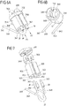
- eine gesonderte Ansicht einer Baugruppe umfassend zwei Kontaktelemente des Steckverbinderteils und eine Kühlungseinrichtung zur Kühlung der Kontaktelemente;
- Fig. 5B
- eine andere Ansicht der Baugrube gemäß
Fig. 5A ; - Fig. 6A
- eine gesonderte Ansicht der Kühlungseinrichtung;
- Fig. 6B
- eine andere Ansicht der Kühlungseinrichtung;
- Fig. 7
- eine Explosionsansicht der Kühlungseinrichtung; und
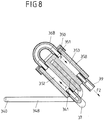
- Fig. 8
- eine Schnittansicht durch einen Kühlkörper der Kühlungseinrichtung.
-
Fig. 1 zeigt eine Ladestation 1, die zum Aufladen eines elektrisch angetriebenen Fahrzeugs 4, auch bezeichnet als Elektrofahrzeug, dient. Die Ladestation 1 ist dazu ausgestaltet, einen Ladestrom in Form eines Wechselstroms oder eines Gleichstroms zur Verfügung zu stellen und weist ein Kabel 2 auf, das mit einem Ende 201 mit der Ladestation 1 und mit einem anderen Ende 200 mit einem Steckverbinderteil 3 in Form eines Ladesteckers verbunden ist. - Wie aus der vergrößerten Ansicht gemäß
Fig. 2 ersichtlich, weist das Steckverbinderteil 3 an einem Gehäuse 30 Steckabschnitte 300, 301 auf, mit denen das Steckverbinderteil 3 steckend mit einem zugeordneten Gegensteckverbinderteil 40 in Form einer Ladebuchse an dem Fahrzeug 4 in Eingriff gebracht werden kann. Auf diese Weise kann die Ladestation 1 elektrisch mit dem Fahrzeug 4 verbunden werden, um Ladeströme von der Ladestation 1 hin zu dem Fahrzeug 4 zu übertragen. - Um ein zügiges Aufladen des Elektrofahrzeugs 4 z.B. im Rahmen eines sogenannten Schnellladevorgangs zu ermöglichen, weisen die übertragenen Ladeströme eine große Stromstärke, z.B. größer als 200 A, gegebenenfalls sogar in der Größenordnung von 350 A oder darüber, auf. Aufgrund solch hoher Ladeströme kommt es an dem Kabel 2 und auch am Steckverbinderteil 3 sowie der Ladebuchse 40 zu thermischen Verluste, die zu einem Erwärmen des Kabels 2, des Steckverbinderteils 3 und der Ladebuchse 40 führen können.
- Das Steckverbinderteil 3 weist, an seinen Steckabschnitten 300, 301, eine Mehrzahl von Kontaktelementen auf. Beispielsweise können an dem Steckabschnitt 301 zwei Kontaktelemente zum Übertragen eines Ladestroms in Form eines Gleichstroms angeordnet sein, während an dem Steckabschnitt 300 beispielsweise fünf Kontaktelemente zur Bereitstellung von fünf Lastkontakten vorgesehen sind, um einen (z.B. mehrphasigen) Wechselstrom zu übertragen.
- Bei einem konkreten, in
Fig. 3 dargestellten Ausführungsbeispiel eines Steckverbinderteils sind an einem unteren Steckabschnitt 301 innerhalb von zwei Steckzapfen 302 Kontaktelemente 31A, 31B angeordnet, die zum Übertragen eines Ladestroms in Form eines Gleichstroms dienen. An dem anderen, oberen Steckabschnitt 300 sind demgegenüber in Steckzapfen 303 Kontaktelemente 32 angeordnet, die zum Übertragen eines Wechselstroms dienen. Das Steckverbinderteil 3 ist somit als so genannter Kombi-Stecker ausgebildet, der wahlweise zum Übertragen von Gleichströmen oder Wechselströmen dienen kann. - Wie schematisch in
Fig. 3 dargestellt, können die Kontaktelemente 31A, 31B an dem Steckabschnitt 301 des Steckverbinderteils 3 in eine Einsteckrichtung E mit Gegenkontaktelementen 400 in Form von Kontaktstiften auf Seiten der Ladebuchse 40 steckend in Eingriff gebracht werden, um die Kontaktelemente 31A, 31B mit den Gegenkontaktelementen 400 elektrisch zu kontaktieren. - In dem Kabel 2 sind Lastleitungen 20, 21 geführt, die zum Übertragen eines Laststroms hin zu dem Steckverbinderteil 3 dienen. Mit jedem Kontaktelement 31A, 31B ist eine Lastleitung 20 verbunden. Eine weitere Lastleitung 21 dient zum Bestromen der Kontaktelemente 33 an dem anderen, oberen Steckabschnitt 300.
- Um bei dem Ausführungsbeispiel des Steckverbinderteils 3 gemäß
Fig. 3 an den Kontaktelementen 31A, 31B an dem unteren Steckabschnitt 301 eine Kühlung zu bewirken, sind, wie aus der Teilschnittansicht gemäßFig. 4 sowie den Ansichten gemäßFig. 5A ,5B bis 8 ersichtlich, Kühlkörper 35A, 35B vorgesehen, die über Wärmeleitungen 34A, 34B mit den Kontaktelementen 31A, 31B verbunden sind. Über die Wärmeleitungen 34A, 34B kann Wärme an den Kontaktelementen 31A, 31B aufgenommen und hin zu den Kühlkörpern 35A, 35B geleitet werden, um auf diese Weise Wärme von den Kontaktelementen 31A, 31B abzuführen. - Wie aus den Ansichten gemäß
Fig. 5A und 5B ersichtlich, ist jedem Kontaktelement 31A, 31B ein Kühlkörper 35A, 35B zugeordnet. Jedes Kontaktelement 31A, 31B weist einen durch federnde Lamellen gebildeten Buchsenabschnitt 310 auf, an den ein Schaft 311 anschließt. An diesem Schaft 311 ist ein Anschlussstück 33A, 33B angeordnet, indem der zylindrische Schaft 311 eine Öffnung 330 an dem Anschlussstück 33A, 33B durchgreift. Die dem jeweiligen Kontaktelement 31A, 31B zugeordnete Wärmeleitung 34A, 34B ist mit einem Ende 340 in eine Öffnung 331 des Anschlussstücks 33A, 33B eingesteckt und erstreckt sich von dem Kontaktelement 31A, 31B hin zu dem zugeordneten Kühlkörper 35A, 35B, in den die Wärmeleitung 34A, 34B mit einem dem Ende 340 abliegenden Ende 341 eingesteckt ist. - Das Kontaktelement 31A, 31B ist aus einem Metall, beispielsweise einem Kupfermaterial, hergestellt. Um eine gute Wärmeübertragung von dem Kontaktelement 31A, 31B zu bewirken, sind das Anschlussstück 33A, 33B, die Wärmeleitung 34A, 34B und der Kühlkörper 35A, 35B vorteilhafterweise ebenfalls aus einem Metall gefertigt, insbesondere einem Metall, das eine gute Wärmeleitfähigkeit aufweist. Das Anschlussstück 33A, 33B, die Wärmeleitung 34A, 34B und der Kühlkörper 35A, 35B sind hierbei als massive, metallene Teile ausgebildet, sodass insbesondere der Kühlkörper 35A, 35B eine vergleichsweise große Wärmekapazität aufweist.
- Jedem Kontaktelement 31A, 31B ist ein gesonderter Kühlkörper 35A, 35B zugeordnet. Die einzelnen Kühlkörper 35A, 35B werden durch ein aus einem elektrisch isolierenden Material, beispielsweise Kunststoff, gefertigtes Verbindungselement 350 in Position zueinander gehalten derart, dass sich die Kühlkörper 35A, 35B nicht gegenseitig berühren. Dadurch, dass die Kühlkörper 35A, 35B der einzelnen Kontaktelemente 31A, 31B somit räumlich voneinander separiert sind, ist sichergestellt, dass die elektrische Isolation zwischen den Kontaktelementen 31A, 31B durch die an die Kontaktelemente 31A, 31B angeschlossenen Kühlkörper 35A, 35B nicht beeinträchtigt ist.
- Die Wärmeleitungen 34A, 34B sind mit ihren Enden 341 in Öffnungen 351 in Form von Sacklöchern an den Kühlkörpern 35A, 35B eingesteckt und auf diese Weise fest mit den zugeordneten Kühlkörpern 35A, 35B verbunden. Die Verbindung ist hierbei derart, dass Wärme in günstiger Weise von den Wärmeleitungen 34A, 34B auf die Kühlkörper 35A, 35B übertragen werden kann.
- Die Anschlusstücke 33A, 33B sind fest, beispielsweise formschlüssig, kraftschlüssig (durch Verpressen) oder stoffschlüssig (z.B. durch Schweißen), mit dem Schaft 311 des jeweils zugeordneten Kontaktelements 31A, 31B verbunden. Ebenso können die Wärmeleitungen 34A, 34B fest, z.B. stoffschlüssig (z.B. durch Schweißen), einerseits mit dem zugeordneten Anschlussstück 33A, 33B und andererseits mit dem zugeordneten Kühlkörper 35A, 35B verbunden sein.
- Bei dem dargestellten Ausführungsbeispiel sind die Kühlkörper 35A, 35B, die wie in
Fig. 4 dargestellt innerhalb des Gehäuses 30 angeordnet sind, aktiv gekühlt. Hierzu weisen die Kühlkörper 35A, 35B, wie insbesondere ausFig. 7 und8 ersichtlich, jeweils zwei längserstreckte, parallel zueinander verlaufende Fluidkanäle 352, 353 auf, durch die ein (gasförmiges oder flüssiges) Kühlmittel strömen kann, um Wärme an den Kühlkörpern 35A, 35B aufzunehmen und von den Kühlkörpern 35A, 35B abzuführen. - Die Fluidkanäle 352, 353 der unterschiedlichen Kühlkörper 35A, 35B können in serieller Weise oder in paralleler Weise miteinander verschaltet werden, um einen Kühlmittelkreislauf zum Kühlen bereitzustellen. Denkbar und möglich ist auch, jeden Kühlkörper 35A, 35B mit einem eigenen Kühlmittelkreislauf zu verbinden. Hierzu können Kühlmittelleitungen 38, 39 an die Kühlkörper 35A, 35B angeschlossen werden, sodass über eine Kühlmittelleitung 38 ein Kühlmittel in eine Flussrichtung F1 zugeleitet und über eine andere Kühlmittelleitung 39 in eine Flussrichtung F2 wieder abgeleitet werden kann.
- Bei dem dargestellten Ausführungsbeispiel sind die Fluidkanäle 352, 353 der Kühlmittelkörper 35A, 35B seriell miteinander strömungsverbunden, sodass ein zugeleitetes Kühlmittel die Fluidkanäle 352, 353 der Kühlkörper 35A, 35B in serieller Weise durchströmt.
- So sind bei dem dargestellten Ausführungsbeispiel die Fluidkanäle 352, 353 eines jeden Kühlkörpers 35A, 35B über eine Umlenkleitung 36A, 36B miteinander strömungsverbunden, sodass ein in einen Fluidkanal 353 eingeleitetes Kühlmittel über die Umlenkleitung 36A, 36B umgelenkt wird und durch den anderen Fluidkanal 352 zurückströmt. Die Fluidkanäle 352, 353 sind beidseits der Öffnung 351, in die die zugeordnete Wärmeleitung 34A, 24B eingesteckt ist, angeordnet, sodass über die Fluidkanäle 352, 353 Wärme beidseits der Wärmeleitung 34A, 34B aufgenommen und abgeführt werden kann.
- Zusätzlich sind der Fluidkanal 352 des einen Kühlkörpers 35A und der Fluidkanal 352 des anderen Kühlkörpers 35B über eine Umlenkleitung 37 miteinander strömungsverbunden, sodass ein Kühlmittel aus dem Fluidkanal 352 des einen Kühlkörpers 35A über die Umlenkleitung 37 in den Fluidkanal 352 des anderen Kühlkörpers 35B einströmen kann.
- Zur Komplettierung des Kühlmittelkreislaufs ist eine erste Kühlmittelleitung 38 mit dem Fluidkanal 353 des einen Kühlkörpers 35A verbunden und dient beispielsweise zum Zuleiten eines Kühlmittels. Eine andere, zweite Kühlmittelleitung 39 ist demgegenüber mit dem Kühlkörper 353 des anderen Kühlkörpers 35B verbunden und dient zum Ableiten des Kühlmittels. Ein Kühlmittel kann somit über die Kühlmittelleitung 38 zugeführt werden und in den Fluidkanal 353 des Kühlkörpers 35A einströmen. Über die Umlenkleitung 36A wird das Kühlmittel in den Fluidkanal 352 des Kühlkörpers 35A und von dort über die Umleitung 37 in den Fluidkanal 352 des Kühlkörpers 35B geleitet, strömt über den Fluidkanal 352 des Kühlkörpers 35B und die Umlenkleitung 36B in Flussrichtung F (siehe
Fig. 8 ) in den Fluidkanal 353 des Kühlkörpers 35B und wird über die Kühlmittelleitung 39 abgeleitet. Die Fluidkanäle 352, 353 der Kühlkörper 35A, 35B werden somit seriell durchströmt, sodass Wärme an den Kühlkörpern 35A, 35B aufgenommen und abgeleitet werden kann. - Die Kühlmittelleitung 38, 39 sind in dem Kabel 2 verlegt und durch einen Kabelschlauch des Kabels 2 eingefasst. Die Kühlmittelleitung 38, 39 werden auf diese Weise hin zu der Ladestation 1 geführt und sind auf Seiten der Ladestation 1 beispielsweise mit einer Kühlmittelpumpe verbunden, um einen Kühlmittelstrom durch die Kühlmittelleitungen 38, 39 zu bewirken.
- Der der Erfindung zugrunde liegende Gedanke ist nicht auf die vorangehend geschilderten Ausführungsbeispiele beschränkt, sondern lässt sich kontert sich auch in gänzlich andersgearteter Weise verwirklichen.
- Grundsätzlich können sämtliche Kontaktelemente des Steckverbinderteils auf die beschriebene Weise gekühlt werden. Denkbar und möglich ist jedoch auch, dass nur einzelne Kontaktelemente gekühlt werden.
- Das Steckverbinderteil kann einen oder mehrere Kühlkörper, insbesondere auch mehr als zwei Kühlkörper, aufweisen. Eine Kühlung kann hierbei nicht nur an zur Übertragung eines Gleichstroms vorgesehenen Kontaktelementen erfolgen, sondern auch an Kontaktelementen, die zum Übertragen eines Wechselstroms dienen.
-
- 1
- Ladestation
- 2
- Ladekabel
- 20, 21
- Lastleitung
- 22
- Signalleitung
- 200, 201
- Ende
- 3
- Ladestecker
- 30
- Gehäuse
- 300, 301
- Steckabschnitt
- 302, 303
- Steckzapfen
- 31A, 31B
- Kontaktelement
- 310
- Buchsenabschnitt
- 311
- Schaft
- 32
- Kontaktelement
- 33A, 33B
- Anschlussstück
- 330, 331
- Öffnung
- 34A, 34B
- Wärmeleitung
- 340, 341
- Ende
- 35A, 35B
- Kühlkörper
- 350
- Verbindungselement
- 351
- Öffnung (Sackloch)
- 352, 353
- Fluidkanal
- 36A, 36B
- Umlenkleitung
- 37
- Umlenkleitung
- 38, 39
- Kühlmittelleitung
- 4
- Fahrzeug
- 40
- Ladebuchse
- 400
- Gegenkontaktelement
- E
- Einsteckrichtung
- F, F1, F2
- Flussrichtung
Claims (9)
- Steckverbinderteil (3) zum Verbinden mit einem Gegensteckverbinderteil (40), mit- einem Gehäuse (30), das einen Steckabschnitt (300, 301) zum steckenden Verbinden mit dem Gegensteckverbinderteil (40) aufweist,- zumindest einem an dem Steckabschnitt (300, 301) angeordneten Kontaktelement (31A, 31B) zum elektrischen Kontaktieren mit einem zugeordneten Gegenkontaktelement (400) des Gegensteckverbinderteils (40),- einer an das zumindest eine Kontaktelement (31A, 31B) angeschlossenen Wärmeleitung (34A, 34B) und- einem in dem Gehäuse (30) angeordneten Kühlkörper (35A, 35B), der zum Abführen von Wärme von dem zumindest einen Kontaktelement (31A, 31B) über die Wärmeleitung (34A, 34B) mit dem zumindest einen Kontaktelement (31A, 31B) in Wärmeleitverbindung steht,dadurch gekennzeichnet, dass die Wärmeleitung (34A, 34B) mit einem ersten Ende (340) in eine Öffnung (331) eines metallischen Anschlussstücks (33A, 33B) eingesteckt und über das Anschlussstück (33A, 33B) mit dem zugeordneten Kontaktelement (31A, 31B) verbunden ist.
- Steckverbinderteil (3) nach Anspruch 1, dadurch gekennzeichnet, dass das Steckverbinderteil (3) eine Mehrzahl von an dem Steckabschnitt (300, 301) angeordneten Kontaktelemente (31A, 31B) aufweist, wobei jedem Kontaktelement (31A, 31B) ein Kühlkörper (35A, 35B) zugeordnet ist, der über eine Wärmeleitung (34A, 34B) mit dem zugeordneten Kontaktelement (31A, 31B) in Wärmeleitverbindung steht.
- Steckverbinderteil (3) nach Anspruch 1 oder 2, dadurch gekennzeichnet, dass die Wärmeleitung (34A, 34B) und/oder der Kühlkörper (35A, 35B) aus Metall gefertigt sind.
- Steckverbinderteil (3) nach einem der vorangehenden Ansprüche, dadurch gekennzeichnet, dass die Wärmeleitung (34A, 34B) mit einem zweiten Ende (340) in eine Öffnung (351) des Kühlkörpers (35A, 35B) eingesteckt ist.
- Steckverbinderteil (3) nach einem der vorangehenden Ansprüche, dadurch gekennzeichnet, dass der Kühlkörper (35A, 35B) einen mit einem Kühlmittel durchströmbaren Fluidkanal (352, 353) aufweist.
- Steckverbinderteil (3) nach einem der vorangehenden Ansprüche, dadurch gekennzeichnet, dass der Kühlkörper (35A, 35B) zwei Fluidkanäle (352, 353) aufweist, die über eine mit dem Kühlkörper (35A, 35B) verbundene Umlenkleitung (36A, 36B) miteinander strömungsverbunden sind.
- Steckverbinderteil (3) nach einem der vorangehenden Ansprüche, dadurch gekennzeichnet, dass ein Fluidkanal (352) eines einem ersten Kontaktelement (31A) zugeordneten, ersten Kühlkörpers (35A) über eine Umlenkleitung (37) mit einem Fluidkanal (352) eines einem zweiten Kontaktelement (31B) zugeordneten, zweiten Kühlkörpers (35B) verbunden ist.
- Steckverbinderteil (3) nach Anspruch 7, dadurch gekennzeichnet, dass eine in einem mit dem Steckverbinderteil (3) verbundenen Kabel (2) geführte, erste Kühlmittelleitung (38) zum Zuführen eines Kühlmittels mit dem ersten Kühlkörper (35A) und eine in dem Kabel (2) geführte, zweite Kühlmittelleitung (39) zum Abführen des Kühlmittels mit dem zweiten Kühlkörper (35B) verbunden ist.
- Steckverbinderteil (3) nach einem der vorangehenden Ansprüche, dadurch gekennzeichnet, dass mehrere Kühlkörper (35A, 35B) über ein Verbindungselement (350) miteinander verbunden sind und über das Verbindungselement (350) derart auf Abstand zueinander gehalten werden, dass die Kühlkörper (35A, 35B) sich nicht gegenseitig berühren.
Applications Claiming Priority (2)
| Application Number | Priority Date | Filing Date | Title |
|---|---|---|---|
| DE102016107409.8A DE102016107409A1 (de) | 2016-04-21 | 2016-04-21 | Steckverbinderteil mit einem gekühlten Kontaktelement |
| PCT/EP2017/059216 WO2017182484A1 (de) | 2016-04-21 | 2017-04-19 | Steckverbinderteil mit einem gekühlten kontaktelement |
Publications (2)
| Publication Number | Publication Date |
|---|---|
| EP3446372A1 EP3446372A1 (de) | 2019-02-27 |
| EP3446372B1 true EP3446372B1 (de) | 2021-03-10 |
Family
ID=58549145
Family Applications (1)
| Application Number | Title | Priority Date | Filing Date |
|---|---|---|---|
| EP17718071.8A Active EP3446372B1 (de) | 2016-04-21 | 2017-04-19 | Steckverbinderteil mit einem gekühlten kontaktelement |
Country Status (7)
| Country | Link |
|---|---|
| US (1) | US10644439B2 (de) |
| EP (1) | EP3446372B1 (de) |
| JP (1) | JP6721711B2 (de) |
| CN (1) | CN109075498B (de) |
| DE (1) | DE102016107409A1 (de) |
| PT (1) | PT3446372T (de) |
| WO (1) | WO2017182484A1 (de) |
Cited By (5)
| Publication number | Priority date | Publication date | Assignee | Title |
|---|---|---|---|---|
| DE102022124509A1 (de) | 2022-09-23 | 2024-03-28 | Kiekert Aktiengesellschaft | Steckverbinderteil zur mechanischen und elektrischen Verbindung mit einem Gegensteckverbinderteil |
| DE102022124644A1 (de) | 2022-09-26 | 2024-03-28 | Kiekert Aktiengesellschaft | Steckverbinderteil zur mechanischen und elektrischen Verbindung mit einem Gegensteckverbinderteil |
| WO2025077956A1 (de) * | 2023-10-12 | 2025-04-17 | Kiekert Aktiengesellschaft | System mit einem ladesteckverbinder für elektro- und hybridfahrzeuge |
| WO2025077954A1 (de) * | 2023-10-12 | 2025-04-17 | Kiekert Aktiengesellschaft | System mit einem ladesteckverbinder für elektro- und hybridfahrzeuge |
| EP4516574A3 (de) * | 2023-08-31 | 2025-05-14 | Siemens Aktiengesellschaft | Ladevorrichtung zum laden eines elektrofahrzeugs |
Families Citing this family (76)
| Publication number | Priority date | Publication date | Assignee | Title |
|---|---|---|---|---|
| DE102017222808A1 (de) * | 2017-12-14 | 2019-06-19 | Phoenix Contact E-Mobility Gmbh | Lastkontaktmodul und Ladestecker |
| DE102018100827A1 (de) * | 2018-01-16 | 2019-07-18 | Dr. Ing. H.C. F. Porsche Aktiengesellschaft | Ladekabel und Ladestation für Elektroautos |
| USD925443S1 (en) * | 2018-01-24 | 2021-07-20 | Phoenix Contact E-Mobility Gmbh | Electric vehicle charging connector |
| DE102018102207A1 (de) * | 2018-02-01 | 2019-08-01 | Dr. Ing. H.C. F. Porsche Aktiengesellschaft | Kraftfahrzeugladekabel |
| JP7006483B2 (ja) * | 2018-04-24 | 2022-02-10 | トヨタ自動車株式会社 | コネクタ |
| CH715611B1 (de) * | 2018-12-05 | 2022-05-13 | BRUGG eConnect AG | Anschlusselement zum elektrischen Anschliessen einer fluidkühlbaren Einzelleitung, fluidkühlbare Einzelleitungseinheit und Ladekabel. |
| US11387598B2 (en) * | 2019-02-19 | 2022-07-12 | Aptiv Technologies Limited | Electrical connector assembly with modular cooling features |
| US10988041B2 (en) * | 2019-03-27 | 2021-04-27 | Te Connectivity Corporation | Cable heat exchanger for a power connector |
| US11590855B2 (en) * | 2019-04-26 | 2023-02-28 | Hanon Systems | Electric vehicle fast charging and battery cooling system using a charger cooled fluid-to-battery cooled fluid heat exchange device |
| NL2023045B1 (en) * | 2019-05-01 | 2020-12-02 | Prysmian Spa | Cable assembly |
| JP7163865B2 (ja) * | 2019-05-14 | 2022-11-01 | 株式会社オートネットワーク技術研究所 | 接続端子及びコネクタ |
| US11285832B2 (en) * | 2019-06-05 | 2022-03-29 | TE Connectivity Services Gmbh | Heat exchanger for a power connector |
| DE102019209467A1 (de) * | 2019-06-28 | 2020-12-31 | Audi Ag | Ladestecker für eine Ladestation zum Übertragen von elektrischer Energie sowie ein Ladesystem hierzu |
| DE102019117649A1 (de) | 2019-07-01 | 2021-01-07 | Phoenix Contact E-Mobility Gmbh | Aktiv gekühltes Ladesteckverbinderteil |
| EP3767752B1 (de) | 2019-07-18 | 2026-02-18 | Rosenberger Hochfrequenztechnik GmbH & Co. KG | Konfektioniertes elektrisches kabel, verfahren zur konfektionierung eines elektrischen kabels und elektrische steckverbindung |
| US11469531B2 (en) * | 2019-07-19 | 2022-10-11 | Yazaki North America, Inc. | Liquid-cooled charging system for a vehicle |
| EP3770005B8 (de) | 2019-07-25 | 2023-12-06 | ABB E-mobility B.V. | Elektrofahrzeugladesystem zum laden eines elektrofahrzeugs |
| US11846475B2 (en) * | 2019-08-26 | 2023-12-19 | Te Connectivity Solutions Gmbh | Heat exchanger for a power connector |
| EP3904149B1 (de) * | 2020-04-27 | 2026-04-15 | ABB E-mobility B.V. | Ladesteckerdüse |
| DE102020206416A1 (de) | 2020-05-22 | 2021-11-25 | Te Connectivity Germany Gmbh | Kühlvorrichtung für ein Steckverbinderelement und Steckverbinderelement für Hochvoltanwendungen |
| US11951857B2 (en) * | 2020-11-04 | 2024-04-09 | Ford Global Technologies, Llc | Liquid cooled electrical connectors |
| EP4000992B1 (de) * | 2020-11-19 | 2026-01-07 | ABB E-mobility B.V. | Fahrzeugladestation |
| EP4000991B1 (de) * | 2020-11-19 | 2024-08-14 | ABB E-mobility B.V. | Ladeverbinder für elektrofahrzeuge mit externer passiver kühlung |
| EP4000989A1 (de) * | 2020-11-19 | 2022-05-25 | ABB Schweiz AG | Ladeverbinder für elektrofahrzeuge und wärmerohr |
| EP4000990A1 (de) * | 2020-11-19 | 2022-05-25 | ABB Schweiz AG | Elektrofahrzeugladeverbinder mit aktiver kühlung |
| FR3117662B1 (fr) * | 2020-12-14 | 2023-03-03 | Valeo Systemes Thermiques | Elément de refroidissement pour câble de charge électrique d’un dispositif de stockage d’énergie électrique et procédé de mise en place correspondant. |
| US20240067008A1 (en) * | 2021-01-11 | 2024-02-29 | Designwerk Technologies Ag | Charging inlet |
| CN114763074A (zh) * | 2021-01-14 | 2022-07-19 | 台达电子工业股份有限公司 | 多充电连接器的液冷充电设备及其操作方法 |
| DE102021101528A1 (de) | 2021-01-25 | 2022-07-28 | Phoenix Contact E-Mobility Gmbh | Hochstrommodul für Ladesteckverbinderteil |
| EP4123253B1 (de) * | 2021-07-20 | 2023-07-12 | Rosenberger Hochfrequenztechnik GmbH & Co. KG | Mehrschichtiger latentwärmespeicher |
| EP4151448A1 (de) * | 2021-09-21 | 2023-03-22 | ABB E-mobility B.V. | Ladestecker mit passiver kühlung und temperatursensor eines elektrischen fahrzeugs |
| EP4151454A1 (de) * | 2021-09-21 | 2023-03-22 | ABB E-mobility B.V. | Kontaktelementanordnung für einen ev-steckverbinder mit einem wärmerohr |
| USD1002543S1 (en) * | 2021-09-29 | 2023-10-24 | Jiangsu Yihang Electric Technology Co., Ltd. | DC charging gun |
| US12232296B2 (en) * | 2021-10-21 | 2025-02-18 | Luxshare Precision Industry (Jiangsu) Co., Ltd. | Liquid cooling system of charging gun and charging gun |
| USD998571S1 (en) * | 2021-10-27 | 2023-09-12 | Ti-Lane Precision Electronic Co., Ltd. | Vehicle charging connector |
| EP4186742A1 (de) * | 2021-11-25 | 2023-05-31 | ABB E-mobility B.V. | Ev-ladeverbinder mit thermischer trägheit und verfahren |
| EP4197848A1 (de) * | 2021-12-15 | 2023-06-21 | ABB E-mobility B.V. | Elektrofahrzeug-ladeverbinder und elektrofahrzeug-ladestation |
| DE102022103222A1 (de) | 2022-02-11 | 2023-08-17 | Phoenix Contact E-Mobility Gmbh | Steckverbinderteil für ein Ladesystem zum Aufladen eines Elektrofahrzeugs |
| BE1030267B1 (de) | 2022-02-11 | 2023-09-11 | Phoenix Contact E Mobility Gmbh | Steckverbinderteil für ein Ladesystem zum Aufladen eines Elektrofahrzeugs |
| BE1030266B1 (de) | 2022-02-11 | 2023-09-11 | Phoenix Contact E Mobility Gmbh | Steckverbinderteil für ein Ladesystem zum Aufladen eines Elektrofahrzeugs |
| DE102022103224A1 (de) | 2022-02-11 | 2023-08-17 | Phoenix Contact E-Mobility Gmbh | Steckverbinderteil für ein Ladesystem zum Aufladen eines Elektrofahrzeugs |
| DE102022105188A1 (de) | 2022-03-04 | 2023-09-07 | iinovis GmbH | Vorrichtung zum elektrischen Verbinden einer Ladedose mit einer elektrischen Speichereinrichtung |
| DE102022124506A1 (de) | 2022-09-23 | 2024-03-28 | Kiekert Aktiengesellschaft | Ladesteckverbinder für Elektro- und Hybridfahrzeuge |
| CN115303096B (zh) * | 2022-10-11 | 2023-01-06 | 广州万城万充新能源科技有限公司 | 超充充电端子多流道液冷装置及超充充电枪 |
| DE102022128014A1 (de) | 2022-10-24 | 2024-04-25 | Phoenix Contact E-Mobility Gmbh | Kontaktbaugruppe für einen elektrischen Steckverbinder mit einem an einem Kontaktelement angeordneten Wärmekapazitätselement |
| DE102022128015A1 (de) | 2022-10-24 | 2024-04-25 | Phoenix Contact E-Mobility Gmbh | Kontaktbaugruppe für einen elektrischen Steckverbinder mit einem an einer Lastleitung angeordneten Wärmekapazitätselement |
| BE1030985B1 (de) | 2022-10-24 | 2024-05-27 | Phoenix Contact E Mobility Gmbh | Kontaktbaugruppe für einen elektrischen Steckverbinder mit einem an einer Lastleitung angeordneten Wärmekapazitätselement |
| BE1030984B1 (de) | 2022-10-24 | 2024-05-27 | Phoenix Contact E Mobility Gmbh | Kontaktbaugruppe für einen elektrischen Steckverbinder mit einem an einem Kontaktelement angeordneten Wärmekapazitätselement |
| DE102022129024A1 (de) | 2022-11-03 | 2024-05-08 | Phoenix Contact E-Mobility Gmbh | Kontaktbaugruppe für einen elektrischen Steckverbinder |
| BE1031015B1 (de) | 2022-11-03 | 2024-06-04 | Phoenix Contact E Mobility Gmbh | Kontaktbaugruppe für einen elektrischen Steckverbinder |
| DE102022129025A1 (de) | 2022-11-03 | 2024-05-08 | Phoenix Contact E-Mobility Gmbh | Kontaktbaugruppe für einen elektrischen Steckverbinder |
| DE102022132872A1 (de) * | 2022-12-09 | 2024-06-20 | Kiekert Aktiengesellschaft | Ladesteckverbinder für Elektro- und Hybridfahrzeuge |
| DE102022133099A1 (de) * | 2022-12-13 | 2024-06-13 | Lisa Dräxlmaier GmbH | Ladedose für ein fahrzeug |
| DE102022134269A1 (de) | 2022-12-21 | 2024-06-27 | Kiekert Aktiengesellschaft | Ladesteckverbinder für Elektro- und Hybridfahrzeuge |
| DE102023100825A1 (de) | 2023-01-16 | 2024-07-18 | Kiekert Aktiengesellschaft | System aus Ladekontakt und Latentwärmespeicher für Elektro- und Hybridfahrzeuge |
| BE1031286B1 (de) | 2023-01-23 | 2024-08-19 | Phoenix Contact E Mobility Gmbh | Steckverbinderteil für ein Ladesystem zum Aufladen eines Elektrofahrzeugs |
| DE102023101571A1 (de) | 2023-01-23 | 2024-07-25 | Phoenix Contact E-Mobility Gmbh | Steckverbinderteil für ein Ladesystem zum Aufladen eines Elektrofahrzeugs |
| DE102023101873A1 (de) | 2023-01-26 | 2024-08-01 | Phoenix Contact E-Mobility Gmbh | Steckverbinderteil für ein Ladesystem zum Aufladen eines Elektrofahrzeugs |
| DE102023101872A1 (de) | 2023-01-26 | 2024-08-01 | Phoenix Contact E-Mobility Gmbh | Steckverbinderteil für ein Ladesystem zum Aufladen eines Elektrofahrzeugs |
| DE102023103133A1 (de) | 2023-02-09 | 2024-08-14 | Phoenix Contact E-Mobility Gmbh | Steckverbinderteil für ein Ladesystem zum Aufladen eines Elektrofahrzeugs |
| DE102023105180A1 (de) | 2023-03-02 | 2024-09-05 | Kiekert Aktiengesellschaft | Ladesteckverbinder für Elektro- und Hybridfahrzeuge |
| DE102023111407A1 (de) | 2023-05-03 | 2024-11-07 | Kiekert Aktiengesellschaft | Ladesteckverbinder für Elektro- und Hybridfahrzeuge |
| CN118899684A (zh) * | 2023-05-04 | 2024-11-05 | 泰科电子(苏州)有限公司 | 电连接件和电连接组件 |
| DE102023111566A1 (de) | 2023-05-04 | 2024-11-07 | Phoenix Contact E-Mobility Gmbh | Steckverbinderteil für ein Ladesystem zum Aufladen eines Elektrofahrzeugs |
| LU504123B1 (de) | 2023-05-04 | 2024-11-04 | Phoenix Contact E Mobility Gmbh | Steckverbinderteil für ein Ladesystem zum Aufladen eines Elektrofahrzeugs |
| DE102023119896A1 (de) | 2023-07-27 | 2025-01-30 | Kiekert Aktiengesellschaft | Ladesteckverbinder für Elektro- und Hybridfahrzeuge |
| DE102023124596A1 (de) | 2023-09-12 | 2025-03-13 | Kiekert Aktiengesellschaft | System mit einem Ladesteckverbinder für Elektro- und Hybridfahrzeuge und einem Wärmespeicher |
| DE102023124960A1 (de) | 2023-09-15 | 2025-03-20 | Phoenix Contact E-Mobility Gmbh | Ladesteckverbinderteil für ein Ladesystem zum Aufladen eines Elektrofahrzeugs |
| LU505131B1 (de) | 2023-09-19 | 2025-03-20 | Phoenix Contact E Mobility Gmbh | Baugruppe eines Ladesystem zum Aufladen eines Elektrofahrzeugs |
| DE102023125297A1 (de) | 2023-09-19 | 2025-03-20 | Phoenix Contact E-Mobility Gmbh | Baugruppe eines Ladesystem zum Aufladen eines Elektrofahrzeugs |
| DE102023126241A1 (de) | 2023-09-27 | 2025-03-27 | Kiekert Aktiengesellschaft | Ladesteckverbinder für Elektro- und Hybridfahrzeuge |
| DE102023127888A1 (de) | 2023-10-12 | 2025-04-17 | Kiekert Aktiengesellschaft | System mit einem Ladesteckverbinder für Elektro- und Hybridfahrzeuge |
| DE102024110074A1 (de) | 2024-04-11 | 2025-10-16 | Kiekert Aktiengesellschaft | Ladesteckverbinder für Elektro- und Hybridfahrzeuge |
| DE102024113418A1 (de) | 2024-05-14 | 2025-11-20 | Kiekert Aktiengesellschaft | Ladesteckverbinder für Elektro- und Hybridfahrzeuge |
| EP4650213A1 (de) * | 2024-05-15 | 2025-11-19 | K.S. Terminals Inc. | Flüssigkeitsgekühlter ladestecker |
| DE102024126749A1 (de) | 2024-09-17 | 2026-03-19 | Phoenix Contact E-Mobility Gmbh | Ladesteckverbinderteil für ein Ladesystem zum Aufladen eines Elektrofahrzeugs |
Family Cites Families (21)
| Publication number | Priority date | Publication date | Assignee | Title |
|---|---|---|---|---|
| JPH08148239A (ja) * | 1994-11-25 | 1996-06-07 | Japan Aviation Electron Ind Ltd | コネクタ |
| EP0823767A1 (de) | 1996-08-07 | 1998-02-11 | SUMITOMO WIRING SYSTEMS, Ltd. | Ladesystem für elektrisches Fahrzeug |
| DE19819903C2 (de) * | 1998-05-05 | 2000-09-14 | Didier Werke Ag | Fluidgekühlte, elektrische Stromleitung |
| DE10127488A1 (de) * | 2001-06-07 | 2003-01-16 | Siemens Ag | Verfahren zum Erzeugen eines Steckverbinders und Steckverbinder |
| DE20203315U1 (de) * | 2002-03-01 | 2003-07-10 | Robert Bosch Gmbh, 70469 Stuttgart | Flachsteckerumspritzung, insbesondere im Bereich des Flachsteckeraustritts |
| US7105858B2 (en) * | 2002-08-26 | 2006-09-12 | Onscreen Technologies | Electronic assembly/system with reduced cost, mass, and volume and increased efficiency and power density |
| KR100684761B1 (ko) * | 2005-03-21 | 2007-02-20 | 삼성에스디아이 주식회사 | 이차전지 모듈 |
| JP4785878B2 (ja) * | 2008-02-06 | 2011-10-05 | 本田技研工業株式会社 | 冷却装置及び該冷却装置を備える電気車両 |
| EP2104183A1 (de) * | 2008-03-18 | 2009-09-23 | ABB Schweiz AG | Elektrische Verbindungseinrichtung und Verbinder |
| DE102010007975B4 (de) | 2010-02-15 | 2012-10-04 | Siemens Aktiengesellschaft | Ladestation für einen elektrischen Energiespeicher und zugehöriger elektrischer Energiespeicher |
| DE102010050562B3 (de) * | 2010-11-05 | 2012-04-05 | Volkswagen Aktiengesellschaft | Vorrichtung zum Laden eines mit elektrischer Energie antreibbaren Fahrzeugs |
| US8350526B2 (en) * | 2011-07-25 | 2013-01-08 | Lightening Energy | Station for rapidly charging an electric vehicle battery |
| US10340709B2 (en) * | 2011-07-29 | 2019-07-02 | Lightening Energy | Electric battery rapid recharging system including a mobile charging station having a coolant supply line and an electrical supply line |
| DE102011121133A1 (de) * | 2011-12-13 | 2013-06-13 | Kostal Kontakt Systeme Gmbh | Fluiddichte Kontaktdurchführung |
| US8926360B2 (en) * | 2013-01-17 | 2015-01-06 | Cooper Technologies Company | Active cooling of electrical connectors |
| DE102013221651B4 (de) * | 2013-10-24 | 2023-10-26 | Bayerische Motoren Werke Aktiengesellschaft | Tragbares Ladekabel zum Laden eines Energiespeichers eines elektrisch betriebenen Fahrzeugs |
| US9321362B2 (en) * | 2014-02-05 | 2016-04-26 | Tesia Motors, Inc. | Cooling of charging cable |
| DE102014102197B4 (de) | 2014-02-20 | 2019-02-14 | Phoenix Contact E-Mobility Gmbh | Steckverbinderteil mit einem Rastelement |
| DE102014111185A1 (de) * | 2014-08-06 | 2016-02-11 | Phoenix Contact E-Mobility Gmbh | Steckverbinderteil mit einer Temperatursensoreinrichtung |
| DE102014111831A1 (de) | 2014-08-19 | 2016-02-25 | Phoenix Contact E-Mobility Gmbh | Steckverbinderteil mit Temperatursensoren |
| DE102015016267A1 (de) * | 2015-12-15 | 2016-07-21 | Daimler Ag | Vorrichtung zum Kühlen eines elektrisch leitfähigen Kontaktelements |
-
2016
- 2016-04-21 DE DE102016107409.8A patent/DE102016107409A1/de not_active Ceased
-
2017
- 2017-04-19 WO PCT/EP2017/059216 patent/WO2017182484A1/de not_active Ceased
- 2017-04-19 CN CN201780024390.8A patent/CN109075498B/zh active Active
- 2017-04-19 JP JP2018555206A patent/JP6721711B2/ja not_active Expired - Fee Related
- 2017-04-19 US US16/087,100 patent/US10644439B2/en active Active
- 2017-04-19 PT PT177180718T patent/PT3446372T/pt unknown
- 2017-04-19 EP EP17718071.8A patent/EP3446372B1/de active Active
Non-Patent Citations (1)
| Title |
|---|
| None * |
Cited By (7)
| Publication number | Priority date | Publication date | Assignee | Title |
|---|---|---|---|---|
| DE102022124509A1 (de) | 2022-09-23 | 2024-03-28 | Kiekert Aktiengesellschaft | Steckverbinderteil zur mechanischen und elektrischen Verbindung mit einem Gegensteckverbinderteil |
| WO2024061411A1 (de) | 2022-09-23 | 2024-03-28 | Kiekert Aktiengesellschaft | Steckverbinderteil zur mechanischen und elektrischen verbindung mit einem gegensteckverbinderteil |
| DE102022124644A1 (de) | 2022-09-26 | 2024-03-28 | Kiekert Aktiengesellschaft | Steckverbinderteil zur mechanischen und elektrischen Verbindung mit einem Gegensteckverbinderteil |
| WO2024068604A1 (de) | 2022-09-26 | 2024-04-04 | Kiekert Aktiengesellschaft | Steckverbinderteil zur mechanischen und elektrischen verbindung mit einem gegensteckverbinderteil |
| EP4516574A3 (de) * | 2023-08-31 | 2025-05-14 | Siemens Aktiengesellschaft | Ladevorrichtung zum laden eines elektrofahrzeugs |
| WO2025077956A1 (de) * | 2023-10-12 | 2025-04-17 | Kiekert Aktiengesellschaft | System mit einem ladesteckverbinder für elektro- und hybridfahrzeuge |
| WO2025077954A1 (de) * | 2023-10-12 | 2025-04-17 | Kiekert Aktiengesellschaft | System mit einem ladesteckverbinder für elektro- und hybridfahrzeuge |
Also Published As
| Publication number | Publication date |
|---|---|
| JP6721711B2 (ja) | 2020-07-15 |
| DE102016107409A1 (de) | 2017-10-26 |
| US20190109409A1 (en) | 2019-04-11 |
| CN109075498B (zh) | 2020-07-03 |
| PT3446372T (pt) | 2021-03-17 |
| EP3446372A1 (de) | 2019-02-27 |
| WO2017182484A1 (de) | 2017-10-26 |
| CN109075498A (zh) | 2018-12-21 |
| JP2019515425A (ja) | 2019-06-06 |
| US10644439B2 (en) | 2020-05-05 |
Similar Documents
| Publication | Publication Date | Title |
|---|---|---|
| WO2017182484A1 (de) | Steckverbinderteil mit einem gekühlten kontaktelement | |
| EP3433902B1 (de) | Steckverbinderteil mit einem gekühlten kontaktelement | |
| EP3512736B1 (de) | Steckverbinderteil mit gekühlten kontaktelementen zum laden von elektrischen fahrzeugen | |
| DE202017007235U1 (de) | Steckverbinderteil mit einem gekühlten Kontaktelement | |
| DE102016204895B4 (de) | Ladestecker mit einem Leistungskontaktsystem und Ladestation zur Abgabe elektrischer Energie an einen Empfänger elektrischer Energie | |
| DE202019102461U1 (de) | Steckverbinderteil mit einer Lüftereinrichtung | |
| EP2513987B1 (de) | Thermoelektrische einheit | |
| EP4128441B1 (de) | Steckkontakt | |
| DE102015016267A1 (de) | Vorrichtung zum Kühlen eines elektrisch leitfähigen Kontaktelements | |
| DE102016204894A1 (de) | Ladestecker und Ladestation zur Abgabe elektrischer Energie an einen Empfänger elektrischer Energie | |
| DE102016105361A1 (de) | Steckverbinderteil mit einem gekühlten Kontaktelement | |
| DE102016206300A1 (de) | Ladestecker und ladestation zur abgabe elektrischer energie an einen empfänger elektrischer energie | |
| DE102018125835A1 (de) | Kabelbaugruppe mit einer Kühlleitung und einer Zugentlastungsbaugruppe | |
| DE102016112261A1 (de) | Wärmeleitung und Ladedosen-Kühlanordnung für ein Kraftfahrzeug | |
| DE102016219213B4 (de) | Leistungselektronik mit direkt und aktiv gekühlter Kondensatoreinheit mittels Wärmerohren | |
| WO2018114098A1 (de) | Verbindungselement und verbindungsvorrichtung zum elektrischen verbinden eines kabels mit einem elektrischen gerät eines kraftfahrzeugs | |
| DE102017101533A1 (de) | Eingebettete Pole und Verfahren zum Zusammenbau derselben | |
| DE102023106895A1 (de) | Gekühltes Ladekabel mit Kühlung passiver Leitungselemente | |
| EP4301620A1 (de) | Kühleinrichtung zum kühlen zumindest einer mit einem steckverbinderteil verbundenen elektrischen leitung | |
| DE102022129995A1 (de) | Ladesteckverbinder für Elektro- und Hybridfahrzeuge | |
| DE102024116934A1 (de) | Ladesteckverbinderteil für ein Ladesystem zum Aufladen eines Elektrofahrzeugs | |
| DE102024116931A1 (de) | Ladesteckverbinderteil für ein Ladesystem zum Aufladen eines Elektrofahrzeugs | |
| DE102021105190A1 (de) | Kühleinrichtung zum Kühlen zumindest einer mit einem Steckverbinderteil verbundenen elektrischen Leitung | |
| DE102024126749A1 (de) | Ladesteckverbinderteil für ein Ladesystem zum Aufladen eines Elektrofahrzeugs | |
| DE102023126466A1 (de) | Ladesteckverbinderteil für ein Ladesystem zum Aufladen eines Elektrofahrzeugs |
Legal Events
| Date | Code | Title | Description |
|---|---|---|---|
| STAA | Information on the status of an ep patent application or granted ep patent |
Free format text: STATUS: UNKNOWN |
|
| STAA | Information on the status of an ep patent application or granted ep patent |
Free format text: STATUS: THE INTERNATIONAL PUBLICATION HAS BEEN MADE |
|
| PUAI | Public reference made under article 153(3) epc to a published international application that has entered the european phase |
Free format text: ORIGINAL CODE: 0009012 |
|
| STAA | Information on the status of an ep patent application or granted ep patent |
Free format text: STATUS: REQUEST FOR EXAMINATION WAS MADE |
|
| 17P | Request for examination filed |
Effective date: 20180919 |
|
| AK | Designated contracting states |
Kind code of ref document: A1 Designated state(s): AL AT BE BG CH CY CZ DE DK EE ES FI FR GB GR HR HU IE IS IT LI LT LU LV MC MK MT NL NO PL PT RO RS SE SI SK SM TR |
|
| AX | Request for extension of the european patent |
Extension state: BA ME |
|
| DAV | Request for validation of the european patent (deleted) | ||
| DAX | Request for extension of the european patent (deleted) | ||
| GRAJ | Information related to disapproval of communication of intention to grant by the applicant or resumption of examination proceedings by the epo deleted |
Free format text: ORIGINAL CODE: EPIDOSDIGR1 |
|
| GRAP | Despatch of communication of intention to grant a patent |
Free format text: ORIGINAL CODE: EPIDOSNIGR1 |
|
| STAA | Information on the status of an ep patent application or granted ep patent |
Free format text: STATUS: GRANT OF PATENT IS INTENDED |
|
| GRAP | Despatch of communication of intention to grant a patent |
Free format text: ORIGINAL CODE: EPIDOSNIGR1 |
|
| GRAJ | Information related to disapproval of communication of intention to grant by the applicant or resumption of examination proceedings by the epo deleted |
Free format text: ORIGINAL CODE: EPIDOSDIGR1 |
|
| GRAJ | Information related to disapproval of communication of intention to grant by the applicant or resumption of examination proceedings by the epo deleted |
Free format text: ORIGINAL CODE: EPIDOSDIGR1 |
|
| GRAP | Despatch of communication of intention to grant a patent |
Free format text: ORIGINAL CODE: EPIDOSNIGR1 |
|
| STAA | Information on the status of an ep patent application or granted ep patent |
Free format text: STATUS: REQUEST FOR EXAMINATION WAS MADE |
|
| GRAP | Despatch of communication of intention to grant a patent |
Free format text: ORIGINAL CODE: EPIDOSNIGR1 |
|
| STAA | Information on the status of an ep patent application or granted ep patent |
Free format text: STATUS: GRANT OF PATENT IS INTENDED |
|
| RIC1 | Information provided on ipc code assigned before grant |
Ipc: H01R 9/11 20060101ALI20200929BHEP Ipc: B60L 1/04 20060101ALI20200929BHEP Ipc: H01R 13/533 20060101AFI20200929BHEP |
|
| INTG | Intention to grant announced |
Effective date: 20201020 |
|
| INTG | Intention to grant announced |
Effective date: 20201029 |
|
| INTG | Intention to grant announced |
Effective date: 20201104 |
|
| GRAS | Grant fee paid |
Free format text: ORIGINAL CODE: EPIDOSNIGR3 |
|
| GRAA | (expected) grant |
Free format text: ORIGINAL CODE: 0009210 |
|
| STAA | Information on the status of an ep patent application or granted ep patent |
Free format text: STATUS: THE PATENT HAS BEEN GRANTED |
|
| AK | Designated contracting states |
Kind code of ref document: B1 Designated state(s): AL AT BE BG CH CY CZ DE DK EE ES FI FR GB GR HR HU IE IS IT LI LT LU LV MC MK MT NL NO PL PT RO RS SE SI SK SM TR |
|
| REG | Reference to a national code |
Ref country code: GB Ref legal event code: FG4D Free format text: NOT ENGLISH |
|
| REG | Reference to a national code |
Ref country code: CH Ref legal event code: EP Ref country code: AT Ref legal event code: REF Ref document number: 1370850 Country of ref document: AT Kind code of ref document: T Effective date: 20210315 |
|
| REG | Reference to a national code |
Ref country code: PT Ref legal event code: SC4A Ref document number: 3446372 Country of ref document: PT Date of ref document: 20210317 Kind code of ref document: T Free format text: AVAILABILITY OF NATIONAL TRANSLATION Effective date: 20210311 |
|
| REG | Reference to a national code |
Ref country code: IE Ref legal event code: FG4D Free format text: LANGUAGE OF EP DOCUMENT: GERMAN |
|
| REG | Reference to a national code |
Ref country code: DE Ref legal event code: R096 Ref document number: 502017009660 Country of ref document: DE |
|
| REG | Reference to a national code |
Ref country code: NL Ref legal event code: FP |
|
| REG | Reference to a national code |
Ref country code: LT Ref legal event code: MG9D |
|
| PG25 | Lapsed in a contracting state [announced via postgrant information from national office to epo] |
Ref country code: BG Free format text: LAPSE BECAUSE OF FAILURE TO SUBMIT A TRANSLATION OF THE DESCRIPTION OR TO PAY THE FEE WITHIN THE PRESCRIBED TIME-LIMIT Effective date: 20210610 Ref country code: LT Free format text: LAPSE BECAUSE OF FAILURE TO SUBMIT A TRANSLATION OF THE DESCRIPTION OR TO PAY THE FEE WITHIN THE PRESCRIBED TIME-LIMIT Effective date: 20210310 Ref country code: HR Free format text: LAPSE BECAUSE OF FAILURE TO SUBMIT A TRANSLATION OF THE DESCRIPTION OR TO PAY THE FEE WITHIN THE PRESCRIBED TIME-LIMIT Effective date: 20210310 Ref country code: GR Free format text: LAPSE BECAUSE OF FAILURE TO SUBMIT A TRANSLATION OF THE DESCRIPTION OR TO PAY THE FEE WITHIN THE PRESCRIBED TIME-LIMIT Effective date: 20210611 Ref country code: FI Free format text: LAPSE BECAUSE OF FAILURE TO SUBMIT A TRANSLATION OF THE DESCRIPTION OR TO PAY THE FEE WITHIN THE PRESCRIBED TIME-LIMIT Effective date: 20210310 Ref country code: NO Free format text: LAPSE BECAUSE OF FAILURE TO SUBMIT A TRANSLATION OF THE DESCRIPTION OR TO PAY THE FEE WITHIN THE PRESCRIBED TIME-LIMIT Effective date: 20210610 |
|
| PG25 | Lapsed in a contracting state [announced via postgrant information from national office to epo] |
Ref country code: SE Free format text: LAPSE BECAUSE OF FAILURE TO SUBMIT A TRANSLATION OF THE DESCRIPTION OR TO PAY THE FEE WITHIN THE PRESCRIBED TIME-LIMIT Effective date: 20210310 Ref country code: LV Free format text: LAPSE BECAUSE OF FAILURE TO SUBMIT A TRANSLATION OF THE DESCRIPTION OR TO PAY THE FEE WITHIN THE PRESCRIBED TIME-LIMIT Effective date: 20210310 Ref country code: RS Free format text: LAPSE BECAUSE OF FAILURE TO SUBMIT A TRANSLATION OF THE DESCRIPTION OR TO PAY THE FEE WITHIN THE PRESCRIBED TIME-LIMIT Effective date: 20210310 |
|
| PG25 | Lapsed in a contracting state [announced via postgrant information from national office to epo] |
Ref country code: EE Free format text: LAPSE BECAUSE OF FAILURE TO SUBMIT A TRANSLATION OF THE DESCRIPTION OR TO PAY THE FEE WITHIN THE PRESCRIBED TIME-LIMIT Effective date: 20210310 Ref country code: CZ Free format text: LAPSE BECAUSE OF FAILURE TO SUBMIT A TRANSLATION OF THE DESCRIPTION OR TO PAY THE FEE WITHIN THE PRESCRIBED TIME-LIMIT Effective date: 20210310 Ref country code: SM Free format text: LAPSE BECAUSE OF FAILURE TO SUBMIT A TRANSLATION OF THE DESCRIPTION OR TO PAY THE FEE WITHIN THE PRESCRIBED TIME-LIMIT Effective date: 20210310 |
|
| PG25 | Lapsed in a contracting state [announced via postgrant information from national office to epo] |
Ref country code: PL Free format text: LAPSE BECAUSE OF FAILURE TO SUBMIT A TRANSLATION OF THE DESCRIPTION OR TO PAY THE FEE WITHIN THE PRESCRIBED TIME-LIMIT Effective date: 20210310 Ref country code: RO Free format text: LAPSE BECAUSE OF FAILURE TO SUBMIT A TRANSLATION OF THE DESCRIPTION OR TO PAY THE FEE WITHIN THE PRESCRIBED TIME-LIMIT Effective date: 20210310 Ref country code: SK Free format text: LAPSE BECAUSE OF FAILURE TO SUBMIT A TRANSLATION OF THE DESCRIPTION OR TO PAY THE FEE WITHIN THE PRESCRIBED TIME-LIMIT Effective date: 20210310 Ref country code: IS Free format text: LAPSE BECAUSE OF FAILURE TO SUBMIT A TRANSLATION OF THE DESCRIPTION OR TO PAY THE FEE WITHIN THE PRESCRIBED TIME-LIMIT Effective date: 20210710 |
|
| REG | Reference to a national code |
Ref country code: DE Ref legal event code: R097 Ref document number: 502017009660 Country of ref document: DE |
|
| PG25 | Lapsed in a contracting state [announced via postgrant information from national office to epo] |
Ref country code: LU Free format text: LAPSE BECAUSE OF NON-PAYMENT OF DUE FEES Effective date: 20210419 |
|
| PLBE | No opposition filed within time limit |
Free format text: ORIGINAL CODE: 0009261 |
|
| STAA | Information on the status of an ep patent application or granted ep patent |
Free format text: STATUS: NO OPPOSITION FILED WITHIN TIME LIMIT |
|
| REG | Reference to a national code |
Ref country code: BE Ref legal event code: MM Effective date: 20210430 |
|
| PG25 | Lapsed in a contracting state [announced via postgrant information from national office to epo] |
Ref country code: LI Free format text: LAPSE BECAUSE OF NON-PAYMENT OF DUE FEES Effective date: 20210430 Ref country code: MC Free format text: LAPSE BECAUSE OF FAILURE TO SUBMIT A TRANSLATION OF THE DESCRIPTION OR TO PAY THE FEE WITHIN THE PRESCRIBED TIME-LIMIT Effective date: 20210310 Ref country code: AL Free format text: LAPSE BECAUSE OF FAILURE TO SUBMIT A TRANSLATION OF THE DESCRIPTION OR TO PAY THE FEE WITHIN THE PRESCRIBED TIME-LIMIT Effective date: 20210310 Ref country code: CH Free format text: LAPSE BECAUSE OF NON-PAYMENT OF DUE FEES Effective date: 20210430 Ref country code: DK Free format text: LAPSE BECAUSE OF FAILURE TO SUBMIT A TRANSLATION OF THE DESCRIPTION OR TO PAY THE FEE WITHIN THE PRESCRIBED TIME-LIMIT Effective date: 20210310 Ref country code: ES Free format text: LAPSE BECAUSE OF FAILURE TO SUBMIT A TRANSLATION OF THE DESCRIPTION OR TO PAY THE FEE WITHIN THE PRESCRIBED TIME-LIMIT Effective date: 20210310 |
|
| 26N | No opposition filed |
Effective date: 20211213 |
|
| GBPC | Gb: european patent ceased through non-payment of renewal fee |
Effective date: 20210610 |
|
| PG25 | Lapsed in a contracting state [announced via postgrant information from national office to epo] |
Ref country code: SI Free format text: LAPSE BECAUSE OF FAILURE TO SUBMIT A TRANSLATION OF THE DESCRIPTION OR TO PAY THE FEE WITHIN THE PRESCRIBED TIME-LIMIT Effective date: 20210310 |
|
| PG25 | Lapsed in a contracting state [announced via postgrant information from national office to epo] |
Ref country code: IE Free format text: LAPSE BECAUSE OF NON-PAYMENT OF DUE FEES Effective date: 20210419 Ref country code: GB Free format text: LAPSE BECAUSE OF NON-PAYMENT OF DUE FEES Effective date: 20210610 |
|
| PG25 | Lapsed in a contracting state [announced via postgrant information from national office to epo] |
Ref country code: IS Free format text: LAPSE BECAUSE OF FAILURE TO SUBMIT A TRANSLATION OF THE DESCRIPTION OR TO PAY THE FEE WITHIN THE PRESCRIBED TIME-LIMIT Effective date: 20210710 |
|
| PG25 | Lapsed in a contracting state [announced via postgrant information from national office to epo] |
Ref country code: BE Free format text: LAPSE BECAUSE OF NON-PAYMENT OF DUE FEES Effective date: 20210430 |
|
| REG | Reference to a national code |
Ref country code: AT Ref legal event code: MM01 Ref document number: 1370850 Country of ref document: AT Kind code of ref document: T Effective date: 20220419 |
|
| PG25 | Lapsed in a contracting state [announced via postgrant information from national office to epo] |
Ref country code: CY Free format text: LAPSE BECAUSE OF FAILURE TO SUBMIT A TRANSLATION OF THE DESCRIPTION OR TO PAY THE FEE WITHIN THE PRESCRIBED TIME-LIMIT Effective date: 20210310 |
|
| PGFP | Annual fee paid to national office [announced via postgrant information from national office to epo] |
Ref country code: NL Payment date: 20230424 Year of fee payment: 7 |
|
| P01 | Opt-out of the competence of the unified patent court (upc) registered |
Effective date: 20230525 |
|
| P02 | Opt-out of the competence of the unified patent court (upc) changed |
Effective date: 20230531 |
|
| PG25 | Lapsed in a contracting state [announced via postgrant information from national office to epo] |
Ref country code: HU Free format text: LAPSE BECAUSE OF FAILURE TO SUBMIT A TRANSLATION OF THE DESCRIPTION OR TO PAY THE FEE WITHIN THE PRESCRIBED TIME-LIMIT; INVALID AB INITIO Effective date: 20170419 Ref country code: AT Free format text: LAPSE BECAUSE OF NON-PAYMENT OF DUE FEES Effective date: 20220419 |
|
| PGFP | Annual fee paid to national office [announced via postgrant information from national office to epo] |
Ref country code: PT Payment date: 20230405 Year of fee payment: 7 Ref country code: IT Payment date: 20230421 Year of fee payment: 7 Ref country code: FR Payment date: 20230421 Year of fee payment: 7 |
|
| PG25 | Lapsed in a contracting state [announced via postgrant information from national office to epo] |
Ref country code: MK Free format text: LAPSE BECAUSE OF FAILURE TO SUBMIT A TRANSLATION OF THE DESCRIPTION OR TO PAY THE FEE WITHIN THE PRESCRIBED TIME-LIMIT Effective date: 20210310 |
|
| PG25 | Lapsed in a contracting state [announced via postgrant information from national office to epo] |
Ref country code: MT Free format text: LAPSE BECAUSE OF FAILURE TO SUBMIT A TRANSLATION OF THE DESCRIPTION OR TO PAY THE FEE WITHIN THE PRESCRIBED TIME-LIMIT Effective date: 20210310 |
|
| REG | Reference to a national code |
Ref country code: NL Ref legal event code: MM Effective date: 20240501 |
|
| PG25 | Lapsed in a contracting state [announced via postgrant information from national office to epo] |
Ref country code: PT Free format text: LAPSE BECAUSE OF NON-PAYMENT OF DUE FEES Effective date: 20241021 |
|
| PG25 | Lapsed in a contracting state [announced via postgrant information from national office to epo] |
Ref country code: PT Free format text: LAPSE BECAUSE OF NON-PAYMENT OF DUE FEES Effective date: 20241021 |
|
| PG25 | Lapsed in a contracting state [announced via postgrant information from national office to epo] |
Ref country code: NL Free format text: LAPSE BECAUSE OF NON-PAYMENT OF DUE FEES Effective date: 20240501 |
|
| PG25 | Lapsed in a contracting state [announced via postgrant information from national office to epo] |
Ref country code: FR Free format text: LAPSE BECAUSE OF NON-PAYMENT OF DUE FEES Effective date: 20240430 |
|
| PG25 | Lapsed in a contracting state [announced via postgrant information from national office to epo] |
Ref country code: NL Free format text: LAPSE BECAUSE OF NON-PAYMENT OF DUE FEES Effective date: 20240501 Ref country code: FR Free format text: LAPSE BECAUSE OF NON-PAYMENT OF DUE FEES Effective date: 20240430 |
|
| PG25 | Lapsed in a contracting state [announced via postgrant information from national office to epo] |
Ref country code: IT Free format text: LAPSE BECAUSE OF NON-PAYMENT OF DUE FEES Effective date: 20240419 |
|
| PGFP | Annual fee paid to national office [announced via postgrant information from national office to epo] |
Ref country code: DE Payment date: 20250626 Year of fee payment: 9 |
|
| PG25 | Lapsed in a contracting state [announced via postgrant information from national office to epo] |
Ref country code: TR Free format text: LAPSE BECAUSE OF FAILURE TO SUBMIT A TRANSLATION OF THE DESCRIPTION OR TO PAY THE FEE WITHIN THE PRESCRIBED TIME-LIMIT Effective date: 20210310 |