EP3444453B1 - Mechanikstrang eines fahrzeugantriebs - Google Patents
Mechanikstrang eines fahrzeugantriebs Download PDFInfo
- Publication number
- EP3444453B1 EP3444453B1 EP18197494.0A EP18197494A EP3444453B1 EP 3444453 B1 EP3444453 B1 EP 3444453B1 EP 18197494 A EP18197494 A EP 18197494A EP 3444453 B1 EP3444453 B1 EP 3444453B1
- Authority
- EP
- European Patent Office
- Prior art keywords
- channels
- housing wall
- housing
- mechanical
- mechanical train
- Prior art date
- Legal status (The legal status is an assumption and is not a legal conclusion. Google has not performed a legal analysis and makes no representation as to the accuracy of the status listed.)
- Active
Links
Images


Classifications
-
- F—MECHANICAL ENGINEERING; LIGHTING; HEATING; WEAPONS; BLASTING
- F01—MACHINES OR ENGINES IN GENERAL; ENGINE PLANTS IN GENERAL; STEAM ENGINES
- F01M—LUBRICATING OF MACHINES OR ENGINES IN GENERAL; LUBRICATING INTERNAL COMBUSTION ENGINES; CRANKCASE VENTILATING
- F01M5/00—Heating, cooling, or controlling temperature of lubricant; Lubrication means facilitating engine starting
- F01M5/002—Cooling
-
- B—PERFORMING OPERATIONS; TRANSPORTING
- B60—VEHICLES IN GENERAL
- B60H—ARRANGEMENTS OF HEATING, COOLING, VENTILATING OR OTHER AIR-TREATING DEVICES SPECIALLY ADAPTED FOR PASSENGER OR GOODS SPACES OF VEHICLES
- B60H1/00—Heating, cooling or ventilating devices
- B60H1/02—Heating, cooling or ventilating devices the heat being derived from the propulsion plant
- B60H1/14—Heating, cooling or ventilating devices the heat being derived from the propulsion plant other than from cooling liquid of the plant
-
- F—MECHANICAL ENGINEERING; LIGHTING; HEATING; WEAPONS; BLASTING
- F01—MACHINES OR ENGINES IN GENERAL; ENGINE PLANTS IN GENERAL; STEAM ENGINES
- F01M—LUBRICATING OF MACHINES OR ENGINES IN GENERAL; LUBRICATING INTERNAL COMBUSTION ENGINES; CRANKCASE VENTILATING
- F01M11/00—Component parts, details or accessories, not provided for in, or of interest apart from, groups F01M1/00 - F01M9/00
- F01M11/02—Arrangements of lubricant conduits
-
- F—MECHANICAL ENGINEERING; LIGHTING; HEATING; WEAPONS; BLASTING
- F16—ENGINEERING ELEMENTS AND UNITS; GENERAL MEASURES FOR PRODUCING AND MAINTAINING EFFECTIVE FUNCTIONING OF MACHINES OR INSTALLATIONS; THERMAL INSULATION IN GENERAL
- F16H—GEARING
- F16H57/00—General details of gearing
- F16H57/04—Features relating to lubrication or cooling or heating
- F16H57/0412—Cooling or heating; Control of temperature
-
- F—MECHANICAL ENGINEERING; LIGHTING; HEATING; WEAPONS; BLASTING
- F16—ENGINEERING ELEMENTS AND UNITS; GENERAL MEASURES FOR PRODUCING AND MAINTAINING EFFECTIVE FUNCTIONING OF MACHINES OR INSTALLATIONS; THERMAL INSULATION IN GENERAL
- F16H—GEARING
- F16H57/00—General details of gearing
- F16H57/04—Features relating to lubrication or cooling or heating
- F16H57/042—Guidance of lubricant
- F16H57/0421—Guidance of lubricant on or within the casing, e.g. shields or baffles for collecting lubricant, tubes, pipes, grooves, channels or the like
- F16H57/0424—Lubricant guiding means in the wall of or integrated with the casing, e.g. grooves, channels, holes
-
- F—MECHANICAL ENGINEERING; LIGHTING; HEATING; WEAPONS; BLASTING
- F16—ENGINEERING ELEMENTS AND UNITS; GENERAL MEASURES FOR PRODUCING AND MAINTAINING EFFECTIVE FUNCTIONING OF MACHINES OR INSTALLATIONS; THERMAL INSULATION IN GENERAL
- F16H—GEARING
- F16H61/00—Control functions within control units of change-speed- or reversing-gearings for conveying rotary motion ; Control of exclusively fluid gearing, friction gearing, gearings with endless flexible members or other particular types of gearing
- F16H2061/0046—Details of fluid supply channels, e.g. within shafts, for supplying friction devices or transmission actuators with control fluid
Definitions
- the present invention relates to a mechanical train of a vehicle drive.
- a mechanical train for integrated pressure storage and / or line routing of a fluid is described.
- Conventional housings for powertrain components include integrated water cooling.
- the document describes US 2009/0173185 A1 a cylindrical housing in which a gear of an outboard motor is arranged. Water-carrying channels for cooling the transmission are arranged in the housing.
- the document too DE 196 41 052 A1 describes a cylinder block for a V-engine. A coolant channel is arranged between the cylinder rows of the V-engine.
- the document DE 100 58 110 A1 describes an automatic transmission with a cooling arrangement consisting of one or more heat exchangers, which are integrated in the transmission and can comprise cooling channels perpendicular to a transmission axis.
- the document DE 196 25 357 A1 describes a heat exchanger that is laterally integrated in a gearbox housing or attached to the underside and includes two cooling coils, one of which guides the cooling medium perpendicular to the gearbox axis and the second carries the working medium of a retarder and releases heat to the first cooling coil when braking.
- WO 03/006850 A1 describes a heat exchanger with pipes which are guided along a longitudinal direction of a retarder housing either on its outer surface or through the interior of a double-walled gear housing.
- pneumatic systems, hydraulic systems and heat transport circuits comprise separate line guides and fluid stores. Due to constraints and limited space, it is difficult to minimize the piping and the fluid storage in direct to arrange spatial allocation to functional system components such as compressors, heat exchangers, actuators or control valves.
- the document describes DE 10 2013 201 789 A1 a conventional cooling system for an intarder or retarder.
- a heat exchanger of the intarder or retarder is connected to a main cooler of the vehicle and an additional cooler that is independent of fuel consumption via cooling water lines.
- the task is therefore to save and conduct fluids in a vehicle in a space-saving manner.
- An alternative or further task is to perform fluid circuits maintenance-free at least in sections.
- a mechanical train for driving a vehicle in particular a commercial vehicle, comprises a housing which is sealed to accommodate a lubricant and has at least one housing wall; a mechanism arranged in the housing and wetted by the lubricant and having at least one shaft for transmitting drive power in the longitudinal direction; and a plurality of channels for receiving a fluid, at least sections of the channels running longitudinally inside the housing wall and being separated from the lubricant by the housing wall.
- the channels are in fluid communication with a heat circuit or can be brought into fluid communication with a heat circuit.
- Embodiments of the mechanical train can supplement or completely or partially replace devices for pressure storage and / or for routing the fluid without additional installation space.
- the channels By arranging the channels within the housing wall, the channels can be protected from external mechanical and weather influences and can be maintenance-free at least in sections.
- a longitudinal axis of the at least one shaft can define the longitudinal direction.
- Embodiments of the mechanical train can combine a routing of the fluid in the longitudinal direction and the transmission of the drive power in the longitudinal direction in a space-saving and / or maintenance-free manner.
- a module mechanically coupled to the mechanical train can be in fluid communication via the channels or can be brought into connection with fluid connections, fluid sources and / or fluid sinks that are spaced longitudinally from the module, for example without additional installation space for fluid lines.
- mechanically coupled modules can be or are brought into fluid exchange via the channels via the mechanical train.
- channel and channels can refer to a coherent channel section or a plurality of channel sections which are arranged within the housing wall.
- a property described for the "channel” or the “channels” can be present at least in sections.
- Each of the channels can in each case be separated from the lubricant by the housing wall, for example in that a wall thickness of the housing wall remaining toward the interior of the housing separates the channel and the interior of the housing.
- the fluid in the channel and the lubricant can be unmixed and / or different fluids.
- the channels or a subset of the channels can be in fluid communication with one another.
- the interior of the housing and the channels can each be without a fluid connection.
- the channels can only be separated from the lubricant by the housing wall.
- a wall of the channels can be integral with the housing wall.
- the channels can be the only cavities in a solid housing wall outside the channels.
- the fluid can comprise a liquid, a gas and / or several phases, for example as a dispersion.
- the fluid can be a working medium, in particular for storing pressure, for transporting heat and / or for hydraulic control.
- the fluid adopts different physical states along the channels, for example with a liquid section and a gaseous section.
- the channels can be in fluid communication with a positive pressure system, a negative pressure system and / or a hydraulic system or can be brought.
- the channels can be part of a heat cycle, an overpressure system and / or a hydraulic system.
- the heat circuit, the overpressure system and / or the hydraulic system can extend in the longitudinal direction through the channels, for example without additional line space.
- the channels can be connected to a circulation pump, a heat source and / or a heat sink.
- the circulation pump can drive a circulation of the fluid between the heat source and the heat sink via the channels.
- the fluid can be a heat carrier, for example a coolant (also: cooling medium) or a heating medium (also: heating medium).
- a coolant also: cooling medium
- a heating medium also: heating medium.
- the thermal conductivity of the fluid can be at least 0.5 W / (m. K).
- the specific heat capacity of the fluid can be at least 5 kJ / (kg. K).
- the channels filled with the fluid can form a pressure reservoir (in particular an overpressure and / or underpressure reservoir), for example without additional installation space for a separate pressure accumulator.
- the ducts can be equipped with an air compressor and / or be connected to a vacuum pump and / or are in fluid communication with a compressed air consumer of the vehicle.
- the channels can be designed to transmit signals, forces and / or (hydraulic or pneumatic) energy in the longitudinal direction by means of the fluid.
- the channels can each be connected to a cylinder (for example a hydraulic or pneumatic cylinder) at two or more points (for example spaced apart in the longitudinal direction).
- the channels can be arranged parallel to the housing wall within the housing wall.
- the channels can run within the housing wall without crossing.
- the channels can run in a meandering shape in the housing wall.
- At least a further section of the channels can run transversely to the longitudinal direction within and / or parallel to the housing wall.
- at least one further section of the channels can run perpendicular to the longitudinal direction within and / or parallel to the housing wall.
- At least one further section of the channels can run inside and / or parallel to the housing wall in an arcuate manner (for example on a segment of a circle) or in a circumferential manner (for example in a single circumferential manner or several times in a spiral fashion) around the at least one shaft.
- at least one further section of the channels can run radially with respect to the at least one shaft within and / or parallel to the housing wall.
- At least one of the channels can open into a connection.
- the connection can be accessible from outside the housing.
- a module can be arranged or can be arranged, which connects the channels (for example, connects in pairs) for a reversal of the flow direction in the module.
- a first module can be arranged at a first end of the mechanical train.
- a second Be arranged module At a second end of the mechanical train, which is opposite in the longitudinal direction, a second Be arranged module.
- the first module and the second module can be in fluid communication via the channels or can be brought.
- the modules can be designed to circulate the fluid through the channels between the first module and the second module.
- a course of the channels in at least one of the modules deviates from the longitudinal direction and / or opens into a fluid connection.
- the channels can be designed to transmit hydraulic forces by means of the fluid.
- the channels can for example be in fluid communication at the first end with a brake booster and at the second end with at least one brake cylinder.
- the first module and the second module can be spatially separated in the longitudinal direction by the mechanical train.
- the first module and the second module can each be operatively connected to the mechanics of the mechanical train, for example each can be coupled to a shaft of the mechanics.
- the first module can comprise a compressor, for example for compressed air (also: air compressor), or a branch to a compressor.
- the fluid can be compressed air.
- the compressor can be driven by a vehicle engine, for example an internal combustion engine.
- the second module can comprise a compressed air consumer or a branch or a connection to a compressed air consumer.
- the compressed air consumer can be a manual transmission, a clutch and / or a unit with a manual transmission and clutch.
- the first module can comprise a cooler, cooling circuit or a branch or a connection to a cooler.
- the radiator can be an engine radiator or a front radiator of the vehicle.
- the fluid can be cooling water.
- the second module can comprise a heat exchanger or a branch or a connection to a heat exchanger.
- the second module comprises a continuous brake and / or a secondary brake with the heat exchanger.
- the permanent brake can be coupled to the transmission on the output side.
- the permanent brake can be a retarder, an intarder or an eddy current brake.
- An oil circuit of the permanent brake or the secondary brake can be in the heat exchanger with the cooling water in heat exchange or can be brought.
- the housing can be metallic.
- the housing wall can be cast metal.
- the channels can be cast integrally with the housing wall.
- the mechanics can include a crankshaft of an internal combustion engine, a flywheel, a clutch, a transmission, a permanent brake, an electric machine and / or a power take-off.
- the channels can be in fluid communication with an air conditioning system, for example a heater, of the vehicle or can be brought.
- the channels can be connected to a cooler and / or a vehicle heater.
- the channels can be in heat exchange with the mechanics in the housing wall. Waste heat from the mechanics and / or the internal combustion engine can be released to the vehicle surroundings via the cooler and / or to the interior of the vehicle via the vehicle heater.
- the channels can reduce the thermal conductivity and / or the mass of the housing wall compared to a solid housing wall, for example for heat insulation of the mechanics.
- the thermal conductivity of the housing wall for example perpendicular to the housing wall and / or transverse to the channels, can be less than half of the thermal conductivity of a comparable solid wall due to the channels within the housing wall.
- a thermal conductivity of the housing wall can be at most half as large as the thermal conductivity of a solid wall made of the same material and with the same wall thickness as the housing wall.
- the channels can mechanically stiffen the housing.
- a stiffness, for example a bending stiffness, of the housing wall with the channels can be greater than a stiffness, for example a bending stiffness, of a solid wall made of the same material and with the same mass as the housing wall.
- ribs can be formed on an outer surface of the housing wall.
- the ribs can be integral with the housing wall.
- the channels, or a subset of the channels, can run inside and / or along the ribs.
- An outer surface of the housing wall includes predetermined breaking points.
- the predetermined breaking points are designed to bring the channels or the relevant channel at the predetermined breaking point into fluid connection with the exterior of the housing wall when the pressure in the channels is greater than a predetermined pressure threshold.
- An outer wall thickness between the channels and the outer surface (also: outer surface) of the housing wall can be smaller than an inner wall thickness between the channels and the inner surface (also: inner surface) of the housing wall. This can cause a direction of breakage in the event of overpressure to be predetermined.
- the outer wall thickness can be determined (for example depending on a yield point of the material of the housing wall) by the predetermined pressure threshold.
- the housing can comprise two or more housing walls.
- the channels, or a subset of the channels, can extend in the longitudinal direction over two or more housing walls.
- the housing walls can be connected to one another in the longitudinal direction on flange surfaces, for example screwed.
- the channels can each be in fluid communication via openings in the flange surface.
- the openings of each channel (which extends over the housing walls) can overlap in pairs on the adjacent flange surfaces.
- the channels can be aligned on adjacent flange surfaces.
- the channels can each be sealed off from adjacent channels, the interior of the housing, and / or the exterior of the housing.
- the invention further relates to the use of a mechanical train according to the above aspect for storing pressure and / or for routing a fluid in a vehicle.
- a motor vehicle preferably a commercial vehicle, is provided with a mechanical train according to the first-mentioned aspect.
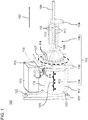
- Figure 1 schematically shows a perspective view of a first exemplary embodiment of a mechanical train, generally designated by reference numeral 100.
- the mechanical train 100 can be part of a drive train of a vehicle, for example a commercial vehicle.
- the mechanical train 100 comprises a housing 102 which is sealed to receive a lubricant.
- the housing 102 comprises one or more housing walls 104, 106 and 108, in the interior of which components 105, 107 and 109 of a mechanism are arranged and are in contact with the lubricant.
- the exemplary embodiment shown comprises the housing 102 a housing wall 104 of a crankshaft 105 of an internal combustion engine 110, a housing wall 106 of a flywheel 107 and a housing wall 108 of a transmission with shafts 109.
- Alternative exemplary embodiments include a partial combination, for example only the housing wall 108 of the transmission, or additional housing sections.
- Channels 112 for static or flowing absorption of a fluid are integrated in the housing walls 104, 106 and 108.
- the mechanism 105, 107, 109 for transmitting drive power defines a longitudinal direction 103.
- the channels 112 are, at least in sections 113, parallel to the longitudinal direction.
- the channels 112 are separated from the inner area of the housing 102 by the inside remaining wall thickness of the respective housing wall 104, 106 and 108, so that there is no mixing with the lubricant or influencing the lubrication of the mechanics 105, 107 or 109 in the housing 102.
- the housing walls 104, 106 and 108 are preferably made of cast iron, in particular cast steel.
- the channels 112 are introduced as cast channels, for example in the housing wall 108 of the transmission.
- a fluid within the vehicle can communicate or flow along the drive train 100 without additional space requirements.
- a pressure accumulator can be formed by the cavity of the channels 112. The fluid is through channels 112 branchable along the mechanical line and / or is in heat exchange with the mechanical system.
- the channels 112 can stiffen the housing 102, for example with the same or reduced mass of the housing walls 104, 106 or 108. As an alternative or in addition, the channels 112 can run in ribs or cast seams formed on the outside of the housing wall.
- the channels 112 are separated from the outside of the housing 102 by predetermined breaking points. For example, at the predetermined breaking points, a wall of the channels 112 to the surface of the housing walls 104, 106 or 108 is reduced.
- the outside wall of the channels 112 or the surface of the housing wall 104, 106 or 108 along the channels 112 is also referred to as the outer skin of the channels 112.
- the outer skin of the channels 112 can break open the predetermined breaking point towards the outside if an excess pressure defined by the thickness of the outer skin is exceeded (for example when the fluid freezes). In this way, cracks in the housing wall 104, 106 or 108 to the interior of the housing 102, mixing of different fluids in adjacent channels 112 and / or mixing between the fluid in the channel 112 and the lubricant in the interior can be avoided.
- the fluid can be gaseous or liquid. Regardless of the physical state of the fluid, the fluid can be designed for control, power transmission and / or for heat exchange.
- the fluid can comprise a coolant for cooling the lubricant and / or the mechanics 105, 107 and / or 109 arranged in the housing 102.
- the channels 112 can be partially or completely in fluid communication with one another.
- a first subsystem of the channels 112 can receive a first fluid and a second subsystem of the channels 112 separate from the first subsystem can receive a second fluid.
- the first fluid can be gaseous.
- the second fluid can be liquid.
- the housing 102 comprises a plurality of housing walls (also referred to as a multi-unit gear housing 102 or modular system), for example the housing walls 104, 106 and 108, the housing walls 104, 106 or 108 have flange surfaces, for example for screw connection of the housing walls.
- Channels 112 which extend over a plurality of the housing walls 104, 106 and 108, comprise openings 114 in the respective flange surface, that in the case of flange surfaces which abut one another are in alignment to form a continuous channel 112 over the flange surface of the housing walls 104, 106 and 108.
- the channels 112 can be designed via a coupling flange of the housing wall 108 of the transmission to the housing wall 106 of the flywheel 107.
- the aligned openings 114 in the abutting flange surfaces are sealed off from other channels.
- cross connections can be formed between the channels 112.
- the openings 114 are arranged in the flange surfaces on a circle with a first diameter.
- the flange surfaces On a second circle with a larger diameter than that of the first circle, the flange surfaces have a circumferential groove for receiving an O-ring for sealing the flange surfaces lying against one another.
- a fold is formed on each of the abutting flange surfaces for the positive and pressure-tight connection of the adjacent housing walls (for example, housing walls 104 and 106 or housing walls 106 and 108).
- sections of the channels 112 which change the direction are incorporated into individual housing walls (for example in the housing wall 106 of the flywheel 107) and / or an intermediate module or terminating module which is connected to the housing wall 108 via flange surfaces.
- the channel 112 can run differently from the longitudinal direction.
- the channel 112 can be sectionally radial to the longitudinal direction (in particular upwards or downwards in the illustration of FIG Figure 1 ) run.
- connections 116 for flexible hose lines or pipes
- to the channels 112 can be arranged, for example, at convenient locations on the housing wall or the module.
- connection 116 for inlet and outlet are connected to an air compressor 118, for example.
- Compressed air stored in the channels 112 can be used to control a manual transmission of a commercial vehicle.
- one of the compressed air channels 112 branches off to a pneumatic control which is in fluid communication with the manual transmission.
- a part of the channels 112 in the housing wall 104 of the crankshaft 105 extends in the direction of an engine cooler 120. This allows the length of an exposed connecting path 122 to the engine cooler to be minimized. For example, cooling water circulates in this part of the channels 112 as the fluid.
- a heat exchanger 124 of an intarder or retarder is arranged on the output side 108 of the transmission.
- An oil-carrying brake circuit of the heat exchanger 124 is connected to the intarder or retarder.
- a cooling water-carrying cooling circuit of the heat exchanger 124 is connected to the engine cooling 120 or a separate fan via at least part of the channels 112.
- At least some of the channels 112 are connected to an air conditioning system, in particular a heater, of the vehicle.
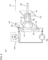
- the second exemplary embodiment shown schematically, connects the ducts 112 to a ventilated plate heat exchanger 126 and a circulation pump 128 for air heating.
- the fluid conveys the waste heat of the mechanics 105, 107 and / or 109 generated in the mechanical train 100 to the air conditioning system, for example to the plate heat exchanger 126, via the channels 112.
- Radial sections 130 in the housing wall 106 of the flywheel 107 connect the longitudinal sections of the channels 112 to connections 116 of the air conditioning system.
- the channels 112 can be designed for parallel flow (also: parallel connection) or for sequential flow (also: series connection).
- the channels 112 can be in fluid connection in pairs by means of a termination module 132 with a cross connection 134.
- a flow direction of the fluid can be reversed in the termination module 132, or by means of a cross connection within the housing wall 108.
- the direction of flow of the fluid is reversed several times.
- the fluid can flow through the housing wall 108 in a meandering manner for a particularly effective heat exchange with the mechanics arranged therein, for example the transmission.
- Figure 3 schematically shows an elevation of a third exemplary embodiment of a mechanical train 100 of a motor vehicle.
- Features that correspond functionally or structurally to a feature of the previous exemplary embodiments are provided with the same reference symbols.
- the modules and features shown here can also be arranged multiple times or in each sub-combination in the mechanical train 100, for example for a multiple reversal of the flow direction in the channels 112.
- a housing wall 108 of a transmission is connected to the housing wall 106 of a flywheel, optionally via an intermediate module 138.
- a housing wall of the intermediate module 138 comprises a plurality of through holes 115 parallel to the housing wall of the intermediate module and in spatial association with cross-connections 134 in the housing wall 106 or a first channel opening 136.
- the first channel opening 136 opens at an end face of the housing wall 106 opposite the intermediate module 138.
- Figure 4 schematically shows a sectional view of an exemplary embodiment of the flywheel housing wall 106 in a sectional plane parallel to the longitudinal direction 103.
- a second channel opening 137 is provided in the housing wall 106 on the end face (in which the first channel opening 136 also opens).
- the second channel opening 137 is laterally spaced (ie transverse to the longitudinal direction 103) from the first channel opening 136.
- the second channel opening 137 can be brought into fluid connection with a connection 116 via a through hole 115.
- the first channel opening 136 and the second channel opening 137 are in fluid communication via a flange 140.
- Figure 5 schematically shows a view of an exemplary embodiment of a flange surface of the flange 140 Figure 5 is designed to rest against the end face of the housing wall 106.
- the flange 140 is pressed onto the end face of the housing wall 106 via a plurality of flange screws 142.
- the first channel opening 136 and the second channel opening 137 closed in a fluid-tight manner via one or more seals to the outside area (outside the housing 102).
- the first channel opening 136 and the second channel opening 137 are separated from the inner region (inside the housing 102) by the housing wall 106 in a fluid-tight manner.
- the seal comprises an O-ring 146.
- the O-ring is arranged in a circumferential and closed groove in the end face of the housing wall 106.
- the O-ring 146 is pressed into the groove in a fluid-tight manner by a projection 147 corresponding to the circumferential and closed groove on the flange surface.
- a labyrinth seal is arranged on the flange surface.
- the labyrinth seal comprises one or more circumferential and closed recesses 144 in the end face of the housing wall 106 as well as circumferential and closed projections 145 (complementary to the recesses) on the flange surface of the flange 140.
- the options of one or more seals in the flange surface described above for the first channel opening 136 and the second channel opening 137 can be formed correspondingly for each channel opening 114 (and / or each through hole 115) on each flange surface.
- a circumferential O-ring seal and / or a circumferential labyrinth seal can be provided in the flange surface around individual or each of the channel openings 114 (and / or each through hole 115). This is advantageous, for example, if different fluids flow through the different channel openings 114 (and / or through holes 115) of a flange surface in order to prevent fluid exchange between the channels 112 on the flange surface.
- At least one seal surrounding the plurality for example an O-ring seal and / or labyrinth seal, can be located radially outside of all channel openings 114 (and / or through holes) in the flange surface 115) can be arranged.
- at least one seal for example an O-ring seal and / or labyrinth seal
- One or more seals encircling the plurality radially inside and / or outside can, for example, enable a greater density of the channels 112 (for example a smaller distance between the channels 112) in the housing wall, preferably if the same fluid flows in the channels 112.
- the one or more seals enclose a recess 148 in the flange 140 through which the first channel opening 136 and the second channel opening 137 are in fluid communication.
- a first (in Figure 5 Cross dimension shown in the vertical direction corresponds to the uniform diameter of the first channel opening 136 and the second channel opening 137.
- a second (in Figure 5 horizontally shown) transverse dimension of the recess 148 is enlarged compared to the first transverse dimension by the lateral distance between the first channel opening 136 and the second channel opening 137.
- Figure 6 schematically shows a cross section perpendicular to the longitudinal direction 103 through a fourth exemplary embodiment of the housing 102.
- a predetermined breaking point 150 can be implemented in any of the above-mentioned exemplary embodiments.
- the predetermined breaking point 150 is formed at individual points along the channel 112, continuously along one or more of the channel sections 113 in the longitudinal direction and / or continuously along one or more of the channel sections 130 in the radial direction.
- the channel 112 runs between an inner side 152 of the housing wall and an outer side 154 of the housing wall.
- the predetermined breaking point 150 is a local or (for example in cross section) global minimum of the remaining wall thickness between the channel 112 and the outside 154.
- the channel 112 is integrally formed in one piece with the housing wall (for example the housing wall 104, 106 and / or 108).
- An inner wall thickness 156 between the channel 112 and the inside 152 is preferably greater than an outer wall thickness 158 between the channel 112 and the outside 154.
- the predetermined breaking point 150 is formed, for example, by a notch in the outside 154 parallel to the channel 112.
- the outer wall thickness 158 at the predetermined breaking point 150 is reduced by 25% to 75%, for example by 50%.
Landscapes
- Engineering & Computer Science (AREA)
- General Engineering & Computer Science (AREA)
- Mechanical Engineering (AREA)
- Chemical & Material Sciences (AREA)
- Combustion & Propulsion (AREA)
- Physics & Mathematics (AREA)
- Thermal Sciences (AREA)
- General Details Of Gearings (AREA)
Description
- Die vorliegende Erfindung betrifft einen Mechanikstrang eines Fahrzeugantriebs. Insbesondere ist ein Mechanikstrang zur integrierten Druckspeicherung und/oder Leitungsführung eines Fluids beschrieben.
- Herkömmliche Gehäuse für Antriebsstrangkomponenten umfassen integrierte Wasserkühlungen. Beispielsweise beschreibt das Dokument
US 2009/0173185 A1 ein zylindrisches Gehäuse, in dem ein Getriebe eines Außenbordmotors angeordnet ist. In das Gehäuse sind wasserführende Kanäle zur Kühlung des Getriebes angeordnet. Auch das DokumentDE 196 41 052 A1 beschreibt einen Zylinderblock für einen V-Motor. Zwischen den Zylinderreihen des V-Motors ist ein Kühlmittelkanal angeordnet. - Das Dokument
US 2,487,215 A beschreibt ein Ölkühlungssystem für Brennkraftmaschinen, welches U-förmige Rohrleitungen umfasst, die innerhalb des Kurbelgehäuses der Brennkraftmaschine am Boden mit Klemmen befestigt sind. - Das Dokument
DE 100 58 110 A1 beschreibt ein Automatikgetriebe mit einer Kühlanordnung aus einem oder mehreren Wärmetauschern, die in das Getriebe integriert sind und Kühlkanäle senkrecht zu einer Getriebeachse umfassen kann. - Das Dokument
DE 196 25 357 A1 beschreibt einen Wärmetauscher, der in ein Getriebegehäuse seitlich integriert oder an der Unterseite angebaut ist und zwei Kühlschlangen umfasst, von denen die eine das Kühlmedium senkrecht zur Getriebeachse führt und die zweite das Arbeitsmedium eines Retarders führt und bei einem Bremsvorgang Wärme an die erste Kühlschlange abgibt. - Das Dokument
WO 03/006850 A1 - Herkömmlicherweise umfassen bei einem Kraftfahrzeug, insbesondere einem Nutzfahrzeug, pneumatische Systeme, hydraulische Systeme und Wärmetransportkreisläufe separate Leitungsführungen und Fluidspeicher. Aufgrund von Randbedingungen und begrenztem Bauraum ist es schwierig, die Leitungsführung zu minimieren und die Fluidspeicherung in direkter räumlicher Zuordnung zu funktionellen Systemkomponenten wie beispielsweise Kompressoren, Wärmetauschern, Aktuatoren oder Steuerventilen anzuordnen.
- Beispielsweise beschreibt das Dokument
DE 10 2013 201 789 A1 ein herkömmliches Kühlsystem für einen Intarder oder Retarder. Ein Wärmetauscher des Intarders bzw. Retarders ist über Kühlwasserleitungen mit einem Hauptkühler des Fahrzeugs und einem vom Kraftstoffverbrauch unabhängigen Zusatzkühler verbunden. - Jedoch führen fahrzeugweit vernetzte Fluidsysteme, beispielsweise zur Verbesserung der Energieeffizienz oder Betriebssicherheit, zu einer zunehmenden Komplexität der Leitungssysteme und Fluidspeicher, die durch den verfügbaren Bauraum begrenzt ist. Auch sind Wartung und Sichtkontrolle solcher Fluidsysteme durch ihre Komplexität und Unzugänglichkeit erschwert.
- Somit besteht die Aufgabe, die Speicherung und Leitungsführung von Fluiden in einem Fahrzeug platzsparender auszuführen. Eine alternative oder weitere Aufgabe ist, Fluidkreisläufe zumindest abschnittsweise wartungsfrei auszuführen.
- Diese Aufgabe oder Aufgaben werden durch einen Mechanikstrang eines Fahrzeugantriebs mit den Merkmalen des Hauptanspruchs gelöst. Vorteilhafte Ausführungen und Anwendungen sind Gegenstand der abhängigen Ansprüche und werden im Folgenden unter teilweiser Bezugnahme auf die Figuren näher erläutert.
- Gemäß einem ersten Aspekt ist ein Mechanikstrang zum Antrieb eines Fahrzeugs, insbesondere eines Nutzfahrzeugs, bereitgestellt. Der Mechanikstrang umfasst ein zur Aufnahme eines Schmierstoffs abgedichtetes Gehäuse mit mindestens einer Gehäusewand; eine im Gehäuse angeordnete und vom Schmierstoff benetzte Mechanik mit mindestens einer Welle zur Übertragung von Antriebsleistung in Längsrichtung; und eine Vielzahl an Kanälen zur Aufnahme eines Fluids, wobei zumindest Abschnitte der Kanäle innerhalb der Gehäusewand in Längsrichtung verlaufen und durch die Gehäusewand vom Schmierstoff getrennt sind.Die Kanäle stehen mit einem Wärmekreislauf in Fluidverbindung oder sind mit einem Wärmekreislauf in Fluidverbindung bringbar.
- Ausführungsbeispiele des Mechanikstrangs können Vorrichtungen zur Druckspeicherung und/oder zur Leitungsführung des Fluids ohne zusätzlichen Bauraum ergänzen oder vollständig oder teilweise ersetzen. Durch die Anordnung der Kanäle innerhalb der Gehäusewand können die Kanäle vor äußeren mechanischen und Witterungseinflüssen geschützt und zumindest abschnittsweise wartungsfrei sein.
- Eine Längsachse der mindestens einen Welle kann die Längsrichtung definieren. Ausführungsbeispiele des Mechanikstrangs können eine Leitungsführung des Fluids in die Längsrichtung und die Übertragung der Antriebsleistung in die Längsrichtung platzsparend und/oder wartungsfrei vereinen.
- Ein mit dem Mechanikstrang mechanisch gekoppeltes Modul kann über die Kanäle in Fluidverbindung stehen oder gebracht werden mit Fluidanschlüssen, Fluidquellen und/oder Fluidsenken, die in Längsrichtung vom Modul beabstandet sind, beispielsweise ohne zusätzlichen Bauraum für Fluidleitungen. Alternativ oder ergänzend können über den Mechanikstrang mechanisch gekoppelte Module über die Kanäle in Fluidaustausch stehen oder gebracht werden.
- Soweit nicht ausdrücklich anders bestimmt, können sich die Begriffe "Kanal" und "Kanäle" auf einen zusammenhängenden Kanalabschnitt bzw. mehrere Kanalabschnitte beziehen, die innerhalb der Gehäusewand angeordnet sind. Eine für den "Kanal" oder die "Kanäle" beschriebene Eigenschaft kann zumindest abschnittsweise vorliegen.
- Jeder der Kanäle kann jeweils durch die Gehäusewand vom Schmierstoff getrennt sein, beispielsweise indem eine zum Gehäuseinneren hin verbleibende Wandstärke der Gehäusewand den Kanal und das Gehäuseinnere trennt. Das Fluid im Kanal und der Schmierstoff können unvermischte und/oder verschiedene Fluide sein.
- Die Kanäle oder eine Teilmenge der Kanäle können miteinander in Fluidverbindung stehen. Das Gehäuseinnere und die Kanäle können jeweils ohne Fluidverbindung sein.
- Die Kanäle können nur durch die Gehäusewand vom Schmierstoff getrennt sein. Eine Wandung der Kanäle kann integral-einstückig mit der Gehäusewand sein. Die Kanäle können die einzigen Hohlräume in einer außerhalb der Kanäle massiven Gehäusewand sein.
- Das Fluid kann eine Flüssigkeit, ein Gas und/oder mehrere Phasen umfassen, beispielsweise als Dispersion. Das Fluid kann ein Arbeitsmedium sein, insbesondere zur Druckspeicherung, zum Wärmetransport und/oder zur hydraulischen Steuerung. Optional nimmt das Fluid entlang der Kanäle unterschiedliche Aggregatzustände an, beispielsweise mit einem flüssigen Abschnitt und einem gasförmigen Abschnitt.
- Die Kanäle können mit einem Überdrucksystem, einem Unterdrucksystem und/oder einem Hydrauliksystem in Fluidverbindung stehen oder bringbar sein. Die Kanäle können Teil eines Wärmekreislaufs, eines Überdrucksystems und/oder eines Hydrauliksystems sein. Durch die Kanäle kann sich der Wärmekreislauf, das Überdrucksystem und/oder das Hydrauliksystem in Längsrichtung erstrecken, beispielsweise ohne zusätzlichen Leitungsbauraum.
- Die Kanäle können mit einer Umwälzpumpe, einer Wärmequelle und/oder einer Wärmesenke verbunden sein. Die Umwälzpumpe kann eine Zirkulation des Fluids zwischen der Wärmequelle und der Wärmesenke über die Kanäle antreiben.
- Das Fluid kann ein Wärmeträger sein, beispielsweise ein Kühlmittel (auch: Kühlmedium) oder ein Heizmittel (auch: Heizmedium). Die Wärmeleitfähigkeit des Fluids kann mindestens 0,5 W/(m . K) sein. Alternativ oder ergänzend kann die spezifische Wärmekapazität des Fluids mindestens 5 kJ/(kg . K) sein.
- Die mit dem Fluid gefüllten Kanäle können ein Druckreservoir (insbesondere ein Überdruck- und/oder Unterdruckreservoir) bilden, beispielsweise ohne zusätzlichen Bauraum für einen separaten Druckspeicher. Beispielsweise können die Kanäle mit einem Druckluftkompressor und/oder einer Vakuumpumpe verbunden sein und/oder in Fluidverbindung mit einem Druckluftverbraucher des Fahrzeugs stehen.
- Alternativ oder ergänzend können die Kanäle dazu ausgebildet sein, mittels des Fluids Signale, Kräfte und/oder (hydraulische oder pneumatische) Energie in die Längsrichtung zu übertragen. Dazu können die Kanäle an zwei oder mehr (beispielsweise in Längsrichtung beabstandeten) Stellen jeweils mit einem Zylinder (beispielsweise einem Hydraulik- oder Pneumatik-Zylinder) verbunden sein.
- Die Kanäle können parallel zur Gehäusewand innerhalb der Gehäusewand angeordnet sein. Alternativ oder ergänzend können die Kanäle kreuzungsfrei innerhalb der Gehäusewand verlaufen. Beispielsweise können die Kanäle mäanderförmig in der Gehäusewand verlaufen.
- Mindestens ein weiterer Abschnitt der Kanäle kann innerhalb und/oder parallel der Gehäusewand quer zur Längsrichtung verlaufen. Beispielsweise kann mindestens ein weiterer Abschnitt der Kanäle innerhalb und/oder parallel der Gehäusewand senkrecht zur Längsrichtung verlaufen.
- Mindestens ein weiterer Abschnitt der Kanäle kann innerhalb und/oder parallel der Gehäusewand bogenförmig (beispielsweise auf einem Kreissegment) oder umlaufend (beispielsweise einfach umlaufend oder mehrfach spiralförmig umlaufend) um die mindestens eine Welle verlaufen. Alternativ oder ergänzend kann mindestens ein weiterer Abschnitt der Kanäle innerhalb und/oder parallel der Gehäusewand radial zur mindestens einen Welle verlaufen.
- Mindestens einer der Kanäle, beispielsweise ein zur Längsrichtung quer verlaufender Abschnitt, kann in einen Anschluss münden. Der Anschluss kann von außerhalb des Gehäuses zugänglich sein.
- Zwei oder mehr der Kanäle, beispielsweise innerhalb derselben Gehäusewand, können vom selben Fluid in zueinander entgegengesetzten Richtungen durchströmt werden. An einem Ende des Mechanikstrangs kann ein Modul angeordnet oder anordenbar sein, das die Kanäle verbindet (beispielsweise paarweise verbindet) für eine Umkehr der Strömungsrichtung im Modul.
- An einem ersten Ende des Mechanikstrangs kann ein erstes Modul angeordnet sein. An einem in Längsrichtung gegenüberliegenden zweiten Ende des Mechanikstrangs kann ein zweites Modul angeordnet sein. Das erste Modul und das zweite Modul können über die Kanäle in Fluidverbindung stehen oder bringbar sein.
- Beispielsweise können die Module dazu ausgebildet sein, das Fluid durch die Kanäle zwischen dem ersten Modul und dem zweiten Modul zu zirkulieren. Alternativ oder ergänzend weicht ein Verlauf der Kanäle in mindestens einem der Module von der Längsrichtung ab und/oder mündet in einen Fluidanschluss.
- Die Kanäle können zur Übertragung hydraulischer Kräfte mittels des Fluids ausgebildet sein. Die Kanäle können beispielsweise am ersten Ende mit einem Bremskraftverstärker und am zweiten Ende mit mindestens einem Bremszylinder in Fluidverbindung stehen.
- Das erste Modul und das zweite Modul können in Längsrichtung durch den Mechanikstrang räumlich getrennt sein. Das erste Modul und das zweite Modul können jeweils mit der Mechanik des Mechanikstrangs in Wirkverbindung stehen, beispielsweise jeweils mit einer Welle der Mechanik gekoppelt sein.
- Das erste Modul kann einen Kompressor, beispielsweise für Druckluft (auch: Luftpresser), oder eine Abzweigung zu einem Kompressor umfassen. Das Fluid kann Druckluft sein. Der Kompressor kann am ersten Ende von einem Fahrzeugmotor, beispielsweise einer Brennkraftmaschine, angetrieben sein. Das zweite Modul kann einen Druckluftverbraucher oder eine Abzweigung oder einen Anschluss zu einem Druckluftverbraucher umfassen. Der Druckluftverbraucher kann ein Schaltgetriebe, eine Kupplung und/oder eine Einheit mit Schaltgetriebe und Kupplung sein.
- Alternativ oder ergänzend kann das erste Modul einen Kühler, Kühlkreislauf oder eine Abzweigung oder einen Anschluss zu einem Kühler umfassen. Der Kühler kann ein Motorkühler oder Frontkühler des Fahrzeugs sein. Das Fluid kann Kühlwasser sein. Das zweite Modul kann einen Wärmetauscher oder eine Abzweigung oder einen Anschluss zu einem Wärmetauscher umfassen. Beispielsweise umfasst das zweite Modul eine Dauerbremse und/oder eine Sekundärbremse mit dem Wärmetauscher. Die Dauerbremse kann ausgangsseitig am Getriebe angekoppelt sein. Die Dauerbremse kann ein Retarder, ein Intarder oder eine Wirbelstrombremse sein. Ein Ölkreislauf der Dauerbremse oder der Sekundärbremse kann im Wärmetauscher mit dem Kühlwasser in Wärmeaustausch stehen oder bringbar sein.
- Das Gehäuse kann metallisch sein. Die Gehäusewand kann ein Metallguss sein. Die Kanäle können integral-einstückig mit der Gehäusewand gegossen sein.
- Die Mechanik kann eine Kurbelwelle einer Brennkraftmaschine, ein Schwungrad, eine Kupplung, ein Getriebe, eine Dauerbremse, eine elektrische Maschine und/oder einen Nebenabtrieb umfassen.
- Die Kanäle können in Fluidverbindung mit einer Klimaanlage, beispielsweise einer Heizung, des Fahrzeugs stehen oder bringbar sein. Die Kanäle können mit einem Kühler und/oder einer Fahrzeugheizung verbunden sein. Die Kanäle können in der Gehäusewand in Wärmeaustausch mit der Mechanik stehen. Eine Abwärme der Mechanik und/oder der Brennkraftmaschine kann über den Kühler an die Fahrzeugumgebung und/oder über die Fahrzeugheizung in das Innere des Fahrzeugs abgegeben werden.
- Alternativ oder ergänzend können die Kanäle die Wärmeleitfähigkeit und/oder die Masse der Gehäusewand gegenüber einer massiven Gehäusewand verringern, beispielsweise zur Wärmeisolation der Mechanik. Die Wärmeleitfähigkeit der Gehäusewand, beispielsweise senkrecht zur Gehäusewand und/oder quer zu den Kanälen, kann durch die Kanäle innerhalb der Gehäusewand weniger als die Hälfte der Wärmeleitfähigkeit einer vergleichbaren massiven Wand sein. Beispielsweise kann eine Wärmeleitfähigkeit der Gehäusewand höchstens halb so groß sein wie die Wärmeleitfähigkeit einer massiven Wand aus dem gleichen Material und mit der gleichen Wanddicke wie die Gehäusewand.
- Die Kanäle können das Gehäuse mechanisch versteifen. Eine Steifigkeit, beispielsweise eine Biegesteifigkeit, der Gehäusewand mit den Kanälen kann größer sein als eine Steifigkeit, beispielsweise eine Biegesteifigkeit, einer massiven Wand aus dem gleichen Material und mit der gleichen Masse wie die Gehäusewand.
- Alternativ oder ergänzend können an einer Außenfläche der Gehäusewand Rippen angeformt sein. Die Rippen können integral-einstückig mit der Gehäusewand sein. Die Kanäle, oder eine Teilmenge der Kanäle, können innerhalb und/oder entlang der Rippen verlaufen.
- Eine Außenfläche der Gehäusewand umfasst Sollbruchstellen. Die Sollbruchstellen sind dazu ausgebildet, bei einem Druck in den Kanälen, der größer als eine vorbestimmte Druckschwelle ist, die Kanäle oder den betreffenden Kanal an der Sollbruchstelle mit dem Äußeren der Gehäusewand in Fluidverbindung zu bringen. Eine äußere Wanddicke zwischen den Kanälen und der äußeren Oberfläche (auch: Außenfläche) der Gehäusewand kann kleiner sein als eine innere Wanddicke zwischen den Kanälen und der innenseitigen Oberfläche (auch: Innenfläche) der Gehäusewand. Dadurch kann eine Bruchrichtung bei Überdruck vorbestimmt sein. Die äußere Wanddicke kann (beispielsweise abhängig von einer Fließgrenze des Materials der Gehäusewand) durch die vorbestimmte Druckschwelle bestimmt sein.
- Das Gehäuse kann zwei oder mehr Gehäusewände umfassen. Die Kanäle, oder eine Teilmenge der Kanäle, können sich über zwei oder mehr Gehäusewände in Längsrichtung erstrecken. Die Gehäusewände können in Längsrichtung an Flanschflächen miteinander verbunden, beispielsweise verschraubt, sein. Die Kanäle können jeweils über Öffnungen in der Flanschfläche in Fluidverbindung stehen. Die Öffnungen eines jeden Kanals (der sich über die Gehäusewände hinweg erstreckt) können an den anliegenden Flanschflächen paarweise zur Deckung kommen. Die Kanäle können jeweils an anliegenden Flanschflächen fluchten. An der Flanschfläche können die Kanäle jeweils zu benachbarten Kanälen, dem Inneren des Gehäuses, und/oder dem Äußeren des Gehäuses abgedichtet sein.
- Die Erfindung betrifft ferner die Verwendung eines Mechanikstrangs gemäß dem vorstehenden Aspekt zur Druckspeicherung und/oder zur Leitungsführung eines Fluids in einem Fahrzeug.
- Gemäß einem weiteren Aspekt ist ein Kraftfahrzeug, vorzugsweise ein Nutzfahrzeug, mit einem Mechanikstrang gemäß dem erstgenannten Aspekt bereitgestellt.
- Die zuvor beschriebenen bevorzugten Ausführungsformen und Merkmale der Erfindung sind beliebig miteinander kombinierbar. Weitere Einzelheiten und Vorteile der Erfindung werden im Folgenden unter Bezugnahme auf die beigefügten Zeichnungen beschrieben. Es zeigen:
- Figur 1
- schematisch eine perspektivische Darstellung eines ersten Ausführungsbeispiels eines Mechanikstrangs eines Fahrzeugantriebs;
- Figur 2
- schematisch eine perspektivische Darstellung eines zweiten Ausführungsbeispiels eines Mechanikstrangs eines Fahrzeugantriebs;
- Figur 3
- schematisch einen Aufriss eines dritten Ausführungsbeispiels eines Mechanikstrangs eines Fahrzeugantriebs;
- Figur 4
- schematisch eine Schnittdarstellung eines Gehäuses in einer Ebene parallel einer Längsrichtung;
- Figur 5
- schematisch eine Ansicht einer Flanschfläche; und
- Figur 6
- schematisch eine Schnittdarstellung einer Gehäusewand in einer Ebene senkrecht zur Längsrichtung.
-
Figur 1 zeigt schematisch eine perspektivische Darstellung eines ersten Ausführungsbeispiels eines allgemein mit dem Bezugszeichen 100 bezeichneten Mechanikstrangs. Der Mechanikstrang 100 kann Teil eines Antriebsstrangs eines Fahrzeugs, beispielsweise eines Nutzfahrzeugs, sein. - Der Mechanikstrang 100 umfasst ein Gehäuse 102, das zur Aufnahme eines Schmierstoffs abgedichtet ist. Das Gehäuse 102 umfasst eine oder mehrere Gehäusewände 104, 106 und 108, in deren Innenbereich jeweils Komponenten 105, 107 und 109 einer Mechanik angeordnet und in Kontakt mit dem Schmierstoff stehen.
- Im in
Figur 1 gezeigten Ausführungsbeispiel umfasst das Gehäuse 102 eine Gehäusewand 104 einer Kurbelwelle 105 einer Brennkraftmaschine 110, eine Gehäusewand 106 eines Schwungrads 107 und eine Gehäusewand 108 eines Getriebes mit Wellen 109. Alternative Ausführungsbeispiele umfassen eine Teilkombination, beispielsweise nur die Gehäusewand 108 des Getriebes, oder zusätzliche Gehäuseabschnitte. - In die Gehäusewände 104, 106 und 108 sind Kanäle 112 zur statischen oder strömenden Aufnahme eines Fluids integriert. Die Mechanik 105, 107, 109 zur Übertragung von Antriebsleistung definiert eine Längsrichtung 103. Die Kanäle 112 sind, zumindest in Abschnitten 113, parallel zur Längsrichtung.
- Die Kanäle 112 sind vom Innenbereich des Gehäuses 102 durch die innenseitige Restwanddicke der jeweilige Gehäusewand 104, 106 und 108 getrennt, so dass es zu keiner Vermischung mit dem Schmierstoff oder Beeinflussung der Schmierung der Mechanik 105, 107 bzw. 109 im Gehäuse 102 kommt.
- Die Gehäusewände 104, 106 und 108 sind vorzugsweise aus Guss, insbesondere Stahlguss, gefertigt. Die Kanäle 112 sind, beispielsweise in der Gehäusewand 108 des Getriebes, als Gusskanäle eingebracht.
- Indem die Kanäle 112 in die Gehäusewände 104, 106 und 108 integriert sind, kann ohne zusätzliche Bauraumanforderungen darin ein Fluid innerhalb des Fahrzeugs entlang des Antriebsstrangs 100 kommunizieren oder strömen. Alternativ oder ergänzend kann durch den Hohlraum der Kanäle 112 ein Druckspeicher gebildet sein. Das Fluid ist durch die Kanäle 112 entlang des Mechanikstrangs abzweigbar und/oder steht in Wärmeaustausch mit der Mechanik.
- Die Kanäle 112 können, beispielsweise bei gleicher oder reduzierter Masse der Gehäusewände 104, 106 oder 108, das Gehäuse 102 versteifen. Alternativ oder ergänzend können die Kanäle 112 in an der Außenseite der Gehäusewand angeformten Rippen oder Gussnähten verlaufen.
- Die Kanäle sind 112 zur Umgebung des Gehäuses 102 nach außen durch Sollbruchstellen getrennt. Beispielsweise ist an den Sollbruchstellen eine Wandung der Kanäle 112 zur Oberfläche der Gehäusewände 104, 106 oder 108 reduziert. Die außenseitige Wandung der Kanäle 112 oder die Oberfläche der Gehäusewand 104, 106 oder 108 entlang der Kanäle 112 wird auch als Außenhaut der Kanäle 112 bezeichnet. Die Außenhaut der Kanäle 112 kann bei Überschreiten eines durch die Stärke der Außenhaut definierten Überdrucks (beispielsweise beim Gefrieren des Fluids) die Sollbruchstelle nach außen hin aufbrechen. So können Risse in der Gehäusewand 104, 106 oder 108 zum Innenbereich des Gehäuses 102, ein Vermischen unterschiedlicher Fluide in benachbarten Kanälen 112 und/oder ein Vermischen zwischen dem Fluid im Kanal 112 und dem Schmierstoff im Innenbereich vermieden werden.
- Das Fluid kann gasförmig oder flüssig sein. Unabhängig vom Aggregatzustand des Fluids kann das Fluid zur Steuerung, Kraftübertragung und/oder zum Wärmeaustausch ausgebildet sein. Beispielsweise kann das Fluid ein Kühlmittel umfassen zur Kühlung des Schmierstoffs und/oder der im Gehäuse 102 angeordneten Mechanik 105, 107 und/oder 109.
- Die Kanäle 112 können teilweise oder vollständig untereinander in Fluidverbindung stehen. Beispielsweise kann ein erstes Teilsystem der Kanäle 112 ein erstes Fluid und ein vom ersten Teilsystem getrenntes zweites Teilsystem der Kanäle 112 ein zweites Fluid aufnehmen. Das erste Fluid kann gasförmig sein. Das zweite Fluid kann flüssig sein.
- Soweit das Gehäuse 102 mehrere Gehäusewände umfasst (auch als mehrgliedriges Getriebegehäuse 102 oder Baukastensystem bezeichnet), beispielsweise die Gehäusewände 104, 106 und 108, weisen die Gehäusewände 104, 106 oder 108 Flanschflächen auf, beispielsweise zur Schraubverbindung der Gehäusewände.
- Kanäle 112, die sich über mehrere der Gehäusewände 104, 106 und 108 erstrecken, umfassen Öffnungen 114 in der jeweiligen Flanschfläche, die bei aneinander anliegenden Flanschflächen in Flucht stehen zur Ausbildung eines durchgehenden Kanals 112 über die Flanschfläche der Gehäusewände 104, 106 und 108 hinweg. Beispielsweise können die Kanäle 112 über einen Kupplungsflansch der Gehäusewand 108 des Getriebes hinaus zur Gehäusewand 106 des Schwungrads 107 ausgeführt sein.
- Dabei sind die fluchtenden Öffnungen 114 in den aneinander anliegenden Flanschflächen zu anderen Kanälen hin abgedichtet. Alternativ oder ergänzend können Querverbindungen zwischen den Kanälen 112 ausgebildet sein.
- In einer ersten Variante sind die Öffnungen 114 in den Flanschflächen auf einem Kreis mit einem ersten Durchmesser angeordnet. Die Flanschflächen weisen auf einem zweiten Kreis mit größerem Durchmesser als der des ersten Kreises eine umlaufende Nut zur Aufnahme eines O-Rings zur Abdichtung der aneinander anliegenden Flanschflächen auf.
- In einer zweiten Variante ist an den aneinander anliegenden Flanschflächen jeweils ein Falz angeformt zur formschlüssigen und druckdichten Verbindung der benachbarten Gehäusewände (beispielsweise der Gehäusewände 104 und 106 oder der Gehäusewände 106 und 108).
- Alternativ oder ergänzend sind in einzelnen Gehäusewänden (beispielsweise in der Gehäusewand 106 des Schwungrads 107) und/oder einem Zwischenmodul oder Abschlussmodul, das über Flanschflächen mit der Gehäusewand 108 verbunden ist, richtungsändernde Abschnitte der Kanäle 112 eingearbeitet. Beispielsweise kann beim Übergang von einer Gehäusewand mit einer ersten Querabmessung zu einer Gehäusewand oder einem Modul mit einer größeren zweiten Querabmessung der Kanal 112 abweichend von der Längsrichtung verlaufen. Beispielsweise kann der Kanal 112 abschnittsweise radial zur Längsrichtung (insbesondere nach oben oder nach unten in der Darstellung der
Figur 1 ) verlaufen. Dadurch können beispielsweise Anschlüsse 116 (für flexible Schlauchleitungen oder Rohre) zu den Kanälen 112 an zugangsgünstigen Stellen der Gehäusewand oder des Moduls angeordnet sein. - In dem in
Figur 1 gezeigten Ausführungsbeispiel ist in einem massiven Abschnitt der Gehäusewand 106 des Schwungrads 107 ein Durchgangsloch 115, das den Kanal 112 mit einem Anschluss 116 verbindet. Anschlüsse 116 für Zu- und Ablauf sind beispielsweise mit einem Luftpresser 118 verbunden. - Eine in den Kanälen 112 bevorratete Druckluft kann zur Steuerung eines Schaltgetriebes eines Nutzfahrzeuges eingesetzt werden. Dazu zweigt einer der druckluftführenden Kanäle 112 zu einer pneumatischen Steuerung ab, die in Fluidverbindung mit dem Schaltgetriebe steht.
- Alternativ oder ergänzend zum Anschluss des Luftpressers 118 erstreckt sich ein Teil der Kanäle 112 in der Gehäusewand 104 der Kurbelwelle 105 in Richtung eines Motorkühlers 120. Dadurch kann die Länge einer freiliegenden Verbindungsstrecke 122 zum Motorkühler minimiert werden. Beispielsweise zirkuliert in diesem Teil der Kanäle 112 Kühlwasser als das Fluid.
- In einer dritten Variante, die mit jeder der vorstehenden Varianten kombinierbar ist, ist an der Ausgangsseite 108 des Getriebes ein Wärmetauscher 124 eines Intarders oder Retarders angeordnet. Ein ölführender Bremskreislauf des Wärmetauschers 124 ist mit dem Intarder bzw. Retarder verbunden. Ein kühlwasserführender Kühlkreislauf des Wärmetauschers 124 ist über zumindest einen Teil der Kanäle 112 mit der Motorkühlung 120 oder einem separaten Lüfter verbunden.
- In einer vierten Variante, die mit jeder der vorstehenden Varianten kombinierbar ist, ist zumindest ein Teil der Kanäle 112 mit einer Klimaanlage, insbesondere einer Heizung, des Fahrzeugs verbunden.
- In dem in
Figur 2 schematisch gezeigten zweiten Ausführungsbeispiel sind die Kanäle 112 mit einem belüfteten Plattenwärmetauscher 126 und einer Umwälzpumpe 128 zur Luftbeheizung verbunden. Das Fluid fördert über die Kanäle 112 die im Mechanikstrang 100 entstehende Abwärme der Mechanik 105, 107 und/oder 109 zur Klimaanlage, beispielsweise zum Plattenwärmetauscher 126. - Radiale Abschnitte 130 in die Gehäusewand 106 des Schwungrads 107 verbinden die in Längsrichtung verlaufenden Abschnitte der Kanäle 112 mit Anschlüssen 116 der Klimaanlage.
- In jedem hierin genannten Ausführungsbeispiel oder Variante können die Kanäle 112 zur parallelen Durchströmung (auch: Parallelschaltung) oder zur sequentiellen Durchströmung (auch: Reihenschaltung) ausgebildet sein. Insbesondere können die Kanäle 112 durch ein Abschlussmodul 132 mit einer Querverbindung 134 paarweise in Fluidverbindung stehen. Im Abschlussmodul 132, oder durch eine Querverbindung innerhalb der Gehäusewand 108, kann eine Strömungsrichtung des Fluids umgekehrt werden.
- In einer Ausgestaltung wird die Strömungsrichtung des Fluids mehrfach umgekehrt. Beispielsweise kann das Fluid die Gehäusewand 108 mäanderartig durchströmen für einen besonders wirksamen Wärmeaustausch mit der darin angeordneten Mechanik, beispielsweise dem Getriebe.
-
Figur 3 zeigt schematisch einen Aufriss eines dritten Ausführungsbeispiels eines Mechanikstrangs 100 eines Kraftfahrzeugs. Merkmale, die funktional oder strukturell einem Merkmal der vorherigen Ausführungsbeispiele entsprechen, sind mit gleichen Bezugszeichen versehen. Die hierbei gezeigten Module und Merkmale können auch mehrfach oder in jeder Unterkombination im Mechanikstrangs 100 angeordnet sein, beispielsweise für eine mehrfache Umkehrung der Strömungsrichtung in den Kanälen 112. - Eine Gehäusewand 108 eines Getriebes ist, optional über ein Zwischenmodul 138, mit der Gehäusewand 106 eines Schwungrads verbunden. Eine Gehäusewand des Zwischenmoduls 138 umfasst eine Vielzahl an Durchgangslöchern 115 parallel zur Gehäusewand des Zwischenmoduls und in räumlicher Zuordnung zu Querverbindungen 134 in der Gehäusewand 106 bzw. einer ersten Kanalöffnung 136. Die erste Kanalöffnung 136 mündet an einer dem Zwischenmodul 138 gegenüberliegenden Stirnfläche der Gehäusewand 106.
-
Figur 4 zeigt schematisch eine Schnittdarstellung eines Ausführungsbeispiels der Schwungradgehäusewand 106 in einer Schnittebene parallel zu der Längsrichtung 103. In der Gehäusewand 106 an der Stirnfläche (in der auch die erste Kanalöffnung 136 mündet) ist eine zweite Kanalöffnung 137 vorgesehen. Die zweite Kanalöffnung 137 ist von der ersten Kanalöffnung 136 seitlich (d. h. quer zur Längsrichtung 103) beabstandet. - Die zweite Kanalöffnung 137 ist über ein Durchgangsloch 115 mit einem Anschluss 116 in Fluidverbindung bringbar. Die erste Kanalöffnung 136 und die zweite Kanalöffnung 137 stehen über einen Flansch 140 in Fluidverbindung.
-
Figur 5 zeigt schematisch eine Ansicht eines Ausführungsbeispiels einer Flanschfläche des Flansches 140. Die Flanschfläche derFigur 5 ist zur Anlage an der Stirnfläche der Gehäusewand 106 ausgebildet. - Der Flansch 140 ist über mehrere Flanschschrauben 142 an der Stirnfläche der Gehäusewand 106 angepresst. Dabei werden die erste Kanalöffnung 136 und die zweite Kanalöffnung 137 über eine oder mehrere Dichtungen zum Außenbereich (außerhalb des Gehäuses 102) fluiddicht verschlossen. Vom Innenbereich (innerhalb des Gehäuses 102) sind die erste Kanalöffnung 136 und die zweite Kanalöffnung 137 durch die Gehäusewand 106 fluiddicht separiert.
- Im in den
Figuren 4 und 5 gezeigten Ausführungsbeispiel umfasst die Dichtung einen O-Ring 146. Der O-Ring ist in einer umlaufenden und geschlossenen Nut in der Stirnfläche der Gehäusewand 106 angeordnet. Der O-Ring 146 wird durch eine der umlaufenden und geschlossenen Nut entsprechende Auskragung 147 an der Flanschfläche fluiddicht in die Nut gepresst. - Alternativ oder ergänzend (beispielsweise innerhalb des vom O-Ring 146 umschlossenen Bereichs) ist an der Flanschfläche eine Labyrinthdichtung angeordnet. Die Labyrinthdichtung umfasst eine oder mehre umlaufende und geschlossene Aussparungen 144 in der Stirnfläche der Gehäusewand 106 sowie (zu den Aussparungen komplementäre) umlaufende und geschlossene Auskragungen 145 an der Flanschfläche des Flansches 140.
- Die vorstehend für die erste Kanalöffnung 136 und die zweite Kanalöffnung 137 beschriebenen Optionen einer oder mehrerer Dichtungen in der Flanschfläche können entsprechend für jede Kanalöffnung 114 (und/oder jedes Durchgangsloch 115) an jeder Flanschfläche ausgebildet sein. Beispielsweise kann in der Flanschfläche um einzelne oder jede der Kanalöffnungen 114 (und/oder jedes Durchgangsloch 115) jeweils eine umlaufende O-Ring-Dichtung und/oder eine umlaufende Labyrinthdichtung vorgesehen sein. Dies ist beispielsweise vorteilhaft, falls durch die verschiedenen Kanalöffnungen 114 (und/oder Durchgangslöcher 115) einer Flanschfläche unterschiedliche Fluide strömen, um einen Fluidaustausch zwischen den Kanälen 112 an der Flanschfläche zu verhindern.
- Ferner kann bei einer Mehrzahl an Kanalöffnungen 114 (und/oder Durchgangslöchern 115) in einer Flanschfläche mindestens eine die Mehrzahl umschließende Dichtung, beispielsweise eine O-Ring-Dichtung und/oder Labyrinthdichtung, in der Flanschfläche radial außerhalb aller Kanalöffnungen 114 (und/oder Durchgangslöcher 115) angeordnet sein. Alternativ oder ergänzend kann radial innerhalb aller Kanalöffnungen 114 (und/oder Durchgangslöcher 115) mindestens eine Dichtung (beispielsweise eine O-Ring-Dichtung und/oder Labyrinthdichtung) in der Flanschfläche vorgehsehen sein. Eine oder mehrere die Mehrzahl radial innerhalb und/oder außerhalb umlaufende Dichtungen können beispielsweise eine größere Dichte der Kanäle 112 (beispielsweise einen kleineren Abstand zwischen den Kanälen 112) in der Gehäusewand ermöglichen, vorzugsweise falls in den Kanälen 112 dasselbe Fluid strömt.
- Die eine oder mehreren Dichtungen umschließen eine Aussparung 148 im Flansch 140, durch welche die erste Kanalöffnung 136 und die zweite Kanalöffnung 137 in Fluidverbindung stehen. Ein erstes (in
Figur 5 in vertikaler Richtung dargestelltes) Quermaß entspricht dem einheitlichen Durchmesser der ersten Kanalöffnung 136 und der zweiten Kanalöffnung 137. Ein zweites (inFigur 5 horizontal dargestelltes) Quermaß der Aussparung 148 ist gegenüber dem ersten Quermaß um den seitlichen Abstand der ersten Kanalöffnung 136 und der zweiten Kanalöffnung 137 vergrößert. -
Figur 6 zeigt schematisch einen zur Längsrichtung 103 senkrechten Querschnitt durch ein viertes Ausführungsbeispiel des Gehäuses 102. Merkmale, die funktional oder strukturell denen eines der vorherigen Ausführungsbeispiele entsprechen, sind mit übereinstimmenden Bezugszeichen versehen. Die in derFigur 6 dargestellte Implementierung einer Sollbruchstelle 150 kann in jedem der vorstehend genannten Ausführungsbeispiele implementiert werden. Beispielsweise ist die Sollbruchstelle 150 an einzelnen Stellen entlang des Kanals 112, durchgehend entlang eines oder mehrerer der Kanalabschnitte 113 in Längsrichtung und/oder durchgehend entlang eines oder mehrerer der Kanalabschnitte 130 in radialer Richtung ausgebildet. - Der Kanal 112 verläuft zwischen einer Innenseite 152 der Gehäusewand und einer Außenseite 154 der Gehäusewand. Die Sollbruchstelle 150 ist ein lokales oder (beispielsweise im Querschnitt) globales Minimum der verbleibenden Wandstärke zwischen dem Kanal 112 und der Außenseite 154. Der Kanal 112 ist mit der Gehäusewand (beispielsweise der Gehäusewand 104, 106 und/oder 108) integral-einstückig ausgebildet.
- Vorzugsweise ist eine Innenwandstärke 156 zwischen dem Kanal 112 und der Innenseite 152 größer als eine Außenwandstärke 158 zwischen dem Kanal 112 und der Außenseite 154. Die Sollbruchstelle 150 ist beispielsweise durch eine zum Kanal 112 parallele Kerbe in der Außenseite 154 gebildet. Beispielsweise ist an der Sollbruchstelle 150 die Außenwandstärke 158 um 25 % bis 75 %, beispielsweise um 50 %, verringert.
- Obwohl die Erfindung unter Bezugnahme auf bestimmte Ausführungsbeispiele beschrieben worden ist, ist es für einen Fachmann ersichtlich, dass verschiedene Änderungen vorgenommen werden können und Äquivalente als Ersatz verwendet werden können. Ferner können viele Modifikationen vorgenommen werden, um eine bestimmte Situation oder ein bestimmtes Material an die Lehre der Erfindung anzupassen. Folglich ist die Erfindung nicht auf die offenbarten Ausführungsbeispiele beschränkt, sondern umfasst alle Ausführungsbeispiele, die in den Bereich der beigefügten Patentansprüche fallen.
-
- 100
- Mechanikstrang eines Fahrzeugantriebs
- 102
- Gehäuse des Mechanikstrangs
- 103
- Längsrichtung
- 104
- Gehäusewand der Kurbelwelle
- 105
- Kurbelwelle
- 106
- Gehäusewand des Schwungrads
- 107
- Schwungrad
- 108
- Gehäusewand des Getriebes
- 109
- Getriebewellen
- 110
- Brennkraftmaschine
- 112
- Kanäle
- 113
- Kanalabschnitt parallel zur Längsrichtung
- 114
- Kanalöffnung in den Flanschflächen
- 115
- Durchgangsloch
- 116
- Anschluss
- 118
- Luftpresser
- 120
- Motorkühler
- 122
- Anschlussstrecke
- 124
- Wärmetauscher
- 126
- Plattenwärmtauscher einer Klimaanlage
- 128
- Umwälzpumpe
- 130
- Kanalabschnitt radial zur Längsrichtung
- 132
- Abschlussmodul
- 134
- Querverbindung
- 136
- Erste Kanalöffnung
- 137
- Zweite Kanalöffnung
- 138
- Zwischenmodul
- 140
- Flansch
- 142
- Flanschschrauben
- 144
- Aussparungen einer Labyrinthdichtung
- 145
- Auskragungen der Labyrinthdichtung
- 146
- O-Ring
- 147
- Auskragung zur O-Ringdichtung
- 148
- Aussparung
- 150
- Sollbruchstelle
- 152
- Innenseite
- 154
- Außenseite
- 156
- Innenwandstärke
- 158
- Außenwandstärke
Claims (15)
- Mechanikstrang (100) zum Antrieb eines Kraftfahrzeugs, insbesondere eines Nutzfahrzeugs, umfassend:ein zur Aufnahme eines Schmierstoffs abgedichtetes Gehäuse (102) mit mindestens einer Gehäusewand (104, 106, 108);eine im Gehäuse (102) angeordnete und vom Schmierstoff benetzte Mechanik (105, 107, 109) mit mindestens einer Welle zur Übertragung von Antriebsleistung in Längsrichtung; undeine Vielzahl an Kanälen (112) zur Aufnahme eines Fluids, wobei zumindest Abschnitte (113) der Kanäle (112) innerhalb der Gehäusewand (104, 106, 108) in Längsrichtung verlaufen und durch die Gehäusewand vom Schmierstoff getrennt sind, wobei die Kanäle (112) mit einem Wärmekreislauf in Fluidverbindung stehen oder bringbar sind,
gekennzeichnet durchSollbruchstellen in einer Außenfläche der Gehäusewand, die dazu ausgebildet sind, bei einem Druck des Fluids in den Kanälen (112), der größer als eine vorbestimmte Druckschwelle ist, die Kanäle mit dem Äußeren der Gehäusewand in Fluidverbindung zu bringen. - Mechanikstrang nach Anspruch 1, wobei die Kanäle (112) mit einem Überdrucksystem und/oder Unterdrucksystem und/oder einem Hydrauliksystem in Fluidverbindung stehen oder bringbar sind.
- Mechanikstrang nach Anspruch 1 oder 2, wobei das Fluid ein Wärmeträger ist und die Kanäle (112) in Fluidverbindung mit einer Klimaanlage des Kraftfahrzeugs stehen oder bringbar sind.
- Mechanikstrang nach einem der Ansprüche 1 bis 3, wobei das Fluid ein Heizmedium ist und die Kanäle (112) in Fluidverbindung mit einer Heizung des Kraftfahrzeugs stehen oder bringbar sind.
- Mechanikstrang nach einem der Ansprüche 1 bis 4, wobei die Kanäle (112) innerhalb der Gehäusewand parallel zur Gehäusewand (104, 106, 108) verlaufen.
- Mechanikstrang nach einem der Ansprüche 1 bis 5, wobei mindestens ein weiterer Abschnitt (130) der Kanäle (112) innerhalb der Gehäusewand (104, 106, 108) quer zur Längsrichtung verläuft.
- Mechanikstrang nach einem der Ansprüche 1 bis 6, wobei mindestens einer der Kanäle (112) in einen außerhalb des Gehäuses (102) zugänglichen Anschluss (116) mündet.
- Mechanikstrang nach einem der Ansprüche 1 bis 7, wobei an einem ersten Ende des Mechanikstrangs (100) ein erstes Modul und an einem dem ersten Ende in Längsrichtung gegenüberliegenden zweiten Ende des Mechanikstrangs ein zweites Modul angeordnet oder anordenbar ist, und wobei das erste Modul und das zweite Modul über die Kanäle (112) in Fluidverbindung stehen oder bringbar sind.
- Mechanikstrang nach Anspruch 8, wobei das erste Modul und/oder das zweite Modul am jeweiligen Ende mit der Mechanik des Mechanikstrangs (100) gekoppelt sind.
- Mechanikstrang nach Anspruch 8 oder 9, wobei das erste Modul einen Kühler (120) und das zweite Modul einen Wärmetauscher (124) umfasst.
- Mechanikstrang nach einem der Ansprüche 1 bis 10, wobei die Mechanik eine Kurbelwelle (105) einer Brennkraftmaschine (110), ein Schwungrad (107), eine Kupplung, ein Getriebe (109), eine Dauerbremse und/oder eine elektrische Maschine und/oder einen Nebenabtrieb umfasst.
- Mechanikstrang nach einem der Ansprüche 1 bis 11, wobei eine Wärmeleitfähigkeit der Gehäusewand (104, 106, 108) mit den Kanälen (112) höchstens halb so groß ist wie die Wärmeleitfähigkeit einer massiven Wand gleichen Materials und gleicher Wanddicke wie die Gehäusewand (104, 106, 108).
- Mechanikstrang nach einem der Ansprüche 1 bis 12, wobei eine Steifigkeit der Gehäusewand (104, 106, 108) mit den Kanälen (112) größer ist als eine Steifigkeit einer massiven Wand gleichen Materials und gleicher Masse wie die Gehäusewand (104, 106, 108).
- Mechanikstrang nach einem der Ansprüche 1 bis 13, wobei sich die Kanäle (112) über zwei oder mehr Gehäusewände (104, 106, 108) in Längsrichtung erstrecken, die Gehäusewände (104, 106, 108) in Längsrichtung an Flanschflächen miteinander verbunden sind, und die Kanäle (112) jeweils über Öffnungen in der Flanschfläche in Fluidverbindung stehen.
- Kraftfahrzeug, insbesondere Nutzfahrzeug, mit einem Antriebstrang, der einen Mechanikstrang (100) gemäß einem der Ansprüche 1 bis 14 umfasst.
Applications Claiming Priority (2)
| Application Number | Priority Date | Filing Date | Title |
|---|---|---|---|
| DE102016009019.7A DE102016009019A1 (de) | 2016-07-23 | 2016-07-23 | Mechanikstrang eines Fahrzeugantriebs |
| EP17180641.7A EP3273018B1 (de) | 2016-07-23 | 2017-07-11 | Mechanikstrang eines fahrzeugantriebs |
Related Parent Applications (2)
| Application Number | Title | Priority Date | Filing Date |
|---|---|---|---|
| EP17180641.7A Division-Into EP3273018B1 (de) | 2016-07-23 | 2017-07-11 | Mechanikstrang eines fahrzeugantriebs |
| EP17180641.7A Division EP3273018B1 (de) | 2016-07-23 | 2017-07-11 | Mechanikstrang eines fahrzeugantriebs |
Publications (2)
| Publication Number | Publication Date |
|---|---|
| EP3444453A1 EP3444453A1 (de) | 2019-02-20 |
| EP3444453B1 true EP3444453B1 (de) | 2020-02-19 |
Family
ID=59337481
Family Applications (3)
| Application Number | Title | Priority Date | Filing Date |
|---|---|---|---|
| EP18197494.0A Active EP3444453B1 (de) | 2016-07-23 | 2017-07-11 | Mechanikstrang eines fahrzeugantriebs |
| EP19178504.7A Active EP3557014B1 (de) | 2016-07-23 | 2017-07-11 | Mechanikstrang eines fahrzeugantriebs |
| EP17180641.7A Active EP3273018B1 (de) | 2016-07-23 | 2017-07-11 | Mechanikstrang eines fahrzeugantriebs |
Family Applications After (2)
| Application Number | Title | Priority Date | Filing Date |
|---|---|---|---|
| EP19178504.7A Active EP3557014B1 (de) | 2016-07-23 | 2017-07-11 | Mechanikstrang eines fahrzeugantriebs |
| EP17180641.7A Active EP3273018B1 (de) | 2016-07-23 | 2017-07-11 | Mechanikstrang eines fahrzeugantriebs |
Country Status (2)
| Country | Link |
|---|---|
| EP (3) | EP3444453B1 (de) |
| DE (1) | DE102016009019A1 (de) |
Families Citing this family (2)
| Publication number | Priority date | Publication date | Assignee | Title |
|---|---|---|---|---|
| NO345745B1 (en) * | 2019-12-05 | 2021-07-12 | Ca Tech Systems As | Breathing mechanical power transmission and a pedally propelled vehicle with such power transmission |
| CN112065966B (zh) * | 2020-08-31 | 2021-10-15 | 中国第一汽车股份有限公司 | 一种变速器热管理控制方法 |
Family Cites Families (11)
| Publication number | Priority date | Publication date | Assignee | Title |
|---|---|---|---|---|
| US2487215A (en) * | 1944-06-08 | 1949-11-08 | Blatt Arthur | Oil cooling system |
| JPS6017382Y2 (ja) * | 1979-12-08 | 1985-05-28 | トヨタ自動車株式会社 | 車両用ディファレンシャル装置 |
| DE3226880A1 (de) * | 1982-07-17 | 1984-01-19 | Dr.Ing.H.C. F. Porsche Ag, 7000 Stuttgart | Kuehlsystem fuer eine kolben-brennkraftmaschine |
| JP3487043B2 (ja) * | 1995-10-06 | 2004-01-13 | トヨタ自動車株式会社 | V型エンジンのシリンダブロック構造 |
| DE19625357B4 (de) * | 1996-06-25 | 2009-06-18 | Zf Friedrichshafen Ag | Getriebe-integrierter Wärmetauscher |
| AT503361B1 (de) * | 1998-10-02 | 2011-10-15 | Daimler Ag | Antrieb |
| DE10058110B4 (de) * | 2000-11-23 | 2010-06-17 | Zf Friedrichshafen Ag | Automatgetriebe |
| DE10134042A1 (de) * | 2001-07-12 | 2003-04-10 | Zahnradfabrik Friedrichshafen | Fahrzeuggetriebe |
| JP2009161123A (ja) | 2008-01-09 | 2009-07-23 | Yamaha Motor Co Ltd | 船舶推進機の動力伝達装置における水冷却装置 |
| DE102012019091A1 (de) * | 2012-09-27 | 2014-03-27 | Daimler Ag | Kurbelgehäuse für eine Verbrennungskraftmaschine sowie Verbrennungskraftmaschine mit einem solchen Kurbelgehäuse |
| DE102013201789A1 (de) | 2013-02-05 | 2014-08-07 | Zf Friedrichshafen Ag | Kühlsystem für einen Fahrzeugantrieb |
-
2016
- 2016-07-23 DE DE102016009019.7A patent/DE102016009019A1/de not_active Withdrawn
-
2017
- 2017-07-11 EP EP18197494.0A patent/EP3444453B1/de active Active
- 2017-07-11 EP EP19178504.7A patent/EP3557014B1/de active Active
- 2017-07-11 EP EP17180641.7A patent/EP3273018B1/de active Active
Non-Patent Citations (1)
| Title |
|---|
| None * |
Also Published As
| Publication number | Publication date |
|---|---|
| DE102016009019A1 (de) | 2018-01-25 |
| EP3273018A1 (de) | 2018-01-24 |
| EP3273018B1 (de) | 2019-09-04 |
| EP3444453A1 (de) | 2019-02-20 |
| EP3557014A1 (de) | 2019-10-23 |
| EP3557014B1 (de) | 2023-06-28 |
Similar Documents
| Publication | Publication Date | Title |
|---|---|---|
| EP2305975B1 (de) | Brennkraftmaschine mit Pumpe zur Förderung von Motoröl und Verfahren zur Erwärmung des Motoröls einer derartigen Brennkraftmaschine | |
| WO2020207537A1 (de) | Elektrischer antrieb mit wärmetauscherabschnitt | |
| EP2162645B1 (de) | Getriebe mit einem wärmetauschmodul und getriebebaureihe | |
| EP2302183A2 (de) | Wärmeüberträger | |
| DE102008029322A1 (de) | Schmiersystem und Ölkühler mit Nebenleitung | |
| EP3245426B1 (de) | Ölpumpenanordnung für ein kraftfahrzeug | |
| EP0711692B1 (de) | Antriebseinheit mit einer Brennkraftmaschine und einem hydrodynamischen Retarder | |
| EP3273018B1 (de) | Mechanikstrang eines fahrzeugantriebs | |
| DE102018122336B4 (de) | Getriebe-Wärmetauscher-Einheit | |
| EP0711691B1 (de) | Antriebseinheit mit einer Brennkraftmaschine und einem hydrodynamischen Retarder | |
| EP2161479A1 (de) | Getriebe mit Getriebegehäuse und Verfahren zur Beeinflussung der Getriebeöltemperatur | |
| DE102013105943A1 (de) | Kühlanordnung für einen Kraftfahrzeugantriebsstrang | |
| EP3850245B1 (de) | Automatgetriebe mit retarder | |
| DE10058110B4 (de) | Automatgetriebe | |
| DE112009000950T5 (de) | Integriertes Öl-Pumpen-, Wasser-Pumpen- und Ölkühler-Modul | |
| DE112009001509B4 (de) | Abwärmerückgewinnungssystem | |
| DE102019212522B4 (de) | Hybridgetriebe | |
| DE102023115577B4 (de) | Multifunktionsgehäuse und elektrischer Achsantriebsstrang | |
| DE102019133322A1 (de) | Antrieb mit einer Rotorwelleninnenkühlung eines Elektromotors sowie ein Kraftfahrzeug mit einem solchen Antrieb | |
| DE102012113133B4 (de) | Doppelkupplungsvorrichtung für ein Fahrzeug | |
| DE102015116430A1 (de) | Einrichtung zum Konditionieren eines Schmiermittels für eine Brennkraftmaschine | |
| DE102019211436A1 (de) | Elektromechanische Antriebseinheit, insbesondere Einzelradantriebseinheit | |
| DE102022208105A1 (de) | Getriebe, insbesondere Getriebe für den Antriebsstrang eines Kraftfahrzeuges | |
| WO2003006850A1 (de) | Anschluss einer getriebekühlung an den kühlkreislauf eines motors | |
| DE2505640A1 (de) | Waermetauscher fuer hydrodynamisch-mechanische getriebe |
Legal Events
| Date | Code | Title | Description |
|---|---|---|---|
| PUAI | Public reference made under article 153(3) epc to a published international application that has entered the european phase |
Free format text: ORIGINAL CODE: 0009012 |
|
| STAA | Information on the status of an ep patent application or granted ep patent |
Free format text: STATUS: THE APPLICATION HAS BEEN PUBLISHED |
|
| AC | Divisional application: reference to earlier application |
Ref document number: 3273018 Country of ref document: EP Kind code of ref document: P |
|
| AK | Designated contracting states |
Kind code of ref document: A1 Designated state(s): AL AT BE BG CH CY CZ DE DK EE ES FI FR GB GR HR HU IE IS IT LI LT LU LV MC MK MT NL NO PL PT RO RS SE SI SK SM TR |
|
| AX | Request for extension of the european patent |
Extension state: BA ME |
|
| RAP1 | Party data changed (applicant data changed or rights of an application transferred) |
Owner name: MAN TRUCK & BUS SE |
|
| STAA | Information on the status of an ep patent application or granted ep patent |
Free format text: STATUS: REQUEST FOR EXAMINATION WAS MADE |
|
| RIN1 | Information on inventor provided before grant (corrected) |
Inventor name: SCHNEIDER, BERNHARD |
|
| 17P | Request for examination filed |
Effective date: 20190819 |
|
| RBV | Designated contracting states (corrected) |
Designated state(s): AL AT BE BG CH CY CZ DE DK EE ES FI FR GB GR HR HU IE IS IT LI LT LU LV MC MK MT NL NO PL PT RO RS SE SI SK SM TR |
|
| GRAP | Despatch of communication of intention to grant a patent |
Free format text: ORIGINAL CODE: EPIDOSNIGR1 |
|
| STAA | Information on the status of an ep patent application or granted ep patent |
Free format text: STATUS: GRANT OF PATENT IS INTENDED |
|
| INTG | Intention to grant announced |
Effective date: 20190930 |
|
| GRAS | Grant fee paid |
Free format text: ORIGINAL CODE: EPIDOSNIGR3 |
|
| GRAA | (expected) grant |
Free format text: ORIGINAL CODE: 0009210 |
|
| STAA | Information on the status of an ep patent application or granted ep patent |
Free format text: STATUS: THE PATENT HAS BEEN GRANTED |
|
| AC | Divisional application: reference to earlier application |
Ref document number: 3273018 Country of ref document: EP Kind code of ref document: P |
|
| AK | Designated contracting states |
Kind code of ref document: B1 Designated state(s): AL AT BE BG CH CY CZ DE DK EE ES FI FR GB GR HR HU IE IS IT LI LT LU LV MC MK MT NL NO PL PT RO RS SE SI SK SM TR |
|
| REG | Reference to a national code |
Ref country code: CH Ref legal event code: EP |
|
| REG | Reference to a national code |
Ref country code: DE Ref legal event code: R096 Ref document number: 502017003920 Country of ref document: DE |
|
| REG | Reference to a national code |
Ref country code: AT Ref legal event code: REF Ref document number: 1235209 Country of ref document: AT Kind code of ref document: T Effective date: 20200315 |
|
| REG | Reference to a national code |
Ref country code: IE Ref legal event code: FG4D Free format text: LANGUAGE OF EP DOCUMENT: GERMAN |
|
| REG | Reference to a national code |
Ref country code: NL Ref legal event code: FP |
|
| REG | Reference to a national code |
Ref country code: SE Ref legal event code: TRGR |
|
| REG | Reference to a national code |
Ref country code: SE Ref legal event code: RPOT |
|
| PG25 | Lapsed in a contracting state [announced via postgrant information from national office to epo] |
Ref country code: RS Free format text: LAPSE BECAUSE OF FAILURE TO SUBMIT A TRANSLATION OF THE DESCRIPTION OR TO PAY THE FEE WITHIN THE PRESCRIBED TIME-LIMIT Effective date: 20200219 Ref country code: NO Free format text: LAPSE BECAUSE OF FAILURE TO SUBMIT A TRANSLATION OF THE DESCRIPTION OR TO PAY THE FEE WITHIN THE PRESCRIBED TIME-LIMIT Effective date: 20200519 Ref country code: FI Free format text: LAPSE BECAUSE OF FAILURE TO SUBMIT A TRANSLATION OF THE DESCRIPTION OR TO PAY THE FEE WITHIN THE PRESCRIBED TIME-LIMIT Effective date: 20200219 |
|
| REG | Reference to a national code |
Ref country code: LT Ref legal event code: MG4D |
|
| PG25 | Lapsed in a contracting state [announced via postgrant information from national office to epo] |
Ref country code: LV Free format text: LAPSE BECAUSE OF FAILURE TO SUBMIT A TRANSLATION OF THE DESCRIPTION OR TO PAY THE FEE WITHIN THE PRESCRIBED TIME-LIMIT Effective date: 20200219 Ref country code: HR Free format text: LAPSE BECAUSE OF FAILURE TO SUBMIT A TRANSLATION OF THE DESCRIPTION OR TO PAY THE FEE WITHIN THE PRESCRIBED TIME-LIMIT Effective date: 20200219 Ref country code: BG Free format text: LAPSE BECAUSE OF FAILURE TO SUBMIT A TRANSLATION OF THE DESCRIPTION OR TO PAY THE FEE WITHIN THE PRESCRIBED TIME-LIMIT Effective date: 20200519 Ref country code: IS Free format text: LAPSE BECAUSE OF FAILURE TO SUBMIT A TRANSLATION OF THE DESCRIPTION OR TO PAY THE FEE WITHIN THE PRESCRIBED TIME-LIMIT Effective date: 20200619 Ref country code: GR Free format text: LAPSE BECAUSE OF FAILURE TO SUBMIT A TRANSLATION OF THE DESCRIPTION OR TO PAY THE FEE WITHIN THE PRESCRIBED TIME-LIMIT Effective date: 20200520 |
|
| PG25 | Lapsed in a contracting state [announced via postgrant information from national office to epo] |
Ref country code: PT Free format text: LAPSE BECAUSE OF FAILURE TO SUBMIT A TRANSLATION OF THE DESCRIPTION OR TO PAY THE FEE WITHIN THE PRESCRIBED TIME-LIMIT Effective date: 20200712 Ref country code: RO Free format text: LAPSE BECAUSE OF FAILURE TO SUBMIT A TRANSLATION OF THE DESCRIPTION OR TO PAY THE FEE WITHIN THE PRESCRIBED TIME-LIMIT Effective date: 20200219 Ref country code: SK Free format text: LAPSE BECAUSE OF FAILURE TO SUBMIT A TRANSLATION OF THE DESCRIPTION OR TO PAY THE FEE WITHIN THE PRESCRIBED TIME-LIMIT Effective date: 20200219 Ref country code: SM Free format text: LAPSE BECAUSE OF FAILURE TO SUBMIT A TRANSLATION OF THE DESCRIPTION OR TO PAY THE FEE WITHIN THE PRESCRIBED TIME-LIMIT Effective date: 20200219 Ref country code: EE Free format text: LAPSE BECAUSE OF FAILURE TO SUBMIT A TRANSLATION OF THE DESCRIPTION OR TO PAY THE FEE WITHIN THE PRESCRIBED TIME-LIMIT Effective date: 20200219 Ref country code: LT Free format text: LAPSE BECAUSE OF FAILURE TO SUBMIT A TRANSLATION OF THE DESCRIPTION OR TO PAY THE FEE WITHIN THE PRESCRIBED TIME-LIMIT Effective date: 20200219 Ref country code: CZ Free format text: LAPSE BECAUSE OF FAILURE TO SUBMIT A TRANSLATION OF THE DESCRIPTION OR TO PAY THE FEE WITHIN THE PRESCRIBED TIME-LIMIT Effective date: 20200219 Ref country code: ES Free format text: LAPSE BECAUSE OF FAILURE TO SUBMIT A TRANSLATION OF THE DESCRIPTION OR TO PAY THE FEE WITHIN THE PRESCRIBED TIME-LIMIT Effective date: 20200219 Ref country code: DK Free format text: LAPSE BECAUSE OF FAILURE TO SUBMIT A TRANSLATION OF THE DESCRIPTION OR TO PAY THE FEE WITHIN THE PRESCRIBED TIME-LIMIT Effective date: 20200219 |
|
| REG | Reference to a national code |
Ref country code: DE Ref legal event code: R097 Ref document number: 502017003920 Country of ref document: DE |
|
| PLBE | No opposition filed within time limit |
Free format text: ORIGINAL CODE: 0009261 |
|
| STAA | Information on the status of an ep patent application or granted ep patent |
Free format text: STATUS: NO OPPOSITION FILED WITHIN TIME LIMIT |
|
| 26N | No opposition filed |
Effective date: 20201120 |
|
| PG25 | Lapsed in a contracting state [announced via postgrant information from national office to epo] |
Ref country code: MC Free format text: LAPSE BECAUSE OF FAILURE TO SUBMIT A TRANSLATION OF THE DESCRIPTION OR TO PAY THE FEE WITHIN THE PRESCRIBED TIME-LIMIT Effective date: 20200219 Ref country code: SI Free format text: LAPSE BECAUSE OF FAILURE TO SUBMIT A TRANSLATION OF THE DESCRIPTION OR TO PAY THE FEE WITHIN THE PRESCRIBED TIME-LIMIT Effective date: 20200219 Ref country code: PL Free format text: LAPSE BECAUSE OF FAILURE TO SUBMIT A TRANSLATION OF THE DESCRIPTION OR TO PAY THE FEE WITHIN THE PRESCRIBED TIME-LIMIT Effective date: 20200219 |
|
| REG | Reference to a national code |
Ref country code: CH Ref legal event code: PL |
|
| REG | Reference to a national code |
Ref country code: BE Ref legal event code: MM Effective date: 20200731 |
|
| PG25 | Lapsed in a contracting state [announced via postgrant information from national office to epo] |
Ref country code: LI Free format text: LAPSE BECAUSE OF NON-PAYMENT OF DUE FEES Effective date: 20200731 Ref country code: LU Free format text: LAPSE BECAUSE OF NON-PAYMENT OF DUE FEES Effective date: 20200711 Ref country code: CH Free format text: LAPSE BECAUSE OF NON-PAYMENT OF DUE FEES Effective date: 20200731 |
|
| PG25 | Lapsed in a contracting state [announced via postgrant information from national office to epo] |
Ref country code: BE Free format text: LAPSE BECAUSE OF NON-PAYMENT OF DUE FEES Effective date: 20200731 |
|
| PG25 | Lapsed in a contracting state [announced via postgrant information from national office to epo] |
Ref country code: IE Free format text: LAPSE BECAUSE OF NON-PAYMENT OF DUE FEES Effective date: 20200711 |
|
| GBPC | Gb: european patent ceased through non-payment of renewal fee |
Effective date: 20210711 |
|
| PG25 | Lapsed in a contracting state [announced via postgrant information from national office to epo] |
Ref country code: GB Free format text: LAPSE BECAUSE OF NON-PAYMENT OF DUE FEES Effective date: 20210711 |
|
| PG25 | Lapsed in a contracting state [announced via postgrant information from national office to epo] |
Ref country code: TR Free format text: LAPSE BECAUSE OF FAILURE TO SUBMIT A TRANSLATION OF THE DESCRIPTION OR TO PAY THE FEE WITHIN THE PRESCRIBED TIME-LIMIT Effective date: 20200219 Ref country code: MT Free format text: LAPSE BECAUSE OF FAILURE TO SUBMIT A TRANSLATION OF THE DESCRIPTION OR TO PAY THE FEE WITHIN THE PRESCRIBED TIME-LIMIT Effective date: 20200219 Ref country code: CY Free format text: LAPSE BECAUSE OF FAILURE TO SUBMIT A TRANSLATION OF THE DESCRIPTION OR TO PAY THE FEE WITHIN THE PRESCRIBED TIME-LIMIT Effective date: 20200219 |
|
| PG25 | Lapsed in a contracting state [announced via postgrant information from national office to epo] |
Ref country code: MK Free format text: LAPSE BECAUSE OF FAILURE TO SUBMIT A TRANSLATION OF THE DESCRIPTION OR TO PAY THE FEE WITHIN THE PRESCRIBED TIME-LIMIT Effective date: 20200219 Ref country code: AL Free format text: LAPSE BECAUSE OF FAILURE TO SUBMIT A TRANSLATION OF THE DESCRIPTION OR TO PAY THE FEE WITHIN THE PRESCRIBED TIME-LIMIT Effective date: 20200219 |
|
| REG | Reference to a national code |
Ref country code: AT Ref legal event code: MM01 Ref document number: 1235209 Country of ref document: AT Kind code of ref document: T Effective date: 20220711 |
|
| PG25 | Lapsed in a contracting state [announced via postgrant information from national office to epo] |
Ref country code: AT Free format text: LAPSE BECAUSE OF NON-PAYMENT OF DUE FEES Effective date: 20220711 |
|
| PGFP | Annual fee paid to national office [announced via postgrant information from national office to epo] |
Ref country code: NL Payment date: 20250724 Year of fee payment: 9 |
|
| PGFP | Annual fee paid to national office [announced via postgrant information from national office to epo] |
Ref country code: DE Payment date: 20250728 Year of fee payment: 9 |
|
| PGFP | Annual fee paid to national office [announced via postgrant information from national office to epo] |
Ref country code: IT Payment date: 20250721 Year of fee payment: 9 |
|
| PGFP | Annual fee paid to national office [announced via postgrant information from national office to epo] |
Ref country code: FR Payment date: 20250725 Year of fee payment: 9 |
|
| PGFP | Annual fee paid to national office [announced via postgrant information from national office to epo] |
Ref country code: SE Payment date: 20250725 Year of fee payment: 9 |