EP3443230B1 - Piezohydraulischer aktor - Google Patents
Piezohydraulischer aktor Download PDFInfo
- Publication number
- EP3443230B1 EP3443230B1 EP17720721.4A EP17720721A EP3443230B1 EP 3443230 B1 EP3443230 B1 EP 3443230B1 EP 17720721 A EP17720721 A EP 17720721A EP 3443230 B1 EP3443230 B1 EP 3443230B1
- Authority
- EP
- European Patent Office
- Prior art keywords
- output
- hydraulic
- bellow
- piezo
- hydraulic fluid
- Prior art date
- Legal status (The legal status is an assumption and is not a legal conclusion. Google has not performed a legal analysis and makes no representation as to the accuracy of the status listed.)
- Active
Links
Images

Classifications
-
- F—MECHANICAL ENGINEERING; LIGHTING; HEATING; WEAPONS; BLASTING
- F15—FLUID-PRESSURE ACTUATORS; HYDRAULICS OR PNEUMATICS IN GENERAL
- F15B—SYSTEMS ACTING BY MEANS OF FLUIDS IN GENERAL; FLUID-PRESSURE ACTUATORS, e.g. SERVOMOTORS; DETAILS OF FLUID-PRESSURE SYSTEMS, NOT OTHERWISE PROVIDED FOR
- F15B11/00—Servomotor systems without provision for follow-up action; Circuits therefor
- F15B11/02—Systems essentially incorporating special features for controlling the speed or actuating force of an output member
- F15B11/022—Systems essentially incorporating special features for controlling the speed or actuating force of an output member in which a rapid approach stroke is followed by a slower, high-force working stroke
-
- F—MECHANICAL ENGINEERING; LIGHTING; HEATING; WEAPONS; BLASTING
- F15—FLUID-PRESSURE ACTUATORS; HYDRAULICS OR PNEUMATICS IN GENERAL
- F15B—SYSTEMS ACTING BY MEANS OF FLUIDS IN GENERAL; FLUID-PRESSURE ACTUATORS, e.g. SERVOMOTORS; DETAILS OF FLUID-PRESSURE SYSTEMS, NOT OTHERWISE PROVIDED FOR
- F15B11/00—Servomotor systems without provision for follow-up action; Circuits therefor
- F15B11/02—Systems essentially incorporating special features for controlling the speed or actuating force of an output member
- F15B11/028—Systems essentially incorporating special features for controlling the speed or actuating force of an output member for controlling the actuating force
- F15B11/032—Systems essentially incorporating special features for controlling the speed or actuating force of an output member for controlling the actuating force by means of fluid-pressure converters
- F15B11/0325—Systems essentially incorporating special features for controlling the speed or actuating force of an output member for controlling the actuating force by means of fluid-pressure converters the fluid-pressure converter increasing the working force after an approach stroke
-
- F—MECHANICAL ENGINEERING; LIGHTING; HEATING; WEAPONS; BLASTING
- F15—FLUID-PRESSURE ACTUATORS; HYDRAULICS OR PNEUMATICS IN GENERAL
- F15B—SYSTEMS ACTING BY MEANS OF FLUIDS IN GENERAL; FLUID-PRESSURE ACTUATORS, e.g. SERVOMOTORS; DETAILS OF FLUID-PRESSURE SYSTEMS, NOT OTHERWISE PROVIDED FOR
- F15B15/00—Fluid-actuated devices for displacing a member from one position to another; Gearing associated therewith
- F15B15/08—Characterised by the construction of the motor unit
- F15B15/088—Characterised by the construction of the motor unit the motor using combined actuation, e.g. electric and fluid actuation
-
- F—MECHANICAL ENGINEERING; LIGHTING; HEATING; WEAPONS; BLASTING
- F15—FLUID-PRESSURE ACTUATORS; HYDRAULICS OR PNEUMATICS IN GENERAL
- F15B—SYSTEMS ACTING BY MEANS OF FLUIDS IN GENERAL; FLUID-PRESSURE ACTUATORS, e.g. SERVOMOTORS; DETAILS OF FLUID-PRESSURE SYSTEMS, NOT OTHERWISE PROVIDED FOR
- F15B15/00—Fluid-actuated devices for displacing a member from one position to another; Gearing associated therewith
- F15B15/08—Characterised by the construction of the motor unit
- F15B15/10—Characterised by the construction of the motor unit the motor being of diaphragm type
-
- F—MECHANICAL ENGINEERING; LIGHTING; HEATING; WEAPONS; BLASTING
- F15—FLUID-PRESSURE ACTUATORS; HYDRAULICS OR PNEUMATICS IN GENERAL
- F15B—SYSTEMS ACTING BY MEANS OF FLUIDS IN GENERAL; FLUID-PRESSURE ACTUATORS, e.g. SERVOMOTORS; DETAILS OF FLUID-PRESSURE SYSTEMS, NOT OTHERWISE PROVIDED FOR
- F15B15/00—Fluid-actuated devices for displacing a member from one position to another; Gearing associated therewith
- F15B15/18—Combined units comprising both motor and pump
-
- F—MECHANICAL ENGINEERING; LIGHTING; HEATING; WEAPONS; BLASTING
- F15—FLUID-PRESSURE ACTUATORS; HYDRAULICS OR PNEUMATICS IN GENERAL
- F15B—SYSTEMS ACTING BY MEANS OF FLUIDS IN GENERAL; FLUID-PRESSURE ACTUATORS, e.g. SERVOMOTORS; DETAILS OF FLUID-PRESSURE SYSTEMS, NOT OTHERWISE PROVIDED FOR
- F15B7/00—Systems in which the movement produced is definitely related to the output of a volumetric pump; Telemotors
-
- H—ELECTRICITY
- H02—GENERATION; CONVERSION OR DISTRIBUTION OF ELECTRIC POWER
- H02N—ELECTRIC MACHINES NOT OTHERWISE PROVIDED FOR
- H02N2/00—Electric machines in general using piezoelectric effect, electrostriction or magnetostriction
- H02N2/02—Electric machines in general using piezoelectric effect, electrostriction or magnetostriction producing linear motion, e.g. actuators; Linear positioners ; Linear motors
- H02N2/04—Constructional details
- H02N2/043—Mechanical transmission means, e.g. for stroke amplification
Definitions
- the invention relates to a piezo-hydraulic actuator and a method for its operation.
- actuators Four properties play a role in actuators in particular: force, deflection, speed and installation space.
- Many actuator applications have different operating points, in which either a high force or a high speed is required.
- the requirement is that the actuator cover the deflection at high speed until it comes into contact with the tool, no particularly large forces being required.
- the requirement is the other way around. Large forces are required to eject the tool.
- a high speed is not required since the actuator deflection required for this is very low.
- a speed mode and a force mode is also increasingly used in robotics.
- An example of this is, for example, from the patent application JP2000314402 known.
- twisted ropes have a non-linear transmission ratio, among other things, so that twisted ropes can also be used for higher forces from the same motor unit by means of an additional twist.
- the advantage of such a solution is lower losses.
- the two modes are coupled to one another via a relaxation process which is subject to hysteresis.
- researchers have developed a clutch mechanism with an additional motor unit. (see [2]: YJ Shin, HJ Lee, K.-S. Kim, S.
- the actuator should be usable in harsh or stressful environments.
- the object is achieved by a piezohydraulic actuator according to the main claim and by means of a method for operating a piezohydraulic actuator according to the dependent claim.
- a piezohydraulic actuator which is designed as a system having four chambers, a first chamber being a drive bellows which can be moved by a piezo actuator and is filled with a hydraulic fluid and which is hydraulically connected via a first check valve to one with the hydraulic fluid
- Filled hydraulic cylinder formed second chamber is connected as a first output
- the housing and the hydraulic piston are mechanically coupled in parallel to an output bellows filled with the hydraulic fluid and forming a third chamber as a second output
- the output bellows hydraulically filled with the hydraulic fluid via a second check valve fourth chamber is connected as a reservoir, which is hydraulically connected to the output bellows via a third check valve and the hydraulic cylinder via a fourth check valve to the output bellows.
- the drive bellows here is, in particular, a reservoir which contains a liquid, in particular in the direction of movement, and which is set up in such a way that force can be applied to it.
- the output bellows here is, in particular, a reservoir which contains a liquid, in particular in the direction of movement, and which is set up in such a way that force can be output from it.
- a method for operating a piezohydraulic actuator is proposed, which is designed as a system having four chambers, a first chamber being a drive bellows which can be moved by a piezo actuator and is filled with hydraulic fluid and which is hydraulically connected via a first check valve to an as a hydraulic chamber filled with the hydraulic fluid is connected as a first output, the housing and the hydraulic piston of which are filled with the hydraulic fluid and form a third chamber
- Output bellows are mechanically coupled in parallel as a second output
- the drive bellows being hydraulically connected via a second check valve to a fourth chamber filled with the hydraulic fluid as a reservoir, this being hydraulically connected to the output bellows via a third check valve and this being hydraulically connected to the hydraulic cylinder via a fourth check valve
- a piezohydraulic actuator according to the invention has the advantage that it can be deflected in an optimized manner both in terms of force and speed.
- the advantage over comparable conventional solutions that work with gear stages is that the system described can automatically switch between speed and force mode. In particular, it is possible to switch between the two modes without interruption.
- this drive is suitable for a harsh environment, for example in the event of strong vibrations or large amounts of dirt.
- the hydraulic cross section of the hydraulic piston can be smaller than the hydraulic cross section of the third chamber created as the output bellows and smaller than the hydraulic cross section of the first chamber created as the drive bellows.
- the hydraulic cross section of a component is here in particular the surface created by the component, on which a force necessary for pressure build-up acts vertically and which is oriented perpendicular to a direction of movement.
- the fourth check valve can be set up in such a way that it opens in the event of a pressure increase in the first output due to an external counterforce such that hydraulic fluid is pumped in addition to the second output.
- the third check valve can have a leak for drifting back hydraulic fluid from the output bellows to the reservoir.
- a throttle for drifting back hydraulic fluid from the output bellows to the reservoir can be hydraulically connected parallel to the third check valve.
- the mechanical output can be provided by means of a surface of the hydraulic piston.
- the mechanical output can be provided by means of a surface of the third chamber created as an output bellows, wherein the hydraulic piston can be connected to the surface of the output bellows, in particular in a positive or non-positive manner.
- the hydraulic cylinder and at least partially the hydraulic piston can be positioned within the third chamber created as an output bellows.
- the piezo actuator can be controlled electrically by means of pulse width modulation of a control voltage.
- the third check valve can open when a vacuum is generated in the output bellows as a result of the hydraulic fluid being pumped into the hydraulic cylinder, and hydraulic fluid flows from the reservoir into the output bellows.
- the fourth check valve can open and hydraulic fluid can additionally flow from the drive bellows into the output bellows.
- hydraulic fluid when the first output and the second output are retracted, hydraulic fluid can flow back into the reservoir bellows by means of the third check valve.
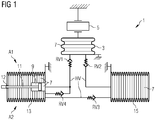
- FIG. 1 shows a first embodiment of a piezohydraulic actuator 1 according to the invention.
- Figure 1 shows the concept of the invention.
- a piezo actuator 5, which is coupled to a hydraulic system, is used as the drive element.
- the hydraulic system has four chambers. Namely a drive 3, a reservoir 15, an output 1 (A1) and an output 2 (A2).
- output 1 (A1) is designed as a hydraulic cylinder 9 and is mechanically firmly connected to the output 2 (A2) connected in parallel both on its housing and on a hydraulic piston 11.
- Output 1 (A1) has a smaller hydraulic cross-sectional area than output 2 (A2) and possibly as drive 3.
- PWM pulse width modulation
- the piezo 5 expands, as a result of which the fluid 7 in the drive 3 is compressed and the pressure increases due to the quasi-incompressibility.
- the check valve RV1 opens, so that oil as an exemplary embodiment for the hydraulic fluid 7 flows from the drive 3 into the output A1, that is to say into the hydraulic cylinder 9.
- the piezo stroke is translated.
- the PWM voltage at piezo 5 is reset to zero, which reduces the pressure in the drive 3 and, due to the volume reduction of the fluid 7, there is a negative pressure (a portion of the fluid 7 present in the drive 3 was previously in the output) A1 pumped).
- the check valve RV 2 opens and fluid 7 is sucked into the drive 3 from the reservoir 15.
- the PWM voltage can then be increased again and the cycle described above repeated.
- the repetition gradually pumps oil as an exemplary embodiment for the hydraulic fluid 7 from the reservoir 15 via the drive 3 into the output A1.
- the output A2 is also deflected, since the two are mechanically coupled to one another.
- Reference numeral 12 denotes a fastening point at which an output bellows 13 is mechanically connected to the hydraulic piston 11.
- the actuator 1 As soon as the first output A1 is moved or moves against a counterforce, for example as a result of an obstacle, it is necessary for the actuator 1 for operation that a large amount of force is built up. However, this is only possible to a limited extent with the first output A1, since the hydraulic cross-sectional area was chosen too small to provide a large speed ratio. The smaller the hydraulic area of the first output A1, the smaller the output force at a maximum pressure in the first output A1. For this reason, a check valve RV4 is installed between the first output A1 and the second output A2. If the pressure in the first output A1 rises due to a counterforce, the check valve RV4 opens, as a result of which the hydraulic fluid 7 is also pumped into the second output A2 in addition to the first output A1. Since the hydraulic cross section of the second output A2 is significantly larger, the output force provided by the second output A2 increases compared to the first output A1 at the same pressure.
- the retraction of the first and the second output A1 and A2 takes place according to this concept by means of a built-in leak.
- the third check valve RV3 can be provided with a simple leak, so that the hydraulic fluid 7 slowly drifts back from the second output A2 to the reservoir 15.
- FIG. 2 shows a second embodiment of a piezohydraulic actuator 1 according to the invention.
- This second embodiment largely has the same elements as the first embodiment according to Figure 1 on.
- a throttle 17 is installed in parallel to the check valve RV3.
- the throttle 17 can slowly provide a drifting back of the hydraulic fluid 7 from the second output A2 to the reservoir 15.
- Figure 2 shows a surface 19 of the hydraulic piston 11 of the hydraulic cylinder 9, a force transmission of the actuator 1 according to the invention being carried out by means of this surface 19.
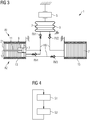
- Figure 3 shows a third embodiment of a piezohydraulic actuator 1 according to the invention.
- the third embodiment largely has the same system elements as the first embodiment according to Figure 1 on. Is accordingly Figure 3 as well as Figure 2 identified by the same reference numerals as in FIG.
- the mechanical output is different from Figure 2 not over the surface 19, but over the surface 21, which is formed via the output bellows 13 of the second output A2.
- the hydraulic piston 11 in the second output A2 can be mechanically connected to the hollow cylinder piston 11 either positively or non-positively at the fastening point of the output bellows 13.
- FIG. 4 shows an embodiment of a method according to the invention.
- the method relates to the operation of the piezohydraulic actuator 1 according to the invention, for example in accordance with the exemplary embodiments described above.
- a first step S1 the piezo actuator is expanded and the hydraulic fluid is compressed and pressed against the first check valve, which opens at a set pressure and the hydraulic fluid into the Hydraulic cylinder can flow and a translation or reduction of the piezo stroke is carried out.
- the piezo actuator is contracted, a negative pressure being generated in the drive bellows in such a way that the second check valve opens and hydraulic fluid flows from the reservoir into the drive bellows, thus completing a pumping cycle.
- Steps S1 and S2 can be repeated cyclically.
Landscapes
- Engineering & Computer Science (AREA)
- Physics & Mathematics (AREA)
- Fluid Mechanics (AREA)
- Mechanical Engineering (AREA)
- General Engineering & Computer Science (AREA)
- Actuator (AREA)
- Supply Devices, Intensifiers, Converters, And Telemotors (AREA)
- Reciprocating Pumps (AREA)
Applications Claiming Priority (2)
| Application Number | Priority Date | Filing Date | Title |
|---|---|---|---|
| DE102016208773.8A DE102016208773A1 (de) | 2016-05-20 | 2016-05-20 | Piezohydraulischer Aktor |
| PCT/EP2017/059514 WO2017198420A1 (de) | 2016-05-20 | 2017-04-21 | Piezohydraulischer aktor |
Publications (2)
| Publication Number | Publication Date |
|---|---|
| EP3443230A1 EP3443230A1 (de) | 2019-02-20 |
| EP3443230B1 true EP3443230B1 (de) | 2020-03-11 |
Family
ID=58664659
Family Applications (1)
| Application Number | Title | Priority Date | Filing Date |
|---|---|---|---|
| EP17720721.4A Active EP3443230B1 (de) | 2016-05-20 | 2017-04-21 | Piezohydraulischer aktor |
Country Status (9)
| Country | Link |
|---|---|
| US (1) | US10690154B2 (da) |
| EP (1) | EP3443230B1 (da) |
| JP (1) | JP6775034B2 (da) |
| KR (1) | KR102140047B1 (da) |
| CN (1) | CN109328268B (da) |
| DE (1) | DE102016208773A1 (da) |
| DK (1) | DK3443230T3 (da) |
| ES (1) | ES2786579T3 (da) |
| WO (1) | WO2017198420A1 (da) |
Families Citing this family (12)
| Publication number | Priority date | Publication date | Assignee | Title |
|---|---|---|---|---|
| DE102016208773A1 (de) | 2016-05-20 | 2017-11-23 | Siemens Aktiengesellschaft | Piezohydraulischer Aktor |
| DE102017202131A1 (de) * | 2017-02-10 | 2018-08-16 | Siemens Aktiengesellschaft | Piezohydraulischer Aktor und Verfahren zum Betreiben eines solchen piezohydraulischen Aktors |
| DE102018214970B4 (de) | 2018-09-04 | 2021-12-16 | Metismotion Gmbh | Aktorvorrichtung sowie Verfahren zum Betreiben einer solchen Aktorvorrichtung |
| JP7368011B2 (ja) * | 2019-04-17 | 2023-10-24 | メティスモーション ゲゼルシャフト ミット ベシュレンクテル ハフツング | アクチュエータ装置用のストローク伝達器 |
| WO2020211936A1 (de) * | 2019-04-17 | 2020-10-22 | Siemens Aktiengesellschaft | Hydraulische übersetzungseinheit für eine aktoreinrichtung |
| CN110514658B (zh) * | 2019-09-09 | 2021-01-15 | 张养华 | 一种用于医疗检验的试纸检验分析方法 |
| EP4103869A4 (en) * | 2020-02-14 | 2024-06-05 | Tetravision, LLC | Bidirectional thermally actuated component for use in medical devices |
| EP4104286B1 (de) * | 2020-02-14 | 2024-03-27 | MetisMotion GmbH | Aktorvorrichtung sowie verfahren zum betreiben einer solchen aktorvorrichtung |
| JP7644250B2 (ja) * | 2021-02-16 | 2025-03-11 | テトラビジョン,エルエルシー | 熱作動構成要素を有する脊椎アライメントシステム |
| AT526603B1 (de) * | 2023-01-03 | 2024-05-15 | Gear Systems Gmbh | Linearantrieb |
| EP4495431A1 (en) * | 2023-07-17 | 2025-01-22 | Airbus Operations GmbH | Hydraulic actuator and method for operating |
| WO2025062343A1 (en) * | 2023-09-20 | 2025-03-27 | Multi-Scale Medical Robotics Center Limited | Actuator for use with medical imaging modalities and system thereof |
Family Cites Families (15)
| Publication number | Priority date | Publication date | Assignee | Title |
|---|---|---|---|---|
| JPS6228507A (ja) * | 1985-07-26 | 1987-02-06 | Nippon Soken Inc | 電歪体駆動のアクチユエ−タ |
| JP2000314402A (ja) * | 1999-06-21 | 2000-11-14 | Kinya Ishikawa | 圧電素子の液圧拡大アクチュエーター |
| JP2003014402A (ja) | 2001-06-28 | 2003-01-15 | Shikoku Doki:Kk | 長尺物の繰出し・巻戻し装置及び巻尺 |
| US8037989B2 (en) | 2008-07-25 | 2011-10-18 | GM Global Technology Operations LLC | Torque transmitting device actuation system using a piezoelectric pump |
| DE102010027278B4 (de) * | 2010-07-15 | 2020-07-02 | Metismotion Gmbh | Thermisch volumenneutraler Hubübertrager sowie Dosierventil mit einem solchen Hubübertrager und Verwendung des Dosierventils |
| DE102010040612A1 (de) * | 2010-09-13 | 2012-03-15 | Siemens Aktiengesellschaft | Hydraulischer Temperaturkompensator und hydraulischer Hubübertrager |
| DE102012206834A1 (de) * | 2012-04-25 | 2013-10-31 | Siemens Aktiengesellschaft | Aktorvorrichtung und Verfahren zum Einstellen einer Position eines linear beweglichen Elements |
| DE102012211313A1 (de) * | 2012-06-29 | 2014-01-02 | Siemens Aktiengesellschaft | Aktorvorrichtung und Verfahren zum Einstellen einer Position eines linear beweglichen Elements |
| DE102013205044B4 (de) * | 2013-03-21 | 2022-08-11 | Metismotion Gmbh | Aktorvorrichtung |
| DE102013016078A1 (de) | 2013-09-27 | 2015-04-02 | Man Truck & Bus Ag | Feder-Dämpfer-System zur Verwendung in Lagern oder als Dämpfer |
| WO2015044420A2 (de) * | 2013-09-27 | 2015-04-02 | Siemens Aktiengesellschaft | Hubsystem, verfahren zur elektrischen prüfung, schwingungsdämpfer und maschinenaggregat |
| DE102013219759A1 (de) * | 2013-09-30 | 2015-04-02 | Siemens Aktiengesellschaft | Aktorvorrichtung und Verfahren zum Einstellen einer Position eines linear beweglichen Elements |
| DE102016205275A1 (de) * | 2016-03-31 | 2017-10-05 | Siemens Aktiengesellschaft | Hydraulischer Aktor, Roboterarm, Roboterhand und Verfahren zum Betrieb |
| DE102016208773A1 (de) | 2016-05-20 | 2017-11-23 | Siemens Aktiengesellschaft | Piezohydraulischer Aktor |
| DE102017202131A1 (de) * | 2017-02-10 | 2018-08-16 | Siemens Aktiengesellschaft | Piezohydraulischer Aktor und Verfahren zum Betreiben eines solchen piezohydraulischen Aktors |
-
2016
- 2016-05-20 DE DE102016208773.8A patent/DE102016208773A1/de not_active Ceased
-
2017
- 2017-04-21 CN CN201780039523.9A patent/CN109328268B/zh active Active
- 2017-04-21 DK DK17720721.4T patent/DK3443230T3/da active
- 2017-04-21 WO PCT/EP2017/059514 patent/WO2017198420A1/de not_active Ceased
- 2017-04-21 EP EP17720721.4A patent/EP3443230B1/de active Active
- 2017-04-21 US US16/302,223 patent/US10690154B2/en active Active
- 2017-04-21 JP JP2018560511A patent/JP6775034B2/ja active Active
- 2017-04-21 KR KR1020187036758A patent/KR102140047B1/ko active Active
- 2017-04-21 ES ES17720721T patent/ES2786579T3/es active Active
Non-Patent Citations (1)
| Title |
|---|
| None * |
Also Published As
| Publication number | Publication date |
|---|---|
| WO2017198420A1 (de) | 2017-11-23 |
| US20190271336A1 (en) | 2019-09-05 |
| ES2786579T3 (es) | 2020-10-13 |
| KR20190006016A (ko) | 2019-01-16 |
| JP6775034B2 (ja) | 2020-10-28 |
| US10690154B2 (en) | 2020-06-23 |
| JP2019522152A (ja) | 2019-08-08 |
| DE102016208773A1 (de) | 2017-11-23 |
| DK3443230T3 (da) | 2020-05-11 |
| CN109328268B (zh) | 2020-06-16 |
| KR102140047B1 (ko) | 2020-07-31 |
| EP3443230A1 (de) | 2019-02-20 |
| CN109328268A (zh) | 2019-02-12 |
Similar Documents
| Publication | Publication Date | Title |
|---|---|---|
| EP3443230B1 (de) | Piezohydraulischer aktor | |
| EP2812584B1 (de) | Aktorvorrichtung und verfahren zum einstellen einer position eines linear beweglichen elements | |
| DE102008014964B4 (de) | Positionssteuermechanismus für doppelt wirkende Pneumatikzylinder | |
| EP3174650B1 (de) | Stanzvorrichtung und verfahren zum stanzen eines werkstücks | |
| DE102014218885A1 (de) | Hydraulischer Antrieb mit Eilhub und Lasthub | |
| EP1780420B1 (de) | Hydraulische Druckversorgungseinheit und elektrohydraulische Arbeitseinheit | |
| WO2015185644A1 (de) | Hydrauliksystem | |
| EP3563064B1 (de) | Piezohydraulischer aktor und verfahren zum betreiben eines solchen piezohydraulischen aktors | |
| EP2501942B1 (de) | Hochspannungsschalter | |
| DE3637404C2 (da) | ||
| DE3013381C2 (de) | Arbeitskolben-Zylinder-Einheit | |
| EP2466171A1 (de) | Vorrichtung zur Betätigung eines Arbeitszylinders, Vorrichtung zur Druckölversorgung von Automatiesierungskomponenten eines automatisierten Schaltgetriebes und Verwendung eines pneumatisch-hydraulischen Druckwandlers | |
| WO2014001083A1 (de) | Aktorvorrichtung und verfahren zum einstellen einer position eines linear beweglichen elements | |
| DE102013227053B4 (de) | Hydraulische Achse | |
| EP2535624A1 (de) | Druckbegrenzungsventil | |
| DE102018203367A1 (de) | Hydrostatischer Linearantrieb | |
| EP4159373B1 (de) | Spannsystem mit eil- und krafthub und verfahren zum betreiben eines spannsystems | |
| DE102010033840A1 (de) | Hydraulische Schaltungsanordnung zum Betrieb mechanisch gekoppelter, druckmittelbetätigter Verdrängereinheiten | |
| EP3956569A1 (de) | Hydraulische übersetzungseinheit für eine aktoreinrichtung | |
| WO2019185362A1 (de) | Pressenantrieb mit energierückgewinnung | |
| DE102016206015A1 (de) | Hydraulische Schaltelementanordnung | |
| DE102005041252B4 (de) | Elektrohydraulischer Pressenantrieb | |
| DE102004061298A1 (de) | Linearantrieb | |
| WO2019076849A1 (de) | Aktorvorrichtung | |
| DE102009006053A1 (de) | Antriebsvorrichtung mit einer elektromotorischen Antriebseinheit |
Legal Events
| Date | Code | Title | Description |
|---|---|---|---|
| STAA | Information on the status of an ep patent application or granted ep patent |
Free format text: STATUS: UNKNOWN |
|
| STAA | Information on the status of an ep patent application or granted ep patent |
Free format text: STATUS: THE INTERNATIONAL PUBLICATION HAS BEEN MADE |
|
| PUAI | Public reference made under article 153(3) epc to a published international application that has entered the european phase |
Free format text: ORIGINAL CODE: 0009012 |
|
| STAA | Information on the status of an ep patent application or granted ep patent |
Free format text: STATUS: REQUEST FOR EXAMINATION WAS MADE |
|
| 17P | Request for examination filed |
Effective date: 20181112 |
|
| AK | Designated contracting states |
Kind code of ref document: A1 Designated state(s): AL AT BE BG CH CY CZ DE DK EE ES FI FR GB GR HR HU IE IS IT LI LT LU LV MC MK MT NL NO PL PT RO RS SE SI SK SM TR |
|
| AX | Request for extension of the european patent |
Extension state: BA ME |
|
| RAP1 | Party data changed (applicant data changed or rights of an application transferred) |
Owner name: METISMOTION GMBH |
|
| DAV | Request for validation of the european patent (deleted) | ||
| DAX | Request for extension of the european patent (deleted) | ||
| GRAP | Despatch of communication of intention to grant a patent |
Free format text: ORIGINAL CODE: EPIDOSNIGR1 |
|
| STAA | Information on the status of an ep patent application or granted ep patent |
Free format text: STATUS: GRANT OF PATENT IS INTENDED |
|
| INTG | Intention to grant announced |
Effective date: 20190927 |
|
| GRAS | Grant fee paid |
Free format text: ORIGINAL CODE: EPIDOSNIGR3 |
|
| GRAJ | Information related to disapproval of communication of intention to grant by the applicant or resumption of examination proceedings by the epo deleted |
Free format text: ORIGINAL CODE: EPIDOSDIGR1 |
|
| GRAL | Information related to payment of fee for publishing/printing deleted |
Free format text: ORIGINAL CODE: EPIDOSDIGR3 |
|
| STAA | Information on the status of an ep patent application or granted ep patent |
Free format text: STATUS: REQUEST FOR EXAMINATION WAS MADE |
|
| GRAR | Information related to intention to grant a patent recorded |
Free format text: ORIGINAL CODE: EPIDOSNIGR71 |
|
| STAA | Information on the status of an ep patent application or granted ep patent |
Free format text: STATUS: GRANT OF PATENT IS INTENDED |
|
| INTC | Intention to grant announced (deleted) | ||
| GRAA | (expected) grant |
Free format text: ORIGINAL CODE: 0009210 |
|
| STAA | Information on the status of an ep patent application or granted ep patent |
Free format text: STATUS: THE PATENT HAS BEEN GRANTED |
|
| AK | Designated contracting states |
Kind code of ref document: B1 Designated state(s): AL AT BE BG CH CY CZ DE DK EE ES FI FR GB GR HR HU IE IS IT LI LT LU LV MC MK MT NL NO PL PT RO RS SE SI SK SM TR |
|
| INTG | Intention to grant announced |
Effective date: 20200203 |
|
| REG | Reference to a national code |
Ref country code: GB Ref legal event code: FG4D Free format text: NOT ENGLISH |
|
| REG | Reference to a national code |
Ref country code: CH Ref legal event code: EP |
|
| REG | Reference to a national code |
Ref country code: AT Ref legal event code: REF Ref document number: 1243464 Country of ref document: AT Kind code of ref document: T Effective date: 20200315 |
|
| REG | Reference to a national code |
Ref country code: IE Ref legal event code: FG4D Free format text: LANGUAGE OF EP DOCUMENT: GERMAN |
|
| REG | Reference to a national code |
Ref country code: DE Ref legal event code: R096 Ref document number: 502017004209 Country of ref document: DE |
|
| REG | Reference to a national code |
Ref country code: CH Ref legal event code: NV Representative=s name: KELLER AND PARTNER PATENTANWAELTE AG, CH |
|
| REG | Reference to a national code |
Ref country code: DK Ref legal event code: T3 Effective date: 20200507 |
|
| REG | Reference to a national code |
Ref country code: NL Ref legal event code: FP |
|
| PG25 | Lapsed in a contracting state [announced via postgrant information from national office to epo] |
Ref country code: RS Free format text: LAPSE BECAUSE OF FAILURE TO SUBMIT A TRANSLATION OF THE DESCRIPTION OR TO PAY THE FEE WITHIN THE PRESCRIBED TIME-LIMIT Effective date: 20200311 Ref country code: NO Free format text: LAPSE BECAUSE OF FAILURE TO SUBMIT A TRANSLATION OF THE DESCRIPTION OR TO PAY THE FEE WITHIN THE PRESCRIBED TIME-LIMIT Effective date: 20200611 Ref country code: FI Free format text: LAPSE BECAUSE OF FAILURE TO SUBMIT A TRANSLATION OF THE DESCRIPTION OR TO PAY THE FEE WITHIN THE PRESCRIBED TIME-LIMIT Effective date: 20200311 |
|
| PG25 | Lapsed in a contracting state [announced via postgrant information from national office to epo] |
Ref country code: SE Free format text: LAPSE BECAUSE OF FAILURE TO SUBMIT A TRANSLATION OF THE DESCRIPTION OR TO PAY THE FEE WITHIN THE PRESCRIBED TIME-LIMIT Effective date: 20200311 Ref country code: LV Free format text: LAPSE BECAUSE OF FAILURE TO SUBMIT A TRANSLATION OF THE DESCRIPTION OR TO PAY THE FEE WITHIN THE PRESCRIBED TIME-LIMIT Effective date: 20200311 Ref country code: HR Free format text: LAPSE BECAUSE OF FAILURE TO SUBMIT A TRANSLATION OF THE DESCRIPTION OR TO PAY THE FEE WITHIN THE PRESCRIBED TIME-LIMIT Effective date: 20200311 Ref country code: BG Free format text: LAPSE BECAUSE OF FAILURE TO SUBMIT A TRANSLATION OF THE DESCRIPTION OR TO PAY THE FEE WITHIN THE PRESCRIBED TIME-LIMIT Effective date: 20200611 Ref country code: GR Free format text: LAPSE BECAUSE OF FAILURE TO SUBMIT A TRANSLATION OF THE DESCRIPTION OR TO PAY THE FEE WITHIN THE PRESCRIBED TIME-LIMIT Effective date: 20200612 |
|
| REG | Reference to a national code |
Ref country code: LT Ref legal event code: MG4D |
|
| REG | Reference to a national code |
Ref country code: CH Ref legal event code: PFA Owner name: METISMOTION GMBH, DE Free format text: FORMER OWNER: METISMOTION GMBH, DE |
|
| REG | Reference to a national code |
Ref country code: ES Ref legal event code: FG2A Ref document number: 2786579 Country of ref document: ES Kind code of ref document: T3 Effective date: 20201013 |
|
| PG25 | Lapsed in a contracting state [announced via postgrant information from national office to epo] |
Ref country code: SK Free format text: LAPSE BECAUSE OF FAILURE TO SUBMIT A TRANSLATION OF THE DESCRIPTION OR TO PAY THE FEE WITHIN THE PRESCRIBED TIME-LIMIT Effective date: 20200311 Ref country code: CZ Free format text: LAPSE BECAUSE OF FAILURE TO SUBMIT A TRANSLATION OF THE DESCRIPTION OR TO PAY THE FEE WITHIN THE PRESCRIBED TIME-LIMIT Effective date: 20200311 Ref country code: IS Free format text: LAPSE BECAUSE OF FAILURE TO SUBMIT A TRANSLATION OF THE DESCRIPTION OR TO PAY THE FEE WITHIN THE PRESCRIBED TIME-LIMIT Effective date: 20200711 Ref country code: RO Free format text: LAPSE BECAUSE OF FAILURE TO SUBMIT A TRANSLATION OF THE DESCRIPTION OR TO PAY THE FEE WITHIN THE PRESCRIBED TIME-LIMIT Effective date: 20200311 Ref country code: EE Free format text: LAPSE BECAUSE OF FAILURE TO SUBMIT A TRANSLATION OF THE DESCRIPTION OR TO PAY THE FEE WITHIN THE PRESCRIBED TIME-LIMIT Effective date: 20200311 Ref country code: SM Free format text: LAPSE BECAUSE OF FAILURE TO SUBMIT A TRANSLATION OF THE DESCRIPTION OR TO PAY THE FEE WITHIN THE PRESCRIBED TIME-LIMIT Effective date: 20200311 Ref country code: PT Free format text: LAPSE BECAUSE OF FAILURE TO SUBMIT A TRANSLATION OF THE DESCRIPTION OR TO PAY THE FEE WITHIN THE PRESCRIBED TIME-LIMIT Effective date: 20200805 Ref country code: LT Free format text: LAPSE BECAUSE OF FAILURE TO SUBMIT A TRANSLATION OF THE DESCRIPTION OR TO PAY THE FEE WITHIN THE PRESCRIBED TIME-LIMIT Effective date: 20200311 |
|
| REG | Reference to a national code |
Ref country code: DE Ref legal event code: R097 Ref document number: 502017004209 Country of ref document: DE |
|
| PG25 | Lapsed in a contracting state [announced via postgrant information from national office to epo] |
Ref country code: MC Free format text: LAPSE BECAUSE OF FAILURE TO SUBMIT A TRANSLATION OF THE DESCRIPTION OR TO PAY THE FEE WITHIN THE PRESCRIBED TIME-LIMIT Effective date: 20200311 |
|
| PLBE | No opposition filed within time limit |
Free format text: ORIGINAL CODE: 0009261 |
|
| STAA | Information on the status of an ep patent application or granted ep patent |
Free format text: STATUS: NO OPPOSITION FILED WITHIN TIME LIMIT |
|
| PG25 | Lapsed in a contracting state [announced via postgrant information from national office to epo] |
Ref country code: LU Free format text: LAPSE BECAUSE OF NON-PAYMENT OF DUE FEES Effective date: 20200421 |
|
| REG | Reference to a national code |
Ref country code: BE Ref legal event code: MM Effective date: 20200430 |
|
| 26N | No opposition filed |
Effective date: 20201214 |
|
| PG25 | Lapsed in a contracting state [announced via postgrant information from national office to epo] |
Ref country code: PL Free format text: LAPSE BECAUSE OF FAILURE TO SUBMIT A TRANSLATION OF THE DESCRIPTION OR TO PAY THE FEE WITHIN THE PRESCRIBED TIME-LIMIT Effective date: 20200311 Ref country code: BE Free format text: LAPSE BECAUSE OF NON-PAYMENT OF DUE FEES Effective date: 20200430 Ref country code: SI Free format text: LAPSE BECAUSE OF FAILURE TO SUBMIT A TRANSLATION OF THE DESCRIPTION OR TO PAY THE FEE WITHIN THE PRESCRIBED TIME-LIMIT Effective date: 20200311 |
|
| PG25 | Lapsed in a contracting state [announced via postgrant information from national office to epo] |
Ref country code: IE Free format text: LAPSE BECAUSE OF NON-PAYMENT OF DUE FEES Effective date: 20200421 |
|
| PG25 | Lapsed in a contracting state [announced via postgrant information from national office to epo] |
Ref country code: TR Free format text: LAPSE BECAUSE OF FAILURE TO SUBMIT A TRANSLATION OF THE DESCRIPTION OR TO PAY THE FEE WITHIN THE PRESCRIBED TIME-LIMIT Effective date: 20200311 Ref country code: MT Free format text: LAPSE BECAUSE OF FAILURE TO SUBMIT A TRANSLATION OF THE DESCRIPTION OR TO PAY THE FEE WITHIN THE PRESCRIBED TIME-LIMIT Effective date: 20200311 Ref country code: CY Free format text: LAPSE BECAUSE OF FAILURE TO SUBMIT A TRANSLATION OF THE DESCRIPTION OR TO PAY THE FEE WITHIN THE PRESCRIBED TIME-LIMIT Effective date: 20200311 |
|
| PG25 | Lapsed in a contracting state [announced via postgrant information from national office to epo] |
Ref country code: MK Free format text: LAPSE BECAUSE OF FAILURE TO SUBMIT A TRANSLATION OF THE DESCRIPTION OR TO PAY THE FEE WITHIN THE PRESCRIBED TIME-LIMIT Effective date: 20200311 Ref country code: AL Free format text: LAPSE BECAUSE OF FAILURE TO SUBMIT A TRANSLATION OF THE DESCRIPTION OR TO PAY THE FEE WITHIN THE PRESCRIBED TIME-LIMIT Effective date: 20200311 |
|
| REG | Reference to a national code |
Ref country code: AT Ref legal event code: MM01 Ref document number: 1243464 Country of ref document: AT Kind code of ref document: T Effective date: 20220421 |
|
| PG25 | Lapsed in a contracting state [announced via postgrant information from national office to epo] |
Ref country code: AT Free format text: LAPSE BECAUSE OF NON-PAYMENT OF DUE FEES Effective date: 20220421 |
|
| PGFP | Annual fee paid to national office [announced via postgrant information from national office to epo] |
Ref country code: NL Payment date: 20250422 Year of fee payment: 9 |
|
| PGFP | Annual fee paid to national office [announced via postgrant information from national office to epo] |
Ref country code: DE Payment date: 20250425 Year of fee payment: 9 |
|
| PGFP | Annual fee paid to national office [announced via postgrant information from national office to epo] |
Ref country code: ES Payment date: 20250519 Year of fee payment: 9 Ref country code: GB Payment date: 20250423 Year of fee payment: 9 Ref country code: DK Payment date: 20250423 Year of fee payment: 9 |
|
| PGFP | Annual fee paid to national office [announced via postgrant information from national office to epo] |
Ref country code: IT Payment date: 20250430 Year of fee payment: 9 |
|
| PGFP | Annual fee paid to national office [announced via postgrant information from national office to epo] |
Ref country code: FR Payment date: 20250422 Year of fee payment: 9 |
|
| PGFP | Annual fee paid to national office [announced via postgrant information from national office to epo] |
Ref country code: CH Payment date: 20250501 Year of fee payment: 9 |