EP3443188B1 - Kraftfahrzeugschloss - Google Patents
Kraftfahrzeugschloss Download PDFInfo
- Publication number
- EP3443188B1 EP3443188B1 EP17706140.5A EP17706140A EP3443188B1 EP 3443188 B1 EP3443188 B1 EP 3443188B1 EP 17706140 A EP17706140 A EP 17706140A EP 3443188 B1 EP3443188 B1 EP 3443188B1
- Authority
- EP
- European Patent Office
- Prior art keywords
- motor vehicle
- light
- lock
- vehicle lock
- light guide
- Prior art date
- Legal status (The legal status is an assumption and is not a legal conclusion. Google has not performed a legal analysis and makes no representation as to the accuracy of the status listed.)
- Active
Links
Images

Classifications
-
- E—FIXED CONSTRUCTIONS
- E05—LOCKS; KEYS; WINDOW OR DOOR FITTINGS; SAFES
- E05B—LOCKS; ACCESSORIES THEREFOR; HANDCUFFS
- E05B81/00—Power-actuated vehicle locks
- E05B81/54—Electrical circuits
-
- E—FIXED CONSTRUCTIONS
- E05—LOCKS; KEYS; WINDOW OR DOOR FITTINGS; SAFES
- E05B—LOCKS; ACCESSORIES THEREFOR; HANDCUFFS
- E05B17/00—Accessories in connection with locks
- E05B17/10—Illuminating devices on or for locks or keys; Transparent or translucent lock parts; Indicator lights
-
- E—FIXED CONSTRUCTIONS
- E05—LOCKS; KEYS; WINDOW OR DOOR FITTINGS; SAFES
- E05B—LOCKS; ACCESSORIES THEREFOR; HANDCUFFS
- E05B17/00—Accessories in connection with locks
- E05B17/22—Means for operating or controlling lock or fastening device accessories, i.e. other than the fastening members, e.g. switches, indicators
- E05B17/226—Displays on locks, e.g. LED or LCD screens
-
- B—PERFORMING OPERATIONS; TRANSPORTING
- B60—VEHICLES IN GENERAL
- B60Q—ARRANGEMENT OF SIGNALLING OR LIGHTING DEVICES, THE MOUNTING OR SUPPORTING THEREOF OR CIRCUITS THEREFOR, FOR VEHICLES IN GENERAL
- B60Q1/00—Arrangement of optical signalling or lighting devices, the mounting or supporting thereof or circuits therefor
- B60Q1/26—Arrangement of optical signalling or lighting devices, the mounting or supporting thereof or circuits therefor the devices being primarily intended to indicate the vehicle, or parts thereof, or to give signals, to other traffic
- B60Q1/2661—Arrangement of optical signalling or lighting devices, the mounting or supporting thereof or circuits therefor the devices being primarily intended to indicate the vehicle, or parts thereof, or to give signals, to other traffic mounted on parts having other functions
- B60Q1/2669—Arrangement of optical signalling or lighting devices, the mounting or supporting thereof or circuits therefor the devices being primarily intended to indicate the vehicle, or parts thereof, or to give signals, to other traffic mounted on parts having other functions on door or boot handles
Definitions
- the invention relates to a motor vehicle lock, in particular a motor vehicle door lock, comprising a lock housing, an electrical power supply, a light source and a light guide element cooperating with the light source, the light guide element being designed as an integral part of the motor vehicle lock, so that the motor vehicle lock is at least partially illuminable.
- motor vehicles are used in road traffic, they are subject to a number of safety regulations.
- the lighting of a motor vehicle has come more and more to the fore in recent years.
- the light on the motor vehicle is therefore a safety-relevant feature.
- a motor vehicle locking device has become known in which the rotary latch arranged in the locking system is provided with a luminescent surface so that in the dark and / or in poor visibility a light effect is generated which increases the safety of the motor vehicle.
- the publication shows a motor vehicle lock for a side door in that the rotary latch of the motor vehicle lock remains visible in the open state through an inlet mouth of the motor vehicle lock, even if the rotary latch or the locking mechanism of the motor vehicle lock is open that is unlocked state.
- taillights and reflectors have also become known that indicate that the door is being opened or that either reflect a light falling on the door while the door is being opened or, as a light source, indicate that the door is open.
- a door furnishing element is disclosed which is equipped with various lights such as a reading light, a rear light and a floor light.
- the door device element can comprise reflectors.
- a rear light can also be integrated into an edge of the inlet slot, the inlet slot being widened evenly. All of these measures serve to alert road users to an open or opening door and thus to ensure the safety of traffic.
- a motor vehicle lock arrangement for a motor vehicle door has become known in which the motor vehicle lock with a lighting arrangement is formed, the lighting arrangement having an electrical light source, the light radiation of which can be emitted via a lighting element.
- the light source can be let into the lock housing in such a way that only the light-emitting surface of the light source points outward from the lock housing.
- a light source which interacts with a light guide which transmits the light from the light source to a light-emitting element, the light-emitting element comprising optics for emitting the light radiation.
- the display means or lighting means known from the prior art have the disadvantage that they either do not provide sufficient light intensity, require additional assembly steps as a separate lighting means and / or are dependent on additional openings in the motor vehicle.
- a motor vehicle lock of the structure described above is in the US 9,127,477 B1 described. In the end, it is a matter of illuminating an associated handle of the motor vehicle door lock or a recess receiving the handle. A solar cell and a battery are also provided for this purpose. In this way, the lighting can be switched on with the help of a sensor.
- Illuminants integrated in a side door lock or a tailgate are provided.
- the lamp is it is one or more light diodes which are arranged in the inlet area of an inlet mouth.
- the invention is based on the technical problem of further increasing the security of a motor vehicle and, moreover, of providing a cost-effective and structurally simple security system for a motor vehicle lock.
- a motor vehicle lock comprising a lock housing, an electrical power supply, a light source and a light guide element cooperating with the light source, the light guide element being designed as an integral part of the motor vehicle lock , so that the motor vehicle lock can be illuminated at least in some areas, an LED being used as the illuminant, which is arranged directly on a printed circuit board, and the illuminant from the illuminant by means of the light guide element emitted light is guided in the direction of an inlet mouth with a rotary latch arranged in the inlet mouth, with light exit surfaces of the light guide element being arranged around the inlet mouth.
- the inventive design of the motor vehicle lock now creates the possibility of providing a light-intensive security system for a motor vehicle with which the security of a motor vehicle is increased and which is at the same time designed as an integral part of the motor vehicle lock.
- the design as an integral component offers the possibility of providing a cost-effective solution for achieving a securing means, which can be implemented at the same time with minimal structural effort.
- Motor vehicle locks are not only used for doors, flaps, hoods and sliding doors, but can also be used, for example, in the area of covers such as those used for convertible roofs, for example.
- the lighting device according to the invention can also, for example, in the case of flaps, serve to indicate whether the flap has been fully and correctly closed.
- the motor vehicle lock can comprise a microswitch which is only switched when the motor vehicle lock has reached its final locked position. In the case of motor vehicle door locks, this is, for example, a main locking position of the locking mechanism in which a rotary latch is locked by means of a pawl, for example.
- the motor vehicle lock comprises a lock housing, which is preferably made of plastic.
- a lock housing preferably consists of two parts, a housing base and a housing cover, which can usually be connected to one another in a watertight manner.
- the lock housing is designed in such a way that an opening area of the lock which interacts with a locking bolt, for example, is designed to be circumferentially enclosed. This opening area is also called the opening mouth.
- the lock housing encloses a lock plate to stabilize the lock and in particular for the stable mounting of a locking mechanism located in the lock.
- the lock plate can at least partially enclose the lock housing, and depending on the embodiment, the lock plate can also enclose the opening mouth.
- the motor vehicle lock further comprises a power supply, the electrical current being introduced into the lock mostly by means of a stretcher, the current being distributable via conductor tracks and / or a circuit board.
- the illuminant is preferably arranged directly on a printed circuit board.
- an LED is used as the light source, which is arranged directly on the circuit board.
- the direct arrangement on the circuit board offers the advantage that control is facilitated and at the same time no additional electrical conductor tracks are required for contacting the illuminant.
- the use of a light guide element is advantageous because it creates the possibility of using the light source anywhere in the motor vehicle lock and in particular directly on the conductor track already present in the lock and / or to arrange circuit board. The light guide element then creates the possibility of forwarding the light emitted by the illuminant to a surface of the motor vehicle lock.
- the light guide element is designed as an integral part of the motor vehicle lock.
- An integral component here means that the light guide element is formed from the lock housing at least in some areas.
- light can be introduced directly into the lock housing.
- the lock housing has an extension which then functions as a light guide element and can be adapted directly to the illuminant.
- the light guide element is integrated into the lock housing.
- the light guide element forms an integral part of the lock housing, with areas of the lock housing being substituted by the light guide element.
- the light guide element thus forms an integral part of the housing of the motor vehicle lock. If, in one embodiment, the light-guiding element or the lighting means is arranged directly behind or on the light-guiding element, an extension on the light-guiding element can also be dispensed with, so that the Light guide element is possible. Even if a lighting means is preferably mentioned here, it is also conceivable that two or more lighting means are provided in the motor vehicle lock.
- two or more illuminants it is of course also conceivable that two or more light guide elements are arranged in the motor vehicle lock, which interact with one or more illuminants.
- branches or branches can also be provided in the light guide element, so that separate areas can be aligned in the motor vehicle lock.
- the motor vehicle lock can have openings through which, for example, emergency actuation, a child safety device can be reached or, for example, the locking mechanism interacts with a lock holder bracket.
- the light from the illuminant can be passed on directly to the opening in the motor vehicle lock by means of the light guide element.
- the light guide element encloses the opening at least in some areas. Depending on the size of the opening and the desired signal effect or security effect, it can be useful to illuminate only partial areas of the opening or it can also be advantageous that the opening is completely enclosed by the light guide element. If the light guide element is formed, for example, as a partial element or from a plurality of two or more parts on the circumference of the opening, a further warning function can be achieved. On the one hand, symbols can be achieved by a number of light guide elements on the circumference and, in addition, it is also conceivable that a dynamic effect can be achieved in the lamps by using two or more lamps. If the lighting means are switched on one after the other, for example, a display that appears to be moved can be generated. In addition, an effect that supports a warning and / or safety function can also be achieved by different colors of the lighting means or the light guide means.
- the light guide element is designed in one piece with the lock housing.
- the one-piece design of the lock housing creates the possibility of producing the lock housing with a warning and / or safety function in an extremely cost-effective manner. Assembly steps can be omitted, the connection to the lighting means can be made easier and, in addition, areas in the motor vehicle lock that are difficult to access for a lighting means or a light guide element can be illuminated.
- the One-piece design also offers the advantage that the light guide element can be securely fixed directly. This results in assembly-related, that is, manufacturing-related advantages, structural advantages, but also advantages with regard to optimal illumination of the motor vehicle lock.
- Motor vehicle locks mostly comprise at least one electric motor with which, for example, a central lock can be controlled.
- an electrical component carrier can be arranged in the lock.
- the electrical component carrier can be designed as a separate component or as an integral part of the lock housing.
- the lighting means can then be soldered and / or, for example, directly on the electrical component carrier be plugged in. This has the advantage that no separate control lines or lines for the power supply to the lighting means need to be formed.
- the illuminant is attached to a printed circuit board located on the electrical component carrier on or in the lock, so that again no separate control and / or power lines to the illuminant need to be formed.
- the light emitted by the illuminant can then be passed on to the illuminable areas of the motor vehicle lock by means of the light guide element.
- the light guide element comprises light-scattering elements at least in some areas, preferably in the area of a light exit surface.
- the light intensity that can be emitted to the environment by means of the light guide element depends on the one hand on the amount of light introduced into the light guide element and on the other hand on how the light exits the light guide element. In order, on the one hand, to allow a high light intensity to emerge from the light element and, on the other hand, to achieve a uniform distribution over the exit surface, light-scattering elements can be present in the light-guiding element.
- the light-scattering elements have the effect that even with only a small diameter of a light guide element that extends from the illuminant to the light exit surface, the light is evenly distributed over the entire light exit surface.
- the extent of the light guide element can differ.
- the light guide element can have a small diameter in the connection area to the lighting means, with the light exit surface extending over a larger area or several areas can extend.
- the light exit surface can thus have an extent that can be distinguished from the light-guiding light-guiding element in the motor vehicle locking system.
- light-scattering particles in the light-conducting plastic can advantageously be used.
- the light-guiding element comprises at least some areas, preferably in a light-guiding area, light-focusing and / or reflective elements and / or surfaces, this results in a further advantageous embodiment of the invention.
- surfaces on a light exit surface can be light-focusing. It is conceivable here for the light exit surface to be designed, for example, in the shape of a cone or as a hollow surface. Depending on the design of the surface, the light emerging from the light guide element can then be focused. It is thus conceivable, for example, to illuminate specific areas around the door or the door itself in a targeted manner. Additional reflective areas on the light guide element can serve, for example, to increase the light intensity or the visibility of the light guide element.
- the light guide element and in particular the visible areas of the light guide element in the motor vehicle lock serve to increase traffic safety.
- light-reflecting surfaces are now additionally formed on the light-guiding element, on the one hand the light in the light-guiding element can be focused and / or guided in a targeted manner and, on the other hand, it is possible that a light that shines from outside onto the motor vehicle is reflected by the light-guiding element, which increases the visibility of the Light guide element additionally increased.
- Light focusing and / or reflective elements and / or surfaces can thus serve, individually or in combination, to increase the light intensity that can be emitted by the light guide element.
- At least the light guide element is formed from polycarbonate or polymethyl methacrylate.
- Polycarbonate (PC) or polymethyl methacrylate (PMMA) are synthetic, transparent, thermoplastic plastics with an advantageous light-guiding property.
- a high light intensity can be emitted to the surroundings of the motor vehicle by means of the light guide element, so that safety in the motor vehicle can be significantly increased.
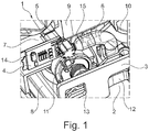
- FIG. 1 a three-dimensional view of a partial area of a motor vehicle lock 1 is shown. Shown is an area of the motor vehicle lock 1 in the area of an inlet mouth with a lock plate 3 enclosing the inlet mouth 2.
- a lighting means 5 is arranged in electrical contact on a circuit board 4, a light guide element being connected to the lighting means 5.
- the circuit board 4 is directly connected to an electrical component carrier 7.
- a part of a lock housing, an electric motor 9, adjusting means 10, 11 and a rotary latch 12 can be seen as further components.
- An opening 13 in the lock plate 3 is used, for example, to connect the lock plate 3 to the lock housing 8.
- Further electrotechnical components 14 are arranged on the circuit board 4, which are used to control and / or regulate the lighting means 5 and / or the motor 9, for example .
- the illuminant 5 has a funnel-shaped extension 15 with which the illuminant is connected to the light guide element 6.
- the light guide element can be designed in one piece with the lock housing 8 or form an integral part of the lock housing 8 as a separate component. Depending on the arrangement of the lighting means 5 in the motor vehicle lock 1, a separate design or a one-piece design of the light guide element 6 with the lock housing 8 can be advantageous. In the event that the light guide element forms an integral part of the lock housing 8 as a separate component, it is conceivable to arrange the light guide element by means of clipping, joining or gluing. According to the invention, the light emitted by the lighting means 5 is guided in the direction of the rotary latch 12 or the inlet mouth 2 by means of the light guide element 6.
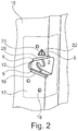
- FIG. 2 a view of a motor vehicle door 16 in the area of a side door lock 17 is shown.
- the inlet mouth 2 with the rotary latch 12 arranged in the inlet mouth 2 can be seen.
- the motor vehicle side door lock 17 is connected to the motor vehicle door 16 by means of a screw connection 18.
- a motor vehicle door is explicitly shown in this exemplary embodiment, the invention is not restricted to this, but can of course also be used for sliding doors, flaps and / or covers.
- light exit surfaces 19, 20 of the light guide element 6 are arranged around the inlet mouth 2.
- the light exit surfaces 19, 20 are part of the light guide element 6. That is, the light exit surfaces are components of the light guide element and can, for example, be formed in one piece from a plastic.
- the light guide element 6 extends around the inlet mouth 2 of the motor vehicle side door lock 17 only in some areas.
- a light exit surface 21 can be designed as a separate surface 21.
- the light exit surface can also include a symbol 22, for example, in order to increase a signaling effect, for example.
- the illustrated embodiments of the light exit surfaces 19, 20, 21, 23, 24, 25, 26 are only examples which are intended to show that different shapes and configurations of a light guide element 6 for illumination are conceivable.
- the light exit surface 24 encloses the inlet mouth 2 in some areas, but can, for example, from the combination of the light exit surfaces 23, 24, completely enclose the inlet mouth.
- extended areas 25 of the inlet mouth 2 are illuminated so that symbols such as traffic signs can also be displayed.
- the inlet mouth 2 can be illuminated over the entire area with the light guide element 6.
- an increased signaling effect can be achieved by means of the light guide element and consequently the safety of the motor vehicle can be increased.
Landscapes
- Lock And Its Accessories (AREA)
- Lighting Device Outwards From Vehicle And Optical Signal (AREA)
Description
- Die Erfindung betrifft ein Kraftfahrzeug-Schloss, insbesondere ein Kraftfahrzeug-Türschloss, umfassend ein Schlossgehäuse, eine elektrische Stromversorgung, ein Leuchtmittel und ein mit dem Leuchtmittel zusammenwirkendes Lichtleitelement, wobei das Lichtleitelement als integraler Bestandteil des Kraftfahrzeug-Schlosses ausgebildet ist, sodass das Kraftfahrzeug-Schloss zumindest bereichsweise ausleuchtbar ist.
- Sind Kraftfahrzeuge im Straßenverkehr eingesetzt, so unterliegen sie einer Reihe von Sicherheitsvorschriften. Insbesondere die Beleuchtung eines Kraftfahrzeugs ist in den vergangenen Jahren mehr und mehr in den Vordergrund gerückt. So gibt es heute bereits Fahrzeuge, die über ein Fahrlicht verfügen, dass unabhängig von Abblendlicht, mit dem in der Dunkelheit gefahren wird, auch bei Tag das Fahrzeug illuminiert und sich somit für die Verkehrsteilnehmer besser sichtbar gestaltet. Das Licht am Kraftfahrzeug ist somit ein sicherheitsrelevantes Merkmal.
- Zur weiteren Erhöhung der Sicherheit für den Fahrzeugführer wie auch weitere Verkehrsteilnehmer ist es darüber hinaus bekannt, eine sich öffnende Tür und/oder Klappe eines Kraftfahrzeugs mit einem Leuchtmittel, Reflektoren oder lumineszierenden Bestandteilen auszuführen, so dass den weiteren Verkehrsteilnehmern mittels eines Lichteffekts die Bewegungen am Kraftfahrzeug anzeigbar sind.
- So ist beispielsweise aus der
JP 2002-264651 A1 - Aus der
DE 39 08 095 A1 sind ebenfalls Rückleuchten und Reflektoren bekannt geworden, die auf ein Öffnen der Tür hinweisen bzw. während des Öffnens der Tür entweder ein auf die Tür fallendes Licht reflektieren oder selbst als Leuchtmittel anzeigen, dass die Tür geöffnet ist. Offenbart ist ein Türeinrichtungselement, das mit verschiedenen Lichtern, wie beispielsweise einer Leseleuchte, einer Rückleuchte und einer Bodenleuchte ausgestattet ist. Darüber hinaus kann das Türeinrichtungselement Reflektoren umfassen. Dabei kann auch eine Rückleuchte in einen Rand des Einlaufschlitzes integriert sein, wobei der Einlaufschlitz gleichmäßig erweitert wurde. All diese Maßnahmen dienen dazu, die Verkehrsteilnehmer auf eine geöffnete oder sich öffnende Tür hinzuweisen und somit die Sicherheit des Verkehrs zu gewährleisten. - Aus der
DE 20 2008 005 174 U1 ist eine Kraftfahrzeug-Schlossanordnung für eine Kraftfahrzeugtür bekannt geworden, bei der das Kraftfahrzeug-Schloss mit einer Leuchtanordnung ausgebildet ist, wobei die Leuchtanordnung eine elektrische Lichtquelle aufweist, deren Lichtstrahlung über ein Leuchtelement abgebbar ist. In einer Ausführungsform kann die Lichtquelle so in das Schlossgehäuse eingelassen sein, dass nur die lichtabstrahlende Oberfläche der Lichtquelle aus dem Schlossgehäuse nach außen weist. Bevorzugt offenbart dieDE 20 2008 005 174 U1 aber eine Lichtquelle, die mit einem Lichtleiter zusammenwirkt, die das Licht der Lichtquelle an ein Leuchtelement weiterleitet, wobei das Leuchtelement eine Optik zur Abgabe der Lichtstrahlung umfasst. Die aus dem Stand der Technik bekannten Anzeigemittel bzw. Leuchtmittel weisen dabei den Nachteil auf, dass sie entweder keine ausreichende Lichtintensität bereitstellen, als separates Leuchtmittel zusätzliche Montageschritte erfordern und/oder auf zusätzliche Öffnungen im Kraftfahrzeug angewiesen sind. - Ein Kraftfahrzeug-Schloss des eingangs beschriebenen Aufbaus wird in der
US 9,127,477 B1 - Bei einem anderen Kraftfahrzeug-Schloss entsprechend der
WO 2004/113654 A1 oder gemäß derWO 2014/183741 A1 sind in ein Seitentürschloss oder eine Heckklappe integrierte Leuchtmittel vorgesehen. Bei dem Leuchtmittel handelt es sich um eine oder mehrere Leuchtioden, die im Einführungsbereich eines Einlaufmauls angeordnet sind. - Der Erfindung liegt das technische Problem zugrunde, die Sicherheit an einem Kraftfahrzeug weiter zu erhöhen und darüber hinaus ein kostengünstiges und konstruktiv einfaches Sicherungssystem für ein Kraftfahrzeug-Schloss bereitzustellen.
- Zur Lösung dieser technischen Problemstellung ist ein Kraftfahrzeug-Schloss mit den Merkmalen des unabhängigen Patentanspruches 1 realisiert. Vorteilhafte Ausgestaltung der Erfindung sind in den Unteransprüchen angegeben.
- Es wird darauf hingewiesen, dass die im Folgenden beschriebenen Ausführungsbeispiele nicht beschränkend sind, es sind vielmehr beliebige Variationsmöglichkeiten der in der Beschreibung und den Unteransprüchen beschriebenen Merkmale möglich.
- Gemäß dem Patentanspruch 1 wird die Aufgabe der Erfindung dadurch gelöst, dass ein Kraftfahrzeug-Schloss bereitgestellt wird, umfassend ein Schlossgehäuse, eine elektrische Stromversorgung, ein Leuchtmittel und ein mit dem Leuchtmittel zusammenwirkendes Lichtleitelement, wobei das Lichtleitelement als integraler Bestandteil des Kraftfahrzeug-Schlosses ausgebildet ist, so dass das Kraftfahrzeug-Schloss zumindest bereichsweise ausleuchtbar ist, wobei als Leuchtmittel eine LED eingesetzt wird, die unmittelbar auf einer Leiterplatte angeordnet ist und wobei mittels des Lichtleitelementes das vom Leuchtmittel emittierte Licht in Richtung eines Einlaufmauls mit einer im Einlaufmaul angeordneten Drehfalle geleitet wird, wobei um das Einlaufmaul herum Lichtaustrittsflächen des Lichtleitelementes angeordnet sind. Durch die erfindungsgemäße Ausbildung des Kraftfahrzeug-Schlosses ist nun die Möglichkeit geschaffen, ein lichtintensives Sicherungssystem für ein Kraftfahrzeug bereitzustellen, mit dem die Sicherheit an einem Kraftfahrzeug erhöht wird und die gleichzeitig als integraler Bestandteil des Kraftfahrzeug-Schlosses ausgebildet ist. Insbesondere die Ausbildung als integraler Bestandteil bietet dabei die Möglichkeit, eine kostengünstige Lösung zur Erzielung eines Sicherungsmittels bereitzustellen, die gleichzeitig mit minimalem konstruktivem Aufwand realisierbar ist.
- Kraftfahrzeug-Schlösser kommen nicht nur bei Türen, Klappen, Hauben, Schiebetüren zum Einsatz, sondern können auch zum Beispiel im Bereich von Abdeckungen, wie sie beispielsweise für Cabriodächer verwendet werden, eingesetzt werden. Neben der Warnfunktion, die bevorzugt bei Türen oder Klappen im Vordergrund steht, kann die erfindungsgemäße Beleuchtungseinrichtung auch zum Beispiel bei Klappen dazu dienen, anzuzeigen, ob die Klappe vollumfänglich und richtig geschlossen wurde. So kann das Kraftfahrzeug-Schloss zum Beispiel einen Mikroschalter umfassen, der erst geschaltet wird, wenn das Kraftfahrzeug-Schloss in seine endgültige verschlossene Position gelangt ist. Bei Kraftfahrzeug-Türschlössern ist das beispielsweise eine Hauptrastposition des Gesperres, in der eine Drehfalle mittels zum Beispiel einer Sperrklinke verrastet ist.
- Das Kraftfahrzeug-Schloss umfasst ein Schlossgehäuse, das bevorzugt aus Kunststoff gefertigt ist. Ein Schlossgehäuse besteht bevorzugt aus zwei Teilen, einem Gehäuseboden und einem Gehäusedeckel, die miteinander zumeist wasserdicht verbindbar sind. Das Schlossgehäuse ist dabei derart ausgebildet, dass ein Öffnungsbereich des Schlosses, der mit einem zum Beispiel Schließbolzen zusammenwirkt, umfänglich umschlossen ausgeführt ist. Dieser Öffnungsbereich wird auch Öffnungsmaul genannt. Zur Stabilisierung des Schlosses und insbesondere zur stabilen Lagerung eines im Schloss befindlichen Gesperres umschließt das Schlossgehäuse eine Schlossplatte. Die Schlossplatte kann das Schlossgehäuse zumindest bereichsweise umschließen, wobei je nach Ausführungsform die Schlossplatte auch das Öffnungsmaul umschließen kann.
- Das Kraftfahrzeug-Schloss umfasst ferner eine Stromversorgung, wobei der elektrische Strom zumeist mittels eines Streckers in das Schloss eingeleitet wird, wobei der Strom über Leiterbahnen und/oder eine Leiterplatte verteilbar ist. Bevorzugt ist das Leuchtmittel unmittelbar auf einer Leiterplatte angeordnet.
- Erfindungsgemäß wird als Leuchtmittel eine LED eingesetzt, die unmittelbar auf der Leiterplatte angeordnet ist. Die unmittelbare Anordnung auf der Leiterplatte bietet dabei den Vorteil, dass ein Ansteuern erleichtert wird und gleichzeitig keine zusätzlichen elektrischen Leiterbahnen zur Kontaktierung des Leuchtmittels benötigt werden. Die Verwendung eines Lichtleitelements ist dahingehend vorteilhaft, weil dadurch die Möglichkeit geschaffen wird, das Leuchtmittel beliebig im Kraftfahrzeug-Schloss und insbesondere unmittelbar auf der bereits im Schloss vorhandenen Leiterbahn und/oder Leiterplatte anzuordnen. Mittels des Lichtleitelements ist dann die Möglichkeit geschaffen, das vom Leuchtmittel emittierte Licht an eine Oberfläche des Kraftfahrzeug-Schlosses weiterzuleiten.
- Gemäß der Erfindung ist das Lichtleitelement als integraler Bestandteil des Kraftfahrzeug-Schlosses ausgebildet. Integraler Bestandteil meint hierbei, dass das Lichtleitelement zumindest bereichsweise aus dem Schlossgehäuse gebildet ist. Somit kann je nach Anordnung des Leuchtmittels unmittelbar Licht in das Schlossgehäuse eingeleitet werden. Dabei ist es natürlich vorstellbar, dass das Schlossgehäuse eine Verlängerung aufweist, die dann als Lichtleitelement fungiert und unmittelbar an das Leuchtmittel adaptierbar ist. Durch die Ausbildung eines integralen Lichtleitelements als Bestandteil des Kraftfahrzeug-Schlosses kann eine kostengünstige Möglichkeit geschaffen werden, um ein Ausleuchten zumindest eines Bereichs des Kraftfahrzeug-Schlosses zu ermöglichen.
- In einer Ausführungsform der Erfindung ergibt sich dann ein Vorteil, wenn das Lichtleitelement in das Schlossgehäuse integriert ist. Das Lichtleitelement bildet einen integralen Bestandteil des Schlossgehäuses, wobei Bereiche des Schlossgehäuses durch das Lichtleitelement substituiert wurden. Das Lichtleitelement bildet somit als integraler Bestandteil einen Teil des Gehäuses des Kraftfahrzeug-Schlosses. Wird in einer Ausführungsform das Lichtleitelement bzw. das Leuchtmittel unmittelbar hinter oder am Lichtleitelement angeordnet, so kann darüber hinaus auf eine Verlängerung am Lichtleitelement verzichtet werden, so dass ein unmittelbares Ausleuchten des Lichtleitelementes möglich ist. Auch wenn hier bevorzugt ein Leuchtmittel genannt ist, so ist es ebenfalls vorstellbar, dass zwei oder mehr Leuchtmittel in dem Kraftfahrzeug-Schloss vorgesehen sind. Neben ein, zwei oder mehr Leuchtmitteln ist es natürlich ebenfalls vorstellbar, dass zwei oder mehr Lichtleitelemente in dem Kraftfahrzeug-Schloss angeordnet sind, die mit einem oder mehreren Leuchtmitteln zusammenwirken. Darüber hinaus sind auch Verzweigungen bzw. Abzweigungen im Lichtleitelement vorsehbar, sodass separate Bereiche in dem Kraftfahrzeug-Schloss ausrichtbar sind.
- Ist das Licht des Leuchtmittels mittels des Lichtleitelementes in Richtung einer in einer Kraftfahrzeugtür vorhandenen Öffnung leitbar, so ergibt sich eine weitere vorteilhafte Ausführungsform der Erfindung. Das Kraftfahrzeug-Schloss kann Öffnungen aufweisen, durch die beispielsweise eine Notbetätigung, eine Kindersicherung erreichbar ist oder beispielsweise das Gesperre mit einem Schlosshalterbügel zusammenwirkt. In vorteilhafter Weise kann mittels des Lichtleitelements das Licht vom Leuchtmittel unmittelbar an die Öffnung in dem Kraftfahrzeug-Schloss weitergeleitet werden. Durch die Nutzung der bereits im Kraftfahrzeug vorhandenen Öffnungen kann eine Beleuchtungseinrichtung bzw. ein Sicherungssystem in das Kraftfahrzeug-Schloss integriert werden, ohne dass bauliche Veränderungen am Kraftfahrzeug erforderlich sind. Die Öffnungen weisen dann eine Doppelfunktion auf, da sie einerseits für die Funktion des Schließsystems einsetzbar sind und darüber hinaus eine Sicherungsfunktion im Verkehr erfüllen.
- In einer bevorzugten Ausführungsform umschließt das Lichtleitelement die Öffnung zumindest bereichsweise. Je nach Größe der Öffnung und gewünschtem Signaleffekt bzw. Sicherungseffekt kann es sinnvoll sein, lediglich Teilbereiche der Öffnung auszuleuchten oder es kann darüber hinaus ebenfalls vorteilhaft sein, dass die Öffnung vollumfänglich vom Lichtleitelement umschlossen wird. Wird das Lichtleitelement beispielsweise als partielles Element oder aus einer Vielzahl von zwei oder mehr Teilen am Umfang der Öffnung ausgebildet, so kann eine weitere Warnfunktion erzielt werden. Einerseits kann durch eine Anzahl von Lichtleitelementen am Umfang eine Symbolik erzielt werden und darüber hinaus ist es auch vorstellbar, dass durch zwei oder mehr Leuchtmittel ein dynamischer Effekt in den Leuchtmitteln erzielbar ist. Werden die Leuchtmittel beispielsweise nacheinander angeschaltet, so kann beispielsweise eine bewegt erscheinende Anzeige generiert werden. Darüber hinaus kann auch durch unterschiedliche Farbgebungen des Leuchtmittels bzw. des Lichtleitmittels ein Effekt erzielt werden, der eine Warn- und/oder Sicherungsfunktion unterstützt.
- In einer weiteren vorteilhaften Ausgestaltung der Erfindung ist das Lichtleitelement einstückig mit dem Schlossgehäuse ausgebildet. Die einstückige Ausbildung des Schlossgehäuses ist die Möglichkeit geschaffen, eine äußerst kostengünstige Herstellung des Schlossgehäuses mit Warn- und/oder Sicherungsfunktion zu realisieren. Es können Montageschritte entfallen, die Anbindung an das Leuchtmittel kann erleichtert werden und es können darüber hinaus für ein Leuchtmittel bzw. ein Lichtleitelement schwer zugängliche Bereiche im Kraftfahrzeug-Schloss ausgeleuchtet werden. Die einstückige Ausbildung bietet darüber hinaus den Vorteil, dass ein sicheres Fixieren des Lichtleitelementes unmittelbar gegeben ist. Somit ergeben sich montagetechnische, das heißt herstellungstechnische Vorteile, konstruktive Vorteile aber auch Vorteile in Bezug auf eine optimale Ausleuchtung des Kraftfahrzeug-Schlosses.
- Sind mittels des Lichtleitelements zwei oder mehr Bereiche des Kraftfahrzeug-Schlosses ausleuchtbar, so ergibt sich eine weitere vorteilhafte Ausgestaltungsform der Erfindung. Neben der Anordnung eines oder mehrerer ausleuchtbarer Bereiche um eine Öffnung im Schließsystem herum besteht auch die Möglichkeit, das Lichtleitelement verzweigt auszubilden, so dass mittels eines Leuchtmittels unterschiedliche Bereiche des Schlosses ausleuchtbar sind.
- Ist das Leuchtmittel unmittelbar auf einem Elektrokomponententräger angeordnet, so ergibt sich eine weitere vorteilhafte Ausführungsform der Erfindung. Kraftfahrzeug-Schlösser umfassen zumeist mindestens einen Elektromotor, mit dem zum Beispiel eine zentrale Verriegelung ansteuerbar ist. Um die elektrische Komponente im Schloss einerseits mit Strom zu versorgen und andererseits um die Steuerbefehle und/oder weitere elektrische Komponenten, wie beispielsweise Mikroschalter, zu steuern im Schloss ein Elektrokomponententräger anordbar. Der Elektrokomponententräger kann als separates Bauteil oder als integraler Bestandteil des Schlossgehäuses ausgebildet sein. In vorteilhafter Weise kann das Leuchtmittel dann auf dem Elektrokomponententräger unmittelbar zum Beispiel verlötet und/oder eingesteckt sein. Dadurch ergibt sich der Vorteil, dass keine separaten Steuerleitungen oder Leitungen zur Stromversorgung zum Leuchtmittel hin auszubilden sind. Vorstellbar ist es auch, dass das Leuchtmittel auf einer am Elektrokomponententräger an oder im Schloss befindlichen Leiterplatte befestigt ist, so dass wiederum keine separaten Steuer- und/oder Stromleitungen zum Leuchtmittel hin auszubilden sind. Mittels des Lichtleitelements kann dann das vom Leuchtmittel emittierte Licht an die ausleuchtbaren Bereiche des Kraftfahrzeug-Schlosses weiter geleitet werden.
- In einer weiteren Ausführungsform umfasst das Lichtleitelement zumindest bereichsweise, vorzugsweise im Bereich einer Lichtaustrittsfläche, lichtstreuende Elemente. Die Lichtintensität, die mittels des Lichtleitelements an die Umgebung abgebbar ist, ist einerseits abhängig von dem in das Lichtleitelement eingeleiteten Lichtmenge und andererseits davon, wie das Licht aus dem Lichtleitelement austritt. Um einerseits eine hohe Lichtintensität aus dem Lichtelement austreten zu lassen und andererseits, um eine gleichmäßige Verteilung über die Austrittsfläche zu erzielen, können im Lichtleitelement lichtstreuende Elemente vorhanden sein. Die lichtstreuenden Elemente bewirken dabei, dass selbst bei lediglich einem geringen Durchmesser eines Lichtleitelements, das sich vom Leuchtmittel hin zur Lichtaustrittsfläche erstreckt, das Licht über die gesamte Lichtaustrittsfläche gleichmäßig verteilt. Insbesondere kann das Lichtleitelement von seiner Ausdehnung her differgieren. So kann das Lichtleitelement im Anschlussbereich zum Leuchtmittel einen beispielsweise geringen Durchmesser aufweisen, wobei die Lichtaustrittsfläche sich über einen größeren Bereich bzw. mehrere Bereiche erstrecken kann. Die Lichtaustrittsfläche kann somit eine vom lichtleitenden Lichtleitelement unterscheidbare Ausdehnung im Kraftfahrzeugschließsystem aufweisen. Insbesondere dann, wenn sich die Lichtaustrittsfläche über einen größeren Bereich und/oder Umfang erstreckt, sind lichtstreuende Partikel im lichtleitenden Kunststoff vorteilhaft einsetzbar.
- Umfasst das Lichtleitelement zumindest bereichsweise, vorzugsweise in einem lichtleitenden Bereich, lichtfokussierende und/oder reflektierende Elemente und/oder Oberflächen, so ergibt sich eine weitere vorteilhafte Ausgestaltung der Erfindung. Lichtfokussierend können zum Beispiel Oberflächen an einer Lichtaustrittsfläche sein. Dabei ist es vorstellbar, die Lichtaustrittsfläche zum Beispiel kegelförmig oder als Hohlfläche auszubilden. Je nach Ausbildung der Oberfläche kann es dann zu einer Fokussierung des aus dem Lichtleitelement austretenden Licht kommen. Somit ist es beispielsweise vorstellbar, spezielle Bereiche des Umfelds der Tür oder die Tür selbst zielgerichtet auszuleuchten. Zusätzliche reflektierende Bereiche am Lichtleitelement können zum Beispiel dazu dienen, die Lichtintensität bzw. die Sichtbarkeit des Lichtleitelements zu erhöhen. Insbesondere bei Dunkelheit dient das Lichtleitelement und insbesondere der sichtbare Bereiche des Lichtleitelements im Kraftfahrzeug-Schloss dazu, die Verkehrssicherheit zu erhöhen. Werden nun zusätzlich lichtreflektierende Oberflächen am Lichtleitelement ausgebildet, so kann einerseits das Licht im Lichtleitelement zielgerichtet fokussiert und/oder geleitet werden und andererseits ist es möglich, dass ein Licht, das von außerhalb auf das Kraftfahrzeug leuchtet, vom Lichtleitelement reflektiert wird, was die Sichtbarkeit des Lichtleitelements zusätzlich erhöht. Lichtfokussierende und/oder reflektierende Elemente und/oder Oberflächen können somit einzeln oder in Kombination dazu dienen, die Lichtintensität, die vom Lichtleitelement abgebbar ist, zu erhöhen.
- In einer weiteren vorteilhaften Ausgestaltungsform der Erfindung ist zumindest das Lichtleitelement aus Polycarbonat oder Polymethylmethacrylat gebildet. Polycarbonat (PC) oder Polymethylmethacrylat (PMMA) sind synthetische, transparente, thermoplastische Kunststoffe, mit einer vorteilhaften Lichtleiteigenschaft. Insbesondere in Kombination zum Beispiel mit reflektierenden Oberflächen, lichtstreuenden Elementen und einer geeigneten Oberflächenform kann in erfindungsgemäßer Weise eine hohe Lichtintensität mittels des Lichtleitelements an die Umgebung des Kraftfahrzeugs abgegeben werden, so dass sich die Sicherheit im Kraftfahrzeug signifikant steigern lässt. Nachfolgend wird die Erfindung unter Bezugnahme auf die anliegenden Zeichnungen anhand von Ausführungsbeispielen näher erläutert. Es gilt jedoch der Grundsatz, dass die Ausführungsbeispiele die Erfindung nicht beschränken, sondern lediglich vorteilhafte Ausgestaltungsformen darstellen.
- Es zeigt:
- Figur 1
- eine dreidimensionale Ansicht von einem lediglich bereichsweise dargestellten Kraftfahrzeug-Schloss,
- Figur 2
- Draufsicht auf einen Teilbereich einer Seitentür eines Kraftfahrzeugs im Bereich des Seitentürschlosses, und
- Figur 3
- eine weitere Ansicht auf eine Seitentür im Bereich eines Seitentürschlosses mit weiteren Ausgestaltungsformen eines Lichtleitelements.
- In der
Figur 1 ist eine dreidimensionale Ansicht auf einen Teilbereich eines Kraftfahrzeug-Schlosses 1 wiedergegeben. Dargestellt ist ein Bereich des Kraftfahrzeug-Schlosses 1 im Bereich eines Einlaufmauls mit einer das Einlaufmaul 2 umschießenden Schlossplatte 3. Auf einer Leiterplatte 4 ist ein Leuchtmittel 5 elektrisch kontaktiert angeordnet, wobei an das Leuchtmittel 5 ein Lichtleitelement angeschlossen ist. Die Leiterplatte 4 ist unmittelbar mit einem Elektrokomponententräger 7 verbunden. Als weitere Komponenten sind ein Teil eines Schlossgehäuses, ein Elektromotor 9, Stellmittel 10, 11 und eine Drehfalle 12 zu erkennen. Eine Öffnung 13 in der Schlossplatte 3 dient zum Beispiel zur Anbindung der Schlossplatte 3 an das Schlossgehäuse 8. Auf der Leiterplatte 4 sind weitere elektrotechnische Komponenten 14 angeordnet, die zum Steuern und/oder Regeln zum Beispiel des Leuchtmittels 5 und/oder des Motors 9 dienen. - Das Leuchtmittel 5 weist einen trichterförmigen Ansatz 15 auf, mit dem das Leuchtmittel mit dem Lichtleitelement 6 verbunden ist. Das Lichtleitelement kann einstückig mit dem Schlossgehäuse 8 ausgebildet sein oder als separates Bauteil einen integralen Bestandteil des Schlossgehäuses 8 bilden. Je nach Anordnung des Leuchtmittels 5 in dem Kraftfahrzeug-Schloss 1 kann eine separate Ausbildung oder eine einstückige Ausbildung des Lichtleitelements 6 mit dem Schlossgehäuse 8 vorteilhaft sein. Für den Fall, dass das Lichtleitelement als separates Bauteil einen integralen Bestandteil des Schlossgehäuses 8 bildet, ist es denkbar das Lichtleitelement mittels Klipsen, Fügen oder Kleben anzuordnen. Mittels des Lichtleitelements 6 wird erfindungsgemäß das vom Leuchtmittel 5 emittierte Licht in Richtung der Drehfalle 12 bzw. des Einlaufmauls 2 geleitet.
- In der
Figur 2 ist eine Ansicht auf eine Kraftfahrzeugtür 16 im Bereich eines Seitentürschlosses 17 wiedergegeben. Zu erkennen ist das Einlaufmaul 2 mit der im Einlaufmaul 2 angeordneten Drehfalle 12. Das Kraftfahrzeugseitentürschloss 17 wird mittels einer Verschraubung 18 mit der Kraftfahrzeugtür 16 verbunden. Auch wenn in diesem Ausführungsbeispiel explizit eine Kraftfahrzeugtür dargestellt ist, so ist die Erfindung nicht hierauf beschränkt, sondern kann natürlich auch für Schiebetüren, Klappen und/oder Abdeckungen zum Einsatz kommen. - Um das Einlaufmaul 2 herum sind erfindungsgemäß Lichtaustrittsflächen 19, 20 des Lichtleitelements 6 angeordnet. Die Lichtaustrittsflächen 19, 20 sind Bestandteil des Lichtleitelements 6. Das heißt, die Lichtaustrittsflächen sind Bestandteile des Lichtleitelements und können beispielsweise einstückig aus einem Kunststoff gebildet sein. In diesem Ausführungsbeispiel erstreckt sich das Lichtleitelement 6 lediglich bereichsweise um das Einlaufmaul 2 des Kraftfahrzeugseitentürschlosses 17 herum. Vorstellbar ist aber auch, dass eine Lichtaustrittsfläche 21 als separate Fläche 21 ausbildbar ist. Dabei kann die Lichtaustrittsfläche auch zum Beispiel ein Symbol 22 umfassen, um beispielsweise eine Signalwirkung zu erhöhen.
- In der
Figur 3 sind verschiedene Ausführungsbeispiele von Lichtaustrittsflächen 23, 24, 25, 26 wiedergegeben. Die dargestellten Ausführungsbeispiele der Lichtaustrittsflächen 19, 20, 21, 23, 24, 25, 26 sind lediglich Beispiele, die darstellen sollen, dass unterschiedliche Formen und Ausgestaltungen eines Lichtleitelements 6 zur Ausleuchtung vorstellbar sind. So umschließt die Lichtaustrittsfläche 24 beispielsweise das Einlaufmaul 2 bereichsweise, kann aber zum Beispiel aus der Kombination der Lichtaustrittsflächen 23, 24 das Einlaufmaul vollumfänglich umschließen. Vorstellbar ist es auch, dass beispielsweise erweiterte Bereiche 25 des Einlaufmauls 2 ausgeleuchtet werden, so dass sich auch Symbole, wie beispielsweise Verkehrszeichen darstellen lassen. Vorstellbar ist es auch, dass das Einlaufmaul 2 vollflächig mit dem Lichtleitelement 6 ausleuchtbar ist. Je nach Ausbildung des Lichtleitelements und der entsprechenden Lichtaustrittsfläche 19, 20, 21, 23, 24, 25, 26 ist somit eine erhöhte Signalwirkung mittels des Lichtleitelements erzielbar und folglich die Sicherheit am Kraftfahrzeug steigerbar. -
- 1
- Kraftfahrzeugschließeinrichtung
- 2
- Einlaufmaul
- 3
- Schlossplatte
- 4
- Leiterplatte
- 5
- Leuchtmittel
- 6
- Lichtleitelement
- 7
- Elektrokomponententräger
- 8
- Schlossgehäuse
- 9
- Motor
- 10, 11
- Stellmittel
- 12
- Drehfalle
- 13
- Öffnung
- 14
- elektrotechnische Komponenten
- 15
- Ansatz
- 16
- Kraftfahrzeugtür
- 17
- Seitentürschloss
- 18
- Schrauben
- 19, 20, 21, 23, 24, 25,
- 26 Lichtaustrittsflächen
- 22
- Symbol
Claims (7)
- Kraftfahrzeug-Schloss, insbesondere Kraftfahrzeug-Türschloss (17), umfassend ein Schlossgehäuse (8), eine elektrische Stromversorgung (7), ein Leuchtmittel (5) und ein mit dem Leuchtmittel (5) zusammenwirkendes Lichtleitelement (6), wobei das Lichtleitelement (6) als integraler Bestandteil des Kraftfahrzeug-Schlosses ausgebildet ist, so dass das Kraftfahrzeug-Schloss zumindest bereichsweise ausleuchtbar ist,
dadurch gekennzeichnet, dass- als Leuchtmittel (5) eine LED eingesetzt wird, die unmittelbar auf einer Leiterplatte (4) angeordnet ist, und dass- mittels des Lichtleitelementes (6) das vom Leuchtmittel (5) emittierte Licht in Richtung eines Einlaufmauls (2) mit einer im Einlaufmaul (2) angeordneten Drehfalle (12) geleitet wird, wobei- um das Einlaufmaul (2) herum Lichtaustrittsflächen (19, 20, 21, 23, 24, 25, 26) des Lichtleitelementes (6) angeordnet sind. - Kraftfahrzeug-Schloss nach Anspruch 1, dadurch gekennzeichnet, dass das Lichtleitelement (6) in das Schlossgehäuse (8) integriert ist.
- Kraftfahrzeug-Schloss nach Anspruch 1 oder 2, dadurch gekennzeichnet, dass das Lichtleitelement (6) einstückig mit dem Schlossgehäuse (8) ausgebildet ist.
- Kraftfahrzeug-Schloss nach einem der Ansprüche 1 bis 3, dadurch gekennzeichnet, dass das Leuchtmittel (5) unmittelbar auf einem Elektrokomponententräger (7) angeordnet ist, wobei die Leiterplatte (4) unmittelbar mit dem Elektrokomponententräger (7) verbunden ist.
- Kraftfahrzeug-Schloss nach einem der Ansprüche 1 bis 4, dadurch gekennzeichnet, dass das Lichtleitelement (6) zumindest bereichsweise, vorzugsweise im Bereich der Lichtaustrittsfläche (19, 20, 21, 23, 24, 25, 26) lichtstreuende Elemente umfasst.
- Kraftfahrzeug-Schloss nach einem der Ansprüche 1 bis 5, dadurch gekennzeichnet, dass das Lichtleitelement (6) zumindest bereichsweise, vorzugsweise in einem lichtleitenden Bereich, Licht fokussierende und/oder reflektierende Elemente und/oder Oberflächen umfasst.
- Kraftfahrzeug-Schloss nach einem der Ansprüche 1 bis 6, dadurch gekennzeichnet, dass zumindest das Lichtleitelement (6) aus Polycarbonat oder Polymethylmethacrylat gebildet ist.
Applications Claiming Priority (2)
| Application Number | Priority Date | Filing Date | Title |
|---|---|---|---|
| DE102016103428.2A DE102016103428A1 (de) | 2016-02-26 | 2016-02-26 | Kraftfahrzeugschloss |
| PCT/DE2017/100037 WO2017144041A1 (de) | 2016-02-26 | 2017-01-24 | Kraftfahrzeugschloss |
Publications (2)
| Publication Number | Publication Date |
|---|---|
| EP3443188A1 EP3443188A1 (de) | 2019-02-20 |
| EP3443188B1 true EP3443188B1 (de) | 2021-09-22 |
Family
ID=58094093
Family Applications (1)
| Application Number | Title | Priority Date | Filing Date |
|---|---|---|---|
| EP17706140.5A Active EP3443188B1 (de) | 2016-02-26 | 2017-01-24 | Kraftfahrzeugschloss |
Country Status (4)
| Country | Link |
|---|---|
| EP (1) | EP3443188B1 (de) |
| CN (1) | CN108884693B (de) |
| DE (1) | DE102016103428A1 (de) |
| WO (1) | WO2017144041A1 (de) |
Families Citing this family (2)
| Publication number | Priority date | Publication date | Assignee | Title |
|---|---|---|---|---|
| DE102017128132A1 (de) * | 2017-11-28 | 2019-05-29 | Kiekert Ag | Kraftfahrzeugschlossanordnung |
| DE102021119652A1 (de) | 2021-07-28 | 2023-02-02 | Kiekert Aktiengesellschaft | Schloss für ein Kraftfahrzeug |
Family Cites Families (13)
| Publication number | Priority date | Publication date | Assignee | Title |
|---|---|---|---|---|
| DE3908095A1 (de) | 1988-03-17 | 1989-09-28 | Wernicke & Co Gmbh | Verfahren und vorrichtung zum anbringen eines bandes auf dem ebenen konturbearbeiteten rand eines sich drehenden brillenglases |
| DE19528093A1 (de) * | 1995-07-31 | 1997-02-13 | Siemens Ag | Diebstahlschutzsystem für ein Kraftfahrzeug |
| DE19809716A1 (de) * | 1998-03-06 | 1999-09-09 | Hella Kg Hueck & Co | Vorrichtung zur Beleuchtung eines Vorfeldes einer Fahrzeugtür |
| DE19934951A1 (de) * | 1999-07-26 | 2001-02-01 | Mannesmann Vdo Ag | Mehrkomponenten-Kunststoffspritzgußteil mit optischer Anzeigefunktion |
| JP2002264651A (ja) | 2001-03-08 | 2002-09-18 | Oi Seisakusho Co Ltd | 自動車用ドアおよび自動車用ドアロック装置 |
| JP4161664B2 (ja) * | 2002-09-27 | 2008-10-08 | アイシン精機株式会社 | 車両用ドアハンドル装置 |
| WO2004113654A1 (en) * | 2003-06-20 | 2004-12-29 | Intier Automotive Closures Inc. | Side door latch safety warning |
| DE202008005174U1 (de) * | 2008-04-14 | 2009-08-27 | BROSE SCHLIEßSYSTEME GMBH & CO. KG | Kraftfahrzeugschloßanordnung und Kraftfahrzeugtüranordnung |
| CN202658989U (zh) * | 2012-05-15 | 2013-01-09 | 盈佳科技(长春)有限公司 | 闭锁器结构 |
| US9127477B1 (en) * | 2012-07-31 | 2015-09-08 | ESSC Group, Inc. | Latch |
| WO2014183741A1 (de) * | 2013-05-16 | 2014-11-20 | Kiekert Aktiengesellschaft | Kraftfahrzeugtür mit zusatzsicherheitsbeleuchtung |
| DE102014104545A1 (de) * | 2014-03-31 | 2015-10-01 | Huf Hülsbeck & Fürst Gmbh & Co. Kg | Elektronikmodul mit Beleuchtungsmittel für eine Handhabe |
| DE102016101226A1 (de) * | 2016-01-25 | 2017-07-27 | Kiekert Ag | Kraftfahrzeugschließeinrichtung |
-
2016
- 2016-02-26 DE DE102016103428.2A patent/DE102016103428A1/de not_active Withdrawn
-
2017
- 2017-01-24 WO PCT/DE2017/100037 patent/WO2017144041A1/de not_active Ceased
- 2017-01-24 EP EP17706140.5A patent/EP3443188B1/de active Active
- 2017-01-24 CN CN201780020441.XA patent/CN108884693B/zh active Active
Also Published As
| Publication number | Publication date |
|---|---|
| DE102016103428A1 (de) | 2017-08-31 |
| CN108884693B (zh) | 2021-08-17 |
| CN108884693A (zh) | 2018-11-23 |
| WO2017144041A1 (de) | 2017-08-31 |
| EP3443188A1 (de) | 2019-02-20 |
Similar Documents
| Publication | Publication Date | Title |
|---|---|---|
| EP3584105B1 (de) | Lade- und/oder tankklappenmodul für ein kraftfahrzeug | |
| EP2762361B1 (de) | Beleuchtungseinheit | |
| EP2471688B1 (de) | Außenliegendes Montagebauteil für ein Fahrzeug mit einem Lichtmodul | |
| EP3408476B1 (de) | Kraftfahrzeugtürschloss | |
| EP3844028B1 (de) | Beleuchtungsvorrichtung für ein kraftfahrzeug | |
| EP1544955A2 (de) | Steckdose für elektrische Steckverbindungen | |
| DE102011016433A1 (de) | Sonnendach für ein Kraftfahrzeug | |
| EP1673792B1 (de) | Vorrichtung zur optischen anzeige von n schaltzuständen | |
| WO2017144042A1 (de) | Kraftfahrzeugschloss | |
| DE102016105987A1 (de) | Schließvorrichtung für ein Kraftfahrzeug | |
| DE102019118351A1 (de) | Aufstellvorrichtung für ein kraftfahrzeug | |
| WO2012130205A2 (de) | Ladeeinrichtung mit beleuchtungssystem für elektrofahrzeug | |
| DE202005014267U1 (de) | Fahrzeugleuchte mit einem Lichtleiter mit zentraler Lichteinkopplung | |
| WO2023280524A1 (de) | Heckleuchte für ein kraftfahrzeug | |
| DE202008017583U1 (de) | Stellrad | |
| EP3440291B1 (de) | Kraftfahrzeugschloss | |
| DE102011016484B4 (de) | Befestigungseinrichtung für eine Zusatzmatte | |
| DE102016103428A1 (de) | Kraftfahrzeugschloss | |
| EP1293380A2 (de) | Hochgesetzte Bremsleuchte für Fahrzeuge, insbesondere Kraftfahrzeuge | |
| DE102015114632B4 (de) | Signalleuchte für Fahrzeuge, die einen karosserienahen Bereich und einen karosseriefernen Bereich ausleuchtet und dazu zwei gespreizte Lichtleiter verwendet | |
| DE102016105986A1 (de) | Schliesseinrichtung für ein Kraftfahrzeug | |
| WO2019105507A1 (de) | Kraftfahrzeugschlossanordnung | |
| DE102016103422A1 (de) | KRAFTFAHRZEUGSCHLIEßEINRICHTUNG | |
| DE102010034927A1 (de) | Vorrichtung zur Außenbeleuchtung eines Fahrzeugs und Verfahren zum Betreiben der Vorrichtung | |
| DE102011121251B4 (de) | Leuchtenmodul für eine Innenraumbeleuchtung eines Fahrzeugs und Fahrzeugteil mit einem solchen Leuchtenmodul |
Legal Events
| Date | Code | Title | Description |
|---|---|---|---|
| STAA | Information on the status of an ep patent application or granted ep patent |
Free format text: STATUS: UNKNOWN |
|
| STAA | Information on the status of an ep patent application or granted ep patent |
Free format text: STATUS: THE INTERNATIONAL PUBLICATION HAS BEEN MADE |
|
| PUAI | Public reference made under article 153(3) epc to a published international application that has entered the european phase |
Free format text: ORIGINAL CODE: 0009012 |
|
| STAA | Information on the status of an ep patent application or granted ep patent |
Free format text: STATUS: REQUEST FOR EXAMINATION WAS MADE |
|
| 17P | Request for examination filed |
Effective date: 20181231 |
|
| AK | Designated contracting states |
Kind code of ref document: A1 Designated state(s): AL AT BE BG CH CY CZ DE DK EE ES FI FR GB GR HR HU IE IS IT LI LT LU LV MC MK MT NL NO PL PT RO RS SE SI SK SM TR |
|
| AX | Request for extension of the european patent |
Extension state: BA ME |
|
| DAV | Request for validation of the european patent (deleted) | ||
| DAX | Request for extension of the european patent (deleted) | ||
| STAA | Information on the status of an ep patent application or granted ep patent |
Free format text: STATUS: EXAMINATION IS IN PROGRESS |
|
| 17Q | First examination report despatched |
Effective date: 20200616 |
|
| GRAP | Despatch of communication of intention to grant a patent |
Free format text: ORIGINAL CODE: EPIDOSNIGR1 |
|
| STAA | Information on the status of an ep patent application or granted ep patent |
Free format text: STATUS: GRANT OF PATENT IS INTENDED |
|
| GRAS | Grant fee paid |
Free format text: ORIGINAL CODE: EPIDOSNIGR3 |
|
| INTG | Intention to grant announced |
Effective date: 20210625 |
|
| GRAA | (expected) grant |
Free format text: ORIGINAL CODE: 0009210 |
|
| STAA | Information on the status of an ep patent application or granted ep patent |
Free format text: STATUS: THE PATENT HAS BEEN GRANTED |
|
| AK | Designated contracting states |
Kind code of ref document: B1 Designated state(s): AL AT BE BG CH CY CZ DE DK EE ES FI FR GB GR HR HU IE IS IT LI LT LU LV MC MK MT NL NO PL PT RO RS SE SI SK SM TR |
|
| REG | Reference to a national code |
Ref country code: GB Ref legal event code: FG4D Free format text: NOT ENGLISH |
|
| REG | Reference to a national code |
Ref country code: IE Ref legal event code: FG4D Free format text: LANGUAGE OF EP DOCUMENT: GERMAN |
|
| REG | Reference to a national code |
Ref country code: DE Ref legal event code: R096 Ref document number: 502017011557 Country of ref document: DE |
|
| REG | Reference to a national code |
Ref country code: CH Ref legal event code: EP Ref country code: AT Ref legal event code: REF Ref document number: 1432451 Country of ref document: AT Kind code of ref document: T Effective date: 20211015 |
|
| REG | Reference to a national code |
Ref country code: LT Ref legal event code: MG9D |
|
| REG | Reference to a national code |
Ref country code: NL Ref legal event code: MP Effective date: 20210922 |
|
| PG25 | Lapsed in a contracting state [announced via postgrant information from national office to epo] |
Ref country code: NO Free format text: LAPSE BECAUSE OF FAILURE TO SUBMIT A TRANSLATION OF THE DESCRIPTION OR TO PAY THE FEE WITHIN THE PRESCRIBED TIME-LIMIT Effective date: 20211222 Ref country code: FI Free format text: LAPSE BECAUSE OF FAILURE TO SUBMIT A TRANSLATION OF THE DESCRIPTION OR TO PAY THE FEE WITHIN THE PRESCRIBED TIME-LIMIT Effective date: 20210922 Ref country code: LT Free format text: LAPSE BECAUSE OF FAILURE TO SUBMIT A TRANSLATION OF THE DESCRIPTION OR TO PAY THE FEE WITHIN THE PRESCRIBED TIME-LIMIT Effective date: 20210922 Ref country code: BG Free format text: LAPSE BECAUSE OF FAILURE TO SUBMIT A TRANSLATION OF THE DESCRIPTION OR TO PAY THE FEE WITHIN THE PRESCRIBED TIME-LIMIT Effective date: 20211222 Ref country code: RS Free format text: LAPSE BECAUSE OF FAILURE TO SUBMIT A TRANSLATION OF THE DESCRIPTION OR TO PAY THE FEE WITHIN THE PRESCRIBED TIME-LIMIT Effective date: 20210922 Ref country code: SE Free format text: LAPSE BECAUSE OF FAILURE TO SUBMIT A TRANSLATION OF THE DESCRIPTION OR TO PAY THE FEE WITHIN THE PRESCRIBED TIME-LIMIT Effective date: 20210922 Ref country code: HR Free format text: LAPSE BECAUSE OF FAILURE TO SUBMIT A TRANSLATION OF THE DESCRIPTION OR TO PAY THE FEE WITHIN THE PRESCRIBED TIME-LIMIT Effective date: 20210922 |
|
| PG25 | Lapsed in a contracting state [announced via postgrant information from national office to epo] |
Ref country code: LV Free format text: LAPSE BECAUSE OF FAILURE TO SUBMIT A TRANSLATION OF THE DESCRIPTION OR TO PAY THE FEE WITHIN THE PRESCRIBED TIME-LIMIT Effective date: 20210922 Ref country code: GR Free format text: LAPSE BECAUSE OF FAILURE TO SUBMIT A TRANSLATION OF THE DESCRIPTION OR TO PAY THE FEE WITHIN THE PRESCRIBED TIME-LIMIT Effective date: 20211223 |
|
| PG25 | Lapsed in a contracting state [announced via postgrant information from national office to epo] |
Ref country code: IS Free format text: LAPSE BECAUSE OF FAILURE TO SUBMIT A TRANSLATION OF THE DESCRIPTION OR TO PAY THE FEE WITHIN THE PRESCRIBED TIME-LIMIT Effective date: 20220122 Ref country code: SK Free format text: LAPSE BECAUSE OF FAILURE TO SUBMIT A TRANSLATION OF THE DESCRIPTION OR TO PAY THE FEE WITHIN THE PRESCRIBED TIME-LIMIT Effective date: 20210922 Ref country code: RO Free format text: LAPSE BECAUSE OF FAILURE TO SUBMIT A TRANSLATION OF THE DESCRIPTION OR TO PAY THE FEE WITHIN THE PRESCRIBED TIME-LIMIT Effective date: 20210922 Ref country code: PT Free format text: LAPSE BECAUSE OF FAILURE TO SUBMIT A TRANSLATION OF THE DESCRIPTION OR TO PAY THE FEE WITHIN THE PRESCRIBED TIME-LIMIT Effective date: 20220124 Ref country code: PL Free format text: LAPSE BECAUSE OF FAILURE TO SUBMIT A TRANSLATION OF THE DESCRIPTION OR TO PAY THE FEE WITHIN THE PRESCRIBED TIME-LIMIT Effective date: 20210922 Ref country code: NL Free format text: LAPSE BECAUSE OF FAILURE TO SUBMIT A TRANSLATION OF THE DESCRIPTION OR TO PAY THE FEE WITHIN THE PRESCRIBED TIME-LIMIT Effective date: 20210922 Ref country code: ES Free format text: LAPSE BECAUSE OF FAILURE TO SUBMIT A TRANSLATION OF THE DESCRIPTION OR TO PAY THE FEE WITHIN THE PRESCRIBED TIME-LIMIT Effective date: 20210922 Ref country code: EE Free format text: LAPSE BECAUSE OF FAILURE TO SUBMIT A TRANSLATION OF THE DESCRIPTION OR TO PAY THE FEE WITHIN THE PRESCRIBED TIME-LIMIT Effective date: 20210922 Ref country code: AL Free format text: LAPSE BECAUSE OF FAILURE TO SUBMIT A TRANSLATION OF THE DESCRIPTION OR TO PAY THE FEE WITHIN THE PRESCRIBED TIME-LIMIT Effective date: 20210922 |
|
| REG | Reference to a national code |
Ref country code: DE Ref legal event code: R097 Ref document number: 502017011557 Country of ref document: DE |
|
| PG25 | Lapsed in a contracting state [announced via postgrant information from national office to epo] |
Ref country code: DK Free format text: LAPSE BECAUSE OF FAILURE TO SUBMIT A TRANSLATION OF THE DESCRIPTION OR TO PAY THE FEE WITHIN THE PRESCRIBED TIME-LIMIT Effective date: 20210922 |
|
| PLBE | No opposition filed within time limit |
Free format text: ORIGINAL CODE: 0009261 |
|
| STAA | Information on the status of an ep patent application or granted ep patent |
Free format text: STATUS: NO OPPOSITION FILED WITHIN TIME LIMIT |
|
| 26N | No opposition filed |
Effective date: 20220623 |
|
| PG25 | Lapsed in a contracting state [announced via postgrant information from national office to epo] |
Ref country code: MC Free format text: LAPSE BECAUSE OF FAILURE TO SUBMIT A TRANSLATION OF THE DESCRIPTION OR TO PAY THE FEE WITHIN THE PRESCRIBED TIME-LIMIT Effective date: 20210922 |
|
| REG | Reference to a national code |
Ref country code: CH Ref legal event code: PL |
|
| GBPC | Gb: european patent ceased through non-payment of renewal fee |
Effective date: 20220124 |
|
| REG | Reference to a national code |
Ref country code: BE Ref legal event code: MM Effective date: 20220131 |
|
| PG25 | Lapsed in a contracting state [announced via postgrant information from national office to epo] |
Ref country code: LU Free format text: LAPSE BECAUSE OF NON-PAYMENT OF DUE FEES Effective date: 20220124 Ref country code: GB Free format text: LAPSE BECAUSE OF NON-PAYMENT OF DUE FEES Effective date: 20220124 |
|
| PG25 | Lapsed in a contracting state [announced via postgrant information from national office to epo] |
Ref country code: SI Free format text: LAPSE BECAUSE OF FAILURE TO SUBMIT A TRANSLATION OF THE DESCRIPTION OR TO PAY THE FEE WITHIN THE PRESCRIBED TIME-LIMIT Effective date: 20210922 Ref country code: BE Free format text: LAPSE BECAUSE OF NON-PAYMENT OF DUE FEES Effective date: 20220131 |
|
| PG25 | Lapsed in a contracting state [announced via postgrant information from national office to epo] |
Ref country code: LI Free format text: LAPSE BECAUSE OF NON-PAYMENT OF DUE FEES Effective date: 20220131 Ref country code: CH Free format text: LAPSE BECAUSE OF NON-PAYMENT OF DUE FEES Effective date: 20220131 |
|
| PG25 | Lapsed in a contracting state [announced via postgrant information from national office to epo] |
Ref country code: IT Free format text: LAPSE BECAUSE OF FAILURE TO SUBMIT A TRANSLATION OF THE DESCRIPTION OR TO PAY THE FEE WITHIN THE PRESCRIBED TIME-LIMIT Effective date: 20210922 Ref country code: IE Free format text: LAPSE BECAUSE OF NON-PAYMENT OF DUE FEES Effective date: 20220124 |
|
| REG | Reference to a national code |
Ref country code: AT Ref legal event code: MM01 Ref document number: 1432451 Country of ref document: AT Kind code of ref document: T Effective date: 20220124 |
|
| PG25 | Lapsed in a contracting state [announced via postgrant information from national office to epo] |
Ref country code: AT Free format text: LAPSE BECAUSE OF NON-PAYMENT OF DUE FEES Effective date: 20220124 |
|
| P01 | Opt-out of the competence of the unified patent court (upc) registered |
Effective date: 20230529 |
|
| PG25 | Lapsed in a contracting state [announced via postgrant information from national office to epo] |
Ref country code: HU Free format text: LAPSE BECAUSE OF FAILURE TO SUBMIT A TRANSLATION OF THE DESCRIPTION OR TO PAY THE FEE WITHIN THE PRESCRIBED TIME-LIMIT; INVALID AB INITIO Effective date: 20170124 |
|
| PG25 | Lapsed in a contracting state [announced via postgrant information from national office to epo] |
Ref country code: SM Free format text: LAPSE BECAUSE OF FAILURE TO SUBMIT A TRANSLATION OF THE DESCRIPTION OR TO PAY THE FEE WITHIN THE PRESCRIBED TIME-LIMIT Effective date: 20210922 Ref country code: MK Free format text: LAPSE BECAUSE OF FAILURE TO SUBMIT A TRANSLATION OF THE DESCRIPTION OR TO PAY THE FEE WITHIN THE PRESCRIBED TIME-LIMIT Effective date: 20210922 Ref country code: CY Free format text: LAPSE BECAUSE OF FAILURE TO SUBMIT A TRANSLATION OF THE DESCRIPTION OR TO PAY THE FEE WITHIN THE PRESCRIBED TIME-LIMIT Effective date: 20210922 |
|
| PG25 | Lapsed in a contracting state [announced via postgrant information from national office to epo] |
Ref country code: TR Free format text: LAPSE BECAUSE OF FAILURE TO SUBMIT A TRANSLATION OF THE DESCRIPTION OR TO PAY THE FEE WITHIN THE PRESCRIBED TIME-LIMIT Effective date: 20210922 |
|
| PG25 | Lapsed in a contracting state [announced via postgrant information from national office to epo] |
Ref country code: MT Free format text: LAPSE BECAUSE OF FAILURE TO SUBMIT A TRANSLATION OF THE DESCRIPTION OR TO PAY THE FEE WITHIN THE PRESCRIBED TIME-LIMIT Effective date: 20210922 |
|
| PGFP | Annual fee paid to national office [announced via postgrant information from national office to epo] |
Ref country code: DE Payment date: 20260120 Year of fee payment: 10 |
|
| PGFP | Annual fee paid to national office [announced via postgrant information from national office to epo] |
Ref country code: FR Payment date: 20260121 Year of fee payment: 10 |
|
| PGFP | Annual fee paid to national office [announced via postgrant information from national office to epo] |
Ref country code: CZ Payment date: 20260120 Year of fee payment: 10 |