EP3441581A1 - Schiebenockensystem und verfahren zum betreiben eines verbrennungsmotors - Google Patents
Schiebenockensystem und verfahren zum betreiben eines verbrennungsmotors Download PDFInfo
- Publication number
- EP3441581A1 EP3441581A1 EP18181183.7A EP18181183A EP3441581A1 EP 3441581 A1 EP3441581 A1 EP 3441581A1 EP 18181183 A EP18181183 A EP 18181183A EP 3441581 A1 EP3441581 A1 EP 3441581A1
- Authority
- EP
- European Patent Office
- Prior art keywords
- cam
- boundary portion
- carrier
- camshaft
- base circle
- Prior art date
- Legal status (The legal status is an assumption and is not a legal conclusion. Google has not performed a legal analysis and makes no representation as to the accuracy of the status listed.)
- Granted
Links
Images


Classifications
-
- F—MECHANICAL ENGINEERING; LIGHTING; HEATING; WEAPONS; BLASTING
- F01—MACHINES OR ENGINES IN GENERAL; ENGINE PLANTS IN GENERAL; STEAM ENGINES
- F01L—CYCLICALLY OPERATING VALVES FOR MACHINES OR ENGINES
- F01L1/00—Valve-gear or valve arrangements, e.g. lift-valve gear
- F01L1/02—Valve drive
- F01L1/04—Valve drive by means of cams, camshafts, cam discs, eccentrics or the like
- F01L1/047—Camshafts
-
- F—MECHANICAL ENGINEERING; LIGHTING; HEATING; WEAPONS; BLASTING
- F01—MACHINES OR ENGINES IN GENERAL; ENGINE PLANTS IN GENERAL; STEAM ENGINES
- F01L—CYCLICALLY OPERATING VALVES FOR MACHINES OR ENGINES
- F01L13/00—Modifications of valve-gear to facilitate reversing, braking, starting, changing compression ratio, or other specific operations
- F01L13/0015—Modifications of valve-gear to facilitate reversing, braking, starting, changing compression ratio, or other specific operations for optimising engine performances by modifying valve lift according to various working parameters, e.g. rotational speed, load, torque
- F01L13/0036—Modifications of valve-gear to facilitate reversing, braking, starting, changing compression ratio, or other specific operations for optimising engine performances by modifying valve lift according to various working parameters, e.g. rotational speed, load, torque the valves being driven by two or more cams with different shape, size or timing or a single cam profiled in axial and radial direction
-
- F—MECHANICAL ENGINEERING; LIGHTING; HEATING; WEAPONS; BLASTING
- F01—MACHINES OR ENGINES IN GENERAL; ENGINE PLANTS IN GENERAL; STEAM ENGINES
- F01L—CYCLICALLY OPERATING VALVES FOR MACHINES OR ENGINES
- F01L1/00—Valve-gear or valve arrangements, e.g. lift-valve gear
- F01L1/02—Valve drive
- F01L1/04—Valve drive by means of cams, camshafts, cam discs, eccentrics or the like
- F01L1/047—Camshafts
- F01L1/053—Camshafts overhead type
-
- F—MECHANICAL ENGINEERING; LIGHTING; HEATING; WEAPONS; BLASTING
- F01—MACHINES OR ENGINES IN GENERAL; ENGINE PLANTS IN GENERAL; STEAM ENGINES
- F01L—CYCLICALLY OPERATING VALVES FOR MACHINES OR ENGINES
- F01L1/00—Valve-gear or valve arrangements, e.g. lift-valve gear
- F01L1/02—Valve drive
- F01L1/04—Valve drive by means of cams, camshafts, cam discs, eccentrics or the like
- F01L1/08—Shape of cams
-
- F—MECHANICAL ENGINEERING; LIGHTING; HEATING; WEAPONS; BLASTING
- F01—MACHINES OR ENGINES IN GENERAL; ENGINE PLANTS IN GENERAL; STEAM ENGINES
- F01L—CYCLICALLY OPERATING VALVES FOR MACHINES OR ENGINES
- F01L13/00—Modifications of valve-gear to facilitate reversing, braking, starting, changing compression ratio, or other specific operations
-
- F—MECHANICAL ENGINEERING; LIGHTING; HEATING; WEAPONS; BLASTING
- F01—MACHINES OR ENGINES IN GENERAL; ENGINE PLANTS IN GENERAL; STEAM ENGINES
- F01L—CYCLICALLY OPERATING VALVES FOR MACHINES OR ENGINES
- F01L13/00—Modifications of valve-gear to facilitate reversing, braking, starting, changing compression ratio, or other specific operations
- F01L13/06—Modifications of valve-gear to facilitate reversing, braking, starting, changing compression ratio, or other specific operations for braking
-
- F—MECHANICAL ENGINEERING; LIGHTING; HEATING; WEAPONS; BLASTING
- F02—COMBUSTION ENGINES; HOT-GAS OR COMBUSTION-PRODUCT ENGINE PLANTS
- F02D—CONTROLLING COMBUSTION ENGINES
- F02D13/00—Controlling the engine output power by varying inlet or exhaust valve operating characteristics, e.g. timing
- F02D13/02—Controlling the engine output power by varying inlet or exhaust valve operating characteristics, e.g. timing during engine operation
- F02D13/04—Controlling the engine output power by varying inlet or exhaust valve operating characteristics, e.g. timing during engine operation using engine as brake
-
- F—MECHANICAL ENGINEERING; LIGHTING; HEATING; WEAPONS; BLASTING
- F01—MACHINES OR ENGINES IN GENERAL; ENGINE PLANTS IN GENERAL; STEAM ENGINES
- F01L—CYCLICALLY OPERATING VALVES FOR MACHINES OR ENGINES
- F01L1/00—Valve-gear or valve arrangements, e.g. lift-valve gear
- F01L1/12—Transmitting gear between valve drive and valve
- F01L1/18—Rocking arms or levers
- F01L1/185—Overhead end-pivot rocking arms
-
- F—MECHANICAL ENGINEERING; LIGHTING; HEATING; WEAPONS; BLASTING
- F01—MACHINES OR ENGINES IN GENERAL; ENGINE PLANTS IN GENERAL; STEAM ENGINES
- F01L—CYCLICALLY OPERATING VALVES FOR MACHINES OR ENGINES
- F01L13/00—Modifications of valve-gear to facilitate reversing, braking, starting, changing compression ratio, or other specific operations
- F01L13/0015—Modifications of valve-gear to facilitate reversing, braking, starting, changing compression ratio, or other specific operations for optimising engine performances by modifying valve lift according to various working parameters, e.g. rotational speed, load, torque
- F01L13/0036—Modifications of valve-gear to facilitate reversing, braking, starting, changing compression ratio, or other specific operations for optimising engine performances by modifying valve lift according to various working parameters, e.g. rotational speed, load, torque the valves being driven by two or more cams with different shape, size or timing or a single cam profiled in axial and radial direction
- F01L2013/0052—Modifications of valve-gear to facilitate reversing, braking, starting, changing compression ratio, or other specific operations for optimising engine performances by modifying valve lift according to various working parameters, e.g. rotational speed, load, torque the valves being driven by two or more cams with different shape, size or timing or a single cam profiled in axial and radial direction with cams provided on an axially slidable sleeve
-
- F—MECHANICAL ENGINEERING; LIGHTING; HEATING; WEAPONS; BLASTING
- F01—MACHINES OR ENGINES IN GENERAL; ENGINE PLANTS IN GENERAL; STEAM ENGINES
- F01L—CYCLICALLY OPERATING VALVES FOR MACHINES OR ENGINES
- F01L13/00—Modifications of valve-gear to facilitate reversing, braking, starting, changing compression ratio, or other specific operations
- F01L2013/10—Auxiliary actuators for variable valve timing
- F01L2013/101—Electromagnets
-
- F—MECHANICAL ENGINEERING; LIGHTING; HEATING; WEAPONS; BLASTING
- F01—MACHINES OR ENGINES IN GENERAL; ENGINE PLANTS IN GENERAL; STEAM ENGINES
- F01L—CYCLICALLY OPERATING VALVES FOR MACHINES OR ENGINES
- F01L2305/00—Valve arrangements comprising rollers
Definitions
- the invention relates to a sliding cam system for a variable valve train, a variable valve train, a motor vehicle and a method for operating an internal combustion engine.
- Valve-controlled internal combustion engines have one or more controllable intake and exhaust valves per cylinder.
- Variable valve controls allow flexible control of the valves to change the opening time, closing time and / or the valve lift. As a result, the engine operation can be adapted, for example, to a specific load situation.
- a valve train is known, with which the operation of a gas exchange valve is made possible with several different lift curves.
- a sliding cam with at least one, several cam tracks having cam portion rotatably but axially displaceably mounted on the camshaft having a Hubkontur, in which an actuator is introduced in the form of a pin from radially outside to produce an axial displacement of the sliding cam. Due to the axial displacement of the sliding cam, a different valve lift is set in the respective gas exchange valve.
- the sliding cam is characterized by the axial displacement thereof relative to the camshaft characterized in its axial relative position on the camshaft rastiert that depending on the axial relative position at least one spring-loaded detent ball which is received and stored in the camshaft engages in at least one locking groove.
- the axial displacement of the sliding cam for changing the valve lift takes place exclusively in the so-called base circle of the or each cam section or the cam tracks thereof. As a result, the switching speed of the valve train is limited.
- the internal combustion engine has a valve drive with at least one rotatably mounted camshaft and with at least one shift cam axially displaceable on the respective camshaft.
- the respective sliding cam has at least one gate section with at least one groove formed on an outer circumferential surface of the respective gate section, wherein the respective sliding cam has at least one cam section with a plurality of cam tracks for setting different valve strokes.
- an actuatable pin of an actuator is introduced from radially outside into a groove of the gate section. The axial displacement of the respective shift cam is performed depending on the axial displacement direction thereof and / or depending on a valve clearance outside a base circle of the or each cam portion thereof.
- the invention is based on the object to provide an alternative or improved sliding cam system and method for operating an internal combustion engine, in which the forces occurring during the displacement operation of the cam carrier are reduced compared to conventional systems.
- the sliding cam system is designed for a variable valve train of an internal combustion engine of a motor vehicle, in particular a commercial vehicle.
- the sliding cam system has a camshaft and a cam carrier.
- the cam carrier is rotatably and axially displaceably arranged on the camshaft between a first axial position and a second axial position and has a first cam, a second cam and a first engagement track for axially displacing the cam carrier.
- the push cam system includes a cam follower operatively connected to the first cam in the first axial position of the cam carrier and operatively connected to the second cam in the second axial position of the cam carrier.
- the sliding cam system has a first actuator, which has a retractable and extendable element, in particular a pin, for meshing in the first engagement track for axially displacing the cam carrier.
- the first cam and the second cam are staggered along a longitudinal axis of the camshaft arranged.
- the first cam has a base circle portion and a valve lift portion with a boundary portion adjacent to the base circle portion of the first cam.
- the second cam has a base circle portion and a valve lift portion with a boundary portion adjacent to the base circle portion of the second cam.
- the boundary portion of the first cam and the boundary portion of the second cam are formed the same and arranged at a same circumferential position about the longitudinal axis of the camshaft.
- the first actuator, the cam follower and the first engagement track are arranged and configured so that an axial displacement of the cam carrier is feasible, while the cam follower is in operative connection with the boundary portion of the first cam and / or the boundary portion of the second cam.
- the sliding cam system allows for an extension of the available time for axial displacement of the cam carrier by extension into the boundary portions of the cams. Due to the larger switching range, the accelerations and thus the mass forces can be reduced at the same switching speed for the axial displacement. On the one hand, this can be used, for example, to increase the reliability and service life due to lower forces and pressures. On the other hand, this can be used, for example, to increase the maximum switching speed of the system.
- first cam may be formed directly adjacent to the second cam.
- the first actuator, the cam follower and the first engagement track are arranged and configured such that an axial displacement of the cam carrier begins and / or ends while the cam follower is operatively connected to the boundary portion of the first cam or the boundary portion of the second cam ,
- the beginning and / or the end of the axial displacement of the cam carrier can be displaced into the boundary regions.
- the available time for axial displacement of the cam carrier can be extended.
- the boundary portions extend over a range greater than or equal to 1 ° camshaft angle.
- the boundary sections extend over a range between 5 ° and 45 ° camshaft angle, in particular between 15 ° and 30 ° camshaft angle.
- the boundary sections form a common planar ramp.
- the boundary sections are arranged in an outlet region of the first and second cam.
- the axial displacement of the cam carrier begins when the cam follower is in operative connection with the boundary portion of the first cam or the second cam.
- the axial displacement ends while the cam follower is in operative connection with the base circle region of the first cam or the second cam.
- the axial displacement ends only in a further boundary portion in an inlet region of the first or second cam, wherein the further boundary portions of the first and second cam are in turn formed the same and arranged at a same circumferential position about the longitudinal axis of the camshaft.
- the boundary sections are arranged in an inlet region of the first and second cam.
- the axial displacement of the cam carrier ends when the cam follower is in operative connection with the boundary portion of the first cam or the second cam.
- the axial displacement of the cam carrier begins while the cam follower is in operative connection with the base circle region of the first cam or the second cam.
- the axial displacement already begins in another boundary section in a run-out region of the first or second cam, wherein the other boundary sections of the first and second cam are in turn formed the same and arranged at a same circumferential position about the longitudinal axis of the camshaft.
- the cam carrier has a second engagement track for axially displacing the cam carrier in a direction opposite to an axial displacement caused by the first engagement track.
- the sliding cam system further has a second actuator, which has a retractable and extendable element, in particular a pin, for meshing in the second engagement track for axially displacing the cam carrier.
- the second actuator, the cam follower and the second engagement track are arranged and configured so that an axial displacement of the cam carrier is feasible (in particular begins and / or ends), while the cam follower is in operative connection with the boundary portion of the first cam or the boundary portion of the second cam ,
- first actuator and the second actuator may be provided separately from each other.
- first actuator and the second actuator are provided in a common housing.
- first engagement track and the second engagement track may be provided separately from each other.
- first engagement track and the second engagement track are arranged in a same region of the cam carrier.
- first engagement track and the second engagement track may intersect.
- the first engagement track on a cross-sectional constriction for clearance reduction between the first engagement track and the retractable and retractable element of the first actuator when meshing (the extended element in the first engagement track).
- the cross-sectional constriction is arranged so that the clearance reduction takes place before the cam follower comes into operative connection with the boundary portion of the first cam or the second cam.
- the second engagement track has a cross-sectional constriction for clearance reduction between the second engagement track and the retractable and retractable element of the second actuator when meshing (the extended element in the second engagement track).
- the cross-sectional constriction is arranged so that the clearance reduction takes place before the cam follower comes into operative connection with the boundary portion of the first cam or the second cam.
- the first engagement track and / or the second engagement track extends helically about the longitudinal axis of the camshaft.
- the retractable and extendable element of the first actuator and / or the second actuator is radially movable with respect to the longitudinal axis of the camshaft.
- the invention also relates to a variable valve train for an internal combustion engine.
- the variable valve train has a sliding cam system as disclosed herein.
- the variable valve train has a gas exchange valve, in particular an inlet valve or an outlet valve, which is in operative connection with the cam follower on.
- the first cam and the second cam cause different valve strokes, opening times and / or closing times of the gas exchange valve.
- the gas exchange valve is an outlet valve.
- the first cam is designed for normal operation of the internal combustion engine, in which the first cam keeps the exhaust valve open in the exhaust stroke.
- the second cam is designed for an engine braking operation of the internal combustion engine, in which, preferably, the exhaust valve in the compression stroke and the exhaust stroke initially kept closed and opened before reaching a top dead center of a piston movement.
- the second cam is configured such that the exhaust valve opens between 100 ° CA and 60 ° CA (crankshaft angle) prior to reaching top dead center.
- the second cam is formed so that the exhaust valve closes after opening in the exhaust stroke in the range between the top dead center and 30 ° CA after top dead center.
- the second cam is designed so that the exhaust valve closes after opening in the compression stroke in the range between the bottom dead center and 30 ° CA after bottom dead center.
- the invention also relates to a motor vehicle, in particular a commercial vehicle (for example a truck or omnibus), comprising the variable valve train as disclosed herein or the sliding cam system as disclosed herein.
- a motor vehicle in particular a commercial vehicle (for example a truck or omnibus), comprising the variable valve train as disclosed herein or the sliding cam system as disclosed herein.
- the invention also relates to a method for operating an internal combustion engine with a sliding cam system.
- the sliding cam system has a cam carrier rotatably mounted and axially displaceable cam carrier with a first cam and a second cam.
- the first cam and the second cam each have a base circle portion and a valve lift portion with a boundary portion disposed adjacent to the respective base circle portion.
- the boundary portion of the first cam and the boundary portion of the second cam are formed the same and arranged at a same circumferential position about a longitudinal axis of the camshaft.
- the sliding cam system has a cam follower which is selectively in operative connection with the first cam or the second cam.
- the method comprises axially displacing the cam carrier, wherein the axial displacement of the cam carrier is performed, in particular begins or ends, while the cam follower is in operative connection with the boundary portion of the first cam and / or the second cam.
- the method offers the same advantages as the sliding cam system disclosed herein.
- the method has a higher flexibility because it is not limited to the axial displacement of the cam carrier by means of the actuators and engaging tracks as disclosed herein.
- the method may preferably utilize the sliding cam system disclosed herein with radially retractable and extendable members of actuators engaging in helical engagement tracks for axially displacing the cam carrier.
- the method uses a different displacement system for axially displacing the cam carrier.
- the axial displacement of the cam carrier begins while the cam follower is operatively connected to the boundary portion of the first cam or the second cam, and / or ends while the cam follower is operatively connected to the base circle area of the first cam or the second cam.
- the cam carrier is axially displaced while the cam follower is operatively connected to the base circle portion of the first cam or the second cam, and / or ends while the cam follower is operatively connected to the boundary portion of the first cam or the second cam.
- variable valve train with sliding cam system.
- the sliding cam system allows switching between different valve control curves of the actuated gas exchange valves.
- the system disclosed herein by way of example relates to the operation of exhaust valves of an internal combustion engine. However, the principles disclosed herein are also applicable to a variable valve train for one or more intake valves.
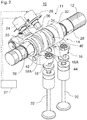
- variable valve train 10 In the FIGS. 1 and 2 a variable valve train 10 is shown.
- the variable valve train 10 has a camshaft 12 and a cam carrier 14.
- the variable valve train 10 has first and second transfer devices 16 and 18 and first and second exhaust valves 20 and 22.
- the variable valve drive 10 has a first actuator 24 and a second actuator 26.
- the cam carrier 14, the transmission devices 16 and 18 and the actuators 24 and 26 form a sliding cam system 11.
- the camshaft 12 is formed as an output camshaft that actuates the output valves 20 and 22.
- the camshaft 12 is part of a dual camshaft system (not shown in detail) that additionally includes an intake camshaft (not shown) for actuating one or more intake valves.
- the camshaft 12 is disposed in common with the intake camshaft as the overhead camshaft.
- DOHC system double overhead camshaft
- the camshaft 12 could also form a so-called SOHC system (single overhead camshaft).
- the camshaft 12 may also be arranged as an underlying camshaft.
- the cam carrier 14 On the camshaft 12 of the cam carrier 14 is arranged rotationally fixed.
- the cam carrier 14 is additionally arranged axially displaceable along a longitudinal axis of the camshaft 12.
- the cam carrier 14 may be axially displaceable between a first stop 28 and a second stop 30.
- the cam carrier 14 has three cams 32, 34 and 36 which are offset from each other in a longitudinal direction of the cam carrier 14 and the camshaft 12.
- the first cam 32 is disposed at a first end of the cam carrier 14 and configured for normal operation, as described in detail later by way of example.
- the second cam 34 is disposed adjacent to the first cam 32 and configured for engine braking operation, as also described in detail later by way of example.
- the third cam 36 is spaced from the second cam 34 and the second end of the cam carrier 14.
- the third cam 36 is designed for normal operation.
- the third cam 36 is shaped like the first cam 32.
- the cam carrier 14 also has a first cam-free section 38 and a second cam-free section 40.
- the first cam-free portion 38 is disposed at the second end of the cam carrier 14.
- the second cam-free portion 40 is disposed between the second cam 34 and the third cam 36.
- a first engagement track (shift gate) 42 extends spirally about a longitudinal axis of the cam carrier 14.
- a second engagement track (shift gate) 44 extends spirally around the longitudinal axis of the cam carrier 14th
- the actuators 24 and 26 For displacing the cam carrier 14 between the stops 28 and 30, the actuators 24 and 26 (FIGS. FIGS. 1 and 2 ) with extendable elements (eg, pin or pin; not shown in detail) selectively engage (mesh in) the engaging tracks 42,44.
- the first actuator 24 may selectively engage the first engagement track 42 for shifting the cam carrier 14 from one axial position to another axial position. In a first axial position of the cam carrier 14 abuts against the second stop 30. In a second axial position of the cam carrier 14 abuts against the first stop 28. In the FIGS. 1 to 4 the cam carrier is shown in the first axial position.
- the second actuator 26 in turn can selectively engage in the second engagement track 44. Then, the cam carrier 14 is shifted from the first axial position to the second axial position.
- the first actuator 24 and the second actuator 26 are controlled by a schematically illustrated control unit 27 (FIG. FIGS. 1 and 2 ).
- the displacement is triggered by the fact that the extended pin of the respective actuator 24, 26 is stationary with respect to an axial direction of the camshaft 12. Consequently, the slidable cam carrier 14 is displaced in a longitudinal direction of the camshaft 12 due to the spiral shape of the engaging tracks 42, 44 when the extended pin is in the respective engagement track 42, 44 engages.
- the pin of the respective actuator 24, 26 is guided by the respective engagement track 42, 44 opposite to the extension direction and thus retracted.
- the pin of the respective actuator 24, 26 is disengaged from the respective engagement track 42, 44th
- the first transmission device 16 and the second transmission device 18 establish an operative connection between the cam carrier 14 and the outlet valves 20, 22.
- the first exhaust valve 20 is operated (opened) when the first cam 32 or the second cam 34 pushes the first transmission device 16 down.
- the second exhaust valve 22 is operated (opened) when the third cam 36 presses the second transmission device 18 down.
- the first transfer device 16 is operatively connected between the first cam 32 and the first exhaust valve 20 via a cam follower 16 A. In other words, the first transfer device 16 is not operatively connected between the second cam 34 in the first axial position of the cam carrier 14 and the first exhaust valve 20.
- the first exhaust valve 20 is operated in accordance with a contour of the first cam 32.
- the first transfer device 16 is operatively connected between the second cam 34 and the first exhaust valve 20 via the cam follower 16A.
- the first exhaust valve 20 is operated in accordance with a contour of the second cam 34.
- the second transmission device 18 In the first axial position of the cam carrier 14, the second transmission device 18 is operatively connected between the third cam 36 and the second exhaust valve 22 via a cam follower 18A.
- the second exhaust valve 22 is operated in accordance with a contour of the third cam 36.
- the second transfer device 18 In the second axial position of the cam carrier 14, the second transfer device 18 does not actuate the second exhaust valve 22.
- the cam follower 18A of the second transmission device 18 is at the same axial position with respect to the camshaft 12 as the first cam-free portion 38.
- the first cam-free portion 38 has no protrusion for actuating the second transmission device 18.
- the second exhaust valve 22 When the cam carrier 14 is in the second axial position, the second exhaust valve 22 is not actuated.
- the first cam-free portion 38 thus has two functions. On the one hand, the first cam-free section 38 receives the first engagement track 42. On the other hand, the first cam-free Section 38 that no actuation of the second exhaust valve 22 in the second axial position of the cam carrier 14 takes place. This functional integration is favorable for space reasons.
- the first transmission device 16 and the second transmission device 18 are each formed as a drag lever.
- the transfer devices 16 and 18 may be formed as rocker arms or plungers.
- the transfer devices 16 and 18 may have, as cam followers 16A, 18A, rotatably mounted rollers.
- the locking device 46 has an elastic element 48 and a blocking body 50.
- the elastic element 48 is arranged in a blind hole of the camshaft 12.
- the elastic member 48 biases the locking body 50 against the cam carrier 14.
- first and second recesses 52 and 54 are arranged.
- the locking body 50 is pressed into the first recess 52 when the cam carrier 14 is in the first axial position.
- the blocking body 50 is pressed into the second recess 54.
- FIG. 5A is a section through the second cam 34 along the line BB in FIG. 4 shown.
- the second cam 34 has a first base circle area 34A and a second base circle area 34C.
- the base circle areas 34A, 34C are separated on the one hand by a first valve lift area 34B and on the other hand by a second valve lift area 34D.
- the second valve lift area 34D has a boundary portion 34E that directly adjoins the first base circle area 34A.
- the boundary portion 34E forms an outgoing edge (ramp) of the second cam 34.
- FIG. 5B is a section through the first cam 32 along the line CC in FIG. 4 shown.
- the first cam 32 has a base circle portion 32A and a valve lift portion 32B.
- the valve lift portion 32B has a boundary portion 32C which is directly adjacent to the base circle portion 32A.
- the boundary portion 32C forms an outgoing edge (ramp) of the first cam 32.
- the boundary portion 32C of the first cam 32 and the boundary portion 34E of the second cam 34 are formed the same.
- the boundary portion 32C of the first cam 32 and the Boundary portion 34E of the second cam 34 is disposed at a same circumferential position with respect to a longitudinal axis of the camshaft 12.
- the boundary sections 32C, 34E form a common planar ramp.
- the boundary portions 32C, 34E allow axial displacement of the cam carrier 14 to take place not only in the base circle region 32A, 34A, but additionally in the boundary portion 32C, 34E.
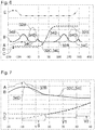
- FIG. 6 different curves A to E are shown in a path camshaft angle diagram.
- FIG. 7 is an enlargement of a section of the diagram of FIG. 6 represented, in particular, the boundary portions 32C, 34E are shown.
- a dotted curve A indicates a valve lift of the exhaust valve 20 in accordance with a normal operation as effected by the first cam 32.
- the curve A thus corresponds to a rolled-off cam profile of the first cam 32.
- the exhaust valve 20 is opened during the exhaust stroke (exhaust stroke) for expelling exhaust gas through the valve lift region 32B.
- the exhaust valve 20 remains closed due to the base circle portion 32A of the first cam 32.
- a solid curve B indicates a valve lift of the exhaust valve 20 in accordance with an engine braking operation as effected by the second cam 34.
- the curve B thus corresponds to a rolled-off cam profile of the second cam 34.
- the exhaust valve 20 is slightly opened by the first valve lift region 34B at the end of the compression stroke in the region of top dead center at about 60 ° CA to 100 ° CA before top dead center. This is in FIG. 6 each at around -225 ° NW (camshaft angle) and at around 135 ° NW.
- the exhaust valve 20 is further opened by the valve lift 34B and closes at the end of the expansion stroke approximately at bottom dead center.
- the opening of the exhaust valve 20 at the end of the compression stroke causes the compressed air in the cylinder to be pushed through the open exhaust valve 20 into the exhaust system through the piston moving toward top dead center.
- the compression work previously done brakes the crankshaft and thus the internal combustion engine.
- the open exhaust valve 20 during the expansion stroke causes air from the exhaust pipes to be drawn back into the cylinder.
- the cylinder is substantially filled with air from the exhaust system.
- the exhaust valve 20 may first be closed by the second base circle portion 34C being held.
- the exhaust valve 20 opens in the region of top dead center through the second valve lift 34D.
- the opening is again at about 60 ° CA to 100 ° CA before top dead center. This is in FIG. 6 each shown at around -45 ° NW and around 315 ° NW.
- the closed exhaust valve 20 during the first portion of the exhaust stroke causes the air sucked in the expansion stroke to be compressed by performing work.
- the cylinder pressure increases.
- the compression work brakes the crankshaft and thus the internal combustion engine.
- the opening of the exhaust valve 20 to the end of the Ausschiebetaktes causes the air is pushed through the open exhaust valve 20 into the exhaust system.
- the cylinder is again filled with air through the or the open intake valves. The cycle starts again.
- the use of the second cam 34 to control the exhaust valve 20 results in a double compression followed by a decompression so that engine braking functionality is ensured.
- the first cam 32 and the second cam 34 are fitted to each other so that the boundary portion 32C of the first cam 32 and the boundary portion 34E of the second cam 34 are formed identically.
- This allows an axial displacement of the cam carrier 14 to be practicable not only within the base circle regions 32A, 34A. Instead, the axial displacement may additionally occur while the cam follower 16A is operatively connected to one of the boundary portions 32C, 34E. This allows the axial displacement to start earlier. This can be understood from the curves C, D and E.
- the dash-dotted curve C refers to a movement of the movable pin of one of the actuators 24 or 26 with respect to the cam carrier 14.
- the dashed curve D refers to a movement of the respective engagement track 42 or 44 and thus of the cam carrier 14 along the longitudinal axis of the camshaft 12th
- the double-dashed curve E shows a profile of a depth contour of the respective engagement track 42 or 44 (only in FIG FIG. 6 shown).
- an axial displacement of the cam carrier 14 at the first axial position is described to the second axial position.
- An axial displacement of the cam carrier 14 from the second axial position to the first axial position takes place analogously.
- the movable pin of the first actuator 24 is extended in the direction of the first engagement track 42 and spurts into the first engagement track 42.
- the Einspuren is through the trained deep contour of the first engagement track 42 allows (see curve E).
- the cross-sectional constriction of the first engagement track 42 results in a reduction in play between the pin of the first actuator 24 and the first engagement track 24.
- the clearance reduction takes place in a region S (see FIG FIG. 7 ).
- the area S is reached by the pin of the first actuator 24 and passed through before the cam follower 16 A reaches the boundary portion 32 C of the first cam 32.
- the axial displacement of the cam carrier 14 thus also takes place outside the base circle regions 32A, 34A in the boundary section 32C of the first cam 32 and the boundary section 34E of the second cam 34.
- This increases the time range for the axial displacement of the cam carrier 14. Due to the enlarged displacement range, the accelerations and thus the mass forces at the same switching speed for the axial displacement of the cam carrier 14 can be reduced. On the one hand, this can be used to increase the functional reliability and service life due to lower forces and pressure. On the other hand, this can be used to increase the maximum switching speed of the system.
- the additional displacement range V1 which is made possible by the identically formed boundary portions 32C, 34E, extends over approximately 22 ° camshaft angle.
- the cam-free portion 38 which serves both as a zero cam and also provided with the second engagement track 42, with an additional axial tolerance range (clearance range).
- the adjacent cam 36 is made correspondingly narrower.
- sliding cam system described herein is not limited to the application described herein.
- a similar design of the starting areas (inlet areas) of the cams can be provided for realizing the identically formed border sections.
- variable valve trains for intake valves of an internal combustion engine For example, a start-up area of a first cam for normal operation may be made identical to a start-up area of a second cam for miller operation and positioned at the same circumferential position with respect to the longitudinal axis of the camshaft.
- the displacement device first actuator, second actuator, first engagement track, second engagement track
- a method of operating an internal combustion engine with any cam carrier displacement device may include displacing the cam carrier while the cam follower is in contact with the boundary region (s).
- axial displacement may begin and / or end when the cam follower is in contact with a boundary region.
Landscapes
- Engineering & Computer Science (AREA)
- Mechanical Engineering (AREA)
- General Engineering & Computer Science (AREA)
- Chemical & Material Sciences (AREA)
- Combustion & Propulsion (AREA)
- Valve Device For Special Equipments (AREA)
Abstract
Description
- Die Erfindung betrifft ein Schiebenockensystem für einen variablen Ventiltrieb, einen variablen Ventiltrieb, ein Kraftfahrzeug und ein Verfahren zum Betreiben eines Verbrennungsmotors.
- Ventilgesteuerte Brennkraftmaschinen weisen eines oder mehrere steuerbare Ein- und Auslassventile je Zylinder auf. Variable Ventilsteuerungen ermöglichen ein flexibles Ansteuern der Ventile zum Verändern der Öffnungszeit, Schließzeit und/oder des Ventilhubs. Dadurch kann der Motorbetrieb beispielsweise an eine spezifische Lastsituation angepasst werden.
- Aus der
DE 196 11 641 C1 ist ein Ventiltrieb bekannt, mit dem die Betätigung eines Gaswechselventils mit mehreren unterschiedlichen Hubkurven ermöglicht wird. Hierzu ist auf der Nockenwelle ein Schiebenocken mit mindestens einem, mehrere Nockenbahnen aufweisenden Nockenabschnitt drehfest aber axial verschieblich gelagert, der eine Hubkontur aufweist, in die ein Aktuator in Form eines Stifts von radial außen zur Erzeugung einer axialen Verschiebung des Schiebenockens eingeführt wird. Durch die axiale Verschiebung des Schiebenockens wird beim jeweiligen Gaswechselventil ein unterschiedlicher Ventilhub eingestellt. Der Schiebenocken wird nach der axialen Verschiebung desselben relativ zur Nockenwellen dadurch in seiner axialen Relativposition auf der Nockenwelle rastiert, dass abhängig von der axialen Relativposition mindestens eine federbeaufschlagte Rastkugel, die in der Nockenwelle aufgenommen und gelagert ist, in mindestens eine Rastnut eingreift. Die axiale Verschiebung des Schiebenockens zur Veränderung des Ventilhubs erfolgt ausschließlich im sogenannten Grundkreis des oder jedes Nockenabschnitts bzw. der Nockenbahnen desselben. Hierdurch wird die Schaltdrehzahl des Ventiltriebs beschränkt. - Je kürzer die miteinander übereinstimmenden Grundkreise der Nocken sind, desto weniger Zeit steht zum axialen Verschieben des Schiebenockens zur Verfügung. Umso weniger Zeit zum axialen Verschieben des Schiebenockensystem Verfügung steht, desto steiler muss die Rampe der Schaltkulisse (Eingriffsspur) ausgeführt werden. Beim axialen Verschieben des Schiebenockens können teilweise erhebliche Kräfte beim Kontakt zwischen dem Stift des Aktuators und der Schaltkulisse auftreten. Insbesondere bei steilen Rampen können besonders große Kräfte auftreten, die eine Lebensdauer des Schiebenockensystems negativ beeinflussen können und/oder eine maximale Schaltdrehzahl begrenzen.
- Aus der
DE 10 2012 112 482 A1 ist ein Verfahren zum Betreiben einer Brennkraftmaschine mit mehreren Zylindern offenbart. Die Brennkraftmaschine weist zur Betätigung von Gaswechselventilen einen Ventiltrieb mit mindestens einer drehbar gelagerten Nockenwelle und mit mindestens einem auf der jeweiligen Nockenwelle axial verschiebbaren Schiebenocken auf. Der jeweilige Schiebenocken weist mindestens einen Kulissenabschnitt mit mindestens einer an einer äußeren Mantelfläche des jeweiligen Kulissenabschnitts ausgebildeten Nut auf, wobei der jeweilige Schiebenocken mindestens einen Nockenabschnitt mit mehreren Nockenbahnen zur Einstellung unterschiedlicher Ventilhübe aufweist. Zur Bewirkung einer axialen Verschiebung des jeweiligen Schiebenockens wird ein betätigbarer Stift eines Aktuators von radial außen in eine Nut des Kulissenabschnitts eingeführt. Die axiale Verschiebung des jeweiligen Schiebenockens wird abhängig von der axialen Verschieberichtung desselben und/oder abhängig von einem Ventilspiel außerhalb eines Grundkreises des oder jedes Nockenabschnitts desselben durchgeführt. - Der Erfindung liegt die Aufgabe zu Grunde, ein alternatives oder verbessertes Schiebenockensystem und Verfahren zum Betreiben eines Verbrennungsmotors zu schaffen, bei der die auftretenden Kräfte während des Verschiebevorgangs des Nockenträgers im Vergleich zu herkömmlichen Systemen verringert werden.
- Die Aufgabe wird gelöst durch ein Schiebenockensystem und ein Verfahren gemäß den unabhängigen Ansprüchen. Vorteilhafte Weiterbildungen sind in den abhängigen Ansprüchen und der Beschreibung angegeben.
- Das Schiebenockensystem ist für einen variablen Ventiltrieb eines Verbrennungsmotors eines Kraftfahrzeugs, insbesondere Nutzfahrzeugs, ausgebildet. Das Schiebenockensystem weist eine Nockenwelle und einen Nockenträger auf. Der Nockenträger ist auf der Nockenwelle drehfest und axial verschiebbar zwischen einer ersten Axialposition und einer zweiten Axialposition angeordnet und weist einen ersten Nocken, einen zweiten Nocken und eine erste Eingriffsspur zum axialen Verschieben des Nockenträgers auf. Das Schiebenockensystem weist einen Nockenfolger, der in der ersten Axialposition des Nockenträgers in Wirkverbindung mit dem ersten Nocken steht und in der zweiten Axialposition des Nockenträgers in Wirkverbindung mit dem zweiten Nocken steht, auf. Das Schiebenockensystem weist einen ersten Aktor, der ein ein- und ausfahrbares Element, insbesondere einen Stift, zum Einspuren in die erste Eingriffsspur zum axialen Verschieben des Nockenträgers aufweist, auf. Der erste Nocken und der zweite Nocken sind entlang einer Längsachse der Nockenwelle versetzt zueinander angeordnet. Der erste Nocken weist einen Grundkreisbereich und einen Ventilhubbereich mit einem Grenzabschnitt, der an den Grundkreisbereich des ersten Nockens angrenzt, auf. Der zweite Nocken weist einen Grundkreisbereich und einen Ventilhubbereich mit einem Grenzabschnitt, der an den Grundkreisbereich des zweiten Nockens angrenzt, auf. Der Grenzabschnitt des ersten Nockens und der Grenzabschnitt des zweiten Nockens sind gleich ausgebildet und an einer gleichen Umfangsposition um die Längsachse der Nockenwelle angeordnet. Der erste Aktor, der Nockenfolger und die erste Eingriffsspur sind so angeordnet und ausgebildet, dass eine Axialverschiebung des Nockenträgers durchführbar ist, während der Nockenfolger in Wirkverbindung mit dem Grenzabschnitt des ersten Nockens und/oder dem Grenzabschnitt des zweiten Nockens steht.
- Das Schiebenockensystem ermöglicht eine Verlängerung der zur Verfügung stehenden Zeitspanne zum axialen Verschieben des Nockenträgers durch Ausdehnung in die Grenzabschnitte der Nocken. Aufgrund des größeren Schaltbereichs können die Beschleunigungen und somit die Massenkräfte bei gleicher Schaltdrehzahl für die axiale Verschiebung reduziert werden. Einerseits kann dies beispielsweise dazu genutzt werden, um die Funktionssicherheit und Lebensdauer aufgrund geringerer Kräfte und Pressungen zu erhöhen. Andererseits kann dies beispielsweise dazu genutzt werden, um die maximale Schaltdrehzahl des Systems zu erhöhen.
- Insbesondere kann der erste Nocken direkt angrenzend an den zweiten Nocken ausgebildet sein.
- In einem besonders bevorzugten Ausführungsform sind der erste Aktor, der Nockenfolger und die erste Eingriffsspur so angeordnet und ausgebildet, dass eine Axialverschiebung des Nockenträgers beginnt und/oder endet, während der Nockenfolger in Wirkverbindung mit dem Grenzabschnitt des ersten Nockens oder dem Grenzabschnitt des zweiten Nockens steht. Damit kann insbesondere der Beginn und/oder das Ende der axialen Verschiebung des Nockenträgers in die Grenzbereiche verlagert werden. Somit kann die zur Verfügung stehende Zeitdauer zum axialen Verschieben des Nockenträgers verlängert werden.
- In einer Ausführungsform erstrecken sich die Grenzabschnitte über einen Bereich größer oder gleich 1° Nockenwellenwinkel.
- In einer Weiterbildung erstrecken sich die Grenzabschnitte über einen Bereich zwischen 5° und 45° Nockenwellenwinkel, insbesondere zwischen 15° und 30° Nockenwellenwinkel.
- In einer weiteren Ausführungsform bilden die Grenzabschnitte eine gemeinsame flächige Rampe.
- In einer Ausführungsvariante sind die Grenzabschnitte in einem Auslaufbereich des ersten und zweiten Nockens angeordnet. Alternativ oder zusätzlich beginnt die Axialverschiebung des Nockenträgers, wenn der Nockenfolger in Wirkverbindung mit dem Grenzabschnitt des ersten Nockens oder des zweiten Nockens steht. Vorzugsweise endet die axiale Verschiebung, während der Nockenfolger in Wirkverbindung mit dem Grundkreisbereich des ersten Nockens oder des zweiten Nockens steht. Es ist allerdings auch möglich, dass die axiale Verschiebung erst in einem weiteren Grenzabschnitt in einem Einlaufbereich des ersten oder zweiten Nockens endet, wobei die weiteren Grenzabschnitte des ersten und zweiten Nockens wiederum gleich ausgebildet und an einer gleichen Umfangsposition um die Längsachse der Nockenwelle angeordnet sind.
- In einer weiteren Ausführungsvariante sind die Grenzabschnitte in einem Einlaufbereich des ersten und zweiten Nockens angeordnet. Alternativ oder zusätzlich endet die Axialverschiebung des Nockenträgers, wenn der Nockenfolger in Wirkverbindung mit dem Grenzabschnitt des ersten Nockens oder des zweiten Nockens steht. Vorzugsweise beginnt die axiale Verschiebung des Nockenträgers während der Nockenfolger in Wirkverbindung mit dem Grundkreisbereich des ersten Nockens oder des zweiten Nockens steht. Es ist allerdings auch möglich, die die axiale Verschiebung bereits in einem anderen Grenzabschnitt in einem Auslaufbereich des ersten oder zweiten Nockens beginnt, wobei die anderen Grenzabschnitte des ersten und zweiten Nockens wiederum gleich ausgebildet und an einer gleichen Umfangsposition um die Längsachse der Nockenwelle angeordnet sind.
- In einem Ausführungsbeispiel weist der Nockenträger eine zweite Eingriffsspur zum axialen Verschieben des Nockenträgers in einer Richtung entgegengesetzt zu einer von der ersten Eingriffsspur bewirkten axialen Verschiebung auf. Das Schiebenockensystem weist ferner einen zweiten Aktor auf, der ein ein- und ausfahrbares Element, insbesondere einen Stift, zum Einspuren in die zweite Eingriffsspur zum axialen Verschieben des Nockenträgers aufweist. Der zweite Aktor, der Nockenfolger und die zweite Eingriffsspur sind so angeordnet und ausgebildet, dass eine Axialverschiebung des Nockenträgers durchführbar ist (insbesondere beginnt und/oder endet), während der Nockenfolger in Wirkverbindung mit dem Grenzabschnitt des ersten Nockens oder dem Grenzabschnitt des zweiten Nockens steht.
- Insbesondere können der erste Aktor und der zweite Aktor separat voneinander vorgesehen sein. Es ist allerdings auch möglich, dass der erste Aktor und der zweite Aktor in einem gemeinsamen Gehäuse vorgesehen sind.
- Vorzugsweise können die erste Eingriffsspur und die zweite Eingriffsspur separat voneinander vorgesehen sein. Es ist allerdings auch möglich, dass die erste Eingriffsspur und die zweite Eingriffsspur in einem gleichen Bereich des Nockenträgers angeordnet sind. Bevorzugt können sich die erste Eingriffsspur und die zweite Eingriffsspur kreuzen.
- In einem weiteren Ausführungsbeispiel weist die erste Eingriffsspur eine Querschnittsverengung zur Spielreduzierung zwischen der ersten Eingriffsspur und dem ein- und ausfahrbaren Element des ersten Aktors beim Einspuren (des ausgefahrenen Elements in die erste Eingriffsspur) auf. Die Querschnittsverengung ist so angeordnet, dass die Spielreduzierung stattfindet, bevor der Nockenfolger in Wirkverbindung mit dem Grenzabschnitt des ersten Nockens oder des zweiten Nockens gelangt. Damit verkürzt der für die Spielreduzierung vorgesehene Abschnitt der Eingriffsspur den für die axiale Verschiebung des Nockenträgers vorgesehenen Abschnitt der Eingriffsspur nicht.
- Zum Erzielen der gleichen Vorteile ist es auch möglich, dass die zweite Eingriffsspur eine Querschnittsverengung zur Spielreduzierung zwischen der zweiten Eingriffsspur und dem ein- und ausfahrbaren Element des zweiten Aktors beim Einspuren (des ausgefahrenen Elements in die zweite Eingriffsspur) aufweist. Die Querschnittsverengung ist so angeordnet, dass die Spielreduzierung stattfindet, bevor der Nockenfolger in Wirkverbindung mit dem Grenzabschnitt des ersten Nockens oder des zweiten Nockens gelangt.
- In einer besonders bevorzugten Ausführungsform erstreckt sich die erste Eingriffsspur und/oder die zweite Eingriffsspur spiralförmig um die Längsachse der Nockenwelle.
- In einer weiteren Ausführungsform ist das ein- und ausfahrbare Element des ersten Aktors und/oder des zweiten Aktors radial bezüglich der Längsachse der Nockenwelle bewegbar.
- Die Erfindung betrifft auch einen variablen Ventiltrieb für einen Verbrennungsmotor. Der variable Ventiltrieb weist ein Schiebenockensystem wie hierin offenbart auf. Der variable Ventiltrieb weist ein Gaswechselventil, insbesondere ein Einlassventil oder ein Auslassventil, das in Wirkverbindung mit dem Nockenfolger steht, auf. Der erste Nocken und der zweite Nocken bewirken unterschiedliche Ventilhübe, Öffnungszeiten und/oder Schließzeiten des Gaswechselventils.
- In einer Weiterbildung ist das Gaswechselventil ein Auslassventil. Der erste Nocken ist für einen Normalbetrieb des Verbrennungsmotors ausgebildet, bei dem der erste Nocken das Auslassventil im Ausschubtakt offen hält. Der zweite Nocken ist für einen Motorbremsbetrieb des Verbrennungsmotors ausgebildet, bei dem, vorzugsweise, das Auslassventil im Verdichtungstakt und im Ausschubtakt zunächst geschlossen gehalten und vor Erreichen eines oberen Totpunkts einer Kolbenbewegung geöffnet wird.
- In einem bevorzugten Ausführungsbeispiel ist der zweite Nocken so ausgebildet, dass das Auslassventil zwischen 100° KW und 60° KW (Kurbelwellenwinkel) vor dem Erreichen des oberen Totpunkts öffnet. Alternativ oder zusätzlich ist der zweite Nocken so ausgebildet, dass das Auslassventil nach dem Öffnen im Ausschubtakt im Bereich zwischen dem oberem Totpunkt und 30° KW nach dem oberen Totpunkt schließt. Alternativ oder zusätzlich ist der zweite Nocken so ausgebildet, dass das Auslassventil nach dem Öffnen im Verdichtungstakt im Bereich zwischen dem unteren Totpunkt und 30° KW nach dem unteren Totpunkt schließt.
- Die Erfindung betrifft auch ein Kraftfahrzeug, insbesondere Nutzfahrzeug (zum Beispiel Lastkraftwagen oder Omnibus), aufweisend den variablen Ventiltrieb wie hierin offenbart oder das Schiebenockensystem wie hierin offenbart.
- Die Erfindung betrifft auch ein Verfahren zum Betreiben eines Verbrennungsmotors mit einem Schiebenockensystem. Das Schiebenockensystem weist einen auf einer Nockenwelle drehfest angeordneten und axial verschiebbaren Nockenträger mit einem ersten Nocken und einem zweiten Nocken auf. Der erste Nocken und der zweite Nocken weisen jeweils einen Grundkreisbereich und einen Ventilhubbereich mit einem Grenzabschnitt, der angrenzend an den jeweiligen Grundkreisbereich angeordnet ist, auf. Der Grenzabschnitt des ersten Nockens und der Grenzabschnitt des zweiten Nockens sind gleich ausgebildet und an einer gleichen Umfangsposition um eine Längsachse der Nockenwelle angeordnet. Das Schiebenockensystem weist einen Nockenfolger, der wahlweise in Wirkverbindung mit dem ersten Nocken oder dem zweiten Nocken steht, auf. Das Verfahren weist das axiale Verschieben des Nockenträgers auf, wobei das axiale Verschieben des Nockenträgers durchgeführt wird, insbesondere beginnt oder endet, während der Nockenfolger in Wirkverbindung mit dem Grenzabschnitt des ersten Nockens und/oder des zweiten Nockens steht.
- Das Verfahren bietet die gleichen Vorteile wie das hierin offenbarte Schiebenockensystem. Zusätzlich weist das Verfahren eine höhere Flexibilität auf, da es nicht auf die axiale Verschiebung des Nockenträgers mittels der Aktoren und Eingriffsspuren wie hierin offenabrt beschränkt ist.
- Insbesondere kann das Verfahren das hierin offenbarte Schiebenockensystem vorzugsweise mit radial ein- und ausfahrbaren Elementen von Aktoren, die in spiralförmige Eingriffspuren eingreifen, zum axialen Verschieben des Nockenträgers verwenden. Es ist allerdings auch möglich, dass das Verfahren ein anderes Verschiebesystem zum axialen Verschieben des Nockenträgers verwendet.
- In einer bevorzugten Ausführungsform beginnt das axiale Verschieben des Nockenträgers, während der Nockenfolger in Wirkverbindung mit dem Grenzabschnitt des ersten Nockens oder des zweiten Nockens steht, und/oder endet, während der Nockenfolger in Wirkverbindung mit dem Grundkreisbereich des ersten Nockens oder des zweiten Nockens steht.
- Alternativ oder zusätzlich beginnt das axiale Verschieben des Nockenträgers, während der Nockenfolger in Wirkverbindung mit dem Grundkreisbereich des ersten Nockens oder des zweiten Nockens steht, und/oder endet, während der Nockenfolger in Wirkverbindung mit dem Grenzabschnitt des ersten Nockens oder des zweiten Nockens steht.
- Die zuvor beschriebenen bevorzugten Ausführungsformen und Merkmale der Erfindung sind beliebig miteinander kombinierbar. Weitere Einzelheiten und Vorteile der Erfindung werden im Folgenden unter Bezug auf die beigefügten Zeichnungen beschrieben. Es zeigen:
- Figur 1
- eine perspektivische Ansicht eines beispielhaften variablen Ventiltriebs;
- Figur 2
- eine weitere perspektivische Ansicht des beispielhaften variablen Ventiltriebs;
- Figur 3
- eine Draufsicht auf eine Nockenwelle des beispielhaften variablen Ventiltriebs;
- Figur 4
- eine Längsschnittansicht der Nockenwelle von
Figur 3 entlang der Linie A-A; - Figur 5A
- eine erste Querschnittansicht der Nockenwelle von
Figur 4 entlang der Linie B-B; - Figur 5B
- eine zweite Querschnittansicht der Nockenwelle von
Figur 4 entlang der Linie C-C; - Figur 6
- ein Weg-Nockenwellenwinkel-Diagramm; und
- Figur 7
- eine Vergrößerung eines Bereichs des Weg-Nockenwellenwinkel-Diagramms von
Figur 6 . - Die in den Figuren gezeigten Ausführungsformen stimmen zumindest teilweise überein, so dass ähnliche oder identische Teile mit den gleichen Bezugszeichen versehen sind und zu deren Erläuterung auch auf die Beschreibung der anderen Ausführungsformen bzw. Figuren verwiesen wird, um Wiederholungen zu vermeiden.
- Nachfolgend ist unter Bezugnahme auf
Figur 1 bis Figur 4 zunächst ein variabler Ventiltrieb mit Schiebenockensystem beschrieben. Das Schiebenockensystem ermöglicht eine Umschaltung zwischen verschiedenen Ventilsteuerkurven der betätigten Gaswechselventile. Das hierin beispielhaft offenbarte System bezieht sich auf die Betätigung von Auslassventilen eines Verbrennungsmotors. Die hierin offenbarten Prinzipien sind jedoch auch bei einem variablen Ventiltrieb für ein oder mehrere Einlassventile anwendbar. - In den
Figuren 1 und2 ist ein variabler Ventiltrieb 10 gezeigt. Der variable Ventiltrieb 10 weist eine Nockenwelle 12 und einen Nockenträger 14 auf. Zusätzlich weist der variable Ventiltrieb 10 eine erste und zweite Übertragungsvorrichtung 16 und 18 sowie ein erstes und zweites Auslassventil 20 und 22 auf. Zudem weist der variable Ventiltrieb 10 einen ersten Aktor 24 und einen zweiten Aktor 26 auf. Der Nockenträger 14, die Übertragungsvorrichtungen 16 und 18 sowie die Aktoren 24 und 26 bilden ein Schiebenockensystem 11. - Die Nockenwelle 12 ist als eine Ausgangsnockenwelle ausgebildet, die die Ausgangsventile 20 und 22 betätigt. Die Nockenwelle 12 ist Teil eines Doppelnockenwellensystems (nicht im Detail dargestellt), das zusätzlich eine Einlassnockenwelle (nicht dargestellt) zur Betätigung von einem oder mehreren Einlassventilen aufweist. Die Nockenwelle 12 ist gemeinsam mit der Einlassnockenwelle als obenliegende Nockenwelle angeordnet. Die Nockenwelle 12 und die Einlassnockenwelle bilden somit ein sogenanntes DOHC-System (engl. double overhead camshaft). Alternativ könnte die Nockenwelle 12 auch ein sogenanntes SOHC-System bilden (engl. single overhead camshaft). In anderen Ausführungsformen kann die Nockenwelle 12 auch als untenliegende Nockenwelle angeordnet sein.
- Auf der Nockenwelle 12 ist der Nockenträger 14 drehfest angeordnet. Der Nockenträger 14 ist zusätzlich axial verschiebbar entlang einer Längsachse der Nockenwelle 12 angeordnet. Der Nockenträger 14 kann zwischen einem ersten Anschlag 28 und einem zweiten Anschlag 30 axial verschiebbar sein.
- Unter Bezugnahme auf die
Figuren 1 bis 4 ist nachfolgend der Nockenträger 14 beschrieben. Der Nockenträger 14 weist drei Nocken 32, 34 und 36 auf, die in einer Längsrichtung des Nockenträgers 14 und der Nockenwelle 12 voneinander versetzt sind. Der erste Nocken 32 ist an einem ersten Ende des Nockenträgers 14 angeordnet und für einen Normalbetrieb ausgebildet, wie später beispielhaft im Detail beschrieben. Der zweite Nocken 34 ist angrenzend an den ersten Nocken 32 angeordnet und für einen Motorbremsbetrieb ausgebildet, wie später ebenfalls beispielhaft im Detail beschrieben. Der dritte Nocken 36 ist beabstandet zu dem zweiten Nocken 34 und dem zweiten Ende des Nockenträgers 14 angeordnet. Der dritte Nocken 36 ist für den Normalbetrieb ausgebildet. Der dritte Nocken 36 ist wie der ersten Nocken 32 geformt. - Der Nockenträger 14 weist zudem einen ersten nockenfreien Abschnitt 38 und einen zweiten nockenfreien Abschnitt 40 auf. Der erste nockenfreie Abschnitt 38 ist am zweiten Ende des Nockenträgers 14 angeordnet. Der zweite nockenfreie Abschnitt 40 ist zwischen dem zweiten Nocken 34 und dem dritten Nocken 36 angeordnet. Im ersten nockenfreien Abschnitt 38 erstreckt sich eine erste Eingriffsspur (Schaltkulisse) 42 spiralförmig um eine Längsachse des Nockenträgers 14. Im zweiten nockenfreien Abschnitt 40 erstreckt sich eine zweite Eingriffsspur (Schaltkulisse) 44 spiralförmig um die Längsachse des Nockenträgers 14.
- Zum Verschieben des Nockenträgers 14 zwischen den Anschlägen 28 und 30 können die Aktoren 24 und 26 (
Figuren 1 und2 ) mit ausfahrbaren Elementen (z.B. Stift oder Pin; nicht im Detail gezeigt) selektiv in die Eingriffsspuren 42, 44 eingreifen (einspuren). Im Einzelnen kann der erste Aktor 24 selektiv in die erste Eingriffsspur 42 zum Verschieben des Nockenträgers 14 von einer Axialposition zu einer anderen Axialposition eingreifen. In einer ersten Axialposition liegt der Nockenträger 14 an dem zweiten Anschlag 30 an. In einer zweiten Axialposition liegt der Nockenträger 14 an dem ersten Anschlag 28 an. In denFiguren 1 bis 4 ist der Nockenträger in der ersten Axialposition dargestellt. Der zweite Aktor 26 wiederum kann selektiv in die zweite Eingriffsspur 44 eingreifen. Dann wird der Nockenträger 14 von der ersten Axialposition zu der zweiten Axialposition verschoben. Der erste Aktor 24 und der zweite Aktor 26 werden von einer schematisch dargestellten Steuereinheit 27 (Figuren 1 und2 ) angesteuert. - Die Verschiebung wird dadurch ausgelöst, dass der ausgefahrene Stift des jeweiligen Aktors 24, 26 bezüglich einer Axialrichtung der Nockenwelle 12 ortsfest ist. Folglich wird der verschiebbare Nockenträger 14 aufgrund der Spiralform der Eingriffsspuren 42, 44 in einer Längsrichtung der Nockenwelle 12 verschoben, wenn der ausgefahrene Stift in die jeweilige Eingriffsspur 42, 44 eingreift. Am Ende des Verschiebevorgangs wird der Stift des jeweiligen Aktors 24, 26 von der jeweiligen Eingriffsspur 42, 44 entgegengesetzt zu der Ausfahrrichtung geführt und somit eingefahren. Der Stift des jeweiligen Aktors 24, 26 gelangt außer Eingriff mit der jeweiligen Eingriffsspur 42, 44.
- Die erste Übertragungsvorrichtung 16 und die zweite Übertragungsvorrichtung 18 (
Figuren 1 und2 ) stellen eine Wirkverbindung zwischen dem Nockenträger 14 und den Auslassventilen 20, 22 her. Das erste Auslassventil 20 wird betätigt (geöffnet), wenn der erste Nocken 32 oder der zweite Nocken 34 die erste Übertragungsvorrichtung 16 nach unten drückt. Das zweite Auslassventil 22 wird betätigt (geöffnet) wenn der dritte Nocken 36 die zweite Übertragungsvorrichtung 18 nach unten drückt. - Befindet sich der Nockenträger 14 in der ersten Axialposition (wie in den
Figuren 1 bis 4 gezeigt), ist die erste Übertragungsvorrichtung 16 über einen Nockenfolger 16A in Wirkverbindung zwischen dem ersten Nocken 32 und dem ersten Auslassventil 20. Mit anderen Worten gesagt, ist die erste Übertragungsvorrichtung 16 in der ersten Axialposition des Nockenträgers 14 nicht in Wirkverbindung zwischen dem zweiten Nocken 34 und dem ersten Auslassventil 20. Das erste Auslassventil 20 wird gemäß einer Kontur des ersten Nockens 32 betätigt. In der zweiten Axialposition des Nockenträgers 14 ist die erste Übertragungsvorrichtung 16 über den Nockenfolger 16A in Wirkverbindung zwischen dem zweiten Nocken 34 und dem ersten Auslassventil 20. Das erste Auslassventil 20 wird gemäß einer Kontur des zweiten Nockens 34 betätigt. - In der ersten Axialposition des Nockenträgers 14 ist die zweite Übertragungsvorrichtung 18 über einen Nockenfolger 18A in Wirkverbindung zwischen dem dritten Nocken 36 und dem zweiten Auslassventil 22. Das zweite Auslassventil 22 wird gemäß einer Kontur des dritten Nockens 36 betätigt. In der zweiten Axialposition des Nockenträgers 14 betätigt die zweite Übertragungsvorrichtung 18 das zweite Auslassventil 22 nicht. In der zweiten Axialposition des Nockenträgers 14 liegt der Nockenfolger 18A der zweiten Übertragungsvorrichtung 18 an der gleichen Axialposition bezüglich der Nockenwelle 12 wie der erste nockenfreie Abschnitt 38. Der erste nockenfreie Abschnitt 38 weist keine Erhebung zum Betätigen der zweiten Übertragungsvorrichtung 18 auf. Ist der Nockenträger 14 in der zweiten Axialposition, wird das zweite Auslassventil 22 nicht betätigt.
- Der erste nockenfreie Abschnitt 38 hat somit zwei Funktionen. Einerseits nimmt der erste nockenfreie Abschnitt 38 die erste Eingriffsspur 42 auf. Andererseits dient der erste nockenfreie Abschnitt 38 dazu, dass keine Betätigung des zweiten Auslassventils 22 in der zweiten Axialposition des Nockenträgers 14 erfolgt. Diese Funktionsintegration ist aus Bauraumgründen günstig.
- In der dargestellten Ausführungsform sind die erste Übertragungsvorrichtung 16 und die zweite Übertragungsvorrichtung 18 jeweils als ein Schlepphebel ausgebildet. In anderen Ausführungsformen können die Übertragungsvorrichtungen 16 und 18 als Kipphebel oder Stößel ausgebildet sein. In einigen Ausführungsformen können die Übertragungsvorrichtungen 16 und 18 als Nockenfolger 16A, 18A beispielsweise drehbar gelagerte Rollen aufweisen.
- Unter Bezugnahme auf
Figur 4 ist eine Arretierungsvorrichtung 46 gezeigt. Die Arretierungsvorrichtung 46 weist ein elastisches Element 48 und einen Sperrkörper 50 auf. Das elastische Element 48 ist in einem Sackloch der Nockenwelle 12 angeordnet. Das elastische Element 48 spannt den Sperrkörper 50 gegen den Nockenträger 14 vor. In einer Innenumfangsfläche des Nockenträgers 14 sind eine erste und zweite Ausnehmung 52 und 54 angeordnet. Zum Arretieren des Nockenträgers 14 wird der Sperrkörper 50 in die erste Ausnehmung 52 gedrückt, wenn der Nockenträger 14 in der ersten Axialposition ist. In der zweiten Axialposition des Nockenträgers 14 wird der Sperrkörper 50 in die zweite Ausnehmung 54 gedrückt. - In
Figur 5A ist ein Schnitt durch den zweiten Nocken 34 entlang der Linie B-B inFigur 4 dargestellt. Der zweite Nocken 34 weist einen ersten Grundkreisbereich 34A und einen zweiten Grundkreisbereich 34C auf. Die Grundkreisbereiche 34A, 34C sind einerseits durch einen ersten Ventilhubbereich 34B und andererseits durch einen zweiten Ventilhubbereich 34D voneinander getrennt. Der zweite Ventilhubbereich 34D weist einen Grenzabschnitt 34E auf, der direkt an den ersten Grundkreisbereich 34A angrenzt. Der Grenzabschnitt 34E bildet eine auslaufende Flanke (Rampe) des zweiten Nockens 34. - In
Figur 5B ist ein Schnitt durch den ersten Nocken 32 entlang der Linie C-C inFigur 4 dargestellt. Der erste Nocken 32 weist einen Grundkreisbereich 32A und einen Ventilhubbereich 32B auf. Der Ventilhubbereich 32B weist einen Grenzabschnitt 32C auf, der direkt an den Grundkreisbereich 32A angrenzt. Der Grenzabschnitt 32C bildet eine auslaufende Flanke (Rampe) des ersten Nockens 32. - Der Grenzabschnitt 32C des ersten Nockens 32 und der Grenzabschnitt 34E des zweiten Nockens 34 sind gleich ausgebildet. Der Grenzabschnitt 32C des ersten Nockens 32 und der Grenzabschnitt 34E des zweiten Nockens 34 sind an einer gleichen Umfangsposition bezüglich einer Längsachse der Nockenwelle 12 angeordnet. Die Grenzabschnitte 32C, 34E bilden eine gemeinsame flächige Rampe. Damit ermöglichen die Grenzabschnitte 32C, 34E, dass eine Axialverschiebung des Nockenträgers 14 nicht nur im Grundkreisbereich 32A, 34A stattfindet, sondern zusätzlich im Grenzabschnitt 32C, 34E.
- In der
Figur 6 sind verschiedene Kurven A bis E in einem Weg-Nockenwellenwinkel-Diagramm dargestellt. InFigur 7 ist eine Vergrößerung eines Bereichs des Diagramms vonFigur 6 dargestellt, in dem insbesondere die Grenzabschnitte 32C, 34E dargestellt sind. - Eine gepunktete Kurve A gibt einen Ventilhub des Auslassventils 20 gemäß einem Normalbetrieb an, wie vom ersten Nocken 32 bewirkt. Die Kurve A entspricht somit einem abgerollten Nockenprofil des ersten Nockens 32. Im Normalbetrieb wird das Auslassventil 20 während des Auslasstaktes (Ausschiebetaktes) zum Ausschieben von Abgas durch den Ventilhubbereich 32B geöffnet. Im Übrigen bleibt das Auslassventil 20 aufgrund des Grundkreisbereichs 32A des ersten Nockens 32 geschlossen.
- Eine durchgezogene Kurve B gibt einen Ventilhub des Auslassventils 20 gemäß einem Motorbremsbetrieb an, wie vom zweiten Nocken 34 bewirkt. Die Kurve B entspricht somit einem abgerollten Nockenprofil des zweiten Nockens 34. Im Motorbremsbetrieb wird das Auslassventil 20 zum Ende des Verdichtungstaktes im Bereich des oberen Totpunkts bei rund 60° KW bis 100° KW vor dem oberen Totpunkt durch den ersten Ventilhubbereich 34B leicht geöffnet. Dies ist in
Figur 6 jeweils bei rund -225° NW (Nockenwellenwinkel) und bei rund 135° NW dargestellt. Am oberen Totpunkt wird das Auslassventil 20 weiter durch den Ventilhubbereich 34B geöffnet und schließt am Ende des Expansionstaktes ungefähr am unteren Totpunkt. Das Öffnen des Auslassventils 20 zum Ende des Verdichtungstaktes bewirkt, dass die verdichtete Luft im Zylinder durch das geöffneten Auslassventil 20 in das Abgassystem durch den sich zum oberen Totpunkt bewegenden Kolben geschoben wird. Die zuvor verrichtete Verdichtungsarbeit bremst die Kurbelwelle und somit den Verbrennungsmotor. Das offene Auslassventil 20 während des Expansionstaktes bewirkt, dass Luft aus den Abgasleitungen zurück in den Zylinder gesaugt wird. Am Ende des Expansionstaktes ist der Zylinder im Wesentlichen mit Luft aus dem Abgassystem gefüllt. - Im Motorbremsbetrieb kann das Auslassventil 20 nach Erreichen des unteren Totpunkts am Ende des Expansionstaktes zunächst durch den zweiten Grundkreisbereich 34C geschlossen gehalten werden. Zum Ende des Ausschiebetaktes (Auslasstaktes) öffnet sich das Auslassventil 20 im Bereich des oberen Totpunkts durch den zweiten Ventilhubbereich 34D. Die Öffnung erfolgt wiederum bei rund 60° KW bis 100° KW vor dem oberen Totpunkt. Dies ist in
Figur 6 jeweils bei rund -45° NW und bei rund 315° NW dargestellt. Das geschlossene Auslassventil 20 während des ersten Abschnitts des Ausschiebetakts bewirkt, dass die im Expansionstakt angesaugte Luft unter Verrichtung von Arbeit verdichtet wird. Der Zylinderdruck steigt an. Die Verdichtungsarbeit bremst die Kurbelwelle und somit den Verbrennungsmotor. Die Öffnung des Auslassventils 20 zum Ende des Ausschiebetaktes führt dazu, dass die Luft durch das geöffnete Auslassventil 20 in das Abgassystem geschoben wird. Im Ansaugtakt wird der Zylinder wieder mit Luft durch das oder die geöffneten Einlassventile gefüllt. Der Zyklus beginnt erneut. - Wie oben stehend erläutert ist, kommt es durch den Einsatz des zweiten Nockens 34 zur Steuerung des Auslassventils 20 zu einer zweifachen Kompression mit anschließender Dekompression, sodass eine Motorbremsfunktionalität gewährleistet wird.
- Wie insbesondere der
Figur 7 zu entnehmen ist, sind der erste Nocken 32 und der zweite Nocken 34 so aneinander angepasst, dass der Grenzabschnitt 32C des ersten Nockens 32 und der Grenzabschnitt 34E des zweiten Nockens 34 gleich (identisch) ausgebildet sind. Dies ermöglicht, dass eine Axialverschiebung des Nockenträgers 14 nicht nur innerhalb der Grundkreisbereiche 32A, 34A durchführbar ist. Stattdessen kann die Axialverschiebung zusätzlich stattfinden, während der Nockenfolger 16A in Wirkverbindung mit einem der Grenzabschnitte 32C, 34E steht. Damit kann die Axialverschiebung früher beginnen. Dies kann anhand der Kurven C, D und E nachvollzogen werden. - Die strichpunktierte Kurve C bezieht sich auf eine Bewegung des bewegbaren Stifts von einem der Aktoren 24 oder 26 bezüglich des Nockenträgers 14. Die gestrichelte Kurve D bezieht sich auf eine Bewegung der jeweiligen Eingriffsspur 42 oder 44 und damit des Nockenträgers 14 entlang der Längsachse der Nockenwelle 12. Die Doppelpunkt-Strich-Kurve E zeigt einen Verlauf einer Tiefenkontur der jeweiligen Eingriffsspur 42 oder 44 (nur in
Figur 6 dargestellt). Nachfolgend ist eine axiale Verschiebung des Nockenträgers 14 bei der ersten Axialposition zu der zweiten Axialposition beschrieben. Eine axiale Verschiebung des Nockenträgers 14 von der zweiten Axialposition zu der ersten Axialposition erfolgt analog. - Zunächst wird der bewegbare Stift des ersten Aktors 24 in Richtung zu der ersten Eingriffsspur 42 ausgefahren und spurt dabei in die erste Eingriffsspur 42 ein. Das Einspuren wird durch die ausgebildete Tiefenkontur der ersten Eingriffsspur 42 ermöglicht (siehe Kurve E). Nach dem Einspuren kommt es durch eine Querschnittsverengung der ersten Eingriffsspur 42 zu einer Spielreduzierung zwischen dem Stift des ersten Aktors 24 und der ersten Eingriffsspur 24. Die Spielreduzierung findet in einem Bereich S statt (siehe
Figur 7 ). Der Bereich S wird von dem Stift des ersten Aktors 24 erreicht und durchfahren, bevor der Nockenfolger 16A den Grenzabschnitt 32C des ersten Nockens 32 erreicht. Erreicht der Nockenfolger 16A schließlich den Grenzabschnitt 32C des ersten Nockens 32 beginnt in der ersten Eingriffsspur 42 die Spiralform, womit eine Axialverschiebung des Nockenträgers 14 bewirkt wird. Somit kommt es bereits zu einer Verschiebung des Nockenträgers 14 in einem ersten Verschiebebereich V1, während der Nockenfolger 16A in Kontakt mit dem Grenzabschnitt 32C ist. Damit erfolgt ein Beginn der Axialverschiebung des Nockenträgers 14 bevor der Nockenfolger 16A den Grundkreisbereich 32A erreicht. Im Grundkreisbereich 32A, 34A wird die axiale Verschiebung des Nockenfolgers 16A weiter durchgeführt (Verschiebebereich V2) und schließlich beendet, bevor der Nockenfolger 16A den ersten Ventilhubbereich 34B erreicht. - Die axiale Verschiebung des Nockenträgers 14 findet somit auch außerhalb der Grundkreisbereiche 32A, 34A in dem Grenzabschnitt 32C des ersten Nockens 32 und dem Grenzabschnitt 34E des zweiten Nockens 34 statt. Dadurch vergrößert sich der Zeitbereich für die axiale Verschiebung des Nockenträgers 14. Aufgrund des vergrößerten Verschiebebereichs können die Beschleunigungen und somit die Massenkräfte bei gleicher Schaltdrehzahl für die axiale Verschiebung des Nockenträgers 14 reduziert werden. Dies kann einerseits genutzt werden, um die Funktionssicherheit und Lebensdauer aufgrund geringerer Kräfte und Pressungen zu erhöhen. Andererseits kann dies genutzt werden, um die maximale Schaltdrehzahl des Systems zu erhöhen.
- Im dargestellten Beispiel erstreckt sich der zusätzliche Verschiebebereich V1, der durch die gleich ausgebildeten Grenzabschnitte 32C, 34E ermöglicht wird, über ungefähr 22° Nockenwellenwinkel.
- Um eine axiale Verschiebung des in den Figuren dargestellten Nockenträgers 14 zu ermöglichen, kann es notwendig sein, den nockenfreien Abschnitt 38, der sowohl als Nullnocken dient als auch mit der zweiten Eingriffsspur 42 versehen ist, mit einem zusätzlichen axialen Toleranzbereich (Freigangbereich) auszuführen. Der benachbarte Nocken 36 ist entsprechend schmaler ausgeführt. Während der axialen Verschiebung innerhalb der Grenzabschnitte 32C, 34E von der zweiten Axialposition zu der ersten Axialposition wird dann der Nockenfolger 18A innerhalb dieses zusätzlichen Toleranzbereichs axial verschoben. So wird eine Kollision des Nockenfolgers 18A mit einem Nockenauslauf des dritten Nockens 36 verhindert.
- Fachleute werden indes erkennen, dass das hierin beschriebene Schiebenockensystem nicht auf die hierin beschriebene Anwendung begrenzt ist. Beispielsweise kann alternativ oder zusätzlich zu der gleichen Gestaltung der Ablaufbereiche (Auslaufbereiche) eine gleiche Gestaltung der Anlaufbereiche (Einlaufbereiche) der Nocken zur Verwirklichung der gleich ausgebildeten Grenzabschnitte vorgesehen werden. Es ist auch möglich, die hierin beschriebenen Prinzipien bei variablen Ventiltrieben für Einlassventile eines Verbrennungsmotors zu verwenden. So kann beispielsweise ein Anlaufbereich eines ersten Nockens für einen Normalbetrieb identisch zu einem Anlaufbereich eines zweiten Nockens für einen Millerbetrieb gestaltet und an der gleichen Umfangsposition bezüglich der Längsachse der Nockenwelle positioniert sein.
- Hervorzuheben ist weiterhin, dass zum Verlängern des Schaltbereichs zum axialen Verschieben des Nockenträgers nicht zwangsläufig die hierin offenbarte der Verschiebevorrichtung (erster Aktor, zweiter Aktor, erste Eingriffsspur, zweite Eingriffsspur) verwendet werden muss. Vielmehr kann beispielsweise ein Verfahren zum Betreiben eines Verbrennungsmotors mit jeglicher Verschiebevorrichtung für den Nockenträger das Verschieben des Nockenträgers, während der Nockenfolger in Kontakt mit dem oder den Grenzbereichen ist, aufweisen. Insbesondere kann eine Axialverschiebung beginnen und/oder enden, wenn der Nockenfolger in Kontakt mit einem Grenzbereich ist.
- Die Erfindung ist nicht auf die vorstehend beschriebenen bevorzugten Ausführungsbeispiele beschränkt. Vielmehr ist eine Vielzahl von Varianten und Abwandlungen möglich, die ebenfalls von dem Erfindungsgedanken Gebrauch machen und deshalb in den Schutzbereich fallen. Insbesondere beansprucht die Erfindung auch Schutz für den Gegenstand und die Merkmale der Unteransprüche unabhängig von den in Bezug genommenen Ansprüchen.
-
- 10
- Variabler Ventiltrieb
- 11
- Schiebenockensystem
- 12
- Nockenwelle
- 14
- Nockenträger
- 16
- Erste Übertragungsvorrichtung (erster Schlepphebel)
- 16A
- Nockenfolger
- 18
- Zweite Übertragungsvorrichtung (zweiter Schlepphebel)
- 18A
- Nockenfolger
- 20
- Erstes Auslassventil
- 22
- Zweites Auslassventil
- 24
- Erster Aktor
- 26
- Zweiter Aktor
- 27
- Steuereinheit
- 28
- Erster Anschlag
- 30
- Zweiter Anschlag
- 32
- Erster Nocken
- 32A
- Grundkreisbereich
- 32B
- Ventilhubbereich
- 32C
- Grenzabschnitt des Ventilhubbereichs 32B
- 34
- Zweiter Nocken
- 34A
- Erster Grundkreisbereich
- 34B
- Erster Ventilhubbereich
- 34C
- Zweiter Grundkreisbereich
- 34D
- Zweiter Ventilhubbereich
- 34E
- Grenzabschnitt des zweiten Ventilhubbereichs 34D
- 36
- Dritter Nocken
- 38
- Erster nockenfreier Abschnitt
- 40
- Zweiter nockenfreier Abschnitt
- 42
- Erste Eingriffsspur
- 44
- Zweite Eingriffsspur
- 46
- Arretierungsvorrichtung
- 48
- Elastisches Element
- 50
- Sperrkörper
- 52
- Erste Ausnehmung
- 54
- Zweite Ausnehmung
- A
- Ventilsteuerkurve gemäß Nocken 32
- B
- Ventilsteuerkurve gemäß Nocken 34
- C
- Stiftbewegung
- D
- Eingriffsspur-/Nockenträgerbewegung
- E
- Tiefenkontur der Eingriffsspur
- S
- Spielreduzierungsbereich
- V1
- Erster (Axial-) Verschiebebereich
- V2
- Zweiter (Axial-) Verschiebebereich
Claims (15)
- Schiebenockensystem (11) für einen variablen Ventiltrieb (10) eines Verbrennungsmotors eines Kraftfahrzeugs, insbesondere Nutzfahrzeugs, aufweisend:eine Nockenwelle (12);einen Nockenträger (14), der auf der Nockenwelle (12) drehfest und axial verschiebbar zwischen einer ersten Axialposition und einer zweiten Axialposition angeordnet ist und einen ersten Nocken (32), einen zweiten Nocken (34) und eine erste Eingriffsspur (42) zum axialen Verschieben des Nockenträgers (14) aufweist;einen Nockenfolger (16A), der in der ersten Axialposition des Nockenträgers (14) in Wirkverbindung mit dem ersten Nocken (32) steht und in der zweiten Axialposition des Nockenträgers (14) in Wirkverbindung mit dem zweiten Nocken (34) steht; undeinen ersten Aktor (24), der ein ein- und ausfahrbares Element, insbesondere einen Stift, zum Einspuren in die erste Eingriffsspur (42) zum axialen Verschieben des Nockenträgers (14) aufweist, wobei:der erste Nocken (32) und der zweite Nocken (34) entlang einer Längsachse der Nockenwelle (12) versetzt zueinander angeordnet sind;der erste Nocken (32) einen Grundkreisbereich (32A) und einen Ventilhubbereich (32B) mit einem Grenzabschnitt (32C), der an den Grundkreisbereich (32A) des ersten Nockens (32) angrenzt, aufweist;der zweite Nocken (34) einen Grundkreisbereich (34A) und einen Ventilhubbereich (34D) mit einem Grenzabschnitt (34E), der an den Grundkreisbereich (34A) des zweiten Nockens (34) angrenzt, aufweist;der Grenzabschnitt (32C) des ersten Nockens (32) und der Grenzabschnitt (34E) des zweiten Nockens (34) gleich ausgebildet und an einer gleichen Umfangsposition um die Längsachse der Nockenwelle (12) angeordnet sind; undder erste Aktor (24), der Nockenfolger (16A) und die erste Eingriffsspur (42) so angeordnet und ausgebildet sind, dass eine Axialverschiebung des Nockenträgers (14) durchführbar ist, während der Nockenfolger (16A) in Wirkverbindung mit dem Grenzabschnitt (32C) des ersten Nockens (32) und/oder dem Grenzabschnitt (34E) des zweiten Nockens (34) steht.
- Schiebenockensystem (11) nach Anspruch 1, wobei der erste Aktor (24), der Nockenfolger (16A) und die erste Eingriffsspur (42) so angeordnet und ausgebildet sind, dass eine Axialverschiebung des Nockenträgers (14) beginnt oder endet, während der Nockenfolger (16A) in Wirkverbindung mit dem Grenzabschnitt (32C) des ersten Nockens (32) oder dem Grenzabschnitt (34E) des zweiten Nockens (34) steht.
- Schiebenockensystem (11) nach Anspruch 1 oder Anspruch 2, wobei:der Grenzabschnitt (32C) des ersten Nockens (32) und der Grenzabschnitt (34E) des zweiten Nockens (34) sich über einen Bereich größer oder gleich 1° Nockenwellenwinkel erstrecken; und/oderder Grenzabschnitt (32C) des ersten Nockens (32) und der Grenzabschnitt (34E) des zweiten Nockens (34) sich über einen Bereich zwischen 5° und 45° Nockenwellenwinkel, insbesondere zwischen 15° und 30° Nockenwellenwinkel, erstrecken.
- Schiebenockensystem (11) nach einem der vorherigen Ansprüche, wobei der Grenzabschnitt (32C) des ersten Nockens (32) und der Grenzabschnitt (34E) des zweiten Nockens (34) eine gemeinsame flächige Rampe bilden.
- Schiebenockensystem (11) nach einem der vorherigen Ansprüche, wobei:der Grenzabschnitt (32C) des ersten Nockens (32) in einem Auslaufbereich des ersten Nockens (32) und der Grenzabschnitt (34E) des zweiten Nockens (34) in einem Auslaufbereich des zweiten Nockens (34) angeordnet sind; und/oderdie Axialverschiebung des Nockenträgers (14) beginnt, wenn der Nockenfolger (16A) in Wirkverbindung mit dem Grenzabschnitt (32C) des ersten Nockens (32) oder dem Grenzabschnitt (34E) des zweiten Nockens (34) steht, und vorzugsweise endet, während der Nockenfolger (16A) in Wirkverbindung mit dem Grundkreisbereich (32A) des ersten Nockens (32) oder dem Grundkreisbereich (34A) des zweiten Nockens (34) steht.
- Schiebenockensystem (11) nach einem der vorherigen Ansprüche, wobei:der Grenzabschnitt (32C) des ersten Nockens (32) in einem Einlaufbereich des ersten Nockens (32) und der Grenzabschnitt (34E) des zweiten Nockens (34) in einem Einlaufbereich des zweiten Nockens (34) angeordnet sind; und/oderdie Axialverschiebung des Nockenträgers (14) endet, wenn der Nockenfolger (16A) in Wirkverbindung mit dem Grenzabschnitt (32C) des ersten Nockens (32) oder dem Grenzabschnitt (34E) des zweiten Nockens (34) steht, und vorzugsweise beginnt, während der Nockenfolger (16A) in Wirkverbindung mit dem Grundkreisbereich (32A) des ersten Nockens (32) oder dem Grundkreisbereich (34A) des zweiten Nockens (34) steht.
- Schiebenockensystem (11) nach einem der vorherigen Ansprüche, wobei der Nockenträger (14) eine zweite Eingriffsspur (44) zum axialen Verschieben des Nockenträgers (14) in einer Richtung entgegengesetzt zu einer von der ersten Eingriffsspur (42) bewirkten axialen Verschiebung aufweist, und das Schiebenockensystem (11) ferner aufweist:einen zweiten Aktor (26), der ein ein- und ausfahrbares Element, insbesondere einen Stift, zum Einspuren in die zweite Eingriffsspur (44) zum axialen Verschieben des Nockenträgers (14) aufweist,wobei der zweite Aktor (26), der Nockenfolger (16A) und die zweite Eingriffsspur (44) so angeordnet und ausgebildet sind, dass eine Axialverschiebung des Nockenträgers (14) durchführbar ist, während der Nockenfolger (16A) in Wirkverbindung mit dem Grenzabschnitt (32C) des ersten Nockens (32) oder dem Grenzabschnitt (34E) des zweiten Nockens (34) steht.
- Schiebenockensystem (11) nach einem der vorherigen Ansprüche, wobei:die erste Eingriffsspur (42) eine Querschnittsverengung zur Spielreduzierung zwischen der ersten Eingriffsspur (42) und dem ein- und ausfahrbaren Element des ersten Aktors (24) beim Einspuren aufweist, die so angeordnet ist, dass die Spielreduzierung stattfindet, bevor der Nockenfolger (16A) in Wirkverbindung mit dem Grenzabschnitt (32C) des ersten Nockens (32) oder dem Grenzabschnitt (34E) des zweiten Nockens (34) gelangt; und/oderdie zweite Eingriffsspur (44) eine Querschnittsverengung zur Spielreduzierung zwischen der zweiten Eingriffsspur (44) und dem ein- und ausfahrbaren Element des zweiten Aktors (26) beim Einspuren aufweist, die so angeordnet ist, dass die Spielreduzierung stattfindet, bevor der Nockenfolger (16A) in Wirkverbindung mit dem Grenzabschnitt (32C) des ersten Nockens (32) oder dem Grenzabschnitt (34E) des zweiten Nockens (34) gelangt.
- Schiebenockensystem (11) nach einem der vorherigen Ansprüche, wobei:die erste Eingriffsspur (42) und/oder die zweite Eingriffsspur (44) sich spiralförmig um die Längsachse der Nockenwelle (12) erstreckt; und/oderdas ein- und ausfahrbare Element des ersten Aktors (24) und/oder des zweiten Aktors (26) radial bezüglich der Längsachse der Nockenwelle (12) bewegbar ist.
- Variabler Ventiltrieb (10) für einen Verbrennungsmotor, mit:einem Schiebenockensystem (11) nach einem der vorherigen Ansprüche; undeinem Gaswechselventil (20), insbesondere einem Einlassventil oder einem Auslassventil, das in Wirkverbindung mit dem Nockenfolger (16A) steht,wobei der erste Nocken (32) und der zweite Nocken (34) unterschiedliche Ventilhübe, Öffnungszeiten und/oder Schließzeiten des Gaswechselventils (20) bewirken.
- Variabler Ventiltrieb (10) nach Anspruch 10, wobei:das Gaswechselventil (20) ein Auslassventil ist;der erste Nocken (32) für einen Normalbetrieb des Verbrennungsmotors ausgebildet ist, bei dem der erste Nocken (32) das Auslassventil im Ausschubtakt offen hält; undder zweite Nocken (34) für einen Motorbremsbetrieb des Verbrennungsmotors ausgebildet ist, bei dem das Auslassventil im Verdichtungstakt und im Ausschubtakt zunächst geschlossen gehalten und vor Erreichen eines oberen Totpunkts einer Kolbenbewegung geöffnet wird.
- Variabler Ventiltrieb (10) nach Anspruch 10 oder Anspruch 11, wobei der zweite Nocken (34) so ausgebildet ist, dass:das Auslassventil zwischen 100° KW und 60° KW vor dem Erreichen des oberen Totpunkts öffnet; und/oderdas Auslassventil nach dem Öffnen im Ausschubtakt im Bereich zwischen dem oberem Totpunkt und 30° KW nach dem oberen Totpunkt schließt; und/oderdas Auslassventil nach dem Öffnen im Verdichtungstakt im Bereich zwischen dem unteren Totpunkt und 30° KW nach dem unteren Totpunkt schließt.
- Kraftfahrzeug, insbesondere Nutzfahrzeug, aufweisend den variablen Ventiltrieb (10) nach einem der Ansprüche 10 bis 12 oder das Schiebenockensystem (11) nach einem der Ansprüche 1 bis 9.
- Verfahren zum Betreiben eines Verbrennungsmotors mit einem Schiebenockensystem (11) aufweisend einen auf einer Nockenwelle (12) drehfest angeordneten und axial verschiebbaren Nockenträger (14) mit einem ersten Nocken (32) und einem zweiten Nocken (34), die jeweils einen Grundkreisbereich (32A, 34A) und einen Ventilhubbereich (32B, 34D) mit einem Grenzabschnitt (32C, 34E), der angrenzend an den jeweiligen Grundkreisbereich (32A, 34A) angeordnet ist, aufweisen, wobei der Grenzabschnitt (32C) des ersten Nockens (32) und der Grenzabschnitt (34E) des zweiten Nockens (34) gleich ausgebildet und an einer gleichen Umfangsposition um eine Längsachse der Nockenwelle (12) angeordnet sind, und einen Nockenfolger (16A), der wahlweise in Wirkverbindung mit dem ersten Nocken (32) oder dem zweiten Nocken (34) steht, wobei das Verfahren aufweist:
axiales Verschieben des Nockenträgers (14), wobei das axiale Verschieben des Nockenträgers (14) durchgeführt wird, insbesondere beginnt oder endet, während der Nockenfolger (16A) in Wirkverbindung mit dem Grenzabschnitt (32C) des ersten Nockens (32) und/oder dem Grenzabschnitt (34E) des zweiten Nockens (34) steht. - Verfahren nach Anspruch 14, wobei:wobei das axiale Verschieben des Nockenträgers (14) beginnt, während der Nockenfolger (16A) in Wirkverbindung mit dem Grenzabschnitt (32C) des ersten Nockens (32) oder dem Grenzabschnitt (34E) des zweiten Nockens (34) steht, und/oder endet, während der Nockenfolger (16A) in Wirkverbindung mit dem Grundkreisbereich (32A) des ersten Nockens (32) oder dem Grundkreisbereich (34A) des zweiten Nockens (34) steht; und/oderwobei das axiale Verschieben des Nockenträgers (14) beginnt, während der Nockenfolger (16A) in Wirkverbindung mit dem Grundkreisbereich (32A) des ersten Nockens (32) oder dem Grundkreisbereich (34A) des zweiten Nockens (34) steht, und/oder endet, während der Nockenfolger (16A) in Wirkverbindung mit dem Grenzabschnitt (32C) des ersten Nockens (32) oder dem Grenzabschnitt (34E) des zweiten Nockens (34) steht.
Applications Claiming Priority (1)
| Application Number | Priority Date | Filing Date | Title |
|---|---|---|---|
| DE102017116987.3A DE102017116987A1 (de) | 2017-07-27 | 2017-07-27 | Schiebenockensystem und Verfahren zum Betreiben eines Verbrennungsmotors |
Publications (2)
| Publication Number | Publication Date |
|---|---|
| EP3441581A1 true EP3441581A1 (de) | 2019-02-13 |
| EP3441581B1 EP3441581B1 (de) | 2020-04-22 |
Family
ID=62841985
Family Applications (1)
| Application Number | Title | Priority Date | Filing Date |
|---|---|---|---|
| EP18181183.7A Active EP3441581B1 (de) | 2017-07-27 | 2018-07-02 | Schiebenockensystem und verfahren zum betreiben eines verbrennungsmotors |
Country Status (6)
| Country | Link |
|---|---|
| US (1) | US10612434B2 (de) |
| EP (1) | EP3441581B1 (de) |
| CN (1) | CN109306881B (de) |
| BR (1) | BR102018014697B1 (de) |
| DE (1) | DE102017116987A1 (de) |
| RU (1) | RU2770348C2 (de) |
Families Citing this family (3)
| Publication number | Priority date | Publication date | Assignee | Title |
|---|---|---|---|---|
| KR102439627B1 (ko) * | 2017-12-12 | 2022-09-05 | 현대자동차주식회사 | 엔진의 가변 밸브 장치 |
| DE102019133590A1 (de) | 2019-12-09 | 2021-06-10 | Bayerische Motoren Werke Aktiengesellschaft | Hubsteller für einen hubvariablen Ventiltrieb mit zwei Arbeitslagen |
| WO2025094186A1 (en) * | 2023-11-01 | 2025-05-08 | Tvs Motor Company Limited | An internal combustion engine |
Citations (5)
| Publication number | Priority date | Publication date | Assignee | Title |
|---|---|---|---|---|
| US20070034182A1 (en) * | 2004-10-16 | 2007-02-15 | Stefan Dengler | Valve train of an internal combustion engine comprising at least one camshaft |
| DE102012209860A1 (de) * | 2012-06-13 | 2013-12-19 | Schaeffler Technologies AG & Co. KG | Schiebenockenventiltrieb |
| US8863714B1 (en) * | 2013-08-15 | 2014-10-21 | GM Global Technology Operations LLC | Camshaft assembly |
| US20150075468A1 (en) * | 2013-09-18 | 2015-03-19 | Mazda Motor Corporation | Valve gear of engine |
| GB2545257A (en) * | 2015-12-10 | 2017-06-14 | Gm Global Tech Operations Llc | Internal combustion engine comprising a shifting cam system for variable valve actuation |
Family Cites Families (9)
| Publication number | Priority date | Publication date | Assignee | Title |
|---|---|---|---|---|
| US4522085A (en) * | 1982-08-30 | 1985-06-11 | Kane Garold L | Variable lobe cam mechanism |
| DE19611641C1 (de) | 1996-03-25 | 1997-06-05 | Porsche Ag | Ventiltrieb einer Brennkraftmaschine |
| DE102007037232A1 (de) * | 2007-08-07 | 2009-02-12 | Eto Magnetic Gmbh | Vorrichtung zur Nockenwellenverstellung einer Brennkraftmaschine |
| DE102008060167B4 (de) * | 2008-11-27 | 2021-05-27 | Dr. Ing. H.C. F. Porsche Aktiengesellschaft | Ventiltrieb einer Brennkraftmaschine |
| DE102010025100A1 (de) * | 2010-06-25 | 2011-12-29 | Neumayer Tekfor Holding Gmbh | Verstellbare Nockenwelle |
| US8931443B2 (en) * | 2012-12-06 | 2015-01-13 | Ford Global Technologies, Llc | Variable displacement solenoid control |
| DE102012112482A1 (de) | 2012-12-18 | 2014-06-18 | Dr. Ing. H.C. F. Porsche Aktiengesellschaft | Verfahren zum Betreiben einer Brennkraftmaschine |
| DE102013202507A1 (de) * | 2013-02-15 | 2014-08-21 | Schaeffler Technologies Gmbh & Co. Kg | Ventiltrieb eines Verbrennungsmotors |
| KR101588763B1 (ko) * | 2014-12-09 | 2016-01-26 | 현대자동차 주식회사 | 다단 가변 밸브 리프트 장치 |
-
2017
- 2017-07-27 DE DE102017116987.3A patent/DE102017116987A1/de not_active Withdrawn
-
2018
- 2018-07-02 EP EP18181183.7A patent/EP3441581B1/de active Active
- 2018-07-18 BR BR102018014697-1A patent/BR102018014697B1/pt active IP Right Grant
- 2018-07-23 CN CN201810812132.2A patent/CN109306881B/zh active Active
- 2018-07-25 US US16/045,495 patent/US10612434B2/en active Active
- 2018-07-26 RU RU2018127535A patent/RU2770348C2/ru active
Patent Citations (5)
| Publication number | Priority date | Publication date | Assignee | Title |
|---|---|---|---|---|
| US20070034182A1 (en) * | 2004-10-16 | 2007-02-15 | Stefan Dengler | Valve train of an internal combustion engine comprising at least one camshaft |
| DE102012209860A1 (de) * | 2012-06-13 | 2013-12-19 | Schaeffler Technologies AG & Co. KG | Schiebenockenventiltrieb |
| US8863714B1 (en) * | 2013-08-15 | 2014-10-21 | GM Global Technology Operations LLC | Camshaft assembly |
| US20150075468A1 (en) * | 2013-09-18 | 2015-03-19 | Mazda Motor Corporation | Valve gear of engine |
| GB2545257A (en) * | 2015-12-10 | 2017-06-14 | Gm Global Tech Operations Llc | Internal combustion engine comprising a shifting cam system for variable valve actuation |
Also Published As
| Publication number | Publication date |
|---|---|
| BR102018014697B1 (pt) | 2023-04-18 |
| DE102017116987A1 (de) | 2019-01-31 |
| CN109306881B (zh) | 2021-12-28 |
| EP3441581B1 (de) | 2020-04-22 |
| US10612434B2 (en) | 2020-04-07 |
| US20190032524A1 (en) | 2019-01-31 |
| RU2018127535A (ru) | 2020-01-27 |
| RU2770348C2 (ru) | 2022-04-15 |
| RU2018127535A3 (de) | 2021-11-30 |
| BR102018014697A2 (pt) | 2019-03-26 |
| CN109306881A (zh) | 2019-02-05 |
Similar Documents
| Publication | Publication Date | Title |
|---|---|---|
| EP3382167B1 (de) | Variabler ventiltrieb mit bremsnocken | |
| EP2464835B1 (de) | Variabler ventiltrieb für brennkraftmaschinen zur betätigung von gaswechselventilen | |
| EP3434871B1 (de) | Schiebenockensystem | |
| EP3418513A1 (de) | Kraftübertragungsvorrichtung | |
| EP3421741B1 (de) | Variabler ventiltrieb | |
| WO2008116704A1 (de) | Ventiltrieb einer brennkraftmaschine mit einem deaktivierbaren tellerhubventil | |
| DE19908286A1 (de) | Variable Ventilsteuerung für Brennkraftmaschinen | |
| EP3441581B1 (de) | Schiebenockensystem und verfahren zum betreiben eines verbrennungsmotors | |
| DE102011085706A1 (de) | Ventiltrieb einer Brennkraftmaschine | |
| EP3536917B1 (de) | Variabler ventiltrieb mit schiebenockensystem für eine brennkraftmaschine | |
| DE102016124851A1 (de) | Ventiltrieb einer Brennkraftmaschine | |
| EP3404240B1 (de) | Verfahren zur hochschaltunterstützung und vorrichtung hierzu | |
| EP3418514B1 (de) | Verfahren zum abschalten eines verbrennungsmotors und vorrichtung hierzu | |
| EP3221567B1 (de) | Ventiltrieb für eine brennkraftmaschine sowie entsprechende brennkraftmaschine | |
| EP3450708B1 (de) | Schiebenockensystem | |
| DE102013019260A1 (de) | Ventiltrieb für eine Brennkraftmaschine | |
| DE102011001124A1 (de) | Ventiltrieb für eine Brennkraftmaschine | |
| DE102016014768A1 (de) | Nockenwelle für eine Verbrennungskraftmaschine | |
| WO2017076482A1 (de) | Ventiltriebvorrichtung | |
| DE102011085705A1 (de) | Ventiltrieb einer Brennkraftmaschine | |
| EP3412898A2 (de) | Verfahren zum betreiben eines verbrennungsmotors und vorrichtung hierzu | |
| EP1636466B1 (de) | Brennkraftmaschine | |
| WO2009027183A1 (de) | Ventiltrieb einer brennkraftmaschine mit einem schaltbaren nockenfolger | |
| DE102017104629A1 (de) | Variabler Ventiltrieb eines Verbrennungskolbenmotors | |
| EP3404252A1 (de) | Verfahren und vorrichtung zum starten eines mit einem schiebenockensystem ausgestatteten verbrennungsmotors |
Legal Events
| Date | Code | Title | Description |
|---|---|---|---|
| PUAI | Public reference made under article 153(3) epc to a published international application that has entered the european phase |
Free format text: ORIGINAL CODE: 0009012 |
|
| STAA | Information on the status of an ep patent application or granted ep patent |
Free format text: STATUS: THE APPLICATION HAS BEEN PUBLISHED |
|
| AK | Designated contracting states |
Kind code of ref document: A1 Designated state(s): AL AT BE BG CH CY CZ DE DK EE ES FI FR GB GR HR HU IE IS IT LI LT LU LV MC MK MT NL NO PL PT RO RS SE SI SK SM TR |
|
| AX | Request for extension of the european patent |
Extension state: BA ME |
|
| RAP1 | Party data changed (applicant data changed or rights of an application transferred) |
Owner name: MAN TRUCK & BUS SE |
|
| STAA | Information on the status of an ep patent application or granted ep patent |
Free format text: STATUS: REQUEST FOR EXAMINATION WAS MADE |
|
| 17P | Request for examination filed |
Effective date: 20190812 |
|
| RBV | Designated contracting states (corrected) |
Designated state(s): AL AT BE BG CH CY CZ DE DK EE ES FI FR GB GR HR HU IE IS IT LI LT LU LV MC MK MT NL NO PL PT RO RS SE SI SK SM TR |
|
| GRAP | Despatch of communication of intention to grant a patent |
Free format text: ORIGINAL CODE: EPIDOSNIGR1 |
|
| STAA | Information on the status of an ep patent application or granted ep patent |
Free format text: STATUS: GRANT OF PATENT IS INTENDED |
|
| INTG | Intention to grant announced |
Effective date: 20191202 |
|
| GRAS | Grant fee paid |
Free format text: ORIGINAL CODE: EPIDOSNIGR3 |
|
| GRAA | (expected) grant |
Free format text: ORIGINAL CODE: 0009210 |
|
| STAA | Information on the status of an ep patent application or granted ep patent |
Free format text: STATUS: THE PATENT HAS BEEN GRANTED |
|
| AK | Designated contracting states |
Kind code of ref document: B1 Designated state(s): AL AT BE BG CH CY CZ DE DK EE ES FI FR GB GR HR HU IE IS IT LI LT LU LV MC MK MT NL NO PL PT RO RS SE SI SK SM TR |
|
| REG | Reference to a national code |
Ref country code: CH Ref legal event code: EP |
|
| REG | Reference to a national code |
Ref country code: IE Ref legal event code: FG4D Free format text: LANGUAGE OF EP DOCUMENT: GERMAN |
|
| REG | Reference to a national code |
Ref country code: DE Ref legal event code: R096 Ref document number: 502018001248 Country of ref document: DE |
|
| REG | Reference to a national code |
Ref country code: AT Ref legal event code: REF Ref document number: 1260350 Country of ref document: AT Kind code of ref document: T Effective date: 20200515 |
|
| REG | Reference to a national code |
Ref country code: NL Ref legal event code: FP |
|
| REG | Reference to a national code |
Ref country code: SE Ref legal event code: TRGR |
|
| REG | Reference to a national code |
Ref country code: LT Ref legal event code: MG4D |
|
| PG25 | Lapsed in a contracting state [announced via postgrant information from national office to epo] |
Ref country code: LT Free format text: LAPSE BECAUSE OF FAILURE TO SUBMIT A TRANSLATION OF THE DESCRIPTION OR TO PAY THE FEE WITHIN THE PRESCRIBED TIME-LIMIT Effective date: 20200422 Ref country code: PT Free format text: LAPSE BECAUSE OF FAILURE TO SUBMIT A TRANSLATION OF THE DESCRIPTION OR TO PAY THE FEE WITHIN THE PRESCRIBED TIME-LIMIT Effective date: 20200824 Ref country code: GR Free format text: LAPSE BECAUSE OF FAILURE TO SUBMIT A TRANSLATION OF THE DESCRIPTION OR TO PAY THE FEE WITHIN THE PRESCRIBED TIME-LIMIT Effective date: 20200723 Ref country code: NO Free format text: LAPSE BECAUSE OF FAILURE TO SUBMIT A TRANSLATION OF THE DESCRIPTION OR TO PAY THE FEE WITHIN THE PRESCRIBED TIME-LIMIT Effective date: 20200722 Ref country code: FI Free format text: LAPSE BECAUSE OF FAILURE TO SUBMIT A TRANSLATION OF THE DESCRIPTION OR TO PAY THE FEE WITHIN THE PRESCRIBED TIME-LIMIT Effective date: 20200422 Ref country code: IS Free format text: LAPSE BECAUSE OF FAILURE TO SUBMIT A TRANSLATION OF THE DESCRIPTION OR TO PAY THE FEE WITHIN THE PRESCRIBED TIME-LIMIT Effective date: 20200822 |
|
| PG25 | Lapsed in a contracting state [announced via postgrant information from national office to epo] |
Ref country code: BG Free format text: LAPSE BECAUSE OF FAILURE TO SUBMIT A TRANSLATION OF THE DESCRIPTION OR TO PAY THE FEE WITHIN THE PRESCRIBED TIME-LIMIT Effective date: 20200722 Ref country code: RS Free format text: LAPSE BECAUSE OF FAILURE TO SUBMIT A TRANSLATION OF THE DESCRIPTION OR TO PAY THE FEE WITHIN THE PRESCRIBED TIME-LIMIT Effective date: 20200422 Ref country code: HR Free format text: LAPSE BECAUSE OF FAILURE TO SUBMIT A TRANSLATION OF THE DESCRIPTION OR TO PAY THE FEE WITHIN THE PRESCRIBED TIME-LIMIT Effective date: 20200422 Ref country code: LV Free format text: LAPSE BECAUSE OF FAILURE TO SUBMIT A TRANSLATION OF THE DESCRIPTION OR TO PAY THE FEE WITHIN THE PRESCRIBED TIME-LIMIT Effective date: 20200422 |
|
| PG25 | Lapsed in a contracting state [announced via postgrant information from national office to epo] |
Ref country code: AL Free format text: LAPSE BECAUSE OF FAILURE TO SUBMIT A TRANSLATION OF THE DESCRIPTION OR TO PAY THE FEE WITHIN THE PRESCRIBED TIME-LIMIT Effective date: 20200422 |
|
| REG | Reference to a national code |
Ref country code: DE Ref legal event code: R097 Ref document number: 502018001248 Country of ref document: DE |
|
| PG25 | Lapsed in a contracting state [announced via postgrant information from national office to epo] |
Ref country code: RO Free format text: LAPSE BECAUSE OF FAILURE TO SUBMIT A TRANSLATION OF THE DESCRIPTION OR TO PAY THE FEE WITHIN THE PRESCRIBED TIME-LIMIT Effective date: 20200422 Ref country code: CZ Free format text: LAPSE BECAUSE OF FAILURE TO SUBMIT A TRANSLATION OF THE DESCRIPTION OR TO PAY THE FEE WITHIN THE PRESCRIBED TIME-LIMIT Effective date: 20200422 Ref country code: ES Free format text: LAPSE BECAUSE OF FAILURE TO SUBMIT A TRANSLATION OF THE DESCRIPTION OR TO PAY THE FEE WITHIN THE PRESCRIBED TIME-LIMIT Effective date: 20200422 Ref country code: SM Free format text: LAPSE BECAUSE OF FAILURE TO SUBMIT A TRANSLATION OF THE DESCRIPTION OR TO PAY THE FEE WITHIN THE PRESCRIBED TIME-LIMIT Effective date: 20200422 Ref country code: EE Free format text: LAPSE BECAUSE OF FAILURE TO SUBMIT A TRANSLATION OF THE DESCRIPTION OR TO PAY THE FEE WITHIN THE PRESCRIBED TIME-LIMIT Effective date: 20200422 Ref country code: DK Free format text: LAPSE BECAUSE OF FAILURE TO SUBMIT A TRANSLATION OF THE DESCRIPTION OR TO PAY THE FEE WITHIN THE PRESCRIBED TIME-LIMIT Effective date: 20200422 |
|
| PG25 | Lapsed in a contracting state [announced via postgrant information from national office to epo] |
Ref country code: SK Free format text: LAPSE BECAUSE OF FAILURE TO SUBMIT A TRANSLATION OF THE DESCRIPTION OR TO PAY THE FEE WITHIN THE PRESCRIBED TIME-LIMIT Effective date: 20200422 Ref country code: MC Free format text: LAPSE BECAUSE OF FAILURE TO SUBMIT A TRANSLATION OF THE DESCRIPTION OR TO PAY THE FEE WITHIN THE PRESCRIBED TIME-LIMIT Effective date: 20200422 Ref country code: PL Free format text: LAPSE BECAUSE OF FAILURE TO SUBMIT A TRANSLATION OF THE DESCRIPTION OR TO PAY THE FEE WITHIN THE PRESCRIBED TIME-LIMIT Effective date: 20200422 |
|
| PLBE | No opposition filed within time limit |
Free format text: ORIGINAL CODE: 0009261 |
|
| STAA | Information on the status of an ep patent application or granted ep patent |
Free format text: STATUS: NO OPPOSITION FILED WITHIN TIME LIMIT |
|
| 26N | No opposition filed |
Effective date: 20210125 |
|
| REG | Reference to a national code |
Ref country code: BE Ref legal event code: MM Effective date: 20200731 |
|
| PG25 | Lapsed in a contracting state [announced via postgrant information from national office to epo] |
Ref country code: IE Free format text: LAPSE BECAUSE OF NON-PAYMENT OF DUE FEES Effective date: 20200702 Ref country code: LU Free format text: LAPSE BECAUSE OF NON-PAYMENT OF DUE FEES Effective date: 20200702 |
|
| PG25 | Lapsed in a contracting state [announced via postgrant information from national office to epo] |
Ref country code: SI Free format text: LAPSE BECAUSE OF FAILURE TO SUBMIT A TRANSLATION OF THE DESCRIPTION OR TO PAY THE FEE WITHIN THE PRESCRIBED TIME-LIMIT Effective date: 20200422 Ref country code: BE Free format text: LAPSE BECAUSE OF NON-PAYMENT OF DUE FEES Effective date: 20200731 |
|
| REG | Reference to a national code |
Ref country code: CH Ref legal event code: PL |
|
| PG25 | Lapsed in a contracting state [announced via postgrant information from national office to epo] |
Ref country code: LI Free format text: LAPSE BECAUSE OF NON-PAYMENT OF DUE FEES Effective date: 20210731 Ref country code: CH Free format text: LAPSE BECAUSE OF NON-PAYMENT OF DUE FEES Effective date: 20210731 |
|
| PG25 | Lapsed in a contracting state [announced via postgrant information from national office to epo] |
Ref country code: TR Free format text: LAPSE BECAUSE OF FAILURE TO SUBMIT A TRANSLATION OF THE DESCRIPTION OR TO PAY THE FEE WITHIN THE PRESCRIBED TIME-LIMIT Effective date: 20200422 Ref country code: MT Free format text: LAPSE BECAUSE OF FAILURE TO SUBMIT A TRANSLATION OF THE DESCRIPTION OR TO PAY THE FEE WITHIN THE PRESCRIBED TIME-LIMIT Effective date: 20200422 Ref country code: CY Free format text: LAPSE BECAUSE OF FAILURE TO SUBMIT A TRANSLATION OF THE DESCRIPTION OR TO PAY THE FEE WITHIN THE PRESCRIBED TIME-LIMIT Effective date: 20200422 |
|
| PG25 | Lapsed in a contracting state [announced via postgrant information from national office to epo] |
Ref country code: MK Free format text: LAPSE BECAUSE OF FAILURE TO SUBMIT A TRANSLATION OF THE DESCRIPTION OR TO PAY THE FEE WITHIN THE PRESCRIBED TIME-LIMIT Effective date: 20200422 |
|
| REG | Reference to a national code |
Ref country code: AT Ref legal event code: MM01 Ref document number: 1260350 Country of ref document: AT Kind code of ref document: T Effective date: 20230702 |
|
| PG25 | Lapsed in a contracting state [announced via postgrant information from national office to epo] |
Ref country code: AT Free format text: LAPSE BECAUSE OF NON-PAYMENT OF DUE FEES Effective date: 20230702 |
|
| PG25 | Lapsed in a contracting state [announced via postgrant information from national office to epo] |
Ref country code: AT Free format text: LAPSE BECAUSE OF NON-PAYMENT OF DUE FEES Effective date: 20230702 |
|
| PGFP | Annual fee paid to national office [announced via postgrant information from national office to epo] |
Ref country code: NL Payment date: 20250724 Year of fee payment: 8 |
|
| PGFP | Annual fee paid to national office [announced via postgrant information from national office to epo] |
Ref country code: DE Payment date: 20250728 Year of fee payment: 8 |
|
| PGFP | Annual fee paid to national office [announced via postgrant information from national office to epo] |
Ref country code: IT Payment date: 20250721 Year of fee payment: 8 |
|
| PGFP | Annual fee paid to national office [announced via postgrant information from national office to epo] |
Ref country code: GB Payment date: 20250722 Year of fee payment: 8 |
|
| PGFP | Annual fee paid to national office [announced via postgrant information from national office to epo] |
Ref country code: FR Payment date: 20250725 Year of fee payment: 8 |
|
| PGFP | Annual fee paid to national office [announced via postgrant information from national office to epo] |
Ref country code: SE Payment date: 20250725 Year of fee payment: 8 |
|
| PGFP | Annual fee paid to national office [announced via postgrant information from national office to epo] |
Ref country code: AT Payment date: 20260410 Year of fee payment: 5 |