EP3440992B1 - Digitales abtastsystem für pathologische schnitte - Google Patents
Digitales abtastsystem für pathologische schnitte Download PDFInfo
- Publication number
- EP3440992B1 EP3440992B1 EP18156808.0A EP18156808A EP3440992B1 EP 3440992 B1 EP3440992 B1 EP 3440992B1 EP 18156808 A EP18156808 A EP 18156808A EP 3440992 B1 EP3440992 B1 EP 3440992B1
- Authority
- EP
- European Patent Office
- Prior art keywords
- image
- section
- section image
- pathological section
- module
- Prior art date
- Legal status (The legal status is an assumption and is not a legal conclusion. Google has not performed a legal analysis and makes no representation as to the accuracy of the status listed.)
- Active
Links
Images






Classifications
-
- H—ELECTRICITY
- H04—ELECTRIC COMMUNICATION TECHNIQUE
- H04N—PICTORIAL COMMUNICATION, e.g. TELEVISION
- H04N1/00—Scanning, transmission or reproduction of documents or the like, e.g. facsimile transmission; Details thereof
- H04N1/00002—Diagnosis, testing or measuring; Detecting, analysing or monitoring not otherwise provided for
- H04N1/00005—Diagnosis, testing or measuring; Detecting, analysing or monitoring not otherwise provided for relating to image data
-
- G—PHYSICS
- G16—INFORMATION AND COMMUNICATION TECHNOLOGY [ICT] SPECIALLY ADAPTED FOR SPECIFIC APPLICATION FIELDS
- G16H—HEALTHCARE INFORMATICS, i.e. INFORMATION AND COMMUNICATION TECHNOLOGY [ICT] SPECIALLY ADAPTED FOR THE HANDLING OR PROCESSING OF MEDICAL OR HEALTHCARE DATA
- G16H30/00—ICT specially adapted for the handling or processing of medical images
- G16H30/40—ICT specially adapted for the handling or processing of medical images for processing medical images, e.g. editing
-
- A—HUMAN NECESSITIES
- A61—MEDICAL OR VETERINARY SCIENCE; HYGIENE
- A61B—DIAGNOSIS; SURGERY; IDENTIFICATION
- A61B5/00—Measuring for diagnostic purposes; Identification of persons
- A61B5/0059—Measuring for diagnostic purposes; Identification of persons using light, e.g. diagnosis by transillumination, diascopy, fluorescence
-
- G—PHYSICS
- G01—MEASURING; TESTING
- G01N—INVESTIGATING OR ANALYSING MATERIALS BY DETERMINING THEIR CHEMICAL OR PHYSICAL PROPERTIES
- G01N21/00—Investigating or analysing materials by the use of optical means, i.e. using sub-millimetre waves, infrared, visible or ultraviolet light
- G01N21/62—Systems in which the material investigated is excited whereby it emits light or causes a change in wavelength of the incident light
- G01N21/63—Systems in which the material investigated is excited whereby it emits light or causes a change in wavelength of the incident light optically excited
- G01N21/64—Fluorescence; Phosphorescence
- G01N21/645—Specially adapted constructive features of fluorimeters
- G01N21/6456—Spatial resolved fluorescence measurements; Imaging
- G01N21/6458—Fluorescence microscopy
-
- G—PHYSICS
- G01—MEASURING; TESTING
- G01N—INVESTIGATING OR ANALYSING MATERIALS BY DETERMINING THEIR CHEMICAL OR PHYSICAL PROPERTIES
- G01N21/00—Investigating or analysing materials by the use of optical means, i.e. using sub-millimetre waves, infrared, visible or ultraviolet light
- G01N21/62—Systems in which the material investigated is excited whereby it emits light or causes a change in wavelength of the incident light
- G01N21/63—Systems in which the material investigated is excited whereby it emits light or causes a change in wavelength of the incident light optically excited
- G01N21/64—Fluorescence; Phosphorescence
- G01N21/6486—Measuring fluorescence of biological material, e.g. DNA, RNA, cells
-
- G—PHYSICS
- G06—COMPUTING OR CALCULATING; COUNTING
- G06T—IMAGE DATA PROCESSING OR GENERATION, IN GENERAL
- G06T11/00—Two-dimensional [2D] image generation
- G06T11/60—Creating or editing images; Combining images with text
-
- G—PHYSICS
- G06—COMPUTING OR CALCULATING; COUNTING
- G06T—IMAGE DATA PROCESSING OR GENERATION, IN GENERAL
- G06T5/00—Image enhancement or restoration
- G06T5/90—Dynamic range modification of images or parts thereof
- G06T5/92—Dynamic range modification of images or parts thereof based on global image properties
-
- G—PHYSICS
- G06—COMPUTING OR CALCULATING; COUNTING
- G06T—IMAGE DATA PROCESSING OR GENERATION, IN GENERAL
- G06T7/00—Image analysis
- G06T7/0002—Inspection of images, e.g. flaw detection
-
- G—PHYSICS
- G06—COMPUTING OR CALCULATING; COUNTING
- G06T—IMAGE DATA PROCESSING OR GENERATION, IN GENERAL
- G06T7/00—Image analysis
- G06T7/0002—Inspection of images, e.g. flaw detection
- G06T7/0012—Biomedical image inspection
-
- G—PHYSICS
- G06—COMPUTING OR CALCULATING; COUNTING
- G06V—IMAGE OR VIDEO RECOGNITION OR UNDERSTANDING
- G06V20/00—Scenes; Scene-specific elements
- G06V20/60—Type of objects
- G06V20/69—Microscopic objects, e.g. biological cells or cellular parts
- G06V20/693—Acquisition
-
- G—PHYSICS
- G16—INFORMATION AND COMMUNICATION TECHNOLOGY [ICT] SPECIALLY ADAPTED FOR SPECIFIC APPLICATION FIELDS
- G16H—HEALTHCARE INFORMATICS, i.e. INFORMATION AND COMMUNICATION TECHNOLOGY [ICT] SPECIALLY ADAPTED FOR THE HANDLING OR PROCESSING OF MEDICAL OR HEALTHCARE DATA
- G16H10/00—ICT specially adapted for the handling or processing of patient-related medical or healthcare data
- G16H10/60—ICT specially adapted for the handling or processing of patient-related medical or healthcare data for patient-specific data, e.g. for electronic patient records
-
- G—PHYSICS
- G16—INFORMATION AND COMMUNICATION TECHNOLOGY [ICT] SPECIALLY ADAPTED FOR SPECIFIC APPLICATION FIELDS
- G16H—HEALTHCARE INFORMATICS, i.e. INFORMATION AND COMMUNICATION TECHNOLOGY [ICT] SPECIALLY ADAPTED FOR THE HANDLING OR PROCESSING OF MEDICAL OR HEALTHCARE DATA
- G16H30/00—ICT specially adapted for the handling or processing of medical images
- G16H30/20—ICT specially adapted for the handling or processing of medical images for handling medical images, e.g. DICOM, HL7 or PACS
-
- H—ELECTRICITY
- H04—ELECTRIC COMMUNICATION TECHNIQUE
- H04L—TRANSMISSION OF DIGITAL INFORMATION, e.g. TELEGRAPHIC COMMUNICATION
- H04L67/00—Network arrangements or protocols for supporting network services or applications
- H04L67/01—Protocols
- H04L67/12—Protocols specially adapted for proprietary or special-purpose networking environments, e.g. medical networks, sensor networks, networks in vehicles or remote metering networks
-
- H—ELECTRICITY
- H04—ELECTRIC COMMUNICATION TECHNIQUE
- H04L—TRANSMISSION OF DIGITAL INFORMATION, e.g. TELEGRAPHIC COMMUNICATION
- H04L9/00—Cryptographic mechanisms or cryptographic arrangements for secret or secure communications; Network security protocols
- H04L9/08—Key distribution or management, e.g. generation, sharing or updating, of cryptographic keys or passwords
- H04L9/0816—Key establishment, i.e. cryptographic processes or cryptographic protocols whereby a shared secret becomes available to two or more parties, for subsequent use
- H04L9/0838—Key agreement, i.e. key establishment technique in which a shared key is derived by parties as a function of information contributed by, or associated with, each of these
-
- H—ELECTRICITY
- H04—ELECTRIC COMMUNICATION TECHNIQUE
- H04L—TRANSMISSION OF DIGITAL INFORMATION, e.g. TELEGRAPHIC COMMUNICATION
- H04L9/00—Cryptographic mechanisms or cryptographic arrangements for secret or secure communications; Network security protocols
- H04L9/32—Cryptographic mechanisms or cryptographic arrangements for secret or secure communications; Network security protocols including means for verifying the identity or authority of a user of the system or for message authentication, e.g. authorization, entity authentication, data integrity or data verification, non-repudiation, key authentication or verification of credentials
-
- H—ELECTRICITY
- H04—ELECTRIC COMMUNICATION TECHNIQUE
- H04N—PICTORIAL COMMUNICATION, e.g. TELEVISION
- H04N1/00—Scanning, transmission or reproduction of documents or the like, e.g. facsimile transmission; Details thereof
- H04N1/00002—Diagnosis, testing or measuring; Detecting, analysing or monitoring not otherwise provided for
- H04N1/00007—Diagnosis, testing or measuring; Detecting, analysing or monitoring not otherwise provided for relating to particular apparatus or devices
- H04N1/00018—Scanning arrangements
-
- H—ELECTRICITY
- H04—ELECTRIC COMMUNICATION TECHNIQUE
- H04N—PICTORIAL COMMUNICATION, e.g. TELEVISION
- H04N1/00—Scanning, transmission or reproduction of documents or the like, e.g. facsimile transmission; Details thereof
- H04N1/00002—Diagnosis, testing or measuring; Detecting, analysing or monitoring not otherwise provided for
- H04N1/00026—Methods therefor
- H04N1/00037—Detecting, i.e. determining the occurrence of a predetermined state
-
- H—ELECTRICITY
- H04—ELECTRIC COMMUNICATION TECHNIQUE
- H04N—PICTORIAL COMMUNICATION, e.g. TELEVISION
- H04N1/00—Scanning, transmission or reproduction of documents or the like, e.g. facsimile transmission; Details thereof
- H04N1/00095—Systems or arrangements for the transmission of the picture signal
-
- H—ELECTRICITY
- H04—ELECTRIC COMMUNICATION TECHNIQUE
- H04N—PICTORIAL COMMUNICATION, e.g. TELEVISION
- H04N1/00—Scanning, transmission or reproduction of documents or the like, e.g. facsimile transmission; Details thereof
- H04N1/00127—Connection or combination of a still picture apparatus with another apparatus, e.g. for storage, processing or transmission of still picture signals or of information associated with a still picture
- H04N1/00204—Connection or combination of a still picture apparatus with another apparatus, e.g. for storage, processing or transmission of still picture signals or of information associated with a still picture with a digital computer or a digital computer system, e.g. an internet server
- H04N1/00244—Connection or combination of a still picture apparatus with another apparatus, e.g. for storage, processing or transmission of still picture signals or of information associated with a still picture with a digital computer or a digital computer system, e.g. an internet server with a server, e.g. an internet server
-
- H—ELECTRICITY
- H04—ELECTRIC COMMUNICATION TECHNIQUE
- H04N—PICTORIAL COMMUNICATION, e.g. TELEVISION
- H04N1/00—Scanning, transmission or reproduction of documents or the like, e.g. facsimile transmission; Details thereof
- H04N1/04—Scanning arrangements, i.e. arrangements for the displacement of active reading or reproducing elements relative to the original or reproducing medium, or vice versa
-
- G—PHYSICS
- G06—COMPUTING OR CALCULATING; COUNTING
- G06T—IMAGE DATA PROCESSING OR GENERATION, IN GENERAL
- G06T2207/00—Indexing scheme for image analysis or image enhancement
- G06T2207/10—Image acquisition modality
- G06T2207/10056—Microscopic image
-
- G—PHYSICS
- G06—COMPUTING OR CALCULATING; COUNTING
- G06T—IMAGE DATA PROCESSING OR GENERATION, IN GENERAL
- G06T2207/00—Indexing scheme for image analysis or image enhancement
- G06T2207/20—Special algorithmic details
- G06T2207/20172—Image enhancement details
- G06T2207/20208—High dynamic range [HDR] image processing
-
- G—PHYSICS
- G06—COMPUTING OR CALCULATING; COUNTING
- G06T—IMAGE DATA PROCESSING OR GENERATION, IN GENERAL
- G06T2207/00—Indexing scheme for image analysis or image enhancement
- G06T2207/30—Subject of image; Context of image processing
- G06T2207/30004—Biomedical image processing
- G06T2207/30024—Cell structures in vitro; Tissue sections in vitro
-
- G—PHYSICS
- G06—COMPUTING OR CALCULATING; COUNTING
- G06T—IMAGE DATA PROCESSING OR GENERATION, IN GENERAL
- G06T2207/00—Indexing scheme for image analysis or image enhancement
- G06T2207/30—Subject of image; Context of image processing
- G06T2207/30004—Biomedical image processing
- G06T2207/30096—Tumor; Lesion
-
- G—PHYSICS
- G06—COMPUTING OR CALCULATING; COUNTING
- G06T—IMAGE DATA PROCESSING OR GENERATION, IN GENERAL
- G06T2207/00—Indexing scheme for image analysis or image enhancement
- G06T2207/30—Subject of image; Context of image processing
- G06T2207/30168—Image quality inspection
-
- G—PHYSICS
- G06—COMPUTING OR CALCULATING; COUNTING
- G06T—IMAGE DATA PROCESSING OR GENERATION, IN GENERAL
- G06T2210/00—Indexing scheme for image generation or computer graphics
- G06T2210/22—Cropping
-
- G—PHYSICS
- G06—COMPUTING OR CALCULATING; COUNTING
- G06T—IMAGE DATA PROCESSING OR GENERATION, IN GENERAL
- G06T2210/00—Indexing scheme for image generation or computer graphics
- G06T2210/41—Medical
Definitions
- the present invention relates to the field of a section scanning technology, and more particularly, to a digital pathological section scanning system.
- the digital section scanning system is a digital scanning system capable of scanning section tissue and forming the image of a cell on the surface of the section tissue.
- An image of the pathological section scanned by the digital section scanning system is not a normal image but an image that can be provided to a user for any zoom-in or zoom-out operation.
- the user can observe an enlarged view of the cell in this region, and therefore a physician can judge if any lesion and abnormity is found in corresponding tissues and organs of human body by observing the section tissue in a more clearly and accurate way.
- the existing digital section scanning system typically generates a digital image of the pathological section only according to a scanning result without performing any further processing to the generated image.
- issues listed as follows occur, that is, the image will be partially unclear, the brightness will be uneven and other problems having an influence on the observation of the image will emerge, leading to the result that the physician can not accurately observe details of the cell tissue somewhere in the image, affecting the final judgment.
- US 2012/069049 A1 discusses a digital pathology system.
- the present invention provides a digital pathological section scanning system capable of improving the definition and readability of a digital pathological section, and eliminating unqualified digital pathological section images, thus increasing the efficiency for the physician to look for and read the digital pathological section.
- the digital pathological section scanning system wherein the first detection unit specifically comprises:
- the digital pathological section scanning system wherein the first detection unit further comprises: an image compensation module, connected to the first comparison module, wherein, when the first comparison module outputs the first detection result indicating the brightness value of the original pathological section image is unqualified, the image compensation module outputs an illumination compensation instruction based on a difference between the brightness value of the unqualified original pathological section image and the brightness range of the standard image, then the image processing end feeds back the illumination compensation instruction to the scanning end to obtain the original pathological section image by controlling the scanning end to rescan.
- an image compensation module connected to the first comparison module, wherein, when the first comparison module outputs the first detection result indicating the brightness value of the original pathological section image is unqualified, the image compensation module outputs an illumination compensation instruction based on a difference between the brightness value of the unqualified original pathological section image and the brightness range of the standard image, then the image processing end feeds back the illumination compensation instruction to the scanning end to obtain the original pathological section image by controlling the scanning end to rescan.
- the digital pathological section scanning system wherein the second detection unit specifically comprises:
- the digital pathological section scanning system wherein when the first gradient value is less than or equal to the second gradient value, the preset gradient ratio is less than or equal to 1; then the second comparison module compares the ratio of the first gradient value to the second gradient value with the preset gradient ratio, and according to the comparison result, when the ratio of the first gradient value to the second gradient value is less than the preset gradient ratio, it is determined that the definition of the jointing region where the two digital pathological images are jointed to each other is unqualified; when the ratio of the first gradient value to the second gradient value is greater than or equal to the preset gradient ratio, it is determined that the definition of the jointing region where the two digital pathological images are jointed to each other is qualified.
- the digital pathological section scanning system wherein when the first gradient value is greater than the second gradient value, the preset gradient ratio is greater than 1; then the second comparison module compares the ratio of the first gradient value to the second gradient value with the preset gradient ratio, and according to the comparison result, when the ratio of the first gradient value to the second gradient value is greater than or equal to the preset gradient ratio, it is determined that the definition of the jointing region where the two digital pathological images are jointed to each other is unqualified; when the ratio of the first gradient value to the second gradient value is less than the preset gradient ratio, it is determined that the definition of the jointing region where the two digital pathological images are jointed to each other is qualified.
- the digital pathological section scanning system wherein the second detection unit further comprises: an identification module, connected to the second comparison module, for identifying the jointing region on the digital pathological image where the second comparison module determines the definition of the digital pathological image is unqualified.
- the digital pathological section scanning system wherein the second detection unit further comprises: a storage module, connected to the second comparison module, for temporarily storing the digital pathological image whose definition is determined to be qualified by the second comparison module.
- the digital pathological section scanning system wherein in the digital pathological section scanning system, section-cutting is performed on the human tissue of the same person, and two different original pathological section images are formed by scanning via the scanning end; in the image processing end, the scanning system respectively detects the brightness value and the definition of the jointing region of the two original pathological section images, and forms two digital pathological section images respectively corresponding to the two original pathological section images, serving as a first section image and a second section image; wherein, the first section image is located in a first XOY coordinate axis which functions one endpoint of the first section image as an original point, and the second section image is located in a second XOY coordinate axis which functions one endpoint of the second section image as an original point; the image processing end further comprises: an adjusting unit, connected to the output unit, for adjusting, before the digital pathological section image is sent out by the output unit, the second section image according to the relative position between the first section image and the second section image, and integrating the second section image
- the digital pathological section scanning system wherein the adjusting unit specifically comprises:
- the digital pathological section scanning system wherein the value range of the coordinate (m, n) of the preset rotating point satisfies the follows: 0 ⁇ m ⁇ W 1 ⁇ W 2 ; 0 ⁇ n ⁇ H 1 ⁇ H 2 ; wherein,
- the digital pathological section scanning system wherein the preset coordinate of the first determination point has a preset value range; then the first grayscale processing module further comprises:
- the digital pathological section scanning system wherein the grayscale acquisition component obtains the grayscale comparison value with the smallest value, serving as the grayscale comparison value under the current relative position between the first section image and the second section image, and for recording the rotation angle of the second section image relative to the initial position; the adjusting module rotates the second section image according to the rotation angle corresponding to the obtained grayscale comparison value with the smallest value.
- the digital pathological section scanning system wherein a preview of the pathological section is obtained by pre-scanning before the scanning end scans the pathological section; the image processing end further comprises:
- the identification unit specifically comprises:
- the digital pathological section scanning system wherein the image acquisition module comprises:
- the digital pathological section scanning system wherein the output unit specifically comprises:
- the digital pathological section scanning system comprises a plurality of scanning ends, each of the scanning ends corresponding to one of the image processing ends; each of the image processing ends has an unique authorization code, and each of the scanning ends has an unique machine code, and the authorization code and the machine code forms a key; the key is provided to the output unit of the image processing end for performing an encryption operation on the digital pathological section image, and the image processing end provides the key to the remote server while sending the digital pathological section image to the remote server.
- each of the storage units in the remote server specifically comprises:
- the digital pathological section scanning system wherein the remote server specifically comprises:
- the remote server further comprises:
- the digital pathological section scanning system further comprising, a short message notification server, wherein the short message notification server provides an interface for connecting to the remote server, and the short message notification server further remotely connects to the second client end;
- the remote server further comprises:
- the digital pathological section scanning system wherein the scanning end further comprises:
- the digital pathological section scanning system wherein the illumination scanning device further comprises:
- the digital pathological section scanning system wherein the automatic loading device comprises a section box and a loader; wherein, a plurality of slides comprising the pathological sections to be scanned are placed in the section box in advance, and each of the slides has a preset number; when the user selects the slide to be scanned according to the number, the loader pushes out the selected slide in the section box and places it in the section box of the section platform to be scanned by the illumination scanning device.
- the term "plurality” means a number greater than one.
- the present invention provides a digital pathological section scanning system, as shown in Figure1 , comprising a scanning end A, an image processing end B, a remote server C, a first client end D and a second client end E, wherein the scanning end A is connected to the image processing end B, and the remote server C is connected to the image processing end B, the first client end D and the second client end E, respectively; wherein, the scanning end A is used for scanning a pathological section to be scanned to form an original pathological section image, and for transmitting the original pathological section image to the image processing end for processing, wherein the original pathological section image is formed by jointing a plurality of digital pathological images at a jointing region; the image processing end B is used for processing the original pathological section image transmitted by the scanning end A to form a corresponding digital pathological section image and save the corresponding digital pathological section image, and for sending the digital pathological section image to the remote server C; wherein, the image processing end B further comprises:
- the above mentioned scanning end A i.e., a digital pathological section scanner, scans a pathological section on the scanner and forms an original pathological section image. It is necessary to set up an image processing end B to perform pre-processing on the original pathological section image prior to transmitting the image to the remote server C, such that the digital pathological section image obtained by scanning in the scanning end A is more clear and easy to identify.
- the image processing end B could be an image processing server.
- the image taken or detected by a medical device will be affected by indoor lighting, thus, a dark image is generated.
- Such way of determination of the brightness is quite labor-intensive, moreover, it is too subjective with different kinds of criterions in mind, and the accuracy of determination thus cannot be guaranteed.
- the image transmitted to the remote server C still has certain problem in terms of brightness.
- a first detection unit B1 is provided on the image processing end B for detecting the brightness value of the original pathological section image, and if the brightness values of some original pathological section images are unqualified, these original pathological section images determined to be unqualified will not be sent to the remote server C.
- the first detection unit B1 can be formed of a first processor in the image processing end B, that is, the first processor is adopted to determine the brightness of the original pathological section image.
- the original pathological section image is a very large image, in order to ensure the richness and integrity of the section tissue in the image to be displayed fully, it can be contemplated that a plurality of digital pathological images are jointed to form a complete original pathological section image.
- a plurality of digital pathological images are jointed to form a complete original pathological section image.
- the resolutions of the digital images obtained by scanning have discrepancy, some of the digital images are clear, while some of the digital images are vague. Therefore, the accuracy of the complete original pathological section image formed by jointing each of the digital pathological images is not so high.
- a second detection unit B2 is provided in the image processing end B for detecting the definition of jointing region in the original pathological section image where a plurality of digital pathological images are jointed to one another, and the image detected to be unqualified will not be transmitted to the remote server C.
- the second detection unit B2 can also be formed by a second processor in the image processing end B, that is, the second processor is adopted to detect the definition of the jointing region in the original pathological section image where a plurality of digital pathological images are jointed to one another.
- the first processor and the second processor can be integrated in the same processing chip of the image processing end B, that is, the same processing chip is used to simultaneously detect the brightness of the image and the definition of the jointing region. Accordingly, the first processor and the second processor can also be set alone and work independently.
- the definition of the jointing region may not be detected by the second detection unit B2.
- an output unit B3 is used to output the original pathological section image that has been detected to be qualified by the first detection unit B1 and the second detection unit B2.
- the output unit B3 may be a communication interface in the image processing end B and configured to send the digital pathological section image having been processed (detection of brightness/detection of definition of jointing region) to the remote server C via remote communication(e.g., wired/wireless communication) .
- patients' trust to different attending physicians may vary, for example, patients trust more to attending physicians who have some experience and have handled more complicated cases, and trust much less to attending physicians who relatively lack experience and be nameless among the public.
- a system function which allows the patients to choose the attending physician to read the digital pathological section image.
- the first client end D is a client end to be used by the patient
- the second client end E is a client end to be used by the attending physician.
- the scanning end A allows the first client end D associated with the pathological section to upload the medical record information to the remote server C while scanning the pathological section and uploading the corresponding digital pathological section image to the remote server C.
- the medical record information may include the attending physician information selected by the patient through the first client end D.
- the medical record information may also include general information such as the patient's own physical signs information and preliminary diagnostic information.
- each storage unit C11 corresponds to one attending physician information.
- one storage unit C11 can be regarded as a specific storage path corresponding to specific attending physician information. If the patient designates one attending physician as the physician of the patient, and after it is confirmed by the designated physician, the patient will send the medical record information including the designated attending physician information to the remote server C through the first client end D, and the remote server C will obtain the corresponding attending physician information according to the medical record information, and save the digital pathological section image (associating the pathological section with the corresponding patient before it is examined by the scanning end A) corresponding to the patient in the storage unit C11 corresponding to the designated attending physician .
- the attending physician when the attending physician needs to browse the digital pathological section image, the attending physician logs into the remote server C through the second client end E, then the remote server C will be accessed by the physician, and the physician can view the digital pathological section image stored in his corresponding storage unit C11.
- the attending physician may choose to browse the digital pathological section image online at the remote server C.
- the attending physician may download the digital pathological section image to the second client end E to browse offline.
- a mobile terminal or other computer device may function as the first client end D.
- the second client end E may be an end with a certain processing capability and capable of providing the attending physician with normal browsing of the digital pathological section image.
- the first detection unit B1 specifically comprises:
- the first detection unit B1 will now be described with the aid of a specific embodiment: an existing label graph to be determined, the brightness value there of is detected to be 164.097 by the first detection module B11; the preset standard image in the first standard module B12 has brightness in the range of 175-230.
- the first comparison module B13 compares the brightness value of 164.097 of the original pathological section image to be determined with the brightness range of 175-230 of the preset standard image, then it is determined that the brightness value of the original pathological section image falls outside the brightness range of the standard image. Therefore, the first comparison module B13 outputs a first detection result, indicating the original pathological section image is unqualified.
- the brightness of the image to be determined is compared with the brightness range of the standard image.
- the brightness of the image is qualified. Otherwise, the brightness of the image is unqualified.
- Such determination of the brightness of image does not depend on people's subjective judgment, which not only avoids the judgment error caused by the subjective factors, but also improves the work efficiency due to judgment automatically made by the system.
- the first detection unit B1 further comprises: an image compensation module B14, connected to the first comparison module B13, wherein, when the first comparison module B13 outputs the first detection result indicating the brightness value of the original pathological section image is unqualified, the image compensation module B14 outputs an illumination compensation instruction based on a difference between the brightness value of the unqualified original pathological section image and the brightness range of the standard image, then the image processing end B feeds back the illumination compensation instruction to the scanning end A to obtain the original pathological section image by controlling the scanning end A to rescan the pathological section.
- an image compensation module B14 connected to the first comparison module B13, wherein, when the first comparison module B13 outputs the first detection result indicating the brightness value of the original pathological section image is unqualified, the image compensation module B14 outputs an illumination compensation instruction based on a difference between the brightness value of the unqualified original pathological section image and the brightness range of the standard image, then the image processing end B feeds back the illumination compensation instruction to the scanning end A to obtain the original pathological section image
- the image compensation module B14 connects with the first comparison module B13, when the first comparison module B13 detects an unqualified image, the image compensation module B14 outputs an illumination compensation instruction for the unqualified image based on a difference between the brightness value of the unqualified image and the brightness range of the standard image.
- the scanning end A controls its illumination light source (which will be explained hereinafter) to perform the corresponding illumination compensation operation, so as to obtain an original pathological section image by rescanning.
- the image processing end B further comprises an alarm unit B1 (not shown) connected to the first detection unit B1.
- the alarm unit will give an alarm to prompt an operator to rescan the pathological section to obtain an original pathological section image.
- the operator after obtaining the original pathological section image by rescanning, the operator still send the original pathological section image to the first detection unit B1 and the second detection unit B2 to be detected.
- the original pathological section image may be a section image which is obtained by scanning the pathological section, and may also be a blank section image. That is, the first detection unit B1 may also be used to determine whether the blank section image is qualified or not. Supposing that a background image of a blank section obtained by scanning is provided, and background brightness of the image is detected to be 234.891. A standard image, having a preset background brightness in the range of 230-252, is provided. It can determined by the first detection unit B1 in the technical schemes of the present invention that the background brightness of the scanned blank section is within the range of the standard image, therefore, the background image of the blank section is qualified.
- this embodiment can also be used to determine whether the background image of the detected pathological section is within the qualified range, that is, the first detection unit B1 may detect whether the brightness of the part where the section tissue in the original pathological section image is located is qualified, and simultaneously detect whether the brightness of the background in the original pathological section image is qualified. The first detection unit B1 determines that the brightness of the original pathological section image is qualified in condition that both of the two are qualified.
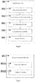
- the working principle of determining the brightness value of the original pathological section image by using the first detection unit B1 specifically comprises:
- the second detection unit B2 specifically comprises:
- the original pathological section image is formed by jointing at least two digital pathological section images.
- An original pathological section image jointed by one digital pathological image 11 and another digital pathological section image 12 is shown in Figure 4 as an example for the illustration of the technical schemes of the present invention.
- a digital pathological section image 11 and a digital pathological section image 12 are jointed to each other, and therefore, it can be seen that the same cellular tissue may be displayed on the jointing region 13 in the digital pathological section image 11 and the digital pathological section image 12.
- the focus of the present invention is on how to determine whether the definition at the jointing region of these two digital pathological images is qualified or not. Further, at least one jointing region 13 exists in an original pathological section image, while in this embodiment, only one jointing region 13 is taken as an example for illustration.
- the second detection module B21 obtains the gradient value of the digital pathological image 11 to function as the first gradient value, and obtains the gradient value of the digital pathological image 12 to function as the second gradient value.
- the second standard unit B22 provides a preset gradient ratio, which may be preset according to the overall definition of the original pathological section image or may be set by the user according to the actual situation.
- the second comparison module B23 compares the ratio of the first gradient value to the second gradient value with the preset gradient ratio:
- the above definition judgment method can objectively judge the quality of an image, which not only avoids the defect of inconsistent evaluation result due to people's subjective factors, but also reduces the workload of the operator involved in evaluating the image quality.
- the second comparison module B23 compares the ratio of the first gradient value to the second gradient value with the preset gradient ratio, and according to the comparison result, when the ratio of the first gradient value to the second gradient value is less than the preset gradient ratio, it is determined that the definition of the spliced section where the two digital pathological images are spliced to each other is unqualified; when the ratio of the first gradient value to the second gradient value is greater than or equal to the preset gradient ratio, it is determined that the definition of the jointing region where the two digital pathological images are spliced to each other is qualified.
- the second comparison module compares the ratio of the first gradient value to the second gradient value with the preset gradient ratio, and according to the comparison result, when the ratio of the first gradient value to the second gradient value is greater than or equal to the preset gradient ratio, it is determined that the definition of the jointing region where the two digital pathological images are jointed to each other is unqualified; when the ratio of the first gradient value to the second gradient value is less than the preset gradient ratio, it is determined that the definition of the jointing region where the two digital pathological images are jointed to each other is qualified.
- the second detection unit B2further comprises: an identification module B24, connected to the second comparison module B23, for identifying the jointing region on the digital pathological image where the second comparison module determines the definition of the digital pathological image is unqualified.
- unqualified jointing region 13 after unqualified jointing region 13 is determined, it can be marked at the unqualified jointing region 13 in a different manner, for example, a circular dotted box, or a square box, or a colored mark and so on.
- An additional detection system may also be used to set a serial number for each jointing region. When a jointing region 13 is detected as unqualified, the serial number corresponding to the jointing region 13 is displayed in the detection system. In this embodiment, a circular dotted box is used to identify the jointing region 13 with unqualified definition, as shown in Figure 4 .
- the identification module B24 identifies the jointing region 13 of the digital pathological section image in which the definition is unqualified, whether to use the digital pathological section or not depends on how bad the digital pathological image is. For example, when the number of unqualified jointing region 13 indicated in the digital pathological section exceeds a preset number (which may be three or five or set by the user according to the actual situation), it is determined that the whole original pathological image is unqualified, and rescanning and redetection of the digital pathological section is needed. Conversely, as long as the number of unqualified jointing region 13 does not exceed the preset number, it is still considered that the original pathological section image can be used, that is, the original pathological section image is deemed to be qualified as a whole.
- a preset number which may be three or five or set by the user according to the actual situation
- the second detection unit B2further comprises: a storage module B25, connected to the second comparison module B23, for temporarily storing the digital pathological image whose definition is determined to be qualified by the second comparison module.
- the working principle of the second detection unit B2 for detecting the definition of jointing region of the original pathological section image formed by jointing a plurality of digital pathological images specifically comprises:
- the image processing end B further comprises: an adjusting unit B4, connected to the output unit B3, for adjusting, before the digital pathological section image is sent out by the output unit, the second section image according to the relative position between the first section image and
- the adjusting unit B4 is provided to achieve the purpose of automatic rotation matching of the digital pathological sections.
- the adjusting unit B4 can be formed by using the third processor in the image processing end B, that is, achieving the function of the adjusting unit B4 by using a third processor.
- the third processor may also be integrated with the first processor and the second processor in a processing chip. Accordingly, the above three processors can also be set alone and work independently.
- adjusting unit B4 specifically comprises:
- the outline of the first section image is enlarged by using the background processing module B41, and is filled with a blank background in the enlarged portion.
- the initial first section image T1 is shown in Figure 6
- the enlarged first section image T1' is shown in Figure 7 , it can be seem from Figures 6 and 7 that it does not enlarge the whole first section image T1, but only enlarges the outline.
- the body portion thereof (the portion of the initial first section image T1) has not been enlarged, and thus in the first section image T1', the section tissue of the first section has not been distorted by stretching, and the enlarged portion is filled with blank background, to form the enlarged first section image T1' as shown in Figure 7 .
- the first rotating module B42 is used to align the endpoint of the second section image, coinciding with the original point of the second XOY coordinate axis, with a preset rotating point in the enlarged first section image.
- the endpoint of the second section image coinciding with the original point of the second XOY coordinate axis is the endpoint of coordinates (0, 0) in the second XOY coordinate axis, which aligns with the preset rotating point in the enlarged first section image.
- the first grayscale processing module B43 is used to obtain a gray value of a preset first determination point on the enlarged first section image and to obtain a gray value of the second determination point on the second section image corresponding to the first determination point.
- the second determination point corresponds to the first determination point means that when the endpoint of the second section image aligns with the preset rotating point of the first section image, the second section image is overlapped with the first section image, and the second determination point is a point coinciding with the first determination point.
- the position of the second determination point coincides with that of the first determination point.
- the gray value at the first determination point and the gray value at the second determination point are obtained respectively by calculating, and the grayscale comparison value under the current position is obtained by calculation.
- the second rotating module B44 is used to rotate the second section image clockwise about the endpoint coinciding with the original point of the second XOY coordinate axis by a preset angle.
- the determination module B45 is used to determine whether the second section image has rotated about 360 degrees. If not, keep rotating the second section image by using the second rotating module B44 and judge the second section image by using the determination module B45, till the second section image has rotated over 360 degrees.
- the preset angle in Step S4 may be 1 degree, that is, the second section image is judged when it is rotated by 1 degree each time until it is rotated about 360 degrees in the clockwise direction.
- the corresponding grayscale comparison value is obtained after rotating every preset angle (e.g., rotate about 1 degree each time), and a adjusting module B46 is used to extract the smallest grayscale comparison value among all of the grayscale comparison values, and adjusting the second section image according to the relative position between the first section image and the second section image corresponding to the obtained grayscale value.
- the initial position refers to a position where the endpoint of the second section image does not coincide with the preset rotating point of the first section image, that is, a position where the second section image is placed in the same direction as the first section image (refers to Figures 6 and 8 ).
- the adjustment scheme is as follows: rotating the second section image clockwise about 180 degrees based on the initial position of the second section image.
- the size of the first section image and the size of the second section image may not be the same, wherein W 1 represents the width of the first section image, and H 1 represents the height of the first section image; accordingly, W 2 represents the width of the second section image, and H 2 represents the height of the second section image, and the above settings are available hereinafter.
- the above mentioned background processing module B41 is used to enlarge the first section image to a rectangle graph with a width A and a height A, the value of A is obtained according to the above mentioned formula (1), and the enlarged portion is filled with a blank background.
- the first section image T1 before enlargement is as shown in Figure 6
- the enlarged first section image T1' is as shown in Figure 7 .
- the value range of the coordinate (m, n) of the preset rotating point satisfies the follows: 0 ⁇ m ⁇ W 1 ⁇ W 2 ; 0 ⁇ n ⁇ H 1 ⁇ H 2 ; wherein,
- the first grayscale processing module B43 further comprises:
- the first determination point can be represented as P 1 (i+m, j+n), and the second determination point can be represented as P 2 (i, j). Then: 0 ⁇ i ⁇ W 2 ; 0 ⁇ j ⁇ H 2 ;
- the second judgment point has a value in the range of (0, 0) to (W 1 , H 1 ).
- the gray value of each of the selected first determination points and the corresponding second determination points is obtained respectively.
- the gray value of the first determination point is regarded as a first grayscale value
- the gray value of the second determination point is regarded as a second grayscale value.
- a grayscale comparison value of the selected first determination point and the second determination point is obtained according to the first gray value and the second grayscale value.
- each time the second section image rotates by a preset angle the grayscale comparison value in the state of the rotation angle is obtained.
- a grayscale comparison value S (30°) is obtained by calculation
- the grayscale comparison value S 60° is obtained by calculation, and so on. That is, in the grayscale acquisition component B434, after the grayscale comparison value with the smallest value is obtained, and the obtained grayscale comparison value is regarded as the grayscale comparison value under the relative position between the first section image and the second section image, the rotation angle of the second section image under the current relative position relative to the initial position is recoded.
- the image processing end B further comprises:
- the preview of the section needs to be processed in advance, the tissue is accurately identified, and the related information (that is, the region where the section tissue exists) is extracted, so as to make the scanning more accurate and effectively reduce the blank part included in the final digital pathological section image, and to increase the physician's efficiency in the identification of the section image.
- the scanning end before the scanning end scans the section tissue, it roughly scans the section tissue and forms a preview thereof, and sends the preview to the image processing end B.
- an identification unit B5 is provided in the image processing end B, and the identification unit B5 is configured to identify the area where the section tissue exists in the image according to the preview transmitted from the scanning end A, and the identification unit B5 keeps the area where the section tissue is located and deletes other areas, so as to form a section tissue image and send the section tissue image back to the scanning end A.
- the scanning end A finally performs a formal scanning of the pathological section according to the section tissue image, that is, only the part of the section tissue corresponding to the section tissue image is scanned to form a corresponding original pathological section image and the corresponding original pathological section image is transmitted to the image processing end B for further processing.
- the identification unit B5 may be a fourth processor disposed in the image processing end B, that is, the fourth processor may be used to achieve the function of the identification unit B5.
- the fourth processor may be integrated with the first processor, the second processor, and the third processor in the same processing chip, or may be set alone and work independently, and which will not be repeated herein.
- the identification unit B5 specifically comprises:
- the image processing technology is commonly used to carry out gray-scale processing on the preview, and to discriminate the tissue, the background, the impurities of the section or stains from section according to the brightness difference, so as to identify and extract the tissue part.
- This method is generally for identification of one or several specific types of section tissues, not applicable to most of the sections. And the case that the tissue is omitted, and that the impurities and the stains are mistakenly identified as the tissue is often exist during the traditional way of brightness recognition, which makes it almost impossible to achieve an accurate identification, thus reducing the accuracy and the efficiency of identifying the section tissue.
- the tissue part is effectively identified as possible by discriminating the tissue and impurities in characteristics such as color and geometric shape. At the same time, a majority of the impurities and the stains are identified and eliminated, thereby separating the tissue part in the section preview in a more accurate way.
- the working principle of the identification unit B5 is as follows:
- the second elimination module B54 may judge the section tissue according to one or more rules described below:
- the impurity can be differentiated from the tissue based on their respective brightness value.
- Embodiments of four rules have been listed above upon which the second elimination module B54 can determine the section tissue, in the present invention, one or more embodiments can be applied to the second elimination module B54.
- a domain that meets at least two of the above four rules may be determined as a connected domain in which a section tissue exits, and finally a section tissue image is generated.
- the four above rules can be applied at the same time, that is, the domain that meets the above four rules is selected as the connected domain in which the section tissue exists, and thus, the section tissue image is generated and output.
- the first elimination module B53 may apply at least one of the elimination rules listed below to eliminate stains in the section information graph, specifically comprising:
- stains in the section information graph can be eliminated respectively according to the area, the length and width, and the area proportionality coefficient of the connected domain. It should be noted that the determination of the above three rules will not be affected by the order of execution, the three rules can be executed simultaneously, and stains in the section information graph can be eliminated in any order that can be executed. Moreover, those skilled in the art can predict the effect of the above three rule determination on eliminating the stains in the section information graph without consideration of the order of execution in the first elimination module B53.
- the reason why adopts the judgment rule of eliminating the connected domain having an area less than a preset area is that the area of dust in the impurity and the spot-like stain on the section is at a few hundred pixel level, much less than the area of the tissue, thus, a connected domain with an area less than a preset area can be eliminated, and the preset area can be set to be similar to the area of general impurity, for example, 1200 pixels.
- the step of eliminating the connected domain having a length-to-width ratio less than a preset length-to-width coefficient is a connected domain wherein the connected domain having a special length-width ratio is deleted. Due to staining of section or other operational reasons, stains on the edges of cover slip tend to be in the form of horizontal strips or vertical strips and have a length and width, with very large size or very small size. Therefore, the connected domain with the special length-width ratio can be eliminated.
- the judgment rule of eliminating the connected domain having an area proportion coefficient less than a preset area proportion coefficient divide the area of the connected domain by the product of the length and width of the area to obtain the area proportion coefficient.
- the area proportion coefficient is less than a preset area proportion coefficient, for example 1/9, it indicates the contour of the connected domain is large, but that a little section information exists, because it is a domain composed by the connection of a plurality of long strip stains on the edges of the cover slip, therefore, the connected domain should be eliminated.
- the first elimination module B53 can be implemented by using a processor having image recognition and comparison function, which will not be repeated herein.
- the image acquisition module B51 comprises:
- the pathological section is placed on a slide, and is covered with a cover slip, on the one hand, to prevent dust from falling onto the tissue, and on the other hand, to fix the tissue.
- the edges of the background image and the preview are the edges of the slide and the cover slip, and tissue information does not exist here. In order to exclude interference as much as possible, these edges need to be cut.
- the first elimination module B53 before the stains in the section information graph are eliminated by the first elimination module B53, in order to highlight the difference between the section tissue and most of the impurities, the first elimination module B53 can be used to perform image binaryzation processing on the section information graph, followed by the elimination of stains. More specific embodiments of achieving image binaryzation processing are known in the prior art, which will not be repeated herein.
- a threshold value on which the image binaryzation processing is based can be set to be slightly lower, so as to meet the identification requirements.
- the first elimination module B53 can be used to perform an opening operation on the section information graph to separate the edge between the smaller connected domain and the larger connected domain to smooth the contour of the section information graph.
- Figures 12-20 show the whole process of identifying the preview of the pathological section by using the identification unit B5 and finally obtaining the section tissue image in the technical scheme of the present invention.
- Figure 12 shows a background image of a blank section
- Figure 13 is a preview with tissues which is photographed. Since instruments are likely to be photographed within the edges of the background image and the preview, the edges of Figure 12 and/or Figure 13 may be cut off such that interference from the edges of the preview and/or the background image may be eliminated.
- Figure 14 shows an embodiment of cutting off the edge in Figure 13 . Then, the gray value of the preview having been cut off the edge is subtracted from the gray value of the background image having been cut off the edge to obtain a section information graph as shown in Figure 15 .
- the image binaryzation processing is performed to further distinguish the tissue from the impurity, and Figure 16 is obtained.
- Figure 16 is obtained.
- the tissue section image shown in Figure 18 can be obtained by performing the rule of geometric shape judgment (the first rule applied by the second elimination module B54);
- the tissue section image shown in Figure 19 can also be obtained by the color judgment rule (the second rule applied by the second elimination module B54); and based on Figures 18 and 19 , it is determined whether the connected domain is regarded as the tissue or not, and the identified result is shown in Figure 20 .
- the second elimination module B54 applies two judgment rules of the connected domain at the same time, and only the connected domain that satisfies both of the two judgment rules can be regarded as the connected domain in which the section tissue exits.
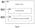
- the output unit B3 specifically comprises:
- the current digital pathological section image is basically not encrypted or any common data encryption operations are barely performed in the transmission process. Therefore, the current digital pathological section image in the transmission process is prone to cause the leak of information, thus, patient's information security cannot be guaranteed. And the data confidentiality is relatively poor. In this embodiment, many improvements have been done in terms of encrypted transmission for the above problems.
- each of the digital pathological section images is respectively divided into a plurality of local images, and each of the local images corresponds to an unique piece of coordinate information, and the plurality of local images form a global graph corresponding to the digital pathological section images.
- the digital pathological section image After the digital pathological section image is encrypted, it is uploaded to the remote server C and managed by the remote server C.
- the physician the second client end E
- the digital pathological section image need to be decrypted. If the digital pathological section image is leaked to the extranet, other client ends cannot access the encrypted information corresponding to the related digital pathological section image except for the remote server C responsible for managing the digital pathological section image. Therefore, the digital pathological section image will not be opened, and patient's information security can be ensured.
- the global graph of the digital pathological section image is divided into a plurality of local images, and the coordinate information of each local image is respectively encrypted to complete the encryption operation for the digital pathological section image, so as to avoid lowering the speed of browsing the encrypted digital pathological section image due to the excessively large size of the digital pathological section image.
- the physician decrypts the digital pathological section image by using the second client end E, the plurality of local images are respectively decrypted to ensure the browsing speed and improve the user experience.
- the output unit B3 apart from the function of achieving the transmission of the digital pathological section image, the output unit B3 further comprises the function of dividing the digital pathological section image and respectively encrypting the local images.
- the output unit B3 may be a processing chip including data communication function, that is, a communication chip and a processor achieving data encryption function are integrated in a processing chip to achieve the functions of the output unit B3.
- the principle of encrypting and transmitting the digital pathological section image by output unit B3 specifically comprises:
- the digital pathological section scanning system comprises a plurality of scanning ends A, each of the scanning ends A corresponding to one of the image processing ends B ( Figure 1 only shows one scanning end A); each of the image processing ends has an unique authorization code, and each of the scanning ends has an unique machine code, and the authorization code and the machine code forms a key; and the key is provided to the output unit of the image processing end for performing an encryption operation on the digital pathological section image, and the image processing end provides the key to the remote server while sending the digital pathological section image to the remote server.
- the digital pathological section scanning system may comprise a plurality of scanner devices (the scanning end A), each of the scanner devices is connected to a specific image processing server (the image processing end B).
- the original pathological section image obtained by scanning via a specific scanning end A is processed via its specific image processing end B to obtain a digital pathological section image, and the obtained digital pathological section image is uploaded to the remote server C. Therefore, it can be considered that a scanning end A, together with its corresponding image processing end B in the digital pathological section scanning system, forms a workstation for obtaining the digital pathological section image by scanning.
- each of the scanning ends A has an unique machine code
- each of the image processing ends B also has an unique authorization code.
- the original pathological section image obtained by scanning via a specific scanning end A is processed via its specific image processing end B to obtain a digital pathological section image
- the key corresponding to the digital pathological section image is the key formed of the machine code of the scanning end A and the authorization code of the image processing end B.
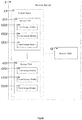
- each of the storage units C11 in the remote server C specifically comprises:
- the local images of the digital pathological section image only accessible to the attending physician associated with the storage unit C11 is stored in each of the storage units C11, however, in addition to the above local images, the encrypted information of each of the local images and the key of the digital pathological section image should also be stored in each of the storage units C11.
- the remoter server C provides an access unit C2 capable of sending the local images, the encrypted information and the key in the storage unit C11 to the second client end E for decryption.
- the remote server C may also exhibit the function of online encryption, that is, the local images, performing encryption and jointing operation at the remote server C directly through the encrypted information and the key saved in the corresponding storage unit C11, then a complete digital pathological section image is provided to the attending physician.
- remote server C specifically comprises:
- the present invention manages to associate the digital pathological section image obtained outside of a hospital with the selected attending physician by means of the first client end D and the scanning end A, and the medical record information of the patient is sent to the remote server C for designating the specific attending physician to browse and diagnose the digital pathological section image of the patient.
- the remote server C allocates a storage unit C11 to each attending physician. After the medical record information and the corresponding digital pathological section image sent by the first client end D is analyzed by the data analysis unit C4 in the remote server C to obtain the attending physician information thereof, the medical record information and the corresponding digital pathological section image are stored in the storage unit C11 of corresponding attending physician, and thus making it easier for the attending physician at the second client end E to check how many digital pathological section images there are in the storage unit C11 when logging in the remote server C, facilitating the attending physician to make a diagnosis timely.
- the attending physician logs into the remote server C by entering account information and a password in the second client end E, and the remote server C identifies the account information and the password, if the account information and the password matches with the attending physician, the second client end E is authorized to access the corresponding storage unit C11 in the storage space C.
- the remote server C may send the access path of the corresponding storage unit C11 to the second client end E, the second client end E then can browse and diagnose the digital pathological section image saved in the corresponding storage unit C11 according to the access path.
- the diagnosis made by the attending physician at the second client end E is processed by the medical record processing unit C7 in the remote server C to form a diagnostic report, and the diagnostic report is saved in the remote server C, wherein the remote server E may further send the diagnostic report to the corresponding first client end D, such that the patient involved may get to know the diagnostic result.
- the second client end E may access the medical record information and the corresponding digital pathological section image concerning the related patient in the remote server C by means of data access interface provided by the remote server C, and thus the attending physician at the second client end E may make a diagnosis in time.
- remote server further comprises:
- the diagnosis prompt unit C9 will generate the diagnosis prompt message corresponding to the patient's medical record information, wherein the diagnosis prompt message indicates that the attending physician has made the diagnosis.
- the diagnosis prompt message is pushed to the corresponding first client end D by the pushing unit C10, and the first client end D may obtain the diagnostic report of related patient according to the diagnosis prompt message.
- the digital pathological section scanning system further comprises a short message notification server F, wherein the short message notification server F provides an interface for connecting to the remote server C, and the short message notification server F further remotely connects to the second client end E; as shown in Figure 23 , the remote server C further comprises:
- the remote server E in order to remind the attending physician to make contact with the patient for diagnosis, the remote server E generates the consultation prompt information through the notification unit C12, and the consultation prompt information is sent to second client end E of the corresponding attending physician by the short message notification server F via invoking the interface, then it is convenient for the attending physician to view the digital pathological section image and make a diagnosis in time.
- scanning end A further comprises:
- the scanning end comprises a section platform A1 than can move on a horizontal XY plane, and the movement of the section platform A1 is controlled by a drive motor.
- An illumination scanning device A3 is disposed above the section platform A1 for providing light source required by the scanning end A, and for scanning the pathological section fixed on the slide on the section platform A1.
- the automatic loading device A2 comprises a section box A21 and a loader A22.
- a plurality of slides fixed with pathological sections are installed in the section box in advance, and each slide has a respective number. It is preferable that a section box A21 may disposably accommodate 40 slides, and the specific structure of the section box A21 is as shown in Figures 25-26 .
- the driving circuit board in the automatic loading device A2 will load the slide with corresponding number in the section box A21 onto the section platform A1 located above the automatic loading device A2.
- the automatic loading device A2 will rise to the position as high as the section platform A1, then the slide with corresponding number is pushed out of the section box A21 to the position A11 of the section box through the loader A22 (which is a pushing tongue shown in Figures 27 and 28 ) to be scanned by the scanning end A.
- the illumination scanning device A3 further comprises:
- the portion shown in Figure 29 is actually arranged on the back of the portion shown in Figure 24 .
- the LED light source A31 is arranged at one side of the scanning unit A32 and provides the light source necessary for scanning to the scanning unit A32.
- the scanning unit A32 may be a conventional scanning lens, comprising multiple objective lenses and a line camera having a scanning path similar to that of the scanning lens, which will not be repeated herein.
- the bright-to-fluorescence switching device A33 may make it possible for the scanning unit A32 to operate both at the bright field scanning mode and at the fluorescence scanning mode.
- the bright field scanning mode means scanning the pathological section by using the bright field transmission light; and the fluorescence scanning mode means scanning the pathological section by using fluorescence reflected light.
- Figure 30 shows a state in which the scanning unit A32 operates in the bright field scanning mode
- Figure 31 shows a state in which the scanning unit A32 operates in the fluorescence scanning mode by shielding the lens via the bright-to-fluorescence switching device A33.
Landscapes
- Engineering & Computer Science (AREA)
- Health & Medical Sciences (AREA)
- General Health & Medical Sciences (AREA)
- Physics & Mathematics (AREA)
- General Physics & Mathematics (AREA)
- Medical Informatics (AREA)
- Signal Processing (AREA)
- Nuclear Medicine, Radiotherapy & Molecular Imaging (AREA)
- Life Sciences & Earth Sciences (AREA)
- Theoretical Computer Science (AREA)
- Public Health (AREA)
- Multimedia (AREA)
- Biomedical Technology (AREA)
- Primary Health Care (AREA)
- Epidemiology (AREA)
- Radiology & Medical Imaging (AREA)
- Computer Security & Cryptography (AREA)
- Computer Networks & Wireless Communication (AREA)
- Pathology (AREA)
- Molecular Biology (AREA)
- Immunology (AREA)
- Biochemistry (AREA)
- Analytical Chemistry (AREA)
- Chemical & Material Sciences (AREA)
- Quality & Reliability (AREA)
- Computer Vision & Pattern Recognition (AREA)
- Computing Systems (AREA)
- General Engineering & Computer Science (AREA)
- Veterinary Medicine (AREA)
- Animal Behavior & Ethology (AREA)
- Surgery (AREA)
- Heart & Thoracic Surgery (AREA)
- Biophysics (AREA)
- Measuring And Recording Apparatus For Diagnosis (AREA)
- Image Analysis (AREA)
- Investigating Or Analysing Biological Materials (AREA)
Claims (26)
- Digitales Abtastsystem für pathologische Schnitte, umfassend: ein Abstastende, ein Bildverarbeitungsende, einen Remote-Server, ein erstes Client-Ende und ein zweites Client-Ende, wobei das Abtastende mit dem Bildverarbeitungsende verbunden ist und der Remote-Server mit dem Bildverarbeitungsende, dem ersten Client-Ende und dem zweiten Client-Ende verbunden ist;
wobei das Abtastende dazu ausgelegt ist, um einen abzutastenden pathologischen Schnitt abzutasten, um ein ursprüngliches pathologisches Schnittbild zu bilden, und um das ursprüngliche pathologische Schnittbild zur Verarbeitung an das Bildverarbeitungsende zu übertragen, wobei das ursprüngliche pathologische Schnittbild durch Zusammenfügen einer Vielzahl digitaler Bilder an einer Fügestelle gebildet wird;
wobei das Bildverarbeitungsende dazu ausgelegt ist, das ursprüngliche pathologische Schnittbild, das durch das Abtastende übertragen wird, zu verarbeiten, um ein entsprechendes digitales pathologisches Schnittbild zu bilden und das entsprechende digitale pathologische Schnittbild zu speichern, und um das digitale pathologische Schnittbild an den Remote-Server zu senden;
wobei das Bildverarbeitungsende ferner umfasst:eine erste Erkennungseinheit zum Erkennen eines Helligkeitswertes des ursprünglichen pathologischen Schnittbildes und zum Ausgeben eines ersten Erkennungsergebnisses, das angibt, ob der Helligkeitswert des ursprünglichen pathologischen Schnittbildes geeignet ist;eine zweite Erkennungseinheit zum Erkennen der Definition an der Fügestelle des ursprünglichen pathologischen Schnittbildes und zum Ausgeben eines zweiten Erkennungsergebnisses, das angibt, ob die Definition an der Fügestelle geeignet ist;eine Ausgabeeinheit, die mit der ersten Erkennungseinheit bzw. mit der zweiten Erkennungseinheit verbunden ist, die ausgelegt ist, um nach dem ersten Erkennungsergebnis und dem zweiten Erkennungsergebnis das ursprüngliche pathologische Schnittbild mit geeignetem Helligkeitswert und Definition als das digitale pathologische Schnittbild zu nehmen und das digitale pathologische Schnittbild an den Remote-Server zu senden;wobei das erste Client-Ende dazu ausgelegt ist, eine Krankenakte an den Remote-Server zu übertragen und die Krankenakte Informationen eines behandelnden Arztes umfasst, die ein Konto des behandelnden Arztes darstellen, der durch das erste Client-Ende ausgewählt wird;wobei der Remote-Server einen Speicherplatz umfasst, der eine Speichereinheit aufweist, die den Informationen jedes behandelnden Arztes entspricht;wobei der Remote-Server das erhaltene digitale pathologische Schnittbild mit den Informationen des behandelnden Arztes, die in der Krankenakte enthalten sind, verknüpft und das digitale pathologische Schnittbild in der Speichereinheit speichert, die den Informationen des behandelnden Arztes entspricht;wobei der Remote-Server gleichzeitig dem zweiten Client-Ende, das die Anmeldung auf dem Konto des behandelnden Arztes überprüft hat, ermöglicht, auf den digitalen pathologischen Schnitt zuzugreifen, der in der Speichereinheit gespeichert ist, die dem Konto des behandelnden Arztes entspricht. - Digitales Abtastsystem für pathologische Schnitte nach Anspruch 1, wobei die erste Erkennungseinheit insbesondere umfasst:ein erstes Erkennungsmodul zum Erkennen eines Helligkeitswertes des ursprünglichen pathologischen Schnittbildes;ein erstes Standardmodul, das einen voreingestellten Helligkeitsbereich eines Standardbildes bereitstellt, das dem ursprünglichen pathologischen Schnittbild entspricht;ein erstes Vergleichsmodul, das mit dem ersten Erkennungsmodul bzw. mit dem ersten Standardmodul verbunden ist, um den Helligkeitswert des ursprünglichen pathologischen Schnittbildes mit dem Helligkeitsbereich des Standardbildes zu vergleichen;wobei das erste Vergleichsmodul dazu ausgelegt ist, um das erste Erkennungsergebnis auszugeben, das angibt, dass der Helligkeitswert des ursprünglichen pathologischen Schnittbildes geeignet ist, wenn der Helligkeitswert des ursprünglichen pathologischen Schnittbildes innerhalb des Helligkeitsbereichs des Standardbildes ist, und um das erste Erkennungsergebnis auszugeben, das angibt, dass der Helligkeitswert des ursprünglichen pathologischen Schnittbildes nicht geeignet ist, wenn der Helligkeitswert des ursprünglichen pathologischen Schnittbildes außerhalb des Helligkeitsbereichs des Standardbildes fällt.
- Digitales Abtastsystem für pathologische Schnitte nach Anspruch 2, wobei die erste Erkennungseinheit ferner umfasst:
ein Bildkompensationsmodul, das mit dem ersten Vergleichsmodul verbunden ist, wobei, wenn das erste Vergleichsmodul das erste Erkennungsergebnis ausgibt, das angibt, dass der Helligkeitswert des ursprünglichen pathologischen Schnittbildes nicht geeignet ist, das Bildkompensationsmodul eine Beleuchtungskompensationsanweisung basierend auf einer Differenz zwischen dem Helligkeitswert des nicht geeigneten ursprünglichen pathologischen Schnittbildes und dem Helligkeitsbereich des Standardbildes ausgibt, dann das Bildverarbeitungsende die Beleuchtungskompensationsanweisung an das Abtastende zurückführt, um das ursprüngliche pathologische Schnittbild zu erhalten, indem das Abtastende zum erneuten Abtasten gesteuert wird. - Digitales Abtastsystem für pathologische Schnitte nach Anspruch 1, wobei die zweite Erkennungseinheit insbesondere umfasst:ein zweites Erkennungsmodul, das ausgelegt ist, um zwei digitale pathologische Bilder zu verarbeiten, die zusammengefügt sind, um einen Bildgradienten eines digitalen pathologischen Bildes zu erhalten, um als ein erster Gradientenwert zu dienen, und um einen Bildgradienten des anderen digitalen pathologischen Bildes zu erhalten, um als ein zweiter Gradientenwert zu dienen;ein zweites Standardmodul, das ausgelegt ist, um ein voreingestelltes Gradientenverhältnis vorab bereitzustellen;ein zweites Vergleichsmodul, das mit dem zweiten Erkennungsmodul bzw. dem zweiten Standardmodul verbunden ist, das ausgelegt ist, um das Verhältnis des ersten Gradientenwertes und des zweiten Gradientenwertes mit dem voreingestellten Gradientenverhältnis zu vergleichen und, wenn das Verhältnis nicht mit dem voreingestellten Gradientenverhältnis übereinstimmt, zu bestimmen, dass die Definition der Fügestelle, wo die zwei digitalen pathologischen Bilder zusammengefügt sind, nicht geeignet ist und daher das zweite Erkennungsergebnis auszugeben, das angibt, dass die Definition der Fügestelle, wo die ursprünglichen pathologischen Bilder zusammengefügt sind, nicht geeignet ist.
- Digitales Abtastsystem für pathologische Schnitte nach Anspruch 4, wobei, wenn der erste Gradientenwert kleiner oder gleich dem zweiten Gradientenwert ist, das voreingestellte Gradientenverhältnis kleiner oder gleich 1 ist;
dann das zweite Vergleichsmodul das Verhältnis des ersten Gradientenwertes und des zweiten Gradientenwertes mit dem voreingestellten Gradientenverhältnis vergleicht und gemäß dem Vergleichsergebnis,
wenn das Verhältnis von erstem Gradientenwert und zweitem Gradientenwert kleiner als das voreingestellte Gradientenverhältnis ist, bestimmt wird, dass die Definition der Fügestelle, wo die zwei digitalen pathologischen Bilder zusammengefügt sind, nicht geeignet ist;
wenn das Verhältnis des ersten Gradientenwertes und des zweiten Gradientenwertes größer oder gleich dem voreingestellten Gradientenverhältnis ist, bestimmt wird, dass die Definition der Fügestelle wo die zwei digitalen pathologischen Bilder zusammengefügt sind, geeignet ist. - Digitales Abtastsystem für pathologische Schnitte nach Anspruch 4, wobei, wenn der erste Gradientenwert größer oder gleich dem zweiten Gradientenwert ist, das voreingestellte Gradientenverhältnis größer als 1 ist;
dann das zweite Vergleichsmodul das Verhältnis des ersten Gradientenwertes und des zweiten Gradientenwertes mit dem voreingestellten Gradientenverhältnis vergleicht und gemäß dem Vergleichsergebnis,
wenn das Verhältnis von erstem Gradientenwert und zweitem Gradientenwert größer oder gleich dem voreingestellten Gradientenverhältnis ist, bestimmt wird, dass die Definition der Fügestelle, wo die zwei digitalen pathologischen Bilder zusammengefügt sind, nicht geeignet ist;
wenn das Verhältnis des ersten Gradientenwertes und des zweiten Gradientenwertes kleiner als das voreingestellte Gradientenverhältnis ist, bestimmt wird, dass die Definition der Fügestelle wo die zwei digitalen pathologischen Bilder zusammengefügt sind, geeignet ist. - Digitales Abtastsystem für pathologische Schnitte nach Anspruch 4, wobei die zweite Erkennungseinheit ferner umfasst:
ein Identifikationsmodul, das mit dem zweiten Vergleichsmodul verbunden ist, um die Fügestelle auf dem digitalen pathologischen Bild zu identifizieren, wenn das zweite Vergleichsmodul bestimmt, dass die Definition des digitalen pathologischen Bildes nicht geeignet ist. - Digitales Abtastsystem für pathologische Schnitte nach Anspruch 1, wobei in dem digitalen Abtastsystem für pathologische Schnitte das Schnittschneiden am menschlichen Gewebe derselben Person durchgeführt wird und zwei unterschiedliche ursprüngliche pathologische Schnittbilder durch Abtasten über das Abtastende gebildet werden;
wobei im Bildverarbeitungsende das Abtastsystem jeweils den Helligkeitswert und die Definition der Fügestelle der zwei ursprünglichen pathologischen Schnittbilder erkennt und zwei digitale pathologische Schnittbilder bildet, die jeweils den zwei ursprünglichen pathologischen Schnittbildern entsprechen, die als ein erstes Schnittbild und ein zweites Schnittbild dienen;
wobei sich das erste Schnittbild in einer ersten XOY-Koordinatenachse befindet, der einen Endpunkt des ersten Schnittbildes als ursprünglichen Punkt fungiert, und
sich das zweite Schnittbild in einer zweiten XOY-Koordinatenachse befindet, die einen Endpunkt des zweiten Schnittbildes als einen ursprünglichen Punkt fungiert;
wobei das Bildverarbeitungsende ferner umfasst:
eine Einstelleinheit, die mit der Ausgabeeinheit verbunden ist, um vor dem Senden des digitalen pathologischen Schnittbildes durch die Ausgabeeinheit das zweite Schnittbild gemäß der relativen Position zwischen dem ersten Schnittbild und dem zweiten Schnittbild einzustellen und das zweite Schnittbild und das erste Schnittbild in ein entsprechendes digitales pathologisches Schnittbild zu integrieren, das durch die Ausgabeeinheit an den Remote-Server zu senden ist. - Digitales Abtastsystem für pathologische Schnitte nach Anspruch 8, wobei die Einstelleinheit insbesondere umfasst:ein Hintergrundverarbeitungsmodul zum Ausdehnen der Konturgröße des ersten Schnittbildes und Füllen des vergrößerten Abschnitts des ersten Schnittbildes mit einem leeren Hintergrund;ein erstes Drehmodul, das mit dem Hintergrundverarbeitungsmodul verbunden ist, um den Endpunkt in dem zweiten Schnittbild, der mit dem ursprünglichen Punkt der zweiten XOY-Koordinatenachse zusammenfällt, mit einem voreingestellten Drehpunkt in dem ersten Schnittbild auszurichten;ein erstes Graustufen-Verarbeitungsmodul, das mit dem ersten Drehmodul verbunden ist, um das erste Schnittbild zu verarbeiten, um einen Grauwert eines voreingestellten ersten Bestimmungspunktes zu erhalten und das zweite Schnittbild zu verarbeiten, um einen Grauwert eines zweiten Bestimmungspunkts zu erhalten, der dem ersten Bestimmungspunkt entspricht, gefolgt von dem Erhalten eines Grauvergleichswertes unter der derzeitigen relativen Position zwischen dem ersten Schnittbild und dem zweiten Schnittbild;ein zweites Drehmodul, das mit dem ersten Drehmodul verbunden ist, um das zweite Schnittbild im Uhrzeigersinn um den Endpunkt zu drehen, der mit dem ursprünglichen Punkt der zweiten XOY-Koordinatenachse durch einen voreingestellten Winkel zusammenfällt;ein Bestimmungsmodul, das mit dem ersten Graustufen-Verarbeitungsmodul bzw. dem zweiten Drehmodul verbunden ist, um, nachdem das zweite Drehmodul zu dem zweiten Schnittbild dreht, zu bestimmen, ob das zweite Schnittbild um 360 Grad relativ zu einer anfänglichen Position gedreht hat, und um ein Bestimmungsergebnis auszugeben;wobei das erste Graustufen-Verarbeitungsmodul ferner konfiguriert ist, um gemäß dem Bestimmungsergebnis die Graustufenverarbeitung erneut durchzuführen, wenn sich das zweite Schnittbild nicht um 360 Grad relativ zur Anfangsposition gedreht hat;und das zweite Drehmodul ferner konfiguriert ist, um gemäß dem Bestimmungsergebnis das zweite Schnittbild weiterzudrehen, wenn sich das zweite Schnittbild nicht um 360 Grad relativ zur Anfangsposition gedreht hat;ein Einstellmodul, das mit dem ersten Graustufen-Verarbeitungsmodul bzw. dem Bestimmungsmodul verbunden ist, um gemäß dem Bestimmungsergebnis den Grauwert mit dem kleinsten Wert zu erhalten, wenn sich das zweite Schnittbild um etwa 360 Grad relativ zur Anfangsposition gedreht hat, und um das zweite Schnittbild gemäß der relativen Position zwischen dem ersten Schnittbild und dem zweiten Schnittbild entsprechend dem erhaltenen Graustufenwert einzustellen.
- Digitales Abtastsystem für pathologische Schnitte nach Anspruch 9, wobei das Hintergrundverarbeitungsmodul das erste Schnittbild auf ein Bild mit einer Breite und einer Höhe A vergrößert und den vergrößerten Abschnitt des ersten Schnittbildes mit einem leeren Hintergrund füllt;
wobei, W1 für die Breite des ersten Schnittbildes steht;H1 für die Höhe des ersten Schnittbildes steht.
 - Digitales Abtastsystem für pathologische Schnitte nach Anspruch 10,
wobei der Wertebereich der Koordinate (m, n) des voreingestellten Drehpunkts Folgendes erfüllt:
 m für die X-Achsenkoordinate des voreingestellten Drehpunkts in der ersten XOY-Koordinatenachse steht;n für die Y-Achsenkoordinate des voreingestellten Drehpunkts in der ersten XOY-Koordinatenachse steht;W1 für die Breite des ersten Schnittbildes steht;H1 für die Höhe des ersten Schnittbildes steht;W2 für die Breite des zweiten Schnittbildes steht;H2 für die Höhe des zweiten Schnittbildes steht.
 - Digitales Abtastsystem für pathologische Schnitte nach Anspruch 9, wobei die voreingestellte Koordinate des ersten Bestimmungspunkts einen voreingestellten Wertebereich aufweist;
dann das erste Graustufen-Verarbeitungsmodul ferner umfasst:eine erste Graustufen-Verarbeitungskomponente zum Verarbeiten des ersten Schnittbildes zum Erhalten eines Grauwertes jedes des ersten Bestimmungspunkts innerhalb des Wertebereichs zum Dienen als ein erster Graustufenwert;eine zweite Graustufen-Verarbeitungskomponente zum Verarbeiten des zweiten Schnittbildes zum Erhalten eines Grauwertes jedes des zweiten Bestimmungspunkts, der jedem des ersten Bestimmungspunkts innerhalb des Wertebereichs zum Dienen als ein erster Graustufenwert entspricht;eine dritte Graustufen-Verarbeitungskomponente, die mit der ersten Graustufen-Verarbeitungskomponente bzw. der zweiten Graustufen-Verarbeitungskomponente verbunden ist, um gemäß dem ersten Grauwert und dem entsprechenden zweiten Graustufenwert jeweils jeden entsprechenden Graustufen-Vergleichswert zu erhalten; eine Graustufen-Erfassungskomponente, die mit der dritten Graustufen-Verarbeitungskomponente verbunden ist,um den Graustufen-Vergleichswert mit dem kleinsten Wert zu erhalten, der als der Graustufen-Vergleichswert unter der derzeitigen relativen Position zwischen dem ersten Schnittbild und dem zweiten Schnittbild dient. - Digitales Abtastsystem für pathologische Schnitte nach Anspruch 12, wobei die dritte Graustufen-Verarbeitungskomponente den Graustufen-Vergleichswert gemäß der folgenden Formel erhält:
 S(m,n) für den Graustufen-Vergleichswert steht;(m,n) für den Koordinatenwert des voreingestellten Drehpunkts steht, m für die X-Achsenkoordinate des voreingestellten Drehpunkts in der ersten XOY-Koordinatenachse steht, n die Y-Achsenkoordinate des voreingestellten Drehpunkts in der ersten XOY-Koordinatenachse ist;(i, j) für den Koordinatenwert des zweiten Bestimmungspunkts steht, i die X-Achsenkoordinate des zweiten Bestimmungspunkts in der zweiten XOY-Koordinatenachse ist, j die Y-Achsenkoordinate des zweiten Bestimmungspunkts in der zweiten XOY-Koordinatenachse ist;W2 für die Breite des zweiten Schnittbildes steht;H2 für die Höhe des zweiten Schnittbildes steht;P1 für den ersten Graustufenwert steht;P2 für den zweiten Graustufenwert steht.
 - Digitales Abtastsystem für pathologische Schnitte nach Anspruch 12, wobei die Graustufen-Erfassungskomponente den Graustufen-Vergleichswert mit dem kleinsten Wert erhält, der als der Graustufen-Vergleichswert unter der derzeitigen relativen Position zwischen dem ersten Schnittbild und dem zweiten Schnittbild dient, und zum Aufzeichnen des Drehwinkels des zweiten Schnittbildes relativ zur Anfangsposition;
wobei das Einstellmodul das zweite Schnittbild gemäß dem Drehwinkel entsprechend dem erhaltenen Graustufen-Vergleichswert mit dem kleinsten Wert dreht. - Digitales Abtastsystem für pathologische Schnitte nach Anspruch 1, wobei eine Vorschau des pathologischen Schnitts durch Vor-Abtasten erhalten wird, bevor das Abtastende den pathologischen Schnitt abtastet;
wobei das Bildverarbeitungsende ferner umfasst:eine Identifikationseinheit zum Erkennen der Vorschau zum Erhalten eines Schnittgewebebildes in der Vorschau;wobei das Bildverarbeitungsende das Schnittgewebebild zurück an das Abtastende überträgt und das Abtastende den pathologischen Schnitt gemäß dem Schnittgewebebild abtastet. - Digitales Abtastsystem für pathologische Schnitte nach Anspruch 15, wobei ein leeres Schnittbild durch Abtasten über das Abtastende vorab erhalten wird;
wobei die Identifikationseinheit insbesondere umfasst:ein Bilderfassungsmodul, das ein Hintergrundbild des leeren Schnittbildes bzw. der Vorschau erhält;ein zweites Graustufen-Verarbeitungsmodul, das mit dem Bilderfassungsmodul verbunden ist, um den Grauwert des Hintergrundbildes von dem Grauwert der Vorschau zum Erhalten eines Schnittinformationsgraphen zu subtrahieren;ein erstes Entfernungsmodul, das mit dem zweiten Graustufen-Verarbeitungsmodul verbunden ist, um eine Querverarbeitung an den verbundenen Domänen des Schnittinformationsgraphen durchzuführen, und zum Entfernen von Flecken in dem Schnittinformationsgraphen;ein zweites Entfernungsmodul, das mit dem ersten Entfernungsmodul verbunden ist, um jeweils gemäß dem Attribut der verbundenen Domäne zu beurteilen, ob jede verbundene Domäne in dem Schnittinformationsgraphen, der die Flecken entfernt hat, ein Schnittgewebe ist und um die verbundene Domäne zu entfernen, die nicht das Schnittgewebe ist;ein Rückhaltemodul, das mit dem zweiten Entfernungsmodul verbunden ist, um den Schnittinformationsgraphen als das Schnittgewebebild zurückzuhalten, nachdem die verbundene Domäne, die nicht zu dem Schnittgewebe gehört, entfernt ist. - Digitales Abtastsystem für pathologische Schnitte nach Anspruch 16, wobei das Bilderfassungsmodul umfasst:eine Erfassungskomponente zum Erfassen eines Hintergrundbildes des leeren Schnittbildes bzw. der Vorschau;eine Zuschneidekomponente, die mit der Erfassungskomponente verbunden ist, zum Abschneiden von Randabschnitten des Hintergrundbildes bzw. der Vorschau.
- Digitales Abtastsystem für pathologische Schnitte nach Anspruch 1, wobei die Ausgabeeinheit insbesondere umfasst:ein Schneidemodul zum Schneiden des digitalen pathologischen Schnittbildes in eine Vielzahl von lokalen Bildern;ein Koordinatenverschlüsselungsmodul, das mit dem Schneidemodul verbunden ist, um jeweils einen Verschlüsselungsvorgang zu der Koordinateninformation jedes der lokalen Bilder zum Erhalten von verschlüsselten Informationen jedes der lokalen Bilder durchzuführen;wobei die Ausgabeeinheit die lokalen Bilder und die entsprechende verschlüsselte Information an den Remote-Server sendet, um das digitale pathologische Schnittbild an den Remote-Server zu senden;wobei, nachdem das zweite Client-Ende auf den Remote-Server zugreift und die gespeicherten lokalen Bilder und die entsprechenden Verschlüsselungsinformationen erhält, die mit dem digitalen pathologischen Schnittbild verknüpft sind, jede der verschlüsselten Informationen ausgewertet wird, um die entsprechenden Koordinateninformationen zu erhalten, und gemäß den Koordinateninformationen die lokalen Bilder nacheinander zusammengefügt, um ein vollständiges digitales pathologisches Schnittbild zu bilden, und das vollständige digitale pathologische Schnittbild angezeigt wird, so dass ein Benutzer des zweiten Client-Endes das digitale pathologische Schnittbild diagnostiziert.
- Digitales Abtastsystem für pathologische Schnitte nach Anspruch 18, wobei das digitale Abtastsystem für pathologische Schnitte eine Vielzahl von Abtastenden umfasst, wobei jedes der Abtastenden einem der Bildverarbeitungsenden entspricht;
jedes der Bildverarbeitungsenden einen eindeutigen Autorisierungscode aufweist und jedes der Abtastenden einen eindeutigen Maschinencode aufweist, und der Autorisierungscode und der Maschinencode einen Schlüssel bilden;
wobei der Schlüssel dem Ausgabeende des Bildverarbeitungsendes zum Durchführen eines Verschlüsselungsvorgangs auf dem digitalen pathologischen Schnittbild bereitgestellt wird, und das Bildverarbeitungsende den Schlüssel an den Remote-Server bereitstellt, während er das digitale pathologische Schnittbild an den Remote-Server sendet. - Digitales Abtastsystem für pathologische Schnitte nach Anspruch 19, wobei jede der Speichereinheiten in dem Remote-Server insbesondere umfasst:ein erstes Speichermodul zum Speichern der lokalen Bilder in dem digitalen pathologischen Schnittbild;ein zweites Speichermodul zum Speichern verschlüsselter Informationen, die jedem der lokalen Bilder entsprechen;ein drittes Speichermodul zum Speichern des Schlüssels, der dem digitalen pathologischen Schnittbild entspricht;wobei der Remote-Server ferner umfasst:
eine Zugangseinheit, die mit dem Speicherplatz verbunden ist, um nach der Zugangsanforderung des zweiten Client-Endes die lokalen Bilder, die Verschlüsselungsinformationen und den Schlüssel von der Speichereinheit zu erhalten und um die erhaltenen lokalen Bilder, die Verschlüsselungsinformation und den Schlüssel zu dem zweiten Client-Ende zu senden. - Digitales Abtastsystem für pathologische Schnitte nach Anspruch 1, wobei der Remote-Server insbesondere umfasst:eine erste Erfassungseinheit zum Erfassen des digitalen pathologischen Schnittbildes, das durch das Bildverarbeitungsende gesendet wird;eine zweite Erfassungseinheit zum Erfassen der Krankenakte, die durch das erste Client-Ende gesendet wird;eine Datenanalyseeinheit, die mit der zweiten Erfassungseinheit verbunden ist, um die Informationen des behandelnden Arztes durch Analysieren der Krankenakte zu analysieren;eine Verteilungsverarbeitungseinheit, die mit der Datenanalyseeinheit, der ersten Erfassungseinheit, der zweiten Erfassungseinheit bzw. dem Speicherplatz verbunden ist, um gemäß den analysierten Informationen des behandelnden Arztes die entsprechende Krankenakte und das digitale pathologische Schnittbild in der entsprechenden Speichereinheit in dem Speicherplatz zu speichern, und wobei in der Speichereinheit das digitale pathologische Schnittbild und die Krankenakte miteinander verknüpft gespeichert sind;eine Berechtigungsauthentifizierungseinheit, die mit dem Speicherplatz verbunden ist, um die Kontoinformationen und das Passwort des Kontos des behandelnden Arztes zu überprüfen, die von dem zweiten Client-Ende bereitgestellt werden; und Autorisieren der Berechtigung des zweiten Client-Endes für den Zugang zu der Krankenakte und dem digitalen pathologischen Schnittbild in der entsprechenden Speichereinheit nach Bestätigen der Überprüfung; undeine Krankenakten-Verarbeitungseinheit, die mit dem Speicherplatz verbunden ist, um das digitale pathologische Schnittbild durch das zweite Client-Ende durch Remote-Anmeldung zu diagnostizieren, um einen Diagnosebericht zu bilden, der dem digitalen pathologischen Schnittbild entspricht, und der Diagnosebericht in der Speichereinheit in dem Speicherplatz gespeichert wird, der dem digitalen pathologischen Schnittbild entspricht.
- Digitales Abtastsystem für pathologische Schnitte nach Anspruch 21, wobei der Remote-Server ferner umfasst:eine Diagnose-Eingabeaufforderungseinheit, die mit der Krankenakten-Verarbeitungseinheit verbunden ist, um eine Diagnose-Eingabeaufforderungsinformation zu bilden, die der Krankenakte gemäß dem erzeugten Diagnosebericht entspricht; undeine Schiebeeinheit, die mit der Diagnose-Eingabeaufforderungseinheit verbunden ist, um die Diagnose-Eingabeaufforderungsinformation an das erste Client-Ende zu senden, das die Krankenakte ausgibt.
- Digitales Abtastsystem für pathologische Schnitte nach Anspruch 21, ferner umfassend einen Kurznachricht-Benachrichtigungsserver, wobei der Kurznachricht-Benachrichtigungsserver eine Schnittstelle zum Verbinden mit dem Remote-Server bereitstellt und der Kurznachricht-Benachrichtigungsserver ferner das zweite Client-Ende remote verbindet;
wobei der Remote-Server ferner umfasst:eine Benachrichtigungseinheit, die mit der Datenanalyseeinheit verbunden ist, um entsprechende Beratungs-Eingabeaufforderungsanforderungen gemäß den analysierten Informationen des behandelnden Arztes zu erzeugen;wobei das Abrufen der Schnittstelle über den Remote-Server zum Steuern des Kurznachricht-Benachrichtigungsserver zum Senden der Beratungs-Eingabeaufforderungsinformation an das zweite Client-Ende den Informationen des behandelnden Arztes entspricht. - Digitales Abtastsystem für pathologische Schnitte nach Anspruch 1, wobei das Abtastende ferner umfasst:eine Schnittplattform, auf dem der abzutastende pathologische Schnitt zum Abtasten durch das Abtastende platziert ist;eine automatische Ladevorrichtung, die unterhalb der Schnittplattform angeordnet ist und mit der Schnittplattform verbunden ist, wobei eine Vielzahl der abzutastenden pathologischen Abschnitte in der automatischen Ladevorrichtung platziert wird und die automatische Ladevorrichtung einen abzutastenden pathologischen Schnitt zu einem Zeitpunkt anhebt, um durch das Abtastende abgetastet zu werden; undeine Beleuchtungsabtastvorrichtung, die oberhalb der Schnittplattform angeordnet ist, um die abzutastenden pathologischen Schnitte abzutasten, die auf der Schnittplattform platziert sind, um das ursprüngliche pathologische Schnittbild zu erhalten.
- Digitales Abtastsystem für pathologische Schnitte nach Anspruch 24, wobei die Beleuchtungsabtastvorrichtung ferner umfasst:eine LED-Lichtquelle zum Bereitstellen einer Lichtquelle, die zum Abtasten erforderlich ist, wenn das Abtastende den abzutastenden pathologischen Schnitt abtastet;eine Abtasteinheit, die auf einer Seite der LED-Lichtquelle angeordnet ist, um den abzutastenden pathologischen Schnitt abzutasten; undeine Hell-zu-Fluoreszenz-Umschaltvorrichtung, die auf der Abtasteinheit angeordnet ist und mit der Abtasteinheit verbunden ist, um die Abtasteinheit zu steuern, um zwischen einem Hellfeld-Abtastmodus und einem Fluoreszenz-Abtastmodus umzuschalten.
- Digitales Abtastsystem für pathologische Schnitte nach Anspruch 24, wobei die automatische Ladevorrichtung ein Schnittfeld und einen Lader umfasst;
wobei eine Vielzahl von Objektträgern, welche die abzutastenden pathologischen Schnitte umfassen, vorab in dem Schnittfeld angeordnet werden und jeder der Objektträger eine voreingestellte Nummer aufweist;
wenn der Benutzer den abzutastenden Objektträger gemäß einer Nummer auswählt, der Lader den ausgewählten Objektträger in das Schnittfeld schiebt und diesen in dem Schnittfeld der abzutastenden Schnittplattform durch die Beleuchtungsabtastvorrichtung platziert.
Priority Applications (1)
| Application Number | Priority Date | Filing Date | Title |
|---|---|---|---|
| PL18156808T PL3440992T3 (pl) | 2017-08-11 | 2018-02-14 | <div>CYFROWY SYSTEM SKANOWANIA SEKCJI PATOLOGICZNEJ</div> |
Applications Claiming Priority (1)
| Application Number | Priority Date | Filing Date | Title |
|---|---|---|---|
| CN201710684440.7A CN107493403B (zh) | 2017-08-11 | 2017-08-11 | 一种数字病理切片扫描系统 |
Publications (2)
| Publication Number | Publication Date |
|---|---|
| EP3440992A1 EP3440992A1 (de) | 2019-02-13 |
| EP3440992B1 true EP3440992B1 (de) | 2020-04-08 |
Family
ID=60644308
Family Applications (1)
| Application Number | Title | Priority Date | Filing Date |
|---|---|---|---|
| EP18156808.0A Active EP3440992B1 (de) | 2017-08-11 | 2018-02-14 | Digitales abtastsystem für pathologische schnitte |
Country Status (7)
| Country | Link |
|---|---|
| US (1) | US10521905B2 (de) |
| EP (1) | EP3440992B1 (de) |
| CN (1) | CN107493403B (de) |
| ES (1) | ES2799877T3 (de) |
| HU (1) | HUE051093T2 (de) |
| LT (1) | LT3440992T (de) |
| PL (1) | PL3440992T3 (de) |
Families Citing this family (35)
| Publication number | Priority date | Publication date | Assignee | Title |
|---|---|---|---|---|
| CN108470585A (zh) * | 2018-03-14 | 2018-08-31 | 南京泰立瑞信息科技有限公司 | 一种互动式虚拟切片远程标注方法及系统 |
| CN108766534A (zh) * | 2018-04-09 | 2018-11-06 | 新乡医学院 | 一种数字病理切片扫描系统 |
| CN108664937A (zh) * | 2018-05-14 | 2018-10-16 | 宁波江丰生物信息技术有限公司 | 一种基于数字病理切片扫描仪的多区域扫描方法 |
| CN108830197A (zh) * | 2018-05-31 | 2018-11-16 | 平安医疗科技有限公司 | 图像处理方法、装置、计算机设备和存储介质 |
| CN109147912A (zh) * | 2018-08-30 | 2019-01-04 | 宁波江丰生物信息技术有限公司 | 一种数字切片扫描方法及装置 |
| JP7163766B2 (ja) * | 2018-12-28 | 2022-11-01 | 株式会社デンソーテン | 付着物検出装置および付着物検出方法 |
| CN109872782A (zh) * | 2019-02-20 | 2019-06-11 | 程俊美 | 一种用于处理用于组织病理学的组织样本的系统及方法 |
| CN110010227B (zh) * | 2019-02-28 | 2022-03-29 | 视联动力信息技术股份有限公司 | 一种生成图片的方法、装置以及系统 |
| CN109975291A (zh) * | 2019-03-08 | 2019-07-05 | 广州金域医学检验中心有限公司 | 数字病理切片的生成方法、装置和计算机设备 |
| CN109934774B (zh) * | 2019-03-20 | 2022-12-27 | 武汉千屏影像技术有限责任公司 | 一种基于图像位置上下文的图像拼接方法 |
| CN112132772B (zh) * | 2019-06-24 | 2024-02-23 | 杭州迪英加科技有限公司 | 一种病理切片实时判读方法、装置及系统 |
| CN110648738A (zh) * | 2019-08-23 | 2020-01-03 | 杭州智团信息技术有限公司 | 一种病理管理系统与数字扫描仪信息交互的方法 |
| CN115083571B (zh) * | 2019-08-28 | 2024-12-27 | 上海联影智能医疗科技有限公司 | 病理切片处理方法、计算机设备和存储介质 |
| CN110532408A (zh) * | 2019-08-28 | 2019-12-03 | 广州金域医学检验中心有限公司 | 病理切片管理方法、装置、计算机设备及存储介质 |
| CN110648750A (zh) * | 2019-09-04 | 2020-01-03 | 杭州憶盛医疗科技有限公司 | 一种数字化切片系统和病理切片分析方法 |
| CN110706792A (zh) * | 2019-09-04 | 2020-01-17 | 杭州憶盛医疗科技有限公司 | 一种远程病理诊断切片数字图像处理方法 |
| CN110926852B (zh) * | 2019-11-18 | 2021-10-22 | 迪普派斯医疗科技(山东)有限公司 | 一种数字病理切片的自动换片系统及方法 |
| CN111222064B (zh) * | 2019-12-25 | 2023-08-01 | 宁波市科技园区明天医网科技有限公司 | 一种数字病理切片的云存储方法 |
| CN111122578B (zh) * | 2020-01-16 | 2024-01-26 | 宁波舜宇仪器有限公司 | 一种料盘式病理切片扫描仪及切片扫描方法 |
| CN111369523B (zh) * | 2020-03-02 | 2023-07-25 | 上海杏脉信息科技有限公司 | 显微图像中细胞堆叠的检测方法、系统、设备及介质 |
| CN111462075B (zh) * | 2020-03-31 | 2023-12-15 | 湖南国科智瞳科技有限公司 | 一种全切片数字病理图像模糊区域的快速重聚焦方法及系统 |
| CN111795918B (zh) * | 2020-05-25 | 2024-03-01 | 中国人民解放军陆军军医大学第二附属医院 | 一种骨髓细胞形态学自动检测扫描结构及扫描方法 |
| CN111795967B (zh) * | 2020-05-25 | 2023-07-21 | 中国人民解放军陆军军医大学第二附属医院 | 一种骨髓细胞形态学自动检测系统的涂片自检方法 |
| CN111916198A (zh) * | 2020-07-03 | 2020-11-10 | 江苏迪赛特医疗科技有限公司 | 一种显示方法和用户界面 |
| CN111863202B (zh) * | 2020-07-16 | 2023-12-22 | 梅傲科技(广州)有限公司 | 一种数字病理图像扫描分析系统 |
| CN112927784B (zh) * | 2021-03-16 | 2022-08-12 | 麦克奥迪(厦门)医疗大数据有限公司 | 一种数字化病理系统中病理切片浏览路径记录方法 |
| CN113436206B (zh) * | 2021-06-17 | 2022-03-15 | 易普森智慧健康科技(深圳)有限公司 | 一种基于聚类分割的病理组织切片扫描区域定位方法 |
| CN113177944B (zh) * | 2021-06-30 | 2021-09-17 | 深之蓝海洋科技股份有限公司 | 水下镜头污渍的检测方法和水下机器人 |
| CN114187334B (zh) * | 2021-10-12 | 2022-09-13 | 武汉兰丁云医学检验实验室有限公司 | 基于HE染色、Ki67、P16结合的相邻切片图像叠合对齐方法 |
| CN114963982B (zh) * | 2022-05-17 | 2024-05-17 | 山东志盈医学科技有限公司 | 数字病理切片扫描仪中切片位置的检测方法和装置 |
| CN114726962B (zh) * | 2022-06-07 | 2022-08-16 | 珠海横琴圣澳云智科技有限公司 | 病理切片扫描仪工作状态的确定方法和装置 |
| CN115880233A (zh) * | 2022-11-28 | 2023-03-31 | 广州金域医学检验中心有限公司 | 细胞病理图像评价方法及装置 |
| CN116571894A (zh) * | 2023-04-28 | 2023-08-11 | 硅能光电半导体(广州)有限公司 | 一种荧光膜的测试切割系统及其控制方法 |
| CN116614272B (zh) * | 2023-05-23 | 2024-05-14 | 北京科技大学 | 一种扫描电镜数字化远程共享平台 |
| US12567147B1 (en) * | 2025-03-06 | 2026-03-03 | Pramana, Inc. | Apparatus and method for control of rescanning a slide in a graphical user interface |
Family Cites Families (16)
| Publication number | Priority date | Publication date | Assignee | Title |
|---|---|---|---|---|
| IL138123A0 (en) * | 2000-08-28 | 2001-10-31 | Accuramed 1999 Ltd | Medical decision support system and method |
| CN101950419B (zh) * | 2010-08-26 | 2012-09-05 | 西安理工大学 | 同时存在平移和旋转情况下的快速图像配准方法 |
| WO2012037419A2 (en) * | 2010-09-16 | 2012-03-22 | Omnyx, LLC | Digital pathology image manipulation |
| DE102011078278A1 (de) * | 2011-06-29 | 2013-01-03 | Siemens Aktiengesellschaft | Verfahren zur Bilderzeugung und Bildauswertung |
| CN102370452B (zh) * | 2011-10-13 | 2014-04-30 | 深圳市理邦精密仪器股份有限公司 | 一种电子阴道镜光源亮度自动调节的方法及装置 |
| CN202948593U (zh) * | 2012-10-11 | 2013-05-22 | 宁波江丰生物信息技术有限公司 | 一种病理切片数字化远程共享系统 |
| US9552533B2 (en) * | 2013-03-05 | 2017-01-24 | Toshiba Medical Systems Corporation | Image registration apparatus and method |
| CN203798718U (zh) * | 2013-08-06 | 2014-08-27 | 宁波江丰生物信息技术有限公司 | 一种多切片加载系统 |
| CN103699792A (zh) * | 2013-12-18 | 2014-04-02 | 宁波江丰生物信息技术有限公司 | 数字病理切片远程同步诊断系统 |
| US9560968B2 (en) * | 2014-06-27 | 2017-02-07 | Nucleus Dynamics Pte. Ltd. | Remote monitoring framework |
| CN104375268A (zh) * | 2014-11-26 | 2015-02-25 | 宁波江丰生物信息技术有限公司 | 一种明场和荧光均可扫描的光学结构 |
| CN106469301B (zh) * | 2016-08-31 | 2019-05-07 | 北京天诚盛业科技有限公司 | 自适应可调节的人脸识别方法和装置 |
| CN106780488B (zh) * | 2017-01-16 | 2021-05-11 | 宁波江丰生物信息技术有限公司 | 一种数字病理切片清晰度的检测系统及方法 |
| CN106815849A (zh) * | 2017-01-18 | 2017-06-09 | 宁波江丰生物信息技术有限公司 | 一种识别切片组织的方法 |
| CN106845122B (zh) * | 2017-01-24 | 2019-09-24 | 宁波江丰生物信息技术有限公司 | 一种数字切片的加密传输方法 |
| CN106790682A (zh) * | 2017-02-09 | 2017-05-31 | 宁波江丰生物信息技术有限公司 | 一种远程会诊系统 |
-
2017
- 2017-08-11 CN CN201710684440.7A patent/CN107493403B/zh active Active
-
2018
- 2018-02-14 PL PL18156808T patent/PL3440992T3/pl unknown
- 2018-02-14 ES ES18156808T patent/ES2799877T3/es active Active
- 2018-02-14 LT LTEP18156808.0T patent/LT3440992T/lt unknown
- 2018-02-14 EP EP18156808.0A patent/EP3440992B1/de active Active
- 2018-02-14 HU HUE18156808A patent/HUE051093T2/hu unknown
- 2018-02-22 US US15/902,205 patent/US10521905B2/en active Active
Non-Patent Citations (1)
| Title |
|---|
| None * |
Also Published As
| Publication number | Publication date |
|---|---|
| ES2799877T3 (es) | 2020-12-22 |
| CN107493403B (zh) | 2019-09-24 |
| HUE051093T2 (hu) | 2021-03-01 |
| EP3440992A1 (de) | 2019-02-13 |
| LT3440992T (lt) | 2020-07-10 |
| US10521905B2 (en) | 2019-12-31 |
| PL3440992T3 (pl) | 2020-10-19 |
| US20190050980A1 (en) | 2019-02-14 |
| CN107493403A (zh) | 2017-12-19 |
Similar Documents
| Publication | Publication Date | Title |
|---|---|---|
| US10521905B2 (en) | Digital pathological slide scanning system | |
| US10115191B2 (en) | Information processing apparatus, information processing system, information processing method, program, and recording medium | |
| US20210018742A1 (en) | Augmented reality microscope for pathology with overlay of quantitative biomarker data | |
| US9383347B2 (en) | Pathological diagnosis results assessment system, pathological diagnosis results assessment method, and pathological diagnosis results assessment device | |
| BRPI0719838B1 (pt) | método para identificar uma região facial de uma pessoa em uma imagem digital | |
| US20120327211A1 (en) | Diagnostic information distribution device and pathology diagnosis system | |
| EP2587452A1 (de) | Verfahren zur Identifizierung von Zahnkaries in polychromen Bildern | |
| CN113490842A (zh) | 信息处理装置、信息处理方法和信息处理系统 | |
| Shrestha et al. | A quantitative approach to evaluate image quality of whole slide imaging scanners | |
| JP2021518025A (ja) | 顕微鏡スライド画像のための焦点重み付き機械学習分類器誤り予測 | |
| US7639848B2 (en) | Lesion marking and characterization quality assurance method and system | |
| US8520918B2 (en) | Medical diagnostic image change highlighter | |
| US20220138939A1 (en) | Systems and Methods for Digital Pathology | |
| Dunn et al. | An international study of stain variability in histopathology using qualitative and quantitative analysis | |
| CN117529750A (zh) | 使用多重免疫荧光成像的组织学染色的数字合成 | |
| US9153023B2 (en) | Diagnostic image change highlighter | |
| WO2021095037A2 (en) | Method and apparatus for visualization of bone marrow cell populations | |
| JP2012008027A (ja) | 病理診断支援装置、病理診断支援方法、病理診断支援のための制御プログラムおよび該制御プログラムを記録した記録媒体 | |
| US20210012491A1 (en) | Image Processing Method, Image Processing Device, and Program | |
| CN114494188B (zh) | 病理样本的选取方法、装置、设备、存储介质及程序产品 | |
| CN119604944A (zh) | 用于数字病理学图像的审查的诊断工具 | |
| CN116777837A (zh) | 一种甲状腺超声影像扫查标准的质控系统及方法 | |
| JP2006071373A (ja) | 画像処理回路の診断方法、粒子画像解析装置、およびコンピュータプログラム | |
| CN113989418B (zh) | 一种在页面自动化测试中为图像断言添加容差的方法及装置 | |
| KR102227604B1 (ko) | 의료진단용 세포검체분석장치 및 그 장치의 구동방법 |
Legal Events
| Date | Code | Title | Description |
|---|---|---|---|
| PUAI | Public reference made under article 153(3) epc to a published international application that has entered the european phase |
Free format text: ORIGINAL CODE: 0009012 |
|
| STAA | Information on the status of an ep patent application or granted ep patent |
Free format text: STATUS: THE APPLICATION HAS BEEN PUBLISHED |
|
| AK | Designated contracting states |
Kind code of ref document: A1 Designated state(s): AL AT BE BG CH CY CZ DE DK EE ES FI FR GB GR HR HU IE IS IT LI LT LU LV MC MK MT NL NO PL PT RO RS SE SI SK SM TR |
|
| AX | Request for extension of the european patent |
Extension state: BA ME |
|
| STAA | Information on the status of an ep patent application or granted ep patent |
Free format text: STATUS: REQUEST FOR EXAMINATION WAS MADE |
|
| 17P | Request for examination filed |
Effective date: 20190711 |
|
| RBV | Designated contracting states (corrected) |
Designated state(s): AL AT BE BG CH CY CZ DE DK EE ES FI FR GB GR HR HU IE IS IT LI LT LU LV MC MK MT NL NO PL PT RO RS SE SI SK SM TR |
|
| GRAP | Despatch of communication of intention to grant a patent |
Free format text: ORIGINAL CODE: EPIDOSNIGR1 |
|
| STAA | Information on the status of an ep patent application or granted ep patent |
Free format text: STATUS: GRANT OF PATENT IS INTENDED |
|
| RIC1 | Information provided on ipc code assigned before grant |
Ipc: G16H 10/00 20180101ALI20191029BHEP Ipc: G16H 30/40 20180101ALI20191029BHEP Ipc: G16H 30/20 20180101ALI20191029BHEP Ipc: A61B 5/00 20060101AFI20191029BHEP |
|
| INTG | Intention to grant announced |
Effective date: 20191115 |
|
| RIN1 | Information on inventor provided before grant (corrected) |
Inventor name: XIE, JUYUAN Inventor name: LIU, BINGXIAN Inventor name: WANG, YANHUI |
|
| GRAS | Grant fee paid |
Free format text: ORIGINAL CODE: EPIDOSNIGR3 |
|
| GRAA | (expected) grant |
Free format text: ORIGINAL CODE: 0009210 |
|
| STAA | Information on the status of an ep patent application or granted ep patent |
Free format text: STATUS: THE PATENT HAS BEEN GRANTED |
|
| AK | Designated contracting states |
Kind code of ref document: B1 Designated state(s): AL AT BE BG CH CY CZ DE DK EE ES FI FR GB GR HR HU IE IS IT LI LT LU LV MC MK MT NL NO PL PT RO RS SE SI SK SM TR |
|
| REG | Reference to a national code |
Ref country code: CH Ref legal event code: EP Ref country code: AT Ref legal event code: REF Ref document number: 1253240 Country of ref document: AT Kind code of ref document: T Effective date: 20200415 |
|
| REG | Reference to a national code |
Ref country code: DE Ref legal event code: R096 Ref document number: 602018003499 Country of ref document: DE |
|
| REG | Reference to a national code |
Ref country code: IE Ref legal event code: FG4D |
|
| REG | Reference to a national code |
Ref country code: EE Ref legal event code: FG4A Ref document number: E019267 Country of ref document: EE Effective date: 20200616 |
|
| REG | Reference to a national code |
Ref country code: NO Ref legal event code: T2 Effective date: 20200408 |
|
| REG | Reference to a national code |
Ref country code: SK Ref legal event code: T3 Ref document number: E 34626 Country of ref document: SK |
|
| REG | Reference to a national code |
Ref country code: NL Ref legal event code: MP Effective date: 20200408 |
|
| PG25 | Lapsed in a contracting state [announced via postgrant information from national office to epo] |
Ref country code: NL Free format text: LAPSE BECAUSE OF FAILURE TO SUBMIT A TRANSLATION OF THE DESCRIPTION OR TO PAY THE FEE WITHIN THE PRESCRIBED TIME-LIMIT Effective date: 20200408 Ref country code: SE Free format text: LAPSE BECAUSE OF FAILURE TO SUBMIT A TRANSLATION OF THE DESCRIPTION OR TO PAY THE FEE WITHIN THE PRESCRIBED TIME-LIMIT Effective date: 20200408 Ref country code: GR Free format text: LAPSE BECAUSE OF FAILURE TO SUBMIT A TRANSLATION OF THE DESCRIPTION OR TO PAY THE FEE WITHIN THE PRESCRIBED TIME-LIMIT Effective date: 20200709 Ref country code: PT Free format text: LAPSE BECAUSE OF FAILURE TO SUBMIT A TRANSLATION OF THE DESCRIPTION OR TO PAY THE FEE WITHIN THE PRESCRIBED TIME-LIMIT Effective date: 20200817 Ref country code: IS Free format text: LAPSE BECAUSE OF FAILURE TO SUBMIT A TRANSLATION OF THE DESCRIPTION OR TO PAY THE FEE WITHIN THE PRESCRIBED TIME-LIMIT Effective date: 20200808 Ref country code: FI Free format text: LAPSE BECAUSE OF FAILURE TO SUBMIT A TRANSLATION OF THE DESCRIPTION OR TO PAY THE FEE WITHIN THE PRESCRIBED TIME-LIMIT Effective date: 20200408 |
|
| PG25 | Lapsed in a contracting state [announced via postgrant information from national office to epo] |
Ref country code: HR Free format text: LAPSE BECAUSE OF FAILURE TO SUBMIT A TRANSLATION OF THE DESCRIPTION OR TO PAY THE FEE WITHIN THE PRESCRIBED TIME-LIMIT Effective date: 20200408 Ref country code: BG Free format text: LAPSE BECAUSE OF FAILURE TO SUBMIT A TRANSLATION OF THE DESCRIPTION OR TO PAY THE FEE WITHIN THE PRESCRIBED TIME-LIMIT Effective date: 20200708 Ref country code: RS Free format text: LAPSE BECAUSE OF FAILURE TO SUBMIT A TRANSLATION OF THE DESCRIPTION OR TO PAY THE FEE WITHIN THE PRESCRIBED TIME-LIMIT Effective date: 20200408 |
|
| REG | Reference to a national code |
Ref country code: ES Ref legal event code: FG2A Ref document number: 2799877 Country of ref document: ES Kind code of ref document: T3 Effective date: 20201222 |
|
| PG25 | Lapsed in a contracting state [announced via postgrant information from national office to epo] |
Ref country code: AL Free format text: LAPSE BECAUSE OF FAILURE TO SUBMIT A TRANSLATION OF THE DESCRIPTION OR TO PAY THE FEE WITHIN THE PRESCRIBED TIME-LIMIT Effective date: 20200408 |
|
| REG | Reference to a national code |
Ref country code: DE Ref legal event code: R097 Ref document number: 602018003499 Country of ref document: DE |
|
| PG25 | Lapsed in a contracting state [announced via postgrant information from national office to epo] |
Ref country code: RO Free format text: LAPSE BECAUSE OF FAILURE TO SUBMIT A TRANSLATION OF THE DESCRIPTION OR TO PAY THE FEE WITHIN THE PRESCRIBED TIME-LIMIT Effective date: 20200408 Ref country code: DK Free format text: LAPSE BECAUSE OF FAILURE TO SUBMIT A TRANSLATION OF THE DESCRIPTION OR TO PAY THE FEE WITHIN THE PRESCRIBED TIME-LIMIT Effective date: 20200408 Ref country code: SM Free format text: LAPSE BECAUSE OF FAILURE TO SUBMIT A TRANSLATION OF THE DESCRIPTION OR TO PAY THE FEE WITHIN THE PRESCRIBED TIME-LIMIT Effective date: 20200408 |
|
| PLBE | No opposition filed within time limit |
Free format text: ORIGINAL CODE: 0009261 |
|
| STAA | Information on the status of an ep patent application or granted ep patent |
Free format text: STATUS: NO OPPOSITION FILED WITHIN TIME LIMIT |
|
| REG | Reference to a national code |
Ref country code: HU Ref legal event code: AG4A Ref document number: E051093 Country of ref document: HU |
|
| 26N | No opposition filed |
Effective date: 20210112 |
|
| PG25 | Lapsed in a contracting state [announced via postgrant information from national office to epo] |
Ref country code: SI Free format text: LAPSE BECAUSE OF FAILURE TO SUBMIT A TRANSLATION OF THE DESCRIPTION OR TO PAY THE FEE WITHIN THE PRESCRIBED TIME-LIMIT Effective date: 20200408 |
|
| PG25 | Lapsed in a contracting state [announced via postgrant information from national office to epo] |
Ref country code: CY Free format text: LAPSE BECAUSE OF FAILURE TO SUBMIT A TRANSLATION OF THE DESCRIPTION OR TO PAY THE FEE WITHIN THE PRESCRIBED TIME-LIMIT Effective date: 20200408 |
|
| PG25 | Lapsed in a contracting state [announced via postgrant information from national office to epo] |
Ref country code: MK Free format text: LAPSE BECAUSE OF FAILURE TO SUBMIT A TRANSLATION OF THE DESCRIPTION OR TO PAY THE FEE WITHIN THE PRESCRIBED TIME-LIMIT Effective date: 20200408 |
|
| PG25 | Lapsed in a contracting state [announced via postgrant information from national office to epo] |
Ref country code: MT Free format text: LAPSE BECAUSE OF FAILURE TO SUBMIT A TRANSLATION OF THE DESCRIPTION OR TO PAY THE FEE WITHIN THE PRESCRIBED TIME-LIMIT Effective date: 20200408 |
|
| REG | Reference to a national code |
Ref country code: CH Ref legal event code: U11 Free format text: ST27 STATUS EVENT CODE: U-0-0-U10-U11 (AS PROVIDED BY THE NATIONAL OFFICE) Effective date: 20260301 |
|
| PGFP | Annual fee paid to national office [announced via postgrant information from national office to epo] |
Ref country code: LU Payment date: 20260216 Year of fee payment: 9 |
|
| PGFP | Annual fee paid to national office [announced via postgrant information from national office to epo] |
Ref country code: HU Payment date: 20260204 Year of fee payment: 9 |
|
| PGFP | Annual fee paid to national office [announced via postgrant information from national office to epo] |
Ref country code: GB Payment date: 20260224 Year of fee payment: 9 Ref country code: LT Payment date: 20260203 Year of fee payment: 9 |
|
| PGFP | Annual fee paid to national office [announced via postgrant information from national office to epo] |
Ref country code: ES Payment date: 20260303 Year of fee payment: 9 Ref country code: MC Payment date: 20260216 Year of fee payment: 9 |
|
| PGFP | Annual fee paid to national office [announced via postgrant information from national office to epo] |
Ref country code: DE Payment date: 20260223 Year of fee payment: 9 Ref country code: NO Payment date: 20260223 Year of fee payment: 9 Ref country code: IE Payment date: 20260216 Year of fee payment: 9 |
|
| PGFP | Annual fee paid to national office [announced via postgrant information from national office to epo] |
Ref country code: AT Payment date: 20260223 Year of fee payment: 9 |
|
| PGFP | Annual fee paid to national office [announced via postgrant information from national office to epo] |
Ref country code: BE Payment date: 20260224 Year of fee payment: 9 Ref country code: IT Payment date: 20260218 Year of fee payment: 9 |
|
| PGFP | Annual fee paid to national office [announced via postgrant information from national office to epo] |
Ref country code: FR Payment date: 20260225 Year of fee payment: 9 |
|
| PGFP | Annual fee paid to national office [announced via postgrant information from national office to epo] |
Ref country code: TR Payment date: 20260203 Year of fee payment: 9 |
|
| PGFP | Annual fee paid to national office [announced via postgrant information from national office to epo] |
Ref country code: CH Payment date: 20260301 Year of fee payment: 9 Ref country code: CZ Payment date: 20260205 Year of fee payment: 9 |
|
| PGFP | Annual fee paid to national office [announced via postgrant information from national office to epo] |
Ref country code: PL Payment date: 20260203 Year of fee payment: 9 |
|
| PGFP | Annual fee paid to national office [announced via postgrant information from national office to epo] |
Ref country code: EE Payment date: 20260205 Year of fee payment: 9 Ref country code: SK Payment date: 20260205 Year of fee payment: 9 Ref country code: LV Payment date: 20260203 Year of fee payment: 9 |