EP3438959B1 - Dachwerbeträger für ein fahrzeug - Google Patents
Dachwerbeträger für ein fahrzeug Download PDFInfo
- Publication number
- EP3438959B1 EP3438959B1 EP18183926.7A EP18183926A EP3438959B1 EP 3438959 B1 EP3438959 B1 EP 3438959B1 EP 18183926 A EP18183926 A EP 18183926A EP 3438959 B1 EP3438959 B1 EP 3438959B1
- Authority
- EP
- European Patent Office
- Prior art keywords
- housing
- roof
- advertising carrier
- carrier according
- roof advertising
- Prior art date
- Legal status (The legal status is an assumption and is not a legal conclusion. Google has not performed a legal analysis and makes no representation as to the accuracy of the status listed.)
- Active
Links
Images


Classifications
-
- G—PHYSICS
- G09—EDUCATION; CRYPTOGRAPHY; DISPLAY; ADVERTISING; SEALS
- G09F—DISPLAYING; ADVERTISING; SIGNS; LABELS OR NAME-PLATES; SEALS
- G09F21/00—Mobile visual advertising
- G09F21/04—Mobile visual advertising by land vehicles
-
- B—PERFORMING OPERATIONS; TRANSPORTING
- B60—VEHICLES IN GENERAL
- B60Q—ARRANGEMENT OF SIGNALLING OR LIGHTING DEVICES, THE MOUNTING OR SUPPORTING THEREOF OR CIRCUITS THEREFOR, FOR VEHICLES IN GENERAL
- B60Q1/00—Arrangement of optical signalling or lighting devices, the mounting or supporting thereof or circuits therefor
- B60Q1/26—Arrangement of optical signalling or lighting devices, the mounting or supporting thereof or circuits therefor the devices being primarily intended to indicate the vehicle, or parts thereof, or to give signals, to other traffic
- B60Q1/2611—Indicating devices mounted on the roof of the vehicle
-
- B—PERFORMING OPERATIONS; TRANSPORTING
- B60—VEHICLES IN GENERAL
- B60Q—ARRANGEMENT OF SIGNALLING OR LIGHTING DEVICES, THE MOUNTING OR SUPPORTING THEREOF OR CIRCUITS THEREFOR, FOR VEHICLES IN GENERAL
- B60Q1/00—Arrangement of optical signalling or lighting devices, the mounting or supporting thereof or circuits therefor
- B60Q1/26—Arrangement of optical signalling or lighting devices, the mounting or supporting thereof or circuits therefor the devices being primarily intended to indicate the vehicle, or parts thereof, or to give signals, to other traffic
- B60Q1/50—Arrangement of optical signalling or lighting devices, the mounting or supporting thereof or circuits therefor the devices being primarily intended to indicate the vehicle, or parts thereof, or to give signals, to other traffic for indicating other intentions or conditions, e.g. request for waiting or overtaking
-
- B—PERFORMING OPERATIONS; TRANSPORTING
- B60—VEHICLES IN GENERAL
- B60Q—ARRANGEMENT OF SIGNALLING OR LIGHTING DEVICES, THE MOUNTING OR SUPPORTING THEREOF OR CIRCUITS THEREFOR, FOR VEHICLES IN GENERAL
- B60Q1/00—Arrangement of optical signalling or lighting devices, the mounting or supporting thereof or circuits therefor
- B60Q1/26—Arrangement of optical signalling or lighting devices, the mounting or supporting thereof or circuits therefor the devices being primarily intended to indicate the vehicle, or parts thereof, or to give signals, to other traffic
- B60Q1/50—Arrangement of optical signalling or lighting devices, the mounting or supporting thereof or circuits therefor the devices being primarily intended to indicate the vehicle, or parts thereof, or to give signals, to other traffic for indicating other intentions or conditions, e.g. request for waiting or overtaking
- B60Q1/503—Arrangement of optical signalling or lighting devices, the mounting or supporting thereof or circuits therefor the devices being primarily intended to indicate the vehicle, or parts thereof, or to give signals, to other traffic for indicating other intentions or conditions, e.g. request for waiting or overtaking using luminous text or symbol displays in or on the vehicle, e.g. static text
-
- F—MECHANICAL ENGINEERING; LIGHTING; HEATING; WEAPONS; BLASTING
- F21—LIGHTING
- F21S—NON-PORTABLE LIGHTING DEVICES; SYSTEMS THEREOF; VEHICLE LIGHTING DEVICES SPECIALLY ADAPTED FOR VEHICLE EXTERIORS
- F21S45/00—Arrangements within vehicle lighting devices specially adapted for vehicle exteriors, for purposes other than emission or distribution of light
- F21S45/30—Ventilation or drainage of lighting devices
- F21S45/37—Ventilation or drainage of lighting devices specially adapted for signal lamps
-
- G—PHYSICS
- G09—EDUCATION; CRYPTOGRAPHY; DISPLAY; ADVERTISING; SEALS
- G09F—DISPLAYING; ADVERTISING; SIGNS; LABELS OR NAME-PLATES; SEALS
- G09F21/00—Mobile visual advertising
- G09F21/04—Mobile visual advertising by land vehicles
- G09F21/042—Mobile visual advertising by land vehicles the advertising matter being fixed on the roof of the vehicles
-
- G—PHYSICS
- G09—EDUCATION; CRYPTOGRAPHY; DISPLAY; ADVERTISING; SEALS
- G09F—DISPLAYING; ADVERTISING; SIGNS; LABELS OR NAME-PLATES; SEALS
- G09F27/00—Combined visual and audible advertising or displaying, e.g. for public address
- G09F27/005—Signs associated with a sensor
-
- G—PHYSICS
- G09—EDUCATION; CRYPTOGRAPHY; DISPLAY; ADVERTISING; SEALS
- G09F—DISPLAYING; ADVERTISING; SIGNS; LABELS OR NAME-PLATES; SEALS
- G09F9/00—Indicating arrangements for variable information in which the information is built-up on a support by selection or combination of individual elements
- G09F9/30—Indicating arrangements for variable information in which the information is built-up on a support by selection or combination of individual elements in which the desired character or characters are formed by combining individual elements
-
- G—PHYSICS
- G09—EDUCATION; CRYPTOGRAPHY; DISPLAY; ADVERTISING; SEALS
- G09F—DISPLAYING; ADVERTISING; SIGNS; LABELS OR NAME-PLATES; SEALS
- G09F27/00—Combined visual and audible advertising or displaying, e.g. for public address
- G09F2027/002—Advertising message recorded in a memory device
Definitions
- the invention relates to a roof advertising medium for a vehicle.
- Such an advertising medium can be attached to the roof of a vehicle, resulting in an advertising space arranged above the roof, see FIG EP 1 262 371 A2 .
- Such roof advertising carriers have so far been fitted with interchangeable advertising posters. Providing and changing the advertising posters involves some effort.
- document US2008/0236007 A1 discloses a display system having a display unit, the display unit being enclosed in a housing, the housing being provided with ventilation duct openings, and the display unit including two outwardly facing display panels.
- document KR 101 490 218 B1 deals with an advertising device in a housing with air intake openings and a heat exchanger.
- the invention is based on the object of presenting a roof advertising medium that enables the use of a graphic display. Based on the stated prior art, the object is achieved with the features of claim 1. Advantageous embodiments are specified in the dependent claims.
- a housing is carried by a base frame.
- Two graphic displays are arranged in the housing.
- a ventilation duct extends through the housing.
- a partition wall is arranged inside the housing between each graphic display and the ventilation duct.
- the housing can protect the graphic display from the direct influence of moisture and precipitation. However, the housing also limits the possibility of heat dissipation, so there is a risk of the graphic display overheating. This applies in particular if, in addition to the operating heat of the graphic display, solar radiation affects the housing.
- the housing is equipped with a ventilation duct, which improves heat dissipation so that the operating temperature of the graphic display can be kept within a permissible range.
- the partition according to the invention has the advantage that direct contact between the graphic display and the inflowing outside air is avoided.
- the ventilation duct can extend from an entry into the housing to an exit from the housing.
- the inlet and outlet of the ventilation duct can be arranged at opposite ends of the housing, so that the ventilation duct extends over the entire extent of the housing between these two ends.
- the inlet of the ventilation duct can be aligned in the direction of travel if the roof advertising carrier is attached to the vehicle as intended.
- the outlet of the ventilation duct can be aligned against the direction of travel. In this way, an air flow can be generated through the ventilation duct with the relative wind.
- a blower can be provided, with which an air flow can be generated through the ventilation duct independently of a movement of the vehicle.
- the fan can be temperature-controlled and can be started, for example, when a predetermined temperature threshold value is exceeded inside the housing becomes.
- the roof advertising medium according to the invention can include a temperature sensor arranged in the housing.
- Each partition between one of the graphic displays and the ventilation duct can be designed to form an enclosure for the graphic display together with a portion of the housing.
- Such a partition has the advantage that direct contact between the graphic display and the inflowing outside air is avoided.
- the partition can be made of a material with good thermal conductivity.
- the partition can be made of aluminum, for example.
- the casing of the graphic display formed from the partition and the housing section is preferably designed in such a way that moisture is prevented from entering the casing.
- the roof sign of the present invention may include a fan to drive air movement within the enclosure.
- the air placed in the enclosure is preferably separate from the air in the ventilation duct.
- the roof advertising medium comprises a first graphic display and a second graphic display. Both graphic displays are arranged inside the housing.
- the graphic displays can be aligned in different directions.
- the graphic displays can be aligned parallel to one another with respect to a horizontal dimension and/or a vertical dimension.
- the graphic displays can be aligned outwards so that the displayed content can be viewed from different sides of the vehicle.
- a cavity is formed between the graphic displays.
- the cavity is arranged inside the housing.
- the ventilation duct extends through the cavity. Effective cooling of electronic components that are arranged on the back of the graphic displays can thus be achieved.
- the cavity is enclosed between two partitions.
- Each of the partitions can be an element of a casing for one of the graphic displays.
- the housing comprises two casings, with one of the graphic displays being arranged in each casing.
- the cavity of the housing is enclosed between the casings.
- a connecting channel can be formed between the interior of the first casing and the interior of the second casing.
- the connection channel can cross the cavity of the housing.
- Such a connecting duct allows air to be exchanged between the interior of the first casing and the interior of the second casing.
- a first connecting channel and a second connecting channel can be formed between the covers.
- Two connecting channels open up the possibility of exchanging the air between the interior spaces of the casings in a circuit.
- a fan may be provided to keep the air moving. The fan can be arranged in a connecting duct.
- a first blower is arranged in the first connecting duct and a second blower is arranged in the second connecting duct.
- the first blower may act from the first enclosure toward the second enclosure
- the second fan may act from the second enclosure toward the first enclosure. In this way, a closed air circuit can be created between the first enclosure and the second enclosure.
- the partition walls along which the air circuit flows can serve as cooling elements.
- the air circuit transfers heat from the electronic components of the graphic displays to the partitions.
- Opposite sides of the partitions may abut the ventilation duct that extends through the housing.
- the air flow in the ventilation duct absorbs the heat from the partition walls and dissipates it to the outside. In this way, effective cooling of the graphic displays can be achieved without the graphic displays coming into direct contact with the outside air.
- the housing of the roof advertising carrier according to the invention can be attached to the base frame via a movable connection.
- the housing In a use state, the housing may have an upright position such that the graphic display faces to the side.
- the housing In a rest state, the housing can have a lying position.
- the graphic display In the idle state, the graphic display can be arranged in such a way that it is not visible to passers-by and can be in a lying position, for example. Use can be made of the idle state, for example, to avoid damage to the roof advertising carrier when the vehicle drives through a car wash.
- a swivel joint between the housing and the base frame can be used to switch between the use state and the rest state be provided.
- the axis of the swivel joint can be oriented horizontally and extend parallel to the graphic display.
- the overhead signage may include a locking mechanism to lock the housing in the use condition.
- the locking mechanism may include a locking lever that engages a pin.
- the pivot can be connected to the housing, the locking lever can be connected to the base frame.
- the roof advertising carrier can be set up in such a way that the housing assumes a stable position when it is not in use due to the force of weight alone.
- the pivot joint may include a pivot pin defining the pivot axis.
- the ventilation duct may extend through the interior of the pivot pin.
- the swivel joint may comprise a first swivel pin and a second swivel pin.
- the pivot pins may be located at opposite ends of the housing. If the ventilation duct extends through the first pivot and the second pivot, the ventilation duct can cover the entire length between these two ends of the housing.
- the overhead signage may include a taxi sign.
- Taxi signs are usually arranged to face either the front or the rear of the vehicle.
- a horizontal axis of the taxi sign can form a right angle with a horizontal axis of the graphic display when the housing is in use.
- the rooftop sign may include a first taxi sign and a second taxi sign.
- the first taxi sign can point forwards, the second taxi sign can point backwards.
- the housing of the roof advertising medium according to the invention can be arranged between the first taxi sign and the second taxi sign.
- a taxi sign may be placed to cover the entrance of the ventilation duct.
- the second taxi sign can be arranged to cover the exit of the ventilation duct. This has the advantage that the ventilation duct is only indirectly exposed to the relative wind, so that, for example, rainwater can be prevented from penetrating into the ventilation duct.
- the roof sign may include a taxi sign light configured to be operated with a switch from within the vehicle.
- the backlight can be disabled when the chassis is in sleep mode. In the inactive state, the lighting is switched off regardless of the position of the switch in the interior of the vehicle. In this way it can be ensured that the driver always puts the housing with the graphic displays in the usage state when the taxi is in use.
- a roof sign in which the illumination of a taxi sign is deactivated when the housing is at rest has independent inventive content even without a ventilation duct extending through the housing.
- the base frame can include a fastening device in order to be able to attach the roof advertising carrier according to the invention to the roof of a vehicle.
- the attachment means may include magnetic pads that attach to the roof panel of the vehicle adhere without scratching the paintwork.
- Other types of connections between the roof advertising medium and the vehicle are also possible, for example adhesive connections or mechanical connections.
- a graphic display within the meaning of the invention is designed to display an image stored in data form.
- the rooftop sign may include a memory in which one or more images are stored.
- a control unit can be used to set which images are shown for how long and at what times the images are switched. If the roof advertising medium includes two graphic displays, they can display the same images or different images.
- the graphic display can have a horizontal length of between 80 cm and 120 cm and a vertical height of between 15 cm and 40 cm.
- the brightness of the graphic display can be adjustable.
- the maximum brightness of the graphics display can be between 800 candelas/m 2 and 2500 candelas/m 2 , for example.
- the graphic display can be supplied via the vehicle's power supply.
- Corresponding supply cables can extend between the vehicle's power supply system and the roof advertising carrier.
- the umbilicals may be routed through the interior of a pivot into the interior of the housing.
- the graphic display can be controlled via the vehicle's ignition.
- the graphic display can be activated by switching on the ignition. It is possible to reactivate the graphic display by switching off the ignition.
- a run-on time is provided so that the graphic display even after switching off ignition remains active.
- the run-on time can, for example, be between 5 minutes and 30 minutes, preferably between 10 minutes and 20 minutes.
- a sensor can be provided which sends a switch-off signal to the graphic display when the battery charge falls below a predetermined threshold value.
- the sensor can be a voltage sensor and give a switch-off signal if the battery voltage falls below 11.2 V.
- the roof advertising medium can be designed to receive the images to be stored in the memory via a radio data link.
- the control program with which the sequence of the images is defined, can be received via a wireless data connection.
- the data can be transmitted via a mobile network.
- the roof sign may include a SIM card for connection to the cellular network.
- the storage for the data and the control unit can be arranged inside the housing.
- the antenna for the radio data link can be arranged outside the housing.
- a cable connection between the antenna and the interior of the housing may be routed through the interior of a pivot pin of the housing.
- a wired connection can be provided for the transmission of data.
- the data can be transmitted via a USB plug connection.
- the plug of the cable connection can be arranged outside the housing.
- the cable connection into the interior of the housing may be routed through the interior of a pivot pin of the housing.
- the roof advertising carrier can be designed in such a way that the radio data connection is used for the data to be exchanged during normal operation of the roof advertising carrier.
- the wired data connection can be used for maintenance purposes.
- the graphic display can be set up in such a way that the brightness of the display can be varied as a function of a control signal. This makes it possible to adapt the brightness of the graphic displays to the ambient brightness. For example, the graphic display can be operated with greater brightness during the day than in the dark.
- the control signal for the brightness of the graphic displays can come from a light sensor that measures the brightness in the area surrounding the roof advertising medium. It is also possible that the control signal is generated by a control unit that processes information such as time of day, weather conditions and the like in order to generate the control signal.
- the roof advertising medium can include a module for geographic positioning, for example in the form of a GPS module. This makes it possible to record movement profiles of the vehicle. In combination with the information that is also stored, which images the graphic display has shown at what time, comprehensive information about the advertising that has actually taken place can be made available to the advertising customer.
- the graphic display it is also possible to control the graphic display depending on the geographic position of the roof advertising medium. For example, the advertisement of an advertiser who only operates in a narrow local area can only be displayed if the umbrella advertiser is in the relevant geographic area.
- the graphic display can be controlled in a time-dependent manner. If certain products or services are preferably purchased at certain times of the day, the associated advertisements can be displayed at suitable times of the day.
- the graphic display can be controlled depending on the weather. Advertisements for products that are primarily purchased in certain weather conditions may be shown at appropriate times.
- the roof advertising medium can include weather sensors, for example for temperature or humidity.
- a control unit can be designed to process the measured values of the weather sensors in order to derive therefrom a control signal for the graphic display, according to which the graphic display shows a specific advertisement.
- the control unit can be designed to receive weather data via a radio data link.
- the weather data can be current weather data or forecast data. If the control unit determines the control signal for the graphics display, taking forecast data into account, this opens up the possibility of incorporating future weather developments when advertisements are displayed.
- a roof-top advertising medium in which a control unit controls a graphic display depending on the weather, time and/or geographical position has independent inventive content, even without a ventilation duct extending through the housing of the advertising medium.
- Driving in this sense means that a graphic display is instructed to display the graphic information contained in a specific data set.
- the invention also relates to a method in which a graphic display of a roof advertising medium depends on the weather, is driven as a function of time and/or as a function of the geographic position. The method can be developed with further features that are described in connection with the roof advertising medium according to the invention.
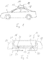
- a roof advertising medium 14 according to the invention is shown when used as intended on the roof of a taxi vehicle 15 .
- the roof advertising carrier 14 comprises a housing 16 which is arranged between two taxi signs 17, 18 pointing forwards and backwards. Advertisements on the side Surfaces of the housing 16 are shown, can be easily perceived by passers-by.
- the roof advertising carrier 14 includes according to 2 a base frame 19 on which two magnetic pads 20 are attached.
- the magnetic pads 20 adhere to the roof panel of the taxi vehicle 15 and ensure that the roof advertising medium 14 is securely fastened to the taxi vehicle 15.
- the housing 16 of the roof advertising carrier 14 is mounted pivotably relative to the base frame 19 .
- the housing 16 Connected to the housing 16 are two pivot pins 21, 22 which are rotatably received in two bearing seats located in 2 are covered by the taxi signs 17, 18.
- a pivoting movement of the housing 16 relative to the base frame 19 is shown in FIG 2 shown use state blocked by two locking levers 23 which are in engagement with locking pin 24.
- the housing 16 can be pivoted relative to the base frame 19 and in the 3 shown idle state.
- the taxi vehicle 15 can drive through a car wash, for example, without the roof advertising medium 14 being damaged.
- the cross-sectional view shown includes the housing 16 a plastic shell 26, which may consist of PMMA, for example.
- the plastic shell 26 forms the upper surface, the lower surface and the front and rear end faces of the housing 16.
- the plastic shell 26 has rectangular recesses in the two side surfaces, in each of which a Plexiglas pane 27, 31 is inserted.
- a graphic display 28, 29 is arranged behind each of the plexiglass panes 27, 31, see above that the image displayed by the graphic display 28, 29 is visible through the plexiglass pane 27, 31.
- the first graphic display 28 is enclosed between the first plexiglass pane 27, the adjoining areas of the plastic shell 26 and a first partition wall 30 made of aluminum arranged inside the housing 16.
- the first plexiglass pane 27, the first partition 30 and the associated areas of the plastic shell 26 form a closed envelope around the first graphic display 28.
- the cover 26, 27, 30 is tight, so that the graphic display 28 does not come into contact with either the outside air or moisture.
- the second graphic display 29 is enclosed in an enclosure made up of the second plexiglass pane 31, a second partition wall 32 and the associated sections of the plastic shell 26.
- a cavity 25 is enclosed between the first partition wall 30 and the second partition wall 32 .
- the roof advertising medium includes a cooling system that is constructed as follows.
- a first connection channel 33 and a second connection channel 34 are formed between the first partition wall 30 and the second partition wall 32 .
- a fan is arranged in each of the connecting ducts 33, 34, the first fan acting from the first partition 30 to the second partition 32 and the second fan works in the opposite direction. When both fans in the connecting channels 33, 34 are in operation, the result is a closed one
- the air flows over a large area along the partitions 30, 32, so that good heat transfer to the partitions 30, 32 is achieved .
- the fans in the connection channels 33, 34 are always in operation when the graphic displays 28, 29 are in operation.
- the blowers in the connecting channels 33, 34 are automatically put into operation even when the graphic displays 28, 29 are inactive if a certain temperature in the housing 16 is exceeded.
- the cavity 25 enclosed between the partition walls 30, 32 is part of a ventilation duct which extends longitudinally through the housing 16.
- the two taxi signs 17, 18 have an opening on their underside.
- the ventilation duct extends from the opening of the first taxi sign 17 through the interior of the pivot pin 21 into the cavity 25 in the housing 16.
- the ventilation duct further extends through the interior of the second pivot pin 22 and the second taxi sign 18 to the opening at lower end of the second taxi sign 18.
- the air stream results in a continuous flow of air along this ventilation duct.
- the airflow flows past the inside of the partitions 30, 32 so that the air on the partitions 30, 32 transferred heat is effectively dissipated to the outside with the air flow.
- the operating temperature of the graphic displays 28, 29 is kept within a permissible range.
- a blower 35 is arranged in the ventilation duct, which can generate an air flow along the ventilation duct.
- the blower 35 is controlled depending on the temperature, so that when it is exceeded a certain temperature inside the housing 16 is automatically put into operation.
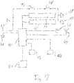
- the roof advertising medium includes a control unit 40 for controlling the graphic displays 28, 29.
- the control unit 40 reads a data record from a memory 41, which represents a graphic representation.
- the data set is sent to the graphic displays 28, 29 so that they display the graphic representation.
- the control unit 40 receives a signal from the switch 42 of the taxi vehicle 15 as soon as the ignition is switched on. The control unit 40 starts operating with this signal.
- a control program stored in the control unit 40 processes information received from a GPS module 43 about the current geographic position.
- the control program also processes information about the current time, the current weather and a weather forecast, which the control program receives via a radio data link 44 .
- the control program can decide which of the data records stored in memory 41 is to be selected for presentation on graphic displays 28, 29.
- control program selects a different data set for display on the graphic displays 28, 29, so that different advertisements are displayed in continuous alternation.
- the control program in the control unit 40 further processes information from a light sensor 45 on the current brightness in the vicinity of the roof advertising medium 14.
- the brightness of the graphic displays 28, 29 is adjusted so that the Advertisements can be seen well on the one hand and nobody is blinded on the other.
- the data sets stored in memory 41 are updated regularly.
- the radio data connection 44 is activated in order to transmit new data records from a server to the data store 41 .
- New specifications for the selection of the data sets can also be transmitted to the control unit 40 in the same way.
- the control unit 40 can be accessed via a USB port 49 for maintenance purposes.
- the control unit 40 is set up in such a way that, after the ignition 42 has been switched off, it keeps the graphic displays 28, 29 in operation for a run-on time of 15 minutes. After the run-on time has elapsed, the control unit 40 switches the graphic displays 28, 29 off. During the run-on time, the control unit 40 evaluates the signals from a voltage sensor 46 which monitors the voltage of the vehicle battery of the taxi vehicle 15 . If the voltage sensor 46 reports a voltage of less than 11.2 V, the graphic displays 28, 29 are already switched off before the follow-up time has elapsed. In this way, an excessive load on the vehicle battery is avoided.
- the lighting of the taxi signs 17, 18 is also controlled via the ignition switch 42 of the taxi vehicle 15.
- the lighting of the taxi signs 17, 18 is switched off when the ignition is off.
- the lighting of the taxi signs 17, 18 can be switched off by the driver via a switch 47 arranged in the interior of the taxi vehicle 15. Despite the switch 47 being switched on, the lighting remains off when the switch 48 is open. This is the case when the housing 16 is pivoted into the rest position. In the operating state of the housing 16, the switch 48 is closed.
- the lighting of the taxi signs 17, 18 is in Operation when the ignition is on and both switches 47, 48 are closed.
Landscapes
- Engineering & Computer Science (AREA)
- Physics & Mathematics (AREA)
- General Physics & Mathematics (AREA)
- Theoretical Computer Science (AREA)
- Mechanical Engineering (AREA)
- Business, Economics & Management (AREA)
- Accounting & Taxation (AREA)
- Marketing (AREA)
- General Engineering & Computer Science (AREA)
- Vehicle Waterproofing, Decoration, And Sanitation Devices (AREA)
Description
- Die Erfindung betrifft einen Dachwerbeträger für ein Fahrzeug. Ein solcher Werbeträger kann auf dem Dach eines Fahrzeugs angebracht werden, so dass sich eine oberhalb des Dachs angeordnete Werbefläche ergibt, siehe
EP 1 262 371 A2 . Solche Dachwerbeträger werden bislang mit austauschbaren Werbeplakaten bestückt. Das Bereitstellen und Wechseln der Werbeplakate ist mit einigem Aufwand verbunden. - Verwendet man zur Darstellung der Werbung ein Grafikdisplay statt der Werbeplakate, wird der logistische Aufwand vermindert. Allerdings sind die Einsatzbedingungen auf dem Dach eines Fahrzeugs nicht günstig für ein Grafikdisplay. Unter anderem wirken Erschütterungen und Witterungseinflüsse auf den Dachwerbeträger. Dokument
US2008/0236007 A1 stellt ein Anzeigesystem mit einer Anzeigeeinheit vor, wobei die Anzeigeeinheit in einem Gehäuse eingeschlossen ist, wobei das Gehäuse mit Lüftungskanalöffnungen versehen ist und, wobei die Anzeigeeinheit zwei nach außen gerichtete Anzeigetafeln beinhaltet. DokumentKR 101 490 218 B1 - Der Erfindung liegt die Aufgabe zugrunde, einen Dachwerbeträger vorzustellen, der die Verwendung eines Grafikdisplays ermöglicht. Ausgehend vom genannten Stand der Technik wird die Aufgabe gelöst mit den Merkmalen des Anspruchs 1. Vorteilhafte Ausführungsformen sind in den Unteransprüchen angegeben.
- Bei dem erfindungsgemäßen Dachwerbeträger wird ein Gehäuse von einem Grundrahmen getragen. In dem Gehäuse sind zwei Grafikdisplays angeordnet. Ein Lüftungskanal erstreckt sich durch das Gehäuse hindurch. Innerhalb des Gehäuses ist zwischen jedem Grafikdisplay und dem Lüftungskanal eine Trennwand angeordnet.
- Durch das Gehäuse kann das Grafikdisplay vor dem direkten Einfluss von Feuchtigkeit und Niederschlägen geschützt werden. Allerdings wird durch das Gehäuse auch die Möglichkeit der Wärmeabfuhr eingeschränkt, so dass das Risiko einer Überhitzung des Grafikdisplays besteht. Dies gilt insbesondere, wenn zusätzlich zu der Betriebswärme des Grafikdisplays eine Sonneneinstrahlung auf das Gehäuse einwirkt. Indem das Gehäuse mit einem Lüftungskanal ausgestattet ist, wird die Wärmeabfuhr verbessert, so dass die Betriebstemperatur des Grafikdisplays in einem zulässigen Bereich gehalten werden kann. Die erfindungsgemäße Trennwand hat den Vorteil, dass ein direkter Kontakt zwischen dem Grafikdisplay und der einströmende Außenluft vermieden wird.
- Der Lüftungskanal kann sich von einem Eintritt in das Gehäuse bis zu einem Austritt aus dem Gehäuse erstrecken. Der Eintritt und der Austritt des Lüftungskanals können an gegenüberliegenden Enden des Gehäuses angeordnet sein, so dass der Lüftungskanal sich über die gesamte Ausdehnung des Gehäuses zwischen diesen beiden Enden erstreckt.
- Der Eintritt des Lüftungskanals kann in Fahrtrichtung ausgerichtet sein, wenn der Dachwerbeträger bestimmungsgemäß auf dem Fahrzeug angebracht ist. Der Austritt des Lüftungskanals kann entgegen der Fahrtrichtung ausgerichtet sein. Auf diese Weise kann mit dem Fahrtwind ein Luftstrom durch den Lüftungskanal erzeugt werden. Alternativ oder zusätzlich dazu kann ein Gebläse vorgesehen sein, mit dem unabhängig von einer Bewegung des Fahrzeugs ein Luftstrom durch den Lüftungskanal erzeugt werden kann. Das Gebläse kann temperaturgesteuert sein und beispielsweise in Gang gesetzt werden, wenn ein vorgegebener Temperatur-Schwellwert innerhalb des Gehäuses überschritten wird. Zum Ermitteln der Temperatur kann der erfindungsgemäße Dachwerbeträger einen in dem Gehäuse angeordneten Temperatursensor umfassen.
- Jede Trennwand zwischen einem der Grafikdisplays und dem Lüftungskanal kann so gestaltet sein, dass sie zusammen mit einem Abschnitt des Gehäuses eine Umhüllung für das Grafikdisplay bildet. Eine solche Trennwand hat den Vorteil, dass ein direkter Kontakt zwischen dem Grafikdisplay und der einströmende Außenluft vermieden wird. Für eine gute Wärmeabfuhr kann die Trennwand aus einem Material mit guter Wärmeleitfähigkeit bestehen. Die Trennwand kann beispielsweise aus Aluminium gefertigt sein. Die aus der Trennwand und dem Gehäuseabschnitt gebildete Umhüllung des Grafikdisplays ist vorzugsweise so gestaltet, dass ein Eintritt von Feuchtigkeit in die Umhüllung ausgeschlossen ist.
- Für die Wärmeabfuhr ist es von Vorteil, wenn Luft in der Grafikdisplay-Umhüllung in Bewegung versetzt werden kann. Der erfindungsgemäße Dachwerbeträger kann ein Gebläse umfassen, um eine Luftbewegung innerhalb der Umhüllung anzutreiben. Die in der Umhüllung angeordnete Luft ist vorzugsweise getrennt von der Luft in dem Lüftungskanal.
- Der erfindungsgemäße Dachwerbeträger umfasst ein erstes Grafikdisplay und ein zweites Grafikdisplay. Beide Grafikdisplays sind innerhalb des Gehäuses angeordnet. Die Grafikdisplays können in verschiedenen Richtungen ausgerichtet sein. Die Grafikdisplays können bezogen auf eine horizontale Dimension und/oder eine vertikale Dimension parallel zueinander ausgerichtet sein. Dabei können die Grafikdisplays nach außen ausgerichtet sein, so dass die angezeigten Inhalte von unterschiedlichen Seiten des Fahrzeugs aus betrachtet werden können.
- Zwischen den Grafikdisplays ist ein Hohlraum ausgebildet. Der Hohlraum ist im Inneren des Gehäuses angeordnet. Der Lüftungskanal erstreckt sich durch den Hohlraum hindurch. Damit kann eine wirksame Kühlung von elektronischen Bauteilen erreicht werden, die auf der Rückseite der Grafikdisplays angeordnet sind.
- Der Hohlraum ist zwischen zwei Trennwänden eingeschlossen. Jede der Trennwände kann Element einer Umhüllung für eines der Grafikdisplays sein. Das Gehäuse umfasst demnach zwei Umhüllungen, wobei in jeder Umhüllung eines der Grafikdisplays angeordnet ist. Zwischen den Umhüllungen ist der Hohlraum des Gehäuses eingeschlossen.
- Zwischen dem Innenraum der ersten Umhüllung und dem Innenraum der zweiten Umhüllung kann ein Verbindungskanal ausgebildet sein. Der Verbindungskanal kann den Hohlraum des Gehäuses queren. Durch einen solchen Verbindungskanal wird ein Luftaustausch zwischen dem Innenraum der ersten Umhüllung und dem Innenraum der zweiten Umhüllung ermöglicht.
- Es können ein erster Verbindungskanal und ein zweiter Verbindungskanal zwischen den Umhüllungen ausgebildet sein. Durch zwei Verbindungskanäle wird die Möglichkeit eröffnet, die Luft zwischen den Innenräumen der Umhüllungen in einem Kreislauf auszutauschen. Es kann ein Gebläse vorgesehen sein, um die Luft in Bewegung zu halten. Das Gebläse kann in einem Verbindungskanal angeordnet sein.
- In einer Ausführungsform der Erfindung ist in dem ersten Verbindungskanal ein erstes Gebläse und in dem zweiten Verbindungskanal ein zweites Gebläse angeordnet. Das erste Gebläse kann von der ersten Umhüllung in Richtung der zweiten Umhüllung wirken, das zweite Gebläse kann von der zweiten Umhüllung in Richtung der ersten Umhüllung wirken. Auf diese Weise kann ein geschlossener Luftkreislauf zwischen der ersten Umhüllung und der zweiten Umhüllung erzeugt werden.
- Die Trennwände, an denen der Luftkreislauf entlang strömt, können als Kühlelemente dienen. Durch den Luftkreislauf findet eine Wärmeübertragung von den elektronischen Bauteilen der Grafikdisplays auf die Trennwände statt. Die gegenüberliegenden Seiten der Trennwände können an den Lüftungskanal angrenzen, der sich durch das Gehäuse hindurch erstreckt. Durch den Luftstrom in dem Lüftungskanal wird die Wärme von den Trennwänden aufgenommen und nach außen abgeführt. Diese Weise kann eine wirksame Kühlung der Grafikdisplays erreicht werden, ohne dass die Grafikdisplays in einen direkten Kontakt mit der Au-ßenluft kommen.
- Das Gehäuse des erfindungsgemäßen Dachwerbeträgers kann über eine bewegliche Verbindung an dem Grundrahmen befestigt sein. In einem Nutzzustand kann das Gehäuse eine aufrechte Position haben, so dass das Grafikdisplay zur Seite weist. In einem Ruhezustand kann das Gehäuse eine liegende Position haben. In dem Ruhezustand kann das Grafikdisplay so angeordnet sein, dass es für Passanten nicht sichtbar ist und beispielsweise in einer liegenden Position sein. Von dem Ruhezustand kann beispielsweise Gebrauch gemacht werden, um Schäden an dem Dachwerbeträger zu vermeiden, wenn das Fahrzeug durch eine Waschanlage fährt.
- Für den Wechsel zwischen dem Nutzzustand und dem Ruhezustand kann ein Schwenkgelenk zwischen dem Gehäuse und dem Grundrahmen vorgesehen sein. Die Achse des Schwenkgelenks kann horizontal ausgerichtet sein und sich parallel zu dem Grafikdisplays erstrecken.
- Der Dachwerbeträger kann einen Verriegelungsmechanismus umfassen, um das Gehäuse in dem Nutzzustand zu arretieren. Der Verriegelungsmechanismus kann einen Verriegelungshebel umfassen, der einen Zapfen umgreift. Der Zapfen kann mit dem Gehäuse verbunden sein, der Verriegelungshebel kann mit dem Grundrahmen verbunden sein. Der Dachwerbeträger kann so eingerichtet sein, dass das Gehäuse im Ruhezustand alleine aufgrund der Gewichtskraft eine stabile Position einnimmt.
- Das Schwenkgelenk kann einen die Schwenkachse definierenden Schwenkzapfen umfassen. Der Lüftungskanal kann sich durch das Innere des Schwenkzapfens hindurch erstrecken. Insbesondere ist es möglich, dass das Schwenkgelenk einen ersten Schwenkzapfen und einen zweiten Schwenkzapfen umfasst. Die Schwenkzapfen können an gegenüberliegenden Enden des Gehäuses angeordnet sein. Wenn der Lüftungskanal sich durch den ersten Schwenkzapfen und den zweiten Schwenkzapfen hindurch erstreckt, kann der Lüftungskanal die gesamte Länge zwischen diesen beiden Enden des Gehäuses abdecken.
- Der Dachwerbeträger kann ein Taxischild umfassen. Taxischilder sind üblicherweise so angeordnet, dass sie entweder zum Front oder zum Heck des Fahrzeugs weisen. Eine horizontale Achse des Taxischilds kann mit einer horizontalen Achse des Grafikdisplays einen rechten Winkel einschließen, wenn das Gehäuse im Nutzzustand ist.
- Der Dachwerbeträger kann ein erstes Taxischild und ein zweites Taxischild umfassen. Das erste Taxischild kann nach vorne weisen, das zweite Taxischild kann nach hinten weisen. Das Gehäuse des erfindungsgemäßen Dachwerbeträgers kann zwischen dem ersten Taxischild und dem zweiten Taxischild angeordnet sein.
- Ein Taxischild kann so angeordnet sein, dass es den Eintritt des Lüftungskanals abdeckt. Das zweite Taxischild kann so angeordnet sein, dass es den Austritt des Lüftungskanals abdeckt. Dies hat den Vorteil, dass der Lüftungskanal dem Fahrtwind nur indirekt ausgesetzt ist, so dass beispielsweise ein Eindringen von Regenwasser in den Lüftungskanal vermieden werden kann.
- Der Dachwerbeträger kann eine Beleuchtung für das Taxischild umfassen, die dazu ausgelegt ist, mit einem Schalter aus dem Innenraum des Fahrzeugs betätigt zu werden. Die Beleuchtung kann inaktiviert werden, wenn das Gehäuse im Ruhezustand ist. Im inaktiven Zustand ist die Beleuchtung ausgeschaltet unabhängig davon, in welcher Stellung der Schalter im Innenraum des Fahrzeugs ist. Auf diese Weise kann sichergestellt werden, dass der Fahrer das Gehäuse mit den Grafikdisplays immer in den Nutzzustand bringt, wenn das Taxi im Einsatz ist. Ein Dachwerbeträger, bei dem die Beleuchtung eines Taxischilds inaktiviert wird, wenn das Gehäuse im Ruhezustand ist, hat eigenständigen erfinderischen Gehalt, auch ohne dass sich ein Lüftungskanal durch das Gehäuse hindurch erstreckt.
- Der Grundrahmen kann eine Befestigungseinrichtung umfassen, um den erfindungsgemäßen Dachwerbeträger auf dem Dach eines Fahrzeugs anbringen zu können. Die Befestigungseinrichtung kann magnetische Pads umfassen, die auf dem Dachblech des Fahrzeugs haften, ohne den Lack zu zerkratzen. Möglich sind auch andere Arten von Verbindungen zwischen dem Dachwerbeträger und dem Fahrzeug, beispielsweise Klebeverbindungen oder mechanische Verbindungen.
- Ein Grafikdisplay im Sinne der Erfindung ist dazu ausgelegt, ein in Datenform gespeichertes Bild anzuzeigen. Der Dachwerbeträger kann einen Speicher umfassen, in dem eines oder mehrere Bilder gespeichert sind. Mit einer Steuereinheit kann eingestellt werden, welche Bilder für wie lange gezeigt werden und zu welchen Zeitpunkten zwischen den Bildern gewechselt wird. Umfasst der Dachwerbeträger zwei Grafikdisplays, so können diese gleiche Bilder oder verschiedene Bilder anzeigen.
- Das Grafikdisplay kann beispielsweise eine horizontale Länge zwischen 80 cm und 120 cm haben sowie eine vertikale Höhe zwischen 15 cm und 40 cm. Die Helligkeit des Grafikdisplays kann einstellbar sein. Die maximale Helligkeit des Grafikdisplays kann beispielsweise zwischen 800 Candela/m2 und 2500 Candela/m2 liegen.
- Die Versorgung des Grafikdisplays kann über das Stromnetz des Fahrzeugs erfolgen. Entsprechende Versorgungskabel können sich zwischen dem Stromnetz des Fahrzeugs und dem Dachwerbeträger erstrecken. Die Versorgungskabel können durch das Innere eines Schwenkzapfens in den Innenraum des Gehäuses geführt sein.
- Das Grafikdisplay kann über die Zündung des Fahrzeugs angesteuert werden. Insbesondere kann das Grafikdisplay durch Anschalten der Zündung aktiviert werden. Möglich ist, das Grafikdisplay mit dem Ausschalten der Zündung wieder zu aktivieren. In einer Ausführungsform ist eine Nachlaufzeit vorgesehen, so dass das Grafikdisplay auch nach dem Ausschalten der Zündung aktiv bleibt. Die Nachlaufzeit kann beispielsweise zwischen 5 Minuten und 30 Minuten, vorzugsweise zwischen 10 Minuten und 20 Minuten lang sein.
- Wird das Grafikdisplay über die Batterie des Fahrzeugs betrieben, so kann ein Sensor vorgesehen sein, der ein Abschaltsignal an das Grafikdisplay sendet, wenn die Batterieladung unter einen vorgegebenen Schwellwert absinkt. Der Sensor kann beispielsweise ein Spannungssensor sein und ein Abschaltsignal geben, wenn die Batteriespannung unter 11,2 V absinkt.
- Der Dachwerbeträger kann dazu ausgelegt sein, die in dem Speicher zu speichernden Bilder über eine Funk-Datenverbindung zu empfangen. Ebenso kann das Steuerungsprogramm, mit dem die Abfolge der Bilder definiert wird, über eine Funk-Datenverbindung empfangen werden. Die Datenübertragung kann über ein Mobilfunknetz erfolgen. Der Dachwerbeträger kann eine SIM-Karte für die Verbindung mit dem Mobilfunknetz umfassen.
- Der Speicher für die Daten und die Steuereinheit können innerhalb des Gehäuses angeordnet sein. Die Antenne für die Funk-Datenverbindung kann außerhalb des Gehäuses angeordnet sein. Eine Kabelverbindung zwischen der Antenne und dem Innenraum des Gehäuses kann durch das Innere eines Schwenkzapfens des Gehäuses hindurch geführt sein.
- Zusätzlich oder alternativ zu der Funk-Datenverbindung kann ein kabelgebundener Anschluss für das Übertragen von Daten vorgesehen sein. Beispielweise kann die Datenübertragung über eine USB-Steckverbindung erfolgen. Der Stecker der Kabelverbindung kann außerhalb des Gehäuses angeordnet sein. Die Kabelverbindung in den Innenraum des Gehäuses kann durch das Innere eines Schwenkzapfens des Gehäuses hindurch geführt sein.
- Der Dachwerbeträger kann so ausgelegt sein, dass die Funk-Datenverbindung für die im normalen Betrieb des Dachwerbeträgers auszutauschenden Daten genutzt wird. Die kabelgebundene Datenverbindung kann für Wartungszwecke genutzt werden.
- Das Grafikdisplay kann so eingerichtet sein, dass die Helligkeit der Anzeige in Abhängigkeit von einem Steuersignal variiert werden kann. Damit wird es möglich, die Helligkeit der Grafikdisplays an die Umgebungshelligkeit anzupassen. Beispielweise kann das Grafikdisplay tagsüber mit größerer Helligkeit betrieben werden als bei Dunkelheit.
- Das Steuersignal für die Helligkeit der Grafikdisplays kann von einem Lichtsensor stammen, der die Helligkeit in der Umgebung des Dachwerbeträgers misst. Möglich ist auch, dass das Steuersignal von einer Steuereinheit generiert wird, die Informationen wie Tageszeit, Wetterbedingungen und Ähnliches verarbeitet, um das Steuersignal zu erzeugen.
- Der Dachwerbeträger kann ein Modul zur geographischen Ortung umfassen, beispielsweise in Form eines GPS-Moduls. Damit wird es möglich Bewegungsprofile des Fahrzeugs aufzuzeichnen. In Kombination mit der ebenfalls gespeicherten Information, welche Bilder das Grafikdisplays zu welcher Zeit dargestellt hat, können den Werbekunden umfassen Informationen über die tatsächlich erfolgte Werbung zur Verfügung gestellt werden.
- Möglich ist auch, das Grafikdisplay in Abhängigkeit von der geographischen Position des Dachwerbeträgers anzusteuern. Beispielsweise kann die Anzeige eines Werbekunden, der nur in einem Lokal eng begrenzten Umfeld tätig ist, nur dann eingeblendet werden, wenn der Dachwerbeträger in dem relevanten geographischen Gebiet ist.
- Zusätzlich oder alternativ dazu kann das Grafikdisplay zeitabhängig angesteuert werden. Werden bestimmte Produkte oder Dienstleistungen bevorzugt zu bestimmten Tageszeiten gekauft, so können die zugehörigen Werbeanzeigen zu passenden Tageszeiten eingeblendet werden.
- Zusätzlich oder alternativ dazu kann das Grafikdisplay wetterabhängig angesteuert werden. Werbeanzeigen für Produkte, die in erster Linie bei bestimmten Wetterbedingungen gekauft werden, können zu passender Zeit dargestellt werden. Der Dachwerbeträger kann Wettersensoren umfassen, beispielsweise für die Temperatur oder die Luftfeuchtigkeit. Eine Steuereinheit kann dazu ausgelegt sein, die Messwerte der Wettersensoren zu verarbeiten, um daraus ein Steuersignal für das Grafikdisplay abzuleiten, gemäß dem das Grafikdisplay eine bestimmte Werbeanzeige darstellt. Zusätzlich oder alternativ dazu kann die Steuereinheit dazu ausgelegt sein, Wetterdaten über eine Funk-Datenverbindung zu empfangen. Die Wetterdaten können aktuelle Wetterdaten oder Prognosedaten sein. Ermittelt die Steuereinheit das Steuersignal für das Grafikdisplay unter Berücksichtigung von Prognosedaten, so wird die Möglichkeit eröffnet, beim Einblenden von Werbeanzeigen die zukünftige Wetterentwicklung einfließen zu lassen.
- Ein Dachwerbeträger, bei dem eine Steuereinheit ein Grafikdisplay wetterabhängig, zeitabhängig und/oder abhängig von der geographischen Position ansteuert, hat eigenständigen erfinderischen Gehalt, auch ohne dass ein Lüftungskanal sich durch das Gehäuse des Werbeträgers hindurch erstreckt. Ansteuern in diesem Sinne bedeutet, dass ein Grafikdisplay angewiesen wird, die in einem bestimmten Datensatz enthaltene grafische Information anzuzeigen. Die Erfindung betrifft außerdem ein Verfahren, bei dem ein Grafikdisplay eines Dachwerbeträgers wetterabhängig, zeitabhängig und/oder abhängig von der geographischen Position angesteuert wird. Das Verfahren kann mit weiteren Merkmalen fortgebildet werden, die im Zusammenhang des erfindungsgemäßen Dachwerbeträgers beschrieben sind.
- Die Erfindung wird nachfolgend unter Bezugnahme auf die beigefügten Zeichnungen anhand vorteilhafter Ausführungsformen beispielhaft beschrieben. Es zeigen:
- Fig. 1:
- einen erfindungsgemäßen Dachwerbeträger bei bestimmungsgemäßer Verwendung;
- Fig. 2:
- einen erfindungsgemäßen Dachwerbeträger im Nutzzustand;
- Fig. 3:
- den Dachwerbeträger aus
Fig. 2 im Ruhezustand; - Fig. 4:
- eine schematische Schnittdarstellung des Dachwerbeträgers aus
Fig. 2 ; - Fig. 5:
- einen Vertikalschnitt in Querrichtung durch ein Gehäuse eines erfindungsgemäßen Dachwerbeträgers in vergrößerter Darstellung;
- Fig. 6:
- einen Horizontalschnitt durch ein Gehäuse eines erfindungsgemäßen Dachwerbeträgers;
- Fig. 7:
- ein Blockschaltbild eines erfindungsgemäßen Dachwerbeträgers.
- In
Fig. 1 ist ein erfindungsgemäßer Dachwerbeträger 14 bei bestimmungsgemäßer Verwendung auf dem Dach eines Taxifahrzeugs 15 gezeigt. Der Dachwerbeträger 14 umfasst ein Gehäuse 16, das zwischen zwei nach vorne und hinten weisenden Taxischildern 17, 18 angeordnet ist. Werbeanzeigen, die auf den seitlichen Flächen des Gehäuses 16 gezeigt werden, können von Passanten gut wahrgenommen werden. - Der Dachwerbeträger 14 umfasst gemäß
Fig. 2 einen Grundrahmen 19, an dem zwei Magnetpads 20 angebracht sind. Die Magnetpads 20 haften auf dem Dachblech des Taxifahrzeugs 15 und sorgen für eine sichere Befestigung des Dachwerbeträgers 14 an dem Taxifahrzeug 15. - Das Gehäuse 16 des Dachwerbeträgers 14 ist schwenkbar relativ zu dem Grundrahmen 19 gelagert. Mit dem Gehäuse 16 sind zwei Schwenkzapfen 21, 22 verbunden, die drehbar in zwei Lageraufnahmen aufgenommen sind, die in
Fig. 2 durch die Taxischilder 17, 18 verdeckt sind. Eine Schwenkbewegung des Gehäuses 16 relativ zu dem Grundrahmen 19 ist in dem inFig. 2 gezeigten Nutzzustand blockiert durch zwei Verriegelungshebel 23, die in Eingriff mit Verriegelungszapfen 24 stehen. - Nach Lösen des Verriegelungsmechanismus 23, 24 kann das Gehäuse 16 relativ zu dem Grundrahmen 19 geschwenkt werden und in den in
Fig. 3 gezeigten Ruhezustand gebracht werden. Im Ruhezustand kann das Taxifahrzeug 15 beispielsweise durch eine Waschanlage fahren, ohne dass der Dachwerbeträger 14 Schaden nimmt. - Gemäß der in
Fig. 5 gezeigten Querschnittsdarstellung umfasst das Gehäuse 16 eine Plastikschale 26, die beispielsweise aus PMMA bestehen kann. Die Plastikschale 26 bildet die obere Fläche, die untere Fläche und die vordere und hintere Stirnfläche des Gehäuses 16. In den beiden Seitenflächen hat die Plastikschale 26 rechteckige Ausnehmungen, in die jeweils eine Plexiglasscheibe 27, 31 eingesetzt ist. Hinter jeder der Plexiglasscheiben 27, 31 ist ein Grafikdisplay 28, 29 angeordnet, so dass das von dem Grafikdisplay 28, 29 angezeigte Bild durch die Plexiglasscheibe 27, 31 hindurch sichtbar ist. - Das erste Grafikdisplay 28 ist eingeschlossen zwischen der ersten Plexiglasscheibe 27, den angrenzenden Bereichen der Plastikschale 26 sowie einer im Inneren des Gehäuses 16 angeordneten ersten Trennwand 30 aus Aluminium. Die erste Plexiglasscheibe 27, die erste Trennwand 30 und die zugehörigen Bereiche der Plastikschale 26 bilden eine geschlossene Umhüllung um das erste Grafikdisplay 28 herum. Die Umhüllung 26, 27, 30 ist dicht, so dass das Grafikdisplay 28 weder mit der Außenluft noch mit Feuchtigkeit in Berührung kommt.
- Auf entsprechende Weise ist das zweite Grafikdisplay 29 in eine Umhüllung aus der zweiten Plexiglasscheibe 31, einer zweiten Trennwand 32 und den zugehörigen Abschnitten der Plastikschale 26 eingeschlossen. Zwischen der ersten Trennwand 30 und der zweiten Trennwand 32 ist ein Hohlraum 25 eingeschlossen.
- Die von den Grafikdisplays 28, 29 erzeugte Betriebswärme wird in erster Linie in den Innenraum der Umhüllungen abgegeben. Um die Wärme wirksam nach außen zu transportieren und eine Überhitzung der Grafikdisplays 28, 29 zu vermeiden, umfasst der erfindungsgemäße Dachwerbeträger ein Kühlsystem, das wie folgt aufgebaut ist.
- Zwischen der ersten Trennwand 30 und der zweiten Trennwand 32 sind ein erster Verbindungskanal 33 und ein zweiter Verbindungskanal 34 ausgebildet. In jedem der Verbindungskanäle 33, 34 ist ein Gebläse angeordnet, wobei das erste Gebläse von der ersten Trennwand 30 zu der zweiten Trennwand 32 wirkt und das zweite Gebläse in entgegengesetzte Richtung wirkt. Wenn beide Gebläse in den Verbindungskanälen 33, 34 in Betrieb sind, ergibt sich ein geschlossener
- Luftkreislauf zwischen dem Innenraum der ersten Umhüllung 26, 27, 30 und dem Innenraum der zweiten Umhüllung 26, 31, 32. Insbesondere streicht die Luft großflächig an den Trennwänden 30, 32 entlang, so dass eine gute Wärmeüberleitung auf die Trennwände 30, 32 erreicht wird. Die Gebläse in den Verbindungskanälen 33, 34 sind immer in Betrieb, wenn die Grafikdisplays 28, 29 in Betrieb sind. Zusätzlich werden die Gebläse in den Verbindungskanälen 33, 34 auch bei inaktiven Grafikdisplays 28, 29 automatisch in Betrieb gesetzt, wenn eine bestimmte Temperatur in dem Gehäuse 16 überschritten wird.
- Der zwischen den Trennwänden 30, 32 eingeschlossene Hohlraum 25 ist Bestandteil eines Lüftungskanals, der sich längs durch das Gehäuse 16 hindurch erstreckt. Gemäß
Fig. 4 haben die beiden Taxischilder 17, 18 an ihrer Unterseite eine Öffnung. Der Lüftungskanal erstreckt sich von der Öffnung des ersten Taxischilds 17 durch das Innere des Schwenkzapfens 21 hindurch in den Hohlraum 25 in dem Gehäuse 16. Der Lüftungskanal erstreckt sich weiter durch das Innere des zweiten Schwenkzapfens 22 und das zweite Taxischild 18 hindurch bis zu der Öffnung am unteren Ende des zweiten Taxischilds 18. - Ist das Taxifahrzeug 15 in Bewegung, ergibt sich durch den Fahrtwind ein kontinuierlicher Luftstrom entlang diesem Lüftungskanal. Der Luftstrom strömt an der Innenseite der Trennwände 30, 32 vorbei so dass die auf die Trennwände 30, 32 übertragene Wärme mit dem Luftstrom wirksam nach außen abgeführt wird. Dadurch wird die Betriebstemperatur der Grafikdisplays 28, 29 in einem zulässigen Bereich gehalten.
- Um eine wirksame Kühlung auch dann möglich zu machen, wenn das Taxifahrzeug 15 steht und kein Fahrtwind wirkt, ist in dem Lüftungskanal ein Gebläse 35 angeordnet, das einen Luftstrom entlang dem Lüftungskanal erzeugen kann. Das Gebläse 35 wird temperaturabhängig angesteuert, so dass es bei Überschreiten einer bestimmten Temperatur im Inneren des Gehäuses 16 automatisch in Betrieb gesetzt wird.
- Gemäß
Fig. 7 umfasst der Dachwerbeträger eine Steuereinheit 40 zur Ansteuerung der Grafikdisplays 28, 29. Die Steuereinheit 40 liest aus einem Speicher 41 einen Datensatz aus, der eine grafische Darstellung repräsentiert. Der Datensatz wird an die Grafikdisplays 28, 29 gesendet, so dass diese die grafische Darstellung anzeigen. Die Steuereinheit 40 erhält ein Signal von dem Schalter 42 des Taxifahrzeugs 15, sobald die Zündung eingeschaltet ist. Mit diesem Signal nimmt die Steuereinheit 40 ihren Betrieb auf. - Ein in der Steuereinheit 40 hinterlegtes Steuerprogramm verarbeitet eine von einem GPS-Modul 43 erhaltene Information über die aktuelle geographische Position. Das Steuerprogramm verarbeitet außerdem Informationen über die aktuelle Zeit, das aktuelle Wetter sowie eine Wetterprognose, die das Steuerprogramm über eine Funk-Datenverbindung 44 erhält. Auf Basis dieser Informationen kann das Steuerprogramm entscheiden, welche der in dem Speicher 41 hinterlegten Datensätze für die Darstellung auf den Grafikdisplays 28, 29 auszuwählen ist.
- Nachdem ein bestimmtes Bild für eine vorgegebene Zeitdauer angezeigt wurde, wählt das Steuerprogramm einen anderen Datensatz für die Anzeige auf den Grafikdisplays 28, 29 aus, so dass im laufenden Wechsel unterschiedliche Werbeanzeigen dargestellt werden.
- Das Steuerprogramm in der Steuereinheit 40 verarbeitet weiter eine Information von einem Lichtsensor 45 über die aktuelle Helligkeit in der Umgebung des Dachwerbeträgers 14. Die Helligkeit der Grafikdisplays 28, 29 wird so angepasst, dass die Werbeanzeigen einerseits gut wahrgenommen werden können und andererseits niemand geblendet wird.
- Die in dem Speicher 41 hinterlegten Datensätze werden regelmäßig aktualisiert. Dazu wird die Funk-Datenverbindung 44 aktiviert, um neue Datensätze von einem Server zu dem Datenspeicher 41 zu übertragen. Auf dem gleichen Wege können auch neue Vorgaben für die Auswahl der Datensätze an die Steuereinheit 40 übertragen werden. Über einen USB-Anschluss 49 kann zu Wartungszwecken auf die Steuereinheit 40 zugegriffen werden.
- Die Steuereinheit 40 ist so eingerichtet, dass sie nach Ausschalten der Zündung 42 die Grafikdisplays 28, 29 für eine Nachlaufzeit von 15 Minuten in Betrieb hält. Nach Ablauf der Nachlaufzeit schaltet die Steuereinheit 40 die Grafikdisplays 28, 29 aus. Während der Nachlaufzeit wertet die Steuereinheit 40 die Signale von einem Spannungssensor 46 aus, der die Spannung der Fahrzeugbatterie des Taxifahrzeugs 15 überwacht. Meldet der Spannungssensor 46 eine Spannung von weniger als 11,2 V, so werden die Grafikdisplays 28, 29 schon vor Ablauf der Nachlaufzeit ausgeschaltet. Auf diese Weise wird eine übermäßige Belastung der Fahrzeugbatterie vermieden.
- Die Beleuchtung der Taxischilder 17, 18 wird ebenfalls über den Zündungsschalter 42 des Taxifahrzeug 15 angesteuert. Die Beleuchtung der Taxischilder 17, 18 ist ausgeschaltet, wenn die Zündung aus ist. Bei eingeschalteter Zündung kann die Beleuchtung der Taxischilder 17, 18 vom Fahrer über einen im Innenraum des Taxifahrzeugs 15 angeordneten Schalter 47 ausgeschaltet werden. Trotz eingeschaltetem Schalter 47 bleibt die Beleuchtung aus, wenn der Schalter 48 geöffnet ist. Dies ist der Fall, wenn das Gehäuse 16 in den Ruhezustand geschwenkt ist. Im Betriebszustand des Gehäuses 16 ist der Schalter 48 geschlossen. Die Beleuchtung der Taxischilder 17, 18 ist in Betrieb, wenn die Zündung eingeschaltet ist und beide Schalter 47, 48 geschlossen sind.
Claims (14)
- Dachwerbeträger für ein Fahrzeug (15) mit einem Grundrahmen (19), der ein Gehäuse (16) trägt, und mit zwei in dem Gehäuse (16) angeordneten Grafikdisplays (28, 29), wobei ein Lüftungskanal vorgesehen ist, der sich durch das Gehäuse (16) hindurch erstreckt, dadurch gekennzeichnet, dass innerhalb des Gehäuses (16) eine erste Trennwand (30) zwischen dem ersten Grafikdisplay (28) und dem Lüftungskanal und eine zweite Trennwand (32) zwischen dem zweiten Grafikdisplay (29) und dem Lüftungskanal angeordnet sind, wobei der Lüftungskanal sich durch einen Hohlraum (25) hindurch erstreckt, der zwischen den zwei Trennwänden (30,32) ausgebildet ist.
- Dachwerbeträger nach Anspruch 1, dadurch gekennzeichnet, dass der Eintritt (21) und der Austritt (22) des Lüftungskanals an gegenüberliegenden Enden des Gehäuses (16) angeordnet sind.
- Dachwerbeträger nach Anspruch 1 oder 2, gekennzeichnet durch ein Gebläse (35) um einen Luftstrom in dem Lüftungskanal in Bewegung zu versetzen.
- Dachwerbeträger nach einem der Ansprüche 1-3, dadurch gekennzeichnet, dass die Trennwände (30, 32) zusammen mit einem Abschnitt (26, 27, 31) des Gehäuses (16) eine Umhüllung für die Grafikdisplays (28, 29) bildet.
- Dachwerbeträger nach Anspruch 4, gekennzeichnet durch eine erste Umhüllung (26, 27, 30) für das erste Grafikdisplay (28) und eine zweite Umhüllung (26, 31, 32) für das zweite Grafikdisplay (29) und durch einen zwischen der ersten Umhüllung (26, 27, 30) und der zweiten Umhüllung (26, 31, 32) angeordneten Hohlraum (25).
- Dachwerbeträger nach Anspruch 5, gekennzeichnet durch einen geschlossenen Luftkreislauf zwischen der ersten Umhüllung (26, 27, 30) und der zweiten Umhüllung (26, 31, 32) .
- Dachwerbeträger nach einem der Ansprüche 1 bis 6, dadurch gekennzeichnet, dass das Gehäuse (16) relativ zu dem Grundrahmen (19) zwischen einem Nutzzustand und einem Ruhezustand schwenkbar ist.
- Dachwerbeträger nach Anspruch 7, dadurch gekennzeichnet, dass der Lüftungskanal sich durch das Innere eines eine Schwenkachse definierenden Schwenkzapfens (21, 22) hindurch erstreckt.
- Dachwerbeträger nach einem der Ansprüche 1 bis 8, gekennzeichnet durch ein Taxischild (17, 18), wobei eine Beleuchtung des Taxischilds (17, 18) von einem Schalter (48) abhängt, der durch eine Bewegung des Gehäuses (16) relativ zu dem Grundrahmen (19) betätigt wird.
- Dachwerbeträger nach einem der Ansprüche 1 bis 9, dadurch gekennzeichnet, dass eines oder mehrere elektrische Anschlusskabel des Dachwerbeträgers durch das Innere eines Schwenkzapfens (21, 22) hindurch geführt sind.
- Dachwerbeträger nach einem der Ansprüche 1 bis 10, dadurch gekennzeichnet, dass die Grafikdisplays (28, 29) nach dem Ausschalten der Zündung des Fahrzeugs für eine Nachlaufzeit in Betrieb gehalten werden.
- Dachwerbeträger nach Anspruch 11, dadurch gekennzeichnet, dass die Grafikdisplays (28, 29) während der Nachlaufzeit inaktiviert werden, wenn die Batteriespannung des Fahrzeugs unter einen vorgegebenen Schwellwert absinkt.
- Dachwerbeträger nach einem der Ansprüche 1 bis 12, dadurch gekennzeichnet, dass die Helligkeit des Grafikdisplays (28, 29) in Abhängigkeit von der Umgebungshelligkeit gesteuert wird.
- Dachwerbeträger nach einem der Ansprüche 1 bis 13, dadurch gekennzeichnet, dass eine Steuereinheit (40) die Grafikdisplays (28, 29) wetterabhängig, zeitabhängig und/oder abhängig von der geographischen Position ansteuert.
Applications Claiming Priority (1)
| Application Number | Priority Date | Filing Date | Title |
|---|---|---|---|
| DE102017213283.3A DE102017213283A1 (de) | 2017-08-01 | 2017-08-01 | Dachwerbeträger für ein Fahrzeug |
Publications (2)
| Publication Number | Publication Date |
|---|---|
| EP3438959A1 EP3438959A1 (de) | 2019-02-06 |
| EP3438959B1 true EP3438959B1 (de) | 2022-12-07 |
Family
ID=62981079
Family Applications (1)
| Application Number | Title | Priority Date | Filing Date |
|---|---|---|---|
| EP18183926.7A Active EP3438959B1 (de) | 2017-08-01 | 2018-07-17 | Dachwerbeträger für ein fahrzeug |
Country Status (2)
| Country | Link |
|---|---|
| EP (1) | EP3438959B1 (de) |
| DE (1) | DE102017213283A1 (de) |
Families Citing this family (3)
| Publication number | Priority date | Publication date | Assignee | Title |
|---|---|---|---|---|
| DE102019107918A1 (de) * | 2019-03-27 | 2020-10-01 | Uze! Mobility Gmbh | Display-Vorrichtung für Kraftfahrzeuge |
| US12202502B2 (en) | 2020-11-30 | 2025-01-21 | Uze! Mobility Gmbh | Apparatus for displaying information on a vehicle |
| EP4119396B1 (de) * | 2021-07-15 | 2024-05-08 | Uze! Mobility GmbH | Vorrichtung zur montage an einem fahrzeugdach und zur informationsanzeige |
Family Cites Families (7)
| Publication number | Priority date | Publication date | Assignee | Title |
|---|---|---|---|---|
| DE8701247U1 (de) * | 1987-01-27 | 1987-03-19 | Struth, Philipp, 6082 Mörfelden | Transportable Vorrichtung zur Wiedergabe von Informationen durch frei positionierbare Lichtabgabeelemente in jeder gewünschten Konfiguration an jeder gewünschten Position |
| ATE326747T1 (de) * | 1999-12-15 | 2006-06-15 | Vert Inc | System und verfahren zur auf einem e-commerce website basierten verwaltung von werbe- und informationsanzeigen auf fahrzeugen |
| US6850209B2 (en) * | 2000-12-29 | 2005-02-01 | Vert, Inc. | Apparatuses, methods, and computer programs for displaying information on vehicles |
| DE20108575U1 (de) | 2001-05-21 | 2001-10-31 | Lutter, Michael, 20146 Hamburg | Dachwerbeträger |
| US20080236007A1 (en) * | 2005-01-07 | 2008-10-02 | Kammy Au | Electronic Display Panels for Automobiles |
| KR101574335B1 (ko) * | 2013-11-08 | 2015-12-03 | 조재만 | 버스 지붕 옥외 광고용 구조체 |
| KR101490218B1 (ko) * | 2013-12-05 | 2015-02-05 | (주)미산전자 | 차량 탑재용 광고장치 |
-
2017
- 2017-08-01 DE DE102017213283.3A patent/DE102017213283A1/de not_active Withdrawn
-
2018
- 2018-07-17 EP EP18183926.7A patent/EP3438959B1/de active Active
Also Published As
| Publication number | Publication date |
|---|---|
| DE102017213283A1 (de) | 2019-02-07 |
| EP3438959A1 (de) | 2019-02-06 |
Similar Documents
| Publication | Publication Date | Title |
|---|---|---|
| DE102020116502B4 (de) | Fahrzeugklimaanlage | |
| DE102019200504B4 (de) | Logistik-System für die Auslieferung von Waren mit einem Fahrzeug, Verfahren zum Betreiben eines Logistik-Systems, ein Fahrzeug | |
| DE102020116207B4 (de) | Elektrofahrzeug mit Klimaanlage | |
| DE102008051314A1 (de) | Vorrichtung zur Wiederfindung von Mobilitätsmitteln | |
| EP3438959A1 (de) | Dachwerbeträger für ein fahrzeug | |
| EP3048599A1 (de) | Anzeige von Daten an Außenflächen von Kraftfahrzeugen | |
| DE102020116133A1 (de) | Fahrzeugklimaanlage | |
| DE102008049207A1 (de) | Kraftfahrzeug | |
| AT525290B1 (de) | Display-Vorrichtung für Kraftfahrzeuge | |
| EP3082092A1 (de) | Anzeigefläche für ein fahrzeug und für unbewegte standorte | |
| WO1998006086A1 (de) | Optische anzeigevorrichtung | |
| WO2023193847A1 (de) | Nachrüstbarer multifunktionaler displaybaustein | |
| DE112017004701B4 (de) | Bewegliches Fahrzeugfenster mit Schachtleistendichtungselement | |
| DE3121622C2 (de) | Übertragungswagen, insbesondere Fernsehübertragungswagen | |
| DE102023113178B3 (de) | Verteilervorrichtung mit schwenkbarem Spleißkassetten-Halter | |
| DE102023125808A1 (de) | Kraftfahrzeug mit einer Batterie und einem Unterfahrschutz sowie Verfahren zum Betreiben eines Kraftfahrzeugs | |
| DE19806600A1 (de) | Anzeigevorrichtung und Transportfahrzeug mit Anzeigevorrichtung | |
| EP2104411B1 (de) | Kühlsystem zur Kühlung von Flachdisplays mit einer Vorsatzscheibe | |
| DE102023131945A1 (de) | Fahrerhaus für ein teilautonom oder autonom betreibbares Nutzfahrzeug und Nutzfahrzeug mit dem Fahrerhaus | |
| DE29613222U1 (de) | Kühlanlage für Kühlfahrzeuge | |
| WO2006015618A1 (de) | Informationseinrichtung mit gehäuse | |
| DE202024105371U1 (de) | Kraftfahrzeug-Anhänger für Veranstaltungen | |
| DE102023131944A1 (de) | Fahrerhaus für ein teilautonom oder autonom betreibbares Nutzfahrzeug und Nutzfahrzeug mit dem Fahrerhaus | |
| DE202005017884U1 (de) | Fahrzeug mit Werbeträger | |
| EP4275955A1 (de) | Nutzfahrzeugaufbau mit wenigstens einem oberen profilelement |
Legal Events
| Date | Code | Title | Description |
|---|---|---|---|
| PUAI | Public reference made under article 153(3) epc to a published international application that has entered the european phase |
Free format text: ORIGINAL CODE: 0009012 |
|
| STAA | Information on the status of an ep patent application or granted ep patent |
Free format text: STATUS: THE APPLICATION HAS BEEN PUBLISHED |
|
| AK | Designated contracting states |
Kind code of ref document: A1 Designated state(s): AL AT BE BG CH CY CZ DE DK EE ES FI FR GB GR HR HU IE IS IT LI LT LU LV MC MK MT NL NO PL PT RO RS SE SI SK SM TR |
|
| AX | Request for extension of the european patent |
Extension state: BA ME |
|
| STAA | Information on the status of an ep patent application or granted ep patent |
Free format text: STATUS: REQUEST FOR EXAMINATION WAS MADE |
|
| 17P | Request for examination filed |
Effective date: 20190709 |
|
| RBV | Designated contracting states (corrected) |
Designated state(s): AL AT BE BG CH CY CZ DE DK EE ES FI FR GB GR HR HU IE IS IT LI LT LU LV MC MK MT NL NO PL PT RO RS SE SI SK SM TR |
|
| STAA | Information on the status of an ep patent application or granted ep patent |
Free format text: STATUS: EXAMINATION IS IN PROGRESS |
|
| 17Q | First examination report despatched |
Effective date: 20210318 |
|
| GRAP | Despatch of communication of intention to grant a patent |
Free format text: ORIGINAL CODE: EPIDOSNIGR1 |
|
| STAA | Information on the status of an ep patent application or granted ep patent |
Free format text: STATUS: GRANT OF PATENT IS INTENDED |
|
| INTG | Intention to grant announced |
Effective date: 20220705 |
|
| GRAS | Grant fee paid |
Free format text: ORIGINAL CODE: EPIDOSNIGR3 |
|
| GRAA | (expected) grant |
Free format text: ORIGINAL CODE: 0009210 |
|
| STAA | Information on the status of an ep patent application or granted ep patent |
Free format text: STATUS: THE PATENT HAS BEEN GRANTED |
|
| AK | Designated contracting states |
Kind code of ref document: B1 Designated state(s): AL AT BE BG CH CY CZ DE DK EE ES FI FR GB GR HR HU IE IS IT LI LT LU LV MC MK MT NL NO PL PT RO RS SE SI SK SM TR |
|
| REG | Reference to a national code |
Ref country code: GB Ref legal event code: FG4D Free format text: NOT ENGLISH |
|
| REG | Reference to a national code |
Ref country code: CH Ref legal event code: EP Ref country code: AT Ref legal event code: REF Ref document number: 1536773 Country of ref document: AT Kind code of ref document: T Effective date: 20221215 |
|
| REG | Reference to a national code |
Ref country code: DE Ref legal event code: R096 Ref document number: 502018011175 Country of ref document: DE |
|
| REG | Reference to a national code |
Ref country code: IE Ref legal event code: FG4D Free format text: LANGUAGE OF EP DOCUMENT: GERMAN |
|
| RAP2 | Party data changed (patent owner data changed or rights of a patent transferred) |
Owner name: UZE! MOBILITY GMBH |
|
| REG | Reference to a national code |
Ref country code: LT Ref legal event code: MG9D |
|
| REG | Reference to a national code |
Ref country code: NL Ref legal event code: MP Effective date: 20221207 |
|
| PG25 | Lapsed in a contracting state [announced via postgrant information from national office to epo] |
Ref country code: SE Free format text: LAPSE BECAUSE OF FAILURE TO SUBMIT A TRANSLATION OF THE DESCRIPTION OR TO PAY THE FEE WITHIN THE PRESCRIBED TIME-LIMIT Effective date: 20221207 Ref country code: NO Free format text: LAPSE BECAUSE OF FAILURE TO SUBMIT A TRANSLATION OF THE DESCRIPTION OR TO PAY THE FEE WITHIN THE PRESCRIBED TIME-LIMIT Effective date: 20230307 Ref country code: LT Free format text: LAPSE BECAUSE OF FAILURE TO SUBMIT A TRANSLATION OF THE DESCRIPTION OR TO PAY THE FEE WITHIN THE PRESCRIBED TIME-LIMIT Effective date: 20221207 Ref country code: FI Free format text: LAPSE BECAUSE OF FAILURE TO SUBMIT A TRANSLATION OF THE DESCRIPTION OR TO PAY THE FEE WITHIN THE PRESCRIBED TIME-LIMIT Effective date: 20221207 Ref country code: ES Free format text: LAPSE BECAUSE OF FAILURE TO SUBMIT A TRANSLATION OF THE DESCRIPTION OR TO PAY THE FEE WITHIN THE PRESCRIBED TIME-LIMIT Effective date: 20221207 |
|
| PG25 | Lapsed in a contracting state [announced via postgrant information from national office to epo] |
Ref country code: RS Free format text: LAPSE BECAUSE OF FAILURE TO SUBMIT A TRANSLATION OF THE DESCRIPTION OR TO PAY THE FEE WITHIN THE PRESCRIBED TIME-LIMIT Effective date: 20221207 Ref country code: PL Free format text: LAPSE BECAUSE OF FAILURE TO SUBMIT A TRANSLATION OF THE DESCRIPTION OR TO PAY THE FEE WITHIN THE PRESCRIBED TIME-LIMIT Effective date: 20221207 Ref country code: LV Free format text: LAPSE BECAUSE OF FAILURE TO SUBMIT A TRANSLATION OF THE DESCRIPTION OR TO PAY THE FEE WITHIN THE PRESCRIBED TIME-LIMIT Effective date: 20221207 Ref country code: HR Free format text: LAPSE BECAUSE OF FAILURE TO SUBMIT A TRANSLATION OF THE DESCRIPTION OR TO PAY THE FEE WITHIN THE PRESCRIBED TIME-LIMIT Effective date: 20221207 Ref country code: GR Free format text: LAPSE BECAUSE OF FAILURE TO SUBMIT A TRANSLATION OF THE DESCRIPTION OR TO PAY THE FEE WITHIN THE PRESCRIBED TIME-LIMIT Effective date: 20230308 |
|
| P01 | Opt-out of the competence of the unified patent court (upc) registered |
Effective date: 20230515 |
|
| PG25 | Lapsed in a contracting state [announced via postgrant information from national office to epo] |
Ref country code: NL Free format text: LAPSE BECAUSE OF FAILURE TO SUBMIT A TRANSLATION OF THE DESCRIPTION OR TO PAY THE FEE WITHIN THE PRESCRIBED TIME-LIMIT Effective date: 20221207 |
|
| PG25 | Lapsed in a contracting state [announced via postgrant information from national office to epo] |
Ref country code: SM Free format text: LAPSE BECAUSE OF FAILURE TO SUBMIT A TRANSLATION OF THE DESCRIPTION OR TO PAY THE FEE WITHIN THE PRESCRIBED TIME-LIMIT Effective date: 20221207 Ref country code: RO Free format text: LAPSE BECAUSE OF FAILURE TO SUBMIT A TRANSLATION OF THE DESCRIPTION OR TO PAY THE FEE WITHIN THE PRESCRIBED TIME-LIMIT Effective date: 20221207 Ref country code: PT Free format text: LAPSE BECAUSE OF FAILURE TO SUBMIT A TRANSLATION OF THE DESCRIPTION OR TO PAY THE FEE WITHIN THE PRESCRIBED TIME-LIMIT Effective date: 20230410 Ref country code: EE Free format text: LAPSE BECAUSE OF FAILURE TO SUBMIT A TRANSLATION OF THE DESCRIPTION OR TO PAY THE FEE WITHIN THE PRESCRIBED TIME-LIMIT Effective date: 20221207 Ref country code: CZ Free format text: LAPSE BECAUSE OF FAILURE TO SUBMIT A TRANSLATION OF THE DESCRIPTION OR TO PAY THE FEE WITHIN THE PRESCRIBED TIME-LIMIT Effective date: 20221207 |
|
| PG25 | Lapsed in a contracting state [announced via postgrant information from national office to epo] |
Ref country code: SK Free format text: LAPSE BECAUSE OF FAILURE TO SUBMIT A TRANSLATION OF THE DESCRIPTION OR TO PAY THE FEE WITHIN THE PRESCRIBED TIME-LIMIT Effective date: 20221207 Ref country code: IS Free format text: LAPSE BECAUSE OF FAILURE TO SUBMIT A TRANSLATION OF THE DESCRIPTION OR TO PAY THE FEE WITHIN THE PRESCRIBED TIME-LIMIT Effective date: 20230407 Ref country code: AL Free format text: LAPSE BECAUSE OF FAILURE TO SUBMIT A TRANSLATION OF THE DESCRIPTION OR TO PAY THE FEE WITHIN THE PRESCRIBED TIME-LIMIT Effective date: 20221207 |
|
| REG | Reference to a national code |
Ref country code: DE Ref legal event code: R097 Ref document number: 502018011175 Country of ref document: DE |
|
| PLBE | No opposition filed within time limit |
Free format text: ORIGINAL CODE: 0009261 |
|
| STAA | Information on the status of an ep patent application or granted ep patent |
Free format text: STATUS: NO OPPOSITION FILED WITHIN TIME LIMIT |
|
| PG25 | Lapsed in a contracting state [announced via postgrant information from national office to epo] |
Ref country code: DK Free format text: LAPSE BECAUSE OF FAILURE TO SUBMIT A TRANSLATION OF THE DESCRIPTION OR TO PAY THE FEE WITHIN THE PRESCRIBED TIME-LIMIT Effective date: 20221207 |
|
| 26N | No opposition filed |
Effective date: 20230908 |
|
| PG25 | Lapsed in a contracting state [announced via postgrant information from national office to epo] |
Ref country code: SI Free format text: LAPSE BECAUSE OF FAILURE TO SUBMIT A TRANSLATION OF THE DESCRIPTION OR TO PAY THE FEE WITHIN THE PRESCRIBED TIME-LIMIT Effective date: 20221207 |
|
| PG25 | Lapsed in a contracting state [announced via postgrant information from national office to epo] |
Ref country code: IT Free format text: LAPSE BECAUSE OF FAILURE TO SUBMIT A TRANSLATION OF THE DESCRIPTION OR TO PAY THE FEE WITHIN THE PRESCRIBED TIME-LIMIT Effective date: 20221207 |
|
| PG25 | Lapsed in a contracting state [announced via postgrant information from national office to epo] |
Ref country code: BG Free format text: LAPSE BECAUSE OF FAILURE TO SUBMIT A TRANSLATION OF THE DESCRIPTION OR TO PAY THE FEE WITHIN THE PRESCRIBED TIME-LIMIT Effective date: 20221207 |
|
| PG25 | Lapsed in a contracting state [announced via postgrant information from national office to epo] |
Ref country code: BG Free format text: LAPSE BECAUSE OF FAILURE TO SUBMIT A TRANSLATION OF THE DESCRIPTION OR TO PAY THE FEE WITHIN THE PRESCRIBED TIME-LIMIT Effective date: 20221207 |
|
| PG25 | Lapsed in a contracting state [announced via postgrant information from national office to epo] |
Ref country code: CY Free format text: LAPSE BECAUSE OF FAILURE TO SUBMIT A TRANSLATION OF THE DESCRIPTION OR TO PAY THE FEE WITHIN THE PRESCRIBED TIME-LIMIT; INVALID AB INITIO Effective date: 20180717 |
|
| PG25 | Lapsed in a contracting state [announced via postgrant information from national office to epo] |
Ref country code: HU Free format text: LAPSE BECAUSE OF FAILURE TO SUBMIT A TRANSLATION OF THE DESCRIPTION OR TO PAY THE FEE WITHIN THE PRESCRIBED TIME-LIMIT; INVALID AB INITIO Effective date: 20180717 |
|
| PGFP | Annual fee paid to national office [announced via postgrant information from national office to epo] |
Ref country code: LU Payment date: 20250722 Year of fee payment: 8 |
|
| PGFP | Annual fee paid to national office [announced via postgrant information from national office to epo] |
Ref country code: DE Payment date: 20250722 Year of fee payment: 8 |
|
| PGFP | Annual fee paid to national office [announced via postgrant information from national office to epo] |
Ref country code: MC Payment date: 20250722 Year of fee payment: 8 |
|
| PGFP | Annual fee paid to national office [announced via postgrant information from national office to epo] |
Ref country code: GB Payment date: 20250724 Year of fee payment: 8 Ref country code: BE Payment date: 20250722 Year of fee payment: 8 |
|
| PGFP | Annual fee paid to national office [announced via postgrant information from national office to epo] |
Ref country code: FR Payment date: 20250723 Year of fee payment: 8 Ref country code: AT Payment date: 20250721 Year of fee payment: 8 |
|
| PGFP | Annual fee paid to national office [announced via postgrant information from national office to epo] |
Ref country code: CH Payment date: 20250801 Year of fee payment: 8 |
|
| PGFP | Annual fee paid to national office [announced via postgrant information from national office to epo] |
Ref country code: IE Payment date: 20250724 Year of fee payment: 8 |
|
| PG25 | Lapsed in a contracting state [announced via postgrant information from national office to epo] |
Ref country code: TR Free format text: LAPSE BECAUSE OF FAILURE TO SUBMIT A TRANSLATION OF THE DESCRIPTION OR TO PAY THE FEE WITHIN THE PRESCRIBED TIME-LIMIT Effective date: 20221207 |