EP3437894B1 - Lithographic printing plate original plate and laminate thereof and method for manufacturing lithographic printing plate original plate - Google Patents
Lithographic printing plate original plate and laminate thereof and method for manufacturing lithographic printing plate original plate Download PDFInfo
- Publication number
- EP3437894B1 EP3437894B1 EP17774928.0A EP17774928A EP3437894B1 EP 3437894 B1 EP3437894 B1 EP 3437894B1 EP 17774928 A EP17774928 A EP 17774928A EP 3437894 B1 EP3437894 B1 EP 3437894B1
- Authority
- EP
- European Patent Office
- Prior art keywords
- printing plate
- planographic printing
- coated film
- support
- coating
- Prior art date
- Legal status (The legal status is an assumption and is not a legal conclusion. Google has not performed a legal analysis and makes no representation as to the accuracy of the status listed.)
- Active
Links
- 238000007639 printing Methods 0.000 title claims description 201
- 238000000034 method Methods 0.000 title claims description 64
- 238000004519 manufacturing process Methods 0.000 title description 17
- 239000010408 film Substances 0.000 claims description 491
- 239000011248 coating agent Substances 0.000 claims description 289
- 238000000576 coating method Methods 0.000 claims description 289
- 239000002243 precursor Substances 0.000 claims description 182
- 229920000642 polymer Polymers 0.000 claims description 116
- 239000010409 thin film Substances 0.000 claims description 99
- 230000003746 surface roughness Effects 0.000 claims description 93
- 238000001035 drying Methods 0.000 claims description 75
- -1 polysiloxane Polymers 0.000 claims description 61
- 229920005989 resin Polymers 0.000 claims description 60
- 239000011347 resin Substances 0.000 claims description 60
- 238000009751 slip forming Methods 0.000 claims description 34
- 229920000647 polyepoxide Polymers 0.000 claims description 22
- 239000003822 epoxy resin Substances 0.000 claims description 21
- 150000001875 compounds Chemical class 0.000 claims description 19
- WSFSSNUMVMOOMR-UHFFFAOYSA-N Formaldehyde Chemical compound O=C WSFSSNUMVMOOMR-UHFFFAOYSA-N 0.000 claims description 11
- 238000007650 screen-printing Methods 0.000 claims description 10
- ISWSIDIOOBJBQZ-UHFFFAOYSA-N Phenol Chemical compound OC1=CC=CC=C1 ISWSIDIOOBJBQZ-UHFFFAOYSA-N 0.000 claims description 9
- 239000006096 absorbing agent Substances 0.000 claims description 9
- 238000010030 laminating Methods 0.000 claims description 9
- CSCPPACGZOOCGX-UHFFFAOYSA-N Acetone Chemical compound CC(C)=O CSCPPACGZOOCGX-UHFFFAOYSA-N 0.000 claims description 8
- 239000004372 Polyvinyl alcohol Substances 0.000 claims description 8
- 229920003986 novolac Polymers 0.000 claims description 8
- 229920001225 polyester resin Polymers 0.000 claims description 8
- 239000004645 polyester resin Substances 0.000 claims description 8
- 229920002451 polyvinyl alcohol Polymers 0.000 claims description 8
- 239000004925 Acrylic resin Substances 0.000 claims description 7
- 229920000178 Acrylic resin Polymers 0.000 claims description 7
- 229920006324 polyoxymethylene Polymers 0.000 claims description 7
- 229920003987 resole Polymers 0.000 claims description 7
- 229920002554 vinyl polymer Polymers 0.000 claims description 7
- DHKHKXVYLBGOIT-UHFFFAOYSA-N 1,1-Diethoxyethane Chemical compound CCOC(C)OCC DHKHKXVYLBGOIT-UHFFFAOYSA-N 0.000 claims description 6
- 229920002134 Carboxymethyl cellulose Polymers 0.000 claims description 6
- 239000011354 acetal resin Substances 0.000 claims description 6
- 239000001768 carboxy methyl cellulose Substances 0.000 claims description 6
- 235000010948 carboxy methyl cellulose Nutrition 0.000 claims description 6
- 239000008112 carboxymethyl-cellulose Substances 0.000 claims description 6
- 229920006026 co-polymeric resin Polymers 0.000 claims description 6
- 229920001577 copolymer Polymers 0.000 claims description 6
- WQGWDDDVZFFDIG-UHFFFAOYSA-N pyrogallol Chemical compound OC1=CC=CC(O)=C1O WQGWDDDVZFFDIG-UHFFFAOYSA-N 0.000 claims description 6
- QTWJRLJHJPIABL-UHFFFAOYSA-N 2-methylphenol;3-methylphenol;4-methylphenol Chemical compound CC1=CC=C(O)C=C1.CC1=CC=CC(O)=C1.CC1=CC=CC=C1O QTWJRLJHJPIABL-UHFFFAOYSA-N 0.000 claims description 5
- 238000009833 condensation Methods 0.000 claims description 5
- 230000005494 condensation Effects 0.000 claims description 5
- 229930003836 cresol Natural products 0.000 claims description 5
- 238000007641 inkjet printing Methods 0.000 claims description 5
- 239000003505 polymerization initiator Substances 0.000 claims description 5
- 238000007646 gravure printing Methods 0.000 claims description 4
- 229920001296 polysiloxane Polymers 0.000 claims description 4
- 238000005507 spraying Methods 0.000 claims description 4
- OEPOKWHJYJXUGD-UHFFFAOYSA-N 2-(3-phenylmethoxyphenyl)-1,3-thiazole-4-carbaldehyde Chemical compound O=CC1=CSC(C=2C=C(OCC=3C=CC=CC=3)C=CC=2)=N1 OEPOKWHJYJXUGD-UHFFFAOYSA-N 0.000 claims description 3
- ZRUOTKQBVMWMDK-UHFFFAOYSA-N 2-hydroxy-6-methylbenzaldehyde Chemical compound CC1=CC=CC(O)=C1C=O ZRUOTKQBVMWMDK-UHFFFAOYSA-N 0.000 claims description 3
- KXGFMDJXCMQABM-UHFFFAOYSA-N 2-methoxy-6-methylphenol Chemical compound [CH]OC1=CC=CC([CH])=C1O KXGFMDJXCMQABM-UHFFFAOYSA-N 0.000 claims description 3
- 239000004709 Chlorinated polyethylene Substances 0.000 claims description 3
- 239000004952 Polyamide Substances 0.000 claims description 3
- 239000005062 Polybutadiene Substances 0.000 claims description 3
- 239000004642 Polyimide Substances 0.000 claims description 3
- 239000004793 Polystyrene Substances 0.000 claims description 3
- 229920002396 Polyurea Polymers 0.000 claims description 3
- 229920001328 Polyvinylidene chloride Polymers 0.000 claims description 3
- 150000001299 aldehydes Chemical class 0.000 claims description 3
- 239000001913 cellulose Substances 0.000 claims description 3
- 229920002678 cellulose Polymers 0.000 claims description 3
- 229920002301 cellulose acetate Polymers 0.000 claims description 3
- VOOLKNUJNPZAHE-UHFFFAOYSA-N formaldehyde;2-methylphenol Chemical compound O=C.CC1=CC=CC=C1O VOOLKNUJNPZAHE-UHFFFAOYSA-N 0.000 claims description 3
- USEUJPGSYMRJHM-UHFFFAOYSA-N formaldehyde;4-methylphenol Chemical compound O=C.CC1=CC=C(O)C=C1 USEUJPGSYMRJHM-UHFFFAOYSA-N 0.000 claims description 3
- 125000002887 hydroxy group Chemical group [H]O* 0.000 claims description 3
- 229920001568 phenolic resin Polymers 0.000 claims description 3
- 239000013034 phenoxy resin Substances 0.000 claims description 3
- 229920006287 phenoxy resin Polymers 0.000 claims description 3
- 229920002647 polyamide Polymers 0.000 claims description 3
- 229920002857 polybutadiene Polymers 0.000 claims description 3
- 229920001083 polybutene Polymers 0.000 claims description 3
- 229920000515 polycarbonate Polymers 0.000 claims description 3
- 239000004417 polycarbonate Substances 0.000 claims description 3
- 229920001721 polyimide Polymers 0.000 claims description 3
- 229920002223 polystyrene Polymers 0.000 claims description 3
- 229920002635 polyurethane Polymers 0.000 claims description 3
- 239000004814 polyurethane Substances 0.000 claims description 3
- 229920000915 polyvinyl chloride Polymers 0.000 claims description 3
- 239000004800 polyvinyl chloride Substances 0.000 claims description 3
- 239000005033 polyvinylidene chloride Substances 0.000 claims description 3
- 229940079877 pyrogallol Drugs 0.000 claims description 3
- 229920006395 saturated elastomer Polymers 0.000 claims description 3
- 239000010410 layer Substances 0.000 description 343
- 239000000243 solution Substances 0.000 description 127
- 230000000052 comparative effect Effects 0.000 description 57
- 239000000123 paper Substances 0.000 description 45
- 239000000203 mixture Substances 0.000 description 42
- 239000000126 substance Substances 0.000 description 37
- 230000015572 biosynthetic process Effects 0.000 description 36
- ZWEHNKRNPOVVGH-UHFFFAOYSA-N 2-Butanone Chemical compound CCC(C)=O ZWEHNKRNPOVVGH-UHFFFAOYSA-N 0.000 description 34
- 238000007790 scraping Methods 0.000 description 28
- 238000011156 evaluation Methods 0.000 description 27
- 238000012360 testing method Methods 0.000 description 27
- 230000008030 elimination Effects 0.000 description 25
- 238000003379 elimination reaction Methods 0.000 description 25
- 239000006260 foam Substances 0.000 description 22
- 239000004094 surface-active agent Substances 0.000 description 20
- 235000014113 dietary fatty acids Nutrition 0.000 description 17
- 239000000194 fatty acid Substances 0.000 description 17
- 229930195729 fatty acid Natural products 0.000 description 17
- XLYOFNOQVPJJNP-UHFFFAOYSA-N water Substances O XLYOFNOQVPJJNP-UHFFFAOYSA-N 0.000 description 17
- 238000001816 cooling Methods 0.000 description 16
- OKKJLVBELUTLKV-UHFFFAOYSA-N Methanol Chemical compound OC OKKJLVBELUTLKV-UHFFFAOYSA-N 0.000 description 15
- 229920003171 Poly (ethylene oxide) Polymers 0.000 description 14
- ARXJGSRGQADJSQ-UHFFFAOYSA-N 1-methoxypropan-2-ol Chemical compound COCC(C)O ARXJGSRGQADJSQ-UHFFFAOYSA-N 0.000 description 13
- 229910052782 aluminium Inorganic materials 0.000 description 13
- XAGFODPZIPBFFR-UHFFFAOYSA-N aluminium Chemical compound [Al] XAGFODPZIPBFFR-UHFFFAOYSA-N 0.000 description 13
- 238000011161 development Methods 0.000 description 13
- 150000002148 esters Chemical class 0.000 description 13
- 229920000620 organic polymer Polymers 0.000 description 13
- 239000000470 constituent Substances 0.000 description 12
- 239000011241 protective layer Substances 0.000 description 12
- YCKRFDGAMUMZLT-UHFFFAOYSA-N Fluorine atom Chemical compound [F] YCKRFDGAMUMZLT-UHFFFAOYSA-N 0.000 description 11
- 239000010419 fine particle Substances 0.000 description 11
- 229910052731 fluorine Inorganic materials 0.000 description 11
- 239000011737 fluorine Substances 0.000 description 11
- 239000011324 bead Substances 0.000 description 10
- 239000002245 particle Substances 0.000 description 10
- 230000032258 transport Effects 0.000 description 10
- XEKOWRVHYACXOJ-UHFFFAOYSA-N Ethyl acetate Chemical compound CCOC(C)=O XEKOWRVHYACXOJ-UHFFFAOYSA-N 0.000 description 9
- 230000000694 effects Effects 0.000 description 9
- 238000003475 lamination Methods 0.000 description 8
- 239000007788 liquid Substances 0.000 description 8
- 239000006224 matting agent Substances 0.000 description 8
- 230000000007 visual effect Effects 0.000 description 8
- 150000002433 hydrophilic molecules Chemical class 0.000 description 7
- 239000007787 solid Substances 0.000 description 7
- 238000011144 upstream manufacturing Methods 0.000 description 7
- 239000007864 aqueous solution Substances 0.000 description 6
- 239000000945 filler Substances 0.000 description 6
- 238000010438 heat treatment Methods 0.000 description 6
- 230000001788 irregular Effects 0.000 description 6
- 230000007246 mechanism Effects 0.000 description 6
- 239000002736 nonionic surfactant Substances 0.000 description 6
- 230000002265 prevention Effects 0.000 description 6
- 239000002904 solvent Substances 0.000 description 6
- 239000003945 anionic surfactant Substances 0.000 description 5
- 229940105329 carboxymethylcellulose Drugs 0.000 description 5
- 239000000975 dye Substances 0.000 description 5
- 150000004665 fatty acids Chemical class 0.000 description 5
- 238000005259 measurement Methods 0.000 description 5
- 125000005010 perfluoroalkyl group Chemical group 0.000 description 5
- 239000004014 plasticizer Substances 0.000 description 5
- 238000012545 processing Methods 0.000 description 5
- NTIZESTWPVYFNL-UHFFFAOYSA-N Methyl isobutyl ketone Chemical compound CC(C)CC(C)=O NTIZESTWPVYFNL-UHFFFAOYSA-N 0.000 description 4
- UIHCLUNTQKBZGK-UHFFFAOYSA-N Methyl isobutyl ketone Natural products CCC(C)C(C)=O UIHCLUNTQKBZGK-UHFFFAOYSA-N 0.000 description 4
- NBIIXXVUZAFLBC-UHFFFAOYSA-N Phosphoric acid Chemical compound OP(O)(O)=O NBIIXXVUZAFLBC-UHFFFAOYSA-N 0.000 description 4
- VYPSYNLAJGMNEJ-UHFFFAOYSA-N Silicium dioxide Chemical compound O=[Si]=O VYPSYNLAJGMNEJ-UHFFFAOYSA-N 0.000 description 4
- 239000002253 acid Substances 0.000 description 4
- 239000000654 additive Substances 0.000 description 4
- 239000011230 binding agent Substances 0.000 description 4
- 239000006185 dispersion Substances 0.000 description 4
- 238000005342 ion exchange Methods 0.000 description 4
- IWDCLRJOBJJRNH-UHFFFAOYSA-N p-cresol Chemical compound CC1=CC=C(O)C=C1 IWDCLRJOBJJRNH-UHFFFAOYSA-N 0.000 description 4
- 238000006116 polymerization reaction Methods 0.000 description 4
- 229920005990 polystyrene resin Polymers 0.000 description 4
- 239000000843 powder Substances 0.000 description 4
- 238000007788 roughening Methods 0.000 description 4
- 238000007127 saponification reaction Methods 0.000 description 4
- 230000001953 sensory effect Effects 0.000 description 4
- PEDCQBHIVMGVHV-UHFFFAOYSA-N Glycerine Chemical compound OCC(O)CO PEDCQBHIVMGVHV-UHFFFAOYSA-N 0.000 description 3
- 229910019142 PO4 Inorganic materials 0.000 description 3
- DNIAPMSPPWPWGF-UHFFFAOYSA-N Propylene glycol Chemical compound CC(O)CO DNIAPMSPPWPWGF-UHFFFAOYSA-N 0.000 description 3
- ZJCCRDAZUWHFQH-UHFFFAOYSA-N Trimethylolpropane Chemical compound CCC(CO)(CO)CO ZJCCRDAZUWHFQH-UHFFFAOYSA-N 0.000 description 3
- RJDOZRNNYVAULJ-UHFFFAOYSA-L [O--].[O--].[O--].[O--].[O--].[O--].[O--].[O--].[O--].[O--].[F-].[F-].[Mg++].[Mg++].[Mg++].[Al+3].[Si+4].[Si+4].[Si+4].[K+] Chemical compound [O--].[O--].[O--].[O--].[O--].[O--].[O--].[O--].[O--].[O--].[F-].[F-].[Mg++].[Mg++].[Mg++].[Al+3].[Si+4].[Si+4].[Si+4].[K+] RJDOZRNNYVAULJ-UHFFFAOYSA-L 0.000 description 3
- 229920006243 acrylic copolymer Polymers 0.000 description 3
- 125000005037 alkyl phenyl group Chemical group 0.000 description 3
- 239000002280 amphoteric surfactant Substances 0.000 description 3
- 239000003093 cationic surfactant Substances 0.000 description 3
- 238000012790 confirmation Methods 0.000 description 3
- 239000012153 distilled water Substances 0.000 description 3
- JVICFMRAVNKDOE-UHFFFAOYSA-M ethyl violet Chemical compound [Cl-].C1=CC(N(CC)CC)=CC=C1C(C=1C=CC(=CC=1)N(CC)CC)=C1C=CC(=[N+](CC)CC)C=C1 JVICFMRAVNKDOE-UHFFFAOYSA-M 0.000 description 3
- 239000000178 monomer Substances 0.000 description 3
- 239000003921 oil Substances 0.000 description 3
- 235000021317 phosphate Nutrition 0.000 description 3
- 229910052708 sodium Inorganic materials 0.000 description 3
- XLLIQLLCWZCATF-UHFFFAOYSA-N 2-methoxyethyl acetate Chemical compound COCCOC(C)=O XLLIQLLCWZCATF-UHFFFAOYSA-N 0.000 description 2
- YEJRWHAVMIAJKC-UHFFFAOYSA-N 4-Butyrolactone Chemical compound O=C1CCCO1 YEJRWHAVMIAJKC-UHFFFAOYSA-N 0.000 description 2
- NBOCQTNZUPTTEI-UHFFFAOYSA-N 4-[4-(hydrazinesulfonyl)phenoxy]benzenesulfonohydrazide Chemical compound C1=CC(S(=O)(=O)NN)=CC=C1OC1=CC=C(S(=O)(=O)NN)C=C1 NBOCQTNZUPTTEI-UHFFFAOYSA-N 0.000 description 2
- IRIAEXORFWYRCZ-UHFFFAOYSA-N Butylbenzyl phthalate Chemical compound CCCCOC(=O)C1=CC=CC=C1C(=O)OCC1=CC=CC=C1 IRIAEXORFWYRCZ-UHFFFAOYSA-N 0.000 description 2
- VTYYLEPIZMXCLO-UHFFFAOYSA-L Calcium carbonate Chemical compound [Ca+2].[O-]C([O-])=O VTYYLEPIZMXCLO-UHFFFAOYSA-L 0.000 description 2
- NIQCNGHVCWTJSM-UHFFFAOYSA-N Dimethyl phthalate Chemical compound COC(=O)C1=CC=CC=C1C(=O)OC NIQCNGHVCWTJSM-UHFFFAOYSA-N 0.000 description 2
- DGAQECJNVWCQMB-PUAWFVPOSA-M Ilexoside XXIX Chemical compound C[C@@H]1CC[C@@]2(CC[C@@]3(C(=CC[C@H]4[C@]3(CC[C@@H]5[C@@]4(CC[C@@H](C5(C)C)OS(=O)(=O)[O-])C)C)[C@@H]2[C@]1(C)O)C)C(=O)O[C@H]6[C@@H]([C@H]([C@@H]([C@H](O6)CO)O)O)O.[Na+] DGAQECJNVWCQMB-PUAWFVPOSA-M 0.000 description 2
- VVQNEPGJFQJSBK-UHFFFAOYSA-N Methyl methacrylate Chemical compound COC(=O)C(C)=C VVQNEPGJFQJSBK-UHFFFAOYSA-N 0.000 description 2
- ABLZXFCXXLZCGV-UHFFFAOYSA-N Phosphorous acid Chemical compound OP(O)=O ABLZXFCXXLZCGV-UHFFFAOYSA-N 0.000 description 2
- 229920002070 Pluronic® P 84 Polymers 0.000 description 2
- 239000004698 Polyethylene Substances 0.000 description 2
- 230000000996 additive effect Effects 0.000 description 2
- 150000004996 alkyl benzenes Chemical class 0.000 description 2
- 150000005215 alkyl ethers Chemical class 0.000 description 2
- 229910000147 aluminium phosphate Inorganic materials 0.000 description 2
- 238000007664 blowing Methods 0.000 description 2
- 239000013043 chemical agent Substances 0.000 description 2
- 239000003086 colorant Substances 0.000 description 2
- 229920006037 cross link polymer Polymers 0.000 description 2
- 239000003431 cross linking reagent Substances 0.000 description 2
- 238000005520 cutting process Methods 0.000 description 2
- 230000007423 decrease Effects 0.000 description 2
- DOIRQSBPFJWKBE-UHFFFAOYSA-N dibutyl phthalate Chemical compound CCCCOC(=O)C1=CC=CC=C1C(=O)OCCCC DOIRQSBPFJWKBE-UHFFFAOYSA-N 0.000 description 2
- FLKPEMZONWLCSK-UHFFFAOYSA-N diethyl phthalate Chemical compound CCOC(=O)C1=CC=CC=C1C(=O)OCC FLKPEMZONWLCSK-UHFFFAOYSA-N 0.000 description 2
- MGWAVDBGNNKXQV-UHFFFAOYSA-N diisobutyl phthalate Chemical compound CC(C)COC(=O)C1=CC=CC=C1C(=O)OCC(C)C MGWAVDBGNNKXQV-UHFFFAOYSA-N 0.000 description 2
- ALOUNLDAKADEEB-UHFFFAOYSA-N dimethyl sebacate Chemical compound COC(=O)CCCCCCCCC(=O)OC ALOUNLDAKADEEB-UHFFFAOYSA-N 0.000 description 2
- RTZKZFJDLAIYFH-UHFFFAOYSA-N ether Substances CCOCC RTZKZFJDLAIYFH-UHFFFAOYSA-N 0.000 description 2
- 238000007765 extrusion coating Methods 0.000 description 2
- 230000009477 glass transition Effects 0.000 description 2
- 235000011187 glycerol Nutrition 0.000 description 2
- 229920001477 hydrophilic polymer Polymers 0.000 description 2
- 230000001771 impaired effect Effects 0.000 description 2
- 239000003999 initiator Substances 0.000 description 2
- 239000002655 kraft paper Substances 0.000 description 2
- RLSSMJSEOOYNOY-UHFFFAOYSA-N m-cresol Chemical compound CC1=CC=CC(O)=C1 RLSSMJSEOOYNOY-UHFFFAOYSA-N 0.000 description 2
- 238000002156 mixing Methods 0.000 description 2
- 238000012986 modification Methods 0.000 description 2
- 230000004048 modification Effects 0.000 description 2
- PSZYNBSKGUBXEH-UHFFFAOYSA-M naphthalene-1-sulfonate Chemical compound C1=CC=C2C(S(=O)(=O)[O-])=CC=CC2=C1 PSZYNBSKGUBXEH-UHFFFAOYSA-M 0.000 description 2
- 239000002420 orchard Substances 0.000 description 2
- 229920000573 polyethylene Polymers 0.000 description 2
- 229920001223 polyethylene glycol Polymers 0.000 description 2
- 238000002360 preparation method Methods 0.000 description 2
- 239000000047 product Substances 0.000 description 2
- 239000011342 resin composition Substances 0.000 description 2
- 239000000377 silicon dioxide Substances 0.000 description 2
- 239000011734 sodium Substances 0.000 description 2
- 150000003871 sulfonates Chemical class 0.000 description 2
- ANRHNWWPFJCPAZ-UHFFFAOYSA-M thionine Chemical compound [Cl-].C1=CC(N)=CC2=[S+]C3=CC(N)=CC=C3N=C21 ANRHNWWPFJCPAZ-UHFFFAOYSA-M 0.000 description 2
- JOXIMZWYDAKGHI-UHFFFAOYSA-N toluene-4-sulfonic acid Chemical compound CC1=CC=C(S(O)(=O)=O)C=C1 JOXIMZWYDAKGHI-UHFFFAOYSA-N 0.000 description 2
- KQTIIICEAUMSDG-UHFFFAOYSA-N tricarballylic acid Chemical compound OC(=O)CC(C(O)=O)CC(O)=O KQTIIICEAUMSDG-UHFFFAOYSA-N 0.000 description 2
- KMOUUZVZFBCRAM-OLQVQODUSA-N (3as,7ar)-3a,4,7,7a-tetrahydro-2-benzofuran-1,3-dione Chemical compound C1C=CC[C@@H]2C(=O)OC(=O)[C@@H]21 KMOUUZVZFBCRAM-OLQVQODUSA-N 0.000 description 1
- LHENQXAPVKABON-UHFFFAOYSA-N 1-methoxypropan-1-ol Chemical compound CCC(O)OC LHENQXAPVKABON-UHFFFAOYSA-N 0.000 description 1
- PTBDIHRZYDMNKB-UHFFFAOYSA-N 2,2-Bis(hydroxymethyl)propionic acid Chemical compound OCC(C)(CO)C(O)=O PTBDIHRZYDMNKB-UHFFFAOYSA-N 0.000 description 1
- SMZOUWXMTYCWNB-UHFFFAOYSA-N 2-(2-methoxy-5-methylphenyl)ethanamine Chemical compound COC1=CC=C(C)C=C1CCN SMZOUWXMTYCWNB-UHFFFAOYSA-N 0.000 description 1
- XNWFRZJHXBZDAG-UHFFFAOYSA-N 2-METHOXYETHANOL Chemical compound COCCO XNWFRZJHXBZDAG-UHFFFAOYSA-N 0.000 description 1
- NIXOWILDQLNWCW-UHFFFAOYSA-N 2-Propenoic acid Natural products OC(=O)C=C NIXOWILDQLNWCW-UHFFFAOYSA-N 0.000 description 1
- NQRAOOGLFRBSHM-UHFFFAOYSA-N 2-methyl-n-(4-sulfamoylphenyl)prop-2-enamide Chemical compound CC(=C)C(=O)NC1=CC=C(S(N)(=O)=O)C=C1 NQRAOOGLFRBSHM-UHFFFAOYSA-N 0.000 description 1
- PZBLUWVMZMXIKZ-UHFFFAOYSA-N 2-o-(2-ethoxy-2-oxoethyl) 1-o-ethyl benzene-1,2-dicarboxylate Chemical compound CCOC(=O)COC(=O)C1=CC=CC=C1C(=O)OCC PZBLUWVMZMXIKZ-UHFFFAOYSA-N 0.000 description 1
- YJERZJLSXBRUDQ-UHFFFAOYSA-N 2-o-(3,4-dihydroxybutyl) 1-o-methyl benzene-1,2-dicarboxylate Chemical compound COC(=O)C1=CC=CC=C1C(=O)OCCC(O)CO YJERZJLSXBRUDQ-UHFFFAOYSA-N 0.000 description 1
- CEXQWAAGPPNOQF-UHFFFAOYSA-N 2-phenoxyethyl 2-methylprop-2-enoate Chemical compound CC(=C)C(=O)OCCOC1=CC=CC=C1 CEXQWAAGPPNOQF-UHFFFAOYSA-N 0.000 description 1
- RZVINYQDSSQUKO-UHFFFAOYSA-N 2-phenoxyethyl prop-2-enoate Chemical compound C=CC(=O)OCCOC1=CC=CC=C1 RZVINYQDSSQUKO-UHFFFAOYSA-N 0.000 description 1
- SDGNNLQZAPXALR-UHFFFAOYSA-N 3-sulfophthalic acid Chemical compound OC(=O)C1=CC=CC(S(O)(=O)=O)=C1C(O)=O SDGNNLQZAPXALR-UHFFFAOYSA-N 0.000 description 1
- WBNGPOUEPYVEQH-UHFFFAOYSA-N 4-[2-[2-(2-ethylhexoxy)ethoxy]ethoxy]butane-1-sulfonic acid Chemical compound CCCCC(CC)COCCOCCOCCCCS(O)(=O)=O WBNGPOUEPYVEQH-UHFFFAOYSA-N 0.000 description 1
- VVPHSMHEYVOVLH-UHFFFAOYSA-N 6-hydroxynaphthalene-2-sulfonic acid Chemical compound C1=C(S(O)(=O)=O)C=CC2=CC(O)=CC=C21 VVPHSMHEYVOVLH-UHFFFAOYSA-N 0.000 description 1
- FIHBHSQYSYVZQE-UHFFFAOYSA-N 6-prop-2-enoyloxyhexyl prop-2-enoate Chemical compound C=CC(=O)OCCCCCCOC(=O)C=C FIHBHSQYSYVZQE-UHFFFAOYSA-N 0.000 description 1
- RSWGJHLUYNHPMX-UHFFFAOYSA-N Abietic-Saeure Natural products C12CCC(C(C)C)=CC2=CCC2C1(C)CCCC2(C)C(O)=O RSWGJHLUYNHPMX-UHFFFAOYSA-N 0.000 description 1
- NLHHRLWOUZZQLW-UHFFFAOYSA-N Acrylonitrile Chemical compound C=CC#N NLHHRLWOUZZQLW-UHFFFAOYSA-N 0.000 description 1
- KWIUHFFTVRNATP-UHFFFAOYSA-N Betaine Natural products C[N+](C)(C)CC([O-])=O KWIUHFFTVRNATP-UHFFFAOYSA-N 0.000 description 1
- BTBUEUYNUDRHOZ-UHFFFAOYSA-N Borate Chemical compound [O-]B([O-])[O-] BTBUEUYNUDRHOZ-UHFFFAOYSA-N 0.000 description 1
- NDKYEUQMPZIGFN-UHFFFAOYSA-N Butyl dodecanoate Chemical compound CCCCCCCCCCCC(=O)OCCCC NDKYEUQMPZIGFN-UHFFFAOYSA-N 0.000 description 1
- NLZUEZXRPGMBCV-UHFFFAOYSA-N Butylhydroxytoluene Chemical compound CC1=CC(C(C)(C)C)=C(O)C(C(C)(C)C)=C1 NLZUEZXRPGMBCV-UHFFFAOYSA-N 0.000 description 1
- KXDHJXZQYSOELW-UHFFFAOYSA-N Carbamic acid Chemical class NC(O)=O KXDHJXZQYSOELW-UHFFFAOYSA-N 0.000 description 1
- 229940126062 Compound A Drugs 0.000 description 1
- FBPFZTCFMRRESA-FSIIMWSLSA-N D-Glucitol Natural products OC[C@H](O)[C@H](O)[C@@H](O)[C@H](O)CO FBPFZTCFMRRESA-FSIIMWSLSA-N 0.000 description 1
- MQIUGAXCHLFZKX-UHFFFAOYSA-N Di-n-octyl phthalate Natural products CCCCCCCCOC(=O)C1=CC=CC=C1C(=O)OCCCCCCCC MQIUGAXCHLFZKX-UHFFFAOYSA-N 0.000 description 1
- 239000004641 Diallyl-phthalate Substances 0.000 description 1
- PYGXAGIECVVIOZ-UHFFFAOYSA-N Dibutyl decanedioate Chemical compound CCCCOC(=O)CCCCCCCCC(=O)OCCCC PYGXAGIECVVIOZ-UHFFFAOYSA-N 0.000 description 1
- VOWAEIGWURALJQ-UHFFFAOYSA-N Dicyclohexyl phthalate Chemical compound C=1C=CC=C(C(=O)OC2CCCCC2)C=1C(=O)OC1CCCCC1 VOWAEIGWURALJQ-UHFFFAOYSA-N 0.000 description 1
- RDOFJDLLWVCMRU-UHFFFAOYSA-N Diisobutyl adipate Chemical compound CC(C)COC(=O)CCCCC(=O)OCC(C)C RDOFJDLLWVCMRU-UHFFFAOYSA-N 0.000 description 1
- ZVFDTKUVRCTHQE-UHFFFAOYSA-N Diisodecyl phthalate Chemical compound CC(C)CCCCCCCOC(=O)C1=CC=CC=C1C(=O)OCCCCCCCC(C)C ZVFDTKUVRCTHQE-UHFFFAOYSA-N 0.000 description 1
- JIGUQPWFLRLWPJ-UHFFFAOYSA-N Ethyl acrylate Chemical compound CCOC(=O)C=C JIGUQPWFLRLWPJ-UHFFFAOYSA-N 0.000 description 1
- JOYRKODLDBILNP-UHFFFAOYSA-N Ethyl urethane Chemical compound CCOC(N)=O JOYRKODLDBILNP-UHFFFAOYSA-N 0.000 description 1
- NLDMNSXOCDLTTB-UHFFFAOYSA-N Heterophylliin A Natural products O1C2COC(=O)C3=CC(O)=C(O)C(O)=C3C3=C(O)C(O)=C(O)C=C3C(=O)OC2C(OC(=O)C=2C=C(O)C(O)=C(O)C=2)C(O)C1OC(=O)C1=CC(O)=C(O)C(O)=C1 NLDMNSXOCDLTTB-UHFFFAOYSA-N 0.000 description 1
- 239000005057 Hexamethylene diisocyanate Substances 0.000 description 1
- JYXGIOKAKDAARW-UHFFFAOYSA-N N-(2-hydroxyethyl)iminodiacetic acid Chemical compound OCCN(CC(O)=O)CC(O)=O JYXGIOKAKDAARW-UHFFFAOYSA-N 0.000 description 1
- 229930040373 Paraformaldehyde Natural products 0.000 description 1
- 239000002202 Polyethylene glycol Substances 0.000 description 1
- 229920001214 Polysorbate 60 Polymers 0.000 description 1
- KHPCPRHQVVSZAH-HUOMCSJISA-N Rosin Natural products O(C/C=C/c1ccccc1)[C@H]1[C@H](O)[C@@H](O)[C@@H](O)[C@@H](CO)O1 KHPCPRHQVVSZAH-HUOMCSJISA-N 0.000 description 1
- 239000006087 Silane Coupling Agent Substances 0.000 description 1
- 229930006000 Sucrose Natural products 0.000 description 1
- ULUAUXLGCMPNKK-UHFFFAOYSA-N Sulfobutanedioic acid Chemical class OC(=O)CC(C(O)=O)S(O)(=O)=O ULUAUXLGCMPNKK-UHFFFAOYSA-N 0.000 description 1
- YSMRWXYRXBRSND-UHFFFAOYSA-N TOTP Chemical compound CC1=CC=CC=C1OP(=O)(OC=1C(=CC=CC=1)C)OC1=CC=CC=C1C YSMRWXYRXBRSND-UHFFFAOYSA-N 0.000 description 1
- DOOTYTYQINUNNV-UHFFFAOYSA-N Triethyl citrate Chemical compound CCOC(=O)CC(O)(C(=O)OCC)CC(=O)OCC DOOTYTYQINUNNV-UHFFFAOYSA-N 0.000 description 1
- 239000007983 Tris buffer Substances 0.000 description 1
- HVVWZTWDBSEWIH-UHFFFAOYSA-N [2-(hydroxymethyl)-3-prop-2-enoyloxy-2-(prop-2-enoyloxymethyl)propyl] prop-2-enoate Chemical compound C=CC(=O)OCC(CO)(COC(=O)C=C)COC(=O)C=C HVVWZTWDBSEWIH-UHFFFAOYSA-N 0.000 description 1
- 230000009471 action Effects 0.000 description 1
- 125000001931 aliphatic group Chemical group 0.000 description 1
- 229910052910 alkali metal silicate Inorganic materials 0.000 description 1
- 150000001336 alkenes Chemical class 0.000 description 1
- 150000003973 alkyl amines Chemical class 0.000 description 1
- 150000008051 alkyl sulfates Chemical class 0.000 description 1
- 150000003868 ammonium compounds Chemical class 0.000 description 1
- 125000000129 anionic group Chemical group 0.000 description 1
- 238000007743 anodising Methods 0.000 description 1
- 238000000149 argon plasma sintering Methods 0.000 description 1
- NJVHCUNZAMFQNA-UHFFFAOYSA-N azane;n-hydroxy-n-phenylnitrous amide Chemical compound N.O=NN(O)C1=CC=CC=C1 NJVHCUNZAMFQNA-UHFFFAOYSA-N 0.000 description 1
- 229920005601 base polymer Polymers 0.000 description 1
- 235000015278 beef Nutrition 0.000 description 1
- HRBFQSUTUDRTSV-UHFFFAOYSA-N benzene-1,2,3-triol;propan-2-one Chemical compound CC(C)=O.OC1=CC=CC(O)=C1O HRBFQSUTUDRTSV-UHFFFAOYSA-N 0.000 description 1
- 229960003237 betaine Drugs 0.000 description 1
- BJQHLKABXJIVAM-UHFFFAOYSA-N bis(2-ethylhexyl) phthalate Chemical compound CCCCC(CC)COC(=O)C1=CC=CC=C1C(=O)OCC(CC)CCCC BJQHLKABXJIVAM-UHFFFAOYSA-N 0.000 description 1
- HSUIVCLOAAJSRE-UHFFFAOYSA-N bis(2-methoxyethyl) benzene-1,2-dicarboxylate Chemical compound COCCOC(=O)C1=CC=CC=C1C(=O)OCCOC HSUIVCLOAAJSRE-UHFFFAOYSA-N 0.000 description 1
- ZFMQKOWCDKKBIF-UHFFFAOYSA-N bis(3,5-difluorophenyl)phosphane Chemical compound FC1=CC(F)=CC(PC=2C=C(F)C=C(F)C=2)=C1 ZFMQKOWCDKKBIF-UHFFFAOYSA-N 0.000 description 1
- QUDWYFHPNIMBFC-UHFFFAOYSA-N bis(prop-2-enyl) benzene-1,2-dicarboxylate Chemical compound C=CCOC(=O)C1=CC=CC=C1C(=O)OCC=C QUDWYFHPNIMBFC-UHFFFAOYSA-N 0.000 description 1
- 230000001680 brushing effect Effects 0.000 description 1
- 235000010354 butylated hydroxytoluene Nutrition 0.000 description 1
- 229910000019 calcium carbonate Inorganic materials 0.000 description 1
- 125000003178 carboxy group Chemical group [H]OC(*)=O 0.000 description 1
- 239000004359 castor oil Substances 0.000 description 1
- 125000002091 cationic group Chemical group 0.000 description 1
- 229920006317 cationic polymer Polymers 0.000 description 1
- 239000007795 chemical reaction product Substances 0.000 description 1
- 239000003795 chemical substances by application Substances 0.000 description 1
- 239000002131 composite material Substances 0.000 description 1
- 238000006482 condensation reaction Methods 0.000 description 1
- 125000004122 cyclic group Chemical group 0.000 description 1
- 238000013461 design Methods 0.000 description 1
- 230000006866 deterioration Effects 0.000 description 1
- 125000000664 diazo group Chemical group [N-]=[N+]=[*] 0.000 description 1
- 239000012954 diazonium Substances 0.000 description 1
- 150000001989 diazonium salts Chemical class 0.000 description 1
- JBSLOWBPDRZSMB-FPLPWBNLSA-N dibutyl (z)-but-2-enedioate Chemical compound CCCCOC(=O)\C=C/C(=O)OCCCC JBSLOWBPDRZSMB-FPLPWBNLSA-N 0.000 description 1
- 238000009792 diffusion process Methods 0.000 description 1
- 229940031769 diisobutyl adipate Drugs 0.000 description 1
- 238000010790 dilution Methods 0.000 description 1
- 239000012895 dilution Substances 0.000 description 1
- FBSAITBEAPNWJG-UHFFFAOYSA-N dimethyl phthalate Natural products CC(=O)OC1=CC=CC=C1OC(C)=O FBSAITBEAPNWJG-UHFFFAOYSA-N 0.000 description 1
- 229940014772 dimethyl sebacate Drugs 0.000 description 1
- 229960001826 dimethylphthalate Drugs 0.000 description 1
- XWVQUJDBOICHGH-UHFFFAOYSA-N dioctyl nonanedioate Chemical compound CCCCCCCCOC(=O)CCCCCCCC(=O)OCCCCCCCC XWVQUJDBOICHGH-UHFFFAOYSA-N 0.000 description 1
- USIUVYZYUHIAEV-UHFFFAOYSA-N diphenyl ether Chemical class C=1C=CC=CC=1OC1=CC=CC=C1 USIUVYZYUHIAEV-UHFFFAOYSA-N 0.000 description 1
- 238000009826 distribution Methods 0.000 description 1
- YCZJVRCZIPDYHH-UHFFFAOYSA-N ditridecyl benzene-1,2-dicarboxylate Chemical compound CCCCCCCCCCCCCOC(=O)C1=CC=CC=C1C(=O)OCCCCCCCCCCCCC YCZJVRCZIPDYHH-UHFFFAOYSA-N 0.000 description 1
- 239000000839 emulsion Substances 0.000 description 1
- 238000001125 extrusion Methods 0.000 description 1
- 230000006870 function Effects 0.000 description 1
- 150000002334 glycols Chemical class 0.000 description 1
- LHGVFZTZFXWLCP-UHFFFAOYSA-N guaiacol Chemical compound COC1=CC=CC=C1O LHGVFZTZFXWLCP-UHFFFAOYSA-N 0.000 description 1
- RRAMGCGOFNQTLD-UHFFFAOYSA-N hexamethylene diisocyanate Chemical compound O=C=NCCCCCCN=C=O RRAMGCGOFNQTLD-UHFFFAOYSA-N 0.000 description 1
- 125000004435 hydrogen atom Chemical group [H]* 0.000 description 1
- 229920001600 hydrophobic polymer Polymers 0.000 description 1
- 150000002462 imidazolines Chemical class 0.000 description 1
- 238000011835 investigation Methods 0.000 description 1
- 150000002500 ions Chemical class 0.000 description 1
- 239000012948 isocyanate Substances 0.000 description 1
- 150000002513 isocyanates Chemical class 0.000 description 1
- ZFSLODLOARCGLH-UHFFFAOYSA-N isocyanuric acid Chemical compound OC1=NC(O)=NC(O)=N1 ZFSLODLOARCGLH-UHFFFAOYSA-N 0.000 description 1
- 239000002346 layers by function Substances 0.000 description 1
- 239000000314 lubricant Substances 0.000 description 1
- 239000000463 material Substances 0.000 description 1
- VNWKTOKETHGBQD-UHFFFAOYSA-N methane Natural products C VNWKTOKETHGBQD-UHFFFAOYSA-N 0.000 description 1
- 125000002496 methyl group Chemical group [H]C([H])([H])* 0.000 description 1
- 125000002347 octyl group Chemical group [H]C([*])([H])C([H])([H])C([H])([H])C([H])([H])C([H])([H])C([H])([H])C([H])([H])C([H])([H])[H] 0.000 description 1
- JRZJOMJEPLMPRA-UHFFFAOYSA-N olefin Natural products CCCCCCCC=C JRZJOMJEPLMPRA-UHFFFAOYSA-N 0.000 description 1
- 230000003287 optical effect Effects 0.000 description 1
- 230000008520 organization Effects 0.000 description 1
- 125000006353 oxyethylene group Chemical group 0.000 description 1
- PNJWIWWMYCMZRO-UHFFFAOYSA-N pent‐4‐en‐2‐one Natural products CC(=O)CC=C PNJWIWWMYCMZRO-UHFFFAOYSA-N 0.000 description 1
- 230000002093 peripheral effect Effects 0.000 description 1
- 239000003208 petroleum Substances 0.000 description 1
- 150000003014 phosphoric acid esters Chemical class 0.000 description 1
- XNGIFLGASWRNHJ-UHFFFAOYSA-L phthalate(2-) Chemical compound [O-]C(=O)C1=CC=CC=C1C([O-])=O XNGIFLGASWRNHJ-UHFFFAOYSA-L 0.000 description 1
- 150000003021 phthalic acid derivatives Chemical class 0.000 description 1
- 230000000704 physical effect Effects 0.000 description 1
- 229920003023 plastic Polymers 0.000 description 1
- 229920002454 poly(glycidyl methacrylate) polymer Polymers 0.000 description 1
- 229920000768 polyamine Polymers 0.000 description 1
- 229920006267 polyester film Polymers 0.000 description 1
- 229920000139 polyethylene terephthalate Polymers 0.000 description 1
- 239000005020 polyethylene terephthalate Substances 0.000 description 1
- 229920002503 polyoxyethylene-polyoxypropylene Polymers 0.000 description 1
- 229920001451 polypropylene glycol Polymers 0.000 description 1
- 230000008569 process Effects 0.000 description 1
- 238000003672 processing method Methods 0.000 description 1
- LLHKCFNBLRBOGN-UHFFFAOYSA-N propylene glycol methyl ether acetate Chemical compound COCC(C)OC(C)=O LLHKCFNBLRBOGN-UHFFFAOYSA-N 0.000 description 1
- 150000003242 quaternary ammonium salts Chemical class 0.000 description 1
- 230000005855 radiation Effects 0.000 description 1
- 238000005096 rolling process Methods 0.000 description 1
- 238000000790 scattering method Methods 0.000 description 1
- 238000007789 sealing Methods 0.000 description 1
- 238000007764 slot die coating Methods 0.000 description 1
- 125000004436 sodium atom Chemical group 0.000 description 1
- 239000000600 sorbitol Substances 0.000 description 1
- 238000003756 stirring Methods 0.000 description 1
- 239000000758 substrate Substances 0.000 description 1
- 239000005720 sucrose Substances 0.000 description 1
- 150000003467 sulfuric acid derivatives Chemical class 0.000 description 1
- 238000004381 surface treatment Methods 0.000 description 1
- 239000003760 tallow Substances 0.000 description 1
- UWHCKJMYHZGTIT-UHFFFAOYSA-N tetraethylene glycol Chemical compound OCCOCCOCCOCCO UWHCKJMYHZGTIT-UHFFFAOYSA-N 0.000 description 1
- 230000008719 thickening Effects 0.000 description 1
- 239000002562 thickening agent Substances 0.000 description 1
- KHPCPRHQVVSZAH-UHFFFAOYSA-N trans-cinnamyl beta-D-glucopyranoside Natural products OC1C(O)C(O)C(CO)OC1OCC=CC1=CC=CC=C1 KHPCPRHQVVSZAH-UHFFFAOYSA-N 0.000 description 1
- 238000012546 transfer Methods 0.000 description 1
- 230000007704 transition Effects 0.000 description 1
- 125000005270 trialkylamine group Chemical group 0.000 description 1
- 239000001069 triethyl citrate Substances 0.000 description 1
- VMYFZRTXGLUXMZ-UHFFFAOYSA-N triethyl citrate Natural products CCOC(=O)C(O)(C(=O)OCC)C(=O)OCC VMYFZRTXGLUXMZ-UHFFFAOYSA-N 0.000 description 1
- 235000013769 triethyl citrate Nutrition 0.000 description 1
- XZZNDPSIHUTMOC-UHFFFAOYSA-N triphenyl phosphate Chemical compound C=1C=CC=CC=1OP(OC=1C=CC=CC=1)(=O)OC1=CC=CC=C1 XZZNDPSIHUTMOC-UHFFFAOYSA-N 0.000 description 1
- LENZDBCJOHFCAS-UHFFFAOYSA-N tris Chemical compound OCC(N)(CO)CO LENZDBCJOHFCAS-UHFFFAOYSA-N 0.000 description 1
- ROVRRJSRRSGUOL-UHFFFAOYSA-N victoria blue bo Chemical compound [Cl-].C12=CC=CC=C2C(NCC)=CC=C1C(C=1C=CC(=CC=1)N(CC)CC)=C1C=CC(=[N+](CC)CC)C=C1 ROVRRJSRRSGUOL-UHFFFAOYSA-N 0.000 description 1
- 238000004804 winding Methods 0.000 description 1
- 239000002023 wood Substances 0.000 description 1
- 239000008096 xylene Substances 0.000 description 1
Images


Classifications
-
- B—PERFORMING OPERATIONS; TRANSPORTING
- B41—PRINTING; LINING MACHINES; TYPEWRITERS; STAMPS
- B41N—PRINTING PLATES OR FOILS; MATERIALS FOR SURFACES USED IN PRINTING MACHINES FOR PRINTING, INKING, DAMPING, OR THE LIKE; PREPARING SUCH SURFACES FOR USE AND CONSERVING THEM
- B41N1/00—Printing plates or foils; Materials therefor
- B41N1/12—Printing plates or foils; Materials therefor non-metallic other than stone, e.g. printing plates or foils comprising inorganic materials in an organic matrix
- B41N1/14—Lithographic printing foils
-
- B—PERFORMING OPERATIONS; TRANSPORTING
- B41—PRINTING; LINING MACHINES; TYPEWRITERS; STAMPS
- B41C—PROCESSES FOR THE MANUFACTURE OR REPRODUCTION OF PRINTING SURFACES
- B41C1/00—Forme preparation
- B41C1/10—Forme preparation for lithographic printing; Master sheets for transferring a lithographic image to the forme
- B41C1/1008—Forme preparation for lithographic printing; Master sheets for transferring a lithographic image to the forme by removal or destruction of lithographic material on the lithographic support, e.g. by laser or spark ablation; by the use of materials rendered soluble or insoluble by heat exposure, e.g. by heat produced from a light to heat transforming system; by on-the-press exposure or on-the-press development, e.g. by the fountain of photolithographic materials
- B41C1/1016—Forme preparation for lithographic printing; Master sheets for transferring a lithographic image to the forme by removal or destruction of lithographic material on the lithographic support, e.g. by laser or spark ablation; by the use of materials rendered soluble or insoluble by heat exposure, e.g. by heat produced from a light to heat transforming system; by on-the-press exposure or on-the-press development, e.g. by the fountain of photolithographic materials characterised by structural details, e.g. protective layers, backcoat layers or several imaging layers
-
- B—PERFORMING OPERATIONS; TRANSPORTING
- B41—PRINTING; LINING MACHINES; TYPEWRITERS; STAMPS
- B41N—PRINTING PLATES OR FOILS; MATERIALS FOR SURFACES USED IN PRINTING MACHINES FOR PRINTING, INKING, DAMPING, OR THE LIKE; PREPARING SUCH SURFACES FOR USE AND CONSERVING THEM
- B41N1/00—Printing plates or foils; Materials therefor
- B41N1/04—Printing plates or foils; Materials therefor metallic
- B41N1/08—Printing plates or foils; Materials therefor metallic for lithographic printing
- B41N1/086—Printing plates or foils; Materials therefor metallic for lithographic printing laminated on a paper or plastic base
-
- G—PHYSICS
- G03—PHOTOGRAPHY; CINEMATOGRAPHY; ANALOGOUS TECHNIQUES USING WAVES OTHER THAN OPTICAL WAVES; ELECTROGRAPHY; HOLOGRAPHY
- G03F—PHOTOMECHANICAL PRODUCTION OF TEXTURED OR PATTERNED SURFACES, e.g. FOR PRINTING, FOR PROCESSING OF SEMICONDUCTOR DEVICES; MATERIALS THEREFOR; ORIGINALS THEREFOR; APPARATUS SPECIALLY ADAPTED THEREFOR
- G03F7/00—Photomechanical, e.g. photolithographic, production of textured or patterned surfaces, e.g. printing surfaces; Materials therefor, e.g. comprising photoresists; Apparatus specially adapted therefor
-
- B—PERFORMING OPERATIONS; TRANSPORTING
- B41—PRINTING; LINING MACHINES; TYPEWRITERS; STAMPS
- B41C—PROCESSES FOR THE MANUFACTURE OR REPRODUCTION OF PRINTING SURFACES
- B41C2201/00—Location, type or constituents of the non-imaging layers in lithographic printing formes
- B41C2201/06—Backcoats; Back layers
-
- B—PERFORMING OPERATIONS; TRANSPORTING
- B41—PRINTING; LINING MACHINES; TYPEWRITERS; STAMPS
- B41N—PRINTING PLATES OR FOILS; MATERIALS FOR SURFACES USED IN PRINTING MACHINES FOR PRINTING, INKING, DAMPING, OR THE LIKE; PREPARING SUCH SURFACES FOR USE AND CONSERVING THEM
- B41N1/00—Printing plates or foils; Materials therefor
- B41N1/04—Printing plates or foils; Materials therefor metallic
- B41N1/08—Printing plates or foils; Materials therefor metallic for lithographic printing
- B41N1/083—Printing plates or foils; Materials therefor metallic for lithographic printing made of aluminium or aluminium alloys or having such surface layers
-
- B—PERFORMING OPERATIONS; TRANSPORTING
- B41—PRINTING; LINING MACHINES; TYPEWRITERS; STAMPS
- B41N—PRINTING PLATES OR FOILS; MATERIALS FOR SURFACES USED IN PRINTING MACHINES FOR PRINTING, INKING, DAMPING, OR THE LIKE; PREPARING SUCH SURFACES FOR USE AND CONSERVING THEM
- B41N3/00—Preparing for use and conserving printing surfaces
Definitions
- the present invention relates to a planographic printing plate precursor, a laminate thereof, and a method of producing a planographic printing plate precursor and particularly relates to a technique used for eliminating interleaving paper between planographic printing plate precursors.
- a planographic printing plate precursor is frequently stored and transported as a laminate formed by laminating a plurality of sheets thereof.
- interleaving paper is typically inserted into the space between laminated planographic printing plate precursors for the purpose of 1) preventing scraping and peeling between planographic printing plate precursors, 2) preventing adhesion between planographic printing plate precursors, 3) imparting a plate-separating property for preventing multiple-plate feeding in a plate-making step of taking out planographic printing plate precursors from the laminate one by one, and 4) preventing scratches on a surface of a planographic printing plate precursor on a recording layer side.
- planographic printing plate precursor needs to be capable of being formed into a laminate that satisfies all purposes of the above-described items 1) to 4).
- a planographic printing plate precursor which includes an organic polymer layer containing cross-linked polymer particles having a number average particle diameter of 1 to 100 ⁇ m on a surface of a support opposite to a surface where a recording layer is formed has been known ( JP2007-148040A ). Further, a planographic printing plate precursor ( JP2008-249851A ) which includes a photosensitive layer containing polymer fine particles and the like in one surface of a support and a back coat layer containing an organic polymer compound in a surface on the opposite side thereof has been known.
- planographic printing plate precursor JP2008-15503A which includes a protective layer containing an organic resin fine particle whose surface is coated with a hydrophilic polymer and silica as an uppermost layer of a support on a recording layer side and a back coat layer formed of an organic resin on the opposite side thereof has been known.
- WO2014/202519A1 , JP2008-64778A , JP2007-122003A , and US2011/0287365A1 suggest elimination of interleaving paper between planographic printing plate precursors using methods other than the methods described in JP2007-148040A , JP2008-249851A , and JP2008-15503A .
- WO2014/202519A1 suggests that elimination of interleaving paper is realized by forming a convex discontinuous pattern in a dot shape or a line shape on a rear surface of a support for a planographic printing plate using ink jet, screen printing, gravure printing, or the like.
- JP2008-64778A suggests formation of a plurality of rows of linear polymer layers arranged to be spaced from one another in a width direction, on a surface of a support opposite to a side where a recording layer is provided.
- JP2007-122003A describes that one surface of a support contains a water-insoluble and alkali-soluble resin and an infrared absorbing agent and is provided with a recording layer capable of forming an image by performing irradiation with infrared rays and a surface of the support opposite to the surface where the recording layer is formed is provided with an organic polymer layer with an arithmetic average surface roughness Ra of 0.05 to 0.40 ⁇ m. Further, as a method of forming an organic polymer layer with an arithmetic average surface roughness Ra of 0.05 to 0.40 ⁇ m, a method of adding a matting agent onto or into the organic polymer layer (hereinafter, referred to as a "method of adding a matting agent”) is described.
- US2011/0287365A1 discloses a planographic printing plate which includes a back coat layer on which surface roughness is formed by setting the arithmetic average roughness of the surface of the support having a non-radiation photosensitive back coat layer to at least 0.1 ⁇ m (typically in a range of 0.1 ⁇ m to 0.4 ⁇ m) or allowing the surface to contain a matting agent.
- EP1859954 discloses a planographic printing plate precursor which includes a photosensitive layer on a surface of a support, wherein an average surface roughness (Ra) of a back surface of the aluminum support in both of a longitudinal direction and a width direction is 0.15 ⁇ m or less.
- a method of roughening a surface of the back coat layer by, for example, performing brushing has a disadvantage that the surface of the back coat layer is likely to be contaminated.
- a method of adjusting the surface roughness of the support and reflecting the roughness on the surface of the back coat layer can be employed in a case where the degree of the surface roughness required for the back coat layer is low, but the method is difficult to employ in a case where the degree thereof is high.
- each back coat layer having a surface roughness structure of the related art described in JP2007-148040A , JP2008-249851A , JP2008-15503A , WO2014/202519A1 , JP2008-64778A , JP2007-122003A , and US2011/0287365A1 has problems, and thus a planographic printing plate precursor satisfying all purposes 1) to 4) described above, which are necessary for eliminating interleaving paper, cannot be obtained.
- the present invention has been made in consideration of the above-described circumstances, and an object thereof is to provide a planographic printing plate precursor, a laminate thereof, and a method of producing a planographic printing plate precursor which satisfy all purposes for eliminating interleaving paper used for preventing scraping and peeling between planographic printing plate precursors, preventing adhesion between planographic printing plate precursors, imparting a plate-separating property for preventing multiple-plate feeding in a plate-making step of taking out planographic printing plate precursors from a laminate one by one, and preventing scratches on a surface of a planographic printing plate precursor on a recording layer side by forming a new surface roughness structure on a back coat layer.
- a planographic printing plate precursor which includes a polymer layer on a surface of a support, comprising a back coat layer having an arithmetic average height Sa, measured according to the method defined in ISO 25178, of 0.5 ⁇ m or greater due to a surface roughness structure in which thin film portions and thick film portions are continuously formed on a rear surface of the support.
- the arithmetic average height Sa of the back coat layer measured according to the method defined in ISO 25178, is in a range of 0.5 ⁇ m to 24 ⁇ m. It is more preferable that the arithmetic average height Sa thereof is in a range of 1.5 ⁇ m to 8.0 ⁇ m.
- the arithmetic average height Sa of the rear surface of the support measured according to the method defined in ISO 25178, is 0.3 ⁇ m or less.
- a Bekk smoothness (Bekk second) of the back coat layer measured according to the method defined in JIS P8119 (1998), is 200 seconds or shorter.
- the back coat layer contains at least one non-alkali-soluble resin.
- the surface roughness structure is a stripe coated film in which belt-like thick film portions are arranged on planar thin film portions.
- the surface roughness structure is a dot coated film in which dot-like thick film portions are scattered on planar thin film portions.
- the surface roughness structure is a dashed line coated film in which dashed line thick film portions are arranged on planar thin film portions.
- a width W of the thick film portion is in a range of 0.5 mm to 50 mm.
- a pitch ⁇ between the thick film portions is in a range of 0.5 mm to 50 mm.
- a ratio Z t / ⁇ of a difference Zt in thickness to the pitch ⁇ is 0.10 or less.
- a ratio Z t /W of the difference Zt in thickness to the width W of the thick film portion is 0.10 or less.
- the back coat layer contains at least one non-photocurable resin having a weight-average molecular weight of 3000 or less.
- the back coat layer contains at least one selected from the group consisting of a novolak resin such as a phenol formaldehyde resin, an m-cresol formaldehyde resin, a p-cresol formaldehyde resin, an m-/p-mixed cresol formaldehyde resin, or a phenol/cresol (any of m-, p-, and m-/p-mixed)-mixed formaldehyde resin, a resol resin, pyrogallol, an acetone resin, an epoxy resin, a saturated copolymer polyester resin, a phenoxy resin, a polyvinyl acetal resin, a vinylidene chloride copolymer resin, polybutene, polybutadiene, polyamide, an unsaturated copolymer polyester resin, polyurethane, polyurea, polyimide, polysiloxane, polycarbonate, chlorinated polyethylene, an alde
- a novolak resin such
- the polymer layer is a positive type image recording layer containing an infrared absorbing agent.
- the polymer layer is a negative type image recording layer containing an infrared absorbing agent, a polymerization initiator, or a polymerizable compound.
- the polymer layer is used for a treated key plate formed of a non-photosensitive layer.
- the polymer layer is used for an untreated plate formed of any of a water-soluble layer or a water-dispersible layer.
- the polymer layer is used for an untreated key plate formed of any of a water-soluble layer or a water-dispersible layer.
- the water-dispersible layer contains polymer fine particles.
- a laminate which is formed by laminating a plurality of planographic printing plate precursors respectively including a polymer layer on a surface of a support and a back coat layer with an arithmetic average height Sa of 0.5 ⁇ m or greater due to a surface roughness structure in which thin film portions and thick film portions are continuously formed on a rear surface of the support.
- a method of producing a planographic printing plate precursor which includes a polymer layer on a surface of a support comprising: a coating step of performing coating of a rear surface of the support to form a coated film having a surface roughness structure in which thin film portions and thick film portions are continuously formed; and a drying step of drying the coated film to form a back coat layer having an arithmetic average height Sa, measured according to the method defined in ISO 25178, of 0.5 ⁇ m or greater due to the surface roughness structure.
- a difference in thickness between the thin film portion and the thick film portion, which are adjacent to each other in the coating step is in a range of 1 ⁇ m to 50 ⁇ m.
- the support is coated with a coating solution under coating conditions in which a viscosity of the coating solution is in a range of 0.3 mPa ⁇ s to 100 mPa ⁇ s, a surface tension is 20 mN/m to 40 mN/m, and a contact angle between the coating solution and the support is in a range of 10° to 90° to form the coated film having the surface roughness structure in a wet state in the coating step, and the formed coated film in the wet state is dried under drying conditions in which a drying point t satisfies inequalities of Formula 1 and Formula 2 in the drying step.
- t represents a time from the start of drying to the drying point and the unit thereof is s
- X represents an initial average film thickness and the unit thereof is m
- ⁇ represents a viscosity of a coating solution for a stripe coated film and the unit thereof is Pa ⁇ s
- ⁇ represents a pitch of a stripe coated film and the unit thereof is m
- Zo represents a difference in initial film thickness and the unit thereof is m
- Zt represents a difference in film thickness between dry films and the unit thereof is m
- ⁇ represents a surface tension of a coating solution for a stripe coated film and the unit thereof is N/m
- Pe represents a Peclet number and is a constant of 1.5 ⁇ 10 -6
- W represents a width of a stripe and the unit thereof is m.
- the coated film is formed by coating the support using any of a bar coating system, an ink jet printing system, a gravure printing system, a screen printing system, and a spray coating system in the coating step.
- the coated film having the surface roughness structure is a stripe coated film in which belt-like thin film portions and belt-like thick film portions are alternately and continuously arranged.
- the coated film having the surface roughness structure is a dot coated film in which dot-like thick film portions are scattered on the surface of flat thin film portions.
- the coated film having the surface roughness structure is a dashed line coated film in which dashed line thick film portions are continuously arranged on the surface of flat thin film portions.
- the coating solution is applied using a coating bar of a bar coating device in the coating step, and the coating bar is formed such that grooved portions where grooves are formed and groove-free portions where grooves are not formed are alternately formed in an axial core direction.
- a pitch length between depressions or projections adjacent to each other is set as P
- a depth of a depression is set as h
- an opening width of a depression is set as D
- P satisfies 0.25 mm or greater
- D/P satisfies 0.49 or less
- h/D satisfies in a range of 0.01 to 0.55.
- the production method is a method of continuously coating the support that travels and has a belt shape using the coating bar that coats the support with the coating solution, and in a case where a diameter of the coating bar is in a range of 6 mm to 50 mm, a rotation speed of the coating bar is set as r and the unit thereof is rpm, and the viscosity of the coating solution is set as ⁇ and the unit thereof is mPa ⁇ s, a relationship of Formula 3 is satisfied. r ⁇ 65714 ⁇ ⁇ ⁇ 1.122
- dry wind is blown to the surface of the coated film in the drying step, and a parallel wind component of the dry wind blown to the coated film surface has a relative wind speed of 30 m/s or less.
- the coating step includes a first coating step of solid-coating the support with a coating solution to form the flat thin film portions and a second coating step of coating the flat thin film portions with the coating solution in a dot shape using a screen printing device to form the thick film portions.
- the coating step includes a first coating step of solid-coating the support with a coating solution to form the flat thin film portions and a second coating step of coating the flat thin film portions with the coating solution in a dashed line shape using a screen printing device to form the thick film portions.
- the present invention it is possible to satisfy all purposes for eliminating interleaving paper used for preventing scraping and peeling between planographic printing plate precursors, preventing adhesion between planographic printing plate precursors, imparting a plate-separating property for preventing multiple-plate feeding in a plate-making step of taking out planographic printing plate precursors from a laminate one by one, and preventing scratches on a surface of a planographic printing plate precursor on a recording layer side, by forming a back coat layer with a surface roughness structure different from a structure of the related art.
- a planographic printing plate precursor according to an embodiment of the present invention includes a polymer layer on a surface of a support and a back coat layer having an arithmetic average height Sa of 0.5 ⁇ m or greater due to a surface roughness structure in which thin film portions and thick film portions are continuously formed on a rear surface of the belt-like support.
- the surface roughness structure in which thin film portions and thick film portions are continuously formed indicates a structure having a surface roughness on a surface of a coated film by forming thinly coated portions and thickly coated portions in a continued state.
- planographic printing plate precursor in a case where a planographic printing plate precursor is mentioned in the present invention, the concept thereof includes a belt-like planographic printing plate precursor before being cut into a predetermined size and a sheet-like planographic printing plate precursor cut to have a predetermined size.
- Examples of the polymer layer according to the present embodiment include a photosensitive layer formed of a positive type image recording layer containing an infrared absorbing agent; a photosensitive layer formed of a negative type image recording layer containing an infrared absorbing agent, a polymerization initiator, and a polymerizable compound; a key plate of a non-photosensitive layer; an untreated plate (a non-development type planographic printing plate precursor) of a water-soluble layer or a water-dispersible layer; and an untreated key plate of a water-soluble layer or a water-dispersible layer.
- the key plate indicates a planographic printing plate precursor used by being attached to an unused plate cylinder in a case where a part of the paper surface is printed with one color or two colors in color newspaper printing.
- a water-soluble compound that forms a water-soluble layer is not particularly limited as long as 0.5 g or greater of the compound is dissolved in 100 g of water at 20°C.
- a water-dispersible compound that forms a water-dispersible layer is not particularly limited as long as the compound is uniformly dispersed in water. Further, the water-dispersible layer may contain polymer fine particles.
- the back coat layer according to the present embodiment is formed such that the arithmetic average height Sa due to the surface roughness structure in which thin film portions and thick film portions are continuously formed is set to 0.5 ⁇ m or greater.
- the arithmetic average height Sa is preferably in a range of 1 ⁇ m to 24 ⁇ m and more preferably in a range of 1.5 ⁇ m to 8 ⁇ m.
- the Bekk smoothness (Bekk second) of the back coat layer is preferably 200 seconds or shorter.
- Examples of preferable forms of the surface roughness structure in which thin film portions and thick film portions constituting the back coat layer having an arithmetic average height Sa of 0.5 ⁇ m or greater are continuously formed, include a stripe coated film, a dot coated film, and a dashed line coated film.
- the present invention is not limited to these forms.
- the arithmetic average height Sa is in conformity with ISO 25178 (ISO: international organization for standardization).
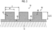
- Fig. 1 is a view illustrating a stripe coated film 64 when viewed from the above as an example of the surface roughness structure of a back coat layer 70
- Fig. 2 is a longitudinal cross-sectional view taken along line a-a of Fig. 1
- the stripe coated film 64 is formed by arranging belt-like thick film portions 62 on planar thin film portions 60 on the rear surface of a belt-like support 12. In this manner, a surface roughness structure in which the belt-like thin film portions 60 and the belt-like thick film portions 62 are alternately arranged in parallel with a longitudinal direction (the same as the traveling direction of the support in the production method) of the belt-like support 12 is formed.
- the stripe coated film 64 is formed on the entire rear surface of the belt-like support 12 such that the surface does not have uncoated portions.
- ear portions 12A which are both end portions of the belt-like support 12 may remain uncoated.
- the contact area ratio of the thick film portions 62 to the thin film portions 60 and the thick film portions 62 is preferably in a range of 5% to 90%, more preferably in a range of 30% to 80%, and particularly preferably in a range of 50% to 75% (hereinafter, referred to as a "thick film portion contact area ratio").
- a thick film portion contact area ratio is 5% or greater in the planographic printing plate precursor, printing stain is unlikely to occur.
- the thick film portion contact area ratio is 90% or less, an air release property at the time of lamination of planographic printing plate precursors becomes excellent, and adhesion between plates does not occur.
- the thick film portion contact area ratio is an area ratio specified using a prescale (manufactured by Fujifilm Corporation) which is a film capable of measuring the pressure and the pressure distribution.
- a prescale is placed by being interposed between a smooth plate and a prepared stripe coated film whose area is to be measured. Both entire surfaces are pressurized from the upper and lower sides at 0.59 MPa (6 kgf/cm 2 ) for 2 minutes, and the area ratio of sites where a coloration of 0.59 MPa or greater is seen with the prescale to the target area to be measured is defined as the contact area ratio.
- a difference Zt in thickness between the thick film portion 62 and the thin film portion 60 which are adjacent to each other is preferably in a range of 1 ⁇ m to 50 ⁇ m (hereinafter, referred to as a "thickness difference Zt").
- the thickness difference Zt is more preferably in a range of 1 ⁇ m to 20 ⁇ m and particularly preferably in a range of 2 ⁇ m to 10 ⁇ m.
- a thickness difference Zo indicates a thickness difference in a wet state immediately after the rear surface of the belt-like support 12 is coated with the coating solution forming the stripe coated film 64.
- a width W of the thick film portion 62 is preferably in a range of 0.5 mm to 50 mm (hereinafter, referred to as a "thick film portion width W").
- the width W of the thick film portion 62 in the planographic printing plate precursor is 0.5 mm or greater, plates are unlikely to be damaged because the plates are deviated from each other at the time of lamination. Further, in a case where the width W thereof is 50 mm or less, the air release property becomes excellent.
- a pitch ⁇ between the thick film portions 62 is preferably in a range of 0.5 mm to 50 mm (hereinafter, referred to as a distance ⁇ between thick film portions").
- a distance ⁇ between thick film portions In planographic printing plates, in a case where the pitch ⁇ between the thick film portions 62 is 0.5 mm or greater, the air release property at the time of lamination becomes excellent, and adhesion between plates does not occur. Further, in a case where the pitch ⁇ between the thick film portions 62 is 50 mm or less, printing stain does not occur.
- a ratio Z t / ⁇ of the thickness difference Zt between the thin film portion 60 and the thick film portion 62 which are adjacent to each other to the pitch ⁇ is preferably 0.10 or less. Further, a ratio Z t /W of the thickness difference Z t to the width W of the thick film portion 62 is preferably 0.10 or less.
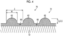
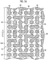
- Fig. 3 is a view illustrating a dot coated film 72 when viewed from the above as an example of the surface roughness structure of the back coat layer 70
- Fig. 4 is a longitudinal cross-sectional view taken along line b-b of Fig. 3
- the dot coated film 72 is a surface roughness structure in which dot-like thick film portions 62 are scattered on planar thin film portions 60 on the rear surface of the belt-like support 12.
- Figs. 3 and 4 illustrate the case in which the dot-like thick film portions 62 are regularly scattered, but the dot-like thick film portions 62 may be irregularly (randomly) scattered.
- the planar thin film portions 60 are formed on the entire rear surface of the belt-like support 12 such that the surface does not have uncoated portions, and the dot-like thick film portions 62 are scattered on the thin film portions 60.
- ear portions 12A which are both end portions of the belt-like support 12 may remain uncoated.
- Fig. 5 is a view illustrating a dashed line coated film when viewed from the above as an example of the surface roughness structure of the back coat layer 70
- Fig. 6 is a longitudinal cross-sectional view taken along line c-c of Fig. 5
- a dashed line coated film 74 is a surface roughness structure in which dashed line thick film portions 62 are formed on planar thin film portions 60 on the rear surface of the belt-like support 12.
- Figs. 5 and 6 illustrate the case in which the dashed line thick film portions 62 are regularly formed, but the dashed line thick film portions 62 may be irregularly (randomly) formed.
- the planar thin film portions 60 are formed on the entire rear surface of the belt-like support 12 such that the surface does not have uncoated portions, and the dashed line thick film portions 62 are formed on the thin film portions 60.
- ear portions 12A which are both end portions of the belt-like support 12 in the width direction may remain uncoated.
- a new surface roughness structure different from a structure of the related art is formed on the back coat layer 70 of the planographic printing plate precursor according to the embodiment of the present invention.
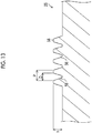
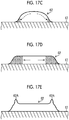
- Fig. 7 illustrates a case where the stripe coated film 64 or the dashed line coated film 74 is formed using the thin film portion 60 and the thick film portion 62, and horn-like protrusions 62A are likely to be formed on both end portions of the thick film portion 62 in the width direction (short width direction).
- Fig. 8 illustrates the dot coated film 72, and horn-like protrusions 62A are likely to be formed on the peripheral portion of the dot-like thick film portion 62.
- the formation of horn-like protrusions 62A may result in printing stain.
- the back coat layer 70 having an arithmetic average height Sa of 0.5 ⁇ m or greater using the surface roughness structure in which the thin film portions 60 and the thick film portions 62 are continuously formed and prevent formation of horn-like protrusions 62A.
- planographic printing plate precursor of the present invention which is capable of forming the back coat layer 70 having an arithmetic average height Sa of 0.5 ⁇ m or greater using the surface roughness structure in which the thin film portions 60 and the thick film portions 62 are continuously formed and capable of preventing formation of horn-like protrusions 62A will be described.
- the present invention can be applied to a case where the planographic printing plate precursor is produced using a sheet-like support (substrate) and a case where the planographic printing plate precursor is produced using a belt-like support, and the case of the belt-like support 12 will be described in the present embodiment.
- Fig. 9 is a view schematically illustrating the overall configuration of a producing device that produces a planographic printing plate precursor.
- a producing device 10 of the planographic printing plate precursor includes a coater 14 for a polymer layer that continuously coats the surface of the belt-like support 12 with a coating solution for a polymer layer; a dryer 16 for a polymer layer that dries the applied polymer layer in a wet state; support cooling means 25 for cooling the belt-like support 12 before the surface thereof is coated with the coating solution for a stripe coated film; a coater 18 for a stripe coated film that coats the rear surface of the belt-like support 12 with a coating solution for a stripe coated film; and a dryer 20 for a stripe coated film that dries the applied stripe coated film in a wet state.
- Examples of the belt-like support 12 according to the embodiment of the present invention includes paper, a polyester film, and an aluminum plate.
- an aluminum plate subjected to a roughening treatment and an anodizing treatment according to a known method is preferable.
- An aluminum plate has excellent dimensional stability, is relatively inexpensive, and can be provided with a surface having excellent hydrophilicity or strength by performing a surface treatment as necessary.
- a composite sheet obtained by bonding an aluminum sheet to a polyethylene terephthalate film is also preferable.
- the aluminum plate can be subjected to a treatment appropriately selected from an expansion treatment or a sealing treatment of micropores of an anodized film described in JP2001-253181A or JP2001-322365A or a surface hydrophilization treatment using alkali metal silicate described in US2714066A , US3181461A , US3280734A , and US3902734A or polyvinyl phosphonic acid described in US3276868A , US4153461A , and US4689272A as necessary.
- the rear surface of the belt-like support 12 which includes the back coat layer 70 and has not been subjected to a roughening treatment has an arithmetic average height Sa of 0.30 ⁇ m or less. This clarifies that the arithmetic average height Sa of the back coat layer does not go beyond 0.5 ⁇ m due to the surface roughness of the rear surface of the belt-like support 12, in the method of producing the planographic printing plate precursor according to the present embodiment.
- the surface of the belt-like support 12 onto which a roughening treatment or an undercoat layer has been applied as necessary is coated with a coating solution for a polymer layer by the coater 14 for a polymer layer.
- Each component constituting various polymer layers described above is dispersed or dissolved in a known volatile solvent to prepare a coating solution for a polymer layer, and the belt-like support 12 to be continuously transported is coated with this coating solution.
- a slide bead type coater illustrated in Fig. 9 can be used as the coater 14 for a polymer layer.
- a known coater such as a bar coater or an extrusion type coater can be used.
- the coating solution supplied to a pocket portion 14A of the coater main body flows through a slit 14B, is jetted to a slide surface 14C, flows through the slide surface 14C, and is applied to the belt-like support 12 through a bead (coating solution reservoir) from the tip of the slide surface.
- the reference numeral 32 is a pass roller that transports the belt-like support 12.
- the polymer layer in a wet state which is formed by coating the belt-like support 12 with the coating solution for a polymer layer is dried by the dryer 16 for a polymer layer.
- the dryer 16 for a polymer layer can be operated according to various drying systems such as a hot air system of blowing hot air to a polymer layer, a heater heating system of performing drying using a heater of infrared rays or the like, and a heating roll system of bringing a heating roll into contact with a belt-like support.
- a hot air system is particularly preferable.
- the polymer layer is dried in heated air, for example, at a temperature of 100°C or higher and a dew point of 5°C to 20°C.
- the temperature of the belt-like support 12 which is increased by dry heat of the dryer 16 for a polymer layer is cooled by the support cooling means 25.
- one cooling means may be used, but it is preferable that two cooling means of first cooling means 29 and second cooling means 31 are used from the viewpoints of the purpose and the cooling efficiency.
- the first cooling means 29 rapidly decreases the temperature of the belt-like support 12 until the temperature thereof becomes 30°C to 40°C for the purpose of preventing transfer of the polymer layer to transport pass rollers 32, 32, ... due to stickiness and preventing damage or distortion of the belt-like support 12.
- the second cooling means 31 decreases the temperature of the belt-like support to be in a range as the temperature range of the coating solution for a stripe coated film described below such that the viscosity of the coating solution for a stripe coated film to be applied to the rear surface of the belt-like support 12 in the subsequent step is not changed.
- the belt-like support is typically cooled to room temperature.
- the belt-like thick film portions 62 and the belt-like thin film portions 60 are continuously and alternately arranged in parallel with the traveling direction of the belt-like support 12 as illustrated in Fig. 1 , on the rear surface of the belt-like support 12 whose surface is provided with a polymer layer, and the stripe coated film 64 in which the difference in thickness between the thick film portion 62 and the thin film portion 60 which are adjacent to each other is in a range of 1 ⁇ m to 50 ⁇ m is formed as follows. In other words, a coated film is formed on the entire rear surface of the belt-like support 12 which does not have uncoated portions.
- the ear portions 12A which are both end portions of the belt-like support 12 may remain uncoated.
- a coating solution F for a stripe coated film can be prepared by dispersing or dissolving each component such as a resin component constituting the composition of the stripe coated film 64 in a known volatile solvent.
- the resin component and the solvent of the stripe coated film 64 a resin component and a solvent for forming a back coat layer of a planographic printing plate can be preferably used.
- the resin component contains an organic polymer as a base polymer constituting the back coat layer 70 according to the embodiment of the present invention.
- the organic polymer can be selected from the group consisting of a novolak resin such as a phenol formaldehyde resin, an m-cresol formaldehyde resin, a p-cresol formaldehyde resin, an m-/p-mixed cresol formaldehyde resin, or a phenol/cresol (any of m-, p-, and m-/p-mixed)-mixed formaldehyde resin, a resol resin, pyrogallol, an acetone resin, and an epoxy resin.
- a novolak resin such as a phenol formaldehyde resin, an m-cresol formaldehyde resin, a p-cresol formaldehyde resin, an m-/p-mixed cresol formaldehyde resin, or a phenol/cresol (any of m-, p-, and m-/p-mixed)-mixed formaldehyde resin, a
- a saturated copolymer polyester resin a phenoxy resin, a polyvinyl acetal resin, a vinylidene chloride copolymer resin, or the like can also be used.
- hydrophobic polymer compounds such as polybutene, polybutadiene, polyamide, an unsaturated copolymer polyester resin, polyurethane, polyurea, polyimide, polysiloxane, polycarbonate, an epoxy resin, chlorinated polyethylene, an aldehyde condensation resin of alkyl phenol, polyvinyl chloride, polyvinylidene chloride, polystyrene, an acrylic resin, and copolymer resins of these, hydroxy cellulose, polyvinyl alcohol, cellulose acetate, and carboxymethyl cellulose may be used.
- hydrophobic polymer compounds such as polybutene, polybutadiene, polyamide, an unsaturated copolymer polyester resin, polyurethane, polyurea, polyimide, polysiloxane, polycarbonate, an epoxy resin, chlorinated polyethylene, an aldehyde condensation resin of alkyl phenol, polyvinyl chloride, polyvinylidene chloride, polystyrene, an
- a novolak resin, a resol resin, a pyrogallol acetone resin, an epoxy resin, or a polystyrene resin is preferably used from the viewpoints of the heat resistance, the chemical resistance, and the cost.
- the content of the organic polymer contained in the total solid content of the back coat layer 70 is preferably in a range of 99.7% to 40% by mass, more preferably in a range of 99% to 60% by mass, and particularly preferably in a range of 98% to 80% by mass.
- the content of the crosslinking agent in the organic polymer layer which is to be used in combination is preferably in a range of 0.3% to 30% by mass and more preferably in a range of 1% to 20% by mass expressed in terms of solid contents.
- the back coat layer 70 contains at least one non-alkali-soluble resin. Further, it is preferable that the back coat layer 70 contains at least one non-photo curable resin having a weight-average molecular weight of 3000 or less.
- various fillers can be added within the range not impairing the effects of the present invention.
- the filler include calcium carbonate powder, silica powder, wood powder, and pulp.
- the content of the filler is preferably in a range of 1% to 50% by mass and more preferably in a range of 5% to 30% by mass expressed in terms of solid contents.
- these fillers need to be added under the condition in which the effects of the present invention are not impaired, the type or the amount of the filler to be added is adjusted in the case where the effects thereof are impaired.
- a plasticizer, a surfactant, and other additives can be added to the back coat layer 70 as necessary within the range not impairing the effects of the present invention.
- plasticizers examples include phthalic acid esters such as dimethyl phthalate, diethyl phthalate, dibutyl phthalate, diisobutyl phthalate, dioctyl phthalate, octyl capryl phthalate, dicyclohexyl phthalate, ditridecyl phthalate, butyl benzyl phthalate, diisodecyl phthalate, and diallyl phthalate; glycol esters such as dimethyl glycol phthalate, ethyl phthalyl ethyl glycolate, methyl phthalyl ethyl glycolate, butyl phthalyl butyl gylcolate, and triethylene glycol dicaprylic acid ester; phosphoric acid esters such as tricresyl phosphate and triphenyl phosphate; aliphatic dibasic acid esters such as diisobutyl adipate, dioctyl adipate,
- the amount of the plasticizer to be added to the back coat layer 70 varies depending on the type of the organic polymer used for the back coat layer 70, but it is preferable that the plasticizer is added in a range that the glass transition temperature does not become 60°C or lower.
- surfactant examples include anionic, cationic, non-ionic, and amphoteric surfactants.
- non-ionic surfactants such as polyoxyethylene alkyl ethers, polyoxyethylene alkyl phenyl ethers, polyoxyethylene polystyryl phenyl ethers, polyoxyethylene polyoxypropylene alkyl ethers, glycerin fatty acid partial esters, sorbitan fatty acid partial esters, pentaerythritol fatty acid partial esters, propylene glycol monofatty acid esters, sucrose fatty acid partial esters, polyoxyethylene sorbitan fatty acid fatty acid partial esters, polyoxyethylene sorbitol fatty acid partial esters, polyethylene glycol fatty acid esters, polyglycerin fatty acid partial esters, polyoxyethylenated castor oils, polyoxyethylene glycerin fatty acid partial esters, fatty acid diethanolamides, N,N-bis-2-hydroxyalkyl
- polyoxyethylene in the surfactants exemplified above can be replaced with polyoxyalkylene such as polyoxymethylene, polyoxypropylene, or polyoxybutylene, and examples of the surfactants also include these surfactants.
- a fluorine-based surfactant containing a perfluoroalkyl group in a molecule is more preferable as the surfactant.
- the fluorine-based surfactant include an anionic surfactant such as perfluoroalkyl carboxylate, perfluoroalkyl sulfonate, or perfluoroalkyl phosphoric acid ester; an amphoteric surfactant such as perfluoroalkyl betaine; a cationic surfactant such as perfluoroalkyl trimethyl ammonium salts; a non-ionic surfactant such as perfluoroalkylamine oxide, a perfluoroalkyl ethylene oxide adduct, a perfluoroalkyl group and a hydrophilic group-containing oligomer, a perfluoroalkyl group and a lipophilic group-containing oligomer, a perfluoroalkyl group, a hydrophilic group and a lipophilic group-containing
- the surfactants can be used alone or in combination of two or more kinds thereof, and the amount thereof to be added to the back coat layer 70 is preferably in a range of 0.001% to 10% by mass and more preferably in a range of 0.01% to 5% by mass.
- a volatile component is preferable, and examples thereof include methyl ethyl ketone, ethylene glycol monomethyl ether, 1-methoxy-2-propanol, 2-methoxyethyl acetate, 1-methoxy-2-propyl acetate, and ⁇ -butyllactone, but the present invention is not limited to these. These solvents can be used alone or in a mixture.
- the concentration of solid contents in the coating solution is preferably in a range of 1% to 50% by mass.
- the coating solution F for a stripe coated film flows through a pipe 36 by a pump 34 and is sent to the coater 18 for a stripe coated film, and the temperature thereof is adjusted to a set coating solution temperature by coating solution cooling means 22 provided in the middle of the pipe 36.
- the rear surface of the belt-like support 12 is coated with the coating solution F for a stripe coated film by the coater 18 for a stripe coated film such that the thickness difference between the thick film portion 62 and the thin film portion 60 which are adjacent to each other is in a range of 1 ⁇ m to 50 ⁇ m to form the stripe coated film 64 in a wet state having the surface roughness structure illustrated in Fig. 1 .
- the rear surface is coated with the coating solution such that the thickness difference between the thick film portion 62 and the thin film portion 60 which are adjacent to each other is in a range of 1 ⁇ m to 50 ⁇ m, in the stripe coated film 64 in a wet state before being dried.
- the surface is coated with the coating solution under coating conditions in which the viscosity of the coating solution F is in a range of 0.3 mPa ⁇ s to 100 mPa ⁇ s (hereinafter, referred to as a "viscosity condition”), the surface tension of the coating solution F is in a range of 20 mN/m to 40 mN/m (hereinafter, referred to as a "surface tension condition”), and the contact angle between the coating solution and the belt-like support 12 is in a range of 10° to 90° (hereinafter, referred to as a "contact angle condition").
- the three coating conditions of the "viscosity condition", the "surface tension condition”, and the “contact angle condition” are prerequisites specified to achieve two purposes for “forming a stripe coated film” and “preventing formation of horn-like protrusions".
- the coating of the surface under the above-described three coating conditions are prerequisites for the method of producing the planographic printing plate precursor of the present invention.
- the viscosity of the coating solution F is greater than 100 mPa ⁇ s, the problem of generation of horn-like protrusions 62A on the thick film portions 62 does not occur. Further, it is practically difficult to prepare a coating solution having a viscosity of less than 0.3 mPa ⁇ s. Therefore, the coating of the surface with a coating solution having a viscosity of 0.3 mPa ⁇ s to 100 mPa ⁇ s is a prerequisite for achieving the purpose of "preventing formation of horn-like protrusions".
- the contact angle between the coating solution F and the belt-like support 12 is less than 10°, since the wettability becomes excellent, the stripe coated film 64 cannot be formed. Further, in a case where the contact angle therebetween is greater than 90°, the horn-like protrusions 62A are generated on the thick film portions 62 under any coating conditions or drying conditions. Therefore, the coating performed under the condition in which the contact angle between the coating solution F and the belt-like support 12 is in a range of 10° to 90° is a prerequisite for achieving two purposes of "formation of a stripe coated film" and "preventing formation of horn-like protrusions".
- the stripe coated film 64 may not be formed. Further, in a case where the surface tension is greater than 40 mN/m and the viscosity and the contact angle are respectively in the above-described range, generation of the horn-like protrusions 62A on the thick film portions 62 is not constant because the horn-like protrusions 62A are generated in some cases, but are not generated in other cases under any coating conditions and drying conditions.
- the coating of the surface with the coating solution F having a surface tension of 20 mN/m to 40 mN/m is a prerequisite for achieving two purposes of "formation of a stripe coated film” and "preventing formation of horn-like protrusions".
- the method of forming the stripe coated film 64 on the belt-like support 12 is not limited to the bar coater 24, and the coated film can be applied and then formed using any system from among an ink jet printing system, a gravure printing system, a screen printing system, a spray coating system, and a slot die coating system.
- the bar coater 24 is a device that coats the belt-like support 12, which travels by being guided by an upstream side guide roller 26 and a downstream side guide roller 27 the coating solution F, using a coating head 30 including a coating bar 28.
- the upstream side guide roller 26 and the downstream side guide roller 27 are disposed such that the belt-like support 12 travels close to the coating bar 28.
- the upstream side guide roller 26 and the downstream side guide roller 27 are supported in a state parallel to the coating bar 28.
- the coating bar 28 is rotationally driven as indicated by the arrow of Fig. 10 . It is preferable that the rotation direction of the coating bar 28 is set to be a forward rotation direction with respect to the transport direction of the belt-like support 12 at a circumferential speed which is the same as the speed of the belt-like support 12. Further, coating performed by the coating bar driving in a direction opposite to the rotation direction illustrated in Fig. 10 , that is, the reverse direction with respect to the transport direction and coating performed without rotational driving can be employed depending on the coating conditions.
- the coating head 30 mainly includes the coating bar 28, a backup member 38, and coater blocks 40 and 42, and the coating bar 28 is rotatably supported by the backup member 38.
- Manifolds 44 and 46 and slots 48 and 50 are formed between the backup member 38 and each of the coater blocks 40 and 42, and the coating solution F for a stripe coated film is supplied to each of the manifolds 44 and 46.
- the coating solution F supplied to each of the manifolds 44 and 46 is uniformly extruded in the width direction of the belt-like support 12 through the narrow slots 48 and 50.
- an upstream side coating bead 52 is formed on the upstream side
- a downstream side coating bead 54 is formed on the downstream side of the feeding direction of the belt-like support 12 with respect to the coating bar 28.
- the rear surface of the traveling belt-like support 12 is coated with the coating solution F through these coating beads 52 and 54.
- Fig. 11 is an overall view illustrating the coating bar 28.
- Fig. 12 is a partial cross-sectional view illustrating the coating bar 28.
- Fig. 13 is a partially enlarged cross-sectional view illustrating the coating bar 28 of Fig. 12 by enlarging the vicinity of the surface of the bar.
- grooved portions A where grooves are formed in the circumferential direction of the bar and groove-free portions B where grooves are not formed are alternately arranged on the surface of the columnar coating bar 28 in the axial core direction (width direction of the belt-like support 12) of the coating bar 28. Further, grooves may or may not be formed in both end portions C of the coating bar 28, but a case where grooves are not formed will be described in the present embodiment.
- a groove in the grooved portion A is formed of a depression 56 and a projection 58, and the groove is formed in a trapezoidal shape. Further, the shape of the groove is not limited to the trapezoidal shape and may be a sine wave shape. It is preferable that a diameter D 1 of the groove-free portion B is set not to be smaller than a bar diameter (diameter of the coating bar) D 3 in the depression 56 of the grooved portion A.
- the groove-free portion B is unlikely to be coated with the coating solution F at the time of coating the belt-like support 12 with the coating solution F for a stripe coated film using the coating bar 28.
- the diameter D 1 of the groove-free portion B is set to be larger than the bar diameter D 3 of the depression 56 in the grooved portion A and to be smaller than an average value D 2 of bar diameters in depressions 56 and projections 58.
- the pitch length between depressions 56 or projections 58 adjacent to each other is set as P
- the depth of the depression 56 is set as h
- the opening width of the depression 56 is set as D
- P satisfies 0.25 mm or greater
- h/D is in a range of 0.01 to 0.55
- D/P is 0.49 or less.
- the upper limit value of the pitch length P is determined depending on the length of the thin film portion 60 or the thick film portion 62 of the stripe coated film 64 intended to be formed, but the upper limit value is preferably 10 mm or less.
- the stripe coated film 64 with less unevenness (coating unevenness) can be formed on the coated film surface.
- the stripe coated film 64 illustrated in Fig. 1 can be coated with the coating solution.
- two kinds of grooved portions A with different groove depths formed of grooved portions A1 with shallow grooves and grooved portions A2 with deep grooves can be employed.
- a depth h 1 of the depression 56 in the grooved portion A1 with shallow grooves is smaller than a depth h 2 of the depression 56 in the grooved portion A2 with deep grooves.
- the projection 58 of the grooved portion A1 with shallow grooves is flush with the projection 58 of the grooved portion A2 with deep grooves.
- the depths of two kinds of grooves in the grooved portion A1 with shallow grooves and the grooved portion A2 with deep grooves can be set according to the film thicknesses of the thin film portion 60 and the thick film portion 62 to be formed.
- the method of forming grooves in the surface of the coating bar 28 is not particularly limited, and various processing methods can be used. Preferred examples thereof include cutting processing, rolling processing, and laser processing.
- the stripe coated film is coated with the coating solution F for a stripe coated film using the coating bar 28 having a diameter D 0 (see Fig. 11 ) of 6 mm to 50 mm and the relationship between the rotation speed r of the coating bar 28 and the viscosity ⁇ of the above-described coating solution F satisfies Formula (3).
- the diameter D 0 of the coating bar 28 is more preferably in a range of 6 mm to 20 mm. r ⁇ 65714 ⁇ ⁇ ⁇ 1.122
- Fig. 15 shows test results obtained by investigating the influence of the relationship, between the rotation speed r of the coating bar 28 and the viscosity ⁇ of the above-described coating solution F, on the mixture of foams.
- the curve of Fig. 15 is a foam mixture limit curve E showing that foams are not mixed into the coating solution F of the stripe coated film and can be represented by Formula (4).
- r 65714 ⁇ ⁇ 1.122
- a region on the lower side of the foam mixture limit curve E is a region (G region) where foams are not mixed, and a region on the upper side of the foam mixture limit curve is a region (H region) where foams are mixed.
- the viscosity ⁇ horizontal axis
- the rotation speed r vertical axis
- foams are mixed even in a case where the rotation speed r of the coating bar 28 is set to be small.
- the stripe coated film 64 in a wet state which has been formed on the rear surface of the belt-like support 12 is dried using the dryer 20 for a stripe coated film to form the stripe coated film 64 (hereinafter, also referred to as a "dry film”) in a dry state.
- the dryer 20 for a stripe coated film can be operated according to various drying systems such as a hot air system of blowing hot air to the stripe coated film 64 in a wet state, a heater heating system of performing drying using a heater of infrared rays or the like, a heating roll system of bringing a heating roll into contact with the belt-like support 12, and a condensation drying system of performing drying using a condensation plate.
- a hot air system is particularly preferable.
- Fig. 16 illustrates an example of the dryer 20 for a stripe coated film having a hot air system, and the casing of the dryer is not illustrated.
- a rectangular nozzle 66 is provided in the vicinity of the film surface of the stripe coated film 64 applied to the rear surface of the belt-like support 12.
- a pipe 68 connected to a dry wind supply device (not illustrated) that blows hot dry wind is connected to the nozzle 66, and dry wind is blown out from a slit-like outlet 66A in parallel with the film surface of the stripe coated film 64 and in the transport direction or in the direction opposite to the transport direction of the belt-like support 12.
- the coated film surface can be dried in a short time without generating unevenness (dry unevenness) thereon.
- the film surface is dried in heated air, for example, at a temperature of 100°C or higher and a dew point of 5°C to 20°C.
- a parallel wind component of the dry wind blown out from the nozzle 66 to the coated film surface is less than or equal to a relative wind speed of 30 m/s.
- the parallel wind component of the dry wind to the coated film surface is greater than a relative wind speed of 30 m/s, unevenness (dry unevenness) easily occurs on the coated film surface of the stripe coated film 64.
- the relative wind speed is a wind speed obtained based on the relative relationship with the transport speed of the belt-like support 12.
- a drying point (t) at the time of drying the stripe coated film 64 in a wet state to form the stripe coated film 64 in a dry state satisfies Formulae 1 and 2.
- the drying point indicates the time point at which the stripe coated film 64 applied to the belt-like support 12 enters a dry state in which the surface gloss of the stripe coated film 64 is not changed any more, and the drying time from the start of drying to the drying point can be known.
- the drying point is a critical point of transition from a constant rate drying period to a falling rate drying period and also indicates the time point at which the viscosity of the stripe coated film 64 becomes 1 Pa ⁇ s or greater and the shapes of the thin film portion 60 and the thick film portion 62 constituting the stripe coated film 64 are fixed.
- Formula 1 is a formula (hereinafter, referred to as a "condition for forming a stripe coated film") for obtaining the stripe coated film 64 which is intended to be formed and has a difference in film thickness in a dry state using a leveling formula of Orchard related to the leveling of a coating solution, by setting the time point to the drying point (t) before the thick film portions 62 and the thin film portions 60 are leveled to be flat in a case where the stripe coated film 64 in a wet state is applied and formed on the belt-like support 12.
- a condition for forming a stripe coated film for obtaining the stripe coated film 64 which is intended to be formed and has a difference in film thickness in a dry state using a leveling formula of Orchard related to the leveling of a coating solution, by setting the time point to the drying point (t) before the thick film portions 62 and the thin film portions 60 are leveled to be flat in a case where the stripe coated film 64 in a wet state is applied and formed
- the parameters (X, ⁇ , Zo) related to the shape of the stripe coated film 64 in a wet state, the physical properties ( ⁇ , ⁇ ) of the coating solution, and the difference (Zt) in film thickness of the stripe coated film 64 which is intended to be formed in a dry state are substituted on the right side of Formula 1. In this manner, the leveling between the thick film portions 62 and the thin film portions 60 progresses, and the drying time until the difference in thickness of a film intended to be formed is eliminated can be acquired.
- the stripe coated film 64 with the difference in film thickness which is intended to be formed can be obtained from the inequality of Formula 1.
- 0.033 which is the constant used in Formula 1 is fitted from a test so as to satisfy the conditions for parameters and thus is different from the constant of the leveling formula of Orchard.
- Pe is a numerical value obtained by dividing a drying speed by a diffusion coefficient of a coating solution, and 1.5 ⁇ 10 -6 which is the constant of the Peclet number is based on the test results.
- Formula 2 defines the condition in which the horn-like protrusion 62A is formed on both ends of the thick film portion 62 in the width direction and shows the relationship of three formulae, which are the left side formula, the central formula, and the right side formula, using an inequality (hereinafter, referred to as a "condition for preventing formation of horn-like protrusions").
- Fig. 17A illustrates the thick film portion 62 of the stripe coated film 64 in a wet state immediately after being applied on the belt-like support 12.
- the thick film portion 62 immediately after being applied has a rectangular shape since the leveling has not occurred yet.
- the thick film portion 62 in this rectangular shape has a mountain shape whose skirt portions are expanded as illustrated in Fig. 17B due to the progression of leveling with time.
- the concentration of the skirt portions at both ends of the thick film portion 62 in the width direction becomes higher than the concentration of the central portion thereof due to the surface tension gradient occurring inside the thick film portion 62 as illustrated in Fig. 17C .
- the portion with a high concentration is indicated by the net shape. In this manner, as illustrated in Fig.
- the relationship between the left side formula and the right side formula (left side formula ⁇ right side formula) in Formula 2 shows the condition in which the surface tension gradient is generated in the thick film portion 62 of the stripe coated film 64 and the driving force for collecting the liquid inside the thick film portion 62 in the end portions is generated.
- the relationship between the left side formula and the central formula shows that horn-like protrusions are not generated under conditions in which (a) the resistance at the time of movement of the liquid is large, (b) the driving force itself is weak, and (c) the time for movement is short even in a case where the driving force (right side formula) for collecting the liquid inside the thick film portion 62 in the end portions is activated.
- the horn-like protrusions 62A are not generated on both end portions of the belt-like thick film portion 62 in the width direction in a case where the stripe coated film 64 is dried up to the drying point (t) by at least one action of (a) to (c) described above before the horn-like protrusions 62A are generated due to the driving force in the right side formula.
- the horn-like protrusions 62A are not generated in a case where the stripe coated film is dried up to the drying point in a short time before the horn-like protrusions 62A are generated due to the driving force.
- the coater 18 for a stripe coated film and the dryer 20 for a stripe coated film illustrated in Fig. 9 are disposed as close to each other as possible and the coated film is dried at a high speed.
- the stripe coated film 64 can be dried so that the horn-like protrusions 62A are not formed on both ends of the belt-like thick film portion 62 in the width direction.
- the time for drying the stripe coated film 64 needs to satisfy Formulae 1 and 2 in consideration of the productivity and is preferably 20 seconds or shorter and more preferably 10 seconds or shorter.
- the back coat layer 70 which has a surface roughness structure of the stripe coated film 64 in which the belt-like thin film portions 60 and the belt-like thick film portions 62 are alternately and continuously arranged on the belt-like support 12 and has an arithmetic average height Sa of 0.5 ⁇ m or greater in which horn-like protrusions 62A are not formed on both ends of the thick film portion 62 in the width direction can be formed in a case where the "condition for forming a stripe coated film” of Formula 1 and the "condition for preventing formation of horn-like protrusions” of Formula 2 are satisfied in the drying step.
- planographic printing plate precursor including the belt-like support 12 and a polymer layer on the surface of the belt-like support
- the film will be formed in the following manner in a case of forming the back coat layer 70 having a surface roughness structure of the dot coated film 72 in which the thin film portions 60 and the thick film portions 62 are continuously formed on the rear surface of the belt-like support 12.
- a first coating step of solid-coating the entire rear surface of the belt-like support 12 with the coating solution F to form flat thin film portions 60 is performed.
- the ear portions 12A of the belt-like support 12 may remain uncoated.
- various coating devices having a slot coating system, an extrusion coating system, a slide bead coating system, a roll coating system, and the like can be used.
- the dot coated film 72 in a wet state is formed by performing the coating such that a difference in thickness between the thin film portion 60 and the thick film portion 62 is set to be in a range of 1 ⁇ m to 50 ⁇ m.
- coating devices having an ink jet printing system and a screen printing system can be suitably used.
- a coating device having a screen printing system is particularly preferable.
- the coating conditions for forming the dot coated film 72 are the same as the "viscosity condition”, the “surface tension condition”, and the “contact angle condition” which are the conditions for forming the stripe coated film 64.
- drying conditions for drying the dot coated film 72 are the same as the conditions for satisfying Formula 1, Formula 2, and the relative wind speed of the dry wind which are the conditions for drying the stripe coated film 64.
- planographic printing plate precursor including the belt-like support 12 and a polymer layer on the surface of the belt-like support
- the film will be formed in the following manner in a case of forming the back coat layer 70 having a surface roughness structure of the dashed line coated film 74 in which the thin film portions 60 and the thick film portions 62 are continuously formed on the rear surface of the belt-like support 12.
- a first coating step of solid-coating the entire rear surface of the belt-like support 12 with the coating solution F to form flat thin film portions 60 is performed.
- the ear portions 12A of the belt-like support 12 may remain uncoated.
- various coating devices having a slot coating system, an extrusion coating system, a slide bead coating system, a roll coating system, and the like can be used.
- the dashed line coated film 74 in a wet state is formed by performing the coating such that a difference in thickness between the thin film portion 60 and the thick film portion 62 is set to be in a range of 1 ⁇ m to 50 ⁇ m.
- coating devices having an ink jet printing system and a screen printing system, similar to the dot coated film 72, can be suitably used.
- a coating device having a screen printing system is particularly preferable.
- the coating conditions for forming the dashed line coated film 74 are the same as the "viscosity condition”, the “surface tension condition”, and the “contact angle condition” which are the conditions for forming the stripe coated film 64.
- drying conditions for drying the dashed line coated film 74 are the same as the conditions for satisfying Formula 1, Formula 2, and the relative wind speed of the dry wind which are the conditions for drying the stripe coated film 64.
- planographic printing plate precursor including the belt-like support 12 and a polymer layer on the surface of the belt-like support
- a laminate according to the embodiment of the present invention is formed by cutting the belt-like planographic printing plate precursor produced in the above-described manner into a predetermined size and laminating a plurality of sheets (for example, approximately 100 sheets).
- the laminate according to the embodiment of the present invention is formed by laminating a plurality of planographic printing plate precursors respectively including a polymer layer on the surface of the support, having a surface roughness structure in which the belt-like thin film portions 60 and the belt-like thick film portions 62 are continuously and alternately formed on a rear surface of the support, and including the back coat layer 70 having an arithmetic average height Sa of 0.5 ⁇ m or greater.
- the laminate is packaged in this state and delivered to users.
- planographic printing plate precursors according to the embodiment of the present invention to be laminated respectively satisfy two constituent elements, which are the surface roughness structure (constituent element A) in which the thin film portions 60 and the thick film portions 62 are continuously formed on a rear surface of the belt-like support 12 and the back coat layer having an arithmetic average height Sa of 0.5 ⁇ m or greater (constituent element B) due to the surface roughness structure.
- the surface roughness structure in which the thin film portions 60 and the thick film portions 62 are continuously formed on a rear surface of the belt-like support 12
- the back coat layer having an arithmetic average height Sa of 0.5 ⁇ m or greater due to the surface roughness structure.
- planographic printing plate precursors according to the embodiment of the present invention are laminated to form the laminate, all purposes of 1) preventing scraping and peeling between planographic printing plate precursors, 2) preventing adhesion between planographic printing plate precursors, 3) imparting a plate-separating property for preventing multiple-plate feeding in a plate-making step of taking out planographic printing plate precursors from the laminate one by one, and 4) preventing scratches on a surface of a planographic printing plate precursor on a recording layer side, which are required for elimination of interleaving paper, can be satisfied. This will be described in detail in the fourth example in the section of examples.
- planographic printing plate precursor produced by the planographic printing plate precursor according to the embodiment of the present invention.
- the above-described method of producing the planographic printing plate precursor according to the embodiment of the present invention is not limited to the production of the planographic printing plate precursor and can be applied in a case of producing a coated film structure which includes a functional layer on the surface of a support and a back coat layer on the rear surface of the support.
- the coated film structure indicates a structure obtained by combining a support and a coated film formed on the support.
- a confirmation test for confirming basic confirmation items of the following a) to e) in the method of producing the planographic printing plate precursor according to the present invention was performed by actually producing a planographic printing plate precursor including a back coat layer of a stripe coated film.
- a planographic printing plate precursor was produced by coating the rear surface of the belt-like support 12, having a polymer layer for an untreated plate on the surface thereof, with a coating solution for a stripe coated film under the following conditions and drying the surface.
- the polymer layer for an untreated plate was formed as a three-layer structure of an undercoat layer, an image recording layer, and a protective layer in the following manner.
- the surface of the belt-like support 12 was coated with an undercoat layer coating solution having the following composition such that the drying coating amount was set to 20 mg/m 2 , thereby forming an undercoat layer.
- Compound (UC-1) for undercoat layer (Chemical Formula 1 shown below) 0.18 g • Hydroxyethyl imino diacetic acid 0.05 g • Surfactant (EMALEX 710, manufactured by Nihon Emulsion Co., Ltd.) 0.03 g • Water 28.0 g
- the undercoat layer was bar-coated with an image recording layer coating solution with the following composition and dried in an oven at 100° for 60 seconds, thereby forming an image recording layer having a drying coating amount of 1.0 g/m 2 .
- the image recording layer coating solution was obtained by mixing a photosensitive solution and a microgel solution described below immediately before the coating and then stirring the solution.
- Binder polymer (Chemical Formula 2 shown below) 0.240 g (weight-average molecular weight Mw: 55,000 and n (number of EO units): 2) • Infrared absorbing agent (Chemical Formula 3 shown below) 0.020 g • Borate compound (Sodium tetraphenyl borate) 0.010 g • Polymerization initiator (Chemical Formula 3 shown below) 0.162 g • Polymerizable compound 0.192 g
- Tris(acryloyloxyethyl) isocyanurate (NK ESTER A-9300, manufactured by Shin-Nakamura Chemical Co., Ltd.) • Anionic surfactant (Chemical Formula 3 shown below) 0.050 g • Fluorine-based surfactant (Chemical Formula 3 shown below) 0.008 g • 2-Butanone 1.091 g • 1-Methoxy-2-propanol 8.609 g
- a 4 mass% aqueous solution of polyvinyl alcohol (PVA-205, manufactured by KURARAY CO., LTD.) was prepared.
- the oil phase components and the water phase components were mixed with each other and emulsified at 12,000 rpm for 10 minutes using a homogenizer.
- 25 g of distilled water was added to the obtained emulsion, and the resultant was stirred at room temperature for 30 minutes and stirred at 50°C for 3 hours.
- the microgel solution obtained in this manner was diluted with distilled water such that the concentration of solid contents was set to 15% by mass, thereby preparing a microgel.
- the average particle diameter of the microgel measured by a light scattering method was 0.2 ⁇ m.
- the image recording layer was bar-coated with a protective layer coating solution with the following composition and dried in an oven at 120° for 60 seconds to form a protective layer having a drying coating amount of 0.15 g/m 2 , thereby preparing a planographic printing plate precursor.
- the back coat layer 70 was formed as follows.
- the coating solutions having the viscosity of 5 levels of 0.5 mPa ⁇ s, 1 mPa ⁇ s, 6 mPa ⁇ s, 30 mPa ⁇ s, and 80 mPa ⁇ s are prepared. Further, the surface tension of the coating solution F was adjusted to 4 levels of 25 mN/m, 27 mN/m, 30 mN/m, and 35 mN/m.
- the belt-like support 12 an aluminum plate having a thickness of 0.30 mm and a width of 1030 mm in conformity with JIS A 1050 (Japan Industrial Standards) was used. This belt-like support 12 was used at 2 levels of contact angles of 30° and 90° with respect to the coating solution F.
- the belt-like support 12 was coated while being continuously transported at a transport speed of 80 m/min using the bar coater 24 illustrated in Fig. 10 .
- the coating bar 28 having grooved portions A and groove-free portions B described in Figs. 11 to 13 were alternately arranged in the axial core direction of the coating bar 28 and having a diameter of 10 mm was used.
- the coating was performed by assigning the numerical values within the range of the condition for the viscosity ( ⁇ ) (0.3 mPa ⁇ s to 100 mPa ⁇ s), the range of the condition for the surface tension ( ⁇ ) (20 mN/m to 40 mN/m), and the range of the condition for the contact angle (10° to 90°), which are the prerequisites for achieving the purposes described above.
- the difference (Z 0 ) in initial film thickness was in three levels of 10 ⁇ m, 20 ⁇ m, and 40 ⁇ m.
- the rotation speed of the coating bar 28 was adjusted to 3 levels of 300 rpm, 1270 rpm, and 1500 rpm. Further, investigation was performed by assigning the numerical values within the ranges of P of 0.25 mm or greater, D/P of 0.49 or less, and h/D of 0.01 to 0.55 which are preferable conditions for grooves of the coating bar 28.
- the stripe coated film was dried at a drying temperature of 125°C using the dryer 20 of Fig. 16 which was provided with the rectangular nozzle 66 close to the film surface of the stripe coated film 64 to be continuously transported in a casing.
- the drying was performed by changing the relative wind speed of the parallel wind component of dry wind to the coated film surface in 9 levels of 0.1 m/s, 0.2 m/s, 3 m/s, 4 m/s, 5 m/s, 10 m/s, 20 m/s, 30 m/s, and 35 m/s.
- the numerical values of the upper limit values and the lower limit values are not particularly concerned at the time of assigning the numerical values of the parameters.
- a case where Formula 1 was satisfied was evaluated as A and a case where Formula 1 was not satisfied was evaluated as B in the table of Fig. 18A . Further, a case where Formula 2 was satisfied was evaluated as A and a case where Formula 2 was not satisfied was evaluated as B.
- the bar coater 24 having the coating bar 28 formed of the grooved portion A and the groove-free portion B described in Figs. 11 to 13 was used as the coater 18 for a stripe coated film that applies the stripe coated film. Accordingly, the influence on P of 0.25 mm or greater, D/P of 0.49 or less, and h/D or 0.01 to 0.55 that define the groove shape of the coating bar 28 was investigated. Further, the relationship between the rotation speed of the coating bar 28 and the mixture of foams into the coating solution F was investigated.
- test results 1 were obtained by performing evaluation of whether the stripe coated film 64 was formed and formation of the horn-like protrusions 62A was able to be prevented.
- a case where the stripe coated film 64 was formed and the horn-like protrusions 62A were not formed was evaluated as A. Further, a case where the stripe coated film 64 was not formed or the horn-like protrusions 62A were present was evaluated as B.
- the stripe coated film 64 was formed in a case where the difference Zt in dry film thickness between the thick film portion 62 and the thin film portion 60 adjacent to each other was measured using a contact type film thickness meter and the value was 1 ⁇ m or greater.
- the horn-like protrusions 62A were present in a case where the profile of the stripe coated film was measured using an electron microscope and the film thickness of the thick film portion 62 in an end portion was greater than the film thickness thereof in the central portion by 0.5 ⁇ m or greater.
- the "mixture of foams" was evaluated by visually observing the produced planographic printing plate precursors. In a case where foams were not mixed was evaluated as A, a case where mixture of foams was found in a portion of the thick film portion 62 was evaluated as B, and a case where mixture of foams was found in the entire surface was evaluated as C.
- the "unevenness of the stripe coated film" was evaluated by visually observing the produced planographic printing plate precursors. In a case where a color difference was not almost found was evaluated as A, a case where a color difference was slightly found was evaluated as B, and a color difference was clearly found was evaluated as C.
- Examples 1 to 22 satisfy all five conditions of the "viscosity condition", the "surface tension condition”, the “contact angle condition”, the “condition for forming a stripe coated film” of Formula 1, and the “condition for preventing formation of horn-like protrusions” of Formula 2.
- Comparative Example 1 to 8 did not satisfy at least one of the "condition for forming a stripe coated film" of Formula 1 and the "condition for preventing formation of horn-like protrusions" of Formula 2 from among the above-described five conditions.
- Examples 1 to 22 were evaluated as A since the stripe coated film 64 was able to be formed and horn-like protrusions were not formed on both ends of the thick film portion in the width direction, in all examples.
- Comparative Examples 1 to 8 Comparative Examples 1 and 7 were evaluated as B since the stripe coated film was not able to be formed. In other words, in Comparative Examples 1 and 7, a difference in film thickness between the thick film portion 62 and the thin film portion 60 was eliminated due to the leveling of the coated film in the drying step so that the coated film became flat.
- Comparative Examples 2 to 6 and 8 were evaluated as B since the stripe coated film 64 was formed, but the horn-like protrusions 62A were formed on both ends of the thick film portion 62 in the width direction.
- Fig. 19 is a schematic graph schematically showing the results obtained by measuring Comparative Example 2 in which the horn-like protrusions 62A were generated on both ends of the thick film portion 62 in the width direction using a contact type film thickness meter.
- Fig. 20 is a schematic graph schematically showing the results obtained by measuring Comparative Example 5 in which the horn-like protrusions 62A were generated on both ends of the thick film portion 62 in the width direction using a contact type film thickness meter.
- the longitudinal magnification was 1000 times and the lateral magnification was 10 times.
- the horn-like protrusions 62A are formed on both ends of all thick film portions 62 in the width direction. Further, in Fig. 20 , horn-like protrusions 62A are formed on both ends of the thick film portions 62 in the right half of the drawing in the width direction.
- Fig. 21 is a schematic graph schematically showing the results obtained by measuring Example 1 in which the horn-like protrusions 62A were not generated on both ends of the thick film portion 62 in the width direction using a contact type film thickness meter.
- Fig. 22 is a schematic graph schematically showing the results obtained by measuring Example 2 in which the horn-like protrusions 62A were not generated on both ends of the thick film portion 62 in the width direction using a contact type film thickness meter.
- the longitudinal magnification was 5000 times and the lateral magnification was 30 times.
- the longitudinal magnification was 2000 times and the lateral magnification was 10 times.
- the horn-like protrusions 62A were not generated on both ends of the thick film portion 62 in the width direction.
- test results 2 were obtained by testing the shape and the rotation speed of the coating bar 28, and the relative wind speed of the parallel wind component of dry wind blown to the coated film surface at the time of drying.
- Example 2 In consideration of the examples and the comparative examples in which P is 0.25 mm or greater, D/P is 0.49 or less, and h/D is 0.01 to 0.55 that define the shape of the groove in the coating bar 28 based on the table of Fig. 18A , Examples 2, 9, 11, 13, 17, 18, and Comparative Example 2 were evaluated as B since unevenness occurred in some cases. Particularly, in Example 17 in which the parallel wind component of dry wind blown to the coated film surface had a relative wind speed of 35 m/s, unevenness (dry unevenness) was observed from the stripe coated film 64. In Example 13, weak scratches were observed.
- the examples and the comparative examples in which the numerical values of the wind speed were set to be the same as each other the examples satisfy Formula 1 and Formula 2, but the comparative examples do not satisfy Formula 1 or Formula 2. Therefore, it is considered that the dry unevenness was affected in a case where the relative wind speed was greater than 35 m/s, but not only the dry unevenness but also the formation of the stripe coated film 64 and the prevention of generation of the horn-like protrusions 62A were not particularly affected in a region where the relative wind speed was less than 35 m/s.
- Example 17 in which the viscosity of the coating solution F was 30 mPa ⁇ s and the rotation speed was 1500 rpm and Example 18 in which the viscosity of the coating solution F was 30 mPa ⁇ s and the rotation speed was 1270 rpm were evaluated as B since mixture of foams was found. This evaluation coincides with the foam mixture limit curve in Fig. 9 .
- any test in the test results 2 did not have problems of formation of the stripe coated film 64 and prevention of formation of horn-like protrusions which were the main effects.
- a first laminate was formed by laminating 20 sheets of produced planographic printing plates without interposing interleaving paper therebetween. Further, a second laminate formed by allowing the surface of a polymer layer to face upward was set in advance in a cassette used for setting a laminate. Further, the first laminate was stacked on the second laminate which had been set in the cassette in advance by being deviated from an edge by 5 cm, pushed in the horizontal direction, and pushed into the cassette while rubbing the surface of the uppermost planographic printing plate on the polymer layer side of the second laminate.
- planographic printing plate whose surface on the polymer layer side was rubbed was visually observed whether the plate was damaged. A case where the plate was not damaged was evaluated as A and a case where the plate was damaged was evaluated as B.
- Example 23 in the table of Fig. 23 was the same as Example 1 in the table of Fig. 18A .
- the stripe coated film 64 of the example in Fig. 3 was formed such that the belt-like thick film portions 62 and the belt-like thin film portions 60 are continuously arranged on the rear surface of the belt-like support 12 so that the entire surface was coated.
- Comparative Example 9 assuming WO2014/202519A1 of the related art, stripe-like discontinuous partial coating was performed so that the rear surface of the belt-like support 12 had uncoated portions.
- Comparative Example 10 assuming WO2014/202519A1 of the related art, dot-like discontinuous partial coating was performed so that the rear surface of the belt-like support 12 had uncoated portions.
- Example 23 was evaluated as A since the plate was not damaged and all comparative examples were evaluated as B. Based on this, it was proved that the entire rear surface of the belt-like support 12 is required to be coated in order to prevent damage to the planographic printing plate and this means that the belt-like thick film portions 62 and the belt-like thin film portions 60 need to be continuously arranged on the rear surface of the belt-like support 12.
- the "adsorptivity of the plate” was evaluated by adjusting the humidity of 3 sheets of produced planographic printing plate precursors in an environment of a temperature of 25°C at a relative humidity of 75% for 2 hours, and sequentially stacking the precursors in a state in which the 3 sheets of planographic printing plate precursors were directed to the same direction and interleaving paper was not interposed between precursors to form a laminate.
- This laminate was tightly wrapped with kraft paper having an aluminum laminate layer and then allowed to stand still in an environment of 30 °C for 5 days in a state in which a 4 Kg load was applied thereto.
- the thick film portion width is 15 mm, which is greater than the upper limit value of 10 mm, the plate becomes easily adsorbed and the evaluation is made as B.
- the upper plate laminated due to the adsorptivity is deviated from the lower plate in some cases.
- the thick film portion width is 0.2 mm, which is lower than the lower limit value of 0.25 mm, the "stain on the plate surface" is slightly generated and evaluated as B.
- the "stain on the plate surface” is slightly generated and evaluated as B.
- the distance between the thick film portions is 0.4 mm, which is lower than the lower limit value of 0.5 mm, the air release property is deteriorated and the "adsorptivity of the plate" occurs and the evaluation is made as B.
- the stripe coated film 64 to be formed in a dry state has a thick film portion contact area ratio of 5% to 90%, a thick film portion width of 0.25 mm to 10 mm, and a distance between thick film portions of 0.5 mm to 30 mm.
- any test in the test results 3 did not have problems of formation of the stripe coated film and prevention of formation of horn-like protrusions which were the main effects.
- the relationship between the arithmetic average height Sa of the back coat layer 70 and the purposes 1) to 4) required for elimination of interleaving paper was investigated by changing the kind of the resin of the polymer layer on the surface of the support or the resin of the back coat layer 70 on the rear surface of the support or changing the surface roughness structure.
- the test was performed by changing five parameters of the type of polymer layer on the surface of the support, the kind of the resin of the back coat layer on the rear surface of the support, the continuity or discontinuity of the back coat layer, the shape of the surface roughness structure, and presence or absence of addition of a matting agent as listed in the table of Fig. 25 , and then the planographic printing plate precursors of Examples 35 to 55 which satisfy the present invention and the planographic printing plate precursors of Comparative Examples 12 to 19 which do not satisfy the present invention were produced.
- the aluminum plate which is the same as that described in Example 1 was used.
- the "aluminum” indicates an aluminum plate
- the "untreated” indicates a polymer layer for an untreated plate
- the "negative” indicates a polymer layer for a negative type image recording layer
- the "positive” indicates a polymer layer for a positive type image recording layer
- the "treated key plate” indicates a treated polymer layer for a key plate
- the "untreated key plate” indicates an untreated polymer layer for a key plate.
- the "irregular unevenness" in the surface roughness structure indicates the back coat layer 70 formed in random disposition of the thick film portion 62 having an irregular shape on the thin film portions 60 used for solid-coating of the rear surface of the belt-like support 12 as illustrated in Fig. 26 .
- composition of the polymer layer for an untreated plate is the same as in the first example described above.
- compositions of the polymer layer for a negative type image recording layer, the polymer layer for a positive type image recording layer, the polymer layer for a treated key plate, and the polymer layer for an untreated key plate are as follows.
- the surface of the belt-like support 12 was coated with an undercoat layer coating solution having the following composition using a wire bar and dried at 90°C for 30 seconds. The coating amount thereof was 10 mg/m 2 .
- Polymer compound A (Chemical Formula 6 shown below) (weight-average molecular weight: 30000) 0.05 g • Methanol 27 g • Ion exchange water 3 g
- the undercoat layer was coated with the image recording layer coating solution having the following composition using a wire bar and dried at 115°C for 34 seconds using a hot air dryer. The coating amount after the drying was 1.4 g/m 2 .
- IR-1 Infrared absorbing agent
- OS-12 Polymerization initiator
- PM-1 Polymerizable compound
- AM-1 Polymerizable compound
- BT-1 Binder polymer
- Ethyl violet C-1) (Chemical Formula 8 shown below) 0.04 g • Fluorine-based surfactant 0.015 g (MEGAFACE F-780-F, manufactured by DIC Corporation, 30 mass% solution in methyl isobutyl ketone (MIBK)) • Methyl ethyl
- the image recording layer was coated with the protective layer coating solution having the following composition using a wire bar and dried at 125°C for 75 seconds using a hot air dryer, thereby forming a protective layer.
- the coating amount after the drying was 1.6 g/m 2 .
- Synthetic mica 94 g SOMASIF ME-100, manufactured by CO-OP CHEMICAL CO., LTD., 8% aqueous dispersion liquid
- Polyvinyl alcohol 58 g CKS-50, manufactured by Nippon Synthetic Chemical Industry Co, Ltd., degree of saponification of 99% by mole, degree of polymerization of 300
- Carboxy methyl cellulose CELOGEN PR, manufactured by DKS Co., Ltd.
- Surfactant-1 PLURONIC P-84, manufactured by BASF SE
- Surfactant-2 EMALEX 710, manufactured by Nihon Emulsion Co., Ltd.
- the surface of the belt-like support 12 was coated with an undercoat layer coating solution having the following composition using a bar coater and dried at 80°C for 15 seconds to form an undercoat layer in which the coating amount after the drying was 18 mg/m 2 .
- An undercoat layer coating solution having the following composition using a bar coater and dried at 80°C for 15 seconds to form an undercoat layer in which the coating amount after the drying was 18 mg/m 2 .
- an image recording layer formed of an underlayer and an upper layer was formed on the undercoat layer.
- the undercoat layer was coated with an underlayer coating solution having the following composition using a bar coater such that the coating amount after the drying was set to 0.85 g/m 2 , dried at 160°C for 44 seconds, and immediately cooled with cold air in a temperature range of 17°C to 20°C until the temperature of the belt-like support 12 was set to 35°C, thereby forming an underlayer.
- the underlayer was coated with an upper layer coating solution having the following composition using a bar coater such that the coating amount after the drying was set to 0.22 g/m 2 , dried at 148°C for 25 seconds, and gradually cooled with wind in a temperature range of 20°C to 26°C, thereby forming an upper layer.
- composition of the underlayer coating solution is as follows.
- N-(4-aminosulfonylphenyl)methacrylamide/acrylonitrile/methyl methacrylate 2.1 g (36/34/30% by mass: weight-average molecular weight of 50000, acid value of 2.65)
- Cyanine dye A (Chemical Formula 10 shown below) 0.13 g • 4,4'-Bishydroxyphenylsulfone 0.13 g • Tetrahydrophthalic anhydride 0.19 g • p-Toluenesulfonic acid 0.008 g • 3-Methoxy-4-diazodiphenylamine hexafluorophosphate 0.032 g •Dye obtained by changing counter ion of ethyl violet into 6-hydroxy-2
- the surface of the belt-like support 12 was coated with a coating solution for an undercoat layer having the following composition such that the coating amount after drying was 1.5 mg/m 2 and then dried. Further, the support was coated with a coating solution for forming a non-photosensitive layer using a wire bar such that the weight after drying was 0.7 g/m 2 . The support was dried at 90°C for 27 seconds using a hot air dryer. Further, the surface of the non-photosensitive layer was coated with a coating solution O-11 for forming a hydrophilic layer using a wire bar and dried at 125°C for 75 seconds using a hot air dryer to form a hydrophilic layer. The total coating amount (the coating amount after drying) of this hydrophilic layer was 1.8 g/m 2 .
- composition of the undercoat layer coating solution is as follows. • Polymer (Chemical Formula 13 shown below) 0.3 g • Pure water 60.0 g • Methanol 939.7 g
- the composition of the coating solution for forming a non-photosensitive layer is as follows. • Binder polymer A 2.465 g • Phosphoric acid (85 wt% aqueous solution) 0.08 g • Sulfophthalic acid (50 wt% aqueous solution) 0.017 g • Tricarballylic acid 0.017 g • Colorant (VPB-Naps) 0.0014 g (naphthalene sulfonate of Victoria Pure Blue, manufactured by Hodagaya Chemical Co., Ltd.) • Fluorine-based surfactant (MEGAFACE F-780-F) 0.009 g (manufactured by DIC Corporation, 30 wt% solution of MEK) • Methyl ethyl ketone (MEK) 7.93 g • Methanol 6.28 g • 1-Methoxy-2-propanol (MFG) 2.01 g
- the binder polymer A is a 16 wt% solution having MFG and MEK at a mixing ratio of 1:1 for a condensation reaction product having a weight-average molecular weight of 85000 and an acid content of 1.64 meq/g of four types of monomers (1) to (4) described below.
- the surface of the belt-like support 12 was coated with a coating solution for a configuration layer 1 having the following composition such that the coating amount after drying was 1.5 mg/m 2 and dried. In this manner, the configuration layer 1 was formed.
- Polymer compound F-1 (Chemical Formula 14 shown below) 3.6 g • Low-molecular-weight hydrophilic compound G-3 0.1 g (non-ionic surfactant, C 12 H 25 -(OCH 2 CH 2 ) 10 -OH, EMALEX 710, manufactured by Nihon Emulsion Co., Ltd.) • Water 100.0 g
- M1, M2, and M3 each independently represent a hydrogen atom or a sodium atom. Further, each number on the right side of parentheses represents the content (% by mole) of each monomer unit with respect to all monomer units of the polymer compound.
- the configuration layer 1 formed in the above-described manner was bar-coated with the coating solution for the configuration layer 2 having the following composition such that the coating amount after drying was 1.8 mg/m 2 and dried at 125°C for 75 seconds using an incubator ph-201 (manufactured by ESPEC CORP.) to form a configuration layer 2.
- an incubator ph-201 manufactured by ESPEC CORP.
- the polymer I-1 is polyvinyl alcohol (CKS-50, manufactured by Nippon Synthetic Chemical Industry Co, Ltd., degree of saponification of 99% by mole, degree of polymerization of 300).
- the low-molecular-weight hydrophilic compound G-7 is a non-ionic surfactant (PLURONIC P-84, manufactured by BASF SE).
- the low-molecular-weight hydrophilic compound G-3 is a non-ionic surfactant (C 12 H 25 -(OCH 2 CH 2 ) 10 -OH, EMALEX 710, manufactured by Nihon Emulsion Co., Ltd.).
- the low-molecular-weight hydrophilic compound G-1 is an anionic surfactant sodium (4-(2-(2-(2-ethylhexyloxy)ethoxy)ethoxy)butane-1-sulfonate, manufactured by Wako Pure Chemical Industries, Ltd.).
- examples of the type of resin of the back coat layer used for the test include an epoxy resin, a polyvinyl acetal resin, a polyester resin, an acrylic copolymer, a UV curable acrylic resin, a polystyrene resin, and a novolak resin.
- KS-10 manufactured by Sekisui Chemical Co., Ltd.
- 25 g of the resin was allowed to be dissolved in 100 g of methyl ethyl ketone.
- acrylic copolymer a methyl methacrylate/ethyl acrylate/acrylic acid (a charged weight ratio of 65:20:15) copolymer was used.
- composition of the components of the UV curable acrylic resin is as follows, and a chemical agent (manufactured by CIBA-GEIGY AG) or a chemical agent (manufactured by BASF SE) was used.
- Continuous stripe coated films of Examples 35 to 52 and Comparative Example 14 were formed in conformity with the method of forming the stripe coated film according to the embodiment of the present invention.
- the depth of the depression 56 in the grooved portion A of the coating bar 28 of the bar coater 24 was adjusted such that the arithmetic average height Sa of the back coat layer was set to be in a range of 0.5 ⁇ m to 24.0 ⁇ m.
- the depth of the depression 56 in the grooved portion A of the coating bar 28 of the bar coater 24 was adjusted such that the arithmetic average height Sa of the back coat layer was set to 0.4 ⁇ m.
- the continuous dashed line coated film of Example 53 was formed in conformity with the method of forming the dashed line coated film according to the embodiment of the present invention.
- the continuous dot coated film of Example 54 was formed in conformity with the method of forming the dot coated film according to the embodiment of the present invention.
- the back coat layer 70 of the continuous irregular unevenness coated film illustrated in Fig. 26 was formed by solid-coating the entire rear surface of the belt-like support 12 with the coating solution to form flat thin film portions 60, coating the thin film portions 60 with the thick film portions 62 using a coating device having a spray coating system, and then drying the surface.
- the continuous flat coated films of Comparative Examples 12, 13, 16, and 18 were respectively formed by solid-coating the entire rear surface of the belt-like support 12 with the coating solution to form a flat coated film.
- the discontinuous stripe coated films of Comparative Examples 15 and 17 were formed in conformity with the method described in WO2014/202519A1 of the related art.
- the continuous mat coated film of Comparative Example 19 was formed by allowing the coating solution, which was the same as the coating solution used for the above-described continuous flat coated film, to contain a techpolymer ARX-30 (manufactured by SEKISUI PLASTICS CO., LTD.) to prepare a particle-containing coating solution and solid-coating the entire rear surface of the belt-like support 12 with this coating solution.
- the arithmetic average height Sa of the formed mat coated film was 18 ⁇ m.
- test results 4 are listed in Fig. 25 .
- the arithmetic average height Sa was measured in conformity with the method described in ISO 25178. In other words, the magnification was adjusted so that the field of view included at least thick film portions and thin film portions using a micromap MM3200-M100 (manufactured by Mitsubishi Chemical Systems, Inc.). At this time, ten sites were selected from the same sample and measured, and the average value of the obtained values was set as the arithmetic average height Sa.
- the Bekk smoothness was measured in conformity with JIS P8119 (1998). The measurement was performed at one tenth the amount of standard air, that is, an air amount of 1 mL using a Bekk smoothness tester (manufactured by KUMAGAI RIKI KOGYO Co., Ltd.). In the table of Fig. 25 , in a case where the Bekk second was short, this indicates that the air release property of the contact surfaces of the planographic printing plate precursors vertically adjacent to each other was excellent at the time of forming a laminate by laminating the planographic printing plate precursors and the planographic printing plate precursor were unlikely to be bonded to one another.
- planographic printing plate precursors After the humidity of the planographic printing plate precursors was adjusted in an environment of 25° at a relative humidity of 60% for 2 hours, the planographic printing plate precursors were punched into a size of 2.5 cm ⁇ 2.5 cm and attached to a continuous load type scratch resistance strength tester TYPE: 18 (manufactured by SHINTO Scientific Co., Ltd.), the rear surface of the planographic printing plate precursor which had been punched was set to be brought into contact with the surface of the planographic printing plate precursor which has not been punched, and several sites of the planographic printing plate precursor were scratched by applying a load of 0 to 1500 gf. The scratched rear surface was observed visually and using a scanning electron microscope (SEM), and the peeling level of the back coat layer was evaluated based on the following standard. The evaluation was made by performing sensory evaluation with a score of 1 to 5, and a value of 3 or greater was set as a practical level and a value of 2 or less was set as a practically unacceptable level.
- SEM scanning electron microscope
- planographic printing plate precursors (10 cm ⁇ 10 cm) was adjusted in an environment of 25°C at a relative humidity of 75% for 2 hours, and the planographic printing plate precursors were sequentially stacked in the same direction in a state in which interleaving paper was not interposed between precursors, thereby obtaining a laminate.
- This laminate was tightly wrapped with kraft paper having an aluminum laminate layer and then allowed to stand still in an environment of 30 °C for 5 days in a state in which a 4 kg load was applied thereto.
- planographic printing plate precursors were peeled off, and the state of adhesion between the surface of the planographic printing plate precursor on the polymer layer side and the surface of the back coat layer of the planographic printing plate precursor vertically adjacent to each other at the time of lamination was visually observed.
- the evaluation was made by performing sensory evaluation with a score of 1 to 5, and a value of 3 or greater was set as a practical level and a value of 2 or less was set as a practically unacceptable level.
- planographic printing plate precursors After the humidity of the planographic printing plate precursors was adjusted in an environment of 25° at a relative humidity of 60% for 2 hours, the planographic printing plate precursor was punched into a size of 2.5 cm ⁇ 2.5 cm and attached to a continuous load type scratch resistance strength tester TYPE: 18 (manufactured by SHINTO Scientific Co., Ltd.), the rear surface of the planographic printing plate precursor which had been punched was set to be brought into contact with the surface of the planographic printing plate precursor which has not been punched, and several sites of the planographic printing plate precursor were scratched by applying a load of 0 to 1500 gf.
- the scratched planographic printing plate precursor was set by Trendsetter 3244 (manufactured by Creo Co., Ltd.) and then image-exposed under conditions of resolution of 2400 dpi, an output of 7 W, an external surface drum rotation speed of 150 rpm, and a plate surface energy of 110 mJ/cm 2 .
- planographic printing plate precursor after image exposure was mounted on an offset rotary printing press (manufactured by TOKYO KIKAI SEISAKUSHO, LTD.), and printing was performed on newsprint paper at a speed of 100,000 sheets/hour using SOIBI KKST-S (red) (manufactured by InkTec Corporation) as printing ink for newspaper and ECO SEVEN N-1 (manufactured by TOYO INK CO., LTD.) as dampening water.
- SOIBI KKST-S red
- InkTec Corporation manufactured by InkTec Corporation
- ECO SEVEN N-1 manufactured by TOYO INK CO., LTD.
- steps of image exposure to the planographic printing plate precursor, development, and printing are required for evaluating scratches, and the method of evaluating scratches described above was applied to a case of an untreated plate on which a development step had not been performed. Therefore, in a case of the treated plate on which the development step had been performed, the following development treatment step was performed.
- the image-exposed planographic printing plate precursor was subjected to a development treatment under conditions of a development temperature of 30°C at a transport speed (line speed) of 2 m/min using an automatic developing device LP-1310HII (manufactured by Fujifilm Corporation).
- a 1:4 water-diluted solution of DH-N (manufactured by Fujifilm Corporation) was used as a developer
- a 1:1.4 water-diluted solution of FCT-421 manufactured by Fujifilm Corporation
- a 1:1 water-diluted solution of HN-GV manufactured by Fujifilm Corporation
- a developer DT-2 (Fujifilm Corporation) was prepared by being diluted with water at a dilution ratio of 1:8 using an automatic developing device LP-940HII (manufactured by Fujifilm Corporation) and the image-exposed planographic printing plate precursor was subjected to a development treatment at a development temperature of 32°C for a development time of 12 seconds.
- the scratches were evaluated by performing sensory evaluation with a score of 1 to 5, and a value of 3 or greater was set as a practical level and a value of 2 or less was set as a practically unacceptable level.
- a laminate obtained by stacking 100 sheets of planographic printing plate precursors was set in a CTP plate setter "AMZI setter" (manufactured by NEC Engineering, Ltd.), and an operation of taking out one plate at a time from the uppermost portion of the laminate was continuously performed 100 times.
- the imparting of the plate-separating property at this time was evaluated based on the following standard. The evaluation was made by performing sensory evaluation with a score of 1 to 5, and a value of 3 or greater was set as a practical level and a value of 2 or less was set as a practically unacceptable level.
- Examples 35 to 42 are respectively a test region in which the arithmetic average height Sa of the back coat layer was largely set to be in a range of 0.5 ⁇ m to 24.0 ⁇ m in each planographic printing plate precursor which includes a polymer layer for an untreated plate on the surface of the support and includes a back coat layer of an epoxy resin with a surface roughness structure of a stripe coated film in which thin film portions and thick film portions are continuously formed on the rear surface of the support.
- the "scraping and peeling", the "adhesiveness”, the “scratches”, and the “imparting of the plate-separating property” were evaluated as 5 in most cases.
- the arithmetic average height Sa was 0.5 ⁇ m
- the "adhesiveness” was evaluated as 4
- the "imparting of the plate-separating property” was evaluated as 3.
- the "scratches” was evaluated as 4.
- the "scraping and peeling" and the "scratches” were evaluated as 3.
- Examples 43 to 45 are respectively a test region in which the arithmetic average height Sa of the back coat layer was largely set to be in a range of 1.5 ⁇ m to 6.0 ⁇ m in each planographic printing plate precursor which includes a polymer layer for an untreated plate on the surface of the support and includes a back coat layer of a polyvinyl acetal resin with a surface roughness structure of a stripe coated film in which thin film portions and thick film portions are continuously formed on the rear surface of the support.
- the "scraping and peeling", the "adhesiveness”, the “scratches”, and the “imparting of the plate-separating property” were evaluated as 5 in most cases.
- the "adhesiveness” and the "imparting of the plate-separating property” were evaluated as 4.
- the "scratches” was evaluated as 4.
- Examples 46 to 48 are respectively a test region in which the arithmetic average height Sa of the back coat layer was largely set to be in a range of 1.5 ⁇ m to 6.0 ⁇ m in each planographic printing plate precursor which includes a polymer layer for an untreated plate on the surface of the support and includes a back coat layer of a polyester resin with a surface roughness structure of a stripe coated film in which thin film portions and thick film portions are continuously formed on the rear surface of the support.
- the "scraping and peeling" was always evaluated as 5, the "adhesiveness” was always evaluated as 3, the “scratches” was always evaluated as 4, and the "imparting of the plate-separating property” was evaluated as 4 in a case where the arithmetic average height Sa was 1.5 ⁇ m and evaluated as 5 in a case where the arithmetic average height Sa was 4.5 ⁇ m or 6.0 ⁇ m.
- Example 49 is an example in which the arithmetic average height Sa of the back coat layer was set to 4.5 ⁇ m in the planographic printing plate precursor which includes a polymer layer for a negative type image recording layer on the surface of the support and includes a back coat layer of an epoxy resin with a surface roughness structure of a stripe coated film in which thin film portions and thick film portions are continuously formed on the rear surface of the support.
- Example 50 is an example in which the arithmetic average height Sa of the back coat layer was set to 4.5 ⁇ m in the planographic printing plate precursor which includes a polymer layer for a positive type image recording layer on the surface of the support and includes a back coat layer of an epoxy resin with a surface roughness structure of a stripe coated film in which thin film portions and thick film portions are continuously formed on the rear surface of the support.
- Example 51 is an example in which the arithmetic average height Sa of the back coat layer was set to 4.5 ⁇ m in the planographic printing plate precursor which includes a polymer layer for a treated key plate on the surface of the support and includes a back coat layer of an epoxy resin with a surface roughness structure of a stripe coated film in which thin film portions and thick film portions are continuously formed on the rear surface of the support.
- Example 52 is an example in which the arithmetic average height Sa of the back coat layer was set to 4.5 ⁇ m in the planographic printing plate precursor which includes a polymer layer for an untreated key plate on the surface of the support and includes a back coat layer of an epoxy resin with a surface roughness structure of a stripe coated film in which thin film portions and thick film portions are continuously formed on the rear surface of the support.
- Example 53 is an example in which the arithmetic average height Sa of the back coat layer was set to 5.0 ⁇ m in the planographic printing plate precursor which includes a polymer layer for an untreated plate on the surface of the support and includes a back coat layer of an epoxy resin with a surface roughness structure of a dashed line coated film in which thin film portions and thick film portions are continuously formed on the rear surface of the support.
- the "scraping and peeling", the "adhesiveness”, and the "imparting of the plate-separating property” were evaluated as 5 except that the "scratches" was evaluated as 4.
- Example 54 is an example in which the arithmetic average height Sa of the back coat layer was set to 5.0 ⁇ m in the planographic printing plate precursor which includes a polymer layer for an untreated plate on the surface of the support and includes a back coat layer of an epoxy resin with a surface roughness structure of a dot coated film in which thin film portions and thick film portions are continuously formed on the rear surface of the support.
- the "scraping and peeling" and the “scratches” were evaluated as 4
- the "adhesiveness” and the "imparting of the plate-separating property” were evaluated as 5.
- Example 55 is an example in which the arithmetic average height Sa of the back coat layer was set to 3.0 ⁇ m in the planographic printing plate precursor which includes a polymer layer for an untreated plate on the surface of the support and includes a back coat layer of an acrylic copolymer with a surface roughness structure of an irregular coated film in which thin film portions and thick film portions are continuously formed on the rear surface of the support.
- the "scraping and peeling", the “scratches”, and the “adhesiveness” were evaluated as 4, and the "imparting of the plate-separating property” was evaluated as 5.
- Comparative Example 12 a polymer layer for an untreated plate was provided on the surface of the support and a back coat layer was not formed on the rear surface of the support.
- the arithmetic average height Sa at this time was 0.2 ⁇ m, and this is the surface roughness of the surface of the support.
- the "scraping and peeling” was evaluated as 5
- the "adhesiveness” was evaluated as 2
- the "scratches” and the "imparting of the plate-separating property” were evaluated as 1, and thus elimination of interleaving paper cannot be achieved as the comprehensive evaluation.
- Comparative Example 13 a polymer layer for an untreated plate was provided on the surface of the support and a flat back coat layer was formed by solid-coating the rear surface of the support with an epoxy resin.
- the arithmetic average height Sa of the back coat layer at this time was 0.1 ⁇ m.
- the "scraping and peeling” was evaluated as 5
- the "adhesiveness” was evaluated as 1
- the "scratches” was evaluated as 4
- the "imparting of the plate-separating property” was evaluated as 1, and thus elimination of interleaving paper cannot be achieved as the comprehensive evaluation.
- Comparative Example 14 is an example in which the arithmetic average height Sa of the back coat layer was set to 0.4 ⁇ m, which was less than 0.5 ⁇ m of the present invention, in the planographic printing plate precursor which includes a polymer layer for an untreated plate on the surface of the support and includes a back coat layer of an epoxy resin with a surface roughness structure of a stripe coated film continuously formed on the rear surface of the support.
- the "scraping and peeling" was evaluated as 5
- the "adhesiveness” was evaluated as 3
- the "scratches” was evaluated as 4
- the "imparting of the plate-separating property" was evaluated as 2.
- Comparative Example 15 is an example in which the arithmetic average height Sa of the back coat layer was set to 4.5 ⁇ m in the planographic printing plate precursor which includes a polymer layer for an untreated plate on the surface of the support and includes a back coat layer of a UV curable acrylic resin with a surface roughness structure of a stripe coated film discontinuously formed on the rear surface of the support.
- the rear surface of the support has uncoated portions.
- Comparative Example 16 a polymer layer for a positive type image recording layer was provided on the surface of the support and a flat back coat layer was formed by solid-coating the rear surface of the support with a polystyrene resin.
- the arithmetic average height Sa of the back coat layer at this time was 0.3 ⁇ m.
- the "scraping and peeling” was evaluated as 4
- the "adhesiveness” was evaluated as 3
- the "scratches” was evaluated as 4
- the "imparting of the plate-separating property” was evaluated as 1, and thus elimination of interleaving paper cannot be achieved as the comprehensive evaluation.
- Comparative Example 17 is an example in which the arithmetic average height Sa of the back coat layer was set to 5.0 ⁇ m in the planographic printing plate precursor which includes a polymer layer for a positive type image recording layer on the surface of the support and includes a back coat layer of a polystyrene resin with a surface roughness structure of a stripe coated film discontinuously formed on the rear surface of the support.
- the rear surface of the support has uncoated portions.
- Comparative Example 18 a polymer layer for a negative type image recording layer was provided on the surface of the support and a flat back coat layer was formed by solid-coating the rear surface of the support with a novolak resin.
- the arithmetic average height Sa of the back coat layer at this time was 0.2 ⁇ m.
- the "scraping and peeling” was evaluated as 5
- the "adhesiveness” was evaluated as 2
- the "scratches” was evaluated as 4
- the "imparting of the plate-separating property” was evaluated as 1, and thus elimination of interleaving paper cannot be achieved as the comprehensive evaluation.
- Comparative Example 19 a polymer layer for an untreated plate was provided on the surface of the support and a back coat layer was formed by solid-coating the rear surface of the support with an epoxy resin containing a matting agent.
- the arithmetic average height Sa of the back coat layer at this time was 18.0 ⁇ m.
- the "scraping and peeling” was evaluated as 2
- the "adhesiveness” was evaluated as 5
- the "scratches” was evaluated as 3
- the "imparting of the plate-separating property” was evaluated as 4, and thus elimination of interleaving paper cannot be achieved as the comprehensive evaluation.
- the arithmetic average height Sa of a back coat layer with a surface roughness structure in which thin film portions and thick film portions are continuously formed is preferably in a range of 0.5 ⁇ m to 24 ⁇ m and more preferably in a range of 1.5 ⁇ m to 8.0 ⁇ m.
- Comparative Examples 12, 13, 16, and 18 in which the arithmetic average height Sa was less than 0.5 ⁇ m due to the flat surface roughness structure of the back coat layer
- Comparative Examples 15 and 17 in which the arithmetic average height Sa was 0.5 ⁇ m or greater and the surface roughness structure was discontinuous
- Comparative Example 19 in which a matting agent was added, at least one item from among the "scraping and peeling", the "adhesiveness", the "scratches”, and the "imparting of the plate-separating property” was evaluated as 3 or less regardless of the type of the polymer layer and the kind of the resin of the back coat layer, and thus elimination of interleaving paper cannot be achieved as the comprehensive evaluation.
- the planographic printing plate precursor of the present invention it is important for the planographic printing plate precursor of the present invention to satisfy two constituent elements, which are the surface roughness structure (constituent element A) in which thin film portions and thick film portions are continuously formed on the rear surface of the belt-like support and the back coat layer having an arithmetic average height Sa of 0.5 ⁇ m or greater (constituent element B) due to the surface roughness structure, and it is proved that all items 1) to 4) which are the purposes for elimination of interleaving paper are satisfied by these two constituent elements.
- the Bekk second varies in a case where the type of the polymer layer on the surface of the support or the kind of the resin of the back coat layer on the rear surface of the support is changed even though the arithmetic average height Sa is 1.5 ⁇ m or 4.5 ⁇ m.
- the surface hardness of the polymer layer or the back coat layer varies depending on the type of the polymer layer on the surface of the support or the kind of the resin of the back coat layer on the rear surface of the support and a difference in air release property between contact surfaces is generated at the time of lamination of planographic printing plate precursors so that the surface of the polymer layer and the surface of the back coat layer are brought into contact with each other.
- this affects particularly the "adhesiveness" and the "imparting of the plate-separating property".
- the comprehensive evaluation was a pass with no problems in terms of elimination of interleaving paper in a case where the Bekk second is 200 seconds or shorter regardless of the type of the polymer layer, the kind of the resin of the back coat layer, and the surface roughness structure.
- constituent element C a constituent element in which the Bekk second of the back coat layer is 200 seconds or shorter
- constituent elements A the surface roughness structure in which thin film portions and thick film portions are continuously formed on the rear surface of the belt-like support and the back coat layer having an arithmetic average height Sa of 0.5 ⁇ m or greater
Landscapes
- Physics & Mathematics (AREA)
- Engineering & Computer Science (AREA)
- Manufacturing & Machinery (AREA)
- General Physics & Mathematics (AREA)
- Optics & Photonics (AREA)
- Thermal Sciences (AREA)
- Materials For Photolithography (AREA)
- Printing Plates And Materials Therefor (AREA)
- Photosensitive Polymer And Photoresist Processing (AREA)
Applications Claiming Priority (3)
| Application Number | Priority Date | Filing Date | Title |
|---|---|---|---|
| JP2016068200 | 2016-03-30 | ||
| JP2016108459 | 2016-05-31 | ||
| PCT/JP2017/012374 WO2017170391A1 (ja) | 2016-03-30 | 2017-03-27 | 平版印刷版原版及びその積層体並びに平版印刷版原版の製造方法 |
Publications (3)
| Publication Number | Publication Date |
|---|---|
| EP3437894A1 EP3437894A1 (en) | 2019-02-06 |
| EP3437894A4 EP3437894A4 (en) | 2019-04-10 |
| EP3437894B1 true EP3437894B1 (en) | 2020-06-03 |
Family
ID=59964497
Family Applications (1)
| Application Number | Title | Priority Date | Filing Date |
|---|---|---|---|
| EP17774928.0A Active EP3437894B1 (en) | 2016-03-30 | 2017-03-27 | Lithographic printing plate original plate and laminate thereof and method for manufacturing lithographic printing plate original plate |
Country Status (5)
| Country | Link |
|---|---|
| US (1) | US10377163B2 (ja) |
| EP (1) | EP3437894B1 (ja) |
| JP (1) | JP6731043B2 (ja) |
| CN (1) | CN108778768B (ja) |
| WO (1) | WO2017170391A1 (ja) |
Families Citing this family (7)
| Publication number | Priority date | Publication date | Assignee | Title |
|---|---|---|---|---|
| EP3778252B1 (en) * | 2018-03-28 | 2024-03-13 | FUJIFILM Corporation | Planographic printing original plate, and method for manufacturing planographic printing original plate |
| EP3831613B1 (en) * | 2018-07-31 | 2023-09-06 | FUJIFILM Corporation | Planographic printing plate precursor |
| EP3831614B1 (en) * | 2018-07-31 | 2023-09-06 | FUJIFILM Corporation | Planographic printing plate original plate, planographic printing plate original plate laminate body, platemaking method for planographic printing plate, and planographic printing method |
| EP3858636B1 (en) * | 2018-09-28 | 2024-09-18 | FUJIFILM Corporation | Printing plate precursor, and method for making a printing plate |
| WO2020067374A1 (ja) * | 2018-09-28 | 2020-04-02 | 富士フイルム株式会社 | 印刷用原版、印刷用原版積層体、印刷版の製版方法、及び印刷方法 |
| KR20210119664A (ko) * | 2020-03-25 | 2021-10-06 | 주식회사 엘지화학 | 보호필름용 점착제 조성물, 이를 포함한 점착제 및 이를 이용한 점착시트 |
| JP2022069201A (ja) * | 2020-10-23 | 2022-05-11 | サカタインクス株式会社 | 光硬化型インクジェット印刷用インク組成物 |
Family Cites Families (19)
| Publication number | Priority date | Publication date | Assignee | Title |
|---|---|---|---|---|
| JP3885668B2 (ja) | 2002-06-12 | 2007-02-21 | コニカミノルタホールディングス株式会社 | 平版印刷版材料および平版印刷版材料の固定方法 |
| JP4244757B2 (ja) * | 2003-09-11 | 2009-03-25 | コニカミノルタエムジー株式会社 | ロール状に巻回された形態で市場に流通される機上現像型印刷版材料 |
| US7910286B2 (en) * | 2005-01-26 | 2011-03-22 | Fujifilm Corporation | Lithographic printing plate precursor, lithographic printing method and packaged body of lithographic printing plate precursors |
| EP1747883B1 (en) * | 2005-07-28 | 2010-03-10 | FUJIFILM Corporation | Infrared-sensitive planographic printing plate precursor |
| JP4795118B2 (ja) * | 2005-09-27 | 2011-10-19 | 富士フイルム株式会社 | 赤外線感光性平版印刷版原版 |
| US7306891B2 (en) | 2005-09-27 | 2007-12-11 | Fujifilm Corporation | Infrared-sensitive planographic printing plate precursor |
| JP4611185B2 (ja) | 2005-11-28 | 2011-01-12 | 富士フイルム株式会社 | 赤外線感光性平版印刷版原版 |
| WO2007072888A1 (en) * | 2005-12-21 | 2007-06-28 | Fujifilm Corporation | Photosensitive sheets and method and apparatus for manufacturing the same |
| JP2007168245A (ja) * | 2005-12-21 | 2007-07-05 | Fujifilm Corp | 感光性シート及びその製造方法と装置 |
| ATE413975T1 (de) * | 2006-05-25 | 2008-11-15 | Fujifilm Corp | Flachdruckplattenvorläufer und stapel daraus |
| JP4213756B2 (ja) | 2006-06-09 | 2009-01-21 | 富士フイルム株式会社 | 平版印刷版原版及び平版印刷版原版の積層体 |
| JP4615492B2 (ja) | 2006-09-04 | 2011-01-19 | 富士フイルム株式会社 | 平版印刷版原版積層体、及び平版印刷版原版の製造方法 |
| JP2008249851A (ja) | 2007-03-29 | 2008-10-16 | Fujifilm Corp | 平版印刷版原版 |
| US20110287365A1 (en) | 2010-05-19 | 2011-11-24 | Oliver Piestert | Lithographic printing plate precursors |
| JP2012068357A (ja) * | 2010-09-22 | 2012-04-05 | Eastman Kodak Co | 平版印刷版原版 |
| US8722308B2 (en) * | 2011-08-31 | 2014-05-13 | Eastman Kodak Company | Aluminum substrates and lithographic printing plate precursors |
| CN104185559B (zh) * | 2012-03-30 | 2018-11-09 | 株式会社可乐丽 | 液压转印用基膜 |
| CN104703809B (zh) * | 2012-09-26 | 2017-03-08 | 富士胶片株式会社 | 平版印刷版原版及制版方法 |
| CN105283807B (zh) | 2013-06-18 | 2019-09-27 | 爱克发有限公司 | 制备具有图案化背层的平版印刷版前体的方法 |
-
2017
- 2017-03-27 WO PCT/JP2017/012374 patent/WO2017170391A1/ja active Application Filing
- 2017-03-27 EP EP17774928.0A patent/EP3437894B1/en active Active
- 2017-03-27 CN CN201780016897.9A patent/CN108778768B/zh active Active
- 2017-03-27 JP JP2018507984A patent/JP6731043B2/ja active Active
-
2018
- 2018-09-27 US US16/144,043 patent/US10377163B2/en active Active
Also Published As
| Publication number | Publication date |
|---|---|
| CN108778768B (zh) | 2020-04-03 |
| EP3437894A4 (en) | 2019-04-10 |
| CN108778768A (zh) | 2018-11-09 |
| EP3437894A1 (en) | 2019-02-06 |
| US20190023052A1 (en) | 2019-01-24 |
| WO2017170391A1 (ja) | 2017-10-05 |
| JPWO2017170391A1 (ja) | 2019-02-07 |
| US10377163B2 (en) | 2019-08-13 |
| JP6731043B2 (ja) | 2020-07-29 |
| BR112018070203A2 (pt) | 2019-01-29 |
Similar Documents
| Publication | Publication Date | Title |
|---|---|---|
| EP3437894B1 (en) | Lithographic printing plate original plate and laminate thereof and method for manufacturing lithographic printing plate original plate | |
| JP6454057B1 (ja) | 平版印刷版原版及びその製造方法、平版印刷版原版積層体、並びに、平版印刷方法 | |
| JP7120898B2 (ja) | 平版印刷版原版及びその製造方法、平版印刷版原版積層体、平版印刷版の製版方法、並びに、平版印刷方法 | |
| EP2551113A2 (en) | Photosensitive planographic printing plate precursor and method of producing a planographic printing plate | |
| EP3318414A1 (en) | Original plate for printing, lithographic printing plate, disposable plate for printing, and laminate thereof | |
| US10022998B2 (en) | Planographic printing plate precursor, method of producing same, and printing method using same | |
| EP3778252B1 (en) | Planographic printing original plate, and method for manufacturing planographic printing original plate | |
| JP2023065470A (ja) | 平版印刷版原版、平版印刷版原版積層体、平版印刷版の製版方法、及び、平版印刷方法 | |
| CN111670121B (zh) | 平版印刷版原版及平版印刷版的制作方法 | |
| WO2020026956A1 (ja) | 平版印刷版原版、平版印刷版原版積層体、平版印刷版の製版方法、及び、平版印刷方法 | |
| BR112018070203B1 (pt) | Precursor de placa de impressão planográfica, laminado do mesmo, e método de produção de precursor de placa de impressão planográfica | |
| CN111051074B (zh) | 平版印刷版原版及平版印刷版的制作方法 | |
| EP3858636A1 (en) | Original plate for printing, laminate of original plate for printing, method for platemaking printing plate, and printing method | |
| JP2023020769A (ja) | 機上現像型平版印刷版原版、及び印刷版の作製方法 | |
| JP2004042543A (ja) | 感熱性平版印刷版用原版 | |
| JP2013221045A (ja) | 保護膜形成用組成物およびそれを用いた直描型水なし平版印刷版原版の製造方法 | |
| JP2012133321A (ja) | 直描型水なし平版印刷版原版およびその製造方法 |
Legal Events
| Date | Code | Title | Description |
|---|---|---|---|
| STAA | Information on the status of an ep patent application or granted ep patent |
Free format text: STATUS: THE INTERNATIONAL PUBLICATION HAS BEEN MADE |
|
| PUAI | Public reference made under article 153(3) epc to a published international application that has entered the european phase |
Free format text: ORIGINAL CODE: 0009012 |
|
| STAA | Information on the status of an ep patent application or granted ep patent |
Free format text: STATUS: REQUEST FOR EXAMINATION WAS MADE |
|
| 17P | Request for examination filed |
Effective date: 20180927 |
|
| AK | Designated contracting states |
Kind code of ref document: A1 Designated state(s): AL AT BE BG CH CY CZ DE DK EE ES FI FR GB GR HR HU IE IS IT LI LT LU LV MC MK MT NL NO PL PT RO RS SE SI SK SM TR |
|
| AX | Request for extension of the european patent |
Extension state: BA ME |
|
| A4 | Supplementary search report drawn up and despatched |
Effective date: 20190308 |
|
| RIC1 | Information provided on ipc code assigned before grant |
Ipc: G03F 7/00 20060101ALI20190304BHEP Ipc: B41N 1/14 20060101ALI20190304BHEP Ipc: B41N 1/08 20060101ALI20190304BHEP Ipc: B41N 3/00 20060101ALI20190304BHEP Ipc: B41C 1/10 20060101AFI20190304BHEP |
|
| DAV | Request for validation of the european patent (deleted) | ||
| DAX | Request for extension of the european patent (deleted) | ||
| REG | Reference to a national code |
Ref country code: DE Ref legal event code: R079 Ref document number: 602017017791 Country of ref document: DE Free format text: PREVIOUS MAIN CLASS: B41N0003000000 Ipc: B41C0001100000 |
|
| RIC1 | Information provided on ipc code assigned before grant |
Ipc: B41N 1/08 20060101ALI20191118BHEP Ipc: G03F 7/00 20060101ALI20191118BHEP Ipc: B41N 3/00 20060101ALI20191118BHEP Ipc: B41C 1/10 20060101AFI20191118BHEP Ipc: B41N 1/14 20060101ALI20191118BHEP |
|
| GRAP | Despatch of communication of intention to grant a patent |
Free format text: ORIGINAL CODE: EPIDOSNIGR1 |
|
| STAA | Information on the status of an ep patent application or granted ep patent |
Free format text: STATUS: GRANT OF PATENT IS INTENDED |
|
| INTG | Intention to grant announced |
Effective date: 20200107 |
|
| GRAS | Grant fee paid |
Free format text: ORIGINAL CODE: EPIDOSNIGR3 |
|
| GRAA | (expected) grant |
Free format text: ORIGINAL CODE: 0009210 |
|
| STAA | Information on the status of an ep patent application or granted ep patent |
Free format text: STATUS: THE PATENT HAS BEEN GRANTED |
|
| AK | Designated contracting states |
Kind code of ref document: B1 Designated state(s): AL AT BE BG CH CY CZ DE DK EE ES FI FR GB GR HR HU IE IS IT LI LT LU LV MC MK MT NL NO PL PT RO RS SE SI SK SM TR |
|
| REG | Reference to a national code |
Ref country code: GB Ref legal event code: FG4D |
|
| REG | Reference to a national code |
Ref country code: CH Ref legal event code: EP Ref country code: AT Ref legal event code: REF Ref document number: 1276614 Country of ref document: AT Kind code of ref document: T Effective date: 20200615 |
|
| REG | Reference to a national code |
Ref country code: DE Ref legal event code: R096 Ref document number: 602017017791 Country of ref document: DE |
|
| REG | Reference to a national code |
Ref country code: LT Ref legal event code: MG4D |
|
| PG25 | Lapsed in a contracting state [announced via postgrant information from national office to epo] |
Ref country code: LT Free format text: LAPSE BECAUSE OF FAILURE TO SUBMIT A TRANSLATION OF THE DESCRIPTION OR TO PAY THE FEE WITHIN THE PRESCRIBED TIME-LIMIT Effective date: 20200603 Ref country code: NO Free format text: LAPSE BECAUSE OF FAILURE TO SUBMIT A TRANSLATION OF THE DESCRIPTION OR TO PAY THE FEE WITHIN THE PRESCRIBED TIME-LIMIT Effective date: 20200903 Ref country code: GR Free format text: LAPSE BECAUSE OF FAILURE TO SUBMIT A TRANSLATION OF THE DESCRIPTION OR TO PAY THE FEE WITHIN THE PRESCRIBED TIME-LIMIT Effective date: 20200904 Ref country code: SE Free format text: LAPSE BECAUSE OF FAILURE TO SUBMIT A TRANSLATION OF THE DESCRIPTION OR TO PAY THE FEE WITHIN THE PRESCRIBED TIME-LIMIT Effective date: 20200603 Ref country code: FI Free format text: LAPSE BECAUSE OF FAILURE TO SUBMIT A TRANSLATION OF THE DESCRIPTION OR TO PAY THE FEE WITHIN THE PRESCRIBED TIME-LIMIT Effective date: 20200603 |
|
| REG | Reference to a national code |
Ref country code: NL Ref legal event code: MP Effective date: 20200603 |
|
| PG25 | Lapsed in a contracting state [announced via postgrant information from national office to epo] |
Ref country code: RS Free format text: LAPSE BECAUSE OF FAILURE TO SUBMIT A TRANSLATION OF THE DESCRIPTION OR TO PAY THE FEE WITHIN THE PRESCRIBED TIME-LIMIT Effective date: 20200603 Ref country code: HR Free format text: LAPSE BECAUSE OF FAILURE TO SUBMIT A TRANSLATION OF THE DESCRIPTION OR TO PAY THE FEE WITHIN THE PRESCRIBED TIME-LIMIT Effective date: 20200603 Ref country code: BG Free format text: LAPSE BECAUSE OF FAILURE TO SUBMIT A TRANSLATION OF THE DESCRIPTION OR TO PAY THE FEE WITHIN THE PRESCRIBED TIME-LIMIT Effective date: 20200903 Ref country code: LV Free format text: LAPSE BECAUSE OF FAILURE TO SUBMIT A TRANSLATION OF THE DESCRIPTION OR TO PAY THE FEE WITHIN THE PRESCRIBED TIME-LIMIT Effective date: 20200603 |
|
| REG | Reference to a national code |
Ref country code: AT Ref legal event code: MK05 Ref document number: 1276614 Country of ref document: AT Kind code of ref document: T Effective date: 20200603 |
|
| PG25 | Lapsed in a contracting state [announced via postgrant information from national office to epo] |
Ref country code: AL Free format text: LAPSE BECAUSE OF FAILURE TO SUBMIT A TRANSLATION OF THE DESCRIPTION OR TO PAY THE FEE WITHIN THE PRESCRIBED TIME-LIMIT Effective date: 20200603 Ref country code: NL Free format text: LAPSE BECAUSE OF FAILURE TO SUBMIT A TRANSLATION OF THE DESCRIPTION OR TO PAY THE FEE WITHIN THE PRESCRIBED TIME-LIMIT Effective date: 20200603 |
|
| PG25 | Lapsed in a contracting state [announced via postgrant information from national office to epo] |
Ref country code: SM Free format text: LAPSE BECAUSE OF FAILURE TO SUBMIT A TRANSLATION OF THE DESCRIPTION OR TO PAY THE FEE WITHIN THE PRESCRIBED TIME-LIMIT Effective date: 20200603 Ref country code: EE Free format text: LAPSE BECAUSE OF FAILURE TO SUBMIT A TRANSLATION OF THE DESCRIPTION OR TO PAY THE FEE WITHIN THE PRESCRIBED TIME-LIMIT Effective date: 20200603 Ref country code: CZ Free format text: LAPSE BECAUSE OF FAILURE TO SUBMIT A TRANSLATION OF THE DESCRIPTION OR TO PAY THE FEE WITHIN THE PRESCRIBED TIME-LIMIT Effective date: 20200603 Ref country code: RO Free format text: LAPSE BECAUSE OF FAILURE TO SUBMIT A TRANSLATION OF THE DESCRIPTION OR TO PAY THE FEE WITHIN THE PRESCRIBED TIME-LIMIT Effective date: 20200603 Ref country code: ES Free format text: LAPSE BECAUSE OF FAILURE TO SUBMIT A TRANSLATION OF THE DESCRIPTION OR TO PAY THE FEE WITHIN THE PRESCRIBED TIME-LIMIT Effective date: 20200603 Ref country code: AT Free format text: LAPSE BECAUSE OF FAILURE TO SUBMIT A TRANSLATION OF THE DESCRIPTION OR TO PAY THE FEE WITHIN THE PRESCRIBED TIME-LIMIT Effective date: 20200603 Ref country code: PT Free format text: LAPSE BECAUSE OF FAILURE TO SUBMIT A TRANSLATION OF THE DESCRIPTION OR TO PAY THE FEE WITHIN THE PRESCRIBED TIME-LIMIT Effective date: 20201006 Ref country code: IT Free format text: LAPSE BECAUSE OF FAILURE TO SUBMIT A TRANSLATION OF THE DESCRIPTION OR TO PAY THE FEE WITHIN THE PRESCRIBED TIME-LIMIT Effective date: 20200603 |
|
| PG25 | Lapsed in a contracting state [announced via postgrant information from national office to epo] |
Ref country code: SK Free format text: LAPSE BECAUSE OF FAILURE TO SUBMIT A TRANSLATION OF THE DESCRIPTION OR TO PAY THE FEE WITHIN THE PRESCRIBED TIME-LIMIT Effective date: 20200603 Ref country code: PL Free format text: LAPSE BECAUSE OF FAILURE TO SUBMIT A TRANSLATION OF THE DESCRIPTION OR TO PAY THE FEE WITHIN THE PRESCRIBED TIME-LIMIT Effective date: 20200603 Ref country code: IS Free format text: LAPSE BECAUSE OF FAILURE TO SUBMIT A TRANSLATION OF THE DESCRIPTION OR TO PAY THE FEE WITHIN THE PRESCRIBED TIME-LIMIT Effective date: 20201003 |
|
| REG | Reference to a national code |
Ref country code: DE Ref legal event code: R097 Ref document number: 602017017791 Country of ref document: DE |
|
| PLBE | No opposition filed within time limit |
Free format text: ORIGINAL CODE: 0009261 |
|
| STAA | Information on the status of an ep patent application or granted ep patent |
Free format text: STATUS: NO OPPOSITION FILED WITHIN TIME LIMIT |
|
| RAP4 | Party data changed (patent owner data changed or rights of a patent transferred) |
Owner name: FUJIFILM CORPORATION |
|
| PG25 | Lapsed in a contracting state [announced via postgrant information from national office to epo] |
Ref country code: DK Free format text: LAPSE BECAUSE OF FAILURE TO SUBMIT A TRANSLATION OF THE DESCRIPTION OR TO PAY THE FEE WITHIN THE PRESCRIBED TIME-LIMIT Effective date: 20200603 |
|
| 26N | No opposition filed |
Effective date: 20210304 |
|
| PG25 | Lapsed in a contracting state [announced via postgrant information from national office to epo] |
Ref country code: SI Free format text: LAPSE BECAUSE OF FAILURE TO SUBMIT A TRANSLATION OF THE DESCRIPTION OR TO PAY THE FEE WITHIN THE PRESCRIBED TIME-LIMIT Effective date: 20200603 |
|
| PG25 | Lapsed in a contracting state [announced via postgrant information from national office to epo] |
Ref country code: MC Free format text: LAPSE BECAUSE OF FAILURE TO SUBMIT A TRANSLATION OF THE DESCRIPTION OR TO PAY THE FEE WITHIN THE PRESCRIBED TIME-LIMIT Effective date: 20200603 |
|
| REG | Reference to a national code |
Ref country code: CH Ref legal event code: PL |
|
| REG | Reference to a national code |
Ref country code: BE Ref legal event code: MM Effective date: 20210331 |
|
| PG25 | Lapsed in a contracting state [announced via postgrant information from national office to epo] |
Ref country code: CH Free format text: LAPSE BECAUSE OF NON-PAYMENT OF DUE FEES Effective date: 20210331 Ref country code: LI Free format text: LAPSE BECAUSE OF NON-PAYMENT OF DUE FEES Effective date: 20210331 Ref country code: LU Free format text: LAPSE BECAUSE OF NON-PAYMENT OF DUE FEES Effective date: 20210327 Ref country code: IE Free format text: LAPSE BECAUSE OF NON-PAYMENT OF DUE FEES Effective date: 20210327 Ref country code: FR Free format text: LAPSE BECAUSE OF NON-PAYMENT OF DUE FEES Effective date: 20210331 |
|
| PG25 | Lapsed in a contracting state [announced via postgrant information from national office to epo] |
Ref country code: BE Free format text: LAPSE BECAUSE OF NON-PAYMENT OF DUE FEES Effective date: 20210331 |
|
| P01 | Opt-out of the competence of the unified patent court (upc) registered |
Effective date: 20230515 |
|
| PG25 | Lapsed in a contracting state [announced via postgrant information from national office to epo] |
Ref country code: CY Free format text: LAPSE BECAUSE OF FAILURE TO SUBMIT A TRANSLATION OF THE DESCRIPTION OR TO PAY THE FEE WITHIN THE PRESCRIBED TIME-LIMIT Effective date: 20200603 |
|
| PG25 | Lapsed in a contracting state [announced via postgrant information from national office to epo] |
Ref country code: HU Free format text: LAPSE BECAUSE OF FAILURE TO SUBMIT A TRANSLATION OF THE DESCRIPTION OR TO PAY THE FEE WITHIN THE PRESCRIBED TIME-LIMIT; INVALID AB INITIO Effective date: 20170327 |
|
| PG25 | Lapsed in a contracting state [announced via postgrant information from national office to epo] |
Ref country code: MK Free format text: LAPSE BECAUSE OF FAILURE TO SUBMIT A TRANSLATION OF THE DESCRIPTION OR TO PAY THE FEE WITHIN THE PRESCRIBED TIME-LIMIT Effective date: 20200603 |
|
| PGFP | Annual fee paid to national office [announced via postgrant information from national office to epo] |
Ref country code: DE Payment date: 20240130 Year of fee payment: 8 Ref country code: GB Payment date: 20240201 Year of fee payment: 8 |