EP3437757A1 - Continuous casting of a metallic strand - Google Patents
Continuous casting of a metallic strand Download PDFInfo
- Publication number
- EP3437757A1 EP3437757A1 EP17184956.5A EP17184956A EP3437757A1 EP 3437757 A1 EP3437757 A1 EP 3437757A1 EP 17184956 A EP17184956 A EP 17184956A EP 3437757 A1 EP3437757 A1 EP 3437757A1
- Authority
- EP
- European Patent Office
- Prior art keywords
- strand
- mold
- cooling
- continuous casting
- actual
- Prior art date
- Legal status (The legal status is an assumption and is not a legal conclusion. Google has not performed a legal analysis and makes no representation as to the accuracy of the status listed.)
- Withdrawn
Links
Images


Classifications
-
- B—PERFORMING OPERATIONS; TRANSPORTING
- B22—CASTING; POWDER METALLURGY
- B22D—CASTING OF METALS; CASTING OF OTHER SUBSTANCES BY THE SAME PROCESSES OR DEVICES
- B22D11/00—Continuous casting of metals, i.e. casting in indefinite lengths
- B22D11/12—Accessories for subsequent treating or working cast stock in situ
- B22D11/124—Accessories for subsequent treating or working cast stock in situ for cooling
-
- B—PERFORMING OPERATIONS; TRANSPORTING
- B22—CASTING; POWDER METALLURGY
- B22D—CASTING OF METALS; CASTING OF OTHER SUBSTANCES BY THE SAME PROCESSES OR DEVICES
- B22D11/00—Continuous casting of metals, i.e. casting in indefinite lengths
- B22D11/16—Controlling or regulating processes or operations
- B22D11/22—Controlling or regulating processes or operations for cooling cast stock or mould
- B22D11/225—Controlling or regulating processes or operations for cooling cast stock or mould for secondary cooling
Definitions
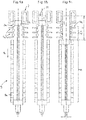
- Fig. 1d is the time in continuous casting shown, in which the supply of molten steel was just stopped in the mold.
- the drawing speed v corresponds to the second drawing speed v 2 of 0.36 m / min. This pull-out speed of the strand 1 is maintained until the end of the pull-out operation (see Fig. 3a ).
- the Fig. 7b shows an alternative to Fig. 7a , wherein the degree of coverage of the insulating flaps 9a of the strand at the strand end 1c is higher than at the strand beginning. This also increases the heat transfer coefficient U of the heat insulation 9 in the casting direction G.
- FIG. 10 schematically a head insulation 18 of a strand 1 is shown.
- the head insulation has a heat insulation 9 for the strand end 1c of the strand 1, so that the strand end 1c remains liquid longer.
- an exothermic powder 19 on the liquid strand end 1c be abandoned, which additionally heats the strand 1.
Landscapes
- Engineering & Computer Science (AREA)
- Mechanical Engineering (AREA)
- Continuous Casting (AREA)
Abstract
Die Erfindung betrifft ein Verfahren und eine Anlage zum Stranggießen eines metallischen Strangs (1) in einer Stranggießmaschine. Die Aufgabe der Erfindung besteht darin, bekannte Stranggießverfahren so zu verändern, dass die Ausbildung von Hohlräumen bzw. Rissen im Strang (1) verhindert wird. Diese Aufgabe wird durch das Verfahren nach Anspruch 1 gelöst, wobei die Intensität der Sekundärkühlung (4) über der Zeit t oder der Stranglänge s abnimmt, sodass ein Stranganfang (1a) intensiver abgekühlt wird als ein Strangende (1c).

Description
Die vorliegende Erfindung betrifft das Stranggießen, vorzugsweise das semi-kontinuierliche Stranggießen, eines metallischen Strangs in einer Stranggießmaschine.The present invention relates to continuous casting, preferably semi-continuous, continuous casting of a metallic strand in a continuous casting machine.
Konkret betrifft die Erfindung ein Verfahren zum Stranggießen, vorzugsweise zum semi-kontinuierlichen Stranggießen, eines Strangs in einer Stranggießmaschine, wobei die Stranggießmaschine eine Kokille mit einer Primärkühlung, in Gießrichtung nachfolgend eine Strangführung mit mehreren, vorzugsweise an den Strang anstellbaren, Strangführungsrollen zum Führen und einer Sekundärkühlung zum Abkühlen des Strangs, und wiederum nachfolgend eine Tertiärkühlzone zum gesteuerten oder geregelten Abkühlen des Strangs aufweist, umfassend die Verfahrensschritte:
- Einführen eines Kaltstrangs in die Kokille;
- Halten des Kaltstrangs in der Kokille, sodass ein Kopf des Kaltstrangs die Kokille fluiddicht verschließt;
- Angießen der Stranggießmaschine, wobei Metallschmelze in die Kokille gegossen wird und sich in der Kokille ein Gießspiegel und ein teilerstarrter Strang ausbildet;
- Beginnen des Ausziehens des Kaltstrangs aus der Kokille, wobei der Kaltstrang aus der Kokille ausgezogen wird;
- Stützen und Führen des teilerstarrten Strangs in der Strangführung, wobei der teilerstarrte Strang durch die Strangführungsrollen gestützt, geführt und durch Kühldüsen der Sekundärkühlung abgekühlt wird; und
- gesteuertes oder geregeltes Abkühlen des teilerstarrten Strangs bis zur Durcherstarrung des Strangs in der Tertiärkühlzone.
- Introducing a cold strand into the mold;
- Holding the dummy bar in the mold, so that a head of the dummy bar closes the mold fluid-tight;
- Casting the continuous casting machine, wherein molten metal is poured into the mold and forms in the mold a casting mirror and a partially solidified strand;
- Beginning to pull the cold strand out of the mold, pulling the cold strand out of the mold;
- Supporting and guiding the semi-solid strand in the strand guide, wherein the semi-solid strand is supported by the strand guide rollers, guided and cooled by cooling nozzles of the secondary cooling; and
- Controlled or controlled cooling of the partially solidified strand until the solidification of the strand in the tertiary cooling zone.
Außerdem betrifft die Erfindung eine Stranggießmaschine zum Stranggießen, vorzugsweise zum semi-kontinuierlichen Stranggießen, eines metallischen Strangs, die
- eine Kokille mit einer Primärkühlung,
- in Gießrichtung nachfolgend eine Strangführung mit mehreren, vorzugsweise an den Strang anstellbaren, Strangführungsrollen zum Führen und Stützen des Strangs, sowie eine Sekundärkühlung zum Abkühlen des Strangs, und
- wiederum nachfolgend eine Tertiärkühlzone zum gesteuerten oder geregelten Abkühlen des Strangs aufweist.
- a mold with a primary cooling,
- in the casting direction below a strand guide with several, preferably engageable with the strand, strand guide rollers for guiding and supporting the strand, and a secondary cooling to cool the strand, and
- in turn subsequently has a Tertiärkühlzone for controlled or controlled cooling of the strand.
Das gattungsgemäße Verfahren sowie eine geeignete Anlage sind aus der
Die Aufgabe der Erfindung besteht darin, bekannte Stranggießverfahren so zu verändern, dass Hohlräume bzw. Risse im Strang noch konsequenter verhindert werden. Dadurch soll die Innenqualität des vergossenen Strangs weiter verbessert werden.The object of the invention is to modify known continuous casting processes so that cavities or cracks in the strand are prevented even more consistently. This should further improve the internal quality of the cast strand.
Die erfindungsgemäße Ausgabe wird durch den Gegenstand von Anspruch 1 gelöst. Vorteilhafte Ausführungsformen sind Gegenstand der abhängigen Ansprüche.The output according to the invention is solved by the subject matter of
Konkret erfolgt die Lösung durch ein gattungsgemäßes Verfahren, wobei die Intensität der Sekundärkühlung über der Zeit t oder der Stranglänge s abnimmt, sodass ein Stranganfang intensiver abgekühlt wird als ein Strangende.Specifically, the solution is carried out by a generic method, wherein the intensity of the secondary cooling over the time t or the strand length s decreases, so that a Stranganfang is cooled more intense than a strand end.
Durch diese Maßnahme wird ein Strang, typischerweise ein Stahlstrang oder ein Strang aus einer sog. Superlegierung (siehe https://de.wikipedia.org/wiki/Superlegierung, z.B. einer Nickelbasislegierung), mit einer ausgeprägten V-förmigen Ausbildung der Strangschalen erzeugt. Mit anderen Worten nimmt das Dickenwachstum der Strangschalen in Gießrichtung rasch zu, sodass die Strangschale am unteren Ende des Strangs wesentlich dicker ist als am oberen Ende. Dadurch kann flüssige Metallschmelze etwaige durch die Erstarrung bedingte Hohlräume unmittelbar auffüllen, wodurch die Innenqualität des Strangs verbessert wird.By this measure, a strand, typically a steel strand or a strand of a so-called superalloy (see https://de.wikipedia.org/wiki/Superlegierung, for example, a nickel-based alloy), produced with a pronounced V-shaped configuration of the strand shells. In other words, the thickness growth of the strand shells in the casting direction increases rapidly, so that the strand shell at the lower end of the strand is substantially thicker than at the upper end. As a result, liquid molten metal can directly fill any voids caused by the solidification, which improves the internal quality of the strand.
Es ist zweckmäßig, wenn zur Stellung der Intensität ein Druck p und/oder eine Durchflussrate Q eines durch eine Kühldüse auf den Strang ausgebrachten Kühlmittels beeinflusst wird.It is expedient if a pressure p and / or a flow rate Q of a coolant discharged through a cooling nozzle onto the strand are influenced in order to set the intensity.
Besonders vorteilhaft ist es, wenn ein thermisches Rechenmodell während des Stranggießens in Abhängigkeit
- einer chemischen Zusammensetzung der Metallschmelze,
- der Primärkühlung des Strangs in der Kokille,
- einer Auszugsgeschwindigkeit des Strangs aus der Kokille, ständig das Ist-Temperaturfeld des Strangs einschließlich der Ist-Phasengrenzen zwischen den festen, teigigen und flüssigen Phasen im Strang berechnet, wobei die Intensität der Sekundärkühlung, wie ein Druck p und/oder eine Durchflussrate Q eines durch eine Kühldüse auf den Strang ausgebrachten Kühlmittels, in Abhängigkeit des Ist-Temperaturfelds und/oder der Ist-Phasengrenzen, insbesondere der Ist-Position der Sumpfspitze, eingestellt wird.
- a chemical composition of the molten metal,
- the primary cooling of the strand in the mold,
- an extraction rate of the strand from the mold, constantly the actual temperature field of the strand including the actual phase boundaries between the solid, doughy and liquid phases in the strand calculated, the intensity of the secondary cooling, such as a pressure p and / or a flow rate Q of a through a cooling nozzle on the strand discharged coolant, depending on the actual temperature field and / or the actual phase boundaries, in particular the actual position of the sump tip is set.
Die Berechnung des Ist-Temperaturfelds und die Steuerung der Sekundärkühlung ist z.B. aus der
Zusätzlich zur Veränderung der Intensität der Sekundärkühlung während des Gießprozesses ist es vorteilhaft, einen Wärmedurchgangskoeffizient U einer Wärmeisolation in der Tertiärkühlzone in Abhängigkeit des Ist-Temperaturfelds und/oder der Ist-Phasengrenzen, insbesondere der Ist-Position der Sumpfspitze, einzustellen.In addition to changing the intensity of the secondary cooling during the casting process, it is advantageous to set a heat transfer coefficient U of a heat insulation in the tertiary cooling zone as a function of the actual temperature field and / or the actual phase boundaries, in particular the actual position of the sump tip.
Weiters ist es günstig, dass nach dem Beginnen des Ausziehens der Kaltstrang mit einer ersten Ausziehgeschwindigkeit v1 aus der Kokille ausgezogen wird und anschließend die Ausziehgeschwindigkeit v des Kaltstrangs auf eine zweite Ausziehgeschwindigkeit v2 erhöht wird, wobei gilt v2 > v1.Furthermore, it is favorable that after commencing the drawing, the cold strand is drawn out of the mold at a first drawing speed v 1 and then the drawing speed v of the cold strand is increased to a second drawing speed v 2 , where v 2 > v 1 .
Das Erhöhen der Ausziehgeschwindigkeit v erfolgt in Abhängigkeit der Zeit t oder der Stranglänge s. Vorzugsweise erfolgt die Erhöhung stückweise stetig, bevorzugt zumindest einmal stetig differenzierbar.Increasing the pull-out speed v takes place as a function of the time t or the strand length s. Preferably, the increase is piecewise continuous, preferably at least once continuously differentiable.
Die letztgenannten Maßnahmen wirken sich ebenfalls sehr positiv auf die V-förmige Ausbildung der Strangschale aus.The latter measures also have a very positive effect on the V-shaped design of the strand shell.
Im Allgemeinen ist es vorteilhaft, wenn der Strang in der Tertiärkühlzone durch eine Wärmeisolation thermisch isoliert wird, wobei ein Wärmedurchgangskoeffizient U der Wärmeisolation in Gießrichtung zunimmt. Dadurch wird das untere Ende des Strangs, d.h. der Strangkopf, stärker abgekühlt als das obere Ende des Strangs, d.h. der Strangfußes.In general, it is advantageous if the strand is thermally insulated in the tertiary cooling zone by a thermal insulation, wherein a heat transfer coefficient U of the heat insulation increases in the casting direction. This will cause the lower end of the strand, i. the strand head, more cooled than the top of the strand, i. the string foot.
Eine weitere Verbesserung der Innenqualität des Strangs kann erreicht werden, wenn die Stranggießmaschine einen in Gießrichtung verfahrbaren Strangrührer umfasst, wobei der Strangrührer während des Ausziehens und nach dem Beenden des Ausziehens des Kaltstrangs aus der Kokille den Bereich der Sumpfspitze des Strangs elektromagnetisch rührt.A further improvement in the internal quality of the strand can be achieved if the continuous casting machine comprises a strand-movable in the casting direction, the Strand agitator during the extraction and after completing the withdrawal of the cold strand from the mold, the area of the bottom of the strand strand is electromagnetically stirred.
Die erfindungsgemäß Aufgabe wird ebenfalls durch eine Stranggießanlage nach Anspruch 10 gelöst. Vorteilhafte Ausführungsformen sind Gegenstand der abhängigen Ansprüche.The object of the invention is also achieved by a continuous casting plant according to
Konkret erfolgt die Lösung durch eine gattungsgemäße Stranggießmaschine, die eine Steuer- oder Regeleinrichtung zur zeit- oder stranglängenabhängigen Steuerung oder Regelung der Intensität der Sekundärkühlung aufweist.Specifically, the solution is carried out by a generic continuous casting machine having a control or regulating device for time or strand length-dependent control or regulation of the intensity of the secondary cooling.
Hierbei ist es vorteilhaft, wenn die Steuer- oder Regeleinrichtung ein thermisches Rechenmodell umfasst, das geeignet ist während des Stranggießens in Abhängigkeit
- einer chem. Zusammensetzung der Metallschmelze,
- einer Auszugsgeschwindigkeit des Strangs aus der Kokille,
- der Primärkühlung des Strangs in der Kokille, ständig das Ist-Temperaturfeld des Strangs einschließlich der Ist-Phasengrenzen zwischen den festen, teigigen und flüssigen Phasen im Strang zu berechnen, wobei die Intensität der Sekundärkühlung in Abhängigkeit des Ist-Temperaturfelds und/oder der Ist-Phasengrenzen, insbesondere der Ist-Position der Sumpfspitze, eingestellt werden kann.
- a chem. Composition of molten metal,
- an extraction speed of the strand from the mold,
- the primary cooling of the strand in the mold to constantly calculate the actual temperature field of the strand including the actual phase boundaries between the solid, doughy and liquid phases in the strand, the intensity of the secondary cooling being dependent on the actual temperature field and / or the actual temperature. Phase boundaries, in particular the actual position of the sump tip, can be adjusted.
Besonders vorteilhaft ist es, wenn eine Auszugsgeschwindigkeit v des Strangs aus der Kokille und/oder ein Wärmedurchgangskoeffizient U einer Wärmeisolation in der Tertiärkühlzone in Abhängigkeit des Ist-Temperaturfelds und/oder der Ist-Phasengrenzen, insbesondere der Ist-Position der Sumpfspitze, eingestellt werden kann.It is particularly advantageous if an extraction speed v of the strand from the mold and / or a heat transfer coefficient U of a heat insulation in the tertiary cooling zone can be set as a function of the actual temperature field and / or the actual phase boundaries, in particular the actual position of the sump tip ,
Weitere Vorteile und Merkmale der vorliegenden Erfindung ergeben sich aus der Beschreibung nicht einschränkender Ausführungsbeispiele. Die nachfolgenden schematisch dargestellten Figuren zeigen:
-
Fig 1a bis 1h die Verfahrensschritte bei der Durchführung des Verfahrens, -
Fig 2a ein stranggegossener Strang nach dem Stand der Technik, -
Fig 2b ein stranggegossener Strang, der gemäß der Erfindung hergestellt wurde, -
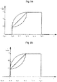
Fig 3a ein Verlauf einer Ausziehgeschwindigkeit eines Strangs aus einer Kokille über der Zeit t, -
Fig 3b ein Verlauf einer Ausziehgeschwindigkeit eines Strangs aus einer Kokille über der Stranglänge s, -
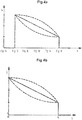
Fig 4a ein Verlauf einer Durchflussrate Q eines Kühlmittels durch eine Kühldüse über der Zeit t, -
Fig 4b ein Verlauf einer Durchflussrate Q eines Kühlmittels durch eine Kühldüse über der Stranglänge s, -
Fig 5 ein Darstellung einer auf einen Strang akkumulierten Kühlmittelmenge, -
Fig 6 eine Darstellung einer variablen Isolierung in der Tertiärkühlzone, -
Fig 7a eine Darstellung einer variablen Wärmeisolation in der Tertiärkühlzone durch verschwenkbare Isolierklappen, -
Fig 7b eine Darstellung einer variablen Wärmeisolation in der Tertiärkühlzone durch verschiebbare Isolierklappen, -
Fig 8a eine Darstellung einer nicht erfindungsgemäßen Stranggießmaschine mit einer Steuer- und Regeleinrichtung zur Einstellung der Auszugsgeschwindigkeit v, -
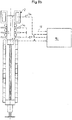
Fig 8b eine Darstellung einer erfindungsgemäßen Stranggießmaschine mit einer Steuer- und Regeleinrichtung zur Einstellung der Intensität der Sekundärkühlung, -
Fig 8c eine Darstellung einer nicht erfindungsgemäßen Stranggießmaschine mit einer Steuer- und Regeleinrichtung zur Einstellung der Wärmeisolierung in der Tertiärkühlzone, -
Fig 9a bis 9e eine Darstellung von Verfahrensschritten auf einer alternativen Stranggießmaschine zu denFig 1a ...1h , -
Fig 10 eine Darstellung einer Kopfisolierung, und -
Fig 11 eine Darstellung der Position der Sumpfspitze im Strang über der Zeit gemäß dem Stand der Technik und der Erfindung.
-
Fig 1a to 1h the process steps in carrying out the process, -
Fig. 2a a continuous casting strand according to the prior art, -
Fig. 2b a continuously cast strand made according to the invention, -
Fig. 3a a course of a withdrawal speed of a strand from a mold over the time t, -
Fig. 3b a course of a withdrawal speed of a strand from a mold over the strand length s, -
Fig. 4a a profile of a flow rate Q of a coolant through a cooling nozzle over the time t, -
4b a profile of a flow rate Q of a coolant through a cooling nozzle over the strand length s, -
Fig. 5 an illustration of a quantity of coolant accumulated on a line, -
Fig. 6 a representation of a variable insulation in the tertiary cooling zone, -
Fig. 7a a representation of a variable heat insulation in the tertiary cooling zone by means of pivotable insulating flaps, -
Fig. 7b a representation of a variable heat insulation in the tertiary cooling zone by sliding insulating flaps, -
Fig. 8a a representation of a non-inventive continuous casting machine with a control and regulating device for adjusting the pull-out speed v, -
Fig. 8b a representation of a continuous casting machine according to the invention with a control and regulating device for adjusting the intensity of the secondary cooling, -
Fig. 8c a representation of a non-inventive continuous casting machine with a control and regulating device for adjusting the thermal insulation in the tertiary cooling zone, -
9a to 9e a representation of process steps on an alternative continuous casting machine to theFig. 1a ...1h . -
FIG. 10 a representation of a head insulation, and -
Fig. 11 a representation of the position of the sump tip in the strand over time according to the prior art and the invention.
In den
In
In
In
In
Nachdem die Zufuhr von Stahlschmelze gestoppt wurde, sinkt der Gießspiegel G in der Kokille 2 ab (siehe
Die
In den
Die
Im Gegensatz dazu zeigt
Wie oben angeführt, zeigt die
Die
In beiden Fällen wird durch die Erhöhung der Ausziehgeschwindigkeit v nicht nur die Innenqualität des Strangs 1 erhöht, sondern auch die Wirtschaftlichkeit des Stranggießverfahrens verbessert, da mehr Stränge innerhalb derselben Zeit vergossen werden können.In both cases, not only the internal quality of the
Die Innenqualität des Strangs wird erfindungsgemäß durch eine Einstellung der Intensität der Sekundärkühlung 4 in Abhängigkeit der Zeit oder der Stranglänge s (siehe
Für den Fall, dass die Einstellung der Intensität der Sekundärkühlung 4 zusätzlich zur Änderung der Ausziehgeschwindigkeit v erfolgt, ist die Beschreibung der
Für den Fall, dass die Einstellung der Intensität der Sekundärkühlung 4 anstelle der Änderung der Ausziehgeschwindigkeit v erfolgt, ist die Beschreibung der
In
In
In
Die
In
Die
Die
In den
In
In
Obwohl die Erfindung im Detail durch die bevorzugten Ausführungsbeispiele näher illustriert und beschrieben wurde, so ist die Erfindung nicht durch die offenbarten Beispiele eingeschränkt und andere Variationen können vom Fachmann hieraus abgeleitet werden, ohne den Schutzumfang der Erfindung zu verlassen.While the invention has been further illustrated and described in detail by the preferred embodiments, the invention is not limited by the disclosed examples, and other variations can be derived therefrom by those skilled in the art without departing from the scope of the invention.
- 11
- Strangstrand
- 1a1a
- Stranganfangtrain early
- 1b1b
- teilerstarrter Strangpartially solid strand
- 1c1c
- Strangendestrand end
- 22
- Kokillemold
- 2a2a
- Primärkühlungprimary cooling
- 33
- Strangführungstrand guide
- 3a3a
- StrangführungsrollenStrand guide rolls
- 44
- Sekundärkühlung, SekundärkühlzoneSecondary cooling, secondary cooling zone
- 4a4a
- Kühldüsecooling nozzle
- 55
- Tertiärkühlung, TertiärkühlzoneTertiary cooling, tertiary cooling zone
- 66
- Kaltstrangdummy bar
- 77
- Rechenmodellcomputer model
- 88th
- Sumpfspitzecrater tip
- 99
- Wärmeisolationthermal insulation
- 9a9a
- Isolationspanelinsulation panel
- 1010
- Steuer- oder RegeleinrichtungControl or regulating device
- 1111
- Strangschalestrand shell
- 1212
- flüssiger Bereich des Strangsliquid area of the strand
- 1313
- KopfheizungHeating head
- 1414
- StrangrührerStrangrührer
- 1515
- chemische Zusammensetzungchemical composition
- 1616
- Motorengine
- 1717
- Strahlungsbereichradiation range
- 1818
- Kopfisolierunghead insulation
- 1919
- exothermes Pulverexothermic powder
- GG
- Gießrichtungcasting
- LL
- Stranglängestrand length
- MM
- Gießspiegelmeniscus
- DurchflussrateFlow rate
- SS
- Stranglängestrand length
- tt
- ZeitTime
- UU
- WärmedurchgangskoeffizientHeat transfer coefficient
- vv
- Ausziehgeschwindigkeit, GießgeschwindigkeitExtraction speed, casting speed
Claims (12)
Priority Applications (1)
| Application Number | Priority Date | Filing Date | Title |
|---|---|---|---|
| EP17184956.5A EP3437757A1 (en) | 2017-08-04 | 2017-08-04 | Continuous casting of a metallic strand |
Applications Claiming Priority (1)
| Application Number | Priority Date | Filing Date | Title |
|---|---|---|---|
| EP17184956.5A EP3437757A1 (en) | 2017-08-04 | 2017-08-04 | Continuous casting of a metallic strand |
Publications (1)
| Publication Number | Publication Date |
|---|---|
| EP3437757A1 true EP3437757A1 (en) | 2019-02-06 |
Family
ID=59558285
Family Applications (1)
| Application Number | Title | Priority Date | Filing Date |
|---|---|---|---|
| EP17184956.5A Withdrawn EP3437757A1 (en) | 2017-08-04 | 2017-08-04 | Continuous casting of a metallic strand |
Country Status (1)
| Country | Link |
|---|---|
| EP (1) | EP3437757A1 (en) |
Citations (10)
| Publication number | Priority date | Publication date | Assignee | Title |
|---|---|---|---|---|
| AT303987B (en) * | 1968-12-31 | 1972-12-27 | Uss Eng & Consult | Device for the automatic control of the cooling rate of a cast strand leaving a mold |
| AT341127B (en) * | 1972-09-06 | 1978-01-25 | Concast Ag | METHOD FOR CONTROLLING THE COOLING OF A STRING EXITING FROM A CONTINUOUS CHOCOLATE AND DEVICE FOR CARRYING OUT THIS METHOD |
| DE3937752A1 (en) * | 1988-11-22 | 1991-05-16 | Hitachi Shipbuilding Eng Co | Automatically starting continuous casting appts. |
| DE4417808A1 (en) | 1993-05-24 | 1994-12-01 | Voest Alpine Ind Anlagen | Method for the continuous casting of a metal billet |
| US20040172153A1 (en) * | 2002-12-12 | 2004-09-02 | Yale Zhang | Method and online system for monitoring continuous caster start-up operation and predicting start cast breakouts |
| WO2009141205A1 (en) | 2008-05-21 | 2009-11-26 | Siemens Vai Metals Technologies Gmbh & Co. | Method for the continuous casting of a metal strand |
| JP2013022609A (en) * | 2011-07-20 | 2013-02-04 | Nippon Steel & Sumitomo Metal Corp | Continuous casting method for steel |
| WO2015079071A2 (en) | 2014-03-27 | 2015-06-04 | Primetals Technologies Austria GmbH | Semi-continuous casting of a steel strip |
| EP2788133B1 (en) * | 2011-12-05 | 2016-02-03 | Primetals Technologies Austria GmbH | Process engineering measures in a strand casting machine at the beginning of casting, at the end of casting, and during the manufacturing of a transition piece |
| EP3184202A1 (en) * | 2015-11-30 | 2017-06-28 | SMS group GmbH | Method for continuously casting a metal strand and casting strand obtained by this process |
-
2017
- 2017-08-04 EP EP17184956.5A patent/EP3437757A1/en not_active Withdrawn
Patent Citations (11)
| Publication number | Priority date | Publication date | Assignee | Title |
|---|---|---|---|---|
| AT303987B (en) * | 1968-12-31 | 1972-12-27 | Uss Eng & Consult | Device for the automatic control of the cooling rate of a cast strand leaving a mold |
| AT341127B (en) * | 1972-09-06 | 1978-01-25 | Concast Ag | METHOD FOR CONTROLLING THE COOLING OF A STRING EXITING FROM A CONTINUOUS CHOCOLATE AND DEVICE FOR CARRYING OUT THIS METHOD |
| DE3937752A1 (en) * | 1988-11-22 | 1991-05-16 | Hitachi Shipbuilding Eng Co | Automatically starting continuous casting appts. |
| DE4417808A1 (en) | 1993-05-24 | 1994-12-01 | Voest Alpine Ind Anlagen | Method for the continuous casting of a metal billet |
| US20040172153A1 (en) * | 2002-12-12 | 2004-09-02 | Yale Zhang | Method and online system for monitoring continuous caster start-up operation and predicting start cast breakouts |
| WO2009141205A1 (en) | 2008-05-21 | 2009-11-26 | Siemens Vai Metals Technologies Gmbh & Co. | Method for the continuous casting of a metal strand |
| JP2013022609A (en) * | 2011-07-20 | 2013-02-04 | Nippon Steel & Sumitomo Metal Corp | Continuous casting method for steel |
| EP2788133B1 (en) * | 2011-12-05 | 2016-02-03 | Primetals Technologies Austria GmbH | Process engineering measures in a strand casting machine at the beginning of casting, at the end of casting, and during the manufacturing of a transition piece |
| WO2015079071A2 (en) | 2014-03-27 | 2015-06-04 | Primetals Technologies Austria GmbH | Semi-continuous casting of a steel strip |
| EP3122492B1 (en) * | 2014-03-27 | 2017-07-05 | Primetals Technologies Austria GmbH | Semi-continuous casting of a steel ingot |
| EP3184202A1 (en) * | 2015-11-30 | 2017-06-28 | SMS group GmbH | Method for continuously casting a metal strand and casting strand obtained by this process |
Non-Patent Citations (1)
| Title |
|---|
| ZHANG Y ET AL: "Industrial application of multivariate SPC to continuous caster start-up operations for breakout prevention", CONTROL ENGINEERING PRACTICE, PERGAMON PRESS, OXFORD, GB, vol. 14, no. 11, 1 November 2006 (2006-11-01), pages 1357 - 1375, XP027906106, ISSN: 0967-0661, [retrieved on 20061101] * |
Similar Documents
| Publication | Publication Date | Title |
|---|---|---|
| EP3122492B2 (en) | Semi-continuous casting of a steel ingot | |
| EP3437759B1 (en) | Continuous casting of a metallic strand | |
| WO2001003867A1 (en) | Method and device for making a metal strand | |
| DE3538222C2 (en) | ||
| WO2008052689A1 (en) | Method and control device for controlling the heat removal from a side plate of a mould | |
| EP2025432B1 (en) | Method for creating steel long products through strand casting and rolling | |
| DE69801945T2 (en) | Casting metal strips | |
| EP3437756B1 (en) | Continuous casting of a metallic strand | |
| AT411822B (en) | METHOD AND DEVICE FOR STARTING A CASTING PROCESS | |
| EP3437757A1 (en) | Continuous casting of a metallic strand | |
| DE3221708C1 (en) | Process and apparatus for filling a continuous casting mould while casting a strand | |
| EP1077782A1 (en) | Method and device for casting metal close to final dimensions | |
| AT517006A1 (en) | Continuous casting with optimized oscillation of the continuous casting mold | |
| EP3733323A1 (en) | Method and continuous casting plant for casting a cast strand | |
| EP1550523A1 (en) | Diversified regulation of the secondary cooling of a continuous casting machine | |
| EP0959995B1 (en) | Method for vertical continuous casting of metals | |
| AT142197B (en) | Method and device for the direct shaping of liquid metals. | |
| DE69000282T2 (en) | METHOD AND DEVICE FOR THE PRODUCTION OF THICK METAL PRODUCTS BY MEANS OF CONTINUOUS CASTING. | |
| CH663917A5 (en) | METHOD AND ARRANGEMENT FOR CONTINUOUSLY THINNING SLABS. | |
| WO2009068232A1 (en) | Method and device for equalizing the solidification process of a fusible metal, particularly produced by means of strand or strip casting | |
| EP4423303A1 (en) | Method for producing a dual-phase steel strip in a combined casting and rolling system, a dual-phase steel strip produced by means of the method, and a combined casting and rolling system | |
| EP3015192B1 (en) | Method and device for the continuous casting of a light metal alloy | |
| CH718935B1 (en) | Process for continuous casting and software product for carrying out the process. | |
| KR20200064263A (en) | Continuous casting of a metallic strand | |
| EP3703883A1 (en) | Continuous casting line having individual roller engagement |
Legal Events
| Date | Code | Title | Description |
|---|---|---|---|
| PUAI | Public reference made under article 153(3) epc to a published international application that has entered the european phase |
Free format text: ORIGINAL CODE: 0009012 |
|
| STAA | Information on the status of an ep patent application or granted ep patent |
Free format text: STATUS: THE APPLICATION HAS BEEN PUBLISHED |
|
| AK | Designated contracting states |
Kind code of ref document: A1 Designated state(s): AL AT BE BG CH CY CZ DE DK EE ES FI FR GB GR HR HU IE IS IT LI LT LU LV MC MK MT NL NO PL PT RO RS SE SI SK SM TR |
|
| AX | Request for extension of the european patent |
Extension state: BA ME |
|
| STAA | Information on the status of an ep patent application or granted ep patent |
Free format text: STATUS: REQUEST FOR EXAMINATION WAS MADE |
|
| 17P | Request for examination filed |
Effective date: 20190806 |
|
| RBV | Designated contracting states (corrected) |
Designated state(s): AL AT BE BG CH CY CZ DE DK EE ES FI FR GB GR HR HU IE IS IT LI LT LU LV MC MK MT NL NO PL PT RO RS SE SI SK SM TR |
|
| STAA | Information on the status of an ep patent application or granted ep patent |
Free format text: STATUS: EXAMINATION IS IN PROGRESS |
|
| 17Q | First examination report despatched |
Effective date: 20200610 |
|
| STAA | Information on the status of an ep patent application or granted ep patent |
Free format text: STATUS: EXAMINATION IS IN PROGRESS |
|
| STAA | Information on the status of an ep patent application or granted ep patent |
Free format text: STATUS: EXAMINATION IS IN PROGRESS |
|
| GRAP | Despatch of communication of intention to grant a patent |
Free format text: ORIGINAL CODE: EPIDOSNIGR1 |
|
| STAA | Information on the status of an ep patent application or granted ep patent |
Free format text: STATUS: GRANT OF PATENT IS INTENDED |
|
| INTG | Intention to grant announced |
Effective date: 20220516 |
|
| STAA | Information on the status of an ep patent application or granted ep patent |
Free format text: STATUS: THE APPLICATION IS DEEMED TO BE WITHDRAWN |
|
| 18D | Application deemed to be withdrawn |
Effective date: 20220927 |